JP4570859B2 - Relay welding detection device and relay welding detection method - Google Patents
Relay welding detection device and relay welding detection methodInfo
- Publication number
- JP4570859B2 JP4570859B2 JP2003352828A JP2003352828A JP4570859B2 JP 4570859 B2 JP4570859 B2 JP 4570859B2 JP 2003352828 A JP2003352828 A JP 2003352828A JP 2003352828 A JP2003352828 A JP 2003352828A JP 4570859 B2 JP4570859 B2 JP 4570859B2
- Authority
- JP
- Japan
- Prior art keywords
- relay
- state
- predetermined
- welding
- value
- Prior art date
- Legal status (The legal status is an assumption and is not a legal conclusion. Google has not performed a legal analysis and makes no representation as to the accuracy of the status listed.)
- Expired - Fee Related
Links
Images
Classifications
-
- Y—GENERAL TAGGING OF NEW TECHNOLOGICAL DEVELOPMENTS; GENERAL TAGGING OF CROSS-SECTIONAL TECHNOLOGIES SPANNING OVER SEVERAL SECTIONS OF THE IPC; TECHNICAL SUBJECTS COVERED BY FORMER USPC CROSS-REFERENCE ART COLLECTIONS [XRACs] AND DIGESTS
- Y02—TECHNOLOGIES OR APPLICATIONS FOR MITIGATION OR ADAPTATION AGAINST CLIMATE CHANGE
- Y02T—CLIMATE CHANGE MITIGATION TECHNOLOGIES RELATED TO TRANSPORTATION
- Y02T10/00—Road transport of goods or passengers
- Y02T10/60—Other road transportation technologies with climate change mitigation effect
- Y02T10/62—Hybrid vehicles
-
- Y—GENERAL TAGGING OF NEW TECHNOLOGICAL DEVELOPMENTS; GENERAL TAGGING OF CROSS-SECTIONAL TECHNOLOGIES SPANNING OVER SEVERAL SECTIONS OF THE IPC; TECHNICAL SUBJECTS COVERED BY FORMER USPC CROSS-REFERENCE ART COLLECTIONS [XRACs] AND DIGESTS
- Y02—TECHNOLOGIES OR APPLICATIONS FOR MITIGATION OR ADAPTATION AGAINST CLIMATE CHANGE
- Y02T—CLIMATE CHANGE MITIGATION TECHNOLOGIES RELATED TO TRANSPORTATION
- Y02T10/00—Road transport of goods or passengers
- Y02T10/60—Other road transportation technologies with climate change mitigation effect
- Y02T10/7072—Electromobility specific charging systems or methods for batteries, ultracapacitors, supercapacitors or double-layer capacitors
Landscapes
- Electric Propulsion And Braking For Vehicles (AREA)
- Testing Electric Properties And Detecting Electric Faults (AREA)
- Hybrid Electric Vehicles (AREA)
- Keying Circuit Devices (AREA)
Description
本発明は、リレー溶着検出装置及びリレー溶着検出方法に関し、特に、バッテリと負荷回路とを接続するリレーの溶着を検出するためのリレー溶着検出装置及びリレー溶着検出方法に関する。 The present invention relates to a relay welding detection device and a relay welding detection method, and more particularly to a relay welding detection device and a relay welding detection method for detecting welding of a relay connecting a battery and a load circuit.
従来より、高電圧のバッテリ等からモータ等への電力供給を制御するためにリレーが一般に使用されている。例えば、電気自動車、ハイブリッド自動車等において、高電圧のバッテリから高電圧系回路部品への電力供給を制御するために、バッテリと高電圧系回路部品との間にリレーを設け、高電圧系回路部品とバッテリとの接続及び開放は、車両制御状態に応じてリレーにより行われる。 Conventionally, a relay is generally used to control power supply from a high voltage battery or the like to a motor or the like. For example, in an electric vehicle, a hybrid vehicle, etc., in order to control power supply from a high voltage battery to a high voltage system circuit component, a relay is provided between the battery and the high voltage system circuit component, and the high voltage system circuit component The connection and release of the battery and the battery are performed by a relay according to the vehicle control state.
このような場合、リレーは過電流等の原因により溶着することがあるので、そのリレーの溶着を検出するために、各リレーに直列に接続されたフォトカプラと、リレーの開放時にフォトダイオードが点灯しているか否かを検出するための回路とを有する溶着検出回路をリレーに付加することによって、リレーの溶着検出を行っている。 In such a case, the relay may be welded due to an overcurrent or the like. Therefore, in order to detect the welding of the relay, the photocoupler connected in series with each relay and the photodiode lights up when the relay is opened. The welding detection of the relay is performed by adding a welding detection circuit having a circuit for detecting whether or not the relay is operating to the relay.
しかし、リレーの溶着検出専用の溶着検出回路を付加することは、コスト、設置スペース等の問題があるため、このような問題を解決するために、特別な回路等の機器を付加せずに、リレーの故障を診断する方法が提案されている(例えば、特許文献1参照)。
その提案によれば、特別な回路等の機器を付加せずに、リレーが故障しているか否かは診断できるものの、その提案では、バッテリの+(プラス)側リレーと−(マイナス)側リレーのどちらが溶着故障しているかということを特定することができなかった。+(プラス)側リレーと−(マイナス)側リレーのどちらが溶着しているかが判明できれば、修理等の対応を迅速に行うことができる。 According to the proposal, although it is possible to diagnose whether or not the relay has failed without adding a device such as a special circuit, in the proposal, the + (plus) side relay and the-(minus) side relay of the battery are proposed. It was not possible to identify which of the two had a welding failure. If it becomes clear which of the + (plus) side relay and the-(minus) side relay is welded, it is possible to quickly perform repairs and the like.
そこで、本発明は、溶着検出回路等の専用の回路を付加することなく、バッテリの+側、−側のどちらのリレーが故障しているかを診断できる溶着検出装置を提供することを目的とする。 SUMMARY OF THE INVENTION Accordingly, an object of the present invention is to provide a welding detection device capable of diagnosing whether the relay on the + side or the − side of the battery has failed without adding a dedicated circuit such as a welding detection circuit. .
本発明のリレー溶着検出装置は、負荷回路とバッテリの間に接続され、該バッテリの+側に接続される+側リレーと、前記バッテリの−側に接続される−側リレーの溶着を検出する装置であって、前記+側リレーと前記−側リレーが共にオン、かつ前記+側リレーに並列に設けられる、プリチャージリレーとプリチャージ用抵抗器からなる直列回路の前記プリチャージリレーがオフの状態から、前記+側リレーと前記プリチャージリレーがオフ、かつ前記−側リレーがオンの状態である第1の状態に変更する第1の状態変更手段と、前記第1の状態における前記負荷回路側の電圧値が、予め決められた第1の時間経過後において予め決められた第1の値以上変化しない場合に、前記+側リレーを溶着と判定する第1の溶着判定手段と、前記第1の状態から、前記+側リレーと前記−側リレーがオフ、かつ前記プリチャージリレーがオンの状態である第2の状態に変更する第2の状態変更手段と、前記第2の状態における前記負荷回路側の電圧値が、予め決められた第2の時間経過後において予め決められた第2の値以上変化しない場合に、前記−側リレーを溶着と判定する第2の溶着判定手段とを有する。 Relay welding detecting device of the present invention is connected between the load circuit and the battery, and the + side relays being connected to the positive side of the battery, the battery - are connected to the side - detecting the welding of the side relay The positive-side relay and the negative-side relay are both on, and the pre-charge relay of a series circuit including a pre-charge relay and a pre-charging resistor provided in parallel to the positive-side relay is off. The first state changing means for changing from the state to the first state in which the + side relay and the precharge relay are off and the-side relay is on, and the load in the first state A first welding determination means for determining that the + side relay is welded when a voltage value on the circuit side does not change more than a predetermined first value after elapse of a predetermined first time; and First Second state changing means for changing from the state to the second state in which the + side relay and the-side relay are off and the precharge relay is on, and the load in the second state A second welding determination means for determining that the negative relay is welded when the voltage value on the circuit side does not change by a predetermined second value after a predetermined second time has elapsed; .
本発明によれば、溶着検出回路等の専用の回路を付加することなく、バッテリの+側、−側のどちらのリレーが故障しているかを診断できる溶着検出装置を実現することができる。 ADVANTAGE OF THE INVENTION According to this invention, the welding detection apparatus which can diagnose whether the relay of + side or-side of a battery has failed can be implement | achieved, without adding dedicated circuits, such as a welding detection circuit.
以下、図面を参照して本発明の実施の形態に係るリレー溶着検出装置を説明する。
(第1の実施の形態)
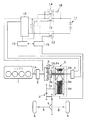
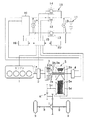
図1は、第1の実施の形態に係わる車両の駆動系の構成を示す構成図である。
本実施の形態に係る車両は、エンジンとモータとを併用するパラレルハイブリッド式の車両であり、図1に示すように、エンジン1と、エンジン1の起動及び発電・動力アシストを担う第1のモータ2(以下、単にモータ2という)と、エンジン1の出力軸1aにモータ2を介して連結されるプラネタリギヤユニット3と、このプラネタリギヤユニット3の機能を制御し、発進・後進時の駆動力源になるとともに減速エネルギの回収を担う第2のモータ4(以下、単にモータ4という)と、変速及びトルク増幅を行なって走行時の動力変換機能を担う動力変換機構5とを基本構成とする駆動系を備えている。
Hereinafter, a relay welding detection apparatus according to an embodiment of the present invention will be described with reference to the drawings.
(First embodiment)
FIG. 1 is a configuration diagram showing the configuration of a vehicle drive system according to the first embodiment.
The vehicle according to the present embodiment is a parallel hybrid vehicle that uses both an engine and a motor. As shown in FIG. 1, the
プラネタリギヤユニット3は、サンギヤ3a、このサンギヤ3aに噛合するピニオンを回転自在に支持するキャリア3b、ピニオンと噛合するリングギヤ3cを有するシングルピニオン式のプラネタリギヤである。また、動力変換機構5としては、歯車列を組み合わせた変速機や流体トルクコンバータを用いた変速機等を用いることが可能であるが、入力軸5aに軸支されるプライマリプーリ5bと出力軸5cに軸支されるセカンダリプーリ5dとの間に駆動ベルト5eを巻装してなるベルト式無段変速機(CVT)を採用することが望ましく、本実施の形態においては、以下、動力変換機構5をCVT5として説明する。
The
すなわち、本実施の形態におけるハイブリッド自動車の駆動系では、エンジン1の出力軸1aとCVT5の入力軸5aとの間にプラネタリギヤユニット3が配置されている。このプラネタリギヤユニット3のリングギヤ3cがエンジン1の出力軸1aに一方のモータ2を介して結合されるとともに、キャリア3bがCVT5の入力軸5aに結合され、サンギヤ3aに他方のモータ4が連結されている。そして、CVT5の出力軸5cに減速歯車列6を介してデファレンシャル機構7が連設され、このデファレンシャル機構7に駆動軸8を介して前輪或いは後輪の駆動輪9が連設される。
That is, in the hybrid vehicle drive system in the present embodiment,
モータ2、4は、インバータ10に接続され、インバータ10にバッテリ11が接続されている。バッテリ11の負荷回路であるインバータ10は、モータ2、4からの交流電力の供給を受け、バッテリ11の充電を行ったり、バッテリ11からの直流電力の供給を受け、モータ2,4を駆動させる。
The
バッテリ11のプラス側(以下、+側と略す)は、メインリレーの+側リレー12を介して、インバータ10に接続されている。バッテリ11のマイナス側(以下、−側と略す)は、メインリレーの−側リレー13を介して、インバータ10に接続されている。さらに、+側リレー12に並列にプリチャージリレー14が接続されている。
Positive side of the battery 11 (hereinafter, referred to as + side) through the +
+側リレー12、−側リレー13及びプリチャージリレー14のオン・オフの制御は、車両制御ユニット15によって行われる。インバータ10の制御は、インバータ制御ユニット16によって行われる。インバータ制御ユニット16へは、インバータ10の端子電圧を測定する電圧計17の出力信号が入力され、さらに、インバータ制御ユニット16は、車両制御ユニット15とデータ通信を行う。従って、インバータ制御ユニット16は、電圧計17の出力と車両の制御状態に応じて、直流と交流間の変換の制御、モータの回転数の制御等を行う。なお、電圧計17は、直接電圧を測定する通常の電圧計でもよいし、電圧を光量等に変換して間接的に電圧を測定する装置でもよい。
The
車両制御ユニット15は、中央処理装置(以下、CPUという)と、読み出し専用メモリ(ROM)と、ランダムアクセスメモリ(RAM)と、種々のインターフェースを有する。ROMに記憶された予め決められたプログラムが、CPUによって実行されることによって、後述する溶着検出を含む種々の機能を、車両制御ユニット15は実現することができる。
The
なお、プリチャージリレー14は、バッテリ11とインバータ10の接続時に+側リレー12に急激に高電圧が印加されるのを防ぐために、+側リレー12をオンする前にオンされるリレーである。プリチャージリレー14と直列にプリチャージ用の抵抗器18が接続される。そのプリチャージリレー14と抵抗器18からなる直列回路が、+側リレー12に並列に設けられる。よって、+側リレー12をオンするときは、まずプリチャージリレー14をオンし、その後、+側リレー12がオンするので、+側リレー12に急激に高電圧が印加されることを防ぐことができる。
The
また、エンジン1、2つのモータ2,4、CVT5は、車両制御ユニット15によって集中制御される。この車両制御ユニット15は、エンジン1、2つのモータ2,4、CVT5の作動状態やバッテリ11の状態を監視し、ドライバによるイグニッションキーの操作、アクセルペダルやブレーキペダルの踏み込み操作、ステアリングの操舵等の情報に基づいて、エンジン1の制御、インバータ10を介してのモータ2,4の駆動及びバッテリ11の充電制御、CVT5の変速比や供給油圧の制御等を行う。
The
以上の構成による駆動系では、前述したように、エンジン1及びモータ2をプラネタリギヤユニット3のリングギヤ3cへ結合するとともにサンギヤ3aにモータ4を結合してキャリア3bから出力を得るようにし、さらに、キャリア3bからの出力をCVT5によって変速及びトルク増幅して駆動輪9に伝達するようにしているため、2つのモータ2,4は発電と駆動力供給との両方に使用することができ、比較的小出力のモータを使用することができる
次に、本実施の形態に関わるリレー溶着検出方法について、説明する。
In the drive system configured as described above, as described above, the
リレーの溶着検出は、車両の停止時、言い換えれば、イグニッションキーをオフにしたときに、車両制御ユニット15によって行われる。より具体的には、リレーの溶着検出は、バッテリ11と高電圧系回路であるインバータ10との接続を切るとき(バッテリ11とインバータ10が接続されている状態から切断するとき)に行われる。そして、インバータ10の端子電圧が落ちきってしまう前に、リレーを所定の制御シーケンスでオン及びオフの制御を行いながら、リレーの溶着検出を行う。リレーの溶着検出は、車両制御ユニット15のCPUが、ROMに記憶されたリレー溶着検出プログラムを実行することによって行われる。
ちなみに、車両のエンジン始動時、言い換えれば、イグニッションキーをオンにしたときは、−側リレー13、プリチャージリレー14、そして+側リレー12の順でオンし、その後プリチャージリレー14がオフする。これによって、バッテリ11からの電力供給が開始される。
The detection of relay welding is performed by the
Incidentally, when the vehicle engine is started, in other words, when the ignition key is turned on, the -
図2及び図3を用いて、溶着検出のための処理について説明する。
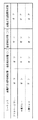
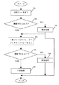
図2は、溶着検出時の、+側リレー12、−側リレー13及びプリチャージリレー14のリレー制御シーケンスを説明するための図である。図3は、溶着検出処理の流れの例を示すフローチャートである。
車両が運転状態であるとき、高電圧系回路であるインバータ10とバッテリ11は接続状態にあるので、図2の高電圧系回路接続状態に示すように、各リレーは、+側リレー12と−側リレー13はオンで、プリチャージリレー14はオフの状態である。
The process for detection of welding will be described with reference to FIGS.
FIG. 2 is a diagram for explaining a relay control sequence of the +
When the vehicle is in an operating state, the
ドライバーがイグニッションキーを回して車両制御を停止したとき(以下、車両制御停止時という)に、図3の処理が実行される。
車両制御停止時、まず、車両制御ユニット15から+側リレー12にオフの制御信号を出力することによって、メインリレーの+側リレー12をオフする(ステップ(以下、Sと略す)1)ことによって、リレーの接続状態を変更する。このとき、図2の溶着判定状態(1)に示すように、各リレーは、+側リレー12はオフで、−側リレー13はオンのままであり、プリチャージリレー14はオフの状態(以下、第1の状態ともいう)のままである。
When the driver turns the ignition key to stop vehicle control (hereinafter referred to as vehicle control stop), the processing of FIG. 3 is executed.
When the vehicle control is stopped, the
次に、第1の状態において、電圧計17が出力する電圧値が、予め設定された閾値TH1a以下になったか否かを判定する(S2)。+側リレー12が溶着していると、電圧制御ユニット15からの制御信号によって、+側リレー12はオフしようとしても、電圧計17が出力する電圧値は、時間の経過と共に低下しない。従って、電圧計17が出力する電圧値が、予め決められた時間経過後において、電圧低下による予め決められた値以上の変化がなければ、+側リレー12は溶着していると判定され、S2でNOとなり、異常処理を行い(S3)、処理は終了する。なお、S3の処理の後は、図3において点線の矢印で示すように、S4の処理へ移行してもよい。
+側リレー12が溶着していなければ、電圧制御ユニット15からの制御信号によって、+側リレー12はオフすなわち開放するので、電圧計17が出力する電圧値は、時間の経過と共に低下する。従って、電圧計17が出力する電圧値が、予め決められた時間経過後において、電圧低下により予め決められた値以上の変化があれば、+側リレー12は溶着していないと判定され、S2でYESとなり、S4の処理へ移行する。
Next, in the first state, it is determined whether or not the voltage value output from the
If + have
次に、S4において、−側リレー13をオフし、プリチャージリレー14をオンにする(S4)ことによって、リレーの接続状態を変更する。このとき、図2の溶着判定状態(2)に示すように、各リレーは、+側リレー12はオフのままで、−側リレー13はオフで、プリチャージリレー14はオンの状態(以下、第2の状態ともいう)のままである。
Next, in S4, the
次に、第2の状態において、電圧計13が出力する電圧値が、予め決められた時間内に予め設定された閾値TH1b以下になったか否かを判定する(S5)。−側リレー13が溶着していると、電圧制御ユニット15からの制御信号によって、−側リレー13はオフしようとしても、電圧計17が出力する電圧値は、時間の経過と共に低下しない。従って、電圧計17が出力する電圧値が、予め決められた時間経過後において、電圧低下により予め決められた値(この値は、上述したS3における予め決められた値と同じでもよいし、異なってもよい)以上の変化がなければ、−側リレー13は溶着していると判定され、S5でNOとなり、異常処理を行い(S6)、処理は終了する。
Next, in the second state, it is determined whether or not the voltage value output from the
なお、S3及びS6の異常処理においては、溶着状態を車両に搭載された警告表示部に警告表示を行う、異常の内容(溶着故障)を示す故障コードを車両制御ユニット15内の不揮発性メモリの所定の記憶領域に記録する等の処理が行われる。車両のメンテナンスマンが、車両のチェック、メンテナンス等を行うとき、どのリレーが溶着しているかを、警告表示部における表示、あるいは不揮発性メモリのデータに基づく故障診断装置等における表示によって、知ることができれば、感電等の事故の未然防止に繋がる。さらに、異常処理において、次にイグニッションキーがオンになっても、メインリレーへのオン信号が出力されないように、リレーの制御が制限されるようにしてもよい。
In the abnormality process of S3 and S6, a failure code indicating the content of the abnormality (welding failure) is displayed in the warning display unit mounted on the vehicle in the welding state, and the failure code indicating the failure state is stored in the nonvolatile memory in the
−側リレー13が溶着していなければ、電圧制御ユニット15からの制御信号によって、−側リレー13はオフすなわち開放するので、電圧計17が出力する電圧値は、時間の経過と共に低下する。従って、予め決められた時間経過後において、電圧計17が出力する電圧値に、電圧低下による予め決められた値以上の変化があれば、−側リレー13は溶着していないと判定され、S5でYESとなり、S7の処理へ移行する。
If the -
S7では、+側リレー12と−側リレー13が共に、溶着していないので、正常処理を行う。この正常処理は、何も実行しなくてもよいが、正常であった旨のデータ、例えば時刻データと共に正常であることを示すコードを、車両制御ユニット15の不揮発性メモリ等に記録するようにしてもよい。
In S7, since both the +
そして、処理は終了し、その結果、全リレー、すなわち+側リレー12、−側リレー13及びプリチャージリレー14を接続状態にする制御信号は出力されないので、溶着しているリレーを除き、全リレーは開放状態になる。
従って、メインリレーの+側リレー12と−側リレー13のいずれが溶着故障しているかを検出することができる。特に、+側リレーは溶着し易いため、+側リレーが−側リレーよりも先にチェックされる。
Then, the process ends, and as a result, all relays, that is, control signals for connecting the +
Thus, the main relay +
なお、上述した閾値TH1aとTH1bは、溶着判定時間を短くするように調整して設定される。
さらになお、インバータによっては、電圧低下に応じて、強制的に放電する機能を有するものがあるが、そのような機能を有するインバータの場合は、溶着判定中は、放電を停止させるように制御してもよい。
The threshold values TH1a and TH1b described above are adjusted and set so as to shorten the welding determination time.
Furthermore, some inverters have a function of forcibly discharging in response to a voltage drop. In the case of an inverter having such a function, control is performed so that the discharge is stopped during welding determination. May be.
以上のように、本実施の形態に係るハイブリッド車両には、メインのバッテリを高電圧系回路に接続するためのリレーである、+側リレー12、−側リレー13、プリチャージリレー14と、これらのリレーを制御する制御手段である車両制御ユニット15と、インバータ10の端子電圧(高電圧系回路側の電圧)を検出する手段である電圧計17とが含まれる。車両制御ユニット15には、リレー溶着を検出する手段であるプログラムが含まれる。そして、車両制御ユニット15は、各リレーを所定のシーケンスで制御することによって、バッテリを高電圧系回路に接続した状態(+側リレー12と−側リレー13が共にオンの状態)から、第1の状態、第2の状態、そして全てのリレーがオフの状態まで、状態を変更し、その間、インバータ10の端子電圧値を検出しながら、リレーの溶着検出を行う。具体的には、図2に示すリレー制御シーケンスに従って、+側リレー、−側リレー及びプリチャージリレーの接続及び開放をシーケンス制御し、かつインバータの端子電圧が、予め決められた時間経過後、予め設定された閾値以下になっているか否かを判定することによって、メインリレーの+側リレーと−側リレーのどちらが故障しているかを診断する。
As described above, the hybrid vehicle according to the present embodiment includes the +
よって、本実施の形態によれば、溶着検出回路等の検出専用部品を追加することなく、メインリレーの+側リレーと−側リレーのいずれが溶着故障しているかを検出することができる。 Therefore, according to this embodiment, without adding detection dedicated parts such as welding detection circuit, the + side relays of the main relay - either side relay can detect whether the welded failure.
(第2の実施の形態)
第2の実施の形態では、状態変更後、負荷回路側の電圧値が、予め決められた時間経過後において予め決められた値以上変化したか否かの判断を、第1の実施の形態におけるリレー制御シーケンスを用いながら、高電圧系回路側の電圧値の変化量を検出し、その変化量が予め決められた閾値以上であったか否かによって行うことによって、リレーの溶着が検出される。具体的には、図3のS2及びS5の判断ブロックにおいて、第1の実施の形態における判断内容に代えて、予め決められた時間内における溶着判定直前の電圧計17の検出電圧値からの変化量を算出し、その変化量が、予め決められた閾値以上であったか否かを判定することによって、リレーの溶着判定を行う。
なお、以下に説明する第2から第5の実施の形態における車両駆動系の構成は、第1の実施の形態の図1の構成と同じであり、リレー溶着判定のリレー制御のシーケンスは、図2に示すシーケンスと同じであり、さらに、溶着判定の処理の流れも図3の処理と同じであるので、これらの説明は省略し、異なる事項のみを説明する。
(Second Embodiment)
In the second embodiment, after the state change, the determination as to whether or not the voltage value on the load circuit side has changed by a predetermined value or more after a predetermined time has passed is made in the first embodiment. While using the relay control sequence, the amount of change in the voltage value on the high voltage system circuit side is detected, and whether or not the amount of change is equal to or greater than a predetermined threshold value is detected, so that welding of the relay is detected. Specifically, in the determination blocks of S2 and S5 in FIG. 3, instead of the determination contents in the first embodiment, the change from the detected voltage value of the
The configuration of the vehicle drive system in the second to fifth embodiments described below is the same as the configuration of FIG. 1 of the first embodiment, and the relay control sequence for relay welding determination is shown in FIG. 2 is the same as the sequence shown in FIG. 2, and the flow of the welding determination process is also the same as the process of FIG. 3. Therefore, these descriptions are omitted, and only different items are described.
図4を用いて、第2の実施の形態に係る溶着検出方法について詳細に説明する。
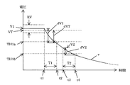
図4は、電圧計の検出電圧すなわち高電圧系回路側の電圧が時間の経過と共に変化する様子の例を示す図である。図4に示すように、車両制御ユニット15が、図2のリレー制御シーケンスに従って、+側リレー12をオフする時(以下、t1時という)までは、図2における高電圧系回路接続状態であり、溶着判定直前の電圧計17によって検出された電圧(インバータ10の端子電圧)vの値は、V1である。バッテリ11の出力電圧は、定格値VTと完全に一致しておらず、かつ予め決められた許容範囲RV内で変動する。+側リレー12が溶着していない場合に、第1の状態に変更すると、すなわち+側リレー12をオフすると、t1時後検出電圧vは徐々に低下する。
The welding detection method according to the second embodiment will be described in detail with reference to FIG.
FIG. 4 is a diagram showing an example of how the detection voltage of the voltmeter, that is, the voltage on the high voltage system circuit side changes with time. As shown in FIG. 4, until the
上述した第1の実施の形態では、予め決められた時間T1が経過した時(以下、t2時という)において、電圧計17の検出電圧vが、予め決められた閾値TH1a以下になったか否かが判断される。
本第2の実施の形態では、t1時から予め決められた時間T1が経過したt2時における、溶着判定直前の電圧計17の検出電圧値V1からの変化量dV1が、予め決められた閾値TH2a以上であるか否かを判定する。そして、溶着判定状態(1)直前の電圧計17の検出電圧値V1からの変化量dV1が、予め決められた閾値TH2a以上のときは、+側リレー12は、溶着していないと判定し、予め決められた閾値TH2a以上でないときは、+側リレー12は、溶着していると判定される。
In the first embodiment described above, whether or not the detected voltage v of the
In the second embodiment, the change amount dV1 from the detected voltage value V1 of the
同様に、−側リレー13についても、溶着判定状態(2)直前の時(以下、t3時という)の電圧計17の検出電圧値V2からの変化量dV2が、t3時から予め決められた時間T2が経過した時(以下、t4時という)において、予め決められた閾値TH2b以上であるか否かに基づいて、−側リレー13が、溶着しているか否かを判定する。
これらの判定のために、上述した図2のフローチャートにおけるS2とS5において、変化量を演算して求め、予め決められた閾値との比較が行われ、予め決められた閾値以上でなければ、S2又はS5においてNOとなって、異常処理が実行される。S2とS5の両方において、変化量が予め決められた閾値以上であれば、YESとなって、正常処理が実行される。異常処理においては、溶着状態を警告すると共に、リレーの接続を禁止し車両を停止する等の処理が行われる。
Similarly, for the
For these determinations, the amount of change is calculated and calculated in S2 and S5 in the flowchart of FIG. 2 described above, and compared with a predetermined threshold value. Alternatively, NO is determined in S5, and the abnormality process is executed. In both S2 and S5, if the amount of change is equal to or greater than a predetermined threshold value, the determination is YES and normal processing is executed. In the abnormal processing, processing such as warning of the welding state and prohibition of connection of the relay to stop the vehicle is performed.
従って、本第2の実施の形態によれば、第1の実施の形態と同様に、溶着検出回路等の検出専用部品を追加することなく、メインリレーの+側リレーと−側リレーのいずれが溶着故障しているかを検出することができる。加えて、溶着判定直前の電圧計の検出電圧値を基準に、変化量を求めて、溶着判定しているので、溶着検出の精度の向上、及び判定時間の短縮化を図ることができる。 Therefore, according to this second embodiment, like the first embodiment, without adding detection dedicated parts such as welding detection circuit, the + side relays of the main relay - either side relay It is possible to detect whether or not welding has failed. In addition, since the amount of change is obtained based on the detected voltage value of the voltmeter immediately before the welding determination and the welding determination is made, it is possible to improve the accuracy of the welding detection and shorten the determination time.
(第3の実施の形態)
第3の実施の形態では、状態変更後、負荷回路側の電圧値が、予め決められた時間経過後において予め決められた値以上変化したか否かの判断を、第1の実施の形態におけるリレー制御シーケンスを用いながら、予め決められた値からの高電圧系回路側の電圧値の変化量を検出し、その変化量が予め決められた閾値以上であったか否かを判定することによって、リレーの溶着を検出する。具体的には、図3のS2及びS5の判断ブロックにおいて、第1の実施の形態における判断内容に代えて、予め決められた時間内における予め決められた値からの変化量を算出し、その変化量が、予め決められら閾値以上であった否かを判定することによって、リレーの溶着判定を行う。
図4を用いて、第3の実施の形態に係る溶着判定方法について詳細に説明する。
図4において、VTは、予め決められた値、例えば、バッテリ11の定格出力値である。第2の実施の形態では、溶着判定直前の電圧計17の検出電圧値V1からの変化量dV1を用いていたが、第3の実施の形態では、バッテリ11の定格出力値等の予め決められた値VTからの変化量dVTを用いる。図4に示すように、t2時において、変化量dVTが、予め決められた閾値TH3a以上になったか否かが判断される。変化量dVTが、予め決められた閾値TH3a以上のときは、+側リレー12は、溶着していないと判定し、予め決められた閾値TH3a以上でないときは、+側リレー12は、溶着していると判定される。
(Third embodiment)
In the third embodiment, after the state change, the determination as to whether or not the voltage value on the load circuit side has changed by a predetermined value or more after a predetermined time has passed is made in the first embodiment. By using the relay control sequence, the amount of change in the voltage value on the high voltage system circuit side from a predetermined value is detected, and it is determined whether the amount of change is equal to or greater than a predetermined threshold. Detects welding. Specifically, in the determination blocks of S2 and S5 in FIG. 3, instead of the determination contents in the first embodiment, the amount of change from a predetermined value within a predetermined time is calculated. By determining whether or not the amount of change is equal to or greater than a predetermined threshold value, relay welding is determined.
The welding determination method according to the third embodiment will be described in detail with reference to FIG.
In FIG. 4, VT is a predetermined value, for example, a rated output value of the battery 11. In the second embodiment, the amount of change dV1 from the detected voltage value V1 of the
同様に、−側リレー13についても、変化量dVTが、t4時において、予め決められた閾値TH3b以上であるか否かに基づいて、−側リレー13が、溶着しているか否かを判定する。
従って、本第3の実施の形態によれば、第1の実施の形態と同様に、溶着検出回路等の検出専用部品を追加することなく、メインリレーの+側リレーと−側リレーのいずれが溶着故障しているかを検出することができる。加えて、予め決められた値を基準に、変化量を求めて、溶着判定しているので、溶着検出の精度の向上、及び判定時間の短縮化を図ることができる。
Similarly, with respect to the
Therefore, according to the third embodiment, as in the first embodiment, any of the positive side relay and the negative side relay of the main relay can be used without adding a dedicated detection part such as a welding detection circuit. It is possible to detect whether a welding failure has occurred. In addition, since the amount of change is obtained based on a predetermined value and welding is determined, the accuracy of welding detection can be improved and the determination time can be shortened.
(第4の実施の形態)
第4の実施の形態では、状態変更後、負荷回路側の電圧値が、予め決められた時間経過後において予め決められた値以上変化したか否かの判断を、第1の実施の形態におけるリレー制御シーケンスを用いながら、高電圧系回路側の電圧値の変化量を検出し、溶着判定直前の高電圧系回路側の電圧値に対する変化量の割合が予め決められた閾値以上であったか否かを判定することによって、リレーの溶着を検出する。具体的には、図3のS2及びS5の判断ブロックにおいて、第1の実施の形態における判断内容に代えて、溶着判定直前の高電圧系回路側の電圧値に対する、予め決められた時間内における高電圧系回路側の電圧値の変化量の割合を算出し、その割合が、予め決められた閾値以上であったか否かを判定することによって、リレーの溶着判定を行う。
図4を用いて、第4の実施の形態に係る溶着判定方法について詳細に説明する。
第2及び第3の実施の形態では、溶着判定直前の電圧計17の検出電圧値V1からの変化量dV1あるいは予め決められた値VTからの変化量dVTを用いていたが、第4の実施の形態では、溶着判定直前の高電圧計回路側の電圧値V1と、変化量との比率を用いる。すなわち、t2時において、溶着判定直前の高電圧計回路側の電圧値V1と、変化量dV1との比率dV1/V1が、予め決められた閾値TH4a以上になったか否かが判断される。比率dV1/V1が、予め決められた閾値TH4a以上のときは、+側リレー12は、溶着していないと判定し、予め決められた閾値TH3a以上でないときは、+側リレー12は、溶着していると判定される。
(Fourth embodiment)
In the fourth embodiment, after the state change, whether or not the voltage value on the load circuit side has changed by a predetermined value or more after a predetermined time has elapsed is determined in the first embodiment. Whether or not the amount of change in the voltage value on the high voltage system circuit side is detected using the relay control sequence, and the ratio of the change amount to the voltage value on the high voltage system circuit side immediately before the welding determination is greater than or equal to a predetermined threshold value. Is detected to detect welding of the relay. Specifically, in the determination blocks of S2 and S5 in FIG. 3, in place of the determination contents in the first embodiment, the voltage value on the high voltage system circuit side immediately before the welding determination is within a predetermined time. The ratio of the amount of change in the voltage value on the high voltage system circuit side is calculated, and it is determined whether or not the ratio is equal to or greater than a predetermined threshold value, thereby performing relay welding determination.
The welding determination method according to the fourth embodiment will be described in detail with reference to FIG.
In the second and third embodiments, the change amount dV1 from the detection voltage value V1 of the
同様に、−側リレー13についても、溶着判定直前の高電圧計回路側の電圧値V2と、変化量dV2との比率dV2/V2が、t4時において、予め決められた閾値TH4b以上であるか否かに基づいて、−側リレー13が、溶着しているか否かを判定する。
従って、本第4の実施の形態によれば、第1の実施の形態と同様に、溶着検出回路等の検出専用部品を追加することなく、メインリレーの+側リレーと−側リレーのいずれが溶着故障しているかを検出することができる。加えて、溶着判定直前の電圧計の検出電圧値に対する変化量の比率を求めて、溶着判定しているので、溶着検出の精度の向上、及び判定時間の短縮化を図ることができる。
Similarly, for the
Therefore, according to the fourth embodiment, like the first embodiment, without adding detection dedicated parts such as welding detection circuit, the + side relays of the main relay - either side relay It is possible to detect whether or not welding has failed. In addition, since the ratio of the change amount with respect to the detected voltage value of the voltmeter immediately before the welding determination is obtained and the welding determination is made, it is possible to improve the accuracy of the welding detection and shorten the determination time.
(第5の実施の形態)
第5の実施の形態では、状態変更後、負荷回路側の電圧値が、予め決められた時間経過後において予め決められた値以上変化したか否かの判断を、第1の実施の形態におけるリレー制御シーケンスを用いながら、高電圧系回路側の電圧値の変化量を検出し、予め決められた値に対するその変化量の割合が予め決められた閾値以上であったか否かを判定することによって、リレーの溶着を検出する。具体的には、図3のS2及びS5の判断ブロックにおいて、第1の実施の形態における判断内容に代えて、予め決められた時間内における予め決められた値に対する高電圧系回路側の電圧値の変化量の割合を算出し、その割合が、予め決められた閾値以上であったか否かを判定することによって、リレーの溶着判定を行う。
図4を用いて、第5の実施の形態に係る溶着判定方法について詳細に説明する。
第4の実施の形態では、溶着判定直前の電圧計17の検出電圧値V1に対する変化量dV1の割合を用いているが、第5の実施の形態では、予め決められた値に対する変化量の割合を用いる。すなわち、t2時において、バッテリの定格出力等の予め決められた値VTと、変化量dVTとの比率dVT/VTが、予め決められた閾値TH5a以上になったか否かが判断される。比率dVT/VTが、予め決められた閾値TH5a以上のときは、+側リレー12は、溶着していないと判定し、予め決められた閾値TH5a以上でないときは、+側リレー12は、溶着していると判定される。
(Fifth embodiment)
In the fifth embodiment, after the state change, the determination as to whether or not the voltage value on the load circuit side has changed by a predetermined value or more after the lapse of a predetermined time is made in the first embodiment. By detecting the amount of change of the voltage value on the high voltage system circuit side while using the relay control sequence, and determining whether the ratio of the amount of change with respect to the predetermined value is equal to or greater than a predetermined threshold, Detects relay welding. Specifically, in the determination blocks of S2 and S5 in FIG. 3, instead of the determination content in the first embodiment, the voltage value on the high voltage system circuit side with respect to a predetermined value within a predetermined time The ratio of the amount of change is calculated, and it is determined whether or not the ratio is equal to or greater than a predetermined threshold value, thereby performing relay welding determination.
The welding determination method according to the fifth embodiment will be described in detail with reference to FIG.
In the fourth embodiment, the ratio of the change amount dV1 to the detected voltage value V1 of the
同様に、−側リレー13についても、予め決められた値に対する変化量の割合が、予め決められた閾値以上であるか否かに基づいて、−側リレー13が、溶着しているか否かを判定する。なお、割合としては、予め決められた値VTに対する、t1時からt4時間における変化量dVT1の比率dVT1/VT、あるいは予め決められた値VTに対する、t3時からt4時間における変化量dVT2の比率dVT2/VTを用いてもよい。
従って、本第5の実施の形態によれば、第1の実施の形態と同様に、溶着検出回路等の検出専用部品を追加することなく、メインリレーの+側リレーと−側リレーのいずれが溶着故障しているかを検出することができる。加えて、予め決められた値を基準に対する変化量の比率を求めて、溶着判定しているので、溶着検出の精度の向上、及び判定時間の短縮化を図ることができる。
Similarly, for the
Therefore, according to the fifth embodiment, as in the first embodiment, any of the positive side relay and the negative side relay of the main relay can be used without adding a detection-dedicated component such as a welding detection circuit. It is possible to detect whether a welding failure has occurred. In addition, since a welding ratio is determined by obtaining a ratio of a change amount with respect to a predetermined value as a reference, it is possible to improve the accuracy of welding detection and shorten the determination time.
(第6の実施の形態)
第6の実施の形態では、状態変更後、負荷回路側の電圧値が、予め決められた時間経過後において予め決められた値以上変化したか否かの判断を、第1の実施の形態におけるリレー制御シーケンスを用いながら、バッテリの電圧を検出する手段を設け、そのバッテリ電圧値と、高電圧系回路側の電圧値とを用いて、溶着判定を行う。具体的には、図3の判定処理中のS2及びS5において、第1の実施の形態における判断内容に代えて、バッテリ11の電圧値と、高電圧系回路側の電圧値との差が演算して求められ、その差あるいはその差のバッテリ電圧値に対する割合が、予め決められた値以上か否かによって、溶着判定を行う。
図5は、第6の実施の形態に係わる車両の駆動系の構成を示す構成図であり、図1の構成と同じ構成要素については、同一の符号を付し説明は省略する。図5において、19は、電圧計であり、バッテリ11の出力電圧を測定する。20は、バッテリ電圧測定ユニットであり、電圧計19が測定したバッテリ電圧値のデータを、データ通信により車両制御ユニット15に送信する。
(Sixth embodiment)
In the sixth embodiment, after the state change, it is determined whether or not the voltage value on the load circuit side has changed by a predetermined value or more after a predetermined time elapses. A means for detecting the voltage of the battery is provided while using the relay control sequence, and welding determination is performed using the battery voltage value and the voltage value on the high voltage system circuit side. Specifically, in S2 and S5 during the determination process of FIG. 3, the difference between the voltage value of the battery 11 and the voltage value on the high voltage system circuit side is calculated instead of the determination contents in the first embodiment. The welding determination is performed depending on whether the difference or the ratio of the difference to the battery voltage value is equal to or greater than a predetermined value.
FIG. 5 is a block diagram showing the configuration of a vehicle drive system according to the sixth embodiment. The same components as those in FIG. 1 are denoted by the same reference numerals, and description thereof is omitted. In FIG. 5,
第6の実施の形態においても、図2のリレー制御シーケンスが用いられ、+側リレー12、−側リレー13及びプリチャージリレー14が、そのリレー制御シーケンスに従って制御される。そして、バッテリ11の電圧値BVと高電圧系回路側の電圧値vとの差dBV、あるいはその差dBVのバッテリ電圧値BVに対する割合dBV/BVが、予め決められた閾値以上か否かによって、溶着判定を行う。
Also in the sixth embodiment, the relay control sequence of FIG. 2 is used, and the +
図4のt2時において、差dBVが予め決められた閾値TH6a以上になったか否か、あるいは割合dB/BVが予め決められた閾値TH7a以上になったか否かが判断される。差dBVが予め決められた閾値TH6a以上のとき、あるいは割合dBV/BVが予め決められた閾値TH7a以上のときは、+側リレー12は、溶着していないと判定し、差dBVが予め決められた閾値TH6a以上でないとき、あるいは割合dB/BVが予め決められた閾値TH7a以上でないときは、+側リレー12は、溶着していると判定される。
At t2 in FIG. 4, it is determined whether or not the difference dBV is equal to or greater than a predetermined threshold TH6a, or whether the ratio dB / BV is equal to or greater than a predetermined threshold TH7a. When the difference dBV is greater than or equal to the predetermined threshold TH6a, or when the ratio dBV / BV is greater than or equal to the predetermined threshold TH7a, it is determined that the +
同様に、−側リレー13についても、差dBV又は割合dBV/BVが、t4時において、予め決められた閾値TH6b以上又は予め決められた閾値TH7b以上であるか否かに基づいて、−側リレー13が、溶着しているか否かを判定する。
従って、本第6の実施の形態によれば、他の実施の形態と同様に、溶着検出回路等の検出専用部品を追加することなく、メインリレーの+側リレーと−側リレーのいずれが溶着故障しているかを検出することができる。加えて、バッテリ電圧との差、あるいはその差のバッテリ電圧に対する比率を求めて、溶着判定しているので、溶着検出の精度の向上を図ることができる。
Similarly, for the
Therefore, according to the sixth embodiment, as with the other embodiments, without adding a detection dedicated parts such as welding detection circuit, the main relay + side relays and - is any side relay It is possible to detect whether a welding failure has occurred. In addition, since the welding determination is performed by obtaining the difference from the battery voltage or the ratio of the difference to the battery voltage, the accuracy of welding detection can be improved.
以上のように、上述した第1から第6の実施の形態によれば、溶着検出専用の検出回路を設けることなく、予め決められたリレー制御シーケンスによるリレーをオン及びオフ制御を行い、負荷回路側の電圧値を測定することによって、+側リレーと−側リレーのいずれが溶着しているかを検出することができる。特に、上述した第1から第6の実施の形態では、制御装置、すなわち車両制御ユニットにおけるプログラムに、上述した溶着判定の処理を実行するためのプログラムを追加するだけでよいので、実装も容易である。 As described above, according to the above-described first to sixth embodiments, the load circuit is configured to perform on / off control of a relay according to a predetermined relay control sequence without providing a detection circuit dedicated to welding detection. By measuring the voltage value on the side, it is possible to detect which of the + side relay and the − side relay is welded. In particular, in the above-described first to sixth embodiments, it is only necessary to add a program for executing the above-described welding determination process to the program in the control device, that is, the vehicle control unit. is there.
なお、以上の実施の形態では、パラレルハイブリッド方式の車両の例で説明したが、上述したリレーの溶着を検出する方法は、シリーズハイブリッド方式、あるいはシリーズ・パラレルハイブリッド方式の車両においても、さらに、ハイブリッド方式でない、電気自動車にも適用できるものである。 In the above embodiment, the parallel hybrid type vehicle has been described as an example. However, the method for detecting the welding of the relay described above is applicable to a series hybrid type or a series / parallel hybrid type vehicle. It can be applied to an electric vehicle that is not a system.
本発明は、上述した実施の形態に限定されるものではなく、本発明の要旨を変えない範囲において、種々の変更、改変等が可能である。 The present invention is not limited to the above-described embodiments, and various changes and modifications can be made without departing from the scope of the present invention.
1・・・1ンジン、2、4・・・モータ、3・・・プラネタリギヤユニット、5・・・動力変換機構、6・・・減速歯車列、7・・・デファレンシャル機構、8・・・駆動軸、9・・・駆動輪、10・・・インバータ、11・・・バッテリ、12・・・+側リレー、13・・・−側リレー、14・・・プリチャージリレー、15・・・車両制御ユニット、16・・・インバータ制御ユニット、17、19・・・電圧計、18・・・抵抗器、20・・・バッテリ電圧測定ユニット
代理人 弁理士 伊 藤 進
DESCRIPTION OF
Claims (7)
前記+側リレーと前記−側リレーが共にオン、かつ前記+側リレーに並列に設けられる、プリチャージリレーとプリチャージ用抵抗器からなる直列回路の前記プリチャージリレーがオフの状態から、前記+側リレーと前記プリチャージリレーがオフ、かつ前記−側リレーがオンの状態である第1の状態に変更する第1の状態変更手段と、
前記第1の状態における前記負荷回路側の電圧値が、予め決められた第1の時間経過後において予め決められた第1の値以上変化しない場合に、前記+側リレーを溶着と判定する第1の溶着判定手段と、
前記第1の状態から、前記+側リレーと前記−側リレーがオフ、かつ前記プリチャージリレーがオンの状態である第2の状態に変更する第2の状態変更手段と、
前記第2の状態における前記負荷回路側の電圧値が、予め決められた第2の時間経過後において予め決められた第2の値以上変化しない場合に、前記−側リレーを溶着と判定する第2の溶着判定手段とを有することを特徴とするリレー溶着検出装置。 Is connected between the load circuit and the battery, and the + side relays being connected to the positive side of the battery, the battery - are connected to the side - a device for detecting the welding of the side relay,
From the state in which the precharge relay of the series circuit composed of a precharge relay and a precharge resistor, which is provided in parallel with the + side relay and the + side relay, is off, the + First state changing means for changing to a first state in which the side relay and the precharge relay are off and the -side relay is on;
Determining a voltage value of the load circuit side in the first state, when no change predetermined first value or more and the first time after the predetermined, and welding the positive side relay First welding determination means;
A second state changing means for changing from the first state to a second state in which the + side relay and the -side relay are off and the precharge relay is on;
When the voltage value on the load circuit side in the second state does not change more than a predetermined second value after a predetermined second time has elapsed, the negative relay is determined to be welded. And a welding determination unit.
前記+側リレーと前記−側リレーが共にオン、かつ前記+側リレーに並列に設けられる、プリチャージリレーとプリチャージ用抵抗器からなる直列回路の前記プリチャージリレーがオフの状態から、前記+側リレーと前記プリチャージリレーがオフ、かつ前記−側リレーがオンの状態である第1の状態に変更し、
前記第1の状態における前記負荷回路側の電圧値が、予め決められた第1の時間経過後において予め決められた第1の値以上変化しない場合に、前記+側リレーを溶着と判定し、
前記第1の状態から、前記+側リレーと前記−側リレーがオフ、かつ前記プリチャージリレーがオンの状態である第2の状態に変更し、
前記第2の状態における前記負荷回路側の電圧値が、予め決められた第2の時間経過後において予め決められた第2の値以上変化しない場合に、前記−側リレーを溶着と判定することを特徴とするリレー溶着検出方法。 Is connected between the load circuit and the battery, and the + side relays being connected to the positive side of the battery, the battery - are connected to the side - a method of detecting the welding of the side relay,
From the state in which the precharge relay of the series circuit composed of a precharge relay and a precharge resistor, which is provided in parallel with the + side relay and the + side relay, is off, the + Change to a first state where the side relay and the precharge relay are off and the -side relay is on,
Voltage value of the load circuit side in the first state, when no change the first value greater than or equal to a predetermined at the first time after the predetermined, the + side relay determines that welding ,
The first state is changed to a second state in which the + side relay and the − side relay are turned off and the precharge relay is turned on,
When the voltage value on the load circuit side in the second state does not change more than a predetermined second value after elapse of a predetermined second time, the negative relay is determined to be welded. A relay welding detection method characterized by the above.
前記ハイブリッド車両におけるエンジン停止指令に基づいて、前記+側リレーと前記−側リレーが共にオン、かつ前記+側リレーに並列に設けられる、プリチャージリレーとプリチャージ用抵抗器からなる直列回路の前記プリチャージリレーがオフの状態から、前記+側リレーと前記プリチャージリレーがオフ、かつ前記−側リレーがオンの状態である第1の状態に変更する第1の状態変更手段と、
前記第1の状態における前記負荷回路側の電圧値が、予め決められた第1の時間経過後において予め決められた第1の値以上変化しない場合に、前記+側リレーを溶着と判定する第1の溶着判定手段と、
前記第1の状態から、前記+側リレーと前記−側リレーがオフ、かつ前記プリチャージリレーがオンの状態である第2の状態に変更する第2の状態変更手段と、
前記第2の状態における前記負荷回路側の電圧値が、予め決められた第2の時間経過後において予め決められた第2の値以上変化しない場合に、前記−側リレーを溶着と判定する第2の溶着判定手段とを有することを特徴とするリレー溶着検出装置。 Is connected between the inverter and the battery for driving the motor in a hybrid vehicle, the + side relays being connected to the positive side of the battery, the battery - are connected to the side - an apparatus for detecting welding of the side relay There,
Based on an engine stop command in the hybrid vehicle, the + side relay and the − side relay are both turned on, and the parallel circuit is provided in parallel with the + side relay. A first state changing means for changing from a state in which the precharge relay is off to a first state in which the + side relay and the precharge relay are off and the -side relay is on;
Determining a voltage value of the load circuit side in the first state, when no change predetermined first value or more and the first time after the predetermined, and welding the positive side relay First welding determination means;
A second state changing means for changing from the first state to a second state in which the + side relay and the -side relay are off and the precharge relay is on;
When the voltage value on the load circuit side in the second state does not change more than a predetermined second value after a predetermined second time has elapsed, the negative relay is determined to be welded. And a welding determination unit.
前記ハイブリッド車両における車両制御停止指令に基づいて、前記+側リレーと前記−側リレーが共にオン、かつ前記+側リレーに並列に設けられる、プリチャージリレーとプリチャージ用抵抗器からなる直列回路の前記プリチャージリレーがオフの状態から、前記+側リレーと前記プリチャージリレーがオフ、かつ前記−側リレーがオンの状態である第1の状態に変更し、
前記第1の状態における前記負荷回路側の電圧値が、予め決められた第1の時間経過後において予め決められた第1の値以上変化しない場合に、前記+側リレーを溶着と判定し、
前記第1の状態から、前記+側リレーと前記−側リレーがオフ、かつ前記プリチャージリレーがオンの状態である第2の状態に変更し、
前記第2の状態における前記負荷回路側の電圧値が、予め決められた第2の時間経過後において予め決められた第2の値以上変化しない場合に、前記−側リレーを溶着と判定することを特徴とするリレー溶着検出方法。 Is connected between the inverter and the battery for driving the motor in a hybrid vehicle, the + side relays being connected to the positive side of the battery, the battery - are connected to the side - in the method for detecting the welding of the side relay There,
Based on a vehicle control stop command in the hybrid vehicle, a series circuit including a precharge relay and a precharge resistor, in which both the + side relay and the − side relay are turned on and provided in parallel to the + side relay. The precharge relay is changed from the off state to the first state in which the + side relay and the precharge relay are off and the-side relay is on.
Voltage value of the load circuit side in the first state, when no change the first value greater than or equal to a predetermined at the first time after the predetermined, the + side relay determines that welding ,
The first state is changed to a second state in which the + side relay and the − side relay are turned off and the precharge relay is turned on,
When the voltage value on the load circuit side in the second state does not change more than a predetermined second value after elapse of a predetermined second time, the negative relay is determined to be welded. A relay welding detection method characterized by the above.
Priority Applications (1)
| Application Number | Priority Date | Filing Date | Title |
|---|---|---|---|
| JP2003352828A JP4570859B2 (en) | 2003-10-10 | 2003-10-10 | Relay welding detection device and relay welding detection method |
Applications Claiming Priority (1)
| Application Number | Priority Date | Filing Date | Title |
|---|---|---|---|
| JP2003352828A JP4570859B2 (en) | 2003-10-10 | 2003-10-10 | Relay welding detection device and relay welding detection method |
Publications (2)
| Publication Number | Publication Date |
|---|---|
| JP2005116485A JP2005116485A (en) | 2005-04-28 |
| JP4570859B2 true JP4570859B2 (en) | 2010-10-27 |
Family
ID=34543629
Family Applications (1)
| Application Number | Title | Priority Date | Filing Date |
|---|---|---|---|
| JP2003352828A Expired - Fee Related JP4570859B2 (en) | 2003-10-10 | 2003-10-10 | Relay welding detection device and relay welding detection method |
Country Status (1)
| Country | Link |
|---|---|
| JP (1) | JP4570859B2 (en) |
Cited By (4)
| Publication number | Priority date | Publication date | Assignee | Title |
|---|---|---|---|---|
| KR101407735B1 (en) | 2012-09-28 | 2014-06-27 | 한국단자공업 주식회사 | Electric vehicle and method for detecting status of PRA pre-charge resistor in the same |
| WO2015137006A1 (en) * | 2014-03-11 | 2015-09-17 | 三菱重工オートモーティブサーマルシステムズ株式会社 | On-state malfunction detection device and method therefor |
| WO2020105995A1 (en) * | 2018-11-22 | 2020-05-28 | 주식회사 엘지화학 | Device and method for checking whether contactor provided in ess is fused |
| WO2022114559A1 (en) * | 2020-11-27 | 2022-06-02 | 주식회사 엘지에너지솔루션 | Relay state management device and operation method therefor |
Families Citing this family (12)
| Publication number | Priority date | Publication date | Assignee | Title |
|---|---|---|---|---|
| JP4305462B2 (en) * | 2006-03-09 | 2009-07-29 | トヨタ自動車株式会社 | Vehicle drive power supply system |
| JP4845779B2 (en) * | 2007-03-12 | 2011-12-28 | 株式会社日立製作所 | DC output circuit with failure detection function |
| JP4900267B2 (en) * | 2008-02-01 | 2012-03-21 | トヨタ自動車株式会社 | Method for determining welding of power supply device and relay |
| US7966110B2 (en) * | 2008-03-05 | 2011-06-21 | GM Global Technology Operations LLC | High-voltage vehicle fault detection method and apparatus |
| US8421409B2 (en) | 2008-09-19 | 2013-04-16 | Toyota Jidosha Kabushiki Kaisha | Noncontact power receiving apparatus for electrically-powered vehicle and vehicle including the same |
| FR2948461B1 (en) * | 2009-07-24 | 2011-07-01 | Renault Sa | METHOD FOR DIAGNOSING THE OPERATION OF A DEVICE FOR CUTTING AND CONNECTING A BATTERY TO A MOTOR VEHICLE EDGE NETWORK |
| JP2012005174A (en) * | 2010-06-14 | 2012-01-05 | Toyota Motor Corp | Electric power supply apparatus of vehicle |
| JP5796445B2 (en) * | 2011-10-05 | 2015-10-21 | アイシン精機株式会社 | Vehicle power supply device |
| US9434261B2 (en) | 2011-10-17 | 2016-09-06 | Robert Bosch Gmbh | Welded contactor checking systems and methods |
| JP6417892B2 (en) * | 2014-11-21 | 2018-11-07 | 三菱自動車工業株式会社 | Contactor failure determination method and contactor failure determination device |
| KR101664745B1 (en) | 2015-09-25 | 2016-10-24 | 현대자동차주식회사 | Method for detecting fusion of relay of battery |
| US10877095B2 (en) * | 2016-09-07 | 2020-12-29 | Panasonic Intellectual Property Management Co., Ltd. | Power storage system |
Family Cites Families (2)
| Publication number | Priority date | Publication date | Assignee | Title |
|---|---|---|---|---|
| JP3769843B2 (en) * | 1996-11-07 | 2006-04-26 | 日産自動車株式会社 | High-voltage relay diagnostic device for electric vehicles |
| JP2003102101A (en) * | 2001-09-25 | 2003-04-04 | Suzuki Motor Corp | Power supply control device for electric vehicles |
-
2003
- 2003-10-10 JP JP2003352828A patent/JP4570859B2/en not_active Expired - Fee Related
Cited By (7)
| Publication number | Priority date | Publication date | Assignee | Title |
|---|---|---|---|---|
| KR101407735B1 (en) | 2012-09-28 | 2014-06-27 | 한국단자공업 주식회사 | Electric vehicle and method for detecting status of PRA pre-charge resistor in the same |
| WO2015137006A1 (en) * | 2014-03-11 | 2015-09-17 | 三菱重工オートモーティブサーマルシステムズ株式会社 | On-state malfunction detection device and method therefor |
| JP2015173019A (en) * | 2014-03-11 | 2015-10-01 | 三菱重工オートモーティブサーマルシステムズ株式会社 | On-failure detection device and method thereof |
| WO2020105995A1 (en) * | 2018-11-22 | 2020-05-28 | 주식회사 엘지화학 | Device and method for checking whether contactor provided in ess is fused |
| US11307255B2 (en) | 2018-11-22 | 2022-04-19 | Lg Energy Solution, Ltd. | Device and method for checking whether contactor provided in ESS is welded |
| WO2022114559A1 (en) * | 2020-11-27 | 2022-06-02 | 주식회사 엘지에너지솔루션 | Relay state management device and operation method therefor |
| US12276700B2 (en) | 2020-11-27 | 2025-04-15 | Lg Energy Solution, Ltd. | Relay state management apparatus and operating method thereof |
Also Published As
| Publication number | Publication date |
|---|---|
| JP2005116485A (en) | 2005-04-28 |
Similar Documents
| Publication | Publication Date | Title |
|---|---|---|
| JP4570859B2 (en) | Relay welding detection device and relay welding detection method | |
| JP6417892B2 (en) | Contactor failure determination method and contactor failure determination device | |
| JP5450144B2 (en) | Power supply device for vehicle and vehicle equipped with this power supply device | |
| JP3926519B2 (en) | Hybrid vehicle | |
| US8194367B2 (en) | Accumulation device | |
| JP2009227044A (en) | Deteriorated state decision method and device for electricity accumulation device in hybrid construction machine | |
| JPH0919003A (en) | Deterioration discriminating device for capacitor in motor-driven vehicle | |
| WO2008126629A1 (en) | Electric vehicle | |
| KR101846907B1 (en) | Apparatus and method for determining faulty of engine clutch | |
| JP6992426B2 (en) | Vehicle charging device | |
| JP4981773B2 (en) | Industrial vehicle clutch failure diagnosis method and apparatus | |
| JP5109743B2 (en) | Power system, control method therefor, and vehicle | |
| CN102485544B (en) | Torque sensor fault detection device and method | |
| JP5515834B2 (en) | Drive device | |
| CN108515879A (en) | A kind of electric vehicle shift control system and its control method | |
| JP2013207926A (en) | Braking control device | |
| CN113386733B (en) | Hybrid vehicle drive system | |
| CN102267457B (en) | Method and system for controlling motor torque in hybrid vehicles | |
| CN103101439A (en) | Electric vehicle and method of diagnosing current sensor | |
| JP6077762B2 (en) | Hydraulic abnormality diagnosis and control method for hybrid vehicle transmission | |
| JP2009060695A (en) | Alarm apparatus for hybrid electric vehicle | |
| JP2004303691A (en) | Relay welding determination apparatus and welding determination method | |
| JP2002291149A (en) | Motor control device | |
| JP6121821B2 (en) | Power system | |
| JP2022124404A (en) | Control device for vehicle |
Legal Events
| Date | Code | Title | Description |
|---|---|---|---|
| A621 | Written request for application examination |
Free format text: JAPANESE INTERMEDIATE CODE: A621 Effective date: 20061005 |
|
| A977 | Report on retrieval |
Free format text: JAPANESE INTERMEDIATE CODE: A971007 Effective date: 20090220 |
|
| A131 | Notification of reasons for refusal |
Free format text: JAPANESE INTERMEDIATE CODE: A131 Effective date: 20090310 |
|
| A521 | Request for written amendment filed |
Free format text: JAPANESE INTERMEDIATE CODE: A523 Effective date: 20090507 |
|
| A131 | Notification of reasons for refusal |
Free format text: JAPANESE INTERMEDIATE CODE: A131 Effective date: 20091201 |
|
| A521 | Request for written amendment filed |
Free format text: JAPANESE INTERMEDIATE CODE: A523 Effective date: 20100128 |
|
| TRDD | Decision of grant or rejection written | ||
| A01 | Written decision to grant a patent or to grant a registration (utility model) |
Free format text: JAPANESE INTERMEDIATE CODE: A01 Effective date: 20100803 |
|
| A01 | Written decision to grant a patent or to grant a registration (utility model) |
Free format text: JAPANESE INTERMEDIATE CODE: A01 |
|
| A61 | First payment of annual fees (during grant procedure) |
Free format text: JAPANESE INTERMEDIATE CODE: A61 Effective date: 20100811 |
|
| FPAY | Renewal fee payment (event date is renewal date of database) |
Free format text: PAYMENT UNTIL: 20130820 Year of fee payment: 3 |
|
| R150 | Certificate of patent or registration of utility model |
Ref document number: 4570859 Country of ref document: JP Free format text: JAPANESE INTERMEDIATE CODE: R150 Free format text: JAPANESE INTERMEDIATE CODE: R150 |
|
| R250 | Receipt of annual fees |
Free format text: JAPANESE INTERMEDIATE CODE: R250 |
|
| R250 | Receipt of annual fees |
Free format text: JAPANESE INTERMEDIATE CODE: R250 |
|
| S531 | Written request for registration of change of domicile |
Free format text: JAPANESE INTERMEDIATE CODE: R313531 |
|
| R350 | Written notification of registration of transfer |
Free format text: JAPANESE INTERMEDIATE CODE: R350 |
|
| R250 | Receipt of annual fees |
Free format text: JAPANESE INTERMEDIATE CODE: R250 |
|
| R250 | Receipt of annual fees |
Free format text: JAPANESE INTERMEDIATE CODE: R250 |
|
| S533 | Written request for registration of change of name |
Free format text: JAPANESE INTERMEDIATE CODE: R313533 |
|
| R350 | Written notification of registration of transfer |
Free format text: JAPANESE INTERMEDIATE CODE: R350 |
|
| R250 | Receipt of annual fees |
Free format text: JAPANESE INTERMEDIATE CODE: R250 |
|
| R250 | Receipt of annual fees |
Free format text: JAPANESE INTERMEDIATE CODE: R250 |
|
| R250 | Receipt of annual fees |
Free format text: JAPANESE INTERMEDIATE CODE: R250 |
|
| R250 | Receipt of annual fees |
Free format text: JAPANESE INTERMEDIATE CODE: R250 |
|
| R250 | Receipt of annual fees |
Free format text: JAPANESE INTERMEDIATE CODE: R250 |
|
| R250 | Receipt of annual fees |
Free format text: JAPANESE INTERMEDIATE CODE: R250 |
|
| LAPS | Cancellation because of no payment of annual fees |