JP6077762B2 - Hydraulic abnormality diagnosis and control method for hybrid vehicle transmission - Google Patents
Hydraulic abnormality diagnosis and control method for hybrid vehicle transmission Download PDFInfo
- Publication number
- JP6077762B2 JP6077762B2 JP2012133247A JP2012133247A JP6077762B2 JP 6077762 B2 JP6077762 B2 JP 6077762B2 JP 2012133247 A JP2012133247 A JP 2012133247A JP 2012133247 A JP2012133247 A JP 2012133247A JP 6077762 B2 JP6077762 B2 JP 6077762B2
- Authority
- JP
- Japan
- Prior art keywords
- mode
- hydraulic pressure
- ring gear
- speed
- vehicle
- Prior art date
- Legal status (The legal status is an assumption and is not a legal conclusion. Google has not performed a legal analysis and makes no representation as to the accuracy of the status listed.)
- Expired - Fee Related
Links
Images


Classifications
-
- B—PERFORMING OPERATIONS; TRANSPORTING
- B60—VEHICLES IN GENERAL
- B60W—CONJOINT CONTROL OF VEHICLE SUB-UNITS OF DIFFERENT TYPE OR DIFFERENT FUNCTION; CONTROL SYSTEMS SPECIALLY ADAPTED FOR HYBRID VEHICLES; ROAD VEHICLE DRIVE CONTROL SYSTEMS FOR PURPOSES NOT RELATED TO THE CONTROL OF A PARTICULAR SUB-UNIT
- B60W10/00—Conjoint control of vehicle sub-units of different type or different function
- B60W10/10—Conjoint control of vehicle sub-units of different type or different function including control of change-speed gearings
- B60W10/101—Infinitely variable gearings
- B60W10/105—Infinitely variable gearings of electric type
-
- F—MECHANICAL ENGINEERING; LIGHTING; HEATING; WEAPONS; BLASTING
- F16—ENGINEERING ELEMENTS AND UNITS; GENERAL MEASURES FOR PRODUCING AND MAINTAINING EFFECTIVE FUNCTIONING OF MACHINES OR INSTALLATIONS; THERMAL INSULATION IN GENERAL
- F16H—GEARING
- F16H61/00—Control functions within control units of change-speed- or reversing-gearings for conveying rotary motion ; Control of exclusively fluid gearing, friction gearing, gearings with endless flexible members or other particular types of gearing
- F16H61/04—Smoothing ratio shift
-
- B—PERFORMING OPERATIONS; TRANSPORTING
- B60—VEHICLES IN GENERAL
- B60K—ARRANGEMENT OR MOUNTING OF PROPULSION UNITS OR OF TRANSMISSIONS IN VEHICLES; ARRANGEMENT OR MOUNTING OF PLURAL DIVERSE PRIME-MOVERS IN VEHICLES; AUXILIARY DRIVES FOR VEHICLES; INSTRUMENTATION OR DASHBOARDS FOR VEHICLES; ARRANGEMENTS IN CONNECTION WITH COOLING, AIR INTAKE, GAS EXHAUST OR FUEL SUPPLY OF PROPULSION UNITS IN VEHICLES
- B60K6/00—Arrangement or mounting of plural diverse prime-movers for mutual or common propulsion, e.g. hybrid propulsion systems comprising electric motors and internal combustion engines ; Control systems therefor, i.e. systems controlling two or more prime movers, or controlling one of these prime movers and any of the transmission, drive or drive units Informative references: mechanical gearings with secondary electric drive F16H3/72; arrangements for handling mechanical energy structurally associated with the dynamo-electric machine H02K7/00; machines comprising structurally interrelated motor and generator parts H02K51/00; dynamo-electric machines not otherwise provided for in H02K see H02K99/00
- B60K6/20—Arrangement or mounting of plural diverse prime-movers for mutual or common propulsion, e.g. hybrid propulsion systems comprising electric motors and internal combustion engines ; Control systems therefor, i.e. systems controlling two or more prime movers, or controlling one of these prime movers and any of the transmission, drive or drive units Informative references: mechanical gearings with secondary electric drive F16H3/72; arrangements for handling mechanical energy structurally associated with the dynamo-electric machine H02K7/00; machines comprising structurally interrelated motor and generator parts H02K51/00; dynamo-electric machines not otherwise provided for in H02K see H02K99/00 the prime-movers consisting of electric motors and internal combustion engines, e.g. HEVs
- B60K6/42—Arrangement or mounting of plural diverse prime-movers for mutual or common propulsion, e.g. hybrid propulsion systems comprising electric motors and internal combustion engines ; Control systems therefor, i.e. systems controlling two or more prime movers, or controlling one of these prime movers and any of the transmission, drive or drive units Informative references: mechanical gearings with secondary electric drive F16H3/72; arrangements for handling mechanical energy structurally associated with the dynamo-electric machine H02K7/00; machines comprising structurally interrelated motor and generator parts H02K51/00; dynamo-electric machines not otherwise provided for in H02K see H02K99/00 the prime-movers consisting of electric motors and internal combustion engines, e.g. HEVs characterised by the architecture of the hybrid electric vehicle
- B60K6/44—Series-parallel type
- B60K6/445—Differential gearing distribution type
-
- B—PERFORMING OPERATIONS; TRANSPORTING
- B60—VEHICLES IN GENERAL
- B60W—CONJOINT CONTROL OF VEHICLE SUB-UNITS OF DIFFERENT TYPE OR DIFFERENT FUNCTION; CONTROL SYSTEMS SPECIALLY ADAPTED FOR HYBRID VEHICLES; ROAD VEHICLE DRIVE CONTROL SYSTEMS FOR PURPOSES NOT RELATED TO THE CONTROL OF A PARTICULAR SUB-UNIT
- B60W20/00—Control systems specially adapted for hybrid vehicles
- B60W20/50—Control strategies for responding to system failures, e.g. for fault diagnosis, failsafe operation or limp mode
-
- F—MECHANICAL ENGINEERING; LIGHTING; HEATING; WEAPONS; BLASTING
- F16—ENGINEERING ELEMENTS AND UNITS; GENERAL MEASURES FOR PRODUCING AND MAINTAINING EFFECTIVE FUNCTIONING OF MACHINES OR INSTALLATIONS; THERMAL INSULATION IN GENERAL
- F16H—GEARING
- F16H61/00—Control functions within control units of change-speed- or reversing-gearings for conveying rotary motion ; Control of exclusively fluid gearing, friction gearing, gearings with endless flexible members or other particular types of gearing
- F16H61/0021—Generation or control of line pressure
- F16H61/0025—Supply of control fluid; Pumps therefore
- F16H61/0031—Supply of control fluid; Pumps therefore using auxiliary pumps, e.g. pump driven by a different power source than the engine
-
- F—MECHANICAL ENGINEERING; LIGHTING; HEATING; WEAPONS; BLASTING
- F16—ENGINEERING ELEMENTS AND UNITS; GENERAL MEASURES FOR PRODUCING AND MAINTAINING EFFECTIVE FUNCTIONING OF MACHINES OR INSTALLATIONS; THERMAL INSULATION IN GENERAL
- F16H—GEARING
- F16H61/00—Control functions within control units of change-speed- or reversing-gearings for conveying rotary motion ; Control of exclusively fluid gearing, friction gearing, gearings with endless flexible members or other particular types of gearing
- F16H61/04—Smoothing ratio shift
- F16H61/06—Smoothing ratio shift by controlling rate of change of fluid pressure
-
- B—PERFORMING OPERATIONS; TRANSPORTING
- B60—VEHICLES IN GENERAL
- B60Y—INDEXING SCHEME RELATING TO ASPECTS CROSS-CUTTING VEHICLE TECHNOLOGY
- B60Y2200/00—Type of vehicle
- B60Y2200/90—Vehicles comprising electric prime movers
- B60Y2200/92—Hybrid vehicles
-
- Y—GENERAL TAGGING OF NEW TECHNOLOGICAL DEVELOPMENTS; GENERAL TAGGING OF CROSS-SECTIONAL TECHNOLOGIES SPANNING OVER SEVERAL SECTIONS OF THE IPC; TECHNICAL SUBJECTS COVERED BY FORMER USPC CROSS-REFERENCE ART COLLECTIONS [XRACs] AND DIGESTS
- Y02—TECHNOLOGIES OR APPLICATIONS FOR MITIGATION OR ADAPTATION AGAINST CLIMATE CHANGE
- Y02T—CLIMATE CHANGE MITIGATION TECHNOLOGIES RELATED TO TRANSPORTATION
- Y02T10/00—Road transport of goods or passengers
- Y02T10/60—Other road transportation technologies with climate change mitigation effect
- Y02T10/62—Hybrid vehicles
Description
本発明は、ハイブリッド車両用変速機の油圧異常診断および制御方法に関し、より詳細には、ハイブリッド車両用変速機に異物による障害が生じたとき、油圧の異常可否を判断して迅速に異物を除去できるようにするハイブリッド車両用変速機の油圧異常診断および制御方法に関する。 More particularly, the present invention relates to a method for diagnosing and controlling a hydraulic pressure abnormality of a hybrid vehicle transmission, and more specifically, when a failure due to a foreign matter occurs in the hybrid vehicle transmission, the foreign matter is quickly removed by determining whether the hydraulic pressure is abnormal. The present invention relates to a hydraulic abnormality diagnosis and control method for a hybrid vehicle transmission.
エンジンと、モータジェネレータおよび遊星ギヤ装置を組み合わせて構成されたハイブリッド変速機を搭載したハイブリッド車両は、主に出発および低速区間ではモータのみで駆動する電気車モード走行をし、この後に車両速度が増したときに、変速機を電気可変トランスミッション(EVT;Electrically Variable Transmission)で作用するようにし、エンジンの動力とモータの動力を効率よく用いることができるようにする動力分岐モードで走行することができる。また、車両の動力性能をより高めるために、既存の変速機のように固定段ギヤ比を用いるようにできる。
このような概念に基づくシステムは、アイドルストップ機能と回生制動の極大化、および車両の燃費、動力性能を改善するように開発されている。
A hybrid vehicle equipped with a hybrid transmission configured by combining an engine, a motor generator, and a planetary gear device runs in an electric vehicle mode driven only by a motor mainly in the departure and low speed sections, and thereafter the vehicle speed increases. In this case, the transmission can be operated in an electric variable transmission (EVT) so that the engine power and the motor power can be used efficiently, so that the transmission can operate with an electric variable transmission (EVT). Further, in order to further improve the power performance of the vehicle, a fixed stage gear ratio can be used as in an existing transmission.
A system based on such a concept has been developed to maximize the idle stop function and regenerative braking, and to improve the fuel efficiency and power performance of the vehicle.
しかし、現在の一般的なガソリン車両と同じように、ハイブリッド専用車用変速機も油圧異常発生時に変速衝撃や変速異常現象などが現れるが、このような場合にはリアルタイムで油圧計測が不可能であるため、問題発生時に迅速に診断および対処することができる特別な方法がない。車両変速機については、油圧の異常を検出する装置に提案がある〔例えば、特許文献1、2〕。
However, as with current general gasoline vehicles, gear shift shocks and gear shifting abnormalities appear when a hydraulic pressure abnormality occurs in a hybrid dedicated vehicle transmission. In such a case, oil pressure measurement is impossible in real time. As such, there is no special way to quickly diagnose and deal with problems. Regarding vehicle transmissions, there are proposals for devices that detect an abnormality in hydraulic pressure [for example,
従来技術では、問題発生時の変速機アセンブリの油圧性能試験を行って問題現象を再現し、分解後の古品分析によって原因分析および改善を行っていた。従って、従来技術の場合、顧客が運転する最中にこのような問題が発生した場合には即刻診断と対処が不可能であり、その場で変速機分解などが不可能であるため、顧客の安全に深刻な危険を招くようになるという問題がある。 In the prior art, the hydraulic performance test of the transmission assembly at the time of the problem was performed to reproduce the problem phenomenon, and the cause analysis and improvement were performed by analyzing the used items after disassembly. Therefore, in the case of the conventional technology, if such a problem occurs while the customer is driving, it is impossible to immediately diagnose and deal with it, and it is impossible to disassemble the transmission on the spot. There is a problem that it will pose a serious danger to safety.
上記の問題を解決するためになされた本発明の目的は、ハイブリッド車両用変速機の異常現象を迅速かつ正確に判断することによって運転手が迅速に問題を処理できるように誘導し、これによって運転手の安全性を向上させることができるハイブリッド車両用変速機の油圧異常診断および制御方法を提供することにある。 The object of the present invention, which has been made to solve the above problems, is to guide the driver to quickly handle the problem by quickly and accurately judging the abnormal phenomenon of the hybrid vehicle transmission, thereby driving the vehicle. An object of the present invention is to provide a hydraulic pressure abnormality diagnosis and control method for a hybrid vehicle transmission capable of improving hand safety.
上記の課題を解決するためになされた本発明は、エンジン(ENGINE)と、第1モータジェネレータ(MG1)と、第2モータジェネレータ(MG2)と、第1差動ギヤ装置(1)と、第2差動ギヤ装置(3)と、出力要素(Output)と、を有し、第1差動ギヤ装置(1)及び第2差動ギヤ装置(3)は、それぞれ遊星ギヤ装置からなり、第1差動ギヤ装置(1)は、第1サンギヤ(S1)、第1キャリア(C1)、および第1リングギヤ(R1)からなり、第2差動ギヤ装置(3)は、第2サンギヤ(S2)、第2キャリア(C2)、および第2リングギヤ(R2)からなり、第1サンギヤ(S1)は、第2サンギヤ(S2)に常に連結し、第1キャリア(C1)は第2クラッチ(CL2)を介して第2リングギヤ(R2)に連結するとともにエンジン(ENGINE)と直接に連結し、第1リングギヤ(R1)は、第1モータジェネレータ(MG1)に常に連結し、第2サンギヤ(S2)は第2モータジェネレータ(MG2)に常に連結し、第2キャリア(C2)は、出力要素(Output)に常に連結し、第2ブレーキ(BK2)が、第2リングギヤ(R2)の回転を拘束できるように設置され、第1クラッチ(CL1)が、第1キャリア(C1)と第1リングギヤ(R1)の間を選択的に連結できるように設置され、第1ブレーキ(BK1)が、第1リングギヤ(R1)の回転を拘束できるように設置されたハイブリッド車両の電気可変トランスミッションにおいて、第2ブレーキ(BK2)を解除し。第2クラッチ(CL2)を締結して第1モードから第2モードに変換するマルチモード電気可変トランスミッションからなるハイブリッド車両用変速機の油圧異常診断および制御方法であって、
前記第1モードから第2モードに変換するか否かを判断する段階と、第2モードに変換する場合、これによって締結したクラッチに油圧が発生するか否かおよび油圧が予め設定された値を超過して発生するか否かを判断する段階と、判断において、クラッチに油圧が発生しなかったりまたは油圧が予め設定された値を超過して発生したりする場合に車両異常として判断する段階と、を含んで構成され、
前記第2モードの第2リングギヤの速度(ω R2 )が負の値を有し、第2モードの第2モータジェネレータの速度(ω MG2 )の時間による変化率(傾き)が正の値を有する場合、油圧が発生しないものと判断することを特徴とする。
The present invention made to solve the above-described problems includes an engine (ENGINE), a first motor generator (MG1), a second motor generator (MG2), a first differential gear device (1), 2 differential gear device (3) and an output element (Output), the first differential gear device (1) and the second differential gear device (3) are each composed of a planetary gear device, The first differential gear device (1) includes a first sun gear (S1), a first carrier (C1), and a first ring gear (R1), and the second differential gear device (3) includes a second sun gear (S2). ), A second carrier (C2), and a second ring gear (R2). The first sun gear (S1) is always connected to the second sun gear (S2), and the first carrier (C1) is connected to the second clutch (CL2). ) To the second ring gear (R2) via The first ring gear (R1) is always connected to the first motor generator (MG1), and the second sun gear (S2) is always connected to the second motor generator (MG2). The second carrier (C2) is always connected to the output element (Output), the second brake (BK2) is installed so as to restrain the rotation of the second ring gear (R2), and the first clutch (CL1) is The first carrier (C1) and the first ring gear (R1) are installed so as to be selectively connected, and the first brake (BK1) is installed so as to restrain the rotation of the first ring gear (R1). Release the second brake (BK2) in the electric variable transmission of the hybrid vehicle. A hydraulic abnormality diagnosis and control method for a hybrid vehicle transmission comprising a multi-mode electric variable transmission that engages a second clutch (CL2) to convert from a first mode to a second mode ,
The step of determining whether to convert from the first mode to the second mode, and, when converting to the second mode, whether or not the hydraulic pressure is generated in the clutch that is engaged thereby, and the hydraulic pressure is set in advance. A step of determining whether or not it occurs in excess, and a step of determining that the vehicle is abnormal when the hydraulic pressure is not generated in the clutch or when the hydraulic pressure exceeds a preset value. Comprising, and
The speed (ω R2 ) of the second ring gear in the second mode has a negative value, and the rate of change (slope) with time of the speed (ω MG2 ) of the second motor generator in the second mode has a positive value. In this case, it is determined that no hydraulic pressure is generated .
このとき、第2モードの第2リングギヤの速度(ωR2)が負の値を有し、第2モードの第2モータジェネレータの速度(ωMG2)の時間による変化率(傾き)が正の値を有する場合、油圧が発生しないものと判断することができる。 At this time, the speed (ω R2 ) of the second ring gear in the second mode has a negative value, and the rate of change (slope) with time of the speed (ω MG2 ) of the second motor generator in the second mode is a positive value. It can be determined that no hydraulic pressure is generated.
また、第2モードの第2リングギヤの速度(ωR2)の時間による変化率(傾き)が予め設定された正常基準範囲の最大値(Acriteria−max)よりも大きく、第2モードの第2モータジェネレータの速度(ωMG2)の時間による変化率(傾き)が予め設定された正常基準範囲の最小値(Bcriteria−min)よりも小さい場合、油圧が予め設定された値を超過するものと判断することができる。 Further, the rate of change (inclination) with time of the speed (ω R2 ) of the second ring gear in the second mode is greater than a preset maximum value (A criteria-max ) of the normal reference range, When the rate of change (inclination) of the motor generator speed (ω MG2 ) with time is smaller than the preset minimum value (B criteria -min ) of the normal reference range, the hydraulic pressure exceeds the preset value. Judgment can be made.
上記で車両異常と判断する場合、直接制御ソレノイドバルブを強制駆動する段階をさらに含むことができる。
強制駆動後に車両が走行する場合には、車両の異常可否を再判断する段階をさらに含むことができる。そして、その再判断において、車両の異常と判断される場合、電気可変トランスミッションのモードを第1モードに固定する段階をさらに含むことができる。
When it is determined that the vehicle is abnormal as described above, it may further include a step of forcibly driving the direct control solenoid valve.
When the vehicle travels after forcible driving, it may further include a step of re-determining whether the vehicle is abnormal. In the re-determination, when it is determined that the vehicle is abnormal, it may further include a step of fixing the mode of the electric variable transmission to the first mode.
本発明のハイブリッド車両用変速機の油圧異常診断および制御方法によれば、迅速かつ正確に変速の異常可否を診断し、これによって異物を除去するように制御する。これにより、運転の安全性が向上する。 According to the hydraulic pressure abnormality diagnosis and control method for a hybrid vehicle transmission according to the present invention, it is quickly and accurately diagnosed as to whether or not a shift abnormality is present, and thereby control is performed to remove foreign matter. As a result, driving safety is improved.
以下、本発明のハイブリッド車両用変速機の油圧異常診断および制御方法について、好ましい実施形態を挙げ、添付の図面を参照しながら詳細に説明する。
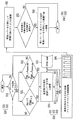
図1は、本発明に係るハイブリッド車両用変速機の油圧異常診断および制御方法のフローチャートである。図2は、ハイブリッド車両の構成図である。
Hereinafter, the hydraulic abnormality diagnosis and control method for a hybrid vehicle transmission according to the present invention will be described in detail with reference to the accompanying drawings by way of preferred embodiments.
FIG. 1 is a flowchart of a hydraulic pressure abnormality diagnosis and control method for a hybrid vehicle transmission according to the present invention. FIG. 2 is a configuration diagram of the hybrid vehicle.
図1および図2を参照すると、ハイブリッド車両用変速機の油圧異常診断および制御方法は、第1モードと第2モードのマルチモード電気可変トランスミッションからなるハイブリッド車両用変速機の油圧異常診断および制御方法であって、第1モードから第2モードに変換するか否かを判断する段階(S10)と、第2モードに変換する場合、第2モードに連結するクラッチに油圧が発生しないか否かおよび油圧が予め設定された値を超過して発生するか否かを判断する段階(S20)と、この判断において、クラッチに油圧が発生しなかったりまたは油圧が予め設定された値を超過して発生したりする場合、車両異常として判断する段階(S30)と、車両異常として判断する場合、直接制御ソレノイドバルブを強制駆動する段階(S40)と、強制駆動後に車両が走行する場合、車両の異常可否を再判断する段階(S50)と、再判断において異常として判断された場合、第1モードに固定する段階(S60)を含んで構成されている。 Referring to FIGS. 1 and 2, a hydraulic vehicle abnormality diagnosis and control method for a hybrid vehicle transmission includes a first mode and a second mode multi-mode electric variable transmission hydraulic pressure abnormality diagnosis and control method. The step of determining whether to convert from the first mode to the second mode (S10), and whether to convert to the second mode, whether or not hydraulic pressure is generated in the clutch connected to the second mode, and In step S20, it is determined whether or not the hydraulic pressure exceeds a preset value. In this determination, no hydraulic pressure is generated in the clutch or the hydraulic pressure exceeds a preset value. If it is determined that the vehicle is abnormal (S30), and if it is determined that the vehicle is abnormal, the control solenoid valve is forcibly driven (S4). ), When the vehicle travels after forcible driving, a step of re-determining whether the vehicle is abnormal (S50), and when it is determined as abnormal in the re-determination, a step of fixing to the first mode (S60) is included. Has been.
まず、ハイブリッド車両用変速機において、ハイブリッド車両の制御部では、第1電気車モードから第2電気車モードに変換するか否かを判断する(S10)。 First, in the hybrid vehicle transmission, the control unit of the hybrid vehicle determines whether or not to convert from the first electric vehicle mode to the second electric vehicle mode (S10).
本発明のハイブリッド車両用変速機の油圧異常診断および制御方法に適用されるハイブリッド車両は、第1モード(EVT1)と第2モード(EVT2)のマルチモード電気可変トランスミッション(Electrically Variable Transmission)で構成される。 A hybrid vehicle applied to a hydraulic pressure abnormality diagnosis and control method for a hybrid vehicle transmission according to the present invention includes a first mode (EVT1) and a second mode (EVT2) multi-mode electric variable transmission (Electrically Variable Transmission). The
本発明に係るハイブリッド車両は、図2に示すように、第1モータジェネレータ(MG1)と第2モータジェネレータ(MG2)それぞれに連結する第1差動ギヤ装置1と第2差動ギヤ装置3を有している。
As shown in FIG. 2, the hybrid vehicle according to the present invention includes a first
第1差動ギヤ装置1および第2差動ギヤ装置3はそれぞれ遊星ギヤ装置からなり、第1差動ギヤ装置1は第1サンギヤ(S1)、第1キャリア(C1)、および第1リングギヤ(R1)からなり、第2差動ギヤ装置3は第2サンギヤ(S2)、第2キャリア(C2)、および第2リングギヤ(R2)からなっている。
もちろん、第1差動ギヤ装置1と第2差動ギヤ装置3は、遊星ギヤ装置だけでなく、ベベルギヤなどのようなギヤを使用し、少なくともいずれか1つのギヤの回転速度が常に異なる2つのギヤの加重平均速度をなすようにする別のギヤ装置でも実現が可能である。
Each of the first
Of course, the first
図2に示すように、第1サンギヤ(S1)は、第2サンギヤ(S2)に常に連結し、第1キャリア(C1)は第2クラッチ(CL2)を介して第2リングギヤ(R2)に連結し、エンジン(ENGINE)と直接に連結する。 As shown in FIG. 2, the first sun gear (S1) is always connected to the second sun gear (S2), and the first carrier (C1) is connected to the second ring gear (R2) via the second clutch (CL2). And directly connected to the engine (ENGINE).
第1リングギヤ(R1)は、第1モータジェネレータ(MG1)に常に連結し、第2サンギヤ(S2)は第2モータジェネレータ(MG2)に常に連結し、第2キャリア(C2)は出力要素(Output)に連結する。
第2ブレーキ(BK2)は、第2リングギヤ(R2)の回転を拘束できるように設置される。
The first ring gear (R1) is always connected to the first motor generator (MG1), the second sun gear (S2) is always connected to the second motor generator (MG2), and the second carrier (C2) is connected to the output element (Output). ).
The second brake (BK2) is installed so as to restrain the rotation of the second ring gear (R2).
一方、第1クラッチ(CL1)は、第1キャリア(C1)と第1リングギヤ(R1)の間を選択的に連結できるように設置され、第1ブレーキ(BK1)は、第1リングギヤ(R1)の回転を拘束できるように設置される。 Meanwhile, the first clutch (CL1) is installed so as to selectively connect the first carrier (C1) and the first ring gear (R1), and the first brake (BK1) is connected to the first ring gear (R1). It is installed so that the rotation of the can be restricted.
このようなハイブリッド車両の電気可変トランスミッションが第1モード(EVT1)から第2モード(EVT2)に変換する場合には、図2に示す第2ブレーキ(BK2)を解除して第2クラッチ(CL2)と締結するようになる。 When the electric variable transmission of such a hybrid vehicle changes from the first mode (EVT1) to the second mode (EVT2), the second brake (BK2) shown in FIG. 2 is released and the second clutch (CL2) is released. It comes to conclude with.
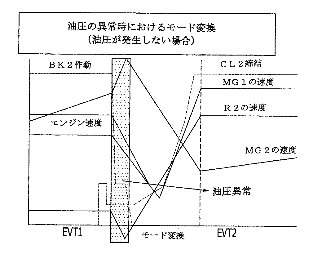
図3は、第1モードと第2モードでハイブリッド車両の各部分の速度を示す図であり、図4は、正常状態での変速の場合、モード変換時の各部分の速度変化を示す図である。
この過程において、第2リングギヤ(R2)が第2ブレーキ(BK2)によって停止された後、第2クラッチ(CL2)が締結しながらエンジン(ENGINE)と連結してエンジン速度と同期化する。
FIG. 3 is a diagram showing the speed of each part of the hybrid vehicle in the first mode and the second mode, and FIG. 4 is a diagram showing the speed change of each part at the time of mode conversion in the case of shifting in a normal state. is there.
In this process, after the second ring gear (R2) is stopped by the second brake (BK2), the second clutch (CL2) is engaged with the engine (ENGINE) and is synchronized with the engine speed.
また、第2モータジェネレータ(MG2)の速度は、図4に示すように、第1モード(EVT1)から第2モード(EVT2)に変換しながらゆっくりと減少しなければならない。しかし、異物などによって電気可変トランスミッションの油圧に異常がある場合には、図4に示す正常状態において、第1モード(EVT1)から第2モード(EVT2)に変換する場合とは異なる速度変化を示すようになり、これを比較すれば異常の発生可否を把握できるようになる。 Further, as shown in FIG. 4, the speed of the second motor generator (MG2) must be slowly decreased while converting from the first mode (EVT1) to the second mode (EVT2). However, when there is an abnormality in the hydraulic pressure of the electric variable transmission due to foreign matter or the like, the normal state shown in FIG. 4 shows a speed change different from the case of converting from the first mode (EVT1) to the second mode (EVT2). By comparing these, it becomes possible to grasp whether or not an abnormality has occurred.
従って、本発明では、第1モード(EVT1)から第2モード(EVT2)に変換する場合、図1に示すように、第2クラッチ(CL2)に油圧が発生しないか否か、および油圧が予め設定された値を超過して発生するか否かを判断することによって異常の発生可否を判断する(S20)。 Therefore, in the present invention, when converting from the first mode (EVT1) to the second mode (EVT2), as shown in FIG. 1, whether or not the hydraulic pressure is not generated in the second clutch (CL2), and the hydraulic pressure is set in advance. It is determined whether or not an abnormality has occurred by determining whether or not the value exceeds the set value (S20).
異物の流入による油圧異常は、油圧が発生しない場合(S21)と油圧が予め設定された値を超過して過度に大きく発生する場合(S22)とに分けてもよい。 The oil pressure abnormality due to the inflow of foreign matter may be divided into a case where no oil pressure is generated (S21) and a case where the oil pressure exceeds a preset value and is excessively large (S22).
正常状態である場合には、第1モード(EVT1)から第2モード(EVT2)に転換する場合、第2ブレーキ(BK2)の圧力が解除され、第2クラッチ(CL2)の締結によって第2リングギヤ(R2)がエンジンの速度と同期化しなければならない。 In the normal state, when switching from the first mode (EVT1) to the second mode (EVT2), the pressure of the second brake (BK2) is released and the second ring gear is engaged by engaging the second clutch (CL2). (R2) must be synchronized with the engine speed.
しかし、油圧が発生しない場合(S21)には、第1モード(EVT1)から第2モード(EVT2)に転換する場合にも、第2クラッチ(CL2)に油圧が発生せずに締結圧力がないため、図5に示すように遊星ギヤのレバーが全体的に反対に回転するようになり、第2モータジェネレータ(MG2)の速度は急激に上昇し、第2リングギヤ(R2)の速度は逆回転によって負(−)の値を有するようになる。 However, when no hydraulic pressure is generated (S21), even when switching from the first mode (EVT1) to the second mode (EVT2), no hydraulic pressure is generated in the second clutch (CL2) and there is no engagement pressure. Therefore, as shown in FIG. 5, the planetary gear lever rotates as a whole in the opposite direction, the speed of the second motor generator (MG2) rapidly increases, and the speed of the second ring gear (R2) reversely rotates. Has a negative (−) value.
この後、突然に第2クラッチ(CL2)に油圧が発生することにより、図5に示すように第2モータジェネレータ(MG2)の速度が減少し、第2リングギヤ(R2)とエンジンの速度が同期化すれば車両に変速衝撃が発生するようになる。 Thereafter, the hydraulic pressure is suddenly generated in the second clutch (CL2), so that the speed of the second motor generator (MG2) decreases as shown in FIG. 5, and the speed of the second ring gear (R2) and the engine are synchronized. If this happens, a shift impact will occur in the vehicle.
油圧が発生しない場合(S21)を数式で表現すると、下記数式(1)のように表すことができる。
ハイブリッド車両のマルチモード変速機の場合、一般的なガソリン車両とは異なり、第2モータジェネレータ(MG2)の速度を計測しているため、数式(1)を利用して第2リングギヤ(R2)の速度が計算される。
When the hydraulic pressure is not generated (S21), it can be expressed as the following mathematical expression (1).
In the case of a multi-mode transmission of a hybrid vehicle, unlike a general gasoline vehicle, the speed of the second motor generator (MG2) is measured. Therefore, the second ring gear (R2) is calculated using Equation (1). The speed is calculated.
数式(1)において、ωR2は図2に示す第2リングギヤ(R2)の速度、ωoutは出力要素(Output)の速度、ωMG2は第2モータジェネレータ(MG2)の速度であり、ZR2は第2リングギヤの半径または歯数、ZS2は第2サンギヤの半径または歯数である。 In Equation (1), ω R2 is the speed of the second ring gear (R2) shown in FIG. 2, ω out is the speed of the output element (Output), ω MG2 is the speed of the second motor generator (MG2), and Z R2 Is the radius or number of teeth of the second ring gear, and Z S2 is the radius or number of teeth of the second sun gear.
数式(1)によれば、第2リングギヤ(R2)の速度(ωR2)が負の値であり、第2モータジェネレータ(MG2)の速度(ωMG2)の傾きが正の値である場合に、第2クラッチ(CL2)に油圧が発生しないものと判断できる。 According to Equation (1), the speed of the second ring gear (R2) (omega R2) is a negative value, when the inclination of the speed of the second motor generator (MG2) (omega MG2) is a positive value It can be determined that no hydraulic pressure is generated in the second clutch (CL2).
一方、第2クラッチ(CL2)に油圧が予め設定された値を超過して過度に発生する場合(S22)には、第1モード(EVT1)から第2モード(EVT2)に変換するとき、図3の正常状態の場合よりも第2モータジェネレータ(MG2)の速度が急激に減少し、第2リングギヤ(R2)の速度は急激に上昇し、エンジンの速度と同期化して変速衝撃が発生するようになる。 On the other hand, when the hydraulic pressure in the second clutch (CL2) exceeds a preset value and excessively occurs (S22), when changing from the first mode (EVT1) to the second mode (EVT2), FIG. 3 so that the speed of the second motor generator (MG2) decreases more rapidly than in the normal state of FIG. 3, the speed of the second ring gear (R2) increases rapidly, and a speed change impact is generated in synchronization with the engine speed. become.
油圧が予め設定された値を超過して過度に発生する場合(S22)を数式で表現すれば、数式(2)のように表すことができる。 If the hydraulic pressure exceeds a preset value and excessively occurs (S22), it can be expressed as Equation (2).
数式(2)において、ωR2は図2に示す第2リングギヤ(R2)の速度、ωMG2は第2モータジェネレータ(MG2)の速度であり、Acriteria−maxは予め設定された正常基準範囲の最大値、Bcriteria−minは予め設定された正常基準範囲の最小値である。
Acriteria−max値とBcriteria−min値は、試験によって決定してもよい。
In Formula (2), ω R2 is the speed of the second ring gear (R2) shown in FIG. 2, ω MG2 is the speed of the second motor generator (MG2), and A criteria-max is a preset normal reference range. The maximum value, B criteria -min is the minimum value of the normal reference range set in advance.
The A criteria-max value and the B criteria-min value may be determined by testing.
数式(2)によれば、第2リングギヤの速度(ωR2)の傾きが正常基準範囲の最大値(Acriteria−max)よりも大きく、第2モータジェネレータの速度(ωMG2)の傾きが正常基準範囲の最小値(Bcriteria−min)よりも小さい場合、油圧が予め設定された値を超過して過度に発生する場合として判断する。 According to Equation (2), the inclination of the speed (ω R2 ) of the second ring gear is larger than the maximum value (A criteria−max ) of the normal reference range, and the inclination of the speed (ω MG2 ) of the second motor generator is normal. When it is smaller than the minimum value (B criteria-min ) of the reference range, it is determined that the oil pressure is excessively generated exceeding a preset value.
このように油圧が発生しない場合(S21)または油圧が予め設定された値を超過して過度に発生する場合(S22)と判断されれば、車両の制御部で車両異常として判断し(S30)、運転手に異常信号を出し、車両停止後に変速レバーをN段に誘導し(S31)、N段かどうかを確認する(S32)。 If it is determined that the hydraulic pressure does not occur (S21) or the hydraulic pressure exceeds the preset value and excessively occurs (S22), the vehicle control unit determines that the vehicle is abnormal (S30). Then, an abnormal signal is output to the driver, and after the vehicle stops, the shift lever is guided to the N stage (S31), and it is confirmed whether or not it is the N stage (S32).
車両異常と判断されて車両のN段となる場合、異物を除去するために直接制御ソレノイドバルブをデューティ(Duty)0〜100%まで数回に渡って強制駆動する(S40)。直接制御ソレノイドバルブの強制駆動の回数と時間間隔は、原理試験によって決定することができる。 When it is determined that the vehicle is abnormal and the vehicle is in the N stage, the direct control solenoid valve is forcibly driven several times from 0 to 100% in order to remove foreign matter (S40). The number and time interval of the forced drive of the direct control solenoid valve can be determined by principle tests.
車両の制御部は、強制駆動後に車両が走行する場合、車両の異常状態の有無を再判断する(S50)。強制駆動後にも異物が完全に除去されていない場合があるため、車両の制御部では運転手に車両の変速レバーをD段で走行するように誘導し、整備所工場に案内する(S51)。 When the vehicle travels after forced driving, the vehicle control unit re-determines whether the vehicle is in an abnormal state (S50). Since the foreign matter may not be completely removed even after forced driving, the vehicle control unit guides the driver to travel the shift lever of the vehicle in the D stage and guides it to the maintenance shop (S51).
この案内過程において、車両の制御部は、油圧が発生しないか否かまたは油圧が予め設定された値を超過して過度に発生するか否かを再び判断する(S52)。 In this guidance process, the control unit of the vehicle determines again whether or not the hydraulic pressure is generated or whether or not the hydraulic pressure is excessively generated exceeding a preset value (S52).
この再判断でも異常が発生すると判断される場合、車両の制御部でモードを第1モード(EVT1)に固定し、運転手に変速レバーをD段にして整備工場に移動するように誘導する(S60)。 If it is determined that an abnormality occurs even in this re-determination, the mode is fixed to the first mode (EVT1) by the control unit of the vehicle, and the driver is guided to move to the maintenance shop with the shift lever set to the D stage ( S60).
以上、本発明によるハイブリッド車両用変速機の油圧異常診断および制御方法を説明したが、本発明は上記の実施形態に限定されるものではなく、本発明の実施形態から当該発明が属する技術分野において通常の知識を有する者によって容易に変更され、均等であると認められる範囲のすべての変更を含むものである。 The hydraulic abnormality diagnosis and control method for a hybrid vehicle transmission according to the present invention has been described above. However, the present invention is not limited to the above embodiment, and the technical field to which the present invention belongs from the embodiment of the present invention. It is easily changed by a person having ordinary knowledge, and includes all changes within a range that is recognized as equivalent.
1:第1差動ギヤ装置
3:第2差動ギヤ装置
S1:サンギヤ
C1:第1キャリア
R1:第1リングギヤ
S2:第2サンギヤ
C2:第2キャリア
R2:第2リングギヤ
MG1:第1モータジェネレータ
MG2:第2モータジェネレータ
BK1:第1ブレーキ
BK2:第2ブレーキ
CL1:第1クラッチ
CL2:第2クラッチ
Output:出力要素
1: first differential gear device 3: second differential gear device S1: sun gear C1: first carrier R1: first ring gear S2: second sun gear C2: second carrier R2: second ring gear MG1: first motor generator MG2: second motor generator BK1: first brake BK2: second brake CL1: first clutch CL2: second clutch Output: output element
Claims (5)
前記第1差動ギヤ装置(1)及び前記第2差動ギヤ装置(3)は、それぞれ遊星ギヤ装置からなり、前記第1差動ギヤ装置(1)は、第1サンギヤ(S1)、第1キャリア(C1)、および第1リングギヤ(R1)からなり、前記第2差動ギヤ装置(3)は、第2サンギヤ(S2)、第2キャリア(C2)、および第2リングギヤ(R2)からなり、
前記第1サンギヤ(S1)は、前記第2サンギヤ(S2)に常に連結し、前記第1キャリア(C1)は第2クラッチ(CL2)を介して前記第2リングギヤ(R2)に連結するとともに前記エンジン(ENGINE)と直接に連結し、
前記第1リングギヤ(R1)は、前記第1モータジェネレータ(MG1)に常に連結し、前記第2サンギヤ(S2)は前記第2モータジェネレータ(MG2)に常に連結し、前記第2キャリア(C2)は、前記出力要素(Output)に常に連結し、
第2ブレーキ(BK2)が、前記第2リングギヤ(R2)の回転を拘束できるように設置され、
第1クラッチ(CL1)が、前記第1キャリア(C1)と前記第1リングギヤ(R1)の間を選択的に連結できるように設置され、第1ブレーキ(BK1)が、前記第1リングギヤ(R1)の回転を拘束できるように設置されたハイブリッド車両の電気可変トランスミッションにおいて、
前記第2ブレーキ(BK2)を解除し、前記第2クラッチ(CL2)を締結して第1モードから第2モードに変換するマルチモード電気可変トランスミッションからなるハイブリッド車両用変速機の油圧異常診断および制御方法であって、
前記第1モードから前記第2モードに変換するか否かを判断する段階と、
前記第2モードに変換する場合、これによって締結したクラッチに油圧が発生するか否かおよび油圧が予め設定された値を超過して発生するか否かを判断する段階と、
前記判断において、前記クラッチに油圧が発生しなかったりまたは油圧が前記予め設定された値を超過して発生したりする場合に車両異常として判断する段階と、
を含んで構成され、
前記第2モードの第2リングギヤの速度(ωR2)が負の値を有し、前記第2モードの前記第2モータジェネレータの速度(ωMG2)の時間による変化率(傾き)が正の値を有する場合、油圧が発生しないものと判断することを特徴とするハイブリッド車両用変速機の油圧異常診断および制御方法。 An engine (ENGINE), a first motor generator (MG1), a second motor generator (MG2), a first differential gear device (1), a second differential gear device (3), and an output element (Output) ) And
The first differential gear device (1) and the second differential gear device (3) are each composed of a planetary gear device, and the first differential gear device (1) is a first sun gear (S1), a second gear device. The second differential gear device (3) includes a second sun gear (S2), a second carrier (C2), and a second ring gear (R2). The first differential gear device (3) includes one carrier (C1) and a first ring gear (R1). Become
The first sun gear (S1) is always connected to the second sun gear (S2), and the first carrier (C1) is connected to the second ring gear (R2) via a second clutch (CL2) and Connect directly with the engine (ENGINE)
The first ring gear (R1) is always connected to the first motor generator (MG1), the second sun gear (S2) is always connected to the second motor generator (MG2), and the second carrier (C2). Is always connected to the output element (Output),
A second brake (BK2) is installed so as to restrain the rotation of the second ring gear (R2);
A first clutch (CL1) is installed to selectively connect the first carrier (C1) and the first ring gear (R1), and a first brake (BK1) is connected to the first ring gear (R1). ) In an electric variable transmission of a hybrid vehicle installed so as to restrain rotation of
Hydraulic pressure abnormality diagnosis and control of a hybrid vehicle transmission including a multi-mode electric variable transmission that releases the second brake (BK2), engages the second clutch (CL2), and converts the first mode to the second mode. A method,
Determining whether to convert from the first mode to the second mode;
When converting to the second mode, determining whether or not the hydraulic pressure is generated in the engaged clutch and whether or not the hydraulic pressure exceeds a preset value;
In the determination, when the hydraulic pressure is not generated in the clutch or when the hydraulic pressure exceeds the preset value, the vehicle is determined to be abnormal.
Comprising
The speed (ω R2 ) of the second ring gear in the second mode has a negative value, and the rate of change (slope) with time of the speed (ω MG2 ) of the second motor generator in the second mode is a positive value. A hydraulic pressure abnormality diagnosis and control method for a hybrid vehicle transmission, wherein it is determined that no hydraulic pressure is generated.
5. The hybrid vehicle transmission according to claim 4, further comprising a step of fixing the mode of the electric variable transmission to the first mode when it is determined in the re-determination that the vehicle is abnormal. Hydraulic abnormality diagnosis and control method.
Applications Claiming Priority (2)
| Application Number | Priority Date | Filing Date | Title |
|---|---|---|---|
| KR10-2011-0132264 | 2011-12-09 | ||
| KR1020110132264A KR101416353B1 (en) | 2011-12-09 | 2011-12-09 | Check and control method of hydraulic failure in automatic transmission of hybrid vehicle |
Publications (2)
| Publication Number | Publication Date |
|---|---|
| JP2013121819A JP2013121819A (en) | 2013-06-20 |
| JP6077762B2 true JP6077762B2 (en) | 2017-02-08 |
Family
ID=48464763
Family Applications (1)
| Application Number | Title | Priority Date | Filing Date |
|---|---|---|---|
| JP2012133247A Expired - Fee Related JP6077762B2 (en) | 2011-12-09 | 2012-06-12 | Hydraulic abnormality diagnosis and control method for hybrid vehicle transmission |
Country Status (5)
| Country | Link |
|---|---|
| US (1) | US8900096B2 (en) |
| JP (1) | JP6077762B2 (en) |
| KR (1) | KR101416353B1 (en) |
| CN (1) | CN103161938B (en) |
| DE (1) | DE102012106706A1 (en) |
Families Citing this family (2)
| Publication number | Priority date | Publication date | Assignee | Title |
|---|---|---|---|---|
| KR101509943B1 (en) * | 2013-10-22 | 2015-04-07 | 현대자동차주식회사 | Fail-Safe Control Method for a clutch actuator of the Engine and the apparatus thereof |
| KR101846907B1 (en) | 2016-08-22 | 2018-05-28 | 현대자동차 주식회사 | Apparatus and method for determining faulty of engine clutch |
Family Cites Families (20)
| Publication number | Priority date | Publication date | Assignee | Title |
|---|---|---|---|---|
| JPH094710A (en) * | 1995-06-07 | 1997-01-07 | Caterpillar Inc | Mode control system at time of trouble for split torque transmission |
| KR20020041921A (en) | 2000-11-29 | 2002-06-05 | 이계안 | Apparatus for alert to disparate matter in oil in automatic transmission of automobile and method of the same |
| JP3981317B2 (en) | 2002-10-04 | 2007-09-26 | ジヤトコ株式会社 | Hydraulic pressure drop detecting device for vehicle transmission |
| JP3992025B2 (en) * | 2004-07-02 | 2007-10-17 | 日産自動車株式会社 | Fail detection device for hybrid system |
| JP4784196B2 (en) * | 2005-08-05 | 2011-10-05 | トヨタ自動車株式会社 | Hydraulic control device |
| JP4337812B2 (en) * | 2005-12-21 | 2009-09-30 | トヨタ自動車株式会社 | Failure determination device for hydraulic control circuit |
| JP4722710B2 (en) * | 2006-01-11 | 2011-07-13 | トヨタ自動車株式会社 | Hydraulic control device for transmission |
| JP2007309429A (en) * | 2006-05-18 | 2007-11-29 | Fujitsu Ten Ltd | Failure detecting method of line oil pressure control part |
| JP4867594B2 (en) * | 2006-11-10 | 2012-02-01 | 日産自動車株式会社 | Vehicle control device |
| US7648440B2 (en) | 2007-01-24 | 2010-01-19 | Gm Global Technology Operations, Inc. | Method and apparatus to control operation of an electro-mechanical transmission |
| US7670254B2 (en) * | 2007-01-24 | 2010-03-02 | Gm Global Technology Operations, Inc. | Method and apparatus to monitor devices of a hydraulic circuit of an electro-mechanical transmission |
| US7867135B2 (en) * | 2007-09-26 | 2011-01-11 | GM Global Technology Operations LLC | Electro-mechanical transmission control system |
| KR20090047706A (en) | 2007-11-08 | 2009-05-13 | 현대자동차주식회사 | Variable force solenoid valve for auto-transmission of vehicle |
| JP4901716B2 (en) * | 2007-12-27 | 2012-03-21 | トヨタ自動車株式会社 | Vehicle linear solenoid valve abnormality determination device |
| JP2010036867A (en) * | 2008-08-08 | 2010-02-18 | Toyota Motor Corp | Device for controlling power transmission device for vehicle |
| JP4927053B2 (en) | 2008-09-25 | 2012-05-09 | 本田技研工業株式会社 | Oil pressure abnormality detection device for continuously variable transmission |
| US20100087999A1 (en) * | 2008-10-03 | 2010-04-08 | Gm Global Technology Operations, Inc. | Apparatus and Method for Detecting End-of-Fill at Clutch in Automatic Transmission |
| KR101063494B1 (en) | 2009-03-23 | 2011-09-07 | 기아자동차주식회사 | Solenoid Valve Foreign Material Removal Device and Method |
| KR101113576B1 (en) * | 2009-11-09 | 2012-02-22 | 현대자동차주식회사 | Transmission for Hybrid Vehicle |
| EP2393292A1 (en) | 2010-06-01 | 2011-12-07 | Nagravision S.A. | A method and apparatus for decrypting encrypted content |
-
2011
- 2011-12-09 KR KR1020110132264A patent/KR101416353B1/en active IP Right Grant
-
2012
- 2012-06-12 JP JP2012133247A patent/JP6077762B2/en not_active Expired - Fee Related
- 2012-07-12 US US13/547,864 patent/US8900096B2/en not_active Expired - Fee Related
- 2012-07-24 DE DE102012106706A patent/DE102012106706A1/en not_active Withdrawn
- 2012-07-25 CN CN201210260401.1A patent/CN103161938B/en not_active Expired - Fee Related
Also Published As
| Publication number | Publication date |
|---|---|
| KR20130065417A (en) | 2013-06-19 |
| JP2013121819A (en) | 2013-06-20 |
| KR101416353B1 (en) | 2014-07-16 |
| CN103161938B (en) | 2016-09-21 |
| US8900096B2 (en) | 2014-12-02 |
| DE102012106706A1 (en) | 2013-06-13 |
| US20130150209A1 (en) | 2013-06-13 |
| CN103161938A (en) | 2013-06-19 |
Similar Documents
| Publication | Publication Date | Title |
|---|---|---|
| CN100473880C (en) | Vehicle drive control apparatus and method | |
| CN101643034B (en) | Vehicle deceleration rate control method and apparatus | |
| CN104728364B (en) | power transmission device for hybrid vehicle | |
| CN103085644B (en) | Wide-node Drive System | |
| US20140303822A1 (en) | Control device for hybrid vehicle | |
| CN103827551B (en) | The gear change control device of automatic transmission and method | |
| WO2013129053A1 (en) | Vehicle shift control device | |
| CN105121239B (en) | The control device of hybrid vehicle | |
| WO2012172828A1 (en) | Shift control device for automatic transmission | |
| KR20160084036A (en) | Method for learning kisspoint of engine clutch in hybrid vehicle | |
| JP2015051686A (en) | Drive control device of vehicle | |
| JP6077762B2 (en) | Hydraulic abnormality diagnosis and control method for hybrid vehicle transmission | |
| JP4570859B2 (en) | Relay welding detection device and relay welding detection method | |
| JP2003294130A (en) | Control device for hybrid vehicle | |
| JP2011033516A (en) | Testing device for vehicle having multiple power sources | |
| KR101326822B1 (en) | System for fail safety control of hybrid vehicle and method thereof | |
| JP2016047676A (en) | Hybrid-vehicular control apparatus | |
| JP6102182B2 (en) | Control device for hybrid vehicle | |
| KR101583990B1 (en) | Plug-in Hybrid Electric Vehicle and Driving Control Method thereof | |
| KR102545108B1 (en) | Hybrid vehicle and method of calibrating engine axle position for the same | |
| KR20110116584A (en) | Method for learning transmission of hybrid vehicle | |
| KR101367285B1 (en) | method for ensuring the reliability of speed sensors for hybrid vehicle | |
| KR101806640B1 (en) | Method for controlling driving of hybrid vehicles | |
| JP5074758B2 (en) | VEHICLE CONTROL DEVICE, CONTROL METHOD, PROGRAM FOR IMPLEMENTING THE METHOD, RECORDING MEDIUM CONTAINING THE PROGRAM, AND VEHICLE DRIVE DEVICE | |
| KR102187453B1 (en) | Apparatus and method for control of engine clutch |
Legal Events
| Date | Code | Title | Description |
|---|---|---|---|
| A621 | Written request for application examination |
Free format text: JAPANESE INTERMEDIATE CODE: A621 Effective date: 20150521 |
|
| A131 | Notification of reasons for refusal |
Free format text: JAPANESE INTERMEDIATE CODE: A131 Effective date: 20160216 |
|
| A977 | Report on retrieval |
Free format text: JAPANESE INTERMEDIATE CODE: A971007 Effective date: 20160218 |
|
| A521 | Request for written amendment filed |
Free format text: JAPANESE INTERMEDIATE CODE: A523 Effective date: 20160513 |
|
| A131 | Notification of reasons for refusal |
Free format text: JAPANESE INTERMEDIATE CODE: A131 Effective date: 20160719 |
|
| A521 | Request for written amendment filed |
Free format text: JAPANESE INTERMEDIATE CODE: A523 Effective date: 20160831 |
|
| TRDD | Decision of grant or rejection written | ||
| A01 | Written decision to grant a patent or to grant a registration (utility model) |
Free format text: JAPANESE INTERMEDIATE CODE: A01 Effective date: 20161220 |
|
| A61 | First payment of annual fees (during grant procedure) |
Free format text: JAPANESE INTERMEDIATE CODE: A61 Effective date: 20170113 |
|
| R150 | Certificate of patent or registration of utility model |
Ref document number: 6077762 Country of ref document: JP Free format text: JAPANESE INTERMEDIATE CODE: R150 |
|
| R250 | Receipt of annual fees |
Free format text: JAPANESE INTERMEDIATE CODE: R250 |
|
| R250 | Receipt of annual fees |
Free format text: JAPANESE INTERMEDIATE CODE: R250 |
|
| LAPS | Cancellation because of no payment of annual fees |