JP2010065795A - Method and device for diagnosis of clutch failure of industrial vehicle - Google Patents
Method and device for diagnosis of clutch failure of industrial vehicle Download PDFInfo
- Publication number
- JP2010065795A JP2010065795A JP2008234289A JP2008234289A JP2010065795A JP 2010065795 A JP2010065795 A JP 2010065795A JP 2008234289 A JP2008234289 A JP 2008234289A JP 2008234289 A JP2008234289 A JP 2008234289A JP 2010065795 A JP2010065795 A JP 2010065795A
- Authority
- JP
- Japan
- Prior art keywords
- clutch
- life
- absorption energy
- failure diagnosis
- equation
- Prior art date
- Legal status (The legal status is an assumption and is not a legal conclusion. Google has not performed a legal analysis and makes no representation as to the accuracy of the status listed.)
- Granted
Links
Images

Abstract
Description
本発明は産業車両のクラッチ故障診断方法及び装置に関する。 The present invention relates to a clutch failure diagnosis method and apparatus for industrial vehicles.
フォークリフトなどの産業車両の故障診断装置では、従来、リアルタイムで前記産業車両の各部材の状態を検出する各センサからの検出信号を監視し、この検出信号の値としきい値とを比較することによって、前記各部材の正常/異常の判断を行っている。 Conventionally, a failure diagnosis apparatus for industrial vehicles such as forklifts monitors a detection signal from each sensor that detects the state of each member of the industrial vehicle in real time, and compares the value of the detection signal with a threshold value. The normality / abnormality of each member is determined.
なお、関連する先行技術文献としては次のものがある。
特にフォークリフト等の産業車両では、その運転状況(運転の頻度や負荷の大きさなどの状況)がユーザの作業内容などに応じて実に様々である。従って、フォークリフトに備えたクラッチなどの各部材の故障時期(寿命)も、前記運転状況に応じて実に様々であるため、前記部材のメンテナンス時期を一律に設定することはできない。このため、例えば事前に交換部品の準備など行って効率的にメンテナンスを行おうとする場合、前記運転状況に応じた前記部材の寿命を求めることによって、前記部材のメンテナンス時期を推定する必要がある。 In particular, in an industrial vehicle such as a forklift, the driving situation (situation such as the frequency of driving and the magnitude of the load) varies depending on the work contents of the user. Accordingly, the failure time (life) of each member such as a clutch provided in the forklift varies depending on the operation status, and therefore the maintenance time of the member cannot be set uniformly. For this reason, when it is going to perform maintenance efficiently, for example by preparing replacement parts in advance, it is necessary to estimate the maintenance time of the member by obtaining the lifetime of the member according to the operation status.
しかしながら、上記の如く従来の故障診断装置では、リアルタイムで各センサからの検出信号を監視して正常/異常の判断を行っているだけであるため、クラッチなどの部材がどれくらいの稼働時間で故障するのか(どれくらい寿命があるのか)を判断することができず、前記部材のメンテナンス時期を推定することができなかった。 However, as described above, the conventional failure diagnosis device only monitors the detection signal from each sensor in real time to determine whether it is normal or abnormal. It was not possible to determine (how long the service life is), and the maintenance time of the member could not be estimated.
従って本発明は上記の事情に鑑み、運転状況に応じたクラッチ寿命やクラッチ残存寿命を求めることができるフォークリフト等の産業車両のクラッチ故障診断方法及び装置を提供することを課題とする。 Therefore, in view of the above circumstances, an object of the present invention is to provide a clutch failure diagnosis method and apparatus for industrial vehicles such as forklifts that can determine the clutch life and the remaining clutch life according to the driving situation.
上記課題を解決する第1発明の産業車両のクラッチ故障診断方法は、産業車両に装備されたクラッチの故障診断方法であって、
検出したクラッチ前後の回転速度差ΔVと、検出したクラッチ油圧Pと、クラッチ板の摩擦係数μとに基づいて、次の[数9]式から、クラッチ吸収エネルギqを計算し、

Based on the detected rotational speed difference ΔV before and after the clutch, the detected clutch oil pressure P, and the friction coefficient μ of the clutch plate, the clutch absorption energy q is calculated from the following [Equation 9],
また、第2発明の産業車両のクラッチ故障診断方法は、第1発明の産業車両のクラッチ故障診断方法において、
前記クラッチ寿命LHと、検出した車両稼動時間tNとに基づいて、次の[数12]式から、クラッチ残存寿命LRを計算すること、
Based on the clutch life L H and the detected vehicle operating time t N , calculating the clutch remaining life L R from the following [Equation 12],
また、第3発明の産業車両のクラッチ故障診断装置は、産業車両に装備されたクラッチの故障診断装置であって、
クラッチ前後の回転速度差ΔVを検出するクラッチ前後回転速度差検出手段と、
クラッチ油圧Pを検出するクラッチ油圧検出手段と、
前記クラッチ前後回転速度差検出手段で検出したクラッチ前後回転速度差ΔVと、前記クラッチ油圧検出手段で検出したクラッチ油圧Pと、クラッチ板の摩擦係数μとに基づいて、次の[数13]式から、クラッチ吸収エネルギqを計算するクラッチ吸収エネルギ計算手段と、
A clutch front-rear rotational speed difference detecting means for detecting a rotational speed difference ΔV before and after the clutch;
Clutch oil pressure detecting means for detecting the clutch oil pressure P;
Based on the clutch longitudinal rotational speed difference ΔV detected by the clutch longitudinal rotational speed difference detecting means, the clutch hydraulic pressure P detected by the clutch hydraulic pressure detecting means, and the friction coefficient μ of the clutch plate, the following equation (13) A clutch absorption energy calculating means for calculating the clutch absorption energy q from
また、第4発明の産業車両のクラッチ故障診断装置は、第3発明の産業車両のクラッチ故障診断装置において、
産業車両の稼働時間tNを検出する車両稼働時間検出手段と、
前記クラッチ寿命計算手段で計算したクラッチ寿命LHと、前記車両稼働時間検出手段で検出した車両稼動時間tNとに基づいて、次の[数16]式から、クラッチ残存寿命LRを計算するクラッチ残存寿命計算手段と、
![]()
Vehicle operating time detecting means for detecting the operating time t N of the industrial vehicle;
Wherein the clutch lifetime L H calculated by the clutch life calculation means, wherein based on the vehicle operation time detected by the vehicle operating time detecting means t N, the following equation [16] equation to calculate the clutch remaining lifetime L R Clutch remaining life calculating means,
![]()
第1発明の産業車両のクラッチ故障診断方法によれば、産業車両に装備されたクラッチの故障診断方法であって、検出したクラッチ前後の回転速度差ΔVと検出したクラッチ油圧Pとクラッチ板の摩擦係数μとに基づいて[数9]式からクラッチ吸収エネルギqを計算し、このクラッチ吸収エネルギqを[数10]式のように積分して単位時間t当たりのクラッチ吸収エネルギ積算値Qを計算し、このクラッチ吸収エネルギ積算値Qと寿命限界のクラッチ吸収エネルギ積算値Qlimitと前記単位時間tとに基づいて[数11]式からクラッチ寿命LHを計算することを特徴としているため、産業車両の運転状況に応じたクラッチ寿命LHを求めることができる。 According to the clutch failure diagnosis method for an industrial vehicle of the first aspect of the present invention, there is provided a failure diagnosis method for a clutch mounted on an industrial vehicle, wherein the detected rotational speed difference ΔV before and after the clutch and the detected clutch hydraulic pressure P and the friction between the clutch plates. Based on the coefficient μ, the clutch absorption energy q is calculated from the equation [9], and the clutch absorption energy q is integrated as shown in the equation [10] to calculate the clutch absorption energy integrated value Q per unit time t. The clutch life L H is calculated from the equation (11) based on the clutch absorption energy integrated value Q, the life limit clutch absorption energy integrated value Q limit and the unit time t. it can be determined clutch life L H in accordance with the operating conditions of the vehicle.
第2発明の産業車両のクラッチ故障診断方法によれば、第1発明の産業車両のクラッチ故障診断方法において、前記クラッチ寿命LHと検出した車両稼動時間tNとに基づいて[数12]式からクラッチ残存寿命LRを計算することを特徴としているため、産業車両の運転状況に応じたクラッチ残存寿命LRを求めることができる。従って、このクラッチ残存寿命LRに基づいて、産業車両の運転状況に応じたクラッチのメンテナンス時期を推定することもできる。 According to the industrial vehicle clutch failure diagnosis method of the second aspect of the invention, in the industrial vehicle clutch failure diagnosis method of the first aspect of the invention, the equation [12] is used based on the clutch life L H and the detected vehicle operating time t N. because it is characterized in that to calculate the clutch remaining lifetime L R from, it is possible to determine the clutch remaining lifetime L R according to the operating conditions of the industrial vehicle. Therefore, based on the remaining clutch life LR , it is possible to estimate the clutch maintenance time according to the operating condition of the industrial vehicle.
第3発明の産業車両のクラッチ故障診断装置によれば、産業車両に装備されたクラッチの故障診断装置であって、クラッチ前後の回転速度差ΔVを検出するクラッチ前後回転速度差検出手段と、クラッチ油圧Pを検出するクラッチ油圧検出手段と、前記クラッチ前後回転速度差検出手段で検出したクラッチ前後回転速度差ΔVと前記クラッチ油圧検出手段で検出したクラッチ油圧Pとクラッチ板の摩擦係数μとに基づいて[数13]式からクラッチ吸収エネルギqを計算するクラッチ吸収エネルギ計算手段と、前記クラッチ吸収エネルギ計算手段で計算したクラッチ吸収エネルギqを[数14]式のように積分して単位時間t当たりのクラッチ吸収エネルギ積算値Qを計算するクラッチ吸収エネルギ積算手段と、前記クラッチ吸収エネルギ積算手段で計算したクラッチ吸収エネルギ積算値Qと寿命限界のクラッチ吸収エネルギ積算値Qlimitと前記単位時間tとに基づいて[数15]式からクラッチ寿命LHを計算するクラッチ寿命計算手段とを備えたことを特徴としているため、上記第1発明と同様、産業車両の運転状況に応じたクラッチ寿命LHを求めることができる。 According to the industrial vehicle clutch failure diagnosis device of the third aspect of the present invention, there is provided a clutch failure diagnosis device equipped in an industrial vehicle, the clutch front-rear rotational speed difference detecting means for detecting the rotational speed difference ΔV before and after the clutch, and the clutch Based on the clutch oil pressure detecting means for detecting the oil pressure P, the clutch front / rear rotation speed difference ΔV detected by the clutch front / rear rotation speed difference detecting means, and the clutch oil pressure P detected by the clutch oil pressure detecting means and the friction coefficient μ of the clutch plate. The clutch absorption energy calculation means for calculating the clutch absorption energy q from the equation [13] and the clutch absorption energy q calculated by the clutch absorption energy calculation means are integrated as shown in the equation [14] to obtain per unit time t. Clutch absorption energy integration means for calculating the clutch absorption energy integration value Q of the clutch, and the clutch absorption energy integration A clutch life calculation means for calculating a clutch life L H from the number 15 expression based on the clutch absorbed energy accumulated value of the clutch absorbed energy integration value Q and lifetime limit calculated in step Q limit and the unit time t since it is characterized in that the, as with the first invention, it is possible to obtain the clutch lifetime L H in accordance with the operating conditions of the industrial vehicle.
第4発明の産業車両のクラッチ故障診断装置によれば、第3発明の産業車両のクラッチ故障診断装置において、産業車両の稼働時間tNを検出する車両稼働時間検出手段と、前記クラッチ寿命計算手段で計算したクラッチ寿命LHと前記車両稼働時間検出手段で検出した車両稼動時間tNとに基づいて[数16]式からクラッチ残存寿命LRを計算するクラッチ残存寿命計算手段とを備えたことを特徴としているため、上記第2発明と同様、産業車両の運転状況に応じたクラッチ残存寿命LRを求めることができる。従って、このクラッチ残存寿命LRに基づいて、産業車両の運転状況に応じたクラッチのメンテナンス時期を推定することもできる。 According to the industrial vehicle clutch failure diagnosis device of the fourth invention, in the industrial vehicle clutch failure diagnosis device of the third invention, the vehicle operation time detection means for detecting the operation time t N of the industrial vehicle, and the clutch life calculation means. And a clutch remaining life calculating means for calculating the clutch remaining life L R from the equation [16] based on the clutch life L H calculated in step 1 and the vehicle operating time t N detected by the vehicle operating time detecting means. due to the characterized, as in the second invention, it is possible to obtain the clutch remaining lifetime L R according to the operating conditions of the industrial vehicle. Therefore, based on the remaining clutch life LR , it is possible to estimate the clutch maintenance time according to the operating condition of the industrial vehicle.
以下、本発明の実施の形態例を図面に基づいて詳細に説明する。 Embodiments of the present invention will be described below in detail with reference to the drawings.
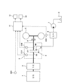
図1は本発明の実施の形態例に係るフォークリフトの動力伝達系とクラッチ故障診断装置の概要図、図2は前記クラッチ故障診断装置の機能を説明するブロック図である。 FIG. 1 is a schematic diagram of a power transmission system for a forklift and a clutch failure diagnosis device according to an embodiment of the present invention, and FIG. 2 is a block diagram for explaining functions of the clutch failure diagnosis device.
図1に示すように、フォークリフトの動力伝達系ではエンジン1の動力を、トルクコンバータ2、トランスミッション3内のクラッチ4を介して駆動輪5(実際には2輪であるが、図1では簡略的に1輪のみを図示している)へ伝達する。その結果、エンジン1の動力によって駆動輪5が、矢印Aの如く回転駆動される。
As shown in FIG. 1, in the power transmission system of a forklift, the power of the engine 1 is transmitted to drive wheels 5 (actually two wheels, but in FIG. 1, simplified via a
このとき、クラッチ4ではクラッチ板4aが油圧で押圧されてエンジン動力の入力側と出力側とが連結されることにより、エンジン1の動力を駆動輪5に伝達する。前記油圧は、油タンク6内の油を油ポンプ7で昇圧し、流量調整弁8で流量調整されてクラッチ14(クラッチ板14a)に供給される。そして、クラッチ14では前記油圧でクラッチ板4aを押圧して前記入力側と出力側とを連結しようとする際にクラッチ板4aが摩耗する。このクラッチ板4aの摩耗が進行すると、ついにはクラッチ4が十分な連結機能を発揮しなくなる。このため、クラッチ4は適宜メンテナンスする必要がある。しかし、クラッチ板4aがどれくらいの稼働時間で故障(摩耗)するのか(どれくらいの寿命を有しているのか)は、フォークリフトの運転状況に応じて様々である。
At this time, in the clutch 4, the
従って、本実施の形態例ではフォークリフトに備えたクラッチ故障診断装置11によって、フォークリフトの運転状況に応じたクラッチ寿命LHとクラッチ残存寿命LRとを求める。
Therefore, in the present embodiment, the clutch
図1及び図2に基づき、このクラッチ故障診断装置11の各手段について詳述する。なお、クラッチ故障診断装置11はマイクロコンピュータを備えたものであり、各手段の計算処理などはソフトウエアによって実施される。
Each means of the clutch
図2に示すように、クラッチ故障診断装置11では、まず、クラッチ前後回転速度差検出手段21によってクラッチ4の前後の回転速度差ΔVを検出し、且つ、クラッチ油圧検出手段22によってクラッチ油圧Pを検出する。クラッチ前後回転速度差ΔVはクラッチ4の前側(エンジン動力の入力側)の回転速度と、クラッチ4の後側(エンジン動力の出力側)の回転速度との差である。クラッチ油圧Pはクラッチ4(クラッチ板4a)に作用する圧油の圧力である。
As shown in FIG. 2, in the clutch
クラッチ前後回転速度差検出手段21としては、例えば、図1に示すようなクラッチ14の前側(エンジン動力の入力側)に設けられた第1のクラッチ回転軸4Aの回転速度V1を検出する第1の回転速度センサ21Aと、クラッチ14の後側(エンジン動力の出力側)に設けられた第2のクラッチ回転軸4Bの回転速度を検出する第2の回転速度センサ21Bと、第1の回転速度センサ21Aの検出値(回転速度V1)と第2の回転速度センサ21Bの検出値(回転速度V2)との差を演算する手段とを備えた構成とすることができる。
As the clutch front-rear rotational speed difference detecting means 21, for example, a first rotational speed V1 of the first clutch rotational shaft 4A provided on the front side (engine power input side) of the clutch 14 as shown in FIG. 1 is detected. The first
クラッチ油圧検出手段22としては、例えば図1に示すような流量調整弁8に装備されている圧力センサ22Aを用いることができる。この場合、圧力センサ22Aによって流量調整弁8から流出する圧油の圧力を検出し、この圧力センサ22Aの検出値をクラッチ油圧Pとして用いる。
As the clutch oil pressure detecting means 22, for example, a
続いて、クラッチ吸収エネルギ計算手段23では、クラッチ前後回転速度差検出手段21で検出したクラッチ前後回転速度差ΔVと、クラッチ油圧検出手段22で検出したクラッチ油圧Pと、クラッチ板4aの摩擦係数μとに基づいて、次の[数17]式から、クラッチ吸収エネルギqを計算する。クラッチ板4aの摩擦係数μは、クラッチ故障診断装置11に備えたICメモリなどの記憶手段(図示省略)に予め記憶されている。
![]()
![]()
クラッチ吸収エネルギ積算手段24では、クラッチ吸収エネルギ計算手段23で計算したクラッチ吸収エネルギqを、次の[数18]式のように積分して、単位時間t当たりのクラッチ吸収エネルギ積算値Qを計算する。前記単位時間tの具体的な値については任意に設定することができるが、例えば8時間や24時間などに設定する。
![]()
![]()
そして、クラッチ寿命計算手段25では、クラッチ吸収エネルギ積算手段24で計算したクラッチ吸収エネルギ積算値Qと、寿命限界のクラッチ吸収エネルギ積算値Qlimitと、前記単位時間tとに基づいて、次の[数19]式から、クラッチ寿命LHを計算する。
寿命限界のクラッチ吸収エネルギ積算値Qlimitは、クラッチ故障診断装置11に備えたICメモリなどの記憶手段(図示省略)に予め記憶されている。寿命限界のクラッチ吸収エネルギ積算値Qlimitは、クラッチ板4aが摩耗し過ぎてクラッチ4aが連結機能を発揮しなくなる限界のクラッチ吸収エネルギ積算量であり、実験や机上計算によって求めることができる。
The life limit clutch absorbed energy integrated value Q limit is stored in advance in storage means (not shown) such as an IC memory provided in the clutch
車両稼働時間検出手段26では、フォークリフトが稼働した時間の積算値である車両稼働時間tNを検出する。車両稼働時間検出手段26としては、例えば図1に示すようなアワメータ26Aを用いることができる。アワメータ26Aはフォークリフトのコンソールボックスに装備されており、エンジン1のスタータスイッチをONにしてからOFFにするまでの時間を積算するものである。
The vehicle operation time detection means 26 detects a vehicle operation time t N that is an integrated value of the time when the forklift is operated. As the vehicle operating time detection means 26, for example, an
そして、クラッチ残存寿命計算手段27では、クラッチ寿命計算手段25で計算したクラッチ寿命LHと、車両稼働時間検出手段26で検出した車両稼動時間tNとに基づいて、次の[数20]式から、クラッチ残存寿命LRを計算する。
![]()
![]()
かくして、クラッチ故障診断装置11ではクラッチ14(クラッチ板14a)の故障診断、即ち、フォークリフトの運転状況に応じたクラッチ寿命LHの診断(推定)とクラッチ残存寿命LRの診断(推定)とが行われる。 Thus, the failure diagnosis of the clutch 14 in the clutch failure diagnosis device 11 (clutch plate 14a), i.e., diagnosis of the clutch lifetime L H in accordance with the operating condition of the forklift and (estimated) Diagnosis of clutch remaining lifetime L R and (estimated) but Done.
また、図1に示すように、クラッチ故障診断装置11にはランプやブザーなどの警報装置12と、液晶ディスプレイなどの表示装置13とが接続されている。図2に示すように、警報装置12ではクラッチ残存寿命LHの時間が所定時間以内になると警報を発し、表示装置13ではクラッチ残存寿命LHの時間を表示する。
As shown in FIG. 1, an
以上のように、本実施の形態例に係るフォークリフトのクラッチ故障診断装置11によれば、フォークリフトに装備されたクラッチ4の故障診断装置であって、クラッチ前後の回転速度差ΔVを検出するクラッチ前後回転速度差検出手段21と、クラッチ油圧Pを検出するクラッチ油圧検出手段22と、クラッチ前後回転速度差検出手段21で検出したクラッチ前後回転速度差ΔVとクラッチ油圧検出手段22で検出したクラッチ油圧Pとクラッチ板14aの摩擦係数μとに基づいて[数17]式からクラッチ吸収エネルギqを計算するクラッチ吸収エネルギ計算手段23と、クラッチ吸収エネルギ計算手段23で計算したクラッチ吸収エネルギqを[数18]式のように積分して単位時間t当たりのクラッチ吸収エネルギ積算値Qを計算するクラッチ吸収エネルギ積算手段24と、クラッチ吸収エネルギ積算手段24で計算したクラッチ吸収エネルギ積算値Qと寿命限界のクラッチ吸収エネルギ積算値Qlimitと前記単位時間tとに基づいて[数19]式からクラッチ寿命LHを計算するクラッチ寿命計算手段25とを備えたことを特徴としているため、フォークリフトの運転状況に応じたクラッチ寿命LHを求めることができる。
As described above, the forklift clutch
更に、本実施の形態例のフォークリフトのクラッチ故障診断装置11によれば、フォークリフトの稼働時間tNを検出する車両稼働時間検出手段26と、クラッチ寿命計算手段25で計算したクラッチ寿命LHと車両稼働時間検出手段26で検出した車両稼動時間tNとに基づいて[数20]式からクラッチ残存寿命LRを計算するクラッチ残存寿命計算手段27とを備えたことを特徴としているため、フォークリフトの運転状況に応じたクラッチ残存寿命LRを求めることができる。従って、このクラッチ残存寿命LRに基づいて、フォークリフトの運転状況に応じたクラッチ14(クラッチ板14a)のメンテナンス時期を推定することもできる。
Furthermore, according to the clutch
なお、上記では本発明をフォークリフトに適用した場合について説明したが、これに限定するものではなく、本発明はフォークリフト以外の産業車両にも適用することができる。 In addition, although the case where this invention was applied to a forklift was demonstrated above, it is not limited to this, This invention is applicable also to industrial vehicles other than a forklift.
本発明は産業車両のクラッチ故障診断方法及び装置に関するものであり、フォークリフトなどの産業車両の動力伝達系に装備されているクラッチの故障診断(クラッチ寿命やクラッチ残存寿命の推定)を行う場合に適用して有用なものである。 The present invention relates to a method and apparatus for diagnosing a clutch failure in an industrial vehicle, and is applied to a failure diagnosis (estimation of clutch life and remaining clutch life) of a clutch equipped in a power transmission system of an industrial vehicle such as a forklift. It is useful.
1 エンジン
2 トルクコンバータ
3 トランスミッション
4 クラッチ
4a クラッチ板
4A 第1のクラッチ回転軸
4B 第2のクラッチ回転軸
5 駆動輪
6 油タンク
7 油ポンプ
8 流量調整弁
11 クラッチ故障診断装置
12 警報装置
13 表示装置
21 クラッチ前後回転速度差検出手段
21A 第1の回転速度センサ
21B 第2の回転速度センサ
22 クラッチ油圧検出手段
22A 圧力センサ
23 クラッチ吸収エネルギ計算手段
24 クラッチ吸収エネルギ積算手段
25 クラッチ寿命計算手段
26 車両稼働時間検出手段
26A アワメータ
27 クラッチ残存寿命計算手段
DESCRIPTION OF SYMBOLS 1
Claims (4)
検出したクラッチ前後の回転速度差ΔVと、検出したクラッチ油圧Pと、クラッチ板の摩擦係数μとに基づいて、次の[数1]式から、クラッチ吸収エネルギqを計算し、
Based on the detected rotational speed difference ΔV before and after the clutch, the detected clutch oil pressure P, and the friction coefficient μ of the clutch plate, the clutch absorption energy q is calculated from the following [Equation 1]:
前記クラッチ寿命LHと、検出した車両稼動時間tNとに基づいて、次の[数4]式から、クラッチ残存寿命LRを計算すること、
Based on the clutch life L H and the detected vehicle operating time t N , the clutch remaining life L R is calculated from the following [Equation 4]:
クラッチ前後の回転速度差ΔVを検出するクラッチ前後回転速度差検出手段と、
クラッチ油圧Pを検出するクラッチ油圧検出手段と、
前記クラッチ前後回転速度差検出手段で検出したクラッチ前後回転速度差ΔVと、前記クラッチ油圧検出手段で検出したクラッチ油圧Pと、クラッチ板の摩擦係数μとに基づいて、次の[数5]式から、クラッチ吸収エネルギqを計算するクラッチ吸収エネルギ計算手段と、
A clutch front-rear rotational speed difference detecting means for detecting a rotational speed difference ΔV before and after the clutch;
Clutch oil pressure detecting means for detecting the clutch oil pressure P;
Based on the clutch longitudinal rotational speed difference ΔV detected by the clutch longitudinal rotational speed difference detecting means, the clutch hydraulic pressure P detected by the clutch hydraulic pressure detecting means, and the friction coefficient μ of the clutch plate, the following equation (5) A clutch absorption energy calculating means for calculating the clutch absorption energy q from
産業車両の稼働時間tNを検出する車両稼働時間検出手段と、
前記クラッチ寿命計算手段で計算したクラッチ寿命LHと、前記車両稼働時間検出手段で検出した車両稼動時間tNとに基づいて、次の[数8]式から、クラッチ残存寿命LRを計算するクラッチ残存寿命計算手段と、
Vehicle operating time detecting means for detecting the operating time t N of the industrial vehicle;
Based on the clutch life L H calculated by the clutch life calculation means and the vehicle operation time t N detected by the vehicle operation time detection means, the remaining clutch life L R is calculated from the following [Equation 8]. Clutch remaining life calculating means,
Priority Applications (1)
| Application Number | Priority Date | Filing Date | Title |
|---|---|---|---|
| JP2008234289A JP4981773B2 (en) | 2008-09-12 | 2008-09-12 | Industrial vehicle clutch failure diagnosis method and apparatus |
Applications Claiming Priority (1)
| Application Number | Priority Date | Filing Date | Title |
|---|---|---|---|
| JP2008234289A JP4981773B2 (en) | 2008-09-12 | 2008-09-12 | Industrial vehicle clutch failure diagnosis method and apparatus |
Publications (2)
| Publication Number | Publication Date |
|---|---|
| JP2010065795A true JP2010065795A (en) | 2010-03-25 |
| JP4981773B2 JP4981773B2 (en) | 2012-07-25 |
Family
ID=42191540
Family Applications (1)
| Application Number | Title | Priority Date | Filing Date |
|---|---|---|---|
| JP2008234289A Active JP4981773B2 (en) | 2008-09-12 | 2008-09-12 | Industrial vehicle clutch failure diagnosis method and apparatus |
Country Status (1)
| Country | Link |
|---|---|
| JP (1) | JP4981773B2 (en) |
Cited By (8)
| Publication number | Priority date | Publication date | Assignee | Title |
|---|---|---|---|---|
| JP2012219849A (en) * | 2011-04-05 | 2012-11-12 | Honda Motor Co Ltd | Starting clutch control device |
| JP2013047537A (en) * | 2011-08-29 | 2013-03-07 | Aisin Ai Co Ltd | Power transmission controller of vehicle |
| JP2014009766A (en) * | 2012-06-29 | 2014-01-20 | Mitsubishi Heavy Ind Ltd | Centrifugal clutch and freezing or air conditioning apparatus using the same |
| JP2014084879A (en) * | 2012-10-19 | 2014-05-12 | Jatco Ltd | Durability service life management method for friction fastening element |
| EP2767817A1 (en) * | 2013-02-18 | 2014-08-20 | IVECO S.p.A. | System for monitoring the wear of the clutch of a manual or of an automated manual transmission , in particular for heavy vehicles |
| JP2014181781A (en) * | 2013-03-21 | 2014-09-29 | Jatco Ltd | Durability life management method of friction fastening element |
| RU2585942C2 (en) * | 2012-01-25 | 2016-06-10 | КРАУН ЭКВАЙПМЕНТ КОРПОРЕЙШН, Корпорация штата Огайо | System and method of monitoring functional state of handler vehicle |
| CN115992853A (en) * | 2023-03-22 | 2023-04-21 | 潍柴动力股份有限公司 | Clutch control method, control device and hybrid vehicle |
Citations (8)
| Publication number | Priority date | Publication date | Assignee | Title |
|---|---|---|---|---|
| JPS60164017A (en) * | 1984-02-07 | 1985-08-27 | Diesel Kiki Co Ltd | Car clutch control device |
| JPS60249736A (en) * | 1984-05-22 | 1985-12-10 | Fuji Heavy Ind Ltd | Overheat preventing apparatus for electromagnetic clutch |
| JPH05164149A (en) * | 1991-12-02 | 1993-06-29 | Zexel Corp | Wear judging method for clutch |
| JPH08303485A (en) * | 1995-03-09 | 1996-11-19 | Nissan Motor Co Ltd | Remaining life judging device for multiple disc friction clutch |
| JPH0971239A (en) * | 1995-09-06 | 1997-03-18 | Sanyo Denki Co Ltd | Service life determing method and device of brake for motor |
| JP2002303344A (en) * | 2001-04-04 | 2002-10-18 | Akebono Brake Ind Co Ltd | Life display device of brake element for vehicle |
| JP2004125001A (en) * | 2002-09-30 | 2004-04-22 | Mitsubishi Fuso Truck & Bus Corp | Clutch controller for automatic transmission of vehicle |
| JP2004293629A (en) * | 2003-03-26 | 2004-10-21 | Jatco Ltd | Method and apparatus for judging lifetime of lockup clutch |
-
2008
- 2008-09-12 JP JP2008234289A patent/JP4981773B2/en active Active
Patent Citations (8)
| Publication number | Priority date | Publication date | Assignee | Title |
|---|---|---|---|---|
| JPS60164017A (en) * | 1984-02-07 | 1985-08-27 | Diesel Kiki Co Ltd | Car clutch control device |
| JPS60249736A (en) * | 1984-05-22 | 1985-12-10 | Fuji Heavy Ind Ltd | Overheat preventing apparatus for electromagnetic clutch |
| JPH05164149A (en) * | 1991-12-02 | 1993-06-29 | Zexel Corp | Wear judging method for clutch |
| JPH08303485A (en) * | 1995-03-09 | 1996-11-19 | Nissan Motor Co Ltd | Remaining life judging device for multiple disc friction clutch |
| JPH0971239A (en) * | 1995-09-06 | 1997-03-18 | Sanyo Denki Co Ltd | Service life determing method and device of brake for motor |
| JP2002303344A (en) * | 2001-04-04 | 2002-10-18 | Akebono Brake Ind Co Ltd | Life display device of brake element for vehicle |
| JP2004125001A (en) * | 2002-09-30 | 2004-04-22 | Mitsubishi Fuso Truck & Bus Corp | Clutch controller for automatic transmission of vehicle |
| JP2004293629A (en) * | 2003-03-26 | 2004-10-21 | Jatco Ltd | Method and apparatus for judging lifetime of lockup clutch |
Cited By (9)
| Publication number | Priority date | Publication date | Assignee | Title |
|---|---|---|---|---|
| JP2012219849A (en) * | 2011-04-05 | 2012-11-12 | Honda Motor Co Ltd | Starting clutch control device |
| JP2013047537A (en) * | 2011-08-29 | 2013-03-07 | Aisin Ai Co Ltd | Power transmission controller of vehicle |
| RU2585942C2 (en) * | 2012-01-25 | 2016-06-10 | КРАУН ЭКВАЙПМЕНТ КОРПОРЕЙШН, Корпорация штата Огайо | System and method of monitoring functional state of handler vehicle |
| JP2014009766A (en) * | 2012-06-29 | 2014-01-20 | Mitsubishi Heavy Ind Ltd | Centrifugal clutch and freezing or air conditioning apparatus using the same |
| JP2014084879A (en) * | 2012-10-19 | 2014-05-12 | Jatco Ltd | Durability service life management method for friction fastening element |
| EP2767817A1 (en) * | 2013-02-18 | 2014-08-20 | IVECO S.p.A. | System for monitoring the wear of the clutch of a manual or of an automated manual transmission , in particular for heavy vehicles |
| JP2014181781A (en) * | 2013-03-21 | 2014-09-29 | Jatco Ltd | Durability life management method of friction fastening element |
| CN115992853A (en) * | 2023-03-22 | 2023-04-21 | 潍柴动力股份有限公司 | Clutch control method, control device and hybrid vehicle |
| CN115992853B (en) * | 2023-03-22 | 2023-07-21 | 潍柴动力股份有限公司 | Clutch control method, control device and hybrid vehicle |
Also Published As
| Publication number | Publication date |
|---|---|
| JP4981773B2 (en) | 2012-07-25 |
Similar Documents
| Publication | Publication Date | Title |
|---|---|---|
| JP4981773B2 (en) | Industrial vehicle clutch failure diagnosis method and apparatus | |
| JP5232441B2 (en) | Clutch device alarm device | |
| JP2010065637A (en) | Method and device for diagnosing degradation of lubricating oil in industrial vehicle | |
| US6524218B1 (en) | Auxiliary machinery driver for car | |
| AU2012201111B2 (en) | Measuring brake wear | |
| US9529965B2 (en) | Clutch slip recovery system and method | |
| JP2006132776A (en) | Power take-off clutch control system | |
| US10619329B2 (en) | Work vehicle, monitoring system for work vehicle, and tracked work vehicle | |
| JP6172907B2 (en) | Overload history storage device for friction clutch for vehicle | |
| JP6314448B2 (en) | Hydraulic oil temperature estimation device | |
| JP2005116485A (en) | Relay welding detection device and relay welding detecting method | |
| EP2767817B1 (en) | Method and device and computer program and computer readable means for monitoring the wear of the clutch of a manual or of an automated manual transmission , in particular for heavy vehicles | |
| JP2006336725A (en) | Hybrid electric vehicle control method | |
| JP2017166694A (en) | Fluid pressure operation system and method for evaluating reduction in oil liquid level that may occur at fluid pressure operation system for vehicle transmission in particular | |
| KR20100111362A (en) | An apparatus for controlling electrical oil pump of the hybrid transmission | |
| CN104121095A (en) | Fault diagnosis method for rotating speed sensor | |
| WO2007107091A1 (en) | Gearshift power compensator | |
| GB2514839B (en) | Clutch pedal torque limiting | |
| EP2461064B1 (en) | Method and system for assessment of clutch wear | |
| JP5173688B2 (en) | Industrial vehicle filter fault diagnosis method and apparatus | |
| KR101766017B1 (en) | Method for diagnosis abrasion of electric oil pump rotor | |
| JP2010064665A (en) | Method and device for diagnosing brake failure of industrial vehicle | |
| JP2010066188A (en) | Method and device for diagnosing failure of rotating body of industrial vehicle | |
| US20190077390A1 (en) | Energy based park brake end of life detection system and method | |
| US11802613B1 (en) | Locking differential energy management for work vehicles |
Legal Events
| Date | Code | Title | Description |
|---|---|---|---|
| A621 | Written request for application examination |
Free format text: JAPANESE INTERMEDIATE CODE: A621 Effective date: 20110329 |
|
| A977 | Report on retrieval |
Free format text: JAPANESE INTERMEDIATE CODE: A971007 Effective date: 20120314 |
|
| TRDD | Decision of grant or rejection written | ||
| A01 | Written decision to grant a patent or to grant a registration (utility model) |
Free format text: JAPANESE INTERMEDIATE CODE: A01 Effective date: 20120327 |
|
| A01 | Written decision to grant a patent or to grant a registration (utility model) |
Free format text: JAPANESE INTERMEDIATE CODE: A01 |
|
| A61 | First payment of annual fees (during grant procedure) |
Free format text: JAPANESE INTERMEDIATE CODE: A61 Effective date: 20120420 |
|
| FPAY | Renewal fee payment (event date is renewal date of database) |
Free format text: PAYMENT UNTIL: 20150427 Year of fee payment: 3 |
|
| R151 | Written notification of patent or utility model registration |
Ref document number: 4981773 Country of ref document: JP Free format text: JAPANESE INTERMEDIATE CODE: R151 |
|
| FPAY | Renewal fee payment (event date is renewal date of database) |
Free format text: PAYMENT UNTIL: 20150427 Year of fee payment: 3 |
|
| S111 | Request for change of ownership or part of ownership |
Free format text: JAPANESE INTERMEDIATE CODE: R313111 |
|
| R350 | Written notification of registration of transfer |
Free format text: JAPANESE INTERMEDIATE CODE: R350 |
|
| S533 | Written request for registration of change of name |
Free format text: JAPANESE INTERMEDIATE CODE: R313533 |
|
| R350 | Written notification of registration of transfer |
Free format text: JAPANESE INTERMEDIATE CODE: R350 |