JP4555903B2 - Exposure apparatus and device manufacturing method - Google Patents
Exposure apparatus and device manufacturing method Download PDFInfo
- Publication number
- JP4555903B2 JP4555903B2 JP2006547973A JP2006547973A JP4555903B2 JP 4555903 B2 JP4555903 B2 JP 4555903B2 JP 2006547973 A JP2006547973 A JP 2006547973A JP 2006547973 A JP2006547973 A JP 2006547973A JP 4555903 B2 JP4555903 B2 JP 4555903B2
- Authority
- JP
- Japan
- Prior art keywords
- liquid
- optical element
- exposure apparatus
- space
- substrate
- Prior art date
- Legal status (The legal status is an assumption and is not a legal conclusion. Google has not performed a legal analysis and makes no representation as to the accuracy of the status listed.)
- Expired - Fee Related
Links
- 238000004519 manufacturing process Methods 0.000 title claims description 17
- 239000007788 liquid Substances 0.000 claims description 811
- 230000003287 optical effect Effects 0.000 claims description 660
- 238000011084 recovery Methods 0.000 claims description 269
- 239000000758 substrate Substances 0.000 claims description 268
- 238000007654 immersion Methods 0.000 claims description 158
- 230000007246 mechanism Effects 0.000 claims description 134
- 239000013307 optical fiber Substances 0.000 claims description 38
- 230000001678 irradiating effect Effects 0.000 claims description 13
- 238000007599 discharging Methods 0.000 claims description 12
- 230000002093 peripheral effect Effects 0.000 claims description 8
- 238000012423 maintenance Methods 0.000 claims 1
- 230000001629 suppression Effects 0.000 claims 1
- 238000000034 method Methods 0.000 description 43
- 239000007789 gas Substances 0.000 description 35
- 238000005286 illumination Methods 0.000 description 34
- XLYOFNOQVPJJNP-UHFFFAOYSA-N water Substances O XLYOFNOQVPJJNP-UHFFFAOYSA-N 0.000 description 31
- 238000005259 measurement Methods 0.000 description 28
- 238000010586 diagram Methods 0.000 description 23
- 239000000463 material Substances 0.000 description 23
- 230000008569 process Effects 0.000 description 17
- 239000005871 repellent Substances 0.000 description 13
- 238000001514 detection method Methods 0.000 description 12
- 125000006850 spacer group Chemical group 0.000 description 12
- 230000009471 action Effects 0.000 description 11
- 239000010453 quartz Substances 0.000 description 11
- 230000002940 repellent Effects 0.000 description 11
- VYPSYNLAJGMNEJ-UHFFFAOYSA-N silicon dioxide Inorganic materials O=[Si]=O VYPSYNLAJGMNEJ-UHFFFAOYSA-N 0.000 description 11
- 230000006866 deterioration Effects 0.000 description 10
- 238000003384 imaging method Methods 0.000 description 10
- 230000006870 function Effects 0.000 description 9
- 239000012535 impurity Substances 0.000 description 9
- 230000010287 polarization Effects 0.000 description 9
- 239000004065 semiconductor Substances 0.000 description 8
- YCKRFDGAMUMZLT-UHFFFAOYSA-N Fluorine atom Chemical compound [F] YCKRFDGAMUMZLT-UHFFFAOYSA-N 0.000 description 7
- 230000004075 alteration Effects 0.000 description 7
- 229910052731 fluorine Inorganic materials 0.000 description 7
- 239000011737 fluorine Substances 0.000 description 7
- 230000005484 gravity Effects 0.000 description 6
- 238000002834 transmittance Methods 0.000 description 6
- 230000007257 malfunction Effects 0.000 description 5
- 230000004048 modification Effects 0.000 description 5
- 238000012986 modification Methods 0.000 description 5
- 239000011347 resin Substances 0.000 description 5
- 229920005989 resin Polymers 0.000 description 5
- 238000004381 surface treatment Methods 0.000 description 5
- XUIMIQQOPSSXEZ-UHFFFAOYSA-N Silicon Chemical compound [Si] XUIMIQQOPSSXEZ-UHFFFAOYSA-N 0.000 description 4
- WUKWITHWXAAZEY-UHFFFAOYSA-L calcium difluoride Chemical compound [F-].[F-].[Ca+2] WUKWITHWXAAZEY-UHFFFAOYSA-L 0.000 description 4
- 230000003749 cleanliness Effects 0.000 description 4
- 230000000694 effects Effects 0.000 description 4
- 239000010436 fluorite Substances 0.000 description 4
- 229920001343 polytetrafluoroethylene Polymers 0.000 description 4
- 239000004810 polytetrafluoroethylene Substances 0.000 description 4
- 238000012545 processing Methods 0.000 description 4
- 230000009467 reduction Effects 0.000 description 4
- 239000010703 silicon Substances 0.000 description 4
- 229910052710 silicon Inorganic materials 0.000 description 4
- 239000010409 thin film Substances 0.000 description 4
- 239000004696 Poly ether ether ketone Substances 0.000 description 3
- RTAQQCXQSZGOHL-UHFFFAOYSA-N Titanium Chemical compound [Ti] RTAQQCXQSZGOHL-UHFFFAOYSA-N 0.000 description 3
- 230000008901 benefit Effects 0.000 description 3
- 239000000919 ceramic Substances 0.000 description 3
- 238000011109 contamination Methods 0.000 description 3
- 230000010363 phase shift Effects 0.000 description 3
- 229920002120 photoresistant polymer Polymers 0.000 description 3
- 229920002530 polyetherether ketone Polymers 0.000 description 3
- -1 polytetrafluoroethylene Polymers 0.000 description 3
- 238000005070 sampling Methods 0.000 description 3
- 239000010935 stainless steel Substances 0.000 description 3
- 229910001220 stainless steel Inorganic materials 0.000 description 3
- 229910052719 titanium Inorganic materials 0.000 description 3
- 239000010936 titanium Substances 0.000 description 3
- 101710179738 6,7-dimethyl-8-ribityllumazine synthase 1 Proteins 0.000 description 2
- 239000004925 Acrylic resin Substances 0.000 description 2
- 229920000178 Acrylic resin Polymers 0.000 description 2
- XKRFYHLGVUSROY-UHFFFAOYSA-N Argon Chemical compound [Ar] XKRFYHLGVUSROY-UHFFFAOYSA-N 0.000 description 2
- IJGRMHOSHXDMSA-UHFFFAOYSA-N Atomic nitrogen Chemical compound N#N IJGRMHOSHXDMSA-UHFFFAOYSA-N 0.000 description 2
- 241000894006 Bacteria Species 0.000 description 2
- 101000891579 Homo sapiens Microtubule-associated protein tau Proteins 0.000 description 2
- 101710186608 Lipoyl synthase 1 Proteins 0.000 description 2
- 101710137584 Lipoyl synthase 1, chloroplastic Proteins 0.000 description 2
- 101710090391 Lipoyl synthase 1, mitochondrial Proteins 0.000 description 2
- 102100040243 Microtubule-associated protein tau Human genes 0.000 description 2
- 239000004809 Teflon Substances 0.000 description 2
- 229920006362 Teflon® Polymers 0.000 description 2
- 230000015572 biosynthetic process Effects 0.000 description 2
- 238000005253 cladding Methods 0.000 description 2
- 238000010828 elution Methods 0.000 description 2
- 238000007667 floating Methods 0.000 description 2
- 230000004907 flux Effects 0.000 description 2
- 210000003644 lens cell Anatomy 0.000 description 2
- 238000005339 levitation Methods 0.000 description 2
- 239000004973 liquid crystal related substance Substances 0.000 description 2
- QSHDDOUJBYECFT-UHFFFAOYSA-N mercury Chemical compound [Hg] QSHDDOUJBYECFT-UHFFFAOYSA-N 0.000 description 2
- 229910052753 mercury Inorganic materials 0.000 description 2
- 229920011301 perfluoro alkoxyl alkane Polymers 0.000 description 2
- 229920013653 perfluoroalkoxyethylene Polymers 0.000 description 2
- 230000000737 periodic effect Effects 0.000 description 2
- 230000000750 progressive effect Effects 0.000 description 2
- 230000000644 propagated effect Effects 0.000 description 2
- 210000001747 pupil Anatomy 0.000 description 2
- 238000007789 sealing Methods 0.000 description 2
- 239000000126 substance Substances 0.000 description 2
- 238000012546 transfer Methods 0.000 description 2
- 238000009834 vaporization Methods 0.000 description 2
- 230000008016 vaporization Effects 0.000 description 2
- 101710179734 6,7-dimethyl-8-ribityllumazine synthase 2 Proteins 0.000 description 1
- 229910018072 Al 2 O 3 Inorganic materials 0.000 description 1
- VYZAMTAEIAYCRO-UHFFFAOYSA-N Chromium Chemical compound [Cr] VYZAMTAEIAYCRO-UHFFFAOYSA-N 0.000 description 1
- 206010010071 Coma Diseases 0.000 description 1
- 229910000737 Duralumin Inorganic materials 0.000 description 1
- LFQSCWFLJHTTHZ-UHFFFAOYSA-N Ethanol Chemical compound CCO LFQSCWFLJHTTHZ-UHFFFAOYSA-N 0.000 description 1
- 101710186609 Lipoyl synthase 2 Proteins 0.000 description 1
- 101710122908 Lipoyl synthase 2, chloroplastic Proteins 0.000 description 1
- 101710101072 Lipoyl synthase 2, mitochondrial Proteins 0.000 description 1
- 206010067482 No adverse event Diseases 0.000 description 1
- 239000004721 Polyphenylene oxide Substances 0.000 description 1
- 229910004298 SiO 2 Inorganic materials 0.000 description 1
- 229910001069 Ti alloy Inorganic materials 0.000 description 1
- WGLPBDUCMAPZCE-UHFFFAOYSA-N Trioxochromium Chemical compound O=[Cr](=O)=O WGLPBDUCMAPZCE-UHFFFAOYSA-N 0.000 description 1
- 239000006094 Zerodur Substances 0.000 description 1
- 229910045601 alloy Inorganic materials 0.000 description 1
- 239000000956 alloy Substances 0.000 description 1
- 229910052786 argon Inorganic materials 0.000 description 1
- 230000005540 biological transmission Effects 0.000 description 1
- 238000007664 blowing Methods 0.000 description 1
- 239000010627 cedar oil Substances 0.000 description 1
- 230000008859 change Effects 0.000 description 1
- 239000003795 chemical substances by application Substances 0.000 description 1
- 229910000423 chromium oxide Inorganic materials 0.000 description 1
- 239000000470 constituent Substances 0.000 description 1
- 239000006059 cover glass Substances 0.000 description 1
- 239000013078 crystal Substances 0.000 description 1
- 238000013461 design Methods 0.000 description 1
- 230000002542 deteriorative effect Effects 0.000 description 1
- 238000009826 distribution Methods 0.000 description 1
- 238000005553 drilling Methods 0.000 description 1
- 230000002708 enhancing effect Effects 0.000 description 1
- 230000007613 environmental effect Effects 0.000 description 1
- 238000000605 extraction Methods 0.000 description 1
- 210000000887 face Anatomy 0.000 description 1
- 239000000835 fiber Substances 0.000 description 1
- 239000010408 film Substances 0.000 description 1
- 239000012530 fluid Substances 0.000 description 1
- 239000011521 glass Substances 0.000 description 1
- 239000002241 glass-ceramic Substances 0.000 description 1
- 239000001307 helium Substances 0.000 description 1
- 229910052734 helium Inorganic materials 0.000 description 1
- SWQJXJOGLNCZEY-UHFFFAOYSA-N helium atom Chemical compound [He] SWQJXJOGLNCZEY-UHFFFAOYSA-N 0.000 description 1
- 230000006872 improvement Effects 0.000 description 1
- 239000011261 inert gas Substances 0.000 description 1
- 238000007689 inspection Methods 0.000 description 1
- 238000001459 lithography Methods 0.000 description 1
- 238000002156 mixing Methods 0.000 description 1
- 239000000203 mixture Substances 0.000 description 1
- 239000004570 mortar (masonry) Substances 0.000 description 1
- 229910052757 nitrogen Inorganic materials 0.000 description 1
- 231100000989 no adverse effect Toxicity 0.000 description 1
- 239000003921 oil Substances 0.000 description 1
- 238000012858 packaging process Methods 0.000 description 1
- 238000000206 photolithography Methods 0.000 description 1
- 229920000570 polyether Polymers 0.000 description 1
- 230000001902 propagating effect Effects 0.000 description 1
- 230000001681 protective effect Effects 0.000 description 1
- 238000000926 separation method Methods 0.000 description 1
- 230000007480 spreading Effects 0.000 description 1
- 238000003892 spreading Methods 0.000 description 1
- 230000001360 synchronised effect Effects 0.000 description 1
- 229910021642 ultra pure water Inorganic materials 0.000 description 1
- 239000012498 ultrapure water Substances 0.000 description 1
Images


Classifications
-
- G—PHYSICS
- G03—PHOTOGRAPHY; CINEMATOGRAPHY; ANALOGOUS TECHNIQUES USING WAVES OTHER THAN OPTICAL WAVES; ELECTROGRAPHY; HOLOGRAPHY
- G03F—PHOTOMECHANICAL PRODUCTION OF TEXTURED OR PATTERNED SURFACES, e.g. FOR PRINTING, FOR PROCESSING OF SEMICONDUCTOR DEVICES; MATERIALS THEREFOR; ORIGINALS THEREFOR; APPARATUS SPECIALLY ADAPTED THEREFOR
- G03F7/00—Photomechanical, e.g. photolithographic, production of textured or patterned surfaces, e.g. printing surfaces; Materials therefor, e.g. comprising photoresists; Apparatus specially adapted therefor
- G03F7/70—Microphotolithographic exposure; Apparatus therefor
- G03F7/70216—Mask projection systems
- G03F7/70341—Details of immersion lithography aspects, e.g. exposure media or control of immersion liquid supply
-
- G—PHYSICS
- G03—PHOTOGRAPHY; CINEMATOGRAPHY; ANALOGOUS TECHNIQUES USING WAVES OTHER THAN OPTICAL WAVES; ELECTROGRAPHY; HOLOGRAPHY
- G03F—PHOTOMECHANICAL PRODUCTION OF TEXTURED OR PATTERNED SURFACES, e.g. FOR PRINTING, FOR PROCESSING OF SEMICONDUCTOR DEVICES; MATERIALS THEREFOR; ORIGINALS THEREFOR; APPARATUS SPECIALLY ADAPTED THEREFOR
- G03F7/00—Photomechanical, e.g. photolithographic, production of textured or patterned surfaces, e.g. printing surfaces; Materials therefor, e.g. comprising photoresists; Apparatus specially adapted therefor
- G03F7/20—Exposure; Apparatus therefor
- G03F7/2041—Exposure; Apparatus therefor in the presence of a fluid, e.g. immersion; using fluid cooling means
Description
本発明は、基板を露光する露光装置、及びデバイス製造方法に関するものである。
本願は、2004年12月2日に出願された特願2004−349730号、及び2005年6月14日に出願された特願2005−173339号に基づき優先権を主張し、その内容をここに援用する。The present invention relates to an exposure apparatus for exposing a substrate and a device manufacturing method.
This application claims priority based on Japanese Patent Application No. 2004-349730 filed on December 2, 2004 and Japanese Patent Application No. 2005-173339 filed on June 14, 2005, the contents of which are hereby incorporated by reference herein. Incorporate.
半導体デバイスや液晶表示デバイス等のマイクロデバイスの製造工程の一つであるフォトリソグラフィ工程では、マスク上に形成されたパターンを感光性の基板上に露光する露光装置が用いられる。この露光装置は、マスクを保持するマスクステージと基板を保持する基板ステージとを有し、マスクステージ及び基板ステージを逐次移動しながらマスクのパターンを投影光学系を介して基板に投露光するものである。マイクロデバイスの製造においては、デバイスの高密度化のために、基板上に形成されるパターンの微細化が要求されている。この要求に応えるために露光装置の更なる高解像度化が望まれており、その高解像度化を実現するための手段の一つとして、下記特許文献に開示されているような、露光光の光路空間を液体で満たし、その液体を介して基板を露光する液浸露光装置が案出されている。
上記特許文献1に開示されているような液浸露光装置においては、投影光学系を構成する複数の光学素子のうち、投影光学系の像面に最も近い光学素子(以下、投影光学系の像面に最も近い光学素子を適宜「第1光学素子」と称する)と基板の表面との間に、液体が供給される液浸領域が形成される。その場合において、液浸領域の液体中に例えば基板上から発生した不純物等が混入し、液浸領域の液体が汚染すると、その汚染された液浸領域の液体により、第1光学素子が汚染される可能性がある。第1光学素子が汚染すると、その第1光学素子の光透過率が低下したり、光透過率に分布が生じる等の不都合が生じ、投影光学系を介した露光精度の劣化を招く。そこで、汚染された第1光学素子を例えば新たなもの(清浄なもの)と交換する構成が考えられる。一方で、投影光学系の像側開口数を大きくしようとすると、第1光学素子の有効径を大きくする必要があり、第1光学素子を大型化せざるを得なくなる。そのような大型の第1光学素子を新たなものと頻繁に交換することは、交換作業が困難であり、作業効率が悪い。更に、第1光学素子が屈折力(レンズ作用)を有している場合、そのような屈折力を有する第1光学素子を頻繁に交換することは投影光学系の結像性能を維持する観点からも好ましくない。そこで、露光装置として、大型で屈折力を有する第1光学素子を頻繁に交換することなく、露光光を投影光学系の像面側に配置された基板まで良好に到達させることができる構成の案出が望まれる。また、露光光を基板まで良好に到達させるためには、液浸領域の液体中に、気泡等の異物が配置されることを防止する必要がある。
In the immersion exposure apparatus as disclosed in
また、液浸露光処理を円滑且つ高精度に行うためには、所望領域に液体を良好に保持し、所望領域以外の領域への液体の流出や飛散を抑制することが重要である。液体が流出したり飛散すると、例えばその流出した液体が露光装置を構成する機器に付着してその機器が誤作動したり破損する可能性がある。また、その機器が例えば基板の位置を光学的に計測するための計測器である場合には、流出した液体によりその計測器の計測精度が劣化する可能性がある。このような機器の誤作動や計測精度の劣化が引き起こされると、露光装置の露光精度も劣化する。 In addition, in order to perform the immersion exposure process smoothly and with high accuracy, it is important to hold the liquid well in the desired area and suppress the outflow and scattering of the liquid to areas other than the desired area. If the liquid flows out or scatters, for example, the liquid that has flowed out may adhere to an apparatus constituting the exposure apparatus, and the apparatus may malfunction or be damaged. Further, when the device is a measuring instrument for optically measuring the position of the substrate, for example, the measurement accuracy of the measuring instrument may be deteriorated by the liquid that has flowed out. When such a malfunction of the device or deterioration of the measurement accuracy is caused, the exposure accuracy of the exposure apparatus also deteriorates.
また、液浸露光装置においては、光路空間を液体で満たすために、光路空間に対する液体の供給動作及び排出(回収)動作が行われるが、光路空間の液体やその液体に接触する各種部材を清浄状態に保つために、液体の供給及び排出を円滑に行うことが重要である。 In the immersion exposure apparatus, in order to fill the optical path space with liquid, liquid supply operation and discharge (recovery) operation are performed on the optical path space. However, the liquid in the optical path space and various members that come into contact with the liquid are cleaned. In order to maintain the state, it is important to smoothly supply and discharge the liquid.
本発明はこのような事情に鑑みてなされたものであって、光学素子の汚染や、液体中に存在する異物(気泡)、あるいは液体の流出等に起因する露光精度の劣化を防止できる露光装置、及びその露光装置を用いるデバイス製造方法を提供することを目的とする。
また、本発明は、光路空間の液体の供給及び排出を円滑に行い、基板を精度良く露光できる露光装置、及びその露光装置を用いたデバイス製造方法を提供することを目的とする。The present invention has been made in view of such circumstances, and is an exposure apparatus capable of preventing exposure accuracy from deteriorating due to contamination of an optical element, foreign matter (bubbles) present in the liquid, or outflow of the liquid. And a device manufacturing method using the exposure apparatus.
It is another object of the present invention to provide an exposure apparatus capable of smoothly supplying and discharging a liquid in an optical path space and accurately exposing a substrate, and a device manufacturing method using the exposure apparatus.
本発明の第1の態様に従えば、投影光学系を介して基板に露光光を照射して基板を露光する露光装置において、投影光学系は、該投影光学系の像面に最も近い第1光学素子と、第1光学素子に次いで像面に近い第2光学素子とを有し、第2光学素子の下面よりも高い位置に設けられ、第1光学素子の上面と第2光学素子の下面との間の空間に満たされた液体を回収する回収口を備えた露光装置が提供される。 According to the first aspect of the present invention, in the exposure apparatus that exposes the substrate by irradiating the substrate with exposure light through the projection optical system, the projection optical system is the first closest to the image plane of the projection optical system. An optical element and a second optical element close to the image plane next to the first optical element, provided at a position higher than the lower surface of the second optical element, the upper surface of the first optical element and the lower surface of the second optical element An exposure apparatus having a recovery port for recovering the liquid filled in the space between the two is provided.
本発明の第1の態様によれば、第1光学素子の上面と第2光学素子の下面との間に満たされた液体中に気泡(気体部分)が存在していても、気泡と液体との比重の差によって気泡は上方へ移動するため、第2光学素子の下面よりも高い位置に設けられた回収口は気泡を円滑に回収できる。したがって、液体中の気泡を除去した状態で、液体を介した露光処理を良好に行うことができる。また回収口は、気泡に限らず、液体よりも比重が小さい異物を円滑に回収できる。 According to the first aspect of the present invention, even if bubbles (gas portions) exist in the liquid filled between the upper surface of the first optical element and the lower surface of the second optical element, the bubbles and the liquid Since the bubbles move upward due to the difference in specific gravity, the collection port provided at a position higher than the lower surface of the second optical element can smoothly collect the bubbles. Therefore, it is possible to satisfactorily perform the exposure process via the liquid with the bubbles in the liquid removed. The recovery port is not limited to bubbles, and can smoothly recover foreign matter having a specific gravity smaller than that of the liquid.
本発明の第2の態様に従えば、投影光学系を介して基板に露光光を照射して基板を露光する露光装置において、投影光学系は、該投影光学系の像面に最も近い第1光学素子と、第1光学素子に次いで像面に近い第2光学素子とを有し、第2光学素子を囲むように環状に設けられ、第1光学素子と第2光学素子との間に液体の液浸領域を形成するための液体供給口及び液体回収口のうち少なくともいずれか一方を有するノズル部材を備え、ノズル部材は、第1光学素子を真空吸着保持する保持部を備えた露光装置が提供される。 According to the second aspect of the present invention, in the exposure apparatus that exposes the substrate by irradiating the substrate with exposure light via the projection optical system, the projection optical system is the first closest to the image plane of the projection optical system. An optical element and a second optical element close to the image plane next to the first optical element are provided in an annular shape so as to surround the second optical element, and a liquid is provided between the first optical element and the second optical element. A nozzle member having at least one of a liquid supply port and a liquid recovery port for forming the liquid immersion region, and the nozzle member is an exposure apparatus including a holding unit that holds the first optical element by vacuum suction. Provided.
本発明の第2の態様によれば、第1光学素子はノズル部材に設けられた保持部によって真空吸着保持されるので、第1光学素子をノズル部材に対して容易に脱着(交換)することができる。したがって、第1光学素子が汚染した場合であっても、汚染された第1光学素子を新たなもの(清浄なもの)と交換する交換作業を円滑に作業性良く行うことができる。また、第1光学素子と第2光学素子との間に液体の液浸領域を形成するためのノズル部材に保持部を設けたので、ノズル部材とは別に真空吸着保持部を設ける構成に比べて、装置の部品数を少なくし、装置の簡略化(コンパクト化)を図ることができるとともに、装置コストを削減することができる。 According to the second aspect of the present invention, since the first optical element is vacuum-sucked and held by the holding portion provided on the nozzle member, the first optical element can be easily detached from (replaced with) the nozzle member. Can do. Therefore, even when the first optical element is contaminated, the replacement operation for replacing the contaminated first optical element with a new one (clean one) can be performed smoothly and with good workability. Further, since the holding portion is provided in the nozzle member for forming the liquid immersion area between the first optical element and the second optical element, compared to the configuration in which the vacuum suction holding portion is provided separately from the nozzle member. The number of parts of the device can be reduced, the device can be simplified (compact), and the device cost can be reduced.
本発明の第3の態様に従えば、投影光学系を介して基板に露光光を照射して基板を露光する露光装置において、投影光学系は、該投影光学系の像面に最も近い第1光学素子と、第1光学素子に次いで像面に近い第2光学素子とを有し、第1光学素子と第2光学素子との間の空間に液体の液浸領域を形成する液浸機構と、空間から液体が流出したか否かを検出する検出器とを備えた露光装置が提供される。 According to the third aspect of the present invention, in the exposure apparatus that exposes the substrate by irradiating the substrate with exposure light via the projection optical system, the projection optical system is the first closest to the image plane of the projection optical system. An immersion mechanism having an optical element and a second optical element close to the image plane next to the first optical element, and forming a liquid immersion area in a space between the first optical element and the second optical element; An exposure apparatus is provided that includes a detector that detects whether or not liquid has flowed out of the space.
本発明の第3の態様によれば、第1光学素子と第2光学素子との間の空間から液体が流出したか否かを検出する検出器を設けたので、検出器が液体を検出したときには、流出する液体の被害の拡大を抑制するための適切な処置を迅速に講ずることができる。したがって、機器の誤作動や露光精度及び計測精度の劣化といった不都合の発生を防止できる。 According to the third aspect of the present invention, since the detector for detecting whether or not the liquid has flowed out from the space between the first optical element and the second optical element is provided, the detector detects the liquid. Sometimes, appropriate measures can be taken quickly to prevent the damage of the flowing liquid from spreading. Therefore, it is possible to prevent the occurrence of inconvenience such as malfunction of the device and deterioration of exposure accuracy and measurement accuracy.
本発明の第4の態様に従えば、投影光学系を介して基板に露光光を照射して基板を露光する露光装置において、投影光学系を構成する複数の光学素子のうち所定の光学素子の上面に液体の液浸領域を形成する液浸機構を備え、所定の光学素子を保持する保持部材には、液浸領域の液体を排出するための排出口が設けられている露光装置が提供される。 According to the fourth aspect of the present invention, in an exposure apparatus that exposes a substrate by irradiating the substrate with exposure light via the projection optical system, a predetermined optical element of a plurality of optical elements constituting the projection optical system is used. An exposure apparatus is provided that includes a liquid immersion mechanism for forming a liquid immersion area on the upper surface, and a holding member that holds a predetermined optical element is provided with a discharge port for discharging the liquid in the liquid immersion area. The
本発明の第4の態様によれば、保持部材に保持された第1光学素子を新たなもの(清浄なもの)と交換するとき、光学素子の上面に形成された液浸領域の液体を排出口から排出した後、保持部材による第1光学素子の保持を解除することで、光学素子の交換作業の際に液体が流出したり飛散する等の不都合の発生を抑制できる。したがって、飛散した液体に起因する機器の誤作動や露光精度及び計測精度の劣化といった不都合の発生を防止できる。 According to the fourth aspect of the present invention, when the first optical element held by the holding member is replaced with a new one (clean one), the liquid in the immersion area formed on the upper surface of the optical element is discharged. After discharging from the outlet, by releasing the holding of the first optical element by the holding member, it is possible to suppress the occurrence of inconvenience such as the liquid flowing out or scattering during the optical element replacement operation. Therefore, it is possible to prevent the occurrence of inconveniences such as malfunction of the device and deterioration of exposure accuracy and measurement accuracy due to the scattered liquid.
本発明の第5の態様に従えば、第1光学素子を介して基板に露光光を照射して基板を露光する露光装置において、第1光学素子の上面のうち、露光光が通過する所定領域が液浸領域となるように、第1光学素子の上面側に液体を供給する供給口と、第1光学素子の外周部を支持する支持部を有し、第1光学素子を囲む枠部材とを備え、第1光学素子と枠部材との間を介して、第1光学素子の上面側に供給された液体を排出する露光装置が提供される。 According to the fifth aspect of the present invention, in an exposure apparatus that exposes a substrate by irradiating the substrate with exposure light through the first optical element, a predetermined region through which the exposure light passes in the upper surface of the first optical element. A supply port for supplying liquid to the upper surface side of the first optical element, and a support member for supporting the outer periphery of the first optical element, and a frame member surrounding the first optical element, And an exposure apparatus that discharges the liquid supplied to the upper surface side of the first optical element through the space between the first optical element and the frame member.
本発明の第5の態様によれば、供給口より供給した液体により、第1光学素子の上面の所定領域を液浸領域とすることができる。また、第1光学素子と枠部材との間を介して、第1光学素子の上面側に供給された液体を排出するようにしたので、液体を円滑に排出することができる。したがって、光路空間の液体やその液体に接触する各種部材を所望状態にすることができ、基板を精度良く露光することができる。 According to the fifth aspect of the present invention, the predetermined area on the upper surface of the first optical element can be made the liquid immersion area by the liquid supplied from the supply port. Moreover, since the liquid supplied to the upper surface side of the first optical element is discharged through the space between the first optical element and the frame member, the liquid can be discharged smoothly. Therefore, the liquid in the optical path space and various members that come into contact with the liquid can be in a desired state, and the substrate can be exposed with high accuracy.
本発明の第6の態様に従えば、上記態様の露光装置を用いるデバイス製造方法が提供される。 According to the sixth aspect of the present invention, there is provided a device manufacturing method using the exposure apparatus of the above aspect.
本発明の第6の態様によれば、基板を精度良く露光できる露光装置を用いてデバイスを製造することができる。 According to the sixth aspect of the present invention, a device can be manufactured using an exposure apparatus that can accurately expose a substrate.
本発明によれば、光学素子の汚染や、液体中に存在する異物(気泡)、あるいは液体の流出等に起因する露光精度の劣化を防止することができ、所望の性能を有するデバイスを提供することができる。 ADVANTAGE OF THE INVENTION According to this invention, the deterioration of the exposure precision resulting from the contamination of an optical element, the foreign material (bubble) which exists in a liquid, the outflow of a liquid, etc. can be prevented, and the device which has desired performance is provided. be able to.
また、本発明によれば、基板を精度良く露光でき、所望性能のデバイスを製造できる。 Further, according to the present invention, the substrate can be exposed with high accuracy, and a device having desired performance can be manufactured.
1…第1液浸機構、2…第2液浸機構、10…第1液体供給機構、12…第1供給口、20…第1液体回収機構、22…第1回収口、30…第2液体供給機構、32…第2供給口、40…第2液体回収機構、42…第2回収口、60…保持部材、63…シール部材、64…シール部材、65…貫通孔(孔)、65’…気体吹出口、71…第1ノズル部材、72…第2ノズル部材、72K…下面、72J…上面、74…検出器(光ファイバ)、75…凹部、76…シール部材、90…気体供給系、100…保持部、EL…露光光、EX…露光装置、F2…フランジ面、K1…第1空間、K2…第2空間、LQ…液体、LQ1…第1液体、LQ2…第2液体、LR1…第1液浸領域、LR2…第2液浸領域、LS1…第1光学素子、LS2…第2光学素子、LT1…第1光学素子の側面、LT2…第2光学素子の側面、P…基板、PL…投影光学系、201…第1液浸機構、202…第2液浸機構、212…供給口、222…回収口、232…供給口、242…回収口、251…吸引装置、252…排出口、255…捕集部材、271…第1ノズル部材、272…第2ノズル部材(枠部材)、278A…切欠部、278B…切欠部、280…支持部 DESCRIPTION OF SYMBOLS 1 ... 1st liquid immersion mechanism, 2 ... 2nd liquid immersion mechanism, 10 ... 1st liquid supply mechanism, 12 ... 1st supply port, 20 ... 1st liquid recovery mechanism, 22 ... 1st recovery port, 30 ... 2nd Liquid supply mechanism, 32 ... second supply port, 40 ... second liquid recovery mechanism, 42 ... second recovery port, 60 ... holding member, 63 ... seal member, 64 ... seal member, 65 ... through hole (hole), 65 '... gas outlet, 71 ... first nozzle member, 72 ... second nozzle member, 72K ... lower surface, 72J ... upper surface, 74 ... detector (optical fiber), 75 ... concave, 76 ... sealing member, 90 ... gas supply System: 100: Holding unit, EL: Exposure light, EX: Exposure apparatus, F2: Flange surface, K1: First space, K2: Second space, LQ: Liquid, LQ1: First liquid, LQ2: Second liquid, LR1 ... first immersion region, LR2 ... second immersion region, LS1 ... first optical element, LS2 ... second Scientific element, LT1 ... side surface of first optical element, LT2 ... side surface of second optical element, P ... substrate, PL ... projection optical system, 201 ... first immersion mechanism, 202 ... second immersion mechanism, 212 ... supply ,...,...,..., First nozzle member, 272... Second nozzle member (frame member) 278A: Notch part, 278B ... Notch part, 280 ... Support part
以下、本発明の実施形態について図面を参照しながら説明するが、本発明はこれに限定されない。 Hereinafter, embodiments of the present invention will be described with reference to the drawings, but the present invention is not limited thereto.
<第1の実施形態>
図1は第1の実施形態に係る露光装置EXを示す概略構成図である。図1において、露光装置EXは、マスクMを保持して移動可能なマスクステージMSTと、基板Pを保持する基板ホルダPHを備えた基板ステージPSTと、マスクステージMSTに保持されているマスクMを露光光ELで照明する照明光学系ILと、露光光ELで照明されたマスクMのパターン像を基板ステージPSTに保持されている基板Pに投影露光する投影光学系PLと、露光装置EX全体の動作を統括制御する制御装置CONTとを備えている。<First Embodiment>
FIG. 1 is a schematic block diagram that shows an exposure apparatus EX according to the first embodiment. In FIG. 1, an exposure apparatus EX includes a mask stage MST that can move while holding a mask M, a substrate stage PST that includes a substrate holder PH that holds a substrate P, and a mask M that is held on the mask stage MST. An illumination optical system IL that illuminates with exposure light EL, a projection optical system PL that projects and exposes a pattern image of a mask M illuminated with exposure light EL onto a substrate P held on a substrate stage PST, and an entire exposure apparatus EX And a control device CONT that performs overall control of the operation.
本実施形態の露光装置EXは、露光波長を実質的に短くして解像度を向上するとともに焦点深度を実質的に広くするために液浸法を適用した液浸露光装置であって、投影光学系PLを構成する複数の光学素子LS1〜LS7のうち、投影光学系PLの像面に最も近い位置に設けられた第1光学素子LS1と基板Pとの間の露光光ELの光路空間である第1空間K1を第1液体LQ1で満たすための第1液浸機構1を備えている。基板Pは投影光学系PLの像面側に配置され、第1光学素子LS1の下面T1は基板Pの表面と対向する。第1液浸機構1は、基板P(基板ステージPST)の上方において、第1光学素子LS1の側面を囲むように設けられた環状の第1ノズル部材71と、第1ノズル部材71に設けられた供給口12を介して第1光学素子LS1の下面T1と基板Pとの間の第1空間K1に第1液体LQ1を供給する第1液体供給機構10と、第1ノズル部材71に設けられた回収口22を介して第1空間K1の第1液体LQ1を回収する第1液体回収機構20とを備えている。第1液浸機構1の動作は制御装置CONTにより制御される。
The exposure apparatus EX of the present embodiment is an immersion exposure apparatus to which an immersion method is applied in order to substantially shorten the exposure wavelength to improve the resolution and substantially widen the depth of focus. Of the plurality of optical elements LS1 to LS7 constituting the PL, the optical path space of the exposure light EL between the first optical element LS1 and the substrate P provided at the position closest to the image plane of the projection optical system PL. A
また、露光装置EXは、第1光学素子LS1と、第1光学素子LS1に次いで投影光学系PLの像面に近い位置に設けられた第2光学素子LS2との間の露光光ELの光路空間である第2空間K2を第2液体LQ2で満たすための第2液浸機構2を備えている。第2光学素子LS2は第1光学素子LS1の上方に配置されており、第1光学素子LS1の上面T2は、第2光学素子LS2の下面T3と対向するように配置されている。第2液浸機構2は、第1光学素子LS1の上方において、第2光学素子LS2の側面を囲むように設けられた環状の第2ノズル部材72と、第2ノズル部材72に設けられた供給口32を介して第2光学素子LS2の下面T3と第1光学素子LS1の上面T2との間の第2空間K2に第2液体LQ2を供給する第2液体供給機構30と、第2ノズル部材72に設けられた回収口42を介して第2空間K2の第2液体LQ2を回収する第2液体回収機構40とを備えている。第2液浸機構2の動作は制御装置CONTにより制御される。
The exposure apparatus EX also includes an optical path space for the exposure light EL between the first optical element LS1 and the second optical element LS2 provided next to the first optical element LS1 and next to the image plane of the projection optical system PL. The
本実施形態においては、第1光学素子LS1と基板Pとの間の第1空間K1と、第1光学素子LS1と第2光学素子LS2との間の第2空間K2とは独立した空間である。制御装置CONTは、第1液浸機構1による第1空間K1に対する第1液体LQ1の供給動作及び回収動作と、第2液浸機構2による第2空間K2に対する第2液体LQ2の供給動作及び回収動作とを互いに独立して行うことができ、第1空間K1及び第2空間K2の一方から他方への液体(LQ1、LQ2)の出入りは生じない。
In the present embodiment, the first space K1 between the first optical element LS1 and the substrate P and the second space K2 between the first optical element LS1 and the second optical element LS2 are independent spaces. . The control device CONT supplies and recovers the first liquid LQ1 to the first space K1 by the first
露光装置EXは、少なくともマスクMのパターン像を基板P上に転写している間、第1液浸機構1を使って、第1光学素子LS1とその像面側に配置された基板Pとの間に第1液体LQ1を満たして第1液浸領域LR1を形成するとともに、第2液浸機構2を使って、第1光学素子LS1と第2光学素子LS2との間に第2液体LQ2を満たして第2液浸領域LR2を形成する。本実施形態においては、露光装置EXは、投影光学系PLの投影領域AR1を含む基板P上の一部に、投影領域AR1よりも大きく且つ基板Pよりも小さい第1液浸領域LR1を局所的に形成する局所液浸方式を採用している。また、本実施形態においては、露光装置EXは、第1光学素子LS1の上面T2のうち露光光ELが通過する領域AR2を含む領域に第2液体LQ2の第2液浸領域LR2を形成する。すなわち、第1液浸機構201は、基板Pの表面のうち、露光光ELが照射される投影領域AR1が第1液浸領域LR1となるように、第1ノズル部材71の供給口12より、基板Pの表面に液体LQを供給する。また、本実施形態においては、露光装置EXは、第1光学素子LS1の上面T2のうち、露光光ELが通過する所定領域AR2を含む領域に液体LQの第2液浸領域LR2を形成する。すなわち、第2液浸機構2は、第1光学素子LS1の上面T2のうち、露光光ELが通過する所定領域AR2が第2液浸領域LR2となるように、第2ノズル部材72の供給口32より、第1光学素子LS1の上面T2側に液体LQを供給する。露光装置EXは、第1、第2光学素子LS1、LS2を含む投影光学系PL、第2液浸領域LR2の第2液体LQ2、及び第1液浸領域LR1の第1液体LQ1を介して、マスクMを通過した露光光ELを基板Pに照射することによってマスクMのパターンを基板Pに投影露光する。
なお、本実施形態においては、第1液浸領域LR1は基板P上に形成されるものとして説明する場合があるが、投影光学系PLの像面側において、第1光学素子LS1と対向する位置に配置された物体上、例えば基板ステージPSTの上面などにも形成可能である。The exposure apparatus EX uses the first
In the present embodiment, the first immersion region LR1 may be described as being formed on the substrate P, but the position facing the first optical element LS1 on the image plane side of the projection optical system PL. It can also be formed on the object placed on the top surface of the substrate stage PST, for example.
本実施形態では、露光装置EXとしてマスクMと基板Pとを走査方向に同期移動しつつマスクMに形成されたパターンを基板Pに露光する走査型露光装置(所謂スキャニングステッパ)を使用する場合を例にして説明する。以下の説明において、水平面内においてマスクMと基板Pとの同期移動方向(走査方向)をX軸方向、水平面内においてX軸方向と直交する方向をY軸方向(非走査方向)、X軸及びY軸方向に垂直で投影光学系PLの光軸AXと一致する方向をZ軸方向とする。また、X軸、Y軸、及びZ軸まわりの回転(傾斜)方向をそれぞれ、θX、θY、及びθZ方向とする。なお、ここでいう「基板」は半導体ウエハ等の基材上に感光材(レジスト)を塗布したものを含み、「マスク」は基板上に縮小投影されるデバイスパターンを形成されたレチクルを含む。 In the present embodiment, the exposure apparatus EX uses a scanning exposure apparatus (so-called scanning stepper) that exposes a pattern formed on the mask M onto the substrate P while moving the mask M and the substrate P synchronously in the scanning direction. An example will be described. In the following description, the synchronous movement direction (scanning direction) of the mask M and the substrate P in the horizontal plane is the X-axis direction, the direction orthogonal to the X-axis direction in the horizontal plane is the Y-axis direction (non-scanning direction), the X-axis, and A direction perpendicular to the Y-axis direction and coincident with the optical axis AX of the projection optical system PL is defined as a Z-axis direction. In addition, the rotation (inclination) directions around the X axis, the Y axis, and the Z axis are the θX, θY, and θZ directions, respectively. Here, the “substrate” includes a substrate in which a photosensitive material (resist) is coated on a base material such as a semiconductor wafer, and the “mask” includes a reticle on which a device pattern to be reduced and projected on the substrate is formed.
照明光学系ILは、露光用光源、露光用光源から射出された露光光ELの照度を均一化するオプティカルインテグレータ、オプティカルインテグレータからの露光光ELを集光するコンデンサレンズ、リレーレンズ系、及び露光光ELによるマスクM上の照明領域を設定する視野絞り等を有している。マスクM上の所定の照明領域は照明光学系ILにより均一な照度分布の露光光ELで照明される。照明光学系ILから射出される露光光ELとしては、例えば水銀ランプから射出される輝線(g線、h線、i線)及びKrFエキシマレーザ光(波長248nm)等の遠紫外光(DUV光)や、ArFエキシマレーザ光(波長193nm)及びF2レーザ光(波長157nm)等の真空紫外光(VUV光)などが用いられる。本実施形態においてはArFエキシマレーザ光が用いられる。The illumination optical system IL includes an exposure light source, an optical integrator that uniformizes the illuminance of the exposure light EL emitted from the exposure light source, a condenser lens that collects the exposure light EL from the optical integrator, a relay lens system, and exposure light. It has a field stop for setting an illumination area on the mask M by EL. A predetermined illumination area on the mask M is illuminated with the exposure light EL having a uniform illuminance distribution by the illumination optical system IL. The exposure light EL emitted from the illumination optical system IL is, for example, far ultraviolet light (DUV light) such as bright lines (g-line, h-line, i-line) and KrF excimer laser light (wavelength 248 nm) emitted from a mercury lamp. Alternatively, vacuum ultraviolet light (VUV light) such as ArF excimer laser light (wavelength 193 nm) and F 2 laser light (wavelength 157 nm) is used. In this embodiment, ArF excimer laser light is used.
本実施形態においては、第1液体供給機構10から供給される第1液体LQ1、及び第2液体供給機構30から供給される第2液体LQ2として純水が用いられる。すなわち、本実施形態においては、第1液体LQ1と第2液体LQ2とは同一の液体である。純水はArFエキシマレーザ光のみならず、例えば水銀ランプから射出される輝線(g線、h線、i線)及びKrFエキシマレーザ光(波長248nm)等の遠紫外光(DUV光)も透過可能である。
In the present embodiment, pure water is used as the first liquid LQ1 supplied from the first
マスクステージMSTは、マスクMを保持して移動可能である。マスクステージMSTは、マスクMを真空吸着(又は静電吸着)により保持する。マスクステージMSTは、制御装置CONTにより制御されるリニアモータ等を含むマスクステージ駆動装置MSTDの駆動により、マスクMを保持した状態で、投影光学系PLの光軸AXに垂直な平面内、すなわちXY平面内で2次元移動可能及びθZ方向に微少回転可能である。
マスクステージMST上には移動鏡51が設けられている。また、移動鏡51に対向する位置にはレーザ干渉計52が設けられている。マスクステージMST上のマスクMの2次元方向の位置、及びθZ方向の回転角(場合によってはθX、θY方向の回転角も含む)はレーザ干渉計52によりリアルタイムで計測される。レーザ干渉計52の計測結果は制御装置CONTに出力される。制御装置CONTは、レーザ干渉計52の計測結果に基づいてマスクステージ駆動装置MSTDを駆動し、マスクステージMSTに保持されているマスクMの位置制御を行う。Mask stage MST is movable while holding mask M. Mask stage MST holds mask M by vacuum suction (or electrostatic suction). The mask stage MST is in a plane perpendicular to the optical axis AX of the projection optical system PL in a state where the mask M is held by driving a mask stage driving device MSTD including a linear motor controlled by the control device CONT, that is, XY. It can move two-dimensionally in the plane and can rotate slightly in the θZ direction.
A
投影光学系PLは、マスクMのパターンを所定の投影倍率βで基板Pに投影露光するものであって、投影光学系PLの像面に最も近い位置に配置された第1光学素子LS1を含む複数の光学素子LS1〜LS7で構成されている。複数の光学素子LS1〜LS7のうち、第1光学素子LS1は保持部材(レンズセル)60に保持されており、その保持部材60は第2ノズル部材72に接続されている。また、第1光学素子LS1以外の複数の光学素子LS2〜LS7は鏡筒PKで支持されている。また、第2ノズル部材72は鏡筒PKの下端部に接続されており、本実施形態においては、第2ノズル部材72と鏡筒PKとはほぼ一体的となっている。換言すれば、第2ノズル部材72は鏡筒PKの一部を構成している。なお、第2ノズル部材72を鏡筒PKとは独立した部材とし、第2ノズル部材72を、鏡筒PKとは別の所定の支持機構で支持するようにしてもよい。本実施形態において、投影光学系PLは、投影倍率βが例えば1/4、1/5、あるいは1/8の縮小系である。なお、投影光学系PLは等倍系及び拡大系のいずれでもよい。また、投影光学系PLは第1光学素子LS1を含めて収差などの結像特性が所定の許容範囲内に収められている。また、投影光学系PLの鏡筒PKの内部空間は略密閉されており、不図示のガス置換装置によって所定のガス環境に維持されている。本実施形態においては、鏡筒PKの内部空間のうち、第2光学素子LS2よりも上側(マスク側)の空間が、例えばヘリウム、アルゴン、窒素などの不活性ガスで満たされる。なお、鏡筒PKの内部空間がドライエアで満たされてもよい。
The projection optical system PL projects and exposes the pattern of the mask M onto the substrate P at a predetermined projection magnification β, and includes a first optical element LS1 disposed at a position closest to the image plane of the projection optical system PL. It comprises a plurality of optical elements LS1 to LS7. Among the plurality of optical elements LS <b> 1 to LS <b> 7, the first optical element LS <b> 1 is held by a holding member (lens cell) 60, and the holding
基板ステージPSTは、前述したように、基板Pを保持する基板ホルダPHを有しており、基板ホルダPHに基板Pを保持して移動可能である。基板ホルダPHは、例えば真空吸着等により基板Pを保持する。基板ステージPSTは、制御装置CONTにより制御されるリニアモータ等を含む基板ステージ駆動装置PSTDの駆動により、基板Pを基板ホルダPHを介して保持した状態で、ベース部材BP上において、XY平面内で2次元移動可能及びθZ方向に微小回転可能である。更に基板ステージPSTは、Z軸方向、θX方向、及びθY方向にも移動可能である。したがって、基板ステージPSTに保持された基板Pの表面は、X軸、Y軸、Z軸、θX、θY、及びθZ方向の6自由度の方向に移動可能である。 As described above, the substrate stage PST has the substrate holder PH that holds the substrate P, and is movable while holding the substrate P on the substrate holder PH. The substrate holder PH holds the substrate P by, for example, vacuum suction. The substrate stage PST is driven in the XY plane on the base member BP in a state where the substrate P is held via the substrate holder PH by driving the substrate stage driving device PSTD including a linear motor controlled by the control device CONT. It can move two-dimensionally and can be rotated slightly in the θZ direction. Furthermore, the substrate stage PST is also movable in the Z-axis direction, the θX direction, and the θY direction. Therefore, the surface of the substrate P held on the substrate stage PST is movable in directions of six degrees of freedom in the X axis, Y axis, Z axis, θX, θY, and θZ directions.
基板ステージPSTの側面には移動鏡53が設けられている。また、移動鏡53に対向する位置にはレーザ干渉計54が設けられている。基板ステージPST上の基板Pの2次元方向の位置、及び回転角はレーザ干渉計54によりリアルタイムで計測される。また、不図示ではあるが、露光装置EXは、基板ステージPSTに保持されている基板Pの表面の位置情報を検出するフォーカス・レベリング検出系を備えている。フォーカス・レベリング検出系としては、基板Pの表面に斜め方向より検出光を照射する斜入射方式、あるいは静電容量型センサを用いた方式等を採用することができる。フォーカス・レベリング検出系は、第1液体LQ1を介して、あるいは第1液体LQ1を介さずに、基板P表面のZ軸方向の位置情報、及び基板PのθX及びθY方向の傾斜情報を検出する。
A
レーザ干渉計54の計測結果は制御装置CONTに出力される。フォーカス・レベリング検出系の検出結果も制御装置CONTに出力される。制御装置CONTは、フォーカス・レベリング検出系の検出結果に基づいて、基板ステージ駆動装置PSTDを駆動し、基板Pのフォーカス位置(Z位置)及び傾斜角(θX、θY)を制御して、基板Pの表面と投影光学系PL及び第1液体LQ1を介して形成される像面との位置関係を調整するとともに、レーザ干渉計54の計測結果に基づいて、基板PのX軸方向、Y軸方向、及びθZ方向における位置制御を行う。
The measurement result of the
基板ステージPST上には凹部55が設けられており、基板Pを保持するための基板ホルダPHは凹部55に配置されている。そして、基板ステージPSTのうち凹部55以外の上面56は、基板ホルダPHに保持された基板Pの表面とほぼ同じ高さ(同一面)になるような平坦面(平坦部)となっている。基板Pの周囲に基板P表面とほぼ同じ高さの上面56を設けたので、基板Pのエッジ領域を液浸露光するときにおいても、基板Pのエッジ部の外側には段差部がほぼ無いので、投影光学系PLの像面側に第1液体LQ1を保持して液浸領域LR1を良好に形成することができる。また、基板Pのエッジ部とその基板Pの周囲に設けられた平坦面(上面)56との間には0.1〜1.0mm程度の隙間があるが、第1液体LQ1の表面張力によりその隙間に第1液体LQ1が流れ込むことはほとんどなく、基板Pの周縁近傍を露光する場合にも、上面56により投影光学系PLの下に第1液体LQ1を保持することができる。なお、第1空間K1に液体LQを満たし続けることができるならば、基板ステージPSTの上面297と基板ホルダPHに保持された基板Pの表面とに段差があってもよい。
A
第1液浸機構1の第1液体供給機構10は、第1液体LQ1を投影光学系PLの第1光学素子LS1と基板Pとの間の第1空間K1に供給するためのものであって、第1液体LQ1を送出可能な第1液体供給部11と、第1液体供給部11にその一端部を接続する第1供給管13とを備えている。第1供給管13の他端部は第1ノズル部材71に接続されている。第1液体供給部11は、第1液体LQ1を収容するタンク、加圧ポンプ、供給する第1液体LQ1の温度を調整する温調装置、及び第1液体LQ1中の異物(気泡を含む)を除去するフィルタユニット等を備えている。第1液体供給部11の動作は制御装置CONTにより制御される。
The first
第1液浸機構1の第1液体回収機構20は、投影光学系PLの像面側の第1液体LQ1を回収するためのものであって、第1液体LQ1を回収可能な第1液体回収部21と、第1液体回収部21にその一端部を接続する第1回収管23とを備えている。第1回収管23の他端部は第1ノズル部材71に接続されている。第1液体回収部21は例えば真空ポンプ等の真空系(吸引装置)、回収された第1液体LQ1と気体とを分離する気液分離器、及び回収した第1液体LQ1を収容するタンク等を備えている。第1液体回収部21の動作は制御装置CONTにより制御される。
The first
第2液浸機構2の第2液体供給機構30は、第2液体LQ2を投影光学系PLの第2光学素子LS2と第1光学素子LS1との間の第2空間K2に供給するためのものであって、第2液体LQ2を送出可能な第2液体供給部31と、第2液体供給部31にその一端部を接続する第2供給管33とを備えている。第2供給管33の他端部は、第2ノズル部材72に接続されている。第2液体供給部31は、第2液体LQ2を収容するタンク、加圧ポンプ、供給する第2液体LQ2の温度を調整する温調装置、及び第2液体LQ2中の異物(気泡を含む)を除去するフィルタユニット等を備えている。第2液体供給部31の動作は制御装置CONTにより制御される。
The second
第2液浸機構2の第2液体回収機構40は、投影光学系PLの第2光学素子LS2と第1光学素子LS1との間の第2空間K2の第2液体LQ2を回収するためのものであって、第2液体LQ2を回収可能な第2液体回収部41と、第2液体回収部41にその一端部を接続する第2回収管43とを備えている。第2回収管43の他端部は第2ノズル部材72に接続されている。第2液体回収部41は例えば真空ポンプ等の真空系(吸引装置)、回収された第2液体LQ2と気体とを分離する気液分離器、及び回収した第2液体LQ2を収容するタンク等を備えている。第2液体回収部41の動作は制御装置CONTにより制御される。
The second
図2は第1、第2光学素子LS1、LS2近傍を示す側断面図である。第1光学素子LS1は、露光光ELを透過可能な無屈折力の平行平面板であって、下面T1と上面T2とは平行である。なお、投影光学系PLは第1光学素子LS1を含めて収差などの結像特性が所定の許容範囲内に収められている。上面T2の外径は下面T1の外径よりも大きく、第1光学素子LS1はフランジ部F1を有している。そして、第1光学素子LS1のフランジ部F1が保持部材(レンズセル)60に保持されている。保持部材60に保持された第1光学素子LS1の下面T1及び上面T2はXY平面とほぼ平行となっている。基板ステージPSTに支持された基板Pの表面とXY平面とはほぼ平行であるため、下面T1及び上面T2は基板ステージPSTに支持された基板Pの表面とほぼ平行となっている。
FIG. 2 is a side sectional view showing the vicinity of the first and second optical elements LS1, LS2. The first optical element LS1 is a non-refractive parallel plane plate capable of transmitting the exposure light EL, and the lower surface T1 and the upper surface T2 are parallel to each other. In addition, the projection optical system PL includes the first optical element LS1 and imaging characteristics such as aberrations are within a predetermined allowable range. The outer diameter of the upper surface T2 is larger than the outer diameter of the lower surface T1, and the first optical element LS1 has a flange portion F1. The flange portion F1 of the first optical element LS1 is held by a holding member (lens cell) 60. The lower surface T1 and the upper surface T2 of the first optical element LS1 held by the holding
第1光学素子LS1を保持した保持部材60は第2ノズル部材72に接続されている。保持部材60と第2ノズル部材72とは複数のボルト61によって互いに接続されている。また、ボルト61による接続を解除することにより、第1光学素子LS1は、保持部材60による保持を解除される。すなわち、第1光学素子LS1は容易に脱着可能(交換可能)に設けられている。
The holding
また、第2ノズル部材72の下面72Kと保持部材60の上面60Jとの間には、スペーサ部材62が配置されている。第2ノズル部材72の下面72Kは、第1光学素子LS1の上面T2のうち露光光ELが通過する領域とは異なる領域に対向している。スペーサ部材62は、ボルト61に対応するワッシャ部材によって構成されており、第2ノズル部材72(鏡筒PK)と保持部材60との位置関係、ひいては鏡筒PKに保持された第2光学素子LS2と保持部材60に保持される第1光学素子LS1との位置関係を調整する調整機構としての機能を有している。ここで、第2光学素子LS2と第1光学素子LS1との位置関係とは、第2光学素子LS2の下面T3と第1光学素子LS1の上面T2との相対距離あるいは相対傾斜を含む。スペーサ部材62は、保持部材60の上面60Jに接触するように支持されており、所定角度間隔で配置される。位置関係の調整は、使用するスペーサ部材62の厚みを適宜変更したり、スペーサ部材62の積層数を適宜変更することで、調整可能である。そして、第2ノズル部材72の下面72Kと保持部材60の上面60Jとの間にスペーサ部材62が配置された状態で、第2ノズル部材72と保持部材60とが、ボルト61によって固定されている。
Further, a
第2光学素子LS2は、屈折力(レンズ作用)を有する光学素子であって、平面状の下面T3と、物体面側(マスクM側)に向かって凸状に形成され、正の屈折力を有する上面T4とを有している。上面T4の外径は下面T3の外径よりも大きく、第2光学素子LS2はフランジ面F2を有している。そして、第2光学素子LS2のフランジ面F2のエッジ部が、鏡筒PKの下端部に設けられた支持部58に支持されている。第2光学素子LS2(及び光学素子LS3〜LS7)は鏡筒PKに保持された構成となっている。
The second optical element LS2 is an optical element having a refractive power (lens action), and is formed in a convex shape toward the planar lower surface T3 and the object surface side (mask M side), and has a positive refractive power. And an upper surface T4. The outer diameter of the upper surface T4 is larger than the outer diameter of the lower surface T3, and the second optical element LS2 has a flange surface F2. And the edge part of the flange surface F2 of 2nd optical element LS2 is supported by the
支持部58に支持された第2光学素子LS2の下面T3と、保持部材60に保持された第1光学素子LS1の上面T2とは、ほぼ平行となっている。また、上述したように、第2光学素子LS2の上面T4は正の屈折力を有しているため、上面T4に入射する光(露光光EL)の反射損失が低減されており、ひいては大きい像側開口数が確保されている。また、屈折力(レンズ作用)を有する第2光学素子LS2は、良好に位置決めされた状態で鏡筒PKの支持部58に支持されている。また、本実施形態においては、第1光学素子LS1と対向する第2光学素子LS2の下面T3の外径は、第1光学素子LS1の上面T2の外径よりも小さく形成されている。
The lower surface T3 of the second optical element LS2 supported by the
照明光学系ILより射出された露光光ELは、複数の光学素子LS7〜LS3のそれぞれを通過した後、第2光学素子LS2の上面T4の所定領域を通過し、下面T3の所定領域を通過した後、第2液浸領域LR2に入射する。第2液浸領域LR2を通過した露光光ELは、第1光学素子LS1の上面T2の所定領域を通過した後、下面T1の所定領域を通過し、第1液浸領域LR1に入射した後、基板P上に到達する。 The exposure light EL emitted from the illumination optical system IL passes through each of the plurality of optical elements LS7 to LS3, then passes through a predetermined area on the upper surface T4 of the second optical element LS2, and passes through a predetermined area on the lower surface T3. Thereafter, the light enters the second immersion region LR2. The exposure light EL that has passed through the second immersion region LR2 passes through a predetermined region on the upper surface T2 of the first optical element LS1, then passes through a predetermined region on the lower surface T1, and enters the first immersion region LR1. It reaches on the substrate P.
第1ノズル部材71は、第1液浸機構1の一部を構成するものであって、第1光学素子LS1の側面71Tを囲むように設けられた環状部材である。第1ノズル部材71は、例えば、チタン、ステンレス鋼(例えばSUS316)、ジュラルミン、及びこれらを含む合金(例えばチタン合金)、石英、ガラスセラミック(例えば、Zerodur(登録商標))、Si(シリコン)結晶、アモルファス材質等によって形成可能である。第1ノズル部材71は、投影光学系PLの像面側先端部の近傍に配置されており、第1光学素子LS1のフランジ部F1と基板P(基板ステージPST)との間において、投影光学系PLの第1光学素子LS1の周りを囲むように設けられている。保持部材60に保持された第1光学素子LS1の下面T1と、第1ノズル部材71の下面71Aとはほぼ同一面となっている。
The
そして、第1ノズル部材71の内側面71Tと第1光学素子LS1の側面LT1との間には所定の隙間(ギャップ)G1が設けられている。ギャップG1によって、投影光学系PL(第1光学素子LS1)と第1ノズル部材71とが振動的に分離されている。これにより、第1ノズル部材71で発生した振動が、投影光学系PL側に直接的に伝達することが防止されている。なお、第1ノズル部材71の内側面71Tは第1液体LQ1に対して撥液性(撥水性)を備え、第1光学素子LS1の側面LT1と第1ノズル部材71の内側面71Tとの間のギャップG1への第1液体LQ1の浸入が抑制されている。なお、撥水性を付与するための撥水処理については、後述する。
A predetermined gap (gap) G1 is provided between the
第1ノズル部材71の下面71Aには、第1液体LQ1を供給する液体供給口12、及び第1液体LQ1を回収する液体回収口22が形成されている。以下の説明においては、第1液浸機構1の液体供給口12を第1供給口12と、第1液浸機構1の液体回収口22を第1回収口22と適宜称する。
A
第1供給口12は、基板ステージPSTに支持された基板Pの上方において、その基板P表面と対向するように設けられている。第1供給口12と基板P表面とは所定距離だけ離れている。第1供給口12は、露光光ELが照射される投影光学系PLの投影領域AR1を囲むように配置されている。本実施形態においては、第1供給口12は、投影領域AR1を囲むように、第1ノズル部材71の下面71Aにおいて複数形成されている。
The
第1回収口22は、基板ステージPSTに支持された基板Pの上方において、その基板P表面と対向するように設けられている。第1回収口22と基板P表面とは所定距離だけ離れている。第1回収口22は、投影光学系PLの投影領域AR1に対して第1供給口12の外側に設けられており、第1供給口12、及び露光光ELが照射される投影領域AR1を囲むように、環状のスリット状に形成されている。
The
第1回収口22には、その第1回収口22を覆うように複数の孔を有する多孔部材22Pが配置されている。多孔部材22Pは複数の孔を有したメッシュ部材により構成されている。多孔部材22Pは、石英、チタン、ステンレス鋼(例えばSUS316)及びセラミックス、あるいは親水性を有する材質などからなる多孔部材の基材となる板部材に孔あけ加工を施すことで形成可能である。また、多孔部材22Pに、第1液体LQ1への不純物の溶出を抑えるための表面処理、あるいは親液性を高めるための表面処理を施してもよい。そのような表面処理としては、多孔部材22Pに酸化クロムを付着する処理が挙げられ、例えば株式会社神鋼環境ソリューションの「GOLDEP」処理あるいは「GOLDEP WHITE」処理が挙げられる。このような表面処理を施すことにより、多孔部材22Pから第1液体LQ1に不純物が溶出する等の不都合を防止できる。また、第1、第2ノズル部材71、72に上述した表面処理を施してもよい。
The
第1ノズル部材71の内部には、複数の第1供給口12のそれぞれと供給管13とを接続する内部流路である第1供給流路14が設けられている。第1ノズル部材71に形成された第1供給流路14は、複数の第1供給口12のそれぞれに接続可能なように途中から分岐している。また、第1ノズル部材71の内部には、環状の第1回収口22と回収管23とを接続する内部流路である第1回収流路24が設けられている。第1回収流路24は、環状の第1回収口22に対応するように環状に形成され、その回収口22に接続した環状流路と、その環状流路の一部と回収管23とを接続するマニホールド流路とを備えている。
Inside the
制御装置CONTは、第1液体LQ1の液浸領域LR1を形成する際、第1液浸機構1の第1液体供給機構10及び第1液体回収機構20を使って基板P上に対する第1液体LQ1の供給及び回収を行う。基板P上に第1液体LQ1を供給するときには、制御装置CONTは、第1液体供給部11より第1液体LQ1を送出し、供給管13、及び第1ノズル部材71の第1供給流路14を介して、基板Pの上方に設けられている第1供給口12より基板P上に第1液体LQ1を供給する。基板P上の第1液体LQ1を回収するときには、制御装置CONTは第1液体回収部21を駆動する。第1液体回収部21が駆動することにより、基板P上の第1液体LQ1は、基板Pの上方に設けられた第1回収口22を介して第1ノズル部材71の第1回収流路24に流入し、回収管23を介して第1液体回収部21に回収される。第1液体LQ1は、第1ノズル部材71の下面71A及び投影光学系PLの光学素子LS1の下面T1と、基板P表面との間に満たされて第1液浸領域LR1を形成する。
When forming the liquid immersion region LR1 of the first liquid LQ1, the control device CONT uses the first
第2ノズル部材72は、第2液浸機構2の一部を構成するものであって、第2光学素子LS2のフランジ面F2と第1光学素子LS1との間において、第2光学素子LS2の側面72Tを囲むように設けられた環状部材である。第2光学素子LS2のフランジ面F2は、第2ノズル部材72の上面72Jと対向している。第2ノズル部材72も上述した第1ノズル部材と同様の材質によって形成可能である。第2ノズル部材72は鏡筒PKの下端部に接続されており、鏡筒PKに支持された構成となっている。上述したように、第2ノズル部材72と鏡筒PKとはほぼ一体的となっており、第2ノズル部材72は鏡筒PKの一部を構成している。そして、第2ノズル部材72の内側面72Tと第2光学素子LS2の側面LT2との間には所定の隙間(ギャップ)G2が設けられている。
The
第2ノズル部材72には、第2液体LQ2を供給する液体供給口32、及び第2液体LQ2を回収する液体回収口42が形成されている。以下の説明においては、第2液浸機構2の第2ノズル部材72に設けられた液体供給口32を第2供給口32と、第2液浸機構2の液体回収口42を第2回収口42と適宜称する。
The
第2供給口32は、第2ノズル部材72の内側面72Tにおいて、第2空間K2に対向する位置に設けられている。第2回収口42は、第2ノズル部材72のうち、第2光学素子LS2の側面LT2と対向する内側面72Tに設けられている。第2回収口42は、第2光学素子LS2の下面T3よりも高い位置に設けられている。なお本実施形態では、第2回収口42は横を向いているが、例えば斜め下方や上方を向いていてもよい。
The
また、第2ノズル部材72の内部には、第2供給口32と供給管33とを接続する内部流路である第2供給流路34が設けられている。また、第2ノズル部材72の内部には、第2回収口42と回収管43とを接続する内部流路である第2回収流路44が設けられている。
In addition, a
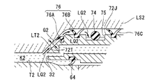
図3Aは第2回収流路44の近傍を模式的に示す図である。図3Aに示すように、第2ノズル部材72に形成された第2回収流路44の一部には、第2回収口42よりも上方に屈曲する屈曲部44Rが設けられている。また、第2回収流路44と第2回収管43との接続部は屈曲部44Rよりも下方に設けられている。すなわち、第2回収口42から回収された第2液体LQ2は、ほぼ水平方向に流れた後、上方に向かって流れ、その後下方に向かって流れた後、第2回収管43に流入する。そして、屈曲部44Rの上部には、第2回収流路44の内部と外部とを流通する孔44Kが設けられている。孔44Kによって、第2回収流路44は大気開放されている。大気開放用の孔44Kを設けたことにより、第2液体回収部41によって第2空間K2を吸引した場合であっても、第2空間K2(鏡筒PK内部の空間)が負圧になることを防止することができる。すなわち、第2液体回収部41の吸引動作によって、第2空間K2及びその第2空間K2に接続する第2回収流路44の圧力が低下すると、図3Bに示すように、孔44Kを介して第2回収流路44に気体が流入する。したがって、第2空間K2やその第2空間K2に接続する第2回収流路44が負圧になることを防止することができる。このように、第2回収口42及び第2回収流路44と第2回収管43との接続部よりも高い位置に、孔44Kを有する屈曲部44Rを設けてオーバーフロー構造とすることによって、第2空間K2が負圧になることを防止することができる。なお、大気開放用の孔44Kに、前述した多孔部材22Pを取り付けてもよい。この多孔部材を取り付けることにより、第2液体回収部41の吸引動作時の気化熱の発生を抑制することができる。
FIG. 3A is a diagram schematically showing the vicinity of the second
図4は第2ノズル部材72を上から見た断面図である。図4に示すように、本実施形態において、第2供給口32は第2空間K2の+X側に設けられており、第2回収口42は第2空間K2の−X側に設けられている。第2供給口32は所定幅を有するスリット状であり、第2回収口42は第2供給口32と同等かそれよりも大きく形成されている。第2回収口42を第2供給口32よりも大きく形成することで、液体回収を円滑に行うことができる。なお、第2回収口42に、第1回収口22同様、多孔部材を配置してもよい。
FIG. 4 is a cross-sectional view of the
なお、第2供給口32、第2回収口42の数及び配置、第2供給流路34、第2回収流路44の数及び配置などは任意に設定可能である。例えば、第2供給口32を第2ノズル部材72の複数の所定位置のそれぞれに形成してもよい。同様に、第2回収口42を第2ノズル部材72の複数の所定位置のそれぞれに形成してもよい。また、例えば図5に示すように、第2供給流路34を第2ノズル部材72の周方向に沿って形成し、第2供給流路34の長さを比較的長く設けてもよい。こうすることにより、第2空間K2に供給される第2液体LQ2は、第2ノズル部材72の温度、ひいてはその第2ノズル部材72に接続されている鏡筒PKの温度とほぼ同じ温度に調整された後、第2供給口32を介して第2空間K2に供給される。なお、図5では、第2供給流路34は第2ノズル部材72の周方向に半周分だけ形成された構成であるが、例えば全周にわたって形成されていてもよいし、螺旋状に形成されていてもよい。
The number and arrangement of the
制御装置CONTは、第2液体LQ2の液浸領域LR2を形成する際、第2液浸機構2の第2液体供給機構30及び第2液体回収機構40を使って第2空間K2に対する第2液体LQ2の供給及び回収を行う。第2空間K2に第2液体LQ2を供給するときには、制御装置CONTは、第2液体供給部31より第2液体LQ2を送出し、供給管33、及び第2ノズル部材72の第2供給流路34を介して、第2供給口32より第2空間K2に第2液体LQ2を供給する。第2空間K2の第2液体LQ2を回収するときには、制御装置CONTは第2液体回収部41を駆動する。第2液体回収部41が駆動することにより、第2空間K2の第2液体LQ2は、第2光学素子LS2の下面T3よりも高い位置に設けられた第2回収口42を介して第2ノズル部材72の第2回収流路44に流入し、回収管43を介して第2液体回収部41に回収される。第2液体LQ2は、第2光学素子LS2の下面T3と、第1光学素子LS1の上面T2との間の第2空間K2に満たされて第2液浸領域LR2を形成する。
When forming the liquid immersion region LR2 of the second liquid LQ2, the control device CONT uses the second
図2に戻って、第1光学素子LS1の上面T2と第2ノズル部材72の下面72Kとの間にはシール部材64が設けられている。更に、保持部材60の上面60Jと第2ノズル部材72の下面72Kとの間にもシール部材63が設けられている。シール部材63、64は、第2空間K2とその外側の空間との間の第2液体LQ2の流通を抑制するものであって、特に、第2空間K2に満たされた第2液体LQ2が外側の空間へ流出することを抑制している。シール部材63、64は、主に、第2空間K2に満たされた第2液体LQ2が鏡筒PKの外側の第4空間K4に流出することを抑制する。なお、シール部材64は、保持部材60の上面60Jと第2ノズル部材72の下面72Kとの間に設けても良い。
Returning to FIG. 2, a
シール部材63、64は、第2液体LQ2の流通を抑制できるものであればよく、Oリング、Vリング、Cリング、撥水性を有するリング状のシート部材などによって構成可能である。本実施形態においては、シール部材64はVリングであり、シール部材63はOリングである。なお、シール部材64を省略し、後述する撥水処理によって第2液体LQ2の流通を抑制してもよい。
The
また、第2ノズル部材72の内側面72Tと第2光学素子LS2の側面LT2との間のギャップG2にも、シール部材76Aが設けられており、第2ノズル部材72の上面72Jと、その上面72Jと対向する第2光学素子LS2のフランジ面F2との間にもシール部材76B、76Cが設けられている。シール部材76Bとシール部材76Cとは、第2光学素子LS2の光軸を中心とした同心円状に配置されている。これらシール部材76(76A、76B、76C)も、第2空間K2とその外側の空間との間の第2液体LQ2の流通を抑制するものであって、第2空間K2に満たされた第2液体LQ2が外側の空間へ流出することを抑制している。シール部材76は、主に、第2空間K2に満たされた第2液体LQ2が、第2光学素子LS2の上面T4側の第3空間(鏡筒PKの内側の空間)K3に流出することを抑制するとともに、鏡筒PKの外側の第4空間K4に流出することを抑制する。なお、第2空間K2に満たされた第2液体LQ2が第3空間K3に流出する恐れがない場合には、これらシール部材76を省略することができる。
A
図6は第2ノズル部材72を上から見た平面図である。ノズル部材72の上面72Jのうち、シール部材76(76B)の外側には、第2空間K2より流出した第2液体LQ2を保持するための凹部75が設けられている。凹部75は、第2ノズル部材72の上面72Jにおいて環状に形成されている。図7に示す模式図のように、仮に第2空間K2の第2液体LQ2がギャップG2等を介してシール部材76の外側に流出しても、凹部75によってその第2液体LQ2を保持することができる。したがって、流出する第2液体LQ2による被害の拡大を抑えることができる。
FIG. 6 is a plan view of the
また、第2ノズル部材72に形成された凹部75には、第2空間K2から第2液体LQ2が流出したか否かを検出する検出器74が設けられている。検出器74は光ファイバによって構成されており、図6に示すように、第2ノズル部材72に形成された凹部75に配置されている。
The
図8及び図9を参照しながら、第2液体LQ2を検出する検出器74の検出原理について説明する。図8は一般的な光ファイバを示す概略構成図である。図8において、光ファイバ74’は、光を伝搬するコア部74Cと、コア部74Cの周囲に設けられ、コア部74Cより小さい屈折率を有するクラッド部74Dとを備えている。光ファイバ74’では、光はクラッド部74Dより高い屈折率を有するコア部74Cに閉じ込められて伝搬される。
The detection principle of the
図9は本実施形態に係る光ファイバ74を示す概略構成図である。図9において、光ファイバ74は、光を伝搬するコア部74Cを有しており、その周囲にはクラッド部が設けられていない光ファイバ(クラッドレスファイバ)である。光ファイバ74のコア部74Cは、その周囲の気体(本実施形態では空気)より高い屈折率を有し、且つ第2液体(本実施形態では純水)LQ2より低い屈折率を有している。そのため、光ファイバ74の周囲が空気で満たされている場合、光は空気より高い屈折率を有するコア部74Cに閉じ込められて伝搬される。つまり、光ファイバ74の入射端部から入射した光はその光量を大きく減衰せずに射出端部より射出する。ところが、第2液体(純水)LQ2が光ファイバ74の表面に付着した場合、その第2液体LQ2と光ファイバ74との界面で全反射が生じないため、光は光ファイバ74の液体付着部分から外部に漏洩する。したがって、光ファイバ74の入射端部から入射した光は射出端部より射出する際の光量を減衰させる。そこで、露光装置EXの所定位置にこの光ファイバ74を設置しておき、この光ファイバ74の射出端部の光量を計測することで、制御装置CONTは、光ファイバ74に第2液体LQ2が付着したかどうか、つまり第2液体LQ2が流出したかどうかを検出することができる。なお、空気の屈折率は1程度であり、水の屈折率は1.4〜1.6程度であるため、コア部74Cは例えば1.2程度の屈折率を有する材料により構成されていることが好ましい。
FIG. 9 is a schematic configuration diagram showing an
また、光ファイバ74の射出端部より射出する光の減衰量によって、光ファイバ74は第2液体LQ2の量についても検知することができる。すなわち、光ファイバ74の周囲に少量の第2液体LQ2が付着した場合には射出端部における光の減衰量は小さく、大量の第2液体LQ2が付着した場合には減衰量は大きい。したがって、光ファイバ74の射出端部における光量を計測することによって、第2液体LQ2の漏洩量を検出することができる。更に、光ファイバ射出端部における光量の計測値を予め設定した複数のしきい値(基準値)と比較し、各しきい値を越えた場合にそれぞれ特定の信号を発するようにすることにより、第2液体LQ2の漏洩量を段階的に検出することができる。
Further, the
そして、図6に示すように、検出器(光ファイバ)74が第2ノズル部材72に形成された凹部75に設けられている。すなわち、光ファイバ74は、シール部材76Bとシール部材76Cとの間に配置されている。そして、光ファイバ74の入射端部には、光ファイバ74に対して光を入射可能な投光部77が接続され、光ファイバ74の射出端部には、光ファイバ74を伝搬して射出端部より射出した光を受光可能な受光部78が接続されている。なお図では、光ファイバ74の一部とシール部材76Cとが重なっているように示されているが、この部分においては、例えば第2ノズル部材72の上面に設けられた切欠部に光ファイバ74の一部が配置されており、光ファイバ74の一部とシール部材76とが干渉しないように、且つシール部材76Cによる気密性は確保されている。制御装置CONTは、投光部77から光ファイバ74に入射したときの光の光量と、受光部78で受光した光の光量とに基づいて、光ファイバ74の入射端部に対する射出端部の光の減衰率を求め、その求めた結果に基づいて、光ファイバ74に第2液体LQ2が付着したかどうか、すなわち第2空間K2の外側に第2液体LQ2が流出したかどうかを判断する。そして、制御装置CONTは、第2液体LQ2が流出したと判断したとき、第2液体供給機構30による第2液体LQ2の供給動作を停止したり、第2液体回収機構40による第2液体LQ2の回収力を上昇したり、露光装置EXを構成する電気機器に対する電力供給を停止したり、第2空間K2に供給される第2液体LQ2の供給量、あるいは第2空間K2から排出される第2液体LQ2の排水量を調整する等の適切な処置を講ずればよい。
As shown in FIG. 6, the detector (optical fiber) 74 is provided in the
制御装置CONTは、検出器74の検出結果に基づいて、上述したような適切な処置を講ずることにより、第2空間K2から流出した第2液体LQ2が、第2光学素子LS2の上面T4側の第3空間K3に流入することを抑制できる等、流出する第2液体LQ2の被害の拡大を抑制することができる。第3空間K3は、鏡筒PKの内側の空間であって、所定のガス環境に維持されている。そのような第3空間K3に第2液体LQ2が浸入すると、ガス環境を乱して投影光学系PLの結像特性に影響を及ぼす。したがって、第2液体LQ2を検出可能な検出器74を設けておき、検出器74が第2液体LQ2の流出を検出したときには、上述した処置を講ずることで、第3空間K3に第2液体LQ2が浸入する不都合を防止することができる。更に本実施形態においては、シール部材76Bやシール部材76Cが設けられているので、第2空間K2の第2液体LQ2が第3空間K3に流入する不都合の発生が抑えられている。
Based on the detection result of the
なお、第2ノズル部材72の内側面72Tと第2光学素子LS2の側面LT2との間に設けるシール部材76Aは、同心円上に複数設けることが好ましい。また、第2ノズル部材72の上面72Jと、その上面72Jと対向する第2光学素子LS2のフランジ面F2との間に設けるシール部材76Bも、同心円上に複数設けることが好ましい。こうすることにより、第2空間K2に満たされた第2液体LQ2が第3空間K3や第4空間K4に流出することをより確実に抑制することができる。なお、シール部材76Aを複数設けた場合には、シール部材76Bを省略してもよい。また、シール部材76Bを複数設けた場合には、シール部材76Aを省略してもよい。
A plurality of
なお、ここでは、検出器74は凹部75の内側に円環状に配置されているが、例えば凹部75の一部に穴部(サンプリングポート)を設け、そのサンプリングポートに接続する凹部75とは別の空間(計測空間)に検出器74を配置し、サンプリングポートを介して計測空間に流入した第2液体LQ2を、計測空間に配置されている検出器74で検出するようにしてもよい。
Here, the
なお、検出器74は、第2空間K2からの第2液体LQ2の流出、あるいは第3空間K3への第2液体LQ2の流入を検出可能な位置であれば、第2ノズル部材72の上面72Jに限らず、任意の位置に設けることができる。
Note that the
第1光学素子LS1を保持する保持部材60の所定位置には、第2空間K2の第2液体LQ2を排出するための貫通孔65が設けられている。また、貫通孔65には、その貫通孔65を塞ぐ蓋66が配置されている。貫通孔65は、保持部材60の上面60Jと下面60Kとを貫通するものである。ここで、保持部材60の上面60Jは、保持した第1光学素子LS1の上面T2よりも低い位置に設けられている。したがって、貫通孔65の上端部は、第1光学素子LS1の上面T2よりも低い位置に設けられている。
A through
次に、上述した構成を有する露光装置EXを用いてマスクMのパターン像を基板Pに露光する方法について説明する。 Next, a method for exposing the pattern image of the mask M onto the substrate P using the exposure apparatus EX having the above-described configuration will be described.
基板Pの露光を行うに際し、制御装置CONTは、第2液体供給機構30より第2空間K2に第2液体LQ2を供給するとともに、第2液体回収機構40により第2空間K2の第2液体LQ2を回収する。第2液体供給機構30による液体供給動作、及び第2液体回収機構40による液体回収動作によって、第1光学素子LS1の上面T2のうち露光光ELが通過する所定領域AR2を含む領域が第2液浸領域LR2となるように、第1光学素子LS1の上面T2と第2光学素子LS2との間が第2液体LQ2で満たされる。
When performing the exposure of the substrate P, the control device CONT supplies the second liquid LQ2 from the second
第2液浸領域LR2の形成開始時において、第2空間K2の第2液体LQ2中に気体部分(気泡)が形成される可能性がある。気泡は異物として作用するため、第2液浸領域LR2の第2液体LQ2中に気泡(例えば直径0.1mm以上の気泡)が存在していると、パターン転写精度の劣化を招く。ところが、本実施形態においては、第2液浸領域LR2の形成開始時において、第2液体供給機構30及び第2液体回収機構40による液体の供給及び回収を並行して行い、第2液体回収機構40の第2回収口42は、第2光学素子LS2の下面T3よりも高い位置に設けられているので、図10に示す模式図のように、仮に第2液体LQ2中に気泡が存在していても、気泡は第2液体LQ2との比重の差によって上方に移動するとともに、第2液体供給機構30及び第2液体回収機構40による第2液体LQ2の供給及び回収動作によって生成された第2液体LQ2の流れによって、第2回収口42から円滑に回収される。したがって、第2液浸領域LR2の第2液体LQ2中に気泡が残留することを抑制することができる。また、第2液体回収機構40は、第2液体LQ2中の気泡に限らず、第2液体LQ2よりも比重が小さい異物を第2回収口42を介して円滑に回収できる。
At the start of the formation of the second immersion region LR2, there is a possibility that a gas portion (bubble) is formed in the second liquid LQ2 of the second space K2. Since the bubbles act as foreign matters, if there are bubbles (for example, bubbles having a diameter of 0.1 mm or more) in the second liquid LQ2 of the second immersion region LR2, the pattern transfer accuracy is deteriorated. However, in the present embodiment, at the start of formation of the second liquid immersion region LR2, the liquid supply and recovery by the second
そして、第2液浸領域LR2が形成された後、制御装置CONTは、第2液体供給機構30による第2液体LQ2の供給を停止する。第1光学素子LS1と第2光学素子LS2との間の第2液体LQ2は第2空間K2内部に保持され、第2液浸領域LR2は維持される。
Then, after the second liquid immersion region LR2 is formed, the control device CONT stops the supply of the second liquid LQ2 by the second
ロード位置において基板Pが基板ステージPSTにロードされた後、制御装置CONTは、基板Pを保持した基板ステージPSTを投影光学系PLの下、すなわち露光位置に移動する。そして、基板ステージPSTと投影光学系PLの第1光学素子LS1とを対向させた状態で、制御装置CONTは、第1液体供給機構10による単位時間あたりの第1液体LQ1の供給量及び第1液体回収機構20による単位時間あたりの第1液体LQ1の回収量を最適に制御しつつ、第1液体供給機構10及び第1液体回収機構20による液体LQ1の供給及び回収を行い、第1空間K1のうち、少なくとも露光光ELの光路上に第1液体LQ1の第1液浸領域LR1を形成し、その露光光ELの光路を第1液体LQ1で満たす。
After the substrate P is loaded onto the substrate stage PST at the load position, the control device CONT moves the substrate stage PST holding the substrate P to the exposure optical position, that is, below the projection optical system PL. Then, with the substrate stage PST and the first optical element LS1 of the projection optical system PL facing each other, the control device CONT supplies the first liquid LQ1 supplied per unit time and the first liquid LQ1 by the first
ここで、基板ステージPST上の所定位置には、例えば特開平4−65603号公報に開示されているような基板アライメント系、及び特開平7−176468号公報に開示されているようなマスクアライメント系によって計測される基準マークを備えた基準部材(計測部材)が設けられている。更に、基板ステージPST上の所定位置には、光計測部として例えば特開昭57−117238号公報に開示されているような照度ムラセンサ、例えば特開2002−14005号公報に開示されているような空間像計測センサ、及び例えば特開平11−16816号公報に開示されているような照射量センサ(照度センサ)などが設けられている。制御装置CONTは、基板Pの露光処理を行う前に、基準部材上のマーク計測や、光計測部を使った各種計測動作を行い、その計測結果に基づいて、基板Pのアライメント処理や、投影光学系PLの結像特性調整(キャリブレーション)処理を行う。例えば光計測部を使った計測動作を行う場合には、制御装置CONTは、基板ステージPSTをXY方向に移動することで第1液体LQ1の第1液浸領域LR1に対して基板ステージPSTを相対的に移動し、光計測部上に第1液体LQ1の第1液浸領域LR1を配置し、その状態で第1液体LQ1及び第2液体LQ2を介した計測動作を行う。 Here, at a predetermined position on the substrate stage PST, for example, a substrate alignment system as disclosed in JP-A-4-65603 and a mask alignment system as disclosed in JP-A-7-176468. A reference member (measurement member) provided with a reference mark measured by is provided. Further, at a predetermined position on the substrate stage PST, an illuminance unevenness sensor as disclosed in, for example, Japanese Patent Application Laid-Open No. 57-117238, for example, as disclosed in Japanese Patent Application Laid-Open No. 2002-14005, as an optical measurement unit. An aerial image measurement sensor and a dose sensor (illuminance sensor) as disclosed in, for example, Japanese Patent Laid-Open No. 11-16816 are provided. Before the exposure processing of the substrate P, the control device CONT performs mark measurement on the reference member and various measurement operations using the optical measurement unit, and based on the measurement results, alignment processing and projection of the substrate P are performed. An imaging characteristic adjustment (calibration) process of the optical system PL is performed. For example, when performing a measurement operation using the optical measurement unit, the control device CONT moves the substrate stage PST in the XY directions to move the substrate stage PST relative to the first immersion region LR1 of the first liquid LQ1. The first immersion region LR1 of the first liquid LQ1 is arranged on the optical measurement unit, and the measurement operation via the first liquid LQ1 and the second liquid LQ2 is performed in that state.
上記アライメント処理及びキャリブレーション処理を行った後、制御装置CONTは、第1液体供給機構10による基板P上に対する第1液体LQ1の供給と並行して、第1液体回収機構20による基板P上の第1液体LQ1の回収を行いつつ、基板Pを保持する基板ステージPSTをX軸方向(走査方向)に移動しながら、投影光学系PL、第1光学素子LS1の上面T2側に形成された第2液浸領域LR2の第2液体LQ2、及び第1光学素子LS1の下面T1側に形成された第1液浸領域LR1の第1液体LQ1を介して基板P上に露光光ELを照射して、マスクMのパターン像を基板P上に露光する。
After performing the alignment process and the calibration process, the controller CONT performs the first
基板Pの露光中においては、第2液浸機構2による第2液体LQ2の供給動作及び回収動作は行われない。すなわち、第2空間K2に溜められた状態の第2液体LQ2を介して露光が行われる。基板Pの露光中に第2液体LQ2の供給及び回収を行わないようにすることで、基板Pの露光中には、第2液体LQ2の供給及び回収に伴う振動が発生しない。したがって、振動に起因する露光精度の劣化を防止することができる。
During the exposure of the substrate P, the supply operation and the recovery operation of the second liquid LQ2 by the
本実施形態においては、レンズ作用を有する第2光学素子LS2の下に、平行平面板からなる第1光学素子LS1が配置されているが、第1光学素子LS1の下面T1側の第1空間K1、及び上面T2側の第2空間K2のそれぞれに第1液体LQ1、及び第2液体LQ2を満たすことで、第2光学素子LS2の下面T3や第1光学素子LS1の上面T2での反射損失が低減され、大きな像側開口数を確保した状態で、基板Pを良好に露光することができる。 In the present embodiment, the first optical element LS1 made of a plane-parallel plate is disposed under the second optical element LS2 having a lens action, but the first space K1 on the lower surface T1 side of the first optical element LS1. And the second space K2 on the upper surface T2 side is filled with the first liquid LQ1 and the second liquid LQ2, respectively, thereby causing a reflection loss on the lower surface T3 of the second optical element LS2 and the upper surface T2 of the first optical element LS1. The substrate P can be satisfactorily exposed in a state of being reduced and ensuring a large image-side numerical aperture.
基板Pの露光が終了すると、制御装置CONTは、第1液体供給機構10による第1液体LQ1の供給を停止し、第1液体回収機構20等を使って、第1液浸領域LR1の第1液体LQ1(第1空間K1の第1液体LQ1)を回収する。更に、制御装置CONTは、第1液体回収機構20の第1回収口22等を使って基板P上や基板ステージPST上に残留している第1液体LQ1を回収する。
When the exposure of the substrate P is completed, the control device CONT stops the supply of the first liquid LQ1 by the first
また、制御装置CONTは、基板Pの露光が終了した後、第2空間K2に形成されている第2液浸領域LR2の第2液体LQ2を、第2液体回収機構40の第2回収口42を介して回収するとともに、新たな第2液体LQ2を第2液体供給機構30の第2供給口32より第2空間K2に供給する。これにより、第2空間K2に満たされる第2液体LQ2が交換される。この第2液体LQ2の回収及び供給の動作を所定時間行うことにより、第2空間K2の第2液体を新たなものに置き換えることができる。なお、第2空間K2の第2液体を新たなものに置き換える場合、シール部材64を省略し、保持部材60に設けられた貫通孔65を介して、第2液体LQを排出してもよい。
In addition, after the exposure of the substrate P is finished, the control device CONT uses the second liquid LQ2 in the second liquid immersion area LR2 formed in the second space K2 as the
基板P上の第1液体LQ1が回収された後、制御装置CONTは、その基板Pを支持した基板ステージPSTをアンロード位置まで移動し、基板Pを基板ステージPSTよりアンロードするそして、次に露光処理されるべき基板Pが基板ステージPSTにロードされる。制御装置CONTは、上述と同様のシーケンスでその基板Pを露光する。 After the first liquid LQ1 on the substrate P is collected, the control device CONT moves the substrate stage PST supporting the substrate P to the unload position, unloads the substrate P from the substrate stage PST, and then The substrate P to be exposed is loaded onto the substrate stage PST. The control device CONT exposes the substrate P in the same sequence as described above.
なお、本実施形態においては、露光する基板P毎に第2空間K2の第2液体LQ2を交換する構成であるが、第2空間K2の第2液体LQ2の温度変化や清浄度の劣化等が露光精度に影響を与えない程度であれば、所定時間間隔毎や所定処理基板枚数毎に、第2空間K2の第2液体LQ2を交換するようにしてもよい。 In the present embodiment, the second liquid LQ2 in the second space K2 is exchanged for each substrate P to be exposed. However, the temperature change of the second liquid LQ2 in the second space K2, deterioration in cleanliness, etc. As long as the exposure accuracy is not affected, the second liquid LQ2 in the second space K2 may be replaced every predetermined time interval or every predetermined number of processed substrates.
なお、基板Pの露光中や露光前後においても、第2液体LQ2の供給及び回収を連続的に行うようにしてもよい。第2液体LQ2の供給及び回収を連続的に行うことで、常に第2空間K2を温度管理された清浄な第2液体LQ2で満たすことができる。この場合においても、仮に液体中に気泡が配置されても、第2回収口42を介してその気泡を円滑に回収することができる。一方、本実施形態のように、第2空間K2に第2液体LQ2を溜めた状態で露光し、第2空間K2に対する第2液体LQ2の交換を間欠的に行うことで、上述したように、基板Pの露光中には、第2液体LQ2の供給及び回収に伴う振動が発生しない。また、基板Pの露光中に第2液体LQ2の供給及び回収を連続的に行う構成では、例えば単位時間あたりの第2液体LQ2の供給量及び回収量が不安定になった場合、第2空間K2の第2液体LQ2が流出あるいは飛散し、被害が拡大する可能性がある。また、単位時間あたりの第2液体LQ2の供給量及び回収量が不安定になった場合、第2液浸領域LR2が枯渇し、露光精度が劣化する不都合が生じる。そのため、第2空間K2に対する第2液体LQ2の交換を間欠的に行うことで、第2液浸領域LR2を所望状態に形成し、上記不都合の発生を防止することができる。なお、第2空間K2に対する第2液体LQ2の交換を間欠的に行う場合には、上述したように露光中には振動が発生しないので、第2ノズル部材72と第2光学素子LS2とが接触していてもよい。
Note that the supply and recovery of the second liquid LQ2 may be continuously performed during the exposure of the substrate P and before and after the exposure. By continuously supplying and collecting the second liquid LQ2, the second space K2 can always be filled with the clean second liquid LQ2 whose temperature is controlled. Even in this case, even if bubbles are disposed in the liquid, the bubbles can be smoothly recovered through the
以上説明したように、第1光学素子LS1の下面T1と基板Pとの間の第1空間K1を第1液体LQ1で満たすとともに、第1光学素子LS1の上面T2と第2光学素子LS2の下面T3との間の第2空間K2も第2液体LQ2で満たすことで、マスクMを通過した露光光ELを基板Pまで良好に到達させ、基板Pを良好に露光することができる。また、第1光学素子LS1の下面T1側の第1液体LQ1は基板Pと接触するため、その第1液体LQ1に接触する第1光学素子LS1が汚染する可能性が高くなるが、第1光学素子LS1は容易に交換可能であるため、汚染された第1光学素子LS1のみを新たなもの(清浄なもの)と交換すればよく、清浄な第1光学素子LS1を備えた投影光学系PL及び第1、第2液体LQ1、LQ2を介した露光及び計測を良好に行うことができる。 As described above, the first space K1 between the lower surface T1 of the first optical element LS1 and the substrate P is filled with the first liquid LQ1, and the upper surface T2 of the first optical element LS1 and the lower surface of the second optical element LS2 are filled. By filling the second space K2 between T3 and the second liquid LQ2, the exposure light EL that has passed through the mask M can reach the substrate P satisfactorily, and the substrate P can be exposed satisfactorily. Further, since the first liquid LQ1 on the lower surface T1 side of the first optical element LS1 is in contact with the substrate P, there is a high possibility that the first optical element LS1 in contact with the first liquid LQ1 is contaminated. Since the element LS1 can be easily replaced, only the contaminated first optical element LS1 needs to be replaced with a new one (clean), and the projection optical system PL including the clean first optical element LS1 and Exposure and measurement through the first and second liquids LQ1 and LQ2 can be performed satisfactorily.
そして、第2液浸機構2の第2回収口42は、第2光学素子LS2の下面T3よりも高い位置に設けられているため、仮に、第1光学素子LS1の上面T2と第2光学素子LS2の下面T3との間に満たされた第2液体LQ2中に気泡(気体部分)が存在していても、気泡と第2液体LQ2との比重の差によって気泡は上方へ移動するため、第2光学素子LS2の下面T3よりも高い位置に設けられた第2回収口42は気泡を円滑に回収できる。したがって、第2液体LQ2中の気泡を除去した状態で、露光処理及び計測処理を良好に行うことができる。
Since the
また、第1光学素子LS1と第2光学素子LS2との間の第2空間K2から第2液体LQ2が流出したか否かを検出する検出器74を設けたので、検出器74が第2液体LQ2を検出したときには、流出する第2液体LQ2の被害の拡大を抑制するための適切な処置を迅速に講ずることができる。したがって、機器の誤作動や露光精度及び計測精度の劣化といった不都合の発生を防止できる。
In addition, since the
なお、上述した実施形態においては、第2ノズル部材72の内側面72Tは、第2光学素子LS2の側面LT2に沿った傾斜を有しているが、図11に示すように、第2ノズル部材72の内側面72Tを鉛直方向とほぼ平行となるように形成し、第2ノズル部材72の内側面72Tの下端部と、第2光学素子LS2の下面T3近傍との距離を、他の部分の距離よりも広くなるように設けてもよい。こうすることにより、第2回収口42を介して気泡を回収しやすくなる。
In the above-described embodiment, the
なお、上述した実施形態においては、図10及び図11に示すように、第2回収口42の全部が下面T3よりも高い位置に設けられているが、図12に示す模式図のように、第2回収口42の少なくとも一部が下面T3よりも高い位置にある構成であってもよい。一方、上述した実施形態のように、第2回収口42の全部を下面T3よりも高い位置に設けることにより、より円滑に気泡を回収(除去)することができる。
In the above-described embodiment, as shown in FIGS. 10 and 11, the entire
なお、上述した実施形態においては、第2光学素子LS2の下面T3は平面状であり、第2回収口42はその平面状の下面T3よりも高い位置に設けられていればよいが、図13に示すように、例えば第2光学素子LS2の下面T3が下向きに凸状である場合も考えられる。この場合、第2回収口42は、図13に示す模式図のように、下面T3の凸領域R1のエッジE1よりも高い位置にあることが好ましい。なお、図14の模式図に示すように、第2回収口42は、下面T3のうち、露光光ELが通過する所定領域AR2において最も高い位置E2よりも高い位置に配置された構成であってもよい。こうすることにより、少なくとも露光光ELが通過する領域AR2において気泡が存在する不都合を防止することができる。
In the above-described embodiment, the lower surface T3 of the second optical element LS2 is planar, and the
<第2の実施形態>
次に、第2の実施形態として、第1光学素子LS1を交換する手順について説明する。
第1液浸領域LR1(第1空間K1)の第1液体LQ1中に、例えば感光剤(フォトレジスト)に起因する異物など、基板P上から発生した不純物等が混入することによって、その第1液体LQ1が汚染する可能性がある。第1液浸領域LR1の第1液体LQ1は第1光学素子LS1の下面T1にも接触するため、その汚染された第1液体LQ1によって、第1光学素子LS1の下面T1が汚染する可能性がある。また、空中を浮遊している不純物が、投影光学系PLの像面側に露出している第1光学素子LS1の下面T1に付着する可能性もある。そこで、汚染された第1光学素子LS1は、所定のタイミングで交換される。<Second Embodiment>
Next, a procedure for replacing the first optical element LS1 will be described as a second embodiment.
The first liquid LQ1 in the first liquid immersion area LR1 (first space K1) is mixed with impurities generated from the substrate P such as foreign matters caused by the photosensitive agent (photoresist), for example, and the first liquid LQ1 is mixed with the first liquid LQ1. The liquid LQ1 may be contaminated. Since the first liquid LQ1 in the first immersion region LR1 also contacts the lower surface T1 of the first optical element LS1, the lower surface T1 of the first optical element LS1 may be contaminated by the contaminated first liquid LQ1. is there. Further, there is a possibility that impurities floating in the air adhere to the lower surface T1 of the first optical element LS1 exposed on the image plane side of the projection optical system PL. Therefore, the contaminated first optical element LS1 is replaced at a predetermined timing.
第1光学素子LS1を交換する前に、第1ノズル部材71を取り外す。そして、第1光学素子LS1を交換するときには、上述したように、ボルト61よる第2ノズル部材72に対する保持部材60の接続(固定)を解除するが、その解除の前に、第2空間K2に存在する第2液体LQ2の除去作業(抜き取り作業)が行われる。具体的には、図15に示すように、まず、貫通孔65に配置されている蓋66が取り外される。なお、第1の実施形態で述べたように、シール部材64は無くてもよいため、図15においてはシール部材64は設けられていない。蓋66が取り外されることにより、第2空間K2に満たされている第2液体LQ2、すなわち第1光学素子LS1の上面T2に形成されていた第2液浸領域LR2の第2液体LQ2は、貫通孔65を介して外部に排出される。ここで、貫通孔65の下端部に、液体回収機器68を配置し、貫通孔65を介して排出された第2液体LQ2は、液体回収機器68に回収される。液体回収機器68は、貫通孔65の下端部に接続する回収口68Aと、回収された第2液体LQ2を収容な可能なタンク68Cと、回収口68Aとタンク68Cとを接続するチューブ部材68Bとを備えている。
Before replacing the first optical element LS1, the
第2液体回収機構40の第2回収口42は、第2光学素子LS2の下面T3よりも高い位置に設けられているため、第2液体回収機構40を使って第2空間K2の第2液体LQ2を完全に除去することは困難である。そこで、保持部材60に設けられている貫通孔65を使って第2空間K2の第2液体LQ2が排出される。貫通孔65の上端部は、第1光学素子LS1の上面T2よりも低い位置に設けられているため、重力作用により、第2空間K2の第2液体LQ2を貫通孔65を介して外部に良好に排出することができる。そして、第2空間K2の第2液体LQ2をほぼ全て排出した後、ボルト61による第2ノズル部材72と保持部材60との接続を解除する。こうすることにより、第2液体LQ2を露光装置EXを構成する機器や部材(例えば基板ステージPSTを駆動するリニアモータ等)に飛散させることなく、第1光学素子LS1を鏡筒PKから取り外すことができる。そして、新たな(清浄な)第1光学素子LS1を取り付ける際には、スペーサ部材62を適宜配置して第2光学素子LS2に対する第1光学素子LS1の位置関係を調整しつつ、第1光学素子LS1を保持する保持部材60を第2ノズル部材72に取り付ける。なお図では、貫通孔65は1つであるが、もちろん、保持部材60の任意の複数位置のそれぞれに貫通孔65を設けることができる。
Since the
本実施形態においては、第1光学素子LS1は、鏡筒PKに対して容易に取り付け・外し可能(交換可能)となっているため、その汚染された第1光学素子LS1のみを清浄な第1光学素子LS1と交換することで、光学素子の汚染に起因する露光精度及び投影光学系PLを介した計測精度の劣化を防止できる。一方、第2空間K2の第2液体LQ2は基板Pに接触しないようになっている。また、第2空間K2は、第1光学素子LS1、第2光学素子LS2、及び鏡筒PKで囲まれたほぼ閉空間であるため、空中を浮遊している不純物は第2空間K2の第2液体LQ2に混入し難く、第2光学素子LS2の下面T3や第1光学素子LS1の上面T2には不純物が付着し難い。したがって、第2光学素子LS2の下面T3や第1光学素子LS1の上面T2の清浄度は維持されている。したがって、第1光学素子LS1を交換するのみで、投影光学系PLの透過率の低下等を防止して露光精度及び計測精度を維持することができる。 In the present embodiment, the first optical element LS1 is easily attachable / detachable (replaceable) with respect to the lens barrel PK, so that only the contaminated first optical element LS1 is clean first. By exchanging with the optical element LS1, it is possible to prevent deterioration of exposure accuracy and measurement accuracy via the projection optical system PL due to contamination of the optical element. On the other hand, the second liquid LQ2 in the second space K2 does not come into contact with the substrate P. In addition, since the second space K2 is a substantially closed space surrounded by the first optical element LS1, the second optical element LS2, and the lens barrel PK, the impurities floating in the air are the second in the second space K2. It is difficult to mix with the liquid LQ2, and impurities are difficult to adhere to the lower surface T3 of the second optical element LS2 and the upper surface T2 of the first optical element LS1. Therefore, the cleanliness of the lower surface T3 of the second optical element LS2 and the upper surface T2 of the first optical element LS1 is maintained. Therefore, by only replacing the first optical element LS1, it is possible to prevent a decrease in the transmittance of the projection optical system PL and maintain exposure accuracy and measurement accuracy.
平行平面板からなる第1光学素子LS1を設けずに、第2光学素子LS2に第1液浸領域LR1の液体を接触させる構成も考えられるが、投影光学系PLの像側開口数を大きくしようとすると、光学素子の有効径を大きくする必要があり、光学素子LS2を大型化せざるを得なくなる。光学素子LS2の周囲には、上述したようなノズル部材や、不図示ではあるがアライメント系などといった各種計測装置が配置されるため、そのような大型の光学素子LS2を交換することは、交換作業が困難である更に、光学素子LS2は屈折力(レンズ作用)を有しているため、投影光学系PL全体の光学特性(結像特性)を維持するために、その光学素子LS2を高い位置決め精度で鏡筒PKに取り付ける必要がある。したがって、そのような光学素子LS2を鏡筒PKに対して頻繁に取り付け・外しする(交換する)ことは、投影光学系PLの光学特性(光学素子LS2の位置決め精度)を維持する観点からも好ましくない。本実施形態では、第1光学素子LS1として比較的小型な平行平面板を設け、その第1光学素子LS1を交換する構成であるため、作業性良く容易に交換作業を行うことができ、投影光学系PLの光学特性を維持することもできる。そして、第1光学素子LS1の下面T1側の第1空間K1及び上面T2側の第2空間K2のそれぞれに対して第1、第2液体LQ1、LQ2を独立して供給及び回収可能な第1、第2液浸機構1、2を設けたことにより、第1、第2液体LQ1、LQ2の清浄度を維持しつつ、照明光学系ILから射出された露光光ELを投影光学系PLの像面側に配置された基板Pまで良好に到達させることができる。
Although a configuration in which the liquid in the first immersion area LR1 is brought into contact with the second optical element LS2 without providing the first optical element LS1 made of a plane-parallel plate is possible, the image side numerical aperture of the projection optical system PL should be increased. Then, it is necessary to increase the effective diameter of the optical element, and the optical element LS2 must be enlarged. Since various measuring devices such as the above-described nozzle member and an alignment system (not shown) are arranged around the optical element LS2, replacing such a large optical element LS2 is a replacement operation. Furthermore, since the optical element LS2 has a refractive power (lens action), the optical element LS2 has high positioning accuracy in order to maintain the optical characteristics (imaging characteristics) of the entire projection optical system PL. It is necessary to attach to the lens barrel PK. Therefore, it is preferable to frequently attach / detach (replace) such an optical element LS2 to / from the lens barrel PK from the viewpoint of maintaining the optical characteristics of the projection optical system PL (positioning accuracy of the optical element LS2). Absent. In the present embodiment, a relatively small plane-parallel plate is provided as the first optical element LS1, and the first optical element LS1 is replaced. Therefore, the replacement operation can be easily performed with good workability, and projection optics The optical characteristics of the system PL can also be maintained. The first and second liquids LQ1 and LQ2 can be independently supplied and recovered to the first space K1 on the lower surface T1 side and the second space K2 on the upper surface T2 side of the first optical element LS1, respectively. Since the
また、第2空間K2の第2液体LQ2を貫通孔65を介して排出する際、図16に示すように、第2供給口32より気体を供給し(吹き出し)、その吹き出した気体を第1光学素子LS1の上面T2を含む第2空間K2に供給するようにしてもよい。図16に示す例においては、第2供給口32に接続する供給管33には、バルブ91を介して気体供給系90が接続されている。そして、バルブ91の切り替えにより、第2供給口32と第2液体供給部31とを接続する流路が開いているときには、第2供給口32と気体供給系90とを接続する流路が閉じられ、第2供給口32と第2液体供給部31とを接続する流路が閉じているときには、第2供給口32と気体供給系90とを接続する流路が開けられる。
貫通孔65を介した第2空間K2の液体排出作業(第1光学素子の交換作業、あるいは第2液体LQ2を新たなものに置き換える作業を含む)を行うときには、制御装置CONTは、バルブ91を駆動して、第2供給口32と気体供給系90とを接続する流路を開け、第2供給口32より第1光学素子LS1の上面T2に気体を吹き付ける。貫通孔65を介した第2空間K2の液体排出作業と並行して、気体を吹き付けることで、第1光学素子LS1の上面T2に付着している液体(液滴)は、吹き付けられた気体の流れによって、貫通孔65まで円滑に移動する。したがって、第2空間K2に存在する第2液体LQ2をより良好に除去することができる。気体を吹き付ける場合、液体排出作業の開始時には、湿度の高い気体を供給し、一定時間経過後に湿度を除去した気体(ドライエア等)を供給することが望ましい。あるいは、液体排出作業の開始時から徐々に湿度を除去した気体を供給してもよい。そうすることによって、気化熱による急激な温度低下を防ぐことができる。Further, when the second liquid LQ2 in the second space K2 is discharged through the through
When performing the liquid discharge operation (including the replacement operation of the first optical element or the operation of replacing the second liquid LQ2 with a new one) in the second space K2 through the through
なお図16に示す実施形態では、第2供給口32から気体が供給されているが、もちろん、貫通孔65が設けられている位置等に応じて、第2回収口42から気体を供給することもできる。更には、保持部材60に貫通孔を複数設け、図17に示すように、液体回収機器68が接続された貫通孔65とは別の貫通孔65’に気体供給系90’を接続し、その保持部材60に設けられた貫通孔65’を介して第2空間K2に気体を供給するようにしてもよい。このとき、貫通孔65’は保持部材60に設けられた気体吹出口として機能する。貫通孔65’から吹き出された気体は、例えば第2光学素子LS2の下面T3や、第1光学素子LS1の上面T2に吹き付けられる。したがって、それら上面T2や下面T3に付着していた第2液体LQ2を貫通孔65まで移動させることができる。
In the embodiment shown in FIG. 16, the gas is supplied from the
なお、本実施形態においては、投影光学系PLの最も像面に近い第1光学素子LS1を保持する保持部材60に貫通孔65が設けられており、その貫通孔65を介して第1光学素子LS1の上面T2に形成された第2液浸領域LR2の第2液体LQ2を排出しているが、他の光学素子(LS2〜LS7)の上面に液体の液浸領域を形成する可能性もある。そのような場合には、その上面に液体の液浸領域が形成される光学素子を保持する保持部材に貫通孔を設けることができる。
In the present embodiment, a through
<第3の実施形態>
次に、第3の実施形態を図18を参照しながら説明する。本実施形態の特徴的な部分は、第2ノズル部材72が第1光学素子LS1を真空吸着保持している点にある。図18において、第2ノズル部材72は、第1光学素子LS1を真空吸着保持する保持部100を備えている。保持部100は、第2ノズル部材72のうち、第1光学素子LS1の上面T2と対向する下面72Kに設けられている。第2ノズル部材72の下面72Kは、第1光学素子LS1の上面T2のうち露光光ELが通過する領域とは異なる領域に対向している。保持部100は、第2ノズル部材72の下面72Kに環状に形成された真空吸着溝101を含んで構成されている。真空吸着溝101の一部には、不図示の真空系に接続された吸着孔が形成されている。第2ノズル部材72の下面72Kと第1光学素子LS1の上面T2とを接触させた状態で、真空系を駆動することにより、第2ノズル部材72に設けられた保持部100は、第1光学素子LS1を真空吸着保持する。また、第2ノズル部材72には、板ばね103を含む第2保持部102が設けられている。第2保持部102は板ばね103によって第1光学素子LS1の周縁部の一部を保持可能である。こうすることにより、保持部100による第1光学素子LS1の真空吸着保持が行われなかったときに、第2保持部102が第1光学素子LS1を保持することで、第1光学素子LS1の落下を防止することができる。<Third Embodiment>
Next, a third embodiment will be described with reference to FIG. The characteristic part of this embodiment is that the
このように、第1光学素子LS1は第2ノズル部材72に設けられた保持部100によって真空吸着保持されるので、第1光学素子LS1を第2ノズル部材72に対して容易に脱着(交換)することができる。したがって、第1光学素子LS1を新たなもの(清浄なもの)と交換する交換作業を円滑に作業性良く行うことができる。また、第2ノズル部材72に保持部100を設けたので、上述した第1、第2の実施形態のような保持部材60を省略することができる。更には、第2ノズル部材72とは別に真空吸着保持部を設ける構成に比べて、装置の部品数を少なくすることができ、装置の簡略化(コンパクト化)を図ることができ、装置コストを削減することができる。
Thus, since the first optical element LS1 is vacuum-sucked and held by the holding
なお、上述した第1〜第3の実施形態において、鏡筒PKと第2ノズル部材72とは別々の部材であり、鏡筒PKの下端部に第2ノズル部材72が接続されることで、鏡筒PKと第2ノズル部材72とが一体化されているが、鏡筒PKに、第2供給口32や第2回収口42、第2供給流路34や第2回収流路44が形成されていてもよい。すなわち、鏡筒PKに第2ノズル部材72の機能を持たせてもよい。その場合、鏡筒PKの下端面に、第3の実施形態で説明したような保持部100を設けることにより、鏡筒PK(第2ノズル部材72)は、光学素子LS2〜LS7を保持するとともに、第1光学素子LS1を真空吸着保持することとなり、第1光学素子LS1を容易に脱着可能となる。
In the first to third embodiments described above, the lens barrel PK and the
なお、上述した第1〜第3の実施形態においては、第1ノズル部材71は鏡筒PKと離れているが、振動に起因する露光精度の劣化が少ないのであれば、第1ノズル部材71を鏡筒PKに固定してもよい。
In the first to third embodiments described above, the
なお、上述の第1〜第3の実施形態においては、複数の光学素子LS1〜LS7のうち、少なくとも第1、第2液体LQ1、LQ2と接触する第1、第2光学素子LS1、LS2は石英によって形成されている。石英は、水である第1、第2液体LQ1、LQ2との親和性が高いので、第1光学素子LS1の液体接触面である下面T1及び上面T2、及び第2光学素子LS2の液体接触面である下面T3のほぼ全域に第1、第2液体LQ1、LQ2を密着させることができる。したがって、第1、第2光学素子LS1、LS2の液体接触面に第1、第2液体LQ1、LQ2を密着させて、気泡の生成を抑制しつつ、第2光学素子LS2と第1光学素子LS1との間の光路を第2液体LQ2で満たすことができるとともに、第1光学素子LS1と基板Pとの間の光路を第1液体LQ1で満たすことができる。 In the first to third embodiments described above, among the plurality of optical elements LS1 to LS7, the first and second optical elements LS1 and LS2 that are in contact with at least the first and second liquids LQ1 and LQ2 are quartz. Is formed by. Since quartz has a high affinity with the first and second liquids LQ1 and LQ2 that are water, the lower surface T1 and the upper surface T2 that are liquid contact surfaces of the first optical element LS1, and the liquid contact surface of the second optical element LS2 The first and second liquids LQ1, LQ2 can be brought into close contact with almost the entire lower surface T3. Accordingly, the first and second optical elements LS1 and LS2 are brought into close contact with the liquid contact surfaces of the first and second optical elements LS1 and LS2, and the second optical element LS2 and the first optical element LS1 are suppressed while suppressing the generation of bubbles. Can be filled with the second liquid LQ2, and the optical path between the first optical element LS1 and the substrate P can be filled with the first liquid LQ1.
また、石英は屈折率の大きい材料であるため、例えば第2光学素子LS2などの大きさを小さくすることができ、投影光学系PL全体や露光装置EX全体をコンパクト化できる。また、石英は耐水性があるので、例えば上記液体接触面に保護膜を設ける必要がないなどの利点がある。 Further, since quartz is a material having a high refractive index, the size of the second optical element LS2, for example, can be reduced, and the entire projection optical system PL and the entire exposure apparatus EX can be made compact. Further, since quartz has water resistance, there is an advantage that it is not necessary to provide a protective film on the liquid contact surface, for example.
なお、第1、第2光学素子LS1、LS2の少なくとも一方は、水との親和性が高い蛍石であってもよい。また、例えば光学素子LS3〜LS7を蛍石で形成し、光学素子LS1、LS2を石英で形成してもよいし、光学素子LS1〜LS7の全てを石英(あるいは蛍石)で形成してもよい。 Note that at least one of the first and second optical elements LS1 and LS2 may be fluorite having high affinity with water. Further, for example, the optical elements LS3 to LS7 may be formed of fluorite, the optical elements LS1 and LS2 may be formed of quartz, or all of the optical elements LS1 to LS7 may be formed of quartz (or fluorite). .
また、第1、第2光学素子LS1、LS2の液体接触面に、MgF2、Al2O3、SiO2等の親液性材料を付着させる等の親水化(親液化)処理を施して、第1、第2液体LQ1、LQ2との親和性をより高めるようにしてもよい。あるいは、本実施形態における第1、第2液体LQ1、LQ2は極性の大きい水であるため、親液化処理(親水化処理)としては、例えばアルコールなど極性の大きい分子構造の物質で薄膜を形成することで、この光学素子LS1、LS2の液体接触面に親水性を付与することもできる。In addition, the liquid contact surfaces of the first and second optical elements LS1 and LS2 are subjected to a hydrophilization (lyophilic) treatment such as attaching a lyophilic material such as MgF 2 , Al 2 O 3 , SiO 2 , The affinity with the first and second liquids LQ1 and LQ2 may be further increased. Alternatively, since the first and second liquids LQ1 and LQ2 in this embodiment are highly polar water, as a lyophilic process (hydrophilization process), a thin film is formed of a substance having a molecular structure with a large polarity such as alcohol. Thus, hydrophilicity can be imparted to the liquid contact surfaces of the optical elements LS1 and LS2.
一方、基板ステージPSTの上面56等を撥液性にすることで、第1液体LQ1が基板ステージPSTの外側に流出したり、液浸露光終了後などにおいて第1液体LQ1の回収動作を行った後、第1液体LQ1が基板ステージPST上に残留する不都合を防止できる。そのような撥液性にするための撥液化処理としては、例えば、ポリ四フッ化エチレン(テフロン(登録商標))等のフッ素系樹脂材料(フッ素系ゴムを含む)、アクリル系樹脂材料、シリコン系樹脂材料、PFA(テトラフルオロエチレン−パーフルオロアルコキシエチレン共重合体)等の撥液性材料を付着させる等の処理が挙げられる。そして、基板ステージPSTの上面56を撥液性にすることにより、液浸露光中における基板P外側(上面56外側)への第1液体LQ1の流出を抑え、また液浸露光後においても第1液体LQ1を円滑に回収できて上面56に第1液体LQ1が残留する不都合を防止できる。
On the other hand, by making the
<第4実施形態>
第4実施形態について説明する。図19は第4実施形態に係る露光装置EXを示す概略構成図、図20及び図21は図19の要部拡大図である。以下の説明において、第1の実施形態と同一又は同等の構成部分については、その説明を簡略若しくは省略する。<Fourth embodiment>
A fourth embodiment will be described. FIG. 19 is a schematic block diagram that shows an exposure apparatus EX according to the fourth embodiment, and FIGS. 20 and 21 are enlarged views of essential parts of FIG. In the following description, the description of the same or equivalent components as those in the first embodiment will be simplified or omitted.
本実施形態の露光装置EXは、第1光学素子LS1と基板Pとの間の露光光ELの光路空間である第1空間K1を液体LQで満たすための第1液浸機構201を備え、第1液浸機構201は、第1空間K1の近傍に設けられ、液体LQを供給する供給口212及び液体LQを回収する回収口222を有する第1ノズル部材271と、供給管213、及び第1ノズル部材271に設けられた供給口212を介して液体LQを供給する第1液体供給装置211と、第1ノズル部材271に設けられた回収口222、及び回収管223を介して液体LQを回収する第1液体回収装置221とを備えている。第1液体供給装置211及び第1液体回収装置221を含む第1液浸機構201の動作は、制御装置CONTに制御される。
The exposure apparatus EX of the present embodiment includes a
また、露光装置EXは、第1光学素子LS1と、第2光学素子LS2との間の露光光ELの光路空間である第2空間K2を液体LQで満たすための第2液浸機構202を備えている。第2液浸機構202は、第2空間K2の近傍に設けられ、液体LQを供給する供給口232及び液体LQを回収する回収口(242)を有する第2ノズル部材272と、供給管233、及び第2ノズル部材272に設けられた供給口232を介して液体LQを供給する第2液体供給装置231と、第2ノズル部材272に設けられた回収口(242)、及び回収管243を介して液体LQを回収する第2液体回収装置241とを備えている。なお、図19〜図21には回収口(242)は図示されていない。
In addition, the exposure apparatus EX includes a
また、第2液浸機構202は、第1光学素子LS1と第2ノズル部材272との間に形成され、第2空間K2の液体LQを排出するための排出口252と、排出口252から排出された液体LQを捕集する捕集部材255と、捕集部材255に捕集された液体LQを吸引管253を介して吸引回収する吸引装置251とを備えている。第2液体供給装置231、第2液体回収装置241、及び吸引装置251を含む第2液浸機構202の動作は、制御装置CONTに制御される。
The second
本実施形態においても、液体LQとして純水が用いられている。 Also in this embodiment, pure water is used as the liquid LQ.
次に、第1液浸機構201について図21を参照しながら説明する。図21は第1ノズル部材271近傍の側断面図である。第1液浸機構201の第1液体供給装置211は、第1光学素子LS1と基板Pとの間の光路空間である第1空間K1を液体LQで満たすために液体LQを供給するものであって、液体LQを収容するタンク、加圧ポンプ、供給する液体LQの温度を調整する温度調整装置、及び液体LQ中の異物を取り除くフィルタユニット等を備えている。第1液体供給装置211には供給管213の一端部が接続されており、供給管213の他端部は第1ノズル部材271に接続されている。第1液体供給装置211の液体供給動作は制御装置CONTにより制御される。なお、第1液体供給装置211のタンク、加圧ポンプ、温調装置、フィルタユニット等は、その全てを露光装置EXが備えている必要はなく、露光装置EXが設置される工場等の設備を代用してもよい。
Next, the first
第1液浸機構201の第1液体回収装置221は、第1光学素子LS1と基板Pとの間の光路空間である第1空間K1に満たされている液体LQを回収するためのものであって、真空ポンプ等の真空系、回収された液体LQと気体とを分離する気液分離器、及び回収した液体LQを収容するタンク等を備えている。第1液体回収装置221には回収管223の一端部が接続されており、回収管223の他端部は第1ノズル部材271に接続されている。第1液体回収装置221の液体回収動作は制御装置CONTにより制御される。なお、第1液体回収装置221の真空系、気液分離器、タンク等は、その全てを露光装置EXが備えている必要はなく、露光装置EXが設置される工場等の設備を代用してもよい。
The first
第1ノズル部材271は、第1光学素子LS1を囲むように設けられた環状部材であって、その中央部に第1光学素子LS1の一部を収容可能な穴部271Hを有している。第1ノズル部材271は、基板ステージPSTに保持された基板Pの表面と対向する底板部273と、第1光学素子LS1の側面LTと対向する傾斜板部274と、側板部275と、天板部276とを有している。傾斜板部274はすり鉢状に形成されており、第1光学素子LS1は、傾斜板部274によって形成された穴部271Hの内側に配置される。第1光学素子LS1の側面LTと第1ノズル部材271の穴部271Hの内側面271Tとは所定のギャップを介して対向している。底板部273は、第1光学素子LS1の下面T1と基板Pとの間に配置される。底板部273には露光光ELを通過させるための開口部277が形成されている。底板部273の上面273Aは第1光学素子LS1の下面T1と所定のギャップを介して対向し、底板部273の下面273Bは基板Pの表面と所定のギャップを介して対向している。底板部273の上面273Aは、内側面271Tの下端部と接続されている。底板部273の下面273Bは平坦面となっている。
The
第1ノズル部材271は、露光光ELの光路空間である第1空間K1に液体LQを供給する供給口212と、第1空間K1の液体LQを回収する回収口222とを備えている。また、第1ノズル部材271は、供給口212に接続する供給流路214、及び回収口222に接続する回収流路224を備えている。
The
供給口212は、第1空間K1に液体LQを供給するためのものであって、第1ノズル部材271の内側面271Tのうち底板部273の上面273A近傍に設けられている。供給口212は、第1空間K1の外側に設けられており、本実施形態において、供給口212は、第1空間K1に対してX軸方向両側のそれぞれに1つずつ設けられている。なお、供給口212は、第1空間K1に対してY軸方向両側のそれぞれに設けられていてもよいし、第1空間K1を囲むように複数設けられていてもよい。
The
供給流路214は、第1ノズル部材271の傾斜板部274の内部を傾斜方向に沿って貫通するスリット状の貫通孔によって形成されている。供給口212と供給管213とは供給流路214を介して接続されている。供給管213の他端部は供給流路214の上端部と接続され、供給口212は供給流路214の下端部と接続されている。したがって、第1液体供給装置211と供給口212とは供給管213及び供給流路214を介して接続されており、供給口212には第1液体供給装置211から液体LQが供給される。
The
供給口212から供給された液体LQは、第1空間K1を含む、投影光学系PL及び第1ノズル部材271の下面と基板Pの表面と間の所定空間K10に満たされる。液体LQは、投影光学系PL及び第1ノズル部材271と基板Pとの間に保持される。
The liquid LQ supplied from the
回収口222は、光路空間K1の液体LQを回収するためのものであって、第1ノズル部材271のうち、基板Pと対向する下面に設けられている。回収口222は、第1空間K1に対して供給口212及び底板部273よりも外側において、第1空間K1を囲むように環状に設けられている。
The
回収流路224は第1ノズル部材271の内部に設けられている。第1ノズル部材271には傾斜板部274と側板部275との間において下向きに開口する空間部が形成されており、回収流路224はその空間部によって構成されている。回収口222はその空間部の開口部に配置されており、回収流路224に接続されている。そして、回収流路224の一部に回収管223の他端部が接続されている。したがって、第1液体回収装置221と回収口222とは回収流路224及び回収管223を介して接続されている。真空系を含む第1液体回収装置221は、回収流路224を負圧にすることによって、第1空間K1を含む、第1ノズル部材271及び投影光学系PLと基板Pとの間の所定空間K10に存在する液体LQを回収口222を介して回収することができる。第1空間K1(所定空間K10)に満たされている液体LQは、第1ノズル部材271の回収口222を介して回収流路224に流入し、その回収流路224に流入した液体LQは、第1液体回収装置221に回収される。
The
第1ノズル部材271は、回収口222を覆うように設けられた複数の孔を有する多孔部材225を備えている。多孔部材225は、平面視において環状に形成されている。多孔部材225は、例えば複数の孔を有したメッシュ部材により構成可能である。多孔部材225を形成可能な材料としては、石英、チタン、ステンレス鋼(例えばSUS316)、及びセラミックス、あるいは親水性を有する材質などが挙げられる。第1液浸機構201の第1液体回収装置221は、第1空間K1(所定空間K10)の液体LQを、多孔部材225を介して回収する。
The
次に、第2液浸機構202について図20及び図22〜図28を参照しながら説明する。図22は第1光学素子LS1及び第2ノズル部材272近傍を上方から見た模式図である。図23A及び23Bは第2ノズル部材272に支持された第1光学素子LS1を示す図であって、図23Aは上方から見た図、図23Bは下方から見た図である。また、図24は投影光学系PLを下側から見た図、図25は第2ノズル部材272近傍の断面斜視図、図26〜図28は第2ノズル部材272の要部拡大断面図である。ここで、図26は図24のA−A線断面矢視図に相当し、図27は図24のB−B線断面矢視図に相当し、図28は図23AのC−C線断面矢視図に相当する。
Next, the second
図20に示すように、第1光学素子LS1は、露光光ELを透過可能な無屈折力の平行平面板であって、下面T1と上面T2とは平行である。第1光学素子LS1はフランジ部F1を有している。そして、第1光学素子LS1のフランジ部F1を囲むように第2ノズル部材272が設けられている。第2ノズル部材272には、第1光学素子LS1の外周部(フランジ部F1)を支持する支持部280が設けられている。支持部280に支持された第1光学素子LS1の下面T1及び上面T2はXY平面とほぼ平行となっている。基板ステージPSTに支持された基板Pの表面とXY平面とはほぼ平行であるため、下面T1及び上面T2は基板ステージPSTに支持された基板Pの表面とほぼ平行となっている。
As shown in FIG. 20, the first optical element LS1 is a non-refractive parallel plane plate capable of transmitting the exposure light EL, and the lower surface T1 and the upper surface T2 are parallel to each other. The first optical element LS1 has a flange portion F1. A
第2光学素子LS2は、屈折力(レンズ作用)を有する光学素子であって、平面状の下面T3と、物体面側(マスクM側)に向かって凸状に形成され、正の屈折力を有する上面T4とを有している。第2光学素子LS2の上面T4は正の屈折力を有しているため、上面T4に入射する光(露光光EL)の反射損失が低減されており、ひいては大きい像側開口数が確保されている。 The second optical element LS2 is an optical element having a refractive power (lens action), and is formed in a convex shape toward the planar lower surface T3 and the object surface side (mask M side), and has a positive refractive power. And an upper surface T4. Since the upper surface T4 of the second optical element LS2 has a positive refractive power, the reflection loss of light (exposure light EL) incident on the upper surface T4 is reduced, and thus a large image-side numerical aperture is secured. Yes.
第2光学素子LS2はフランジ部F2を有している。第2光学素子LS2のフランジ部F2は、鏡筒PKの下端部に設けられた支持機構258に支持されている。屈折力(レンズ作用)を有する第2光学素子LS2は、良好に位置決めされた状態で鏡筒PKの支持機構258に支持されている。支持機構258に支持された第2光学素子LS2の下面T3と、第2ノズル部材272の支持部280に支持された第1光学素子LS1の上面T2とはほぼ平行となっている。
The second optical element LS2 has a flange portion F2. The flange portion F2 of the second optical element LS2 is supported by a
第2液浸機構202の第2液体供給装置231は、第1光学素子LS1の上面T2と第2光学素子LS2の下面T3との間の光路空間である第2空間K2を液体LQで満たすために液体LQを供給するものであって、第1液浸機構201の第1液体供給装置211とほぼ同等の構成を有している。すなわち、第2液体供給装置231は、液体LQを収容するタンク、加圧ポンプ、供給する液体LQの温度を調整する温度調整装置、及び液体LQ中の異物を取り除くフィルタユニット等を備えている。第2液体供給装置231には供給管233の一端部が接続されており、供給管233の他端部は第2ノズル部材272に接続されている。第2液体供給装置231の液体供給動作は制御装置CONTにより制御される。
The second
第2ノズル部材272は鏡筒PKの下端部(下面)に接続されており、鏡筒PKに支持された構成となっている。本実施形態においては、第1光学素子LS1及びその第1光学素子LS1を支持する第2ノズル部材272は、鏡筒PKに対して脱着可能に設けられている。第1光学素子LS1を支持する第2ノズル部材272の所定位置には、第2空間K2に対して液体LQを供給するための供給口232が設けられている。供給口232は、第1光学素子LS1の上面T2のうち、露光光ELが通過する所定領域AR2が第2液浸領域LR2となるように、第1光学素子LS1の上面T2側に液体LQを供給するためのものであって、所定領域AR2の外側に設けられている。
The
供給口232は、第2ノズル部材272の内側面272Tにおいて、第2空間K2に対向する位置に設けられている。本実施形態においては、供給口232は、第2ノズル部材272のうち、所定領域AR2に対して−X側の所定位置に設けられている。また、第2ノズル部材272の内部には、供給口232と供給管233とを接続する内部流路である供給流路234が設けられている。
The
図20及び図22〜図26に示すように、第1光学素子LS1のフランジ部F1と第2ノズル部材272との間には、第2空間K2の液体LQを排出するための排出口252が形成されている。排出口252の上端部は、第1光学素子LS1の上面T2の所定領域AR2とほぼ同じ高さ、あるいは所定領域AR2よりも低い位置に設けられている。
As shown in FIGS. 20 and 22 to 26, a
図22に示すように、第2ノズル部材272の内縁部の所定位置には切欠部278Aが形成されているとともに、第1光学素子LS1の外縁部(フランジ部F1)の所定位置にも切欠部278Bが形成されている。排出口252は、第2ノズル部材272の切欠部278Aと、第1光学素子LS1の切欠部278Bとの間に設けられている。また、排出口252は、所定領域AR2の外側に設けられた構成となっている。
As shown in FIG. 22, a
排出口252は、第1光学素子LS1の上面T2の露光光ELが通過する所定領域AR2を挟んで供給口232から離れた位置、すなわち、所定領域AR2を挟んで供給口232と対称な位置に設けられている。本実施形態においては、排出口252は、所定領域AR2の+X側に設けられている。また、第2ノズル部材272の切欠部278Aは、平面視において「コ」字状に形成され、第1光学素子LS1の切欠部278Bは、平面視において直線状に形成されている。そして、第1光学素子LS1と第2ノズル部材272との間に形成された排出口252は、平面視においてほぼ矩形状となっている。
The
また、図20、図25、及び図26等に示すように、排出口252は、排出流路254を介して、第1光学素子LS1のフランジ部F1及び第2ノズル部材272の下側の空間と接続されている。すなわち、排出流路254は、第1光学素子LS1のフランジ部F1及び第2ノズル部材272の上側の空間と下側の空間とを接続する貫通孔となっている。排出流路254は、第2ノズル部材272の切欠部278Aと第1光学素子LS1の切欠部278Bとの間に形成されている。
20, 25, 26, etc., the
第1光学素子LS1のフランジ部F1及び第2ノズル部材272の下側には、排出口252から排出された液体LQを捕集する捕集部材255が設けられている。捕集部材255は、第1光学素子LS1のフランジ部F1の下面又は第2ノズル部材272の下面の少なくとも一方に接続される。本実施形態においては、捕集部材255は、第2ノズル部材272の下面に接続されている。また、捕集部材255は、第2ノズル部材272に対して脱着可能となっている。なお、第2ノズル部材272と捕集部材255とを一体的に形成してもよい。
A
捕集部材255は、その上部に開口部255Kを有し、液体LQを収容可能な容器であって、排出流路254は、捕集部材255の開口部255Kと空間的に接続される。したがって、第2空間K2より排出口252を介して排出された液体LQは、排出流路254を流れた後、捕集部材255に捕集される。
The collecting
図20、図22、及び図25等に示すように、捕集部材255には、吸引管253を介して吸引装置251が接続されている。吸引装置251は、排出口252から排出され、捕集部材255に捕集された液体LQを吸引回収するためのものであって、真空ポンプ等の真空系、回収された液体LQと気体とを分離する気液分離器、及び回収した液体LQを収容するタンク等を備えている。吸引装置251には吸引管253の一端部が接続されており、吸引管253の他端部は捕集部材255に接続されている。吸引装置251の吸引回収動作は制御装置CONTにより制御される。制御装置CONTは、吸引装置251を駆動することによって、捕集部材255に捕集された液体LQを吸引回収する。
As shown in FIGS. 20, 22, 25, and the like, a
図20及び図28において、第2液浸機構202の第2液体回収装置241は、第1光学素子LS1の上面T2と第2光学素子LS2の下面T3との間の光路空間である第2空間K2の液体LQを回収するものであって、第1液浸機構201の第1液体回収装置221とほぼ同等の構成を有している。すなわち、第2液体回収装置241は、真空ポンプ等の真空系、回収された液体LQと気体とを分離する気液分離器、及び回収した液体LQを収容するタンク等を備えている。第2液体回収装置241には回収管243の一端部が接続されており、回収管243の他端部は第2ノズル部材272に接続されている。第2液体回収装置241の液体回収動作は制御装置CONTにより制御される。
20 and 28, the second
図22、図23A、図25、及び図28等に示すように、第2ノズル部材272の所定位置には、液体LQを回収する回収口242が設けられている。回収口242は、第2空間K2の液体LQを回収するためのものであって、第2ノズル部材272の内側面72Tのうち、第1光学素子LS1の上面T2の所定領域AR2よりも高い位置に設けられている。
As shown in FIG. 22, FIG. 23A, FIG. 25, FIG. 28, and the like, a
回収口242は、第2ノズル部材272の内側面272Tのうち、所定領域AR2を挟んで供給口232と対向する位置に設けられており、排出口252の近傍に設けられている。本実施形態においては、回収口242は、第2ノズル部材272の内側面272Tのうち、排出口252の両側のそれぞれの所定位置に設けられている。
The
回収口242は、第2ノズル部材272の内部に形成された回収流路244、及び回収管243を介して第2液体回収装置241に接続されている。制御装置CONTは、真空系を含む第2液体回収装置241を駆動することによって、第2空間K2を含む第1光学素子LS1と第2光学素子LS2との間の液体LQを回収口242を介して回収することができる。なお、第2液浸機構202の回収口242に、第1液浸機構201の回収口222同様、多孔部材を配置してもよい。
The
図23A及び23B、図24、及び図27等に示すように、第2ノズル部材272には、第1光学素子LS1を支持する支持部280が設けられている。第2ノズル部材272に設けられた支持部280は、第1光学素子LS1の外周部に設けられたフランジ部F1を支持するものであって、第2ノズル部材272のうち、第1光学素子LS1の上面T2の周縁領域と対向する所定面279に設けられ、第1光学素子LS1の上面T2と接触する突起部281と、第2ノズル部材272の下面に取り付けられ、第1光学素子LS1のフランジ部F1の下面を支持する板状部材282とを備えている。所定面279は、第1光学素子LS1の上面T2の周縁部に沿うように、切欠部278A以外の部分において、ほぼ円環状に設けられている。突起部281は、所定面279の周方向に沿って複数の所定位置のそれぞれに設けられており、所定面279から第1光学素子LS1の上面T2に向かって下方に突出している。本実施形態においては、突起部281は、所定面279の周方向に沿って3箇所に所定間隔で設けられている。また、突起部281によって、第2ノズル部材272の所定面279と第1光学素子LS1の上面T2との間には所定のギャップG12が形成される。
As shown in FIGS. 23A and 23B, FIG. 24, FIG. 27, and the like, the
板状部材282は、例えば板ばね等の弾性部材を含んで構成されており、その一端部(光軸AXから遠い端部)が第2ノズル部材272の下面に対してボルト部材などによって固定され、他端部(光軸AXに近い端部)が第1光学素子LS1のフランジ部F1の下面に接触している。図23A及び23B及び図24等に示すように、板状部材282は、第2ノズル部材272の周方向に沿って複数の所定位置のそれぞれに設けられており、本実施形態においては、板状部材282は、第2ノズル部材272の周方向に沿って3箇所に所定間隔で設けられている。
The plate-
このように、第2ノズル部材272は、第1光学素子LS1を支持する支持機構としての機能と、第2液浸領域LR2を形成する液浸機構としての機能との両方の機能を備えている。
As described above, the
上述のように、第1光学素子LS1を支持する第2ノズル部材272は、鏡筒PKに対して脱着可能に設けられているが、本実施形態の露光装置EXは、図24に示すように、第1光学素子LS1を支持する第2ノズル部材272を鏡筒PKに取り付けるときの位置決め部材として、アライメントリング284を備えている。第2ノズル部材272を鏡筒PKに取り付ける際には、まず鏡筒PKの下端部にアライメントリング284が取り付けられ、その後、第2ノズル部材272が取り付けられる。また、第2ノズル部材272の外縁部の一部には、第2光学素子LS2を支持する支持機構258を配置するための凹部259が形成されている。これにより、鏡筒PKの下端部に第2ノズル部材272を取り付けた際にも、第2ノズル部材272と支持機構258とが干渉することが抑制されている。
As described above, the
なお、不図示ではあるが、第1光学素子LS1を支持する第2ノズル部材272と、鏡筒PKとは複数のボルト部材によって接続される。ボルト部材は、第2ノズル部材272の周方向に沿った複数の所定位置のそれぞれに設けられる。また、ボルト部材に対応するようにワッシャ部材が設けられる。ワッシャ部材は、第2ノズル部材272の上面と鏡筒PKの下面との間に配置されるスペーサ部材として機能し、第2ノズル部材272と鏡筒PKとの位置関係、ひいては鏡筒PK(支持機構258)に支持された第2光学素子LS2と第2ノズル部材272に支持された第1光学素子LS1との位置関係を調整する調整機構として機能する。第2光学素子LS2と第1光学素子LS1との位置関係とは、第2光学素子LS2の下面T3と第1光学素子LS1の上面T2との相対距離あるいは相対傾斜を含む。スペーサ部材(ワッシャ部材)は、第2ノズル部材272の上面において、所定角度間隔で配置される。位置関係の調整は、使用するスペーサ部材(ワッシャ部材)の厚みを適宜変更したり、スペーサ部材(ワッシャ部材)の積層数を適宜変更することで、調整可能である。そして、第2ノズル部材272の上面と鏡筒PKの下面との間にスペーサ部材(ワッシャ部材)が配置された状態で、第2ノズル部材272と鏡筒PKとが、ボルト部材によって固定される。
Although not shown, the
図26〜図28において、第1光学素子LS1の上面T2のうち第2ノズル部材272の所定面279と対向する周縁領域、及び第1光学素子LS1のフランジ部F1の下面のうち捕集部材255と対向する領域のそれぞれは、液体LQに対して撥液性(撥水性)を有している。また、第2光学素子LS2のうち、第2ノズル部材272に対向する領域、及び鏡筒PKに対向する領域も、液体LQに対して撥液性(撥水性)を有している。また、第2ノズル部材272のうち、所定面279など第2光学素子LS2と対向する領域も、液体LQに対して撥液性(撥水性)を有している。また、捕集部材255のうち、第1光学素子LS1のフランジ部F1と対向する領域も、液体LQに対して撥液性(撥水性)を有している。
26 to 28, the collecting
これら各部材に撥液性を付与するための撥液化処理としては、例えば、ポリ四フッ化エチレン(テフロン(登録商標))等のフッ素系樹脂材料(フッ素系ゴムを含む)、アクリル系樹脂材料、シリコン系樹脂材料、ポリエーテルエーテルケトン(PEEK)等の撥液性材料を付着させる等の処理が挙げられる。また、捕集部材255が、撥液性を有する材料、例えばPTFE(ポリテトラフロエラエチレン)、PFA(テトラフルオロエチレン−パーフルオロアルコキシエチレン共重合体)などのフッ素系樹脂やPEEKで形成されてもよい。
Examples of the liquid repellency treatment for imparting liquid repellency to these members include fluorine resin materials (including fluorine rubber) such as polytetrafluoroethylene (Teflon (registered trademark)), and acrylic resin materials. And a treatment such as attaching a liquid repellent material such as a silicon-based resin material or polyether ether ketone (PEEK). Further, the collecting
ギャップG12を所定値(例えば0.01〜1mm程度)に設定するとともに、所定面279と第1光学素子LS1の上面T2のうち所定面279に対向する周縁領域との少なくとも一方を撥液性にすることにより、第1光学素子LS1の上面T2と第2光学素子LS2の下面T3との間に満たされた液体LQが、ギャップG12に浸入したり、ギャップG12を介して外部に漏出することが抑制される。同様に、第2光学素子LS2、第2ノズル部材272の表面の所定領域、及び捕集部材255の表面の所定領域のそれぞれを撥液性にすることにより、液体LQの漏出や浸入が抑制される。
The gap G12 is set to a predetermined value (for example, about 0.01 to 1 mm), and at least one of the
また、第1光学素子LS1のフランジ部F1の下面と捕集部材255との間のギャップG14を所定値(例えば0.01〜1mm程度)に設定することにより、ギャップG14を介して液体LQが外部に漏出することが抑制される。
In addition, by setting the gap G14 between the lower surface of the flange portion F1 of the first optical element LS1 and the collecting
なお、例えば第1光学素子LS1のフランジ部F1の側面が撥液性であってもよいし、第2ノズル部材272の表面のうち、上述の領域以外の所定領域が撥液性であってもよいし、第2ノズル部材272の表面全体が撥液性であってもよい。同様に、捕集部材255の表面のうち、上述の領域以外の所定領域が撥液性であってもよいし、捕集部材255の表面全体が撥液性であってもよい。
For example, the side surface of the flange portion F1 of the first optical element LS1 may be liquid repellent, or a predetermined area other than the above-described area on the surface of the
次に、上述した構成を有する露光装置EXを用いてマスクMのパターン像を基板Pに露光する方法について説明する。 Next, a method for exposing the pattern image of the mask M onto the substrate P using the exposure apparatus EX having the above-described configuration will be described.
基板Pを液浸露光するために、制御装置CONTは、図29の模式図に示すように、第1光学素子LS1の上面T2のうち、露光光ELが通過する所定領域AR2が第2液浸領域LR2となるように、第2液浸機構202の第2液体供給装置231より液体LQを送出し、供給口232を介して第1光学素子LS1の上面T2側に液体LQを供給する。第2液浸機構202の第2液体供給装置231が液体LQの送出を開始する前においては、第2空間K2には液体LQが存在していない。以下の説明においては、液体LQが存在していない光路空間(第2空間K2)を液体LQで満たすために、その光路空間に対して液体LQを供給する動作を適宜、「初期満たし動作」と称する。すなわち、初期満たし動作とは、液体LQが無い状態(空の状態)の光路空間に対して液体LQを供給することによって、その光路空間を液体LQで満たす動作を言う。
In order to perform the immersion exposure of the substrate P, the control unit CONT includes, as shown in the schematic diagram of FIG. 29, a predetermined area AR2 through which the exposure light EL passes, in the upper surface T2 of the first optical element LS1. The liquid LQ is sent from the second
第2空間K2を初期満たしするために、制御装置CONTの制御のもとで第2液体供給装置231から液体LQが送出されると、その第2液体供給装置231から送出された液体LQは、供給管233を流れた後、第2ノズル部材272の内部に形成された供給流路234を介して、供給口232より第1光学素子LS1の上面T2側に供給される。
When the liquid LQ is delivered from the second
第2液浸機構202の第2液体供給装置231が、供給口232より単位時間当たり所定量の液体LQを供給する動作を所定時間継続することにより、液体LQは、第1光学素子LS1の上面T2と第2光学素子LS2の下面T3との間に満たされる。そして、第2液体供給装置231の液体供給動作を更に継続することにより、図30に示すように、第2空間K2の液体LQの一部が、重力作用によって排出口252より排出される。本実施形態においては、所定領域AR2の外側に設けられた供給口232より第1光学素子LS1の上面T2側に液体LQを供給し、所定領域AR2を挟んで供給口232と対向する位置に設けられた排出口252から液体LQを排出するので、液体LQは第1光学素子LS1の上面T2を円滑に流れることができる。したがって、気泡の生成を抑制しつつ、第2空間K2を液体LQで良好に満たすことができる。また、液体LQは排出口252を介して重力作用により排出されるので、例えば第2光学素子LS2と第2ノズル部材272との間のギャップG13(図27及び図28参照)に液体LQが浸入したり、ギャップG13を介して液体LQが第2空間K2の外側に漏出する不都合を抑えることができる。また、本実施形態においては、排出口252の上端部は、第1光学素子LS1の上面T2の所定領域AR2とほぼ同じ高さ、又は所定領域AR2よりも低い位置に設けられているため、液体LQは円滑に排出される。
When the second
供給口232から第2空間K2に液体LQを供給しているとき、排出口252より排出しきれなかった液体LQが、第2空間K2よりも高い位置に設けられたギャップG13に浸入する可能性がある。ところが、第2ノズル部材272の内側面272Tには回収口242が設けられているため、第2液浸機構202は、ギャップG13に浸入した液体LQを、回収口242を介して回収することができる。
When the liquid LQ is supplied from the
本実施形態においては、第2空間K2を液体LQで満たすために供給口232より液体LQを供給している間、制御装置CONTは、第2液体回収装置241を駆動し続ける。すなわち、初期満たし動作の間、第2液体供給装置231の液体供給動作と、第2液体回収装置241の駆動とが並行して行われる。第2液体回収装置241が駆動することにより、第2空間K2よりギャップG13に浸入した液体LQは、回収口242を介して第2ノズル部材272の回収流路244に流入し、回収管243を介して第2液体回収装置241に回収される。
In the present embodiment, the control device CONT continues to drive the second
また、供給口232から供給された液体LQは、排出口252に向かって流れるため、排出口252近傍のギャップG13に液体LQが浸入する可能性が高いが、所定領域AR2を挟んで供給口232と対向する位置、すなわち排出口252の近傍に回収口242を設けたことにより、ギャップG13に浸入した液体LQを回収口242を介して円滑に回収することができる。
Further, since the liquid LQ supplied from the
第2空間K2が液体LQで十分に満たされた後、制御装置CONTは、第2液体供給装置231の液体供給動作を停止する。第2液体供給装置231の液体供給動作が停止されても、第1光学素子LS1の上面T2のうち少なくとも露光光ELが通過する所定領域AR2と、第2光学素子LS2の下面T3とは、液体LQに対して親液性を有しているとともに、第1光学素子LS1の上面T2と第2光学素子LS2の下面T3との間のギャップG11が例えば1mm程度に設定されているため、図31に示すように、液体LQは、その表面張力によって、第1光学素子LS1の上面T2と第2光学素子LS2の下面T3との間に保持される。
After the second space K2 is sufficiently filled with the liquid LQ, the control device CONT stops the liquid supply operation of the second
また、制御装置CONTは、第1液浸機構201の第1液体供給装置211を使って基板P上に液体LQを所定量供給するとともに、第1液体回収装置221を使って基板P上の液体LQを所定量回収することで、投影光学系PLと基板Pとの間の露光光ELの光路空間である第1空間K1を液体LQで満たし、基板P上に液体LQの第1液浸領域LR1を局所的に形成する。液体LQの第1液浸領域LR1を形成する際、制御装置CONTは、第1液体供給装置211及び第1液体回収装置221のそれぞれを駆動する。制御装置CONTの制御のもとで第1液体供給装置211から液体LQが送出されると、その第1液体供給装置211から送出された液体LQは、供給管213を流れた後、第1ノズル部材271の内部に形成された供給流路214を介して、供給口212より投影光学系PLの像面側に供給される。また、制御装置CONTのもとで第1液体回収装置221が駆動されると、投影光学系PLの像面側の液体LQは回収口222を介して第1ノズル部材271の内部に形成された回収流路224に流入し、回収管223を流れた後、第1液体回収装置221に回収される。
In addition, the control device CONT supplies a predetermined amount of the liquid LQ onto the substrate P using the first
第1空間K1及び第2空間K2を液体LQで満たした後、制御装置CONTは、照明光学系ILによりマスクステージMSTに保持されているマスクMを露光光ELで照明する。照明光学系ILより射出された露光光ELは、マスクMを通過し、複数の光学素子LS7〜LS3のそれぞれを通過した後、第2光学素子LS2の上面T4の所定領域を通過し、下面T3の所定領域を通過した後、第2液浸領域LR2に入射する。第2液浸領域LR2を通過した露光光ELは、第1光学素子LS1の上面T2の所定領域を通過した後、下面T1の所定領域を通過し、第1液浸領域LR1に入射した後、基板P上に到達する。これにより、基板Pは液浸露光される。 After filling the first space K1 and the second space K2 with the liquid LQ, the controller CONT illuminates the mask M held on the mask stage MST with the exposure light EL by the illumination optical system IL. The exposure light EL emitted from the illumination optical system IL passes through the mask M, passes through each of the plurality of optical elements LS7 to LS3, passes through a predetermined region on the upper surface T4 of the second optical element LS2, and then enters the lower surface T3. After passing through the predetermined area, the light enters the second immersion area LR2. The exposure light EL that has passed through the second immersion region LR2 passes through a predetermined region on the upper surface T2 of the first optical element LS1, then passes through a predetermined region on the lower surface T1, and enters the first immersion region LR1. It reaches on the substrate P. Thereby, the substrate P is subjected to immersion exposure.
本実施形態においては、制御装置CONTは、少なくとも基板Pに露光光ELを照射している間、第1液浸機構201を使って、液体LQの供給動作と液体LQの回収動作とを並行して行う。これにより、例えば第1液浸領域LR1の液体LQ中に基板Pより不純物(レジストなど)が溶出しても、供給口212からは清浄な液体LQが供給されるとともに、基板Pに接した液体LQは回収口222から回収されるので、第1空間K1は常に清浄で温度管理された液体LQで満たされる。
In the present embodiment, the control device CONT uses the first
また、本実施形態においては、制御装置CONTは、少なくとも基板Pに露光光ELを照射している間、第2液浸機構202の第2液体供給装置231による液体供給動作、第2液体回収装置241による液体回収動作、及び吸引装置251による捕集部材255の液体吸引回収動作を行わない。すなわち、本実施形態においては、第2空間K2に液体LQを溜めた状態で、基板Pに露光光ELを照射する。液体LQの供給動作や回収動作に伴って振動が発生する場合があるが、少なくとも基板Pに露光光ELを照射している間、第2液浸機構202の第2液体供給装置231による液体供給動作、第2液体回収装置241による液体回収動作、及び吸引装置251による捕集部材255の液体吸引回収動作を行わないことにより、基板Pの露光中には、第2液浸機構202の動作に起因する振動が発生しないので、基板Pを精度良く露光することができる。
In the present embodiment, the control device CONT performs the liquid supply operation by the second
また、制御装置CONTは、第2空間K2の液体LQの交換動作を、例えば所定時間間隔毎、あるいは所定処理基板枚数毎(例えばロット毎)に行う。制御装置CONTは、第2空間K2の液体LQの交換を行う際、第2液体供給装置231より供給口232を介して第2空間K2に所定量の液体LQを供給する。また、第2空間K2の液体LQを交換する際には、第2液体供給装置231の液体供給動作と並行して、第2液体回収装置241も駆動される。これにより、第2空間K2に存在していた液体LQは、排出口252より排出されるとともに、第2空間K2は、供給口232より供給された新たな(清浄な)液体LQで満たされる。
Further, the control device CONT performs the replacement operation of the liquid LQ in the second space K2, for example, every predetermined time interval or every predetermined number of processed substrates (for example, every lot). When the control device CONT exchanges the liquid LQ in the second space K2, the control device CONT supplies a predetermined amount of the liquid LQ from the second
図32に示すように、制御装置CONTは、捕集部材255の液体LQが所定量に達したとき、あるいは所定時間間隔毎、あるいは所定処理基板枚数毎に、吸引装置251を駆動する。ここで、上述のように、制御装置CONTは、基板Pに露光光ELを照射していないときに、吸引装置251を駆動する。吸引装置251が駆動されることにより、捕集部材255の液体LQは、吸引管253を介して、吸引装置251に吸引回収される。これにより、捕集部材255から液体LQが漏出したり、あるいは捕集部材255の液体LQが第2空間K2に逆流する等の不都合を防止できる。また、捕集部材255に水位センサを取り付け、捕集部材255に捕集された液体LQが所定量になったときに、吸引装置251による吸引回収を行うようにしてもよい。
As shown in FIG. 32, the control device CONT drives the
以上説明したように、供給口232より供給した液体LQにより、第1光学素子LS1の上面T2の所定領域AR2を第2液浸領域LR2とすることができる。また、第2空間K2の液体LQを、第1光学素子LS1と第2ノズル部材272との間を介して排出するようにしたので、液体LQを円滑に排出することができる。したがって、第2空間K2の液体LQやその液体LQに接触する第2光学素子LS2等を清浄状態に保つことができ、基板Pを精度良く露光することができる。
As described above, the predetermined area AR2 on the upper surface T2 of the first optical element LS1 can be made the second immersion area LR2 by the liquid LQ supplied from the
すなわち、排出口252を介して重力作用により液体LQを排出することで、例えば、第2光学素子LS2と第2ノズル部材272との間のギャップG13への液体LQの浸入を抑制した状態で、液体LQを排出することができる。第2光学素子LS2と第2ノズル部材272との間のギャップG13へ液体LQが浸入した場合、第2光学素子LS2の側面に液体LQの力が加わって、第2光学素子LS2を動かしてしまったり、あるいは変形させてしまう可能性がある。また、ギャップG13への液体LQの浸入を防止するために、そのギャップG13にOリング、Vリング、Cリングなどのシール部材を設けた場合でも、そのシール部材によって第2光学素子LS2を動かしてしまったり、あるいは変形させてしまう可能性がある。また、ギャップG13を十分に小さくして液体LQの浸入を阻止しようとした場合、そのギャップG13に液体LQが入り込んでしまうと、ギャップG13に液体LQが溜まり、液体LQが汚染したり、バクテリア(生菌)等が発生する不都合が生じる。液体LQが汚染すると、液体LQに接触する部材、例えば第1、第2光学素子LS1、LS2や第2ノズル部材272が汚染される可能性がある。また、第2光学素子LS2と第2ノズル部材272との間のギャップG13を介して液体LQが第2空間K2の外側の空間(例えば第2光学素子LS2の上側の空間)に漏出あるいは浸入してしまう不都合が発生する可能性もある。また、ギャップG13に液体LQが出入りすることで、第2空間K2に満たされた液体LQ中に気泡が生成される可能性もある。
That is, by discharging the liquid LQ by the gravitational action through the
本実施形態においては、液体LQは、第2光学素子LS2と第2ノズル部材272との間のギャップG13等に浸入する前に、重力作用によって、排出口252より排出されるため、上述の不都合の発生を抑制することができる。
In the present embodiment, the liquid LQ is discharged from the
また、供給口232から第2空間K2に液体LQを供給しているとき、ギャップG13に液体LQが浸入した場合でも、そのギャップG13を形成する第2ノズル部材272の内側面272Tには回収口242が設けられているため、その液体LQを回収口242を介して回収することができる。
In addition, when the liquid LQ is supplied from the
また、排出口252から排出された液体LQを捕集する捕集部材255を設けたことにより、例えば基板Pの露光中に吸引装置251や第2液体回収装置241を駆動しなくても、液体LQを捕集することができる。
Further, by providing the collecting
<第5実施形態>
第5実施形態について図33を参照して説明する。以下の説明において、上述の第4実施形態と同一又は同等の構成部分については同一の符号を付し、その説明を簡略若しくは省略する。<Fifth Embodiment>
A fifth embodiment will be described with reference to FIG. In the following description, the same or equivalent components as those in the above-described fourth embodiment are denoted by the same reference numerals, and the description thereof is simplified or omitted.
図33において、第1光学素子LS1のフランジ部F1には切欠部278Bが形成されている。切欠部278Bは、平面視において「コ」字状に形成されている。第1光学素子LS1と第2ノズル部材272との間に形成された排出口252は、第1光学素子LS1の切欠部278Bを含んでいる。一方、第2ノズル部材272には切欠部は設けられていない。このように、切欠部を第1光学素子LS1のみに形成してもよい。
In FIG. 33, a
<第6実施形態>
第6実施形態について図34を参照して説明する。図34において、第1光学素子LS1のフランジ部F1には切欠部278Bが形成されている。切欠部278Bは、平面視において、V溝状に形成されている。第1光学素子LS1と第2ノズル部材272との間に形成された排出口252は、第1光学素子LS1の切欠部278Bを含んでいる。一方、第2ノズル部材272には切欠部は設けられていない。このように、切欠部をV溝状に形成してもよい。また、切欠部としては、例えば円弧状など、任意の形状を採用することができる。<Sixth Embodiment>
A sixth embodiment will be described with reference to FIG. In FIG. 34, a
なお、第4〜第6実施形態において、切欠部を第2ノズル部材272のみに設け、第1光学素子LS1には切欠部を設けない構成とすることも可能である。また、第2ノズル部材272に切欠部を設ける場合、図34に示したようなV溝状や、円弧状など、任意の形状の切欠部を設けることができる。また、第2ノズル部材272に貫通孔を設け、この貫通孔を介して第2空間K2の液体LQ2を排出してもよい。
In the fourth to sixth embodiments, it is possible to provide a configuration in which the notch portion is provided only in the
なお、第4〜第6実施形態においては、第1光学素子LS1の外縁部及び第2ノズル部材272の少なくとも一方に切欠部を設けているが、切欠部を設けることなく、第1光学素子LS1と第2ノズル部材272との間の隙間を介して、第2空間K2の液体LQを排出するようにしてもよい。
In the fourth to sixth embodiments, the cutout portion is provided in at least one of the outer edge portion of the first optical element LS1 and the
<第7実施形態>
第7実施形態について図35を参照して説明する。図35において、第1光学素子LS1のフランジ部F1の所定位置には、このフランジ部F1を貫通する貫通孔(排出流路)254が形成されており、この貫通孔254の上端部が、第2空間K2の液体LQを排出する排出口252となっている。このように、排出口252を、第1光学素子LS1の上面T2のうち露光光ELが通過する所定領域AR2以外の領域に設けるようにしてもよい。<Seventh embodiment>
A seventh embodiment will be described with reference to FIG. In FIG. 35, a through hole (discharge flow path) 254 that penetrates the flange portion F1 is formed at a predetermined position of the flange portion F1 of the first optical element LS1, and the upper end portion of the through
<第8実施形態>
第8実施形態について図36を参照して説明する。図36において、第2ノズル部材272の内側面272T(又は上面)の所定位置には、第2空間K2の液体LQを排出する排出口252が形成されている。このように、排出口252を、第2ノズル部材272の一部に設けるようにしてもよい。なおこの場合、第2ノズル部材272のうち、排出口252が形成されている面(領域)は、第1光学素子LS1の上面T2(所定領域AR2)とほぼ同じ高さ又は上面T2(所定領域AR2)よりも低く設けられていることが望ましい。<Eighth Embodiment>
An eighth embodiment will be described with reference to FIG. In FIG. 36, a
<第9実施形態>
第9実施形態について図37を参照して説明する。本実施形態において、第1光学素子LS1は第1ノズル部材271によって支持されている。また、第1ノズル部材271は、第1空間K1を液体LQで満たすための供給口212及び回収口222を有しているとともに、第2空間K2を液体LQで満たすための供給口232を有している。更に、本実施形態の第1ノズル部材271は、第2空間K2より排出された液体LQを捕集する捕集部材としての機能を有している。<Ninth Embodiment>
A ninth embodiment will be described with reference to FIG. In the present embodiment, the first optical element LS1 is supported by the
第1ノズル部材271には第1光学素子LS1を支持するための不図示の支持機構が設けられており、第1光学素子LS1のフランジ部F1は、第1ノズル部材271に設けられた支持機構で支持されている。第1ノズル部材271は、第1光学素子LS1を囲む枠部271Wを有しており、本実施形態においては、第1光学素子LS1を支持する支持機構は、枠部271Wあるいは第1ノズル部材271の上面に設けられている。また、第1ノズル部材271の枠部271Wのうち、第2空間K2(所定領域AR2)に対して−X側には、第2空間K2に液体LQを供給する供給口232が設けられている。一方、第1ノズル部材271の枠部271Wのうち、第2空間K2(所定領域AR2)に対して+X側には、第2空間K2の液体LQを排出する排出口252が設けられている。排出口252は、第1ノズル部材271の内部に形成された排出流路254を介して、捕集部255’に接続されている。排出口252から排出された液体LQは捕集部255’に捕集される。捕集部255’に捕集された液体LQは、吸引管253を介して吸引装置251に吸引回収される。
The
また、排出流路254は完全には液体LQで満たされず、第2空間K2と外部空間(大気空間)とは排出流路254を介して連通されている。すなわち、第2空間K2は排出流路254を介して大気開放された状態となっている。これにより、第2空間K2の液体LQは排出口252を介して円滑に排出される。なお図では、第1ノズル部材271の枠部271Wの上面と第2光学素子LS2の下面T3との間にはギャップG14が形成されているが、ギャップG14にシール部材を設けてもよい。
Further, the
このように、第2ノズル部材272を省略し、第1ノズル部材271によって第1光学素子LS1を支持するとともに、第1ノズル部材271に、第2空間K2に液体LQを供給するための供給口232を設けることも可能である。そして、排出口252を、第1光学素子LS1と第1ノズル部材271(枠部271W)との間に設けることが可能である。このような構成とすることにより、露光装置EX全体のコンパクト化(省スペース化)を図ることができる。
As described above, the
なお、第4〜第9の実施形態においては、吸引装置251は、捕集部材255(捕集部255’)の液体LQが所定量に達したとき、あるいは所定時間間隔毎、あるいは所定処理基板枚数毎に駆動されるように説明したが、初期満たし動作、及び第2空間K2の液体LQの交換動作時において、第2液体供給装置231の液体供給動作と並行して、捕集部材255の液体LQの吸引回収動作を行ってもよい。換言すれば、初期満たし動作時及び第2空間K2の液体LQの交換動作時の少なくとも一方において、制御装置CONTは、第2液体供給装置231の駆動と吸引装置251の駆動とを並行して行うことができる。
In the fourth to ninth embodiments, the
第4〜第9の実施形態においては、初期満たし動作時、あるいは第2空間K2の液体LQの交換動作時などにおいては、第2液浸機構202の第2液体供給装置231による液体供給動作、第2液体回収装置241による液体回収動作、及び吸引装置251による捕集部材255の液体吸引回収動作を必要に応じて適宜行い、基板Pに露光光ELを照射している間においては、第2液浸機構202の第2液体供給装置231による液体供給動作、第2液体回収装置241による液体回収動作、及び吸引装置251による捕集部材255の液体吸引回収動作を行わないようにしているが、第2液体供給装置231による液体供給動作、第2液体回収装置241による液体回収動作、及び吸引装置251による捕集部材255の液体吸引回収動作等に伴って発生する振動のレベルが許容レベル以下ならば、基板Pの露光中に第2液浸機構202の第2液体供給装置231、第2液体回収装置241、及び捕集部材255の少なくとも一部を適宜駆動してもよい。例えば、基板Pの露光中に、第2液体供給装置231による液体LQの供給動作を継続して行ってもよい。第2液体供給装置231の液体供給動作が実行される場合には、第2液体供給装置231の液体供給動作と並行して、第2液体回収装置241と吸引装置251とが駆動される。こうすることにより、第2空間K2には、第2液体供給装置231より供給口232を介して常に清浄で温度管理された液体LQが供給される。
In the fourth to ninth embodiments, in the initial filling operation or the replacement operation of the liquid LQ in the second space K2, the liquid supply operation by the second
なお、第4〜第9の実施形態において、供給口232、排出口252、及び回収口242の数及び配置は適宜変更可能である。例えば、排出口252を複数設けてもよいし、供給口232を複数設けてもよい。また、回収口242を排出口252とは離れた位置に設けてもよいし、第2空間K2を囲むように複数の所定位置のそれぞれに設けてもよい。
In the fourth to ninth embodiments, the number and arrangement of the
なお、上述の実施形態においては、捕集部材255の上部に開口部255Kが設けられ、吸引管253は開口部255Kに配置されているが、例えば捕集部材255の底部に吸引管253の他端部を接続するようにしてもよい。
なお、第1実施形態の凹部75に、図28に示すような回収管243及び第2液体回収装置241を設け、この回収管243及び第2液体回収装置241を介して、凹部75に流出してきた第2液体LQ2を排出するようにしてもよい。
また、第1実施形態の貫通孔65の下部に配置された液体回収器68に代えて、第4〜第9の実施形態で説明した捕集部材及び吸引装置を設けてもよい。
このように、各実施形態は、その構成の一部を他の実施形態と組み合わせたり、置き換えることが可能であることは言うまでもない。
上述の各実施形態においては、基板Pの露光中に第2液体LQ2の供給及び回収を行わない構成について説明したが、第2液体LQ2の供給及び回収に伴う振動が露光精度に影響を及ぼさない場合には、基板Pの露光中であっても第2液体LQ2の供給及び回収を行ってもよい。In the above-described embodiment, the
In addition, the
Moreover, it may replace with the
Thus, it goes without saying that each embodiment can be combined with or replaced with a part of its configuration.
In each of the embodiments described above, the configuration in which the supply and recovery of the second liquid LQ2 is not performed during the exposure of the substrate P has been described. However, the vibration associated with the supply and recovery of the second liquid LQ2 does not affect the exposure accuracy. In some cases, the second liquid LQ2 may be supplied and recovered even during the exposure of the substrate P.
なお、上述の各実施形態においては、第1光学素子LS1は平行平面板であり、第1光学素子LS1の交換を行っても、投影光学系PLの収差にほぼ影響を与えないようになっているが、第1光学素子LS1の交換を行っても投影光学系PLの収差に影響を与えない程度であれば、第1光学素子LS1は曲率(屈折力)を有していてもよい。 In each of the above-described embodiments, the first optical element LS1 is a plane-parallel plate, and even if the first optical element LS1 is replaced, the aberration of the projection optical system PL is not substantially affected. However, the first optical element LS1 may have a curvature (refractive power) as long as it does not affect the aberration of the projection optical system PL even if the first optical element LS1 is replaced.
なお、第4〜第9の実施形態においては、排出口252は、所定領域AR2の+X側に配置されているが、所定領域AR2の+Y側、−Y側に設けられてもよい。
In the fourth to ninth embodiments, the
なお、第4〜第9の実施形態では、回収口242の全体が第1光学素子LS1の上面T2よりも高い位置にあるように説明したが、回収口242の上端が第1光学素子LS1の上面T2より高い位置にあり、回収口242の下端が第1光学素子LS1の上面T2より低い位置にあるようにしてもよい。こうすることにより、液体LQを円滑に回収できるため、好ましい。
In the fourth to ninth embodiments, the
なお、第4〜第9の実施形態においては、ノズル部材(第1、第2ノズル部材)はほぼ環状(円環状)であったが、例えば矩形状など、任意の形状を採用することができる。同様に、多孔部材も、平面視環状に限らず、平面視矩形状であってもよい。また、各本実施形態における第1液体供給機構及び第2液体供給機構は、液体の温度をそれぞれ独立して調整することも可能である。 In the fourth to ninth embodiments, the nozzle members (first and second nozzle members) are substantially annular (annular), but any shape such as a rectangular shape can be adopted. . Similarly, the porous member is not limited to an annular shape in plan view, and may be rectangular in plan view. In addition, the first liquid supply mechanism and the second liquid supply mechanism in each of the embodiments can adjust the temperature of the liquid independently.
上記各本実施形態における液体LQ1、LQ2、LQは純水により構成されている。純水は、半導体製造工場等で容易に大量に入手できるとともに、基板P上のフォトレジストや光学素子(レンズ)等に対する悪影響がない利点がある。また、純水は環境に対する悪影響がないとともに、不純物の含有量が極めて低いため、基板Pの表面、及び投影光学系PLの先端面に設けられている光学素子の表面を洗浄する作用も期待できる。なお工場等から供給される純水の純度が低い場合には、露光装置が超純水製造器を持つようにしてもよい。 The liquids LQ1, LQ2, and LQ in each of the above embodiments are constituted by pure water. Pure water has an advantage that it can be easily obtained in large quantities at a semiconductor manufacturing factory or the like and has no adverse effect on the photoresist, optical element (lens), etc. on the substrate P. In addition, pure water has no adverse effects on the environment, and since the impurity content is extremely low, it can be expected to clean the surface of the substrate P and the surface of the optical element provided on the front end surface of the projection optical system PL. . When the purity of pure water supplied from a factory or the like is low, the exposure apparatus may have an ultrapure water production device.
そして、波長が193nm程度の露光光ELに対する純水(水)の屈折率nはほぼ1.44程度と言われており、露光光ELの光源としてArFエキシマレーザ光(波長193nm)を用いた場合、基板P上では1/n、すなわち約134nmに短波長化されて高い解像度が得られる。更に、焦点深度は空気中に比べて約n倍、すなわち約1.44倍に拡大されるため、空気中で使用する場合と同程度の焦点深度が確保できればよい場合には、投影光学系PLの開口数をより増加させることができ、この点でも解像度が向上する。 The refractive index n of pure water (water) with respect to the exposure light EL having a wavelength of about 193 nm is said to be about 1.44, and when ArF excimer laser light (wavelength 193 nm) is used as the light source of the exposure light EL On the substrate P, the wavelength is shortened to 1 / n, that is, about 134 nm, and a high resolution can be obtained. Furthermore, since the depth of focus is enlarged by about n times, that is, about 1.44 times compared with that in the air, the projection optical system PL can be used when it is sufficient to ensure the same depth of focus as that in the air. The numerical aperture can be further increased, and the resolution is improved in this respect as well.
なお、上述したように液浸法を用いた場合には、投影光学系の開口数NAが0.9〜1.3になることもある。このように投影光学系の開口数NAが大きくなる場合には、従来から露光光として用いられているランダム偏光光では偏光効果によって結像性能が悪化することもあるので、偏光照明を用いるのが望ましい。その場合、マスク(レチクル)のライン・アンド・スペースパターンのラインパターンの長手方向に合わせた直線偏光照明を行い、マスク(レチクル)のパターンからは、S偏光成分(TE偏光成分)、すなわちラインパターンの長手方向に沿った偏光方向成分の回折光が多く射出されるようにするとよい。投影光学系PLと基板P表面に塗布されたレジストとの間が液体で満たされている場合、投影光学系PLと基板P表面に塗布されたレジストとの間が空気(気体)で満たされている場合に比べて、コントラストの向上に寄与するS偏光成分(TE偏光成分)の回折光のレジスト表面での透過率が高くなるため、投影光学系の開口数NAが1.0を越えるような場合でも高い結像性能を得ることができる。また、位相シフトマスクや特開平6−188169号公報に開示されているようなラインパターンの長手方向に合わせた斜入射照明法(特にダイポール照明法)等を適宜組み合わせると更に効果的である。特に、直線偏光照明法とダイポール照明法との組み合わせは、ライン・アンド・スペースパターンの周期方向が所定の一方向に限られている場合や、所定の一方向に沿ってホールパターンが密集している場合に有効である。例えば、透過率6%のハーフトーン型の位相シフトマスク(ハーフピッチ45nm程度のパターン)を、直線偏光照明法とダイポール照明法とを併用して照明する場合、照明系の瞳面においてダイポールを形成する二光束の外接円で規定される照明σの値を0.95、その瞳面における各光束の半径を0.125σ、投影光学系PLの開口数をNA=1.2とすると、ランダム偏光光を用いるよりも、焦点深度(DOF)を150nm程度増加させることができる。 As described above, when the liquid immersion method is used, the numerical aperture NA of the projection optical system may be 0.9 to 1.3. When the numerical aperture NA of the projection optical system becomes large in this way, the imaging performance may deteriorate due to the polarization effect with random polarized light conventionally used as exposure light. desirable. In that case, linearly polarized illumination is performed in accordance with the longitudinal direction of the line pattern of the mask (reticle) line-and-space pattern. From the mask (reticle) pattern, the S-polarized light component (TE-polarized light component), that is, the line pattern It is preferable that a large amount of diffracted light having a polarization direction component is emitted along the longitudinal direction. When the space between the projection optical system PL and the resist applied on the surface of the substrate P is filled with a liquid, the space between the projection optical system PL and the resist applied on the surface of the substrate P is filled with air (gas). Compared with the case where the transmittance of the diffracted light of the S-polarized component (TE-polarized component) contributing to the improvement of the contrast is high on the resist surface, the numerical aperture NA of the projection optical system exceeds 1.0. Even in this case, high imaging performance can be obtained. Further, it is more effective to appropriately combine a phase shift mask and an oblique incidence illumination method (particularly a dipole illumination method) or the like according to the longitudinal direction of the line pattern as disclosed in JP-A-6-188169. In particular, the combination of the linearly polarized illumination method and the dipole illumination method is used when the periodic direction of the line-and-space pattern is limited to a predetermined direction or when the hole pattern is densely aligned along the predetermined direction. It is effective when For example, when illuminating a halftone phase shift mask (pattern with a half pitch of about 45 nm) with a transmittance of 6% using both the linearly polarized illumination method and the dipole illumination method, a dipole is formed on the pupil plane of the illumination system. Random polarization, assuming that the value of illumination σ defined by the circumscribed circle of two luminous fluxes is 0.95, the radius of each luminous flux on the pupil plane is 0.125σ, and the numerical aperture of projection optical system PL is NA = 1.2 The depth of focus (DOF) can be increased by about 150 nm rather than using light.
また、直線偏光照明と小σ照明法(照明系の開口数NAiと投影光学系の開口数NApとの比を示すσ値が0.4以下となる照明法)との組み合わせも有効である。 A combination of linearly polarized illumination and the small σ illumination method (an illumination method in which the σ value indicating the ratio between the numerical aperture NAi of the illumination system and the numerical aperture NAp of the projection optical system is 0.4 or less) is also effective.
また、例えばArFエキシマレーザを露光光とし、1/4程度の縮小倍率の投影光学系PLを使って、微細なライン・アンド・スペースパターン(例えば25〜50nm程度のライン・アンド・スペース)を基板P上に露光するような場合、マスクMの構造(例えばパターンの微細度やクロムの厚み)によっては、Wave guide効果によりマスクMが偏光板として作用し、コントラストを低下させるP偏光成分(TM偏光成分)の回折光よりS偏光成分(TE偏光成分)の回折光が多くマスクMから射出されるようになる。この場合、上述の直線偏光照明を用いることが望ましいが、ランダム偏光光でマスクMを照明しても、投影光学系PLの開口数NAが0.9〜1.3のように大きい場合でも高い解像性能を得ることができる。 Further, for example, an ArF excimer laser is used as the exposure light, and a fine line and space pattern (for example, a line and space of about 25 to 50 nm) is formed on the substrate by using the projection optical system PL with a reduction magnification of about 1/4. When exposing on P, depending on the structure of the mask M (for example, the fineness of the pattern and the thickness of chrome), the mask M acts as a polarizing plate due to the Wave guide effect, and the P-polarized component (TM polarized light) that lowers the contrast. More diffracted light of the S-polarized component (TE polarized component) is emitted from the mask M than the diffracted light of the component. In this case, it is desirable to use the above-mentioned linearly polarized illumination, but even if the mask M is illuminated with random polarized light, it is high even when the numerical aperture NA of the projection optical system PL is as large as 0.9 to 1.3. Resolution performance can be obtained.
また、マスクM上の極微細なライン・アンド・スペースパターンを基板P上に露光するような場合、Wire Grid効果によりP偏光成分(TM偏光成分)がS偏光成分(TE偏光成分)よりも大きくなる可能性もあるが、例えばArFエキシマレーザを露光光とし、1/4程度の縮小倍率の投影光学系PLを使って、25nmより大きいライン・アンド・スペースパターンを基板P上に露光するような場合には、S偏光成分(TE偏光成分)の回折光がP偏光成分(TM偏光成分)の回折光よりも多くマスクMから射出されるので、投影光学系PLの開口数NAが0.9〜1.3のように大きい場合でも高い解像性能を得ることができる。 When an extremely fine line-and-space pattern on the mask M is exposed on the substrate P, the P-polarized component (TM-polarized component) is larger than the S-polarized component (TE-polarized component) due to the Wire Grid effect. For example, an ArF excimer laser is used as exposure light, and a line and space pattern larger than 25 nm is exposed on the substrate P using the projection optical system PL with a reduction magnification of about 1/4. In this case, since the diffracted light of the S polarization component (TE polarization component) is emitted from the mask M more than the diffracted light of the P polarization component (TM polarization component), the numerical aperture NA of the projection optical system PL is 0.9. High resolution performance can be obtained even when the value is as large as -1.3.
更に、マスク(レチクル)のラインパターンの長手方向に合わせた直線偏光照明(S偏光照明)だけでなく、特開平6−53120号公報に開示されているように、光軸を中心とした円の接線(周)方向に直線偏光する偏光照明法と斜入射照明法との組み合わせも効果的である。特に、マスク(レチクル)のパターンが所定の一方向に延びるラインパターンだけでなく、複数の異なる方向に延びるラインパターンが混在(周期方向が異なるライン・アンド・スペースパターンが混在)する場合には、同じく特開平6−53120号公報に開示されているように、光軸を中心とした円の接線方向に直線偏光する偏光照明法と輪帯照明法とを併用することによって、投影光学系の開口数NAが大きい場合でも高い結像性能を得ることができる。例えば、透過率6%のハーフトーン型の位相シフトマスク(ハーフピッチ63nm程度のパターン)を、光軸を中心とした円の接線方向に直線偏光する偏光照明法と輪帯照明法(輪帯比3/4)とを併用して照明する場合、照明σの値を0.95、投影光学系PLの開口数をNA=1.00とすると、ランダム偏光光を用いるよりも、焦点深度(DOF)を250nm程度増加させることができ、ハーフピッチ55nm程度のパターンで投影光学系の開口数NA=1.2では、焦点深度を100nm程度増加させることができる。 Furthermore, not only linearly polarized illumination (S-polarized illumination) matched to the longitudinal direction of the line pattern of the mask (reticle) but also a circle centered on the optical axis as disclosed in JP-A-6-53120. A combination of the polarization illumination method that linearly polarizes in the tangential (circumferential) direction and the oblique incidence illumination method is also effective. In particular, when not only a line pattern extending in a predetermined direction but also a plurality of line patterns extending in different directions (a mixture of line and space patterns having different periodic directions) is included in the mask (reticle) pattern, Similarly, as disclosed in Japanese Patent Laid-Open No. 6-53120, an aperture of the projection optical system can be obtained by using both the polarization illumination method that linearly polarizes in the tangential direction of the circle centered on the optical axis and the annular illumination method. Even when the number NA is large, high imaging performance can be obtained. For example, a polarized illumination method and an annular illumination method (annular ratio) in which a half-tone phase shift mask having a transmittance of 6% (a pattern having a half pitch of about 63 nm) is linearly polarized in a tangential direction of a circle around the optical axis. 3/4), when the illumination σ value is 0.95 and the numerical aperture of the projection optical system PL is NA = 1.00, the depth of focus (DOF) is larger than that of randomly polarized light. ) Can be increased by about 250 nm, and when the numerical aperture NA of the projection optical system is 1.2 with a pattern having a half pitch of about 55 nm, the depth of focus can be increased by about 100 nm.
更に、上述の各種照明法に加えて、例えば特開平4−277612号公報や特開2001−345245号公報に開示されている累進焦点露光法や、多波長(例えば二波長)の露光光を用いて累進焦点露光法と同様の効果を得る多波長露光法を適用することも有効である。 Further, in addition to the above-described various illumination methods, for example, a progressive focus exposure method disclosed in JP-A-4-277612 and JP-A-2001-345245, or exposure light with multiple wavelengths (for example, two wavelengths) is used. It is also effective to apply a multi-wavelength exposure method that obtains the same effect as the progressive focus exposure method.
上記各実施形態では、投影光学系PLの先端に光学素子LS1が取り付けられており、この光学素子により投影光学系PLの光学特性、例えば収差(球面収差、コマ収差等)の調整を行うことができる。なお、投影光学系PLの先端に取り付ける光学素子としては、投影光学系PLの光学特性の調整に用いる光学プレートであってもよい。あるいは露光光ELを透過可能な平行平面板であってもよい。 In each of the above embodiments, the optical element LS1 is attached to the tip of the projection optical system PL, and the optical characteristics of the projection optical system PL, for example, aberration (spherical aberration, coma aberration, etc.) can be adjusted by this optical element. it can. The optical element attached to the tip of the projection optical system PL may be an optical plate used for adjusting the optical characteristics of the projection optical system PL. Alternatively, it may be a plane parallel plate that can transmit the exposure light EL.
なお、液体LQ1、LQ2、LQの流れによって生じる投影光学系PLの先端の光学素子と基板Pとの間の圧力が大きい場合には、その光学素子を交換可能とするのではなく、その圧力によって光学素子が動かないように堅固に固定してもよい。 If the pressure between the optical element at the tip of the projection optical system PL generated by the flow of the liquids LQ1, LQ2, and LQ and the substrate P is large, the optical element is not made replaceable, but depending on the pressure. The optical element may be firmly fixed so as not to move.
なお、上記各実施形態では、投影光学系PLと基板P表面との間は液体LQ1、LQ2、LQで満たされている構成であるが、例えば基板Pの表面に平行平面板からなるカバーガラスを取り付けた状態で液体LQ1、LQ2、LQを満たす構成であってもよい。 In each of the above embodiments, the space between the projection optical system PL and the surface of the substrate P is filled with the liquids LQ1, LQ2, and LQ. For example, a cover glass made of a plane parallel plate is provided on the surface of the substrate P. The structure which fills liquid LQ1, LQ2, LQ in the attached state may be sufficient.
なお、上記各実施形態の液体LQ1、LQ2、LQは水であるが、水以外の液体であってもよい、例えば、露光光ELの光源がF2レーザである場合、このF2レーザ光は水を透過しないので、液体LQ1、LQ2、LQとしてはF2レーザ光を透過可能な例えば、過フッ化ポリエーテル(PFPE)やフッ素系オイル等のフッ素系流体であってもよい。この場合、液体LQ1、LQ2、LQと接触する部分には、例えばフッ素を含む極性の小さい分子構造の物質で薄膜を形成することで親液化処理する。また、液体LQ1、LQ2、LQとしては、その他にも、露光光ELに対する透過性があってできるだけ屈折率が高く、投影光学系PLや基板P表面に塗布されているフォトレジストに対して安定なもの(例えばセダー油)を用いることも可能である。Although the liquid LQ1, LQ2, LQ of the above embodiments is water, a liquid other than water may be, for example, when the light source of exposure light EL is an F 2 laser, this F 2 laser light Since the liquid LQ1, LQ2, and LQ do not transmit water, the liquid LQ1, LQ2, and LQ may be, for example, a fluorine-based fluid such as perfluorinated polyether (PFPE) or fluorine-based oil that can transmit the F 2 laser beam. In this case, a lyophilic treatment is performed by forming a thin film with a substance having a molecular structure with a small polarity including fluorine, for example, in a portion in contact with the liquids LQ1, LQ2, and LQ. In addition, the liquids LQ1, LQ2, and LQ are also transmissive to the exposure light EL, have a refractive index as high as possible, and are stable to the projection optical system PL and the photoresist applied to the surface of the substrate P. It is also possible to use a thing (eg, cedar oil).
また、液体LQ1、LQ2、LQとしては、屈折率が1.6〜1.8程度のものを使用してもよい。更に、石英や蛍石よりも屈折率が高い(例えば1.6以上)材料で光学素子LS1を形成してもよい。 Moreover, as the liquids LQ1, LQ2, and LQ, those having a refractive index of about 1.6 to 1.8 may be used. Furthermore, the optical element LS1 may be formed of a material having a refractive index higher than that of quartz or fluorite (for example, 1.6 or more).
また、液体LQ1、LQ2、LQとして、水と水以外の液体とを混合させ、その混合比を制御して、投影光学系PL及び液体LQ1、LQ2、LQを介した結像特性を制御するようにしてもよい。 Further, as the liquids LQ1, LQ2, and LQ, water and a liquid other than water are mixed, and the mixing ratio is controlled to control the imaging characteristics via the projection optical system PL and the liquids LQ1, LQ2, and LQ. It may be.
なお、上記各実施形態の基板Pとしては、半導体デバイス製造用の半導体ウエハのみならず、ディスプレイデバイス用のガラス基板や、薄膜磁気ヘッド用のセラミックウエハ、あるいは露光装置で用いられるマスクまたはレチクルの原版(合成石英、シリコンウエハ)等が適用される。 The substrate P in each of the above embodiments is not only a semiconductor wafer for manufacturing a semiconductor device, but also a glass substrate for a display device, a ceramic wafer for a thin film magnetic head, or an original mask or reticle used in an exposure apparatus. (Synthetic quartz, silicon wafer) or the like is applied.
露光装置EXとしては、マスクMと基板Pとを同期移動してマスクMのパターンを走査露光するステップ・アンド・スキャン方式の走査型露光装置(スキャニングステッパ)の他に、マスクMと基板Pとを静止した状態でマスクMのパターンを一括露光し、基板Pを順次ステップ移動させるステップ・アンド・リピート方式の投影露光装置(ステッパ)にも適用することができる。 As the exposure apparatus EX, in addition to the step-and-scan type scanning exposure apparatus (scanning stepper) that scans and exposes the pattern of the mask M by moving the mask M and the substrate P synchronously, the mask M and the substrate P Can be applied to a step-and-repeat type projection exposure apparatus (stepper) in which the pattern of the mask M is collectively exposed while the substrate P is stationary and the substrate P is sequentially moved stepwise.
また、露光装置EXとしては、第1パターンと基板Pとをほぼ静止した状態で第1パターンの縮小像を投影光学系(例えば1/8縮小倍率で反射素子を含まない屈折型投影光学系)を用いて基板P上に一括露光する方式の露光装置にも適用できる。この場合、更にその後に、第2パターンと基板Pとをほぼ静止した状態で第2パターンの縮小像をその投影光学系を用いて、第1パターンと部分的に重ねて基板P上に一括露光するスティッチ方式の一括露光装置にも適用できる。また、スティッチ方式の露光装置としては、基板P上で少なくとも2つのパターンを部分的に重ねて転写し、基板Pを順次移動させるステップ・アンド・スティッチ方式の露光装置にも適用できる。 Further, as the exposure apparatus EX, a reduced image of the first pattern is projected with the first pattern and the substrate P being substantially stationary (for example, a refraction type projection optical system that does not include a reflecting element at 1/8 reduction magnification). The present invention can also be applied to an exposure apparatus that performs batch exposure on the substrate P using the above. In this case, after that, with the second pattern and the substrate P substantially stationary, a reduced image of the second pattern is collectively exposed onto the substrate P by partially overlapping the first pattern using the projection optical system. It can also be applied to a stitch type batch exposure apparatus. Further, the stitch type exposure apparatus can be applied to a step-and-stitch type exposure apparatus in which at least two patterns are partially transferred on the substrate P, and the substrate P is sequentially moved.
また、本発明は、特開平10−163099号公報、特開平10−214783号公報、特表2000−505958号公報などに開示されているような複数の基板ステージを備えたツインステージ型の露光装置にも適用できる。 The present invention also relates to a twin stage type exposure apparatus having a plurality of substrate stages as disclosed in JP-A-10-163099, JP-A-10-214783, JP-T 2000-505958, and the like. It can also be applied to.
更に、特開平11−135400号公報や特開2000−164504号公報に開示されているように、基板を保持する基板ステージと基準マークが形成された基準部材や各種の光電センサを搭載した計測ステージとを備えた露光装置にも本発明を適用することができる。 Further, as disclosed in JP-A-11-135400 and JP-A-2000-164504, a measurement stage equipped with a substrate stage for holding a substrate, a reference member on which a reference mark is formed, and various photoelectric sensors. The present invention can also be applied to an exposure apparatus including the above.
また、上述の実施形態においては、投影光学系PLと基板Pとの間に局所的に液体を満たす露光装置を採用しているが、本発明は、特開平6−124873号公報、特開平10−303114号公報、米国特許第5,825,043号などに開示されているような露光対象の基板の表面全体が液体中に浸かっている状態で露光を行う液浸露光装置にも適用可能である。 In the above-described embodiment, an exposure apparatus that locally fills the liquid between the projection optical system PL and the substrate P is employed. However, the present invention is disclosed in JP-A-6-124873 and JP-A-10. -303114, US Pat. No. 5,825,043, etc., and can be applied to an immersion exposure apparatus that performs exposure in a state where the entire surface of the substrate to be exposed is immersed in the liquid. is there.
露光装置EXの種類としては、基板Pに半導体素子パターンを露光する半導体素子製造用の露光装置に限られず、液晶表示素子製造用又はディスプレイ製造用の露光装置や、薄膜磁気ヘッド、撮像素子(CCD)あるいはレチクル又はマスクなどを製造するための露光装置などにも広く適用できる。 The type of the exposure apparatus EX is not limited to an exposure apparatus for manufacturing a semiconductor element that exposes a semiconductor element pattern on the substrate P, but an exposure apparatus for manufacturing a liquid crystal display element or a display, a thin film magnetic head, an image sensor (CCD). ) Or an exposure apparatus for manufacturing reticles or masks.
なお、上述の実施形態においては、光透過性の基板上に所定の遮光パターン(又は位相パターン・減光パターン)を形成した光透過型マスクを用いたが、このマスクに代えて、例えば米国特許第6,778,257号公報に開示されているように、露光すべきパターンの電子データに基づいて透過パターン又は反射パターン、あるいは発光パターンを形成する電子マスクを用いてもよい。 In the above-described embodiment, a light-transmitting mask in which a predetermined light-shielding pattern (or phase pattern / dimming pattern) is formed on a light-transmitting substrate is used. As disclosed in Japanese Patent No. 6,778,257, an electronic mask that forms a transmission pattern, a reflection pattern, or a light emission pattern based on electronic data of a pattern to be exposed may be used.
また、国際公開第2001/035168号パンフレットに開示されているように、干渉縞を基板P上に形成することによって、基板P上にライン・アンド・スペースパターンを露光する露光装置(リソグラフィシステム)にも本発明を適用することができる。 Further, as disclosed in International Publication No. 2001/035168, an exposure apparatus (lithography system) that exposes a line-and-space pattern on a substrate P by forming interference fringes on the substrate P. The present invention can also be applied.
基板ステージPSTやマスクステージMSTにリニアモータ(USP5,623,853またはUSP5,528,118参照)を用いる場合は、エアベアリングを用いたエア浮上型およびローレンツ力またはリアクタンス力を用いた磁気浮上型のどちらを用いてもよい。また、各ステージPST、MSTは、ガイドに沿って移動するタイプでもよく、ガイドを設けないガイドレスタイプであってもよい。 When using a linear motor (see USP5,623,853 or USP5,528,118) for the substrate stage PST and mask stage MST, use either an air levitation type using air bearings or a magnetic levitation type using Lorentz force or reactance force. Also good. Each stage PST, MST may be a type that moves along a guide, or may be a guideless type that does not have a guide.
各ステージPST、MSTの駆動機構としては、二次元に磁石を配置した磁石ユニットと、二次元にコイルを配置した電機子ユニットとを対向させ電磁力により各ステージPST、MSTを駆動する平面モータを用いてもよい。この場合、磁石ユニットと電機子ユニットとのいずれか一方をステージPST、MSTに接続し、磁石ユニットと電機子ユニットとの他方をステージPST、MSTの移動面側に設ければよい。 As a driving mechanism for each stage PST, MST, a planar motor that drives each stage PST, MST by electromagnetic force with a magnet unit having a two-dimensionally arranged magnet and an armature unit having a two-dimensionally arranged coil facing each other is provided. It may be used. In this case, either one of the magnet unit and the armature unit may be connected to the stages PST and MST, and the other of the magnet unit and the armature unit may be provided on the moving surface side of the stages PST and MST.
基板ステージPSTの移動により発生する反力は、投影光学系PLに伝わらないように、特開平8−166475号公報(USP 5,528,118)に記載されているように、フレーム部材を用いて機械的に床(大地)に逃がしてもよい。 As described in JP-A-8-166475 (USP 5,528,118), the reaction force generated by the movement of the substrate stage PST is not transmitted to the projection optical system PL, and mechanically using a frame member. You may escape to (earth).
マスクステージMSTの移動により発生する反力は、投影光学系PLに伝わらないように、特開平8−330224号公報(USP 5,874,820)に記載されているように、フレーム部材を用いて機械的に床(大地)に逃がしてもよい。 As described in JP-A-8-330224 (USP 5,874,820), the reaction force generated by the movement of the mask stage MST is not transmitted to the projection optical system PL. You may escape to (earth).
以上のように、本願実施形態の露光装置EXは、本願特許請求の範囲に挙げられた各構成要素を含む各種サブシステムを、所定の機械的精度、電気的精度、光学的精度を保つように、組み立てることで製造される。これら各種精度を確保するために、この組み立ての前後には、各種光学系については光学的精度を達成するための調整、各種機械系については機械的精度を達成するための調整、各種電気系については電気的精度を達成するための調整が行われる。各種サブシステムから露光装置への組み立て工程は、各種サブシステム相互の、機械的接続、電気回路の配線接続、気圧回路の配管接続等が含まれる。この各種サブシステムから露光装置への組み立て工程の前に、各サブシステム個々の組み立て工程があることはいうまでもない。各種サブシステムの露光装置への組み立て工程が終了したら、総合調整が行われ、露光装置全体としての各種精度が確保される。なお、露光装置の製造は温度およびクリーン度等が管理されたクリーンルームで行うことが望ましい。 As described above, the exposure apparatus EX according to the present embodiment maintains various mechanical subsystems including the respective constituent elements recited in the claims of the present application so as to maintain predetermined mechanical accuracy, electrical accuracy, and optical accuracy. Manufactured by assembling. In order to ensure these various accuracies, before and after assembly, various optical systems are adjusted to achieve optical accuracy, various mechanical systems are adjusted to achieve mechanical accuracy, and various electrical systems are Adjustments are made to achieve electrical accuracy. The assembly process from the various subsystems to the exposure apparatus includes mechanical connection, electrical circuit wiring connection, pneumatic circuit piping connection and the like between the various subsystems. Needless to say, there is an assembly process for each subsystem before the assembly process from the various subsystems to the exposure apparatus. When the assembly process of the various subsystems to the exposure apparatus is completed, comprehensive adjustment is performed to ensure various accuracies as the entire exposure apparatus. The exposure apparatus is preferably manufactured in a clean room where the temperature, cleanliness, etc. are controlled.
半導体デバイス等のマイクロデバイスは、図38に示すように、マイクロデバイスの機能・性能設計を行うステップ201、この設計ステップに基づいたマスク(レチクル)を製作するステップ202、デバイスの基材である基板を製造するステップ203、前述した実施形態の露光装置EXによりマスクのパターンを基板に露光する処理を含むステップ204、デバイス組み立てステップ(ダイシング工程、ボンディング工程、パッケージ工程を含む)205、検査ステップ206等を経て製造される。
As shown in FIG. 38, a microdevice such as a semiconductor device includes a
Claims (39)
前記投影光学系は、該投影光学系の像面に最も近い第1光学素子と、前記第1光学素子に次いで前記像面に近い第2光学素子とを有し、
前記第2光学素子の下面よりも高い位置に設けられ、前記第1光学素子の上面と前記第2光学素子の下面との間の空間に満たされた液体を回収する回収口を備えた露光装置。In an exposure apparatus that exposes the substrate by irradiating the substrate with exposure light via a projection optical system,
The projection optical system includes a first optical element closest to the image plane of the projection optical system, and a second optical element closest to the image plane next to the first optical element,
An exposure apparatus provided with a recovery port that is provided at a position higher than the lower surface of the second optical element and recovers the liquid filled in the space between the upper surface of the first optical element and the lower surface of the second optical element. .
前記回収口は前記ノズル部材のうち前記側面に対向する位置に設けられている請求項1記載の露光装置。A nozzle member provided to surround a side surface of the second optical element;
The exposure apparatus according to claim 1, wherein the recovery port is provided at a position facing the side surface of the nozzle member.
前記供給口は前記ノズル部材に設けられている請求項2記載の露光装置。A supply port for supplying liquid to the space;
The exposure apparatus according to claim 2, wherein the supply port is provided in the nozzle member.
前記保持部材には、前記空間の液体を排出するための孔が形成されている請求項1〜11のいずれか一項記載の露光装置。A holding member for holding the first optical element;
The exposure apparatus according to claim 1, wherein a hole for discharging the liquid in the space is formed in the holding member.
前記投影光学系は、該投影光学系の像面に最も近い第1光学素子と、前記第1光学素子に次いで前記像面に近い第2光学素子とを有し、
前記第2光学素子を囲むように環状に設けられ、前記第1光学素子と前記第2光学素子との間に液体の液浸領域を形成するための液体供給口及び液体回収口のうち少なくともいずれか一方を有するノズル部材を備え、
前記ノズル部材は、前記第1光学素子を真空吸着保持する保持部を備えた露光装置。In an exposure apparatus that exposes the substrate by irradiating the substrate with exposure light via a projection optical system,
The projection optical system includes a first optical element closest to the image plane of the projection optical system, and a second optical element closest to the image plane next to the first optical element,
At least one of a liquid supply port and a liquid recovery port that is provided in an annular shape so as to surround the second optical element and forms a liquid immersion region between the first optical element and the second optical element. Comprising a nozzle member having one of these,
The said nozzle member is an exposure apparatus provided with the holding | maintenance part which carries out vacuum suction holding of the said 1st optical element.
前記投影光学系は、該投影光学系の像面に最も近い第1光学素子と、前記第1光学素子に次いで前記像面に近い第2光学素子とを有し、
前記第1光学素子と前記第2光学素子との間の空間に液体の液浸領域を形成する液浸機構と、
前記空間から液体が流出したか否かを検出する検出器とを備えた露光装置。In an exposure apparatus that exposes the substrate by irradiating the substrate with exposure light via a projection optical system,
The projection optical system includes a first optical element closest to the image plane of the projection optical system, and a second optical element closest to the image plane next to the first optical element,
An immersion mechanism for forming a liquid immersion area in a space between the first optical element and the second optical element;
An exposure apparatus comprising: a detector that detects whether or not liquid has flowed out of the space.
前記投影光学系を構成する複数の光学素子のうち所定の光学素子の上面に液体の液浸領域を形成する液浸機構を備え、
前記所定の光学素子を保持する保持部材には、前記液浸領域の液体を排出するための排出口が設けられている露光装置。In an exposure apparatus that exposes the substrate by irradiating the substrate with exposure light via a projection optical system,
A liquid immersion mechanism for forming a liquid immersion region on the upper surface of a predetermined optical element among the plurality of optical elements constituting the projection optical system;
An exposure apparatus in which a holding member that holds the predetermined optical element is provided with a discharge port for discharging the liquid in the immersion area.
前記気体供給系は、前記供給口及び前記回収口のうち少なくともいずれか一方から気体を供給する請求項21記載の露光装置。The liquid immersion mechanism has at least one of a supply port for supplying a liquid to the upper surface of the predetermined optical element and a recovery port for recovering the liquid,
The exposure apparatus according to claim 21, wherein the gas supply system supplies gas from at least one of the supply port and the recovery port.
前記第1光学素子の上面のうち、前記露光光が通過する所定領域が液浸領域となるように、前記第1光学素子の上面側に液体を供給する供給口と、
前記第1光学素子の外周部を支持する支持部を有し、前記第1光学素子を囲む枠部材と、
前記第1光学素子と前記枠部材との少なくとも一方に設けられ、前記第1光学素子の上面側に供給された液体を排出する排出口とを備えた露光装置。In an exposure apparatus that exposes the substrate by irradiating the substrate with exposure light through the first optical element,
A supply port for supplying a liquid to the upper surface side of the first optical element so that a predetermined region through which the exposure light passes is a liquid immersion region in the upper surface of the first optical element;
A frame member having a support part for supporting an outer peripheral part of the first optical element, and surrounding the first optical element;
An exposure apparatus comprising: a discharge port provided on at least one of the first optical element and the frame member and configured to discharge the liquid supplied to the upper surface side of the first optical element.
前記液体は、前記第1光学素子の上面と前記第2光学素子の下面との間に保持される請求項24〜33のいずれか一項記載の露光装置。A second optical element having a lower surface facing the upper surface of the first optical element;
34. The exposure apparatus according to any one of claims 24 to 33, wherein the liquid is held between an upper surface of the first optical element and a lower surface of the second optical element.
前記第1光学素子は、前記投影光学系の像面に最も近い位置に設けられ、
前記第2光学素子は、前記第1光学素子に次いで前記像面に近い位置に設けられる請求項34記載の露光装置。A projection optical system through which the exposure light passes;
The first optical element is provided at a position closest to an image plane of the projection optical system;
The exposure apparatus according to claim 34, wherein the second optical element is provided at a position close to the image plane next to the first optical element.
Applications Claiming Priority (5)
| Application Number | Priority Date | Filing Date | Title |
|---|---|---|---|
| JP2004349730 | 2004-12-02 | ||
| JP2004349730 | 2004-12-02 | ||
| JP2005173339 | 2005-06-14 | ||
| JP2005173339 | 2005-06-14 | ||
| PCT/JP2005/021977 WO2006059636A1 (en) | 2004-12-02 | 2005-11-30 | Exposure device and device manufacturing method |
Publications (2)
| Publication Number | Publication Date |
|---|---|
| JPWO2006059636A1 JPWO2006059636A1 (en) | 2008-08-07 |
| JP4555903B2 true JP4555903B2 (en) | 2010-10-06 |
Family
ID=36565070
Family Applications (1)
| Application Number | Title | Priority Date | Filing Date |
|---|---|---|---|
| JP2006547973A Expired - Fee Related JP4555903B2 (en) | 2004-12-02 | 2005-11-30 | Exposure apparatus and device manufacturing method |
Country Status (6)
| Country | Link |
|---|---|
| US (1) | US20080106718A1 (en) |
| EP (1) | EP1843384A4 (en) |
| JP (1) | JP4555903B2 (en) |
| KR (1) | KR101171808B1 (en) |
| TW (1) | TW200632577A (en) |
| WO (1) | WO2006059636A1 (en) |
Cited By (1)
| Publication number | Priority date | Publication date | Assignee | Title |
|---|---|---|---|---|
| JP2009141356A (en) * | 2007-12-03 | 2009-06-25 | Asml Netherlands Bv | Lithography apparatus, and method for manufacturing device |
Families Citing this family (14)
| Publication number | Priority date | Publication date | Assignee | Title |
|---|---|---|---|---|
| ATE459898T1 (en) | 2004-01-20 | 2010-03-15 | Zeiss Carl Smt Ag | EXPOSURE DEVICE AND MEASURING DEVICE FOR A PROJECTION LENS |
| KR20120003511A (en) | 2004-02-04 | 2012-01-10 | 가부시키가이샤 니콘 | Exposure apparatus, exposure method, and device producing method |
| KR101555707B1 (en) | 2005-04-18 | 2015-09-25 | 가부시키가이샤 니콘 | Exposure device exposure method and device manufacturing method |
| JP4715505B2 (en) * | 2005-12-26 | 2011-07-06 | 株式会社ニコン | Exposure apparatus and device manufacturing method |
| DE102006021797A1 (en) | 2006-05-09 | 2007-11-15 | Carl Zeiss Smt Ag | Optical imaging device with thermal damping |
| KR101235492B1 (en) * | 2006-07-03 | 2013-02-20 | 칼 짜이스 에스엠테 게엠베하 | Method for revising/repairing a lithographic projection objective |
| US9013672B2 (en) * | 2007-05-04 | 2015-04-21 | Asml Netherlands B.V. | Cleaning device, a lithographic apparatus and a lithographic apparatus cleaning method |
| US7924404B2 (en) * | 2007-08-16 | 2011-04-12 | Asml Netherlands B.V. | Lithographic apparatus and device manufacturing method |
| NL1035908A1 (en) | 2007-09-25 | 2009-03-26 | Asml Netherlands Bv | Lithographic apparatus and device manufacturing method. |
| NL2003392A (en) * | 2008-09-17 | 2010-03-18 | Asml Netherlands Bv | Lithographic apparatus and a method of operating the apparatus. |
| NL2004497A (en) | 2009-05-01 | 2010-11-02 | Asml Netherlands Bv | Lithographic apparatus and a method of operating the apparatus. |
| CN102652349A (en) * | 2009-12-28 | 2012-08-29 | 株式会社尼康 | Liquid immersion member, method for manufacturing liquid immersion member, exposure apparatus, and device manufacturing method |
| US9256137B2 (en) * | 2011-08-25 | 2016-02-09 | Nikon Corporation | Exposure apparatus, liquid holding method, and device manufacturing method |
| DE102015219671A1 (en) | 2015-10-12 | 2017-04-27 | Carl Zeiss Smt Gmbh | Optical assembly, projection system, metrology system and EUV lithography system |
Citations (7)
| Publication number | Priority date | Publication date | Assignee | Title |
|---|---|---|---|---|
| WO2004019128A2 (en) * | 2002-08-23 | 2004-03-04 | Nikon Corporation | Projection optical system and method for photolithography and exposure apparatus and method using same |
| JP2005268742A (en) * | 2003-07-28 | 2005-09-29 | Nikon Corp | Exposure device and device manufacturing method, and controlling method of its exposure device |
| JP2005347617A (en) * | 2004-06-04 | 2005-12-15 | Nikon Corp | Aligner and device manufacturing method |
| JP2006019720A (en) * | 2004-06-04 | 2006-01-19 | Nikon Corp | Exposure apparatus, exposure method and method of manufacturing device |
| JP2006024915A (en) * | 2004-06-10 | 2006-01-26 | Nikon Corp | Exposure system, exposing method, and device manufacturing method |
| JP2006295107A (en) * | 2004-08-03 | 2006-10-26 | Nikon Corp | Exposing device, exposing method and device manufacturing method |
| JP2007027674A (en) * | 2004-11-19 | 2007-02-01 | Nikon Corp | Maintenance method, exposure method, exposure apparatus, and device producing method |
Family Cites Families (23)
| Publication number | Priority date | Publication date | Assignee | Title |
|---|---|---|---|---|
| US4346164A (en) * | 1980-10-06 | 1982-08-24 | Werner Tabarelli | Photolithographic method for the manufacture of integrated circuits |
| JPS57117238A (en) * | 1981-01-14 | 1982-07-21 | Nippon Kogaku Kk <Nikon> | Exposing and baking device for manufacturing integrated circuit with illuminometer |
| JPS57153433A (en) * | 1981-03-18 | 1982-09-22 | Hitachi Ltd | Manufacturing device for semiconductor |
| DD221563A1 (en) | 1983-09-14 | 1985-04-24 | Mikroelektronik Zt Forsch Tech | IMMERSIONS OBJECTIVE FOR THE STEP-BY-STEP PROJECTION IMAGING OF A MASK STRUCTURE |
| JP2897355B2 (en) * | 1990-07-05 | 1999-05-31 | 株式会社ニコン | Alignment method, exposure apparatus, and position detection method and apparatus |
| JP2830492B2 (en) * | 1991-03-06 | 1998-12-02 | 株式会社ニコン | Projection exposure apparatus and projection exposure method |
| JP2753930B2 (en) * | 1992-11-27 | 1998-05-20 | キヤノン株式会社 | Immersion type projection exposure equipment |
| US5874820A (en) * | 1995-04-04 | 1999-02-23 | Nikon Corporation | Window frame-guided stage mechanism |
| US5528118A (en) * | 1994-04-01 | 1996-06-18 | Nikon Precision, Inc. | Guideless stage with isolated reaction stage |
| US5623853A (en) * | 1994-10-19 | 1997-04-29 | Nikon Precision Inc. | Precision motion stage with single guide beam and follower stage |
| JPH08316124A (en) * | 1995-05-19 | 1996-11-29 | Hitachi Ltd | Method and apparatus for projection exposing |
| US5825043A (en) * | 1996-10-07 | 1998-10-20 | Nikon Precision Inc. | Focusing and tilting adjustment system for lithography aligner, manufacturing apparatus or inspection apparatus |
| KR100512450B1 (en) * | 1996-12-24 | 2006-01-27 | 에이에스엠엘 네델란즈 비.브이. | Two-dimensionally stabilized positioning device with two object holders and lithographic device with such positioning device |
| AU2747999A (en) | 1998-03-26 | 1999-10-18 | Nikon Corporation | Projection exposure method and system |
| TW529172B (en) * | 2001-07-24 | 2003-04-21 | Asml Netherlands Bv | Imaging apparatus |
| JP3806670B2 (en) | 2002-06-12 | 2006-08-09 | 住友金属建材株式会社 | Connecting member for basket frame for earth retaining |
| US6788477B2 (en) * | 2002-10-22 | 2004-09-07 | Taiwan Semiconductor Manufacturing Co., Ltd. | Apparatus for method for immersion lithography |
| CN101424881B (en) * | 2002-11-12 | 2011-11-30 | Asml荷兰有限公司 | Lithography projection apparatus |
| EP1420302A1 (en) * | 2002-11-18 | 2004-05-19 | ASML Netherlands B.V. | Lithographic apparatus and device manufacturing method |
| DE10324477A1 (en) * | 2003-05-30 | 2004-12-30 | Carl Zeiss Smt Ag | Microlithographic projection exposure system |
| EP1670042A4 (en) * | 2003-09-29 | 2008-01-30 | Nikon Corp | Liquid immersion type lens system and projection aligner, device production method |
| JP4677986B2 (en) * | 2004-04-19 | 2011-04-27 | 株式会社ニコン | Nozzle member, exposure method, exposure apparatus, and device manufacturing method |
| US7180572B2 (en) * | 2004-06-23 | 2007-02-20 | Taiwan Semiconductor Manufacturing Company, Ltd. | Immersion optical projection system |
-
2005
- 2005-11-30 WO PCT/JP2005/021977 patent/WO2006059636A1/en active Application Filing
- 2005-11-30 EP EP05811515A patent/EP1843384A4/en not_active Withdrawn
- 2005-11-30 JP JP2006547973A patent/JP4555903B2/en not_active Expired - Fee Related
- 2005-11-30 US US11/791,990 patent/US20080106718A1/en not_active Abandoned
- 2005-11-30 KR KR1020077003901A patent/KR101171808B1/en not_active IP Right Cessation
- 2005-12-02 TW TW094142439A patent/TW200632577A/en unknown
Patent Citations (7)
| Publication number | Priority date | Publication date | Assignee | Title |
|---|---|---|---|---|
| WO2004019128A2 (en) * | 2002-08-23 | 2004-03-04 | Nikon Corporation | Projection optical system and method for photolithography and exposure apparatus and method using same |
| JP2005268742A (en) * | 2003-07-28 | 2005-09-29 | Nikon Corp | Exposure device and device manufacturing method, and controlling method of its exposure device |
| JP2005347617A (en) * | 2004-06-04 | 2005-12-15 | Nikon Corp | Aligner and device manufacturing method |
| JP2006019720A (en) * | 2004-06-04 | 2006-01-19 | Nikon Corp | Exposure apparatus, exposure method and method of manufacturing device |
| JP2006024915A (en) * | 2004-06-10 | 2006-01-26 | Nikon Corp | Exposure system, exposing method, and device manufacturing method |
| JP2006295107A (en) * | 2004-08-03 | 2006-10-26 | Nikon Corp | Exposing device, exposing method and device manufacturing method |
| JP2007027674A (en) * | 2004-11-19 | 2007-02-01 | Nikon Corp | Maintenance method, exposure method, exposure apparatus, and device producing method |
Cited By (1)
| Publication number | Priority date | Publication date | Assignee | Title |
|---|---|---|---|---|
| JP2009141356A (en) * | 2007-12-03 | 2009-06-25 | Asml Netherlands Bv | Lithography apparatus, and method for manufacturing device |
Also Published As
| Publication number | Publication date |
|---|---|
| US20080106718A1 (en) | 2008-05-08 |
| KR20070083493A (en) | 2007-08-24 |
| EP1843384A4 (en) | 2010-04-28 |
| EP1843384A1 (en) | 2007-10-10 |
| JPWO2006059636A1 (en) | 2008-08-07 |
| TW200632577A (en) | 2006-09-16 |
| WO2006059636A1 (en) | 2006-06-08 |
| KR101171808B1 (en) | 2012-08-13 |
Similar Documents
| Publication | Publication Date | Title |
|---|---|---|
| JP4555903B2 (en) | Exposure apparatus and device manufacturing method | |
| JP4655763B2 (en) | Exposure apparatus, exposure method, and device manufacturing method | |
| KR101264936B1 (en) | Exposure apparatus exposure method and device producing method | |
| US9599907B2 (en) | Exposure apparatus and device manufacturing method | |
| KR101556454B1 (en) | Exposure equipment, exposure method and device manufacturing method | |
| JP5130609B2 (en) | Exposure apparatus, exposure method, and device manufacturing method | |
| TWI508136B (en) | Exposure apparatus, exposure method, and device manufacturing method | |
| KR101577515B1 (en) | Exposure apparatus, exposure method, and device producing method | |
| JP4720747B2 (en) | Exposure apparatus, exposure method, and device manufacturing method | |
| JP4517341B2 (en) | Exposure apparatus, nozzle member, and device manufacturing method |
Legal Events
| Date | Code | Title | Description |
|---|---|---|---|
| A621 | Written request for application examination |
Free format text: JAPANESE INTERMEDIATE CODE: A621 Effective date: 20081002 |
|
| A01 | Written decision to grant a patent or to grant a registration (utility model) |
Free format text: JAPANESE INTERMEDIATE CODE: A01 Effective date: 20100420 |
|
| A61 | First payment of annual fees (during grant procedure) |
Free format text: JAPANESE INTERMEDIATE CODE: A61 Effective date: 20100503 |
|
| R150 | Certificate of patent or registration of utility model |
Free format text: JAPANESE INTERMEDIATE CODE: R150 |
|
| FPAY | Renewal fee payment (event date is renewal date of database) |
Free format text: PAYMENT UNTIL: 20130730 Year of fee payment: 3 |
|
| FPAY | Renewal fee payment (event date is renewal date of database) |
Free format text: PAYMENT UNTIL: 20130730 Year of fee payment: 3 |
|
| R250 | Receipt of annual fees |
Free format text: JAPANESE INTERMEDIATE CODE: R250 |
|
| LAPS | Cancellation because of no payment of annual fees |