JP4555640B2 - Servo motor current control method and servo motor - Google Patents
Servo motor current control method and servo motor Download PDFInfo
- Publication number
- JP4555640B2 JP4555640B2 JP2004256908A JP2004256908A JP4555640B2 JP 4555640 B2 JP4555640 B2 JP 4555640B2 JP 2004256908 A JP2004256908 A JP 2004256908A JP 2004256908 A JP2004256908 A JP 2004256908A JP 4555640 B2 JP4555640 B2 JP 4555640B2
- Authority
- JP
- Japan
- Prior art keywords
- armature
- current
- current command
- servo motor
- speed
- Prior art date
- Legal status (The legal status is an assumption and is not a legal conclusion. Google has not performed a legal analysis and makes no representation as to the accuracy of the status listed.)
- Active
Links
Images

Classifications
-
- H—ELECTRICITY
- H02—GENERATION; CONVERSION OR DISTRIBUTION OF ELECTRIC POWER
- H02P—CONTROL OR REGULATION OF ELECTRIC MOTORS, ELECTRIC GENERATORS OR DYNAMO-ELECTRIC CONVERTERS; CONTROLLING TRANSFORMERS, REACTORS OR CHOKE COILS
- H02P21/00—Arrangements or methods for the control of electric machines by vector control, e.g. by control of field orientation
- H02P21/06—Rotor flux based control involving the use of rotor position or rotor speed sensors
-
- H—ELECTRICITY
- H02—GENERATION; CONVERSION OR DISTRIBUTION OF ELECTRIC POWER
- H02P—CONTROL OR REGULATION OF ELECTRIC MOTORS, ELECTRIC GENERATORS OR DYNAMO-ELECTRIC CONVERTERS; CONTROLLING TRANSFORMERS, REACTORS OR CHOKE COILS
- H02P21/00—Arrangements or methods for the control of electric machines by vector control, e.g. by control of field orientation
- H02P21/02—Arrangements or methods for the control of electric machines by vector control, e.g. by control of field orientation specially adapted for optimising the efficiency at low load
-
- H—ELECTRICITY
- H02—GENERATION; CONVERSION OR DISTRIBUTION OF ELECTRIC POWER
- H02P—CONTROL OR REGULATION OF ELECTRIC MOTORS, ELECTRIC GENERATORS OR DYNAMO-ELECTRIC CONVERTERS; CONTROLLING TRANSFORMERS, REACTORS OR CHOKE COILS
- H02P21/00—Arrangements or methods for the control of electric machines by vector control, e.g. by control of field orientation
- H02P21/22—Current control, e.g. using a current control loop
-
- H—ELECTRICITY
- H02—GENERATION; CONVERSION OR DISTRIBUTION OF ELECTRIC POWER
- H02P—CONTROL OR REGULATION OF ELECTRIC MOTORS, ELECTRIC GENERATORS OR DYNAMO-ELECTRIC CONVERTERS; CONTROLLING TRANSFORMERS, REACTORS OR CHOKE COILS
- H02P2207/00—Indexing scheme relating to controlling arrangements characterised by the type of motor
- H02P2207/05—Synchronous machines, e.g. with permanent magnets or DC excitation
Landscapes
- Engineering & Computer Science (AREA)
- Power Engineering (AREA)
- Control Of Ac Motors In General (AREA)
Description
本発明は、サーボモータにおける電流制御方法、および、サーボモータに関する。詳しくは、dq変換を施した電機子に負の無効電流Idを流すことにより、サーボモータにおける電圧飽和の発生を防止するための電流制御方法、および、この電流制御方法を実施するための構成を備えるサーボモータに関する。 The present invention relates to a current control method in a servo motor and a servo motor. Specifically, a current control method for preventing the occurrence of voltage saturation in a servo motor by flowing a negative reactive current Id through an armature that has undergone dq conversion, and a configuration for implementing this current control method. The present invention relates to a servo motor provided.
従来、ACサーボモータにおいて電圧飽和の発生を防止することを目的として、d軸方向を界磁束の方向とするdq変換を施した電機子に負のd軸電流Idを流すことが行われている(例えば、特許文献1参照)。ACサーボモータにおいて、q軸電流Iqが回転トルクを発生させるために流される有効電流であるのに対して、Idはトルクの発生に関与しない無効電流である。しかし、Idを流すことにより、電機子に発生する逆起電力の影響を低減でき、より大きな有効電流Iqを流すことができるようになり、結果として電流・トルク制御を安定に行うことができる。 Conventionally, for the purpose of preventing the occurrence of voltage saturation in an AC servo motor, a negative d-axis current Id is passed through an armature that has been subjected to dq conversion with the d-axis direction as the direction of field flux. (For example, refer to Patent Document 1). In the AC servo motor, the q-axis current Iq is an effective current that is supplied to generate rotational torque, whereas Id is an ineffective current that is not involved in the generation of torque. However, by flowing Id, the influence of the counter electromotive force generated in the armature can be reduced, and a larger effective current Iq can be flowed. As a result, current / torque control can be performed stably.
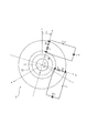
このことは、特許文献1の図2および図9によく示されている。これらの図は、電機子電圧をd軸電圧Vdとq軸電圧Vqとの直交2成分に分けて表示したものである。VdとVqとの全ベクトル和が電機子における総電圧に相当する。同図中に示される円はリンク電圧を表しており、電機子電圧の上限を規定するものである。そのため、電機子電圧ベクトルの先端が、リンク電圧円の内部に存在している場合に限り、同図の表示に従って所望の電機子電圧が発生され、逆に、電機子電圧ベクトルの先端がリンク電圧円の外部に出ると、所望の電圧は発生されず、トルク発生のための所望のq軸電流Iqを流すことができない(いわゆる、電圧飽和)。
This is well illustrated in FIGS. 2 and 9 of
さて、各図において逆起電力Eは+q軸方向のベクトルであり、具体的には、同期型ACサーボモータにおいてよく知られている式、E=ω・Φ、で表される。ここで、ωはモータの回転角速度、Φは電機子巻線に鎖交する総磁束であり、以下、特に断らない限り、ω≧0、Φ≧0、との仮定の下で説明する。このように、逆起電力Eはωに比例するから、高速回転時ほど大きい。同図9において、逆起電力ベクトルEが大きくなると、このベクトルの先端がリンク電圧円の円周に近づくことになるので、大きなIqを流すことができなくなる。なぜなら、Iqを大きくすると、同図中R・Iqとして表示される+q軸方向(Eと同方向)の駆動電圧ベクトルが長くなり、結果として、電機子電圧ベクトルの先端がリンク電圧円外に出てしまい、電圧飽和が生じてしまうからである。 In each figure, the back electromotive force E is a vector in the + q-axis direction, and is specifically expressed by an equation well-known in a synchronous AC servomotor, E = ω · Φ. Here, ω is the rotational angular velocity of the motor, and Φ is the total magnetic flux interlinked with the armature winding, and will be described below under the assumption that ω ≧ 0 and Φ ≧ 0 unless otherwise specified. Thus, since the back electromotive force E is proportional to ω, it is larger at high speed rotation. In FIG. 9, when the back electromotive force vector E increases, the tip of this vector approaches the circumference of the link voltage circle, so that a large Iq cannot be passed. This is because if Iq is increased, the driving voltage vector in the + q axis direction (same direction as E) displayed as R · Iq in the figure becomes longer, and as a result, the tip of the armature voltage vector goes out of the link voltage circle. This is because voltage saturation occurs.
しかし、ここで、同図2のように、無効電流Id(≦0)を流すことにすれば、不都合は解消する。Idを流すことによって、逆起電力ベクトルEと逆向きの相殺電圧ベクトル−ω・L・|Id|(−q軸方向)を発生できるからである。この−q軸方向の相殺電圧ベクトルが付加されることによって、+q軸方向の前記駆動電圧ベクトルR・Iqを長くしても、これらのベクトル和としての電機子電圧ベクトルの先端をリンク電圧円内に留めることが可能になる。したがって、この方法によれば、高速回転時であっても、大きなIqを流し続けることができ、安定して大きなトルク(∝Iq)を発生できる。 However, if the reactive current Id (≦ 0) is allowed to flow as shown in FIG. This is because by flowing Id, a counter voltage vector −ω · L · | Id | (−q axis direction) opposite to the counter electromotive force vector E can be generated. By adding the canceling voltage vector in the −q axis direction, even if the driving voltage vector R · Iq in the + q axis direction is lengthened, the tip of the armature voltage vector as the vector sum is placed in the link voltage circle. It becomes possible to stay on. Therefore, according to this method, a large Iq can continue to flow even during high-speed rotation, and a large torque (∝Iq) can be stably generated.
ところで、特許文献1では、逆起電力Eがモータの回転角速度ωに比例することに鑑み、無効電流Idをωのみの1変数関数として定義し、ωが大きくなるほど負方向に大きな無効電流Idを流して電圧飽和の発生を防止することとしている。ここでは、ωが決まるとIdが一意的に決まるので、無効電流Idの値はモータで発生させるトルクの大きさにはよらない。
したがって、高速回転時(ω:大)であれば、発生トルクの大きさによらず、常に負方向に大きな無効電流Idが流されていることになる。ところで、高速回転時であっても、モータにかかる負荷が小さいときは、発生トルクが小さくて済み、有効電流Iq(∝発生トルク)を小さくできる。すると、同図9において、駆動電圧ベクトルR・Iqを短くできるから、たとえ、逆起電力E=ω・Φが大きくても、また、無効電流Idに基づく相殺電圧ベクトル−ω・L・|Id|が小さくても、これらの合成ベクトルとしての電機子電圧ベクトルをリンク電圧円内に留めることが可能である。したがって、このとき負方向に大きな無効電流Idを流す必要はない。
しかし、特許文献1においては、このような場合も依然として負方向に大きな無効電流Idを流し続けている。このように無駄な電流を流し続けることは、本来発生させずにすんだはずの余分な熱を発生させ続けることになるので、モータの保守管理上追加的な補償措置を講ずる必要が生じたり、また、モータのエネルギー効率が悪化したり、といった、様々な問題が生じる。
By the way, in
Accordingly, during high-speed rotation (ω: large), a large reactive current Id always flows in the negative direction regardless of the magnitude of the generated torque. By the way, even during high-speed rotation, when the load on the motor is small, the generated torque can be small, and the effective current Iq (soot generation torque) can be reduced. Then, in FIG. 9, since the drive voltage vector R · Iq can be shortened, even if the back electromotive force E = ω · Φ is large, the cancellation voltage vector −ω · L · | Id based on the reactive current Id Even if | is small, it is possible to keep the armature voltage vector as a combined vector within the link voltage circle. Therefore, at this time, it is not necessary to flow a large reactive current Id in the negative direction.
However, in
本発明は、以上の問題に鑑みてなされたもので、モータにおける発生トルクに応じて無効電流Idの値を制御することによって、余分な熱の発生を抑え、かつ、効果的に電圧飽和の発生を防止できる電流制御方法、および、この電流制御方法を実施するための構成を備えるサーボモータを提供することを目的とする。 The present invention has been made in view of the above problems, and by controlling the value of the reactive current Id in accordance with the torque generated in the motor, the generation of excess heat is suppressed and voltage saturation is effectively generated. It is an object of the present invention to provide a current control method capable of preventing the above and a servo motor having a configuration for carrying out this current control method.
本発明の電流制御方法は、多相の電機子巻線を有する電機子と、界磁とを備え、前記各相の電機子巻線に電機子電流を流すことによって電機子磁束を発生させ、この電機子磁束と前記界磁による界磁束との間の相互作用に基づいて前記電機子と前記界磁とを相対回転運動させることにより回転動力を発生するサーボモータにおいて、電圧飽和が発生することを防止すべく、d軸方向を前記界磁束の方向とするdq変換を施した前記電機子に負のd軸電流Idを流す電流制御方法であって、前記電機子と前記界磁との相対回転速度が一定の条件下においては、前記d軸電流Idが、前記q軸電流の大きさ|Iq|に応じて負方向へ増加するように出力することを特徴とする。 The current control method of the present invention includes an armature having a multi-phase armature winding, and a field, and generates an armature magnetic flux by causing an armature current to flow through the armature winding of each phase, Voltage saturation occurs in a servo motor that generates rotational power by causing the armature and the field to rotate relative to each other based on the interaction between the armature flux and the field flux generated by the field. Is a current control method for causing a negative d-axis current Id to flow in the armature that has been subjected to dq conversion with the d-axis direction as the direction of the field magnetic flux. Under the condition that the rotation speed is constant, the d-axis current Id is outputted so as to increase in the negative direction according to the magnitude | Iq | of the q-axis current.
前記の通り、サーボモータにおける発生トルクTはq軸電流Iqに比例する。より具体的には、T∝Φ・Iq、で表される。ここで、Φは電機子巻線に鎖交する総磁束として前記したものと同一のものである。
さて、T∝Iqということは、絶対値の大きなトルクTを発生させようとすると、絶対値の大きなIqを流す必要があることを意味する。Iqの絶対値を大きくすると、駆動電圧ベクトルR・Iqが長くなるので、電機子電圧ベクトルをリンク電圧円内に留めるため、負方向に大きな無効電流Idを流すことによって、駆動電圧ベクトルR・Iqと逆向きの大きな相殺電圧ベクトル−ω・L・|Id|を生成させる必要がある。
逆に、低負荷時など、発生トルクTの絶対値が小さくてよいときは、絶対値の小さいIqで済み、駆動電圧ベクトルR・Iqを短くできるから、相殺電圧ベクトル−ω・L・|Id|を生成するための無効電流Idの負方向への大きさを小さくできる。
As described above, the generated torque T in the servo motor is proportional to the q-axis current Iq. More specifically, it is represented by T∝Φ · Iq. Here, Φ is the same as described above as the total magnetic flux interlinked with the armature winding.
Now, T∝Iq means that if a torque T having a large absolute value is to be generated, Iq having a large absolute value needs to flow. When the absolute value of Iq is increased, the drive voltage vector R · Iq becomes longer. Therefore, in order to keep the armature voltage vector within the link voltage circle, a large reactive current Id is caused to flow in the negative direction, thereby driving voltage vector R · Iq. It is necessary to generate a large canceling voltage vector -ω · L · | Id |
Conversely, when the absolute value of the generated torque T may be small, such as when the load is low, a small absolute value Iq is sufficient, and the drive voltage vector R · Iq can be shortened, so that the canceling voltage vector −ω · L · | Id The negative current Id for generating | can be reduced in the negative direction.
したがって、発生トルクの絶対値が大きく|Iq|が大きいときは、Idを負方向に大きくする必要があり、逆に、発生トルクの絶対値が小さく|Iq|が小さいときIdの負方向への大きさは小さくて済む。
本発明では、このようなIdと|Iq|との関係を実現するべく、電機子と界磁との相対回転速度が一定の条件下においては、Idが|Iq|に応じて負方向へ増加するようにしている。
この発明によれば、低負荷時など|Iq|が小さいときには、Idの負方向への大きさを小さく抑え、無駄な無効電流Idが流されるのを防止できる。そのため、無駄な無効電流Idに起因する余分な熱の発生を効果的に抑制できるから、モータ保守管理上の追加的な補償措置が不要になってモータの構成を簡素化できるとともに、モータを安価に製造でき、また、モータのエネルギー効率を向上させることができる。
Therefore, when the absolute value of the generated torque is large and | Iq | is large, it is necessary to increase Id in the negative direction. Conversely, when the absolute value of the generated torque is small and | Iq | The size is small.
In the present invention, in order to realize such a relationship between Id and | Iq |, Id increases in the negative direction according to | Iq | under the condition that the relative rotational speed between the armature and the field is constant. Like to do.
According to the present invention, when | Iq | is small, such as when the load is low, it is possible to suppress the magnitude of Id in the negative direction and prevent unnecessary reactive current Id from flowing. As a result, it is possible to effectively suppress the generation of excess heat due to the wasted reactive current Id, eliminating the need for additional compensation measures for motor maintenance management, simplifying the motor configuration, and reducing the motor cost. In addition, the energy efficiency of the motor can be improved.
本発明では、I2=Id2+Iq2、で表される前記電機子を流れる総電流Iの絶対値が、前記電機子における許容電流値Imaxを超えないように制限することが好ましい。 In the present invention, it is preferable to limit the absolute value of the total current I flowing through the armature represented by I 2 = Id 2 + Iq 2 so as not to exceed the allowable current value Imax in the armature.
電機子の総電流Iの絶対値|I|が所定の許容電流値Imaxを超えてしまうと、電機子に過度の負担がかかるため、異常な発熱が生じたり、最悪の場合、サーボモータが破損してしまったりするおそれがある。
本発明では、この問題を解決すべく、|I|がImaxを超えないように制限することとしている。したがって、常に、|I|≦Imax、の状態を維持できるから、電機子に過度の電流が流れるのを抑止でき、サーボモータの破損を防止できる。
If the absolute value | I | of the total current I of the armature exceeds a predetermined allowable current value Imax, an excessive load is applied to the armature, resulting in abnormal heat generation or, in the worst case, damage to the servo motor. There is a risk of doing so.
In the present invention, in order to solve this problem, | I | is limited so as not to exceed Imax. Therefore, since the state of | I | ≦ Imax can always be maintained, it is possible to prevent an excessive current from flowing through the armature and prevent the servo motor from being damaged.
また、本発明では、前記Idと前記Iqとは、前記電機子を流れる総電流I、および、0°≦θ<90°を満たす位相角θに対して、Id=−|I|・sinθ、Iq=I・cosθ、の関係を満足するように規定され、前記位相角θは、前記電機子と前記界磁との相対回転の速さについての増加関数として規定されることが好ましい。 Further, in the present invention, the Id and the Iq are expressed as Id = − | I | · sin θ, with respect to the total current I flowing through the armature and the phase angle θ satisfying 0 ° ≦ θ <90 °. It is preferable that the relationship of Iq = I · cos θ is satisfied, and the phase angle θ is specified as an increasing function with respect to the speed of relative rotation between the armature and the field.
電機子と界磁との相対回転の速さωが大きくなると、電機子に絶対値の大きな逆起電力ω・Φが生じるが、それと同時に、本発明では、速さωについての増加関数θが大きくなって、無効電流Id(=−|I|・sinθ)が負方向へ大きくなる。前記の通り、負方向へ大きな無効電流Idは、逆起電力ベクトルω・Φと逆向きの大きな相殺電圧ベクトル−ω・L・|Id|を生成し、大きな逆起電力を相殺する。したがって、電圧飽和の発生を防止でき、サーボモータにおけるサーボ制御を適切に行うことができる。 When the relative rotation speed ω between the armature and the field increases, a large back electromotive force ω · Φ is generated in the armature. At the same time, in the present invention, the increasing function θ with respect to the speed ω is As the value increases, the reactive current Id (= − | I | · sin θ) increases in the negative direction. As described above, the reactive current Id that is large in the negative direction generates a large canceling voltage vector -ω · L · | Id | that is opposite to the counter electromotive force vector ω · Φ, and cancels the large counter electromotive force. Therefore, occurrence of voltage saturation can be prevented, and servo control in the servo motor can be appropriately performed.
なお、相対回転速度ωが一定の条件下においては、前記のようにIdが|Iq|に応じて負方向へ増加するように、θの関数形が決定されているものとする。
簡単な例として、θがωのみの関数であるとすれば、ωが一定のときはθが一意的に決定され、Id=−|I|・sinθ、|Iq|=|I|・cosθ、は共に|I|のみの関数となるので、|Iq|を増大させるために|I|を増大させれば、それに応じてIdが負方向へ増加され、結果的に、Idが|Iq|に応じて負方向へ増加するように構成されることになる。
また、別の例として、θがωのみならずIq(∝トルクT)の関数θ(ω、Iq)として構成されるときは、ωを一定にしてもθはIqの関数として変化される。このときは、ω一定の下、Idが|Iq|に応じて負方向へ増加するように、Iqに対するθ(ω、Iq)の関数形が調整されることになる。
It is assumed that the function form of θ is determined so that Id increases in the negative direction according to | Iq | as described above under the condition where the relative rotational speed ω is constant.
As a simple example, if θ is a function of only ω, θ is uniquely determined when ω is constant, and Id = − | I | · sinθ, | Iq | = | I | · cosθ, Are both functions only of | I |, so if | I | is increased to increase | Iq |, Id is increased in the negative direction accordingly, and as a result, Id becomes | Iq | Accordingly, it is configured to increase in the negative direction.
As another example, when θ is configured not only as ω but also as a function θ (ω, Iq) of Iq (∝ torque T), θ is changed as a function of Iq even if ω is constant. At this time, the function form of θ (ω, Iq) with respect to Iq is adjusted so that Id increases in the negative direction according to | Iq |
また、本発明では、前記Idと前記Iqとは、0°≦θ<90°を満たす位相角θに対して、Id=−|Iq|・tanθの関係を満足するように規定され、前記位相角θは、前記電機子と前記界磁との相対回転の速さについての増加関数として規定される構成を採用してもよい。 In the present invention, the Id and the Iq are defined to satisfy the relationship of Id = − | Iq | · tan θ with respect to the phase angle θ satisfying 0 ° ≦ θ <90 °, and the phase The angle θ may adopt a configuration defined as an increasing function with respect to the speed of relative rotation between the armature and the field.
この構成においても、相対回転の速さωが大きくなると、θが大きくなり、無効電流Id(=−|Iq|・tanθ)が負方向へ大きくなるから、大きな相殺電圧ベクトルが生成される。したがって、速さωが大きくなって大きな逆起電力が生じても、これを相殺でき、電圧飽和の発生を効果的に防止できる。 Also in this configuration, as the relative rotation speed ω increases, θ increases and the reactive current Id (= − | Iq | · tan θ) increases in the negative direction, so that a large canceling voltage vector is generated. Therefore, even if the speed ω is increased and a large back electromotive force is generated, this can be canceled out and the occurrence of voltage saturation can be effectively prevented.
なお、相対回転速度ωが一定の条件下においては、Idが|Iq|に応じて負方向へ増加するように、θの関数形が決定されているものとする。このとき、θはωのみの1変数関数でも、ωおよびIqの2変数関数でも、または、それ以上の多変数関数でもよい。特に、θがωのみの1変数関数のときは、ωが一定の条件下ではθが一定であり、Id=−|Iq|・tanθ、は自動的に|Iq|に応じて負方向へ増加する。 It is assumed that the function form of θ is determined so that Id increases in the negative direction according to | Iq | under the condition that the relative rotational speed ω is constant. At this time, θ may be a one-variable function with only ω, a two-variable function with ω and Iq, or a multivariable function with more than that. In particular, when θ is a univariate function with only ω, θ is constant under the condition that ω is constant, and Id = − | Iq | · tanθ is automatically increased in the negative direction according to | Iq | To do.
続いて、以上の電流制御方法を実現するための構成を備える本発明のサーボモータについて説明する。 Next, the servo motor of the present invention having a configuration for realizing the above current control method will be described.
本発明のサーボモータは、多相の電機子巻線を有する電機子と、界磁とを備え、前記各相の電機子巻線に電機子電流を流すことによって電機子磁束を発生させ、この電機子磁束と前記界磁による界磁束との間の相互作用に基づいて前記電機子と前記界磁とを相対回転運動させることにより回転動力を発生するサーボモータにおいて、d軸方向を前記界磁束の方向とするdq変換を施した前記電機子に対する電流指令として、トルクを発生させるためのq軸電流指令Iq*と、電圧飽和の発生を防止するための負のd軸電流指令Id*とを出力する電流指令器を備え、前記電機子と前記界磁との相対回転速度が一定の条件下においては、前記d軸電流指令Id*が、前記q軸電流指令の大きさ|Iq*|に応じて負方向へ増加するように出力されることを特徴とする。 The servo motor of the present invention includes an armature having a multi-phase armature winding and a field, and generates an armature magnetic flux by passing an armature current through the armature winding of each phase. In a servo motor that generates rotational power by relatively rotating the armature and the field based on the interaction between the armature flux and the field flux by the field, the d-axis direction is defined as the field flux. As a current command for the armature subjected to the dq conversion in the direction of q, a q-axis current command Iq * for generating torque and a negative d-axis current command Id * for preventing the occurrence of voltage saturation An output current command device, and under the condition that the relative rotational speed between the armature and the field is constant, the d-axis current command Id * becomes the magnitude | Iq * | of the q-axis current command. As a result, the output increases in the negative direction. Is the fact characterized.
電機子と界磁との相対回転速度ωが一定の条件下においては、Id*が|Iq*|に応じて負方向へ増加するように出力されるので、低負荷時など、|Iq*|(∝|T*|:但し、T*はトルク指令)が小さいときには、Id*の負方向への大きさも小さくなっており、無駄な無効電流Idが電機子に流されるのを的確に防止できる。そのため、無駄な無効電流Idに起因する余分な熱の発生を効果的に抑制できるから、モータ保守管理上の追加的な補償措置が不要になってサーボモータの構成を簡素化できるとともに、サーボモータを安価に製造でき、また、サーボモータのエネルギー効率を向上させることができる。 Under the condition that the relative rotational speed ω between the armature and the field is constant, Id * is output so as to increase in the negative direction according to | Iq * |. Therefore, when the load is low, | Iq * | When (∝ | T * |: where T * is a torque command) is small, the magnitude of Id * in the negative direction is also small, and it is possible to accurately prevent unnecessary reactive current Id from flowing through the armature. . Therefore, it is possible to effectively suppress the generation of excess heat due to the wasted reactive current Id, so that no additional compensation measures for motor maintenance management are required, the servo motor configuration can be simplified, and the servo motor Can be manufactured at low cost, and the energy efficiency of the servo motor can be improved.
本発明では、前記電流指令器は、前記電機子の総電流指令I*を出力する総電流指令器と、I*2=Id*2+Iq*2、の関係を満足するように、前記I*から前記Id*および前記Iq*を演算し出力するdq電流指令器とを備え、前記総電流指令器は、前記I*の絶対値が、前記電機子における許容電流値Imaxを超えないように制限するリミッタを備えて構成されることが好ましい。 In the present invention, the current command device satisfies the relationship of I * 2 = Id * 2 + Iq * 2 and the total current command device that outputs the total current command I * of the armature . A dq current command device that calculates and outputs the Id * and Iq * from the total current command device so that the absolute value of the I * does not exceed the allowable current value Imax in the armature. It is preferable that a limiter is provided.
この構成によれば、リミッタによって、電機子の総電流指令I*の絶対値|I*|が、常に、電機子における許容電流値Imax以下に制限されるので、この電流指令I*に基づいて電機子に流される総電流Iの絶対値|I|がImaxを超えることがなくなる。そのため、電機子に過度の電流が流れるのを的確に抑止でき、サーボモータの破損を防止できる。 According to this configuration, since the absolute value | I * | of the total current command I * of the armature is always limited to the allowable current value Imax or less in the armature by the limiter, based on the current command I *. The absolute value | I | of the total current I flowing through the armature does not exceed Imax. Therefore, excessive current can be prevented from flowing through the armature and the servo motor can be prevented from being damaged.
また、本発明では、前記相対回転運動の速さを測定する速度センサが設けられ、前記電流指令器は、前記電機子の総電流指令I*を出力する総電流指令器と、前記速度センサで測定された速さから、この速さについての増加関数として、0°≦θ<90°を満たす位相角θを演算し、Id*=−|I*|・sinθ、Iq*=I*・cosθ、の関係を満足するように、前記I*から前記Id*および前記Iq*を演算して出力するdq電流指令器とを備えて構成されることが好ましい。 In the present invention, a speed sensor that measures the speed of the relative rotational motion is provided, and the current command device includes a total current command device that outputs a total current command I * of the armature, and the speed sensor. From the measured speed, a phase angle θ satisfying 0 ° ≦ θ <90 ° is calculated as an increasing function for this speed, and Id * = − | I * | · sinθ, Iq * = I * · cosθ , of so as to satisfy the relationship, be configured and a dq current command for outputting from the I * the Id * and the Iq * and calculates are preferred.
この構成において、dq電流指令器は、速度センサで測定された回転速さωから位相角θを演算し、このθと、総電流指令器から入力される総電流指令I*とに基づいて、Id*とIq*とを演算する。
速さωが大きくなると、電機子に大きな逆起電力ω・Φが生じるが、それと同時に、本発明では、速さωについての増加関数としてのθが大きくなって、無効電流指令Id*(=−|I*|・sinθ)が負方向へ大きくなる。この無効電流指令Id*に基づいて電機子に流される負方向へ大きな無効電流Idは、前記の通り、逆起電力ベクトルω・Φと逆向きの大きな相殺電圧ベクトル−ω・L・|Id|を生成し、大きな逆起電力を相殺する。したがって、本発明によれば、電圧飽和の発生を防止でき、サーボモータにおけるサーボ制御を適切に行うことができる。
In this configuration, the dq current command device calculates the phase angle θ from the rotational speed ω measured by the speed sensor, and based on this θ and the total current command I * input from the total current command device, Id * and Iq * are calculated.
When the speed ω is increased, a large counter electromotive force ω · Φ is generated in the armature. At the same time, in the present invention, θ as an increasing function with respect to the speed ω is increased, and the reactive current command Id * (= − | I * | · sin θ) increases in the negative direction. As described above, the large negative reactive current Id flowing in the armature based on the reactive current command Id * is a large canceling voltage vector −ω · L · | Id | that is opposite to the counter electromotive force vector ω · Φ. To cancel out the large back electromotive force. Therefore, according to the present invention, the occurrence of voltage saturation can be prevented, and servo control in the servo motor can be appropriately performed.
また、本発明では、前記相対回転運動の速さを測定する速度センサが設けられ、前記電流指令器は、暫定電流指令I*を出力する暫定電流指令器と、前記速度センサで測定された速さから、この速さについての増加関数として、0°≦θ<90°を満たす位相角θを演算し、前記I*に対して、Id*=−|I*|・tanθ、Iq*=I*、の関係を満足する前記Id*、前記Iq*を演算して出力するdq電流指令器とを備えて構成されていてもよい。 In the present invention, a speed sensor for measuring the speed of the relative rotational motion is provided, and the current command device includes a temporary current command device that outputs a temporary current command I * and a speed measured by the speed sensor. Then, as an increasing function for this speed, a phase angle θ satisfying 0 ° ≦ θ <90 ° is calculated, and Id * = − | I * | · tanθ, Iq * = I with respect to I * . The dq current command device that calculates and outputs the Id * and Iq * satisfying the relationship of * and may be configured.
この構成においても、回転速さωが大きくなると、ωの増加関数としてのθが大きくなり、無効電流指令Id*(=−|I*|・tanθ)が負方向へ大きくなるから、これに基づいて電機子に流される無効電流Idによって逆起電力と逆向きの大きな相殺電圧ベクトルが生成される。したがって、速さωが大きくなって大きな逆起電力が生じても、これを相殺でき、電圧飽和の発生を防止できる。 Also in this configuration, as the rotational speed ω increases, θ as an increasing function of ω increases, and the reactive current command Id * (= − | I * | · tan θ) increases in the negative direction. Thus, a large canceling voltage vector opposite to the counter electromotive force is generated by the reactive current Id flowing through the armature. Therefore, even if the speed ω is increased and a large counter electromotive force is generated, this can be canceled out and the occurrence of voltage saturation can be prevented.
また、前記電流指令器は、Is*2=Id*2+Iq*2=I*2・(1+tan2θ)、で表される前記電機子の総電流指令Is*の絶対値が、前記電機子における許容電流値Imaxを超えないように制限するリミッタを備えて構成されることが好ましい。 Further, the current command device has an absolute value of the total current command Is * of the armature represented by Is * 2 = Id * 2 + Iq * 2 = I * 2 · (1 + tan 2 θ) It is preferable to provide a limiter that limits the allowable current value Imax in the range so as not to exceed.
この構成によれば、リミッタによって、電機子の総電流指令の絶対値|Is*|が、常に、電機子における許容電流値Imax以下に制限されるので、この総電流指令Is*に基づいて電機子に流される総電流Is(但し、Is2=Id2+Iq2)の絶対値|Is|がImaxを超えることがなくなる。そのため、電機子に過度の電流が流れるのを的確に抑止でき、サーボモータの破損を防止できる。 According to this arrangement, the limiter, the absolute value of the total current command armature | Is * | is always with because they are limited to less than the allowable current value Imax in the armature, based on the total current command Is * Electric The absolute value | Is | of the total current Is (provided Is 2 = Id 2 + Iq 2 ) flowing through the child does not exceed Imax. Therefore, excessive current can be prevented from flowing through the armature and the servo motor can be prevented from being damaged.
以下、本発明の実施形態を図面に基づいて説明する。
<第1実施形態>
図1は、本発明の第1実施形態にかかるサーボモータ1の等価回路図である。
サーボモータ1は、永久磁石によって構成される界磁11と、3相(u、v、w相)の電機子巻線を有する電機子12とを備える3相同期モータである。界磁11は、ロータとして回転可能に設けられている。ステータとしての電機子12の各相に、互いに位相が120°ずつ異なる交流電流(電機子電流)を流すと、この交流電流と同一の周波数で回転する電機子磁束を発生できる。界磁11は、この回転電機子磁束に対して自身の界磁束を平行にしようとする磁気的な力を受けるので、回転電機子磁束に追従して回転される(回転角度ψ、回転角速度ω=dψ/dt。以下、特に断らない限りω≧0、と仮定する)。このようにして、サーボモータ1において回転動力が発生される。
なお、図1において、Vu、Vv、Vwは電機子12各相の電機子電圧、Rは各相共通の抵抗値、L´は各相共通の自己インダクタンス、M´は各相間の相互インダクタンスである。また、界磁11の回転角度ψは、界磁束の方向(界磁11のN極とS極とを結ぶ方向)が、電機子12のu相の形成方向に対してなす角度として定義される。
Hereinafter, embodiments of the present invention will be described with reference to the drawings.
<First Embodiment>
FIG. 1 is an equivalent circuit diagram of the
The
In FIG. 1, Vu, Vv, and Vw are armature voltages of each phase of the
図1のサーボモータ1に対してdq変換を施すと、図2の等価回路が得られる。
図2において、d軸は界磁束の方向と一致され、これと直交する方向にq軸が形成される。図1における3相(u、v、w相)の電機子巻線は、d相とq相とからなる2相の電機子巻線に変換されている。
この図において、Vd、Vqは各相の電機子電圧、Id、Iqは各相の電機子電流、Rは各相共通の抵抗値、Lは各相共通の自己インダクタンス、Φは各相電機子巻線に鎖交する総磁束である。これらの各量は、同期モータに関して一般に知られている以下の数1に表される回路方程式を満たす。
When dq conversion is performed on the
In FIG. 2, the d-axis is coincident with the direction of the field magnetic flux, and the q-axis is formed in a direction orthogonal thereto. The three-phase (u, v, w-phase) armature winding in FIG. 1 is converted into a two-phase armature winding consisting of a d-phase and a q-phase.
In this figure, Vd and Vq are armature voltages of each phase, Id and Iq are armature currents of each phase, R is a resistance value common to each phase, L is a self-inductance common to each phase, and Φ is an armature of each phase This is the total magnetic flux interlinking with the winding. Each of these quantities satisfies the circuit equation expressed by the following

ここで、Pは微分演算子d/dtである。この式の右辺の第2項は、dq各相の巻線に誘起される逆起電力を示している。したがって、Φによる逆起電力ω・Φは、q相巻線のみに誘起されることがわかる。 Here, P is a differential operator d / dt. The second term on the right side of this equation indicates the counter electromotive force induced in the winding of each phase of dq. Therefore, it can be seen that the counter electromotive force ω · Φ due to Φ is induced only in the q-phase winding.
図2において、サーボモータ1の回転トルクTを発生させるのは、d軸方向の界磁束と直交するq軸電流Iqである。具体的には、T∝Φ・Iq、である。これに対してd軸電流Idは、トルクTの発生に関与しない無効電流である。しかし、特許文献1に開示されているように、負の無効電流Idを流すと、逆起電力を相殺する相殺電圧成分を発生でき、サーボモータ1における電圧飽和の発生を防止できる。
In FIG. 2, the rotation torque T of the
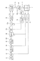
図3は、図1および図2に示すサーボモータ1におけるフィードバック制御ブロック線図である。
位置指令器21は、所定のパートプログラム等に従ってサーボモータ1の回転角度(界磁11の回転角度ψ)の指令値ψ*を出力する。角度指令ψ*は、位置比較器22において、位置センサ31で測定された実際の回転角度ψと比較され、両者の角度偏差Δψ=ψ*―ψが位置制御器23に入力される。速度指令器としての位置制御器23は、Δψに基づいて所定の演算を行い、サーボモータ1の回転速度の指令値ω*を算出し、出力する。速度指令ω*は、速度比較器24において、速度センサ32で測定された実際の回転速度ωと比較され、両者の速度偏差Δω=ω*―ωが速度制御器25に入力される。本発明の総電流指令器としての速度制御器25は、Δωに基づいて所定の演算を行い、サーボモータ1の電機子12における総電流の指令値I*を算出し、出力する。総電流指令I*は、そのまま、演算器26に入力される。なお、速度制御器25は、リミッタ251を備えて構成されている。後で詳しく述べるように、リミッタ251は予め設定された総電流指令の上限値I*maxに基づいて総電流指令I*を監視し、総電流指令の絶対値|I*|がI*maxを上回らないように制限する役割を果たす。
FIG. 3 is a feedback control block diagram in the
The
さて、演算器26は、速度センサ32で測定された速さωに基づいてdq電流位相角θを算出する。ここで、θは、ωについての1変数関数θ(ω)として定義されており、演算器26には、このθの関数形が予め記憶されているものとする。演算器26は、速度センサ32から入力されたωを関数θ(ω)に代入し、その演算結果をdq電流位相角度として算出する。なお、後で詳しく述べるように、関数θ(ω)は、速さωについては増加関数として変化される。また、0°≦θ(ω)<90°、である。
The
本発明のdq電流指令器としての演算器26は、以上のように算出された位相角θと、速度制御器25から入力された総電流指令I*とに基づいて、Id*=−|I*|・sinθ、Iq*=I*・cosθ、で表されるd軸電流指令Id*とq軸電流指令Iq*とを演算し、出力する。I*、Id*、Iq*の間にはI*2=Id*2+Iq*2、の関係式が成立している。
なお、速度制御器25および演算器26は、速度偏差Δωから電機子12の電流指令を演算して出力する、本発明の電流指令器を構成している。
The
The speed controller 25 and the
dq各軸電流指令Id*、Iq*は、それぞれ、dq各軸電流比較器27d、27qにおいて、サーボモータ1における実際のdq各軸電流Id、Iqと比較され、dq各軸電流偏差ΔId=Id*―Id、ΔIq=Iq*―Iqが電流制御器28に入力される。ここで、電流比較器27d、27qに入力されるdq各軸電流Id、Iqは、3相サーボモータ1(dq変換前:図1参照)の各相の電流Iu、Iv、Iwを各相ごとの電流センサ33u、33v、33wによって測定し、これらを3相/2相変換器34で2相のdq軸電流Id、Iqに変換することによって得られたものである。
The dq axis current commands Id * and Iq * are compared with the actual dq axis currents Id and Iq in the
さて、dq各軸電流偏差ΔId、ΔIqが入力された電流制御器28は、これらに基づいて所定の演算を行い、dq各軸電圧Vd、Vqを算出して、出力する。
2相/3相変換器29は、このVd、Vqの入力を基に演算を行い、算出された3相電圧Vu、Vv、Vwを電力変換器30に出力する。
電力変換器30は、図示しない電源装置を介して、3相電圧Vu、Vv、Vwに対応する3相電流Iu、Iv、Iwを出力し、サーボモータ1の電機子12のu、v、wの各相に流す。
The current controller 28 to which the dq axis current deviations ΔId and ΔIq are input performs a predetermined calculation based on them, and calculates and outputs the dq axis voltages Vd and Vq.
The two-phase / three-
The
サーボモータ1は、以上の構成を備えるフィードバックループによって、その位置、速度、電流が、適切に制御されるようになっている。なお、速度センサ32で回転速度ωを検出する代わりに、位置センサ31における検出位置ψのサンプリング周期ごとの差分を用いて回転速度ωを算出してもよい。
The position, speed, and current of the
続いて、図4を用いて、本実施形態における電流制御方法について詳しく説明する。なお、以下の電流制御方法を具体的に実現するのは、主として、図3における速度制御器25、演算器26である。
Next, the current control method in the present embodiment will be described in detail with reference to FIG. The following current control method is specifically realized mainly by the speed controller 25 and the
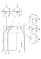
図4は、速度制御器25から出力される総電流指令I*を一定とした場合における、q軸電流指令Iq*および位相角θの、モータ回転速度ωに対する変化の様子を示した図である。ここで、I*を一定とする仮定は、図3において、速度偏差Δωを一定とする仮定と同等である。実際のサーボ制御状態ではΔωは時々刻々と変動するので、このような仮定が成り立つのは非常に稀な場合に限られることに注意すべきである。したがって、以上の仮定は、あくまで説明の簡素化のために便宜上設定されるものにすぎない。なお、図4では、本実施形態の効果をよりよく示すために、I*≧0、ω≧0、の場合を示す。 FIG. 4 is a diagram showing how the q-axis current command Iq * and the phase angle θ change with respect to the motor rotation speed ω when the total current command I * output from the speed controller 25 is constant. . Here, the assumption that I * is constant is equivalent to the assumption that the speed deviation Δω is constant in FIG. 3. It should be noted that in the actual servo control state, Δω fluctuates from moment to moment, and this assumption is valid only in very rare cases. Therefore, the above assumptions are merely set for convenience in order to simplify the description. FIG. 4 shows a case where I * ≧ 0 and ω ≧ 0 in order to better illustrate the effect of this embodiment.
図4(A)は、縦軸をIq*、横軸を回転速度ωとして表したグラフである。前記の通り、Iq*はモータのトルク指令T*と比例関係(T*∝Φ・Iq*)にあるので、縦軸をトルク指令T*と見ることもできる。図4(A)に示される各曲線C1、C2は、互いに異なる総電流指令I1 *、I2 *(I1 *>I2 *)について表されたものである。 FIG. 4A is a graph in which the vertical axis represents Iq * and the horizontal axis represents the rotational speed ω. As described above, since Iq * is proportional to the motor torque command T * (T * ∝Φ · Iq * ), the vertical axis can also be regarded as the torque command T * . Each of the curves C 1 and C 2 shown in FIG. 4A is expressed with respect to different total current commands I 1 * and I 2 * (I 1 * > I 2 * ).
図4(B)は、縦軸を位相角θ、横軸を回転速度ωとして表した図である。この図は、演算器26に予め記憶されているθの関数形θ(ω)を表すものと見ることができる。
0≦ω≦ωi、の範囲では、θ(ω)=0である。d軸電流制御開始速度ωiは、無効電流Idを流し始める時点の回転速度であり、電圧飽和を効果的に抑制する観点から最適な値が予め設定されているものとする。
ωi≦ω≦ωf、の範囲では、θ(ω)は直線的に増加する。ω=ωfのときのθ(ω)をθfとすると、具体的な表式は、θ(ω)=θf+θf・(ω−ωf)/(ωf−ωi)、である。図4(Bi)、(Ba)、(Bf)は、それぞれ、ω=ωi、ωa(任意の値)、ωfのときの、I*(I1 *またはI2 *)、Id*、Iq*の関係を示すベクトル図である。これらの各図において、位相角θはθi(=0)、θa、θf、として表示されている。
以上のように、位相角θ(ω)は、0≦ω≦ωf、の領域内において、回転速度(速さ)ωについての増加関数として規定されていることがわかる。
FIG. 4B is a diagram in which the vertical axis represents the phase angle θ and the horizontal axis represents the rotational speed ω. This figure can be regarded as representing a function form θ (ω) of θ stored in advance in the
In the range of 0 ≦ ω ≦ ωi, θ (ω) = 0. The d-axis current control start speed ωi is a rotation speed at the time when the reactive current Id starts to flow, and is set to an optimal value in advance from the viewpoint of effectively suppressing voltage saturation.
In the range of ωi ≦ ω ≦ ωf, θ (ω) increases linearly. When θ (ω) when ω = ωf is θf, a specific expression is θ (ω) = θf + θf · (ω−ωf) / (ωf−ωi). 4 (Bi), (Ba), and (Bf) show I * (I 1 * or I 2 * ), Id * , Iq * when ω = ωi, ωa (arbitrary value), and ωf, respectively . It is a vector diagram which shows the relationship. In each of these drawings, the phase angle θ is displayed as θi (= 0), θa, and θf.
As described above, it can be seen that the phase angle θ (ω) is defined as an increasing function with respect to the rotational speed (speed) ω in the region of 0 ≦ ω ≦ ωf.
回転速度ωを0から徐々に増やしていく場合を考える。0≦ω≦ωi、の範囲では、θ=0であるから、Id*=−|I*|・sinθ=0、Iq*=I*・cosθ=I*、である。従って、演算器26から出力される電流指令はq軸方向のみであり、このとき、サーボモータ1に無効電流Idは流されていないことになる。これは、回転速度ωが小さい領域であれば、前記数1における逆起電力ω・Φが小さいので、無効電流Idを流さなくとも電圧飽和が起こらないからである。
Consider a case where the rotational speed ω is gradually increased from zero. In the range of 0 ≦ ω ≦ ωi, θ = 0, so Id * = − | I * | · sin θ = 0 and Iq * = I * · cos θ = I * . Therefore, the current command output from the
ωが大きくなっていき、ωi≦ω≦ωf、の範囲内に入ると、θ(ω)≠0(>0)となり、d軸電流制御が行われる。すなわち、Id*=−|I*|・sinθ=−I*・sinθ、Iq*=I*・cosθ、を満たすdq各軸電流指令に基づいて、dq各軸電流Id、Iqが電機子12に流されるようになる。無効電流Idは、前記の相殺電圧ベクトル−ω・L・|Id|を生成し、逆起電力ベクトルω・Φを相殺して、電圧飽和の発生を防止する。特に、位相角θが回転速度ωについての増加関数として規定されているので、ωが大きくなると無効電流指令Id*(=−|I*|・sinθ)が負方向へ大きくなり、負方向へ大きな無効電流Idが流される。ωが大きいときは逆起電力ベクトルが大きくなっているが、それと同時に、負方向へ大きな無効電流Idに基づく大きな相殺電圧ベクトルが生成されていることになるので、電圧飽和の発生が効果的に防止される。
As ω increases and enters the range of ωi ≦ ω ≦ ωf, θ (ω) ≠ 0 (> 0) and d-axis current control is performed. That is, the dq axis currents Id and Iq are supplied to the
続いて、回転速度ωを、ωi≦ω≦ωf、内の任意の一つの値ωaに固定した条件下でのdq各軸電流指令Id*、Iq*について説明する。ωがωaに固定されているので、ωの1変数関数としての位相角θは一義的に決まっており、前記条件下では一定の値θaを有する。
図4(C1)は、I*=I1 *(曲線C1)、ω=ωaのときの、dq各軸電流指令Id1 *とIq1 *とを示す図、図4(C2)は、I*=I2 *(曲線C2)、ω=ωaのときの、dq各軸電流指令Id2 *とIq2 *とを示す図である。ここで、Idi *=−|Ii *|・sinθ=−Ii *・sinθ<0:−d軸方向、である(i=1、2)。
図4(C1)、(C2)において、回転速度はωaで共通だから、位相角θaも共通である。そのため、Idi *(=−Ii *・sinθa)、|Iqi *|(=Ii *・cosθa)は、総電流指令Ii *によって決定される。ここで、I1 *>I2 *だから、−Id1 *>−Id2 *、かつ、|Iq1 *|>|Iq2 *|、である。したがって、回転速度ωが一定(=ωa)の条件下においては、Id*が|Iq*|に応じて負方向へ増加していることがわかる。このことは、前記の各式から得られる、Id*=−|Iq*|・tanθa、という表式からも容易に理解される(∵θa=一定)。
Next, the dq axis current commands Id * and Iq * under the condition that the rotational speed ω is fixed to any one value ωa within ωi ≦ ω ≦ ωf will be described. Since ω is fixed at ωa, the phase angle θ as a univariate function of ω is uniquely determined, and has a constant value θa under the above conditions.
FIG. 4 (C1) is a diagram showing dq axis current commands Id 1 * and Iq 1 * when I * = I 1 * (curve C 1 ) and ω = ωa, and FIG. I * = I 2 * (curve C 2), is a diagram illustrating the, and Iq 2 * and the dq axes current command Id 2 * when omega = .omega.a. Here, Id i * = − | I i * | · sin θ = −I i * · sin θ <0: −d axis direction (i = 1, 2).
4 (C1) and 4 (C2), since the rotation speed is common to ωa, the phase angle θa is also common. Therefore, Id i * (= − I i * · sin θa) and | Iq i * | (= I i * · cos θa) are determined by the total current command I i * . Here, since I 1 * > I 2 * , −Id 1 * > − Id 2 * and | Iq 1 * |> | Iq 2 * |. Therefore, it can be seen that Id * increases in the negative direction according to | Iq * | under the condition that the rotational speed ω is constant (= ωa). This can be easily understood from the expression “Id * = − | Iq * | · tan θa” obtained from the above-described expressions (∵θa = constant).
前に詳しく述べたように、低負荷時などIq(∝T)が小さいときには、前記駆動電圧ベクトルR・Iqが小さいから、電圧飽和を防止するために負方向に大きな無効電流Idを流す必要はない。本実施形態では、Id*が|Iq*|に応じて負方向へ増加する(ω一定の条件下)ので、|Iq*|が小さいときにはId*の負方向への大きさを小さくでき、無駄な無効電流Idが流されるのを防止できる。そのため、無駄な無効電流Idに起因する余分な熱の発生を効果的に抑制できるから、サーボモータ1保守管理上の追加的な補償措置が不要になってサーボモータ1の構成を簡素化できるとともに、サーボモータ1を安価に製造でき、また、サーボモータ1のエネルギー効率を向上させることができる。
なお、図4においては、I*≧0、ω≧0、として説明をしたが、以上の説明は、図4とはモータ1の回転状態が正反対の場合、すなわち、I*≦0、ω≦0の場合にほとんどそのまま適用できる。
As described in detail above, when Iq (∝T) is small, such as when the load is low, the driving voltage vector R · Iq is small. Therefore, it is necessary to flow a large reactive current Id in the negative direction in order to prevent voltage saturation. Absent. In this embodiment, Id * increases in the negative direction according to | Iq * | (under constant ω). Therefore, when | Iq * | is small, the magnitude of Id * in the negative direction can be reduced, which is useless. It is possible to prevent a reactive current Id from flowing. As a result, it is possible to effectively suppress the generation of excess heat due to the wasted reactive current Id, so that an additional compensation measure in the maintenance and management of the
In FIG. 4, I * ≧ 0 and ω ≧ 0 have been described. However, in the above description, the rotation state of the
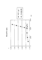
さて、図5は、無負荷時(トルクT≒0)の電流変化を、本実施形態のサーボモータ1と、特許文献1のサーボモータとについて示した図である。この図では、ω=4000[rpm]の時点で、いずれのサーボモータについてもd軸電流制御が開始されている。容易に読み取れるように、d軸電流制御開始後は、特許文献1のサーボモータにおける電機子電流が急激に増大している。これは、無負荷時ゆえ無効電流を流す必要が無いにもかかわらず、回転速度ωに応じて一意的に定まる無効電流(∝ω)を流しているからである。一方、本実施形態のサーボモータ1では、d軸電流制御開始後(ω≧4000[rpm])も電機子電流に変化が見られない。これは、無負荷のためトルクを発生させる必要がないので、速度制御器25からの総電流指令I*が略0になり、その結果、Id*=−|I*|・sinθ≒0、となり、電機子12には無効電流Idが流れないからである。
FIG. 5 is a diagram showing a change in current when no load is applied (torque T≈0) for the
図5は、無負荷時(トルクT≒0)という極端な場合について示すものであるが、この図から、低負荷時における電機子電流の様子も容易に類推できる。なお、トルク発生のためのq軸電流Iqの大きさは両サーボモータでほとんど同じなので、両サーボモータの比較においては、この影響を無視して考える。
さて、特許文献1のサーボモータでは、負荷の高低によらず回転速度ωによって一意的に決まる無効電流Idが流されるから、電機子電流の変化の様子は無負荷時の図5とほとんど同じである(厳密に言えば、q軸電流Iqの分だけ「底上げ」されている)。
一方、本実施形態のサーボモータ1では、発生トルクに応じた大きさの総電流指令I*に基づいて無効電流指令Id*=−|I*|・sinθが演算器26で演算され、これに応じて無効電流Idが電機子12に流される。低負荷時ではI*の絶対値が比較的小さな値として出力されるので、流される無効電流Idの負方向への大きさは、特許文献1におけるIdの負方向への大きさよりも小さくなる。なぜなら、特許文献1における無効電流Idは、高負荷時においても電圧飽和の発生を防止できるようにするため、比較的大きな負方向への大きさをもつものとして設定されているからである。
FIG. 5 shows the extreme case of no load (torque T≈0). From this figure, the state of the armature current at low load can be easily inferred. Since the magnitude of the q-axis current Iq for generating torque is almost the same for both servomotors, this effect is ignored in comparison between the two servomotors.
In the servo motor disclosed in
On the other hand, in the
以上のように、本実施形態のサーボモータ1によれば、従来の特許文献1記載のサーボモータに比べて、低負荷時(無負荷時含む)の電機子電流を小さくすることができ、余分な熱の発生を防止することができる。
As described above, according to the
なお、図4(A)において、ωi≦ω≦ωf、の領域でIq*(=I*・cosθ)は、因子cosθによって単調に減少していく。これはサーボモータ1におけるトルク指令T*が減少していくことを意味するから、一見、モータの高速回転時(ω≧ωi)においては発生されるトルクTが小さくなってしまうように見える。しかし、これは図4(A)が総電流指令I*を一定とする仮想的条件の下で表されているためであって、総電流指令I*が変動する実際のサーボ制御においては、以下に説明するように、発生トルクTの減少という問題は生じない。
In FIG. 4A, Iq * (= I * · cos θ) monotonously decreases by the factor cos θ in the region of ωi ≦ ω ≦ ωf. This means that the torque command T * in the
回転速度ωがωiよりも大きくなって、d軸電流制御が開始されると、図4(A)に示されるように、トルク指令T*(∝Iq*)が一時的に減少する。すると、サーボモータ1における発生トルクTが一時的に減少し、それに応じて、例えば、回転速度ωが一時的に減少する。これは、図3において速度比較器24に入力されるωが小さくなることを意味するので、速度比較器24から出力される速度偏差Δω(=ω*―ω)は大きくなる。図3において、速度制御器25は、増加したΔωを基に、より大きな総電流指令I*を演算して、出力する。すると、増加したI*を基に演算されるq軸電流指令Iq*(∝T*)も大きくなり、トルク指令T*が大きくなる。これによって、発生トルクTが大きくなるから、前記のように一時的に減少した回転速度ωもほとんど元の大きさに回復される。また、トルク指令T*の増加分は、前記したトルク指令T*の一時的な減少分を相殺するので、結果的に、モータの高速回転時、d軸電流制御が行われている状況下におけるトルク指令T*の減少を抑制できる。
When the rotational speed ω becomes larger than ωi and d-axis current control is started, the torque command T * (∝Iq * ) is temporarily reduced as shown in FIG. Then, the generated torque T in the
さて、I*2=Id*2+Iq*2、で表される総電流指令I*は、I2=Id2+Iq2、で表される電機子総電流Iを指令するものである。総電流指令I*は、図3に示されるように、速度制御器25において速度偏差Δωから算出され、演算器26に出力されるようになっているが、その際、リミッタ251の作用により、|I*|が上限値I*maxを上回らないようになっている。ここで、上限値I*maxは、電機子12における総電流の最大許容量Imaxと同一の値として設定されている。そのため、仮に|I*|>I*maxとなるようなことがあると、電機子には最大許容量Imaxを超えた総電流Iが流れてしまうことになり、異常発熱や、モータ破損の原因になる。本実施形態では、リミッタ251が常に、|I*|≦I*max、であるようにI*を制限する。これによって、電機子12にImaxを超える総電流が流れることがなくなるから、異常発熱、モータ破損等を的確に防止できる。
より具体的に説明すると、速度制御器25で算出された総電流指令I*の絶対値がI*maxを超えているとき、リミッタ251は、このI*の代わりに、予め記憶された修正電流指令I*rを演算器26に出力する。ここで、I*rは、|I*r|≦I*max、を満たす任意の数値でよいが、モータにおける発生トルクTを大きく保つ観点からは、その最大値、すなわち、|I*r|=I*max、とするのが最も好ましい。
Well, I * 2 = Id * 2 + Iq * 2, in the total current command I * is represented, is to command the armature total current I expressed in I 2 = Id 2 + Iq 2 ,. As shown in FIG. 3, the total current command I * is calculated from the speed deviation Δω in the speed controller 25 and is output to the
More specifically, when the absolute value of the total current command I * calculated by the speed controller 25 exceeds I * max, the
ところで、従来、例えば特許文献1においては、回転速度ωについての1変数関数としてIdが規定されており、モータ負荷の高低を問わず、ωによって一意的に決定される無効電流Idが流されていた。しかし、低負荷時においては、高負荷時並の絶対値の大きな無効電流は流す必要がなく、かえって、電機子を流れる総電流が不必要に大きくなってしまうという問題が生じる。また、この総電流が大きくなって最大許容量を超えると、前記の通り、異常発熱等の問題も生じてしまう。
これに対して、本発明では、低負荷時には、無効電流Idの負方向への大きさを小さく抑えることとしているので、総電流Iも大きくならない。本実施形態では、前記のように、リミッタ251によって総電流Iの絶対値が最大許容量Imaxを超えないように制限しているが、仮に、リミッタ251を設けなくても、特許文献1記載のサーボモータと比較して、低負荷時の総電流Iの絶対値を小さくできるので、|I|が最大許容量Imaxを超える可能性が低くなり、サーボモータ1の低負荷時運転を安全に行うことが可能になる。
Conventionally, for example, in
On the other hand, in the present invention, when the load is low, the magnitude of the reactive current Id in the negative direction is kept small, so the total current I does not increase. In the present embodiment, as described above, the
<第2実施形態>
続いて本発明の第2実施形態について説明する。
以下、第1実施形態において既に説明した事項について重ねて説明することは避ける。そのため、第1実施形態における各構成要素と同一の、または、対応する各構成要素については、同一符号を付して、その説明を省略、または、簡略化する。
<Second Embodiment>
Next, a second embodiment of the present invention will be described.
In the following, repeated description of matters already described in the first embodiment is avoided. Therefore, the same or corresponding components as those in the first embodiment are denoted by the same reference numerals, and the description thereof is omitted or simplified.
本実施形態では、図3におけるリミッタ251が設けられていない。リミッタ251が無いので、本発明の暫定電流指令器としての速度制御器25からの暫定電流指令I*は、そのまま、演算器26に入力される。なお、第1実施形態では、I*の呼称を「『総』電流指令」としていたが、本実施形態では、後述するように、I*は電機子12の総電流を指令するものではないので、『総』の代わりに『暫定』を付して「暫定電流指令」を、その称呼とする。ここで、『暫定』を付したのは、I*が、電機子12に対する直接の電流指令であるId*、Iq*を生成するための前段階の暫定的な電流指令であることを考慮したためである。
演算器26では、速度センサ32で測定された回転速度ωに基づいてdq電流位相角θが予め算出されている。なお、θは、ωについての1変数関数θ(ω)として定義されており、その関数形は、図4(B)に示したものと同じである。
演算器26は、この位相角θと、速度制御器25から入力された暫定電流指令I*とに基づいて、Id*=−|I*|・tanθ、Iq*=I*、で表されるd軸電流指令Id*とq軸電流指令Iq*とを演算する。
In the present embodiment, the
In the
The
演算器26には、Is*2=Id*2+Iq*2=I*2・(1+tan2θ)、で表される総電流指令Is*(≠I*)の絶対値が、上限値Is*maxを上回らないように制限するリミッタ261(図示せず)が設けられている。ここで上限値Is*maxは、第1実施形態の上限値I*maxと同一の値であり、電機子12における総電流の最大許容量Imaxと等しい。
The absolute value of the total current command Is * (≠ I * ) represented by Is * 2 = Id * 2 + Iq * 2 = I * 2 · (1 + tan 2 θ) is stored in the
リミッタ261は、演算されたId*とIq*とを基にIs*を算出して、その絶対値|Is*|をIs*maxと比較する。
|Is*|≦Is*max、のとき、リミッタ261は、dq各軸電流指令Id*、Iq*を適正であると判定し、これをそのまま、dq各軸電流比較器27d、27qに出力する。
一方、|Is*|>Is*maxのときは、このIs*を与えるId*、Iq*に基づくdq各軸電流Id、Iqを電機子12に流すと、総電流の絶対値|Is|>最大許容量Imax、となってしまい、異常発熱等の問題が生じるので、リミッタ261は、このId*、Iq*を不適正と判定する。そこで、リミッタ261は、Id*=−Is*max・sinθ、Iq*=±Is*max・cosθ、をdq各軸の修正電流指令としてdq各軸電流比較器27d、27qに出力する。なお、Iq*の式の右辺に付いている『±』は、モータ1で発生させるトルクの向きに応じて適宜Iq*の符号を選択して出力することを意味する。また、このとき、Is*2=Id*2+Iq*2=Is*max2、である。
いずれの場合も、電機子12を流れる総電流Isの絶対値が最大許容量Imax以下の値となるので、異常発熱等が生じることなく、安全にサーボモータ1を運転できる。
The limiter 261 calculates Is * based on the calculated Id * and Iq *, and compares the absolute value | Is * | with Is * max.
When | Is * | ≦ Is * max, the limiter 261 determines that the dq axis current commands Id * and Iq * are appropriate, and outputs them to the dq axis
On the other hand, when | Is * |> Is * max, when the dq axis currents Id and Iq based on Id * and Iq * giving this Is * are passed through the
In any case, since the absolute value of the total current Is flowing through the
続いて、図6を用いて、本実施形態における電流制御方法について説明する。
図6(A)中、Cは、暫定電流指令I*(>0)一定とした条件下における、q軸電流指令Iq*の回転速度ω(>0)に対する変化の様子を示すグラフである。本実施形態では、Iq*=I*なので、I*=一定、の条件下では、Iq*も一定である。これは、第1実施形態の図4(A)において、d軸電流制御が行われると(ωi≦ω≦ωf)Iq*が減少していくのと相違する。
第1実施形態では、前に詳しく説明したように、d軸電流制御状態でωが大きくなると、Iq*およびT*(∝Iq*)が一時的に減少し、出力トルクTが一時的に低下してしまうが、本実施形態ではIq*およびT*が一定なので、トルクTを安定して出力できる。
Next, the current control method in the present embodiment will be described with reference to FIG.
In FIG. 6A, C is a graph showing how the q-axis current command Iq * changes with respect to the rotational speed ω (> 0) under the condition that the provisional current command I * (> 0) is constant. In this embodiment, since Iq * = I * , Iq * is also constant under the condition that I * = constant. This is different from FIG. 4A of the first embodiment in that (qi ≦ ω ≦ ωf) Iq * decreases when d-axis current control is performed.
In the first embodiment, as described in detail above, when ω increases in the d-axis current control state, Iq * and T * (∝Iq * ) temporarily decrease, and the output torque T temporarily decreases. However, in this embodiment, since Iq * and T * are constant, the torque T can be output stably.
図6(C)にもよく示されるように、d軸電流指令Id*は、Id*=−|I*|・tanθ=−I*・tanθ(≦0:−d軸方向)、に従って出力される。ωが大きくなるにつれて(ωa→ωb)θは大きくなっていくので(θa→θb)、Id*は負方向へ大きくなっていく。ωが大きいと、電機子12に生じる逆起電力も大きくなるが、それにつれて無効電流Idを負方向へ大きくできるので、電圧飽和の発生を効果的に防止できる。
As well shown in FIG. 6C, the d-axis current command Id * is output according to Id * = − | I * | · tan θ = −I * · tan θ (≦ 0: −d axis direction). The As ω increases (ωa → ωb) θ increases (θa → θb), Id * increases in the negative direction. When ω is large, the back electromotive force generated in the
なお、本発明は前述の実施形態に限定されるものではなく、本発明の目的を達成できる範囲での変形、改良等は本発明に含まれるものである。
前記各実施形態では、回転速度ωについての関数θは、図4(B)に示される関数形を有していたが、本発明では、θは回転速さωについての増加関数であればよく、制御目的に合わせて所望の関数形を有するものを採用できる。例えば、θは、高速域(ω≧ωi:図4参照)に限らずωの全域(0≦ω≦ωf)にわたってθ≠0となるような関数であってもよいし、2次以上の関数であってもよいし、折れ線状の関数形を示すものであってもよいし、曲線状の関数形を示すものであってもよい。
It should be noted that the present invention is not limited to the above-described embodiments, and modifications, improvements, and the like within the scope that can achieve the object of the present invention are included in the present invention.
In each of the above embodiments, the function θ for the rotational speed ω has the function form shown in FIG. 4B. However, in the present invention, θ may be an increasing function for the rotational speed ω. Those having a desired function shape can be adopted according to the control purpose. For example, θ is not limited to a high speed region (ω ≧ ωi: see FIG. 4), and may be a function such that θ ≠ 0 over the entire range of ω (0 ≦ ω ≦ ωf), or a function of second order or higher. It may be a polygonal function form or a curved function form.
また、前記各実施形態では、θはωについての1変数関数θ(ω)とされていたが、本発明では、θは、回転速さωについての増加関数でありさえすれば、ω以外の変数、例えば、q軸電流IqまたはトルクT、についても変化する多変数関数であってもよい。θを、例えば、ωとTとについての2変数関数θ(ω、T)としたときは、速度センサ32に加えて、Tを測定するトルクセンサを設ける必要がある。θ(ω、T)は、この両センサで測定されたω、Tが演算器26に入力されることによって演算される。なお、このθ(ω、T)と、速度制御器25から入力される電流指令I*とから、dq各軸電流指令Id*、Iq*が演算器26によって算出されることになるが、このときのId*が|Iq*|に応じて負方向へ増加するように(ω一定の条件下)、θ(ω、T)のTについての関数形を適切に設定する必要があることに注意すべきである。また、この例において変数Tの代わりにIqを第2変数とした場合、3相/2相変換器34から出力されるIqを演算器26にも入力することにすれば、演算器26は、速度センサ32からのωと合わせて、θ(ω、Iq)を算出できる。
In each of the above embodiments, θ is a one-variable function θ (ω) with respect to ω. However, in the present invention, as long as θ is an increasing function with respect to the rotational speed ω, θ can be other than ω. A variable such as a q-axis current Iq or torque T may also be a multivariable function that changes. For example, when θ is a two-variable function θ (ω, T) for ω and T, it is necessary to provide a torque sensor for measuring T in addition to the
また、前記各実施形態では、速度制御器25は、速度偏差Δωのみを入力として電流指令I*を演算して出力していたが、本発明では、速度制御器25に、速度センサからの測定速度ωや、別途設けられるトルクセンサからの測定トルクや、3相/2相変換器34からのIdやIqを入力することによって、これらの各測定量を考慮に入れた、より適切な電流指令I*を演算し、出力させることにしてもよい。
In each of the above embodiments, the speed controller 25 calculates and outputs the current command I * with only the speed deviation Δω as an input. However, in the present invention, the speed controller 25 receives the measurement from the speed sensor. By inputting the speed ω, the measured torque from a separately provided torque sensor, and Id and Iq from the three-phase / two-
本発明は、ACサーボモータに利用できる。 The present invention can be used for an AC servo motor.
1…サーボモータ
11…界磁
12…電機子
25…速度制御器
26…演算器
32…速度センサ
251…リミッタ
261…リミッタ
Id…d軸電流(無効電流)
Iq…q軸電流(有効電流)
Id*…d軸電流指令(無効電流指令)
Iq*…q軸電流指令(有効電流指令)
θ…dq電流位相角
DESCRIPTION OF
Iq ... q-axis current (effective current)
Id * ... d-axis current command (reactive current command)
Iq * ... q-axis current command (effective current command)
θ ... dq current phase angle
Claims (9)
界磁とを備え、
前記各相の電機子巻線に電機子電流を流すことによって電機子磁束を発生させ、
この電機子磁束と前記界磁による界磁束との間の相互作用に基づいて前記電機子と前記界磁とを相対回転運動させることにより回転動力を発生するサーボモータにおいて、
電圧飽和が発生することを防止すべく、d軸方向を前記界磁束の方向とするdq変換を施した前記電機子に負のd軸電流Idを流す電流制御方法であって、
前記電機子と前記界磁との相対回転速度が一定の条件下においては、前記d軸電流Idが、前記q軸電流の大きさ|Iq|に応じて負方向へ増加するように出力する、
ことを特徴とする電流制御方法。 An armature having a multi-phase armature winding;
With field,
An armature magnetic flux is generated by passing an armature current through the armature winding of each phase,
In the servo motor that generates rotational power by causing the armature and the field to rotate relative to each other based on the interaction between the armature flux and the field flux by the field,
A current control method for causing a negative d-axis current Id to flow through the armature that has been subjected to dq conversion in which the d-axis direction is the direction of the field magnetic flux in order to prevent voltage saturation from occurring,
Under the condition that the relative rotation speed between the armature and the field is constant, the d-axis current Id is output so as to increase in the negative direction according to the magnitude | Iq | of the q-axis current.
A current control method.
I2=Id2+Iq2、で表される前記電機子を流れる総電流Iの絶対値が、前記電機子における許容電流値Imaxを超えないように制限する、
ことを特徴とする電流制御方法。 The current control method according to claim 1,
The absolute value of the total current I flowing through the armature represented by I 2 = Id 2 + Iq 2 is limited so as not to exceed the allowable current value Imax in the armature.
A current control method.
前記Idと前記Iqとは、前記電機子を流れる総電流I、および、0°≦θ<90°を満たす位相角θに対して、Id=−|I|・sinθ、Iq=I・cosθ、の関係を満足するように規定され、
前記位相角θは、前記電機子と前記界磁との相対回転の速さについての増加関数として規定される、
ことを特徴とする電流制御方法。 In the current control method according to claim 1 or 2,
The Id and the Iq are the total current I flowing through the armature and the phase angle θ satisfying 0 ° ≦ θ <90 °, Id = − | I | · sin θ, Iq = I · cos θ, To satisfy the relationship of
The phase angle θ is defined as an increasing function for the speed of relative rotation between the armature and the field.
A current control method.
前記Idと前記Iqとは、0°≦θ<90°を満たす位相角θに対して、Id=−|Iq|・tanθ、の関係を満足するように規定され、
前記位相角θは、前記電機子と前記界磁との相対回転の速さについての増加関数として規定される、
ことを特徴とする電流制御方法。 In the current control method according to claim 1 or 2,
The Id and the Iq are defined so as to satisfy the relationship of Id = − | Iq | · tan θ with respect to the phase angle θ satisfying 0 ° ≦ θ <90 °,
The phase angle θ is defined as an increasing function for the speed of relative rotation between the armature and the field.
A current control method.
界磁とを備え、
前記各相の電機子巻線に電機子電流を流すことによって電機子磁束を発生させ、
この電機子磁束と前記界磁による界磁束との間の相互作用に基づいて前記電機子と前記界磁とを相対回転運動させることにより回転動力を発生するサーボモータにおいて、
d軸方向を前記界磁束の方向とするdq変換を施した前記電機子に対する電流指令として、トルクを発生させるためのq軸電流指令Iq*と、電圧飽和の発生を防止するための負のd軸電流指令Id*とを出力する電流指令器を備え、
前記電機子と前記界磁との相対回転速度が一定の条件下においては、前記d軸電流指令Id*が、前記q軸電流指令の大きさ|Iq*|に応じて負方向へ増加するように出力される、
ことを特徴とするサーボモータ。 An armature having a multi-phase armature winding;
With field,
An armature magnetic flux is generated by passing an armature current through the armature winding of each phase,
In the servo motor that generates rotational power by causing the armature and the field to rotate relative to each other based on the interaction between the armature flux and the field flux by the field,
As a current command for the armature subjected to dq conversion with the d-axis direction as the direction of the field flux, a q-axis current command Iq * for generating torque and a negative d for preventing the occurrence of voltage saturation A current command device that outputs a shaft current command Id * is provided.
The d-axis current command Id * is increased in the negative direction according to the magnitude | Iq * | of the q-axis current command under the condition that the relative rotational speed between the armature and the field is constant. Output to the
Servo motor characterized by that.
前記電流指令器は、
前記電機子の総電流指令I*を出力する総電流指令器と、
I*2=Id*2+Iq*2、の関係を満足するように、前記I*から前記Id*および前記Iq*を演算し出力するdq電流指令器とを備え、
前記総電流指令器は、前記I*の絶対値が、前記電機子における許容電流値Imaxを超えないように制限するリミッタを備えて構成される、
ことを特徴とするサーボモータ。 The servo motor according to claim 5,
The current command device is
A total current command device for outputting the total current command I * of the armature;
A dq current command device that calculates and outputs the Id * and the Iq * from the I * so as to satisfy the relationship of I * 2 = Id * 2 + Iq * 2 .
The total current command device is configured to include a limiter that limits the absolute value of the I * so as not to exceed the allowable current value Imax in the armature.
Servo motor characterized by that.
前記相対回転運動の速さを測定する速度センサが設けられ、
前記電流指令器は、
前記電機子の総電流指令I*を出力する総電流指令器と、
前記速度センサで測定された速さから、この速さについての増加関数として、0°≦θ<90°を満たす位相角θを演算し、Id*=−|I*|・sinθ、Iq*=I*・cosθ、の関係を満足するように、前記I*から前記Id*および前記Iq*を演算して出力するdq電流指令器とを備えて構成される、
ことを特徴とするサーボモータ。 In the servomotor according to claim 5 or 6,
A speed sensor is provided for measuring the speed of the relative rotational movement;
The current command device is
A total current command device for outputting the total current command I * of the armature;
From the speed measured by the speed sensor, a phase angle θ satisfying 0 ° ≦ θ <90 ° is calculated as an increasing function for this speed, and Id * = − | I * | · sinθ, Iq * = A dq current command unit that calculates and outputs the Id * and the Iq * from the I * so as to satisfy the relationship of I * · cos θ.
Servo motor characterized by that.
前記相対回転運動の速さを測定する速度センサが設けられ、
前記電流指令器は、
暫定電流指令I*を出力する暫定電流指令器と、
前記速度センサで測定された速さから、この速さについての増加関数として、0°≦θ<90°を満たす位相角θを演算し、前記I*に対して、Id*=−|I*|・tanθ、Iq*=I*、の関係を満足する前記Id*、前記Iq*を演算して出力するdq電流指令器とを備えて構成される、
ことを特徴とするサーボモータ。 The servo motor according to claim 5,
A speed sensor is provided for measuring the speed of the relative rotational movement;
The current command device is
A provisional current command device for outputting a provisional current command I * ;
From the speed measured by said speed sensor, as an increasing function of the speed, 0 ° ≦ theta calculates the phase angle theta satisfying <90 °, with respect to the I *, Id * = - | I * | · Tan θ, Iq * = I * satisfying the relationship, Id * , dq current command device that calculates and outputs the Iq * ,
Servo motor characterized by that.
前記電流指令器は、
Is*2=Id*2+Iq*2=I*2・(1+tan2θ)、で表される前記電機子の総電流指令Is*の絶対値が、前記電機子における許容電流値Imaxを超えないように制限するリミッタを備えて構成される、
ことを特徴とするサーボモータ。 The servo motor according to claim 8, wherein
The current command device is
The absolute value of the total current command Is * of the armature represented by Is * 2 = Id * 2 + Iq * 2 = I * 2 · (1 + tan 2 θ) does not exceed the allowable current value Imax in the armature. Configured with a limiter to limit,
Servo motor characterized by that.
Priority Applications (5)
| Application Number | Priority Date | Filing Date | Title |
|---|---|---|---|
| JP2004256908A JP4555640B2 (en) | 2004-09-03 | 2004-09-03 | Servo motor current control method and servo motor |
| US11/574,608 US7728536B2 (en) | 2004-09-03 | 2005-08-18 | Servomotor current control method and servomotor |
| CNA2005800294911A CN101010869A (en) | 2004-09-03 | 2005-08-18 | Servomotor current control method and servomotor |
| PCT/JP2005/015050 WO2006027941A1 (en) | 2004-09-03 | 2005-08-18 | Servomotor current control method and servomotor |
| KR1020077007514A KR20070058579A (en) | 2004-09-03 | 2005-08-18 | Servomotor current control method and servomotor |
Applications Claiming Priority (1)
| Application Number | Priority Date | Filing Date | Title |
|---|---|---|---|
| JP2004256908A JP4555640B2 (en) | 2004-09-03 | 2004-09-03 | Servo motor current control method and servo motor |
Publications (2)
| Publication Number | Publication Date |
|---|---|
| JP2006074933A JP2006074933A (en) | 2006-03-16 |
| JP4555640B2 true JP4555640B2 (en) | 2010-10-06 |
Family
ID=36036229
Family Applications (1)
| Application Number | Title | Priority Date | Filing Date |
|---|---|---|---|
| JP2004256908A Active JP4555640B2 (en) | 2004-09-03 | 2004-09-03 | Servo motor current control method and servo motor |
Country Status (5)
| Country | Link |
|---|---|
| US (1) | US7728536B2 (en) |
| JP (1) | JP4555640B2 (en) |
| KR (1) | KR20070058579A (en) |
| CN (1) | CN101010869A (en) |
| WO (1) | WO2006027941A1 (en) |
Families Citing this family (15)
| Publication number | Priority date | Publication date | Assignee | Title |
|---|---|---|---|---|
| JP4555640B2 (en) | 2004-09-03 | 2010-10-06 | 東芝機械株式会社 | Servo motor current control method and servo motor |
| JP5265962B2 (en) | 2008-05-09 | 2013-08-14 | 東芝機械株式会社 | Current control method, current control program, recording medium, servo motor and injection molding machine for servo motor |
| EP2573794B1 (en) * | 2010-05-20 | 2022-03-23 | Hitachi High-Tech Corporation | Scanning electron microscope |
| JP5736602B2 (en) * | 2010-08-27 | 2015-06-17 | キヤノン株式会社 | Program, method, apparatus and laser processing apparatus for generating time series data of current supplied to motor |
| JP5444304B2 (en) * | 2011-10-25 | 2014-03-19 | ファナック株式会社 | Motor drive device having reactive current command generation unit |
| KR101656591B1 (en) * | 2011-11-30 | 2016-09-09 | 미쓰비시덴키 가부시키가이샤 | Inverter device for electric vehicle |
| JP6071327B2 (en) * | 2012-08-22 | 2017-02-01 | ナブテスコ株式会社 | Hybrid type construction machine control method and hybrid type construction machine |
| JP6008264B2 (en) * | 2013-05-28 | 2016-10-19 | 富士電機株式会社 | Magnetic pole position detection device for permanent magnet type synchronous motor |
| JP6203701B2 (en) * | 2014-11-13 | 2017-09-27 | 東芝機械株式会社 | Electric machine and program |
| US10439535B2 (en) * | 2015-04-27 | 2019-10-08 | Mitsubishi Electric Corporation | Control device of AC rotating machine and electric power steering device |
| WO2020046812A1 (en) * | 2018-08-28 | 2020-03-05 | Milwaukee Electric Tool Corporation | Battery-powered stand-alone motor unit |
| KR102281694B1 (en) * | 2019-04-18 | 2021-07-27 | 주식회사 코아비스 | No load detection method when controlling motor |
| WO2021092552A1 (en) | 2019-11-08 | 2021-05-14 | Milwaukee Electric Tool Corporation | Battery-powered stand-alone motor unit |
| US11791687B2 (en) | 2019-12-23 | 2023-10-17 | Milwaukee Electric Tool Corporation | Battery-powered stand-alone motor unit |
| TWI741754B (en) * | 2020-08-25 | 2021-10-01 | 東元電機股份有限公司 | Servomotor stiffness adjustment system and method thereof |
Citations (3)
| Publication number | Priority date | Publication date | Assignee | Title |
|---|---|---|---|---|
| JPH0984400A (en) * | 1995-09-14 | 1997-03-28 | Fanuc Ltd | Method for controlling current of servomotor |
| JP2001008499A (en) * | 1999-06-15 | 2001-01-12 | Mitsubishi Electric Corp | Vector control device |
| JP2001161099A (en) * | 1999-11-30 | 2001-06-12 | Meidensha Corp | Control scheme for synchronous motor |
Family Cites Families (13)
| Publication number | Priority date | Publication date | Assignee | Title |
|---|---|---|---|---|
| JP3682543B2 (en) | 1997-12-10 | 2005-08-10 | 株式会社日立製作所 | Control method of permanent magnet type synchronous motor |
| JP3728405B2 (en) | 2001-03-30 | 2005-12-21 | 山洋電気株式会社 | Control device for synchronous motor |
| JP3559258B2 (en) * | 2001-07-30 | 2004-08-25 | 三菱電機株式会社 | Steering control device |
| JP3716809B2 (en) * | 2002-04-01 | 2005-11-16 | 日産自動車株式会社 | Rotating electric machine |
| JP2004032947A (en) * | 2002-06-27 | 2004-01-29 | Aisin Aw Co Ltd | Motor |
| US7332837B2 (en) * | 2003-08-11 | 2008-02-19 | General Motors Corporation | Cooling and handling of reaction torque for an axial flux motor |
| JP4007345B2 (en) * | 2004-06-29 | 2007-11-14 | アイシン・エィ・ダブリュ株式会社 | Electric drive control device, electric drive control method, and program |
| JP4555640B2 (en) | 2004-09-03 | 2010-10-06 | 東芝機械株式会社 | Servo motor current control method and servo motor |
| JP4556572B2 (en) * | 2004-09-09 | 2010-10-06 | アイシン・エィ・ダブリュ株式会社 | Electric drive control device, electric drive control method, and program |
| EP1826899A1 (en) * | 2004-11-24 | 2007-08-29 | NSK Steering Systems Co., Ltd. | Non-connection motor, its drive control device and mortorized power steering device using drive control device of non-connection motor |
| JP4996847B2 (en) | 2005-11-28 | 2012-08-08 | 東芝機械株式会社 | Servo motor current control method, current control program, recording medium, servo motor |
| EP1997714A1 (en) * | 2006-03-17 | 2008-12-03 | NSK Ltd. | Electric power steering device |
| JP4466600B2 (en) * | 2006-03-31 | 2010-05-26 | アイシン・エィ・ダブリュ株式会社 | Electric drive control device and electric drive control method |
-
2004
- 2004-09-03 JP JP2004256908A patent/JP4555640B2/en active Active
-
2005
- 2005-08-18 KR KR1020077007514A patent/KR20070058579A/en active Search and Examination
- 2005-08-18 CN CNA2005800294911A patent/CN101010869A/en active Pending
- 2005-08-18 US US11/574,608 patent/US7728536B2/en active Active
- 2005-08-18 WO PCT/JP2005/015050 patent/WO2006027941A1/en active Application Filing
Patent Citations (3)
| Publication number | Priority date | Publication date | Assignee | Title |
|---|---|---|---|---|
| JPH0984400A (en) * | 1995-09-14 | 1997-03-28 | Fanuc Ltd | Method for controlling current of servomotor |
| JP2001008499A (en) * | 1999-06-15 | 2001-01-12 | Mitsubishi Electric Corp | Vector control device |
| JP2001161099A (en) * | 1999-11-30 | 2001-06-12 | Meidensha Corp | Control scheme for synchronous motor |
Also Published As
| Publication number | Publication date |
|---|---|
| JP2006074933A (en) | 2006-03-16 |
| WO2006027941A1 (en) | 2006-03-16 |
| US20080012521A1 (en) | 2008-01-17 |
| US7728536B2 (en) | 2010-06-01 |
| KR20070058579A (en) | 2007-06-08 |
| CN101010869A (en) | 2007-08-01 |
Similar Documents
| Publication | Publication Date | Title |
|---|---|---|
| WO2006027941A1 (en) | Servomotor current control method and servomotor | |
| JP4205157B1 (en) | Electric motor control device | |
| JP3746377B2 (en) | AC motor drive control device | |
| JP3668870B2 (en) | Synchronous motor drive system | |
| US7235947B2 (en) | Synchronous motor control method and synchronous motor control system | |
| JP5550672B2 (en) | Motor control device | |
| JP2002095300A (en) | Method of controlling permanent magnet synchronous motor | |
| JP4715576B2 (en) | Electric drive control device and electric drive control method | |
| JP2011217468A (en) | Apparatus for control of motor drive device | |
| US9935568B2 (en) | Control apparatus of rotary electric machine | |
| JP3764337B2 (en) | Control device for synchronous motor | |
| JP2000032799A (en) | Controller and control method for electric rotating machine | |
| JP4522273B2 (en) | Motor control device and motor drive system having the same | |
| JP2004032907A (en) | Controller for permanent magnet type synchronous motor | |
| JP3765437B2 (en) | Control system for synchronous motor for machine tool spindle drive | |
| JP5204463B2 (en) | Motor control device | |
| JP3637209B2 (en) | Power converter using speed sensorless vector control | |
| JP4996847B2 (en) | Servo motor current control method, current control program, recording medium, servo motor | |
| JP4596906B2 (en) | Electric motor control device | |
| JP3796556B2 (en) | Method and apparatus for controlling magnet-embedded synchronous motor | |
| JP5506534B2 (en) | Motor drive mechanism and motor control device | |
| JP2015126641A (en) | Controller of motor | |
| JP4115785B2 (en) | Inverter control device | |
| JPH09191697A (en) | Vector controlling device for ac motor | |
| JP3933348B2 (en) | Control device for embedded magnet type synchronous motor |
Legal Events
| Date | Code | Title | Description |
|---|---|---|---|
| A621 | Written request for application examination |
Free format text: JAPANESE INTERMEDIATE CODE: A621 Effective date: 20070725 |
|
| RD02 | Notification of acceptance of power of attorney |
Free format text: JAPANESE INTERMEDIATE CODE: A7422 Effective date: 20070809 |
|
| A131 | Notification of reasons for refusal |
Free format text: JAPANESE INTERMEDIATE CODE: A131 Effective date: 20100525 |
|
| A521 | Written amendment |
Free format text: JAPANESE INTERMEDIATE CODE: A523 Effective date: 20100628 |
|
| TRDD | Decision of grant or rejection written | ||
| A01 | Written decision to grant a patent or to grant a registration (utility model) |
Free format text: JAPANESE INTERMEDIATE CODE: A01 Effective date: 20100713 |
|
| A01 | Written decision to grant a patent or to grant a registration (utility model) |
Free format text: JAPANESE INTERMEDIATE CODE: A01 |
|
| A61 | First payment of annual fees (during grant procedure) |
Free format text: JAPANESE INTERMEDIATE CODE: A61 Effective date: 20100716 |
|
| FPAY | Renewal fee payment (event date is renewal date of database) |
Free format text: PAYMENT UNTIL: 20130723 Year of fee payment: 3 |
|
| R150 | Certificate of patent or registration of utility model |
Ref document number: 4555640 Country of ref document: JP Free format text: JAPANESE INTERMEDIATE CODE: R150 Free format text: JAPANESE INTERMEDIATE CODE: R150 |
|
| S533 | Written request for registration of change of name |
Free format text: JAPANESE INTERMEDIATE CODE: R313533 |
|
| R350 | Written notification of registration of transfer |
Free format text: JAPANESE INTERMEDIATE CODE: R350 |