JP4551663B2 - Pile head joint structure and construction method - Google Patents
Pile head joint structure and construction method Download PDFInfo
- Publication number
- JP4551663B2 JP4551663B2 JP2004014181A JP2004014181A JP4551663B2 JP 4551663 B2 JP4551663 B2 JP 4551663B2 JP 2004014181 A JP2004014181 A JP 2004014181A JP 2004014181 A JP2004014181 A JP 2004014181A JP 4551663 B2 JP4551663 B2 JP 4551663B2
- Authority
- JP
- Japan
- Prior art keywords
- pile
- pile head
- prefabricated
- plate
- hole
- Prior art date
- Legal status (The legal status is an assumption and is not a legal conclusion. Google has not performed a legal analysis and makes no representation as to the accuracy of the status listed.)
- Expired - Lifetime
Links
Images
Landscapes
- Foundations (AREA)
Description
本発明は、杭頭と上部構造物とを接合する杭頭接合部の構造及びその施工方法に関するものである。 The present invention relates to a structure of a pile head joint that joins a pile head and an upper structure, and a construction method thereof.
杭と上部構造物を接合する場合は、杭頭を上部構造物内に杭径程度埋め込んで接合する方法や10cm程度埋め込んで接合する方法など多様である。一般に、杭と上部構造物の接合部を剛結合構造とする場合には、杭径程度の埋め込みと補強鉄筋などによる補強の併用がなされる。剛結合構造を採用する場合は、上部構造物の地震時水平変位に杭が追随して変位することにより杭頭部に曲げモーメントが発生し、かかる曲げモーメント及び水平力に抗し得る杭耐力が要求される。一方、杭と上部構造物の接合部をピン結合構造とする場合は、上部構造物の地震時変位に杭は追随することなく、すなわち杭頭部は回転することによりかかる杭頭部に曲げモーメントは発生せず、杭頭部よりも下方に曲げモーメント(剛結合構造に比して一般的に小さな曲げモーメント)が発生する。ピン結合構造の場合は、杭に生じる曲げモーメント等が剛結合構造に比べて小さくなるものの、上部構造物の水平変位の拘束力が低下するためにかかる水平変位が大きなものとなり得る。
ここで、上部構造物とは、橋脚や建屋等の構造物全体の他に、かかる構造物を支持する底版やフーチングなどをも示すものである。
When joining a pile and an upper structure, there are various methods such as a method in which a pile head is embedded in the upper structure to the extent of the pile diameter and a method in which about 10 cm is embedded and joined. In general, when the joint between the pile and the upper structure has a rigid coupling structure, embedding of about the pile diameter and reinforcement with a reinforcing reinforcing bar are used in combination. When a rigid connection structure is adopted, a bending moment is generated in the pile head due to the displacement of the pile following the horizontal displacement of the superstructure during an earthquake, and the pile strength that can resist the bending moment and horizontal force is increased. Required. On the other hand, when the joint between the pile and the superstructure is a pin-coupled structure, the pile does not follow the earthquake displacement of the superstructure, that is, the pile head rotates and the bending moment is applied to the pile head. Does not occur, and a bending moment (generally a small bending moment compared with a rigid coupling structure) is generated below the pile head. In the case of the pin coupling structure, the bending moment generated in the pile is smaller than that of the rigid coupling structure, but the horizontal displacement can be large because the restraining force of the horizontal displacement of the upper structure is reduced.
Here, the upper structure indicates not only the entire structure such as a bridge pier and a building but also a bottom plate and a footing that support the structure.
ところで、杭と底版との接合に際しては、杭を施工後、かかる底版を現場打ちコンクリートにて施工し両者を一体化するのが一般的である。
ここで、上部構造物として橋脚を施工する場合、該橋脚が鋼製橋脚であれば、予めアンカーフレームを埋め込んだ状態で底版を現場施工し、かかるアンカーフレームと鋼製橋脚をボルト接合するとともに橋脚下部(根元)は根巻きコンクリートなどで補強等することにより施工されている。
一方、橋脚が鉄筋コンクリート橋脚の場合は、現場にて底版を構築し、かかる底版上に突出させた橋脚用柱筋に更に柱筋を継ぎ足しながら現場打ちにて橋脚の施工がおこなわれている。
By the way, when joining a pile and a bottom slab, after constructing a pile, it is common to construct such a bottom slab with cast-in-place concrete and to integrate both.
Here, when the pier is constructed as an upper structure, if the pier is a steel pier, the bottom slab is pre-constructed with the anchor frame embedded in advance, and the anchor frame and the steel pier are bolted together and the pier The lower part (root) is constructed by reinforcing it with root-wrapped concrete.
On the other hand, when the pier is a reinforced concrete pier, a bottom slab is constructed at the site, and the pier is constructed on site while further connecting the column to the pier column protruding above the bottom slab.
前記した従来の杭頭接合部の構造及びその施工方法にあっては、次のような問題点がある。
<1>杭施工後、現場にて底版やフーチングなどの鉄筋、型枠の組み立て、コンクリート打設、養生をおこなった後にその上部工の施工をおこなうこととなり、工期の短縮が困難である。
<2>底版やフーチングなどをプレハブ化した場合に、複数の杭夫々の平面配置及び高さ方向の施工誤差をかかるプレハブ部材が吸収しきれないため、工期が長期化し得る現場打ち施工を余儀なくされていた。
The above-described conventional pile head joint structure and construction method have the following problems.
<1> After the pile construction, the superstructure will be constructed after assembling the reinforcing bars such as bottom plate and footing, formwork, concrete placement and curing at the site, and it is difficult to shorten the construction period.
<2> When the prefabricated bottom plate or footing is prefabricated, the prefabricated members that take up construction errors in the plane arrangement and height direction of each of the piles cannot be fully absorbed. It was.
上記のような問題を解決するために、本発明の杭頭接合部の構造は、杭頭と上部構造物とを接合する杭頭接合部の構造において、杭が貫通可能な貫通孔を備えた、上部構造物を支持するプレハブ版又はプレハブ桁と、外周をネジ溝状に成形した杭頭と、杭を前記貫通孔に貫通させた際に前記プレハブ版又は前記プレハブ桁が係止可能であり、前記杭頭に螺合可能に成形して杭が貫通可能な貫通孔を備えた係止具と、前記プレハブ版又は前記プレハブ桁から突出した前記杭頭の上部に備えて該杭頭と該プレハブ版又は該プレハブ桁を固定可能であり、前記杭頭に螺合可能に成形して杭が貫通可能な貫通孔を備えた固定具と、からなることを特徴とする、杭頭接合部の構造である。
In order to solve the above problems, the structure of the pile head joint of the present invention includes a through hole through which the pile can penetrate in the structure of the pile head joint that joins the pile head and the upper structure. A prefabricated plate or prefabricated girder that supports the upper structure, a pile head that is formed into a thread groove on the outer periphery, and the prefabricated plate or the prefabricated girder can be locked when the pile is passed through the through hole. A locking tool having a through-hole through which the pile can penetrate and formed so as to be screwable to the pile head, and the pile head provided on the top of the pile head protruding from the prefabricated plate or the prefabricated girder, A prefabricated plate or a prefabricated girder, which can be fixed to the pile head, and is formed so as to be screwable to the pile head, and a fixing tool having a through-hole through which the pile can pass. Structure.
また、本発明の杭頭接合部の構造は、前記杭頭接合部の構造において、前記プレハブ版又は前記プレハブ桁に斜杭を接合する際に、前記係止具の上面及び前記固定具の下面に杭が貫通可能な貫通孔を備えたテーパープレートを夫々備えたことを特徴とする、杭頭接合部の構造である。 Moreover, the structure of the pile head joint portion of the present invention is the structure of the pile head joint portion, wherein when the oblique pile is joined to the prefabricated plate or the prefabricated girder, the upper surface of the locking tool and the lower surface of the fixing tool. It is the structure of the pile head junction part characterized by each including the taper plate provided with the through-hole which a pile can penetrate.
また、本発明の杭頭接合部の構造は、前記杭頭接合部の構造において、前記プレハブ版又は前記プレハブ桁に備えた前記貫通孔と杭頭の間を充填材で一体化したことを特徴とする、杭頭接合部の構造である。 Further, the structure of the pile head joint portion of the present invention is characterized in that in the structure of the pile head joint portion, the space between the through hole provided in the prefabricated plate or the prefabricated girder and the pile head is integrated with a filler. The structure of the pile head joint.
さらに、本発明の杭頭接合部の構造の施工方法は、杭頭接合部の構造を施工する施工方法であって、既施工の杭に前記係止具を設置し、前記プレハブ版又は前記プレハブ桁の前記貫通孔を杭に貫通設置し、前記プレハブ版又は前記プレハブ桁から突出した前記杭頭の上部に固定具を設置し、前記貫通孔と前記杭頭の間に前記充填材を充填して、杭と前記プレハブ版又は前記プレハブ桁を一体化することを特徴とする、杭頭接合部の構造の施工方法である。 Furthermore, the construction method for the structure of the pile head joint of the present invention is a construction method for constructing the structure of the pile head joint, wherein the locking tool is installed on an already constructed pile, and the prefabricated plate or the prefab The through hole of the girder is installed through the pile, a fixture is installed on the prefabricated plate or the top of the pile head protruding from the prefabricated girder, and the filler is filled between the through hole and the pile head. And a method for constructing a pile head joint, wherein the pile and the prefabricated plate or the prefabricated girder are integrated.
また、本発明の杭頭接合部の構造の施工方法は、杭頭接合部の構造を施工する施工方法であって、所要本数のうちの一部である既施工の前施工杭に、前記係止具を設置し、前記プレハブ版又は前記プレハブ桁の前記貫通孔を前記前施工杭に貫通設置し、前記プレハブ版又は前記プレハブ桁から突出した前記前施工杭の杭頭の上部に前記固定具を設置し、前記貫通孔と前記杭頭の間に前記充填材を充填し、所要本数のうちの残りの後施工杭と上部構造物との施工を並行しておこない、前記プレハブ版又は前記プレハブ桁及び前記前施工杭の前記杭頭と、前記後施工杭の杭頭をコンクリートにて一体化することを特徴とする、杭頭接合部の構造の施工方法である。 Moreover, the construction method of the structure of the pile head joint of the present invention is a construction method of applying the structure of the pile head joint, before construction pile already construction is part of the required number, the engagement A fastener is installed, the through hole of the prefabricated plate or the prefabricated girder is installed through the preconstructed pile, and the fixture is mounted on the top of the prefabricated pile pile head protruding from the prefabricated plate or the prefabricated girder. The prefabricated plate or the prefabricated plate is filled with the filler between the through hole and the pile head, and the remaining post-installed pile and the upper structure of the required number are installed in parallel. It is the construction method of the structure of a pile head junction part characterized by integrating the pile head of a girder and the said pre-construction pile, and the pile head of the said post-construction pile with concrete.
本発明の杭頭接合部の構造及びその施工方法は、上記した課題を解決するための手段により、次のような効果の少なくとも一つを得ることができる。
<1>プレハブ化した底版やフーチングと杭を接合するため、工期の大幅な短縮が可能となる。
<2>杭頭部に備えた係止具のレベルを調整可能とすることで複数の杭の高さ方向の誤差を吸収(調整)可能とし、プレハブ部材に備えた貫通孔の孔径または孔の大きさに施工誤差を考慮した余裕をもたせて複数の杭の平面的な誤差を吸収(調整)可能とすることで、底版やフーチングをプレハブ化する場合の杭施工誤差の問題を解消することができる。
<3>プレハブ版又はプレハブ桁を係止具及び固定具で締め付け固定することで杭と底版又はフーチングを容易かつ強固に一体化することができる。この場合、杭頭と係止具及び固定具の貫通孔が螺合可能となるようにネジ溝状に成形するのがよい。さらに、底版又はフーチングの貫通孔と杭との間に充填材を充填固化させることで、より一層強固な接合構造を形成することができる。
The structure of the pile head joint of the present invention and the construction method thereof can obtain at least one of the following effects by means for solving the above-described problems.
<1> Since the prefabricated bottom plate or footing and the pile are joined, the construction period can be greatly shortened.
<2> By making it possible to adjust the level of the locking tool provided in the pile head, it is possible to absorb (adjust) the errors in the height direction of the plurality of piles, and to adjust the diameter of the through-hole provided in the prefabricated member. It is possible to solve the problem of pile construction error when prefabricating bottom plates and footings by making it possible to absorb (adjust) the planar error of multiple piles by giving a margin considering the construction error in size. it can.
<3> The pile and the bottom plate or the footing can be integrated easily and firmly by fastening and fixing the prefabricated plate or the prefabricated girder with the locking device and the fixing device. In this case, it is preferable that the pile head, the locking tool, and the fixing tool are formed into a thread groove shape so that the through holes can be screwed together. Furthermore, an even stronger joint structure can be formed by filling and solidifying the filler between the through hole of the bottom plate or footing and the pile.
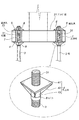
<1>杭頭接合部
杭頭接合部1は、上部構造物(底版やフーチングなど)と杭3の杭頭31の接合部のことである。本発明では、特に底版やフーチングとして後述するプレハブ版21やプレハブ桁などの工場製作された版と杭頭31との接合部を対象とするものである。以下、上部構造物としてプレハブ版21を例に杭頭接合部1の構造を説明する。
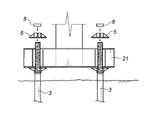
杭頭接合部1の構造は、杭3(杭頭31)が貫通可能な貫通孔23を備えたプレハブ版21と、該貫通孔23に貫通させた杭頭31、杭頭31に設けてプレハブ版21を係止させる係止具4と、プレハブ版21から突出した杭頭31の上部を固定する固定具5とから構成される(図1参照)。ここで、固定具5による固定とは、係止具4と固定具5によってプレハブ版21を上下から挟み込んで締め付けながら固定することである。
プレハブ版21と杭3の結合をより強固にするために、プレハブ版21に備えた貫通孔23と杭頭31の間に充填材7を充填固化させるのが好ましい。ここで、充填材7としては、セメントグラウト材や無収縮グラウト材、膨張性高強度グラウト材、樹脂系グラウト材などを使用することができる。
<1> Pile head joint 1 The pile head joint 1 is a joint between an upper structure (such as a bottom plate or a footing) and a
The structure of the pile head joint 1 includes a
In order to further strengthen the connection between the
本発明における杭3としては、鋼管杭やPHC杭などの既製杭のほか、マイクロパイルなどの小口径杭などを使用するのがよい。工事工程の短縮を本発明の目的の一つとしているため、かかる杭3を使用することでより工程の短縮を図ることが可能となるからである。
ここで、マイクロパイルとは、30cm以下の小口径の場所打ち杭や埋め込み杭をいう。マイクロパイルを構築するマイクロパイル工法は、ボーリングマシンによって地盤を削孔しながら鋼管(ケーシング)を支持地盤まで貫入させ、鋼管内に補強用ネジ鉄筋などを挿入した後、セメントミルクやモルタルなどのグラウト材を充填することでマイクロパイルを構築する工法である。
As the
Here, the micropile refers to a cast-in-place pile or embedded pile having a small diameter of 30 cm or less. The micropile construction method for constructing a micropile is to drill a ground with a boring machine, penetrate the steel pipe (casing) to the support ground, insert a reinforcing screw rebar, etc. into the steel pipe, and then grout cement milk, mortar, etc. It is a construction method that builds a micropile by filling materials.
また、杭頭31をネジ溝状に成形して製作し、係止具4に備えた貫通孔及び固定具5に備えた貫通孔の各内空面も杭頭31と螺合可能にネジ溝状に成形することもできる(図1参照)。
Further, the
杭3は直杭のほか、直杭と斜杭の組合せなどがあり、各設計仕様に応じた杭頭接合部1の構造を選定できる。
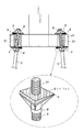
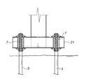
斜杭とプレハブ版21を接合する場合は、後述するテーパープレート6を係止具4の上面及び固定具5の下面とプレハブ版21との間に楔のように備えて斜杭の傾斜に適合させるのがよい(図2参照)。
The
When the inclined pile and the
<2>プレハブ版及びプレハブ桁
プレハブ版21やプレハブ桁は、上部構造物である橋脚(柱体)や壁体などを支持する版(底版など)やフーチング、桁(格子桁など)などをプレハブ化したものである。
プレハブ版21の形状は、平面視が矩形、正方形、円形など設計仕様に応じて多様に選定でき、また、その材質はコンクリート製材料や鋼製材料などが考えられる。
プレハブ版21は、複数の杭3が貫通可能な貫通孔23を備えて製作する。ここで、貫通孔23の孔径または孔の断面寸法(孔の延伸方向に垂直な断面寸法)は、杭の施工誤差を勘案して、使用する杭の杭径よりも所定の余裕幅をもって決定するのが好ましい。杭3と貫通孔23の内空面に間隙があっても、充填材7を充填固化させることによってかかる隙間を密実にでき、杭3とプレハブ版21との結合力を確保することができる。
<2> Prefabricated plates and prefabricated girders Prefabricated
The shape of the
The
<3>係止具及び固定具
係止具4は、平面板材からなりその中央に杭3が貫通可能な貫通孔を備えた係止プレート41と、係止プレート41の片面に取り付けて杭が貫通可能な筒体43、及び係止プレート41と筒体43側面に取り付けて係止プレート41のうち筒体43の外径から張り出した部分を支持する支持プレート42とから構成できる(図1参照)。使用する杭3の杭頭31がネジ溝状に成形されている場合は、筒体43の内空面も杭3と螺合可能にネジ溝状に成形するのがよい。
固定具5は、係止具4とその構成は同じであり、プレハブ版21から突出した杭頭31の上部に平らな係止プレートを下方にして杭頭31に設置するものである。
杭頭31に設置した係止具4及び固定具5でプレハブ版21を挟むように締め付けて杭3(杭頭31)とプレハブ版21を一体化する。
係止具4及び固定具5は、例えば鋼製材料にて製作することができる。
<3> Locking tool and fixing tool The
The
The pile 3 (pile head 31) and the
The
上記するように、ネジ溝状に製作した杭頭31に適合するように筒体43の内空面もネジ溝状に製作した場合、複数の杭3の打設誤差(高さ方向)等が生じても、係止具4のレベルを杭頭部3で調整することにより、すべての係止具4の支持プレート41上面のレベルを容易に一定にすることができる。また、杭頭31及び筒体43の内空面を互いに螺合可能にネジ溝状に成形することで、杭頭31と係止具4及び固定具5との取り付け強度が向上するとともに締め付け施工等も容易となる。
なお、図1に示すように、係止具4の下方、固定具5の上方には係止具4や固定具5のネジ回りによる締め付け力の低下を防止すべく、カプラー8を備えることもできる。図1では、筒体43とほぼ同外径のカプラー8を使用している実施例を示している。
As described above, when the inner hollow surface of the
As shown in FIG. 1, a
<4>テーパープレート
プレハブ版21と斜杭を接合する場合、係止具4の係止プレート41の上面とプレハブ版21の底面、及び固定具5の係止プレートの下面とプレハブ版21の上面との間には、斜杭の傾斜角だけ隙間が生じ得る。そこで、かかる隙間を埋めるために、例えば傾斜角分のテーパーを備えたプレート状のテーパープレート6を使用するのがよい(図2参照)。
テーパープレート6は、その中央(中央付近)に杭3が貫通可能な貫通孔を備えて成形される。
テーパープレート6は、係止具4や固定具5と同材質(例えば鋼製材料)にて製作することもできるし、ゴム製材料にて製作することもできる。ゴム製材料等、伸縮性のある材料にて製作する場合は、予め伸縮性能に応じてテーパー角度を杭の傾斜角よりも大きく設計しておくのが好ましい。
<4> Tapered plate When the
The
The
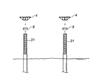
以下、図3〜図6を参照して、本発明の杭頭接合部の構造の施工方法について説明する。
まず、杭3として例えば杭頭31をネジ溝状に成形した複数のマイクロパイルを施工する。
次に、杭頭31にカプラー8を螺合するとともに係止具4も螺合させる(図3参照)。
ここで、各杭3の高さレベルに誤差がある場合は、カプラー8や係止具4のレベルを調整しながら杭頭31と螺合させ、少なくとも係止具4の係止プレート41の上面レベルが各杭3でほぼ同一レベルとなるように調整する。
Hereinafter, with reference to FIGS. 3-6, the construction method of the structure of the pile head junction part of this invention is demonstrated.
First, as the
Next, the
Here, when there is an error in the height level of each
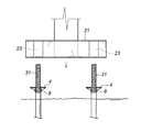
次に、プレハブ版21を図4のように吊り下ろし(又はジャッキダウンさせ)、各杭3を貫通孔23に貫通させながらプレハブ版21を複数の係止具4上に係止させる。
Next, the
プレハブ版21を各係止具4上に係止させた後、プレハブ版21の上面から突出した杭頭31に固定具5及びカプラー8を螺合させる(図5参照)。ここで、固定具8を強固に締め付けて、杭3とプレハブ版21の接合部の接合強度を確保するのがよい。
After the
固定具5を締め付けた後、杭頭31と貫通孔23の内空面との間の間隙に充填材7を充填する。ここで、充填材7の充填は、例えばプレハブ版21の上面から上記内空面に備えた充填口に連通する充填パイプを介して充填することができる(図示せず)。
かかる充填材7が固化することにより、杭3(杭頭31)とプレハブ版21がより強固に一体化される。
After fastening the
As the
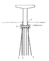
図7及び図8に、本発明の杭頭接合部の構造を備えた橋脚の実施例を示す。図7は、すべての杭3(直杭、斜杭のすべて)の数だけの貫通孔23を備えたプレハブ版21を各杭頭31に設置した実施例である。なお、本実施例では、プレハブ版21及び橋脚の根元を根巻きコンクリート9にて被覆している。
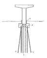
一方、図8は、施工する杭3の一部とプレハブ版21を連結した構造の実施例を示している。かかる構造を使用する利点は、上部構造物を支持し得る必要最小限の杭3を施工後、プレハブ版21を既施工の杭3と連結させ、その他の杭3の施工と上部構造物の付帯工事などを並行させることにより、全体工程の短縮を図ることができる点である。
この場合、プレハブ版21及びプレハブ版21と直接連結していない杭3とは所要の配筋を備えた根巻きコンクリート9(又は本設底版)にて一体化させるのがよい。
7 and 8 show an embodiment of a pier having the structure of a pile head joint according to the present invention. FIG. 7 shows an embodiment in which prefabricated
On the other hand, FIG. 8 shows an embodiment of a structure in which a part of the
In this case, the
1・・・・杭頭接合部
21・・・プレハブ版
23・・・貫通孔
3・・・・杭
31・・・杭頭
4・・・・係止具
5・・・・固定具
6・・・・テーパープレート
7・・・・充填材
DESCRIPTION OF SYMBOLS 1 ... Pile
Claims (5)
杭が貫通可能な貫通孔を備えた、上部構造物を支持するプレハブ版又はプレハブ桁と、
外周をネジ溝状に成形した杭頭と、
杭を前記貫通孔に貫通させた際に前記プレハブ版又は前記プレハブ桁が係止可能であり、前記杭頭に螺合可能に成形して杭が貫通可能な貫通孔を備えた係止具と、
前記プレハブ版又は前記プレハブ桁から突出した前記杭頭の上部に備えて該杭頭と該プレハブ版又は該プレハブ桁を固定可能であり、前記杭頭に螺合可能に成形して杭が貫通可能な貫通孔を備えた固定具と、からなることを特徴とする、
杭頭接合部の構造。 In the structure of the pile head joint that joins the pile head and the superstructure,
A prefabricated plate or prefabricated girder that supports the superstructure , with a through-hole through which the pile can penetrate;
A pile head whose outer periphery is shaped like a screw groove,
A locking tool provided with a through-hole through which a pile can be threaded and formed so that the prefabricated plate or the prefabricated girder can be locked when the pile is passed through the through-hole; ,
The pile head and the prefabricated plate or the prefabricated girder can be fixed to the top of the pile head protruding from the prefabricated plate or the prefabricated girder, and the pile can be penetrated by being screwed to the pile head. A fixing device having a through hole,
Pile head joint structure.
前記プレハブ版又は前記プレハブ桁に斜杭を接合する際に、前記係止具の上面及び前記固定具の下面に斜杭が貫通可能な貫通孔を備えたテーパープレートを夫々備えたことを特徴とする、
杭頭接合部の構造。 In the structure of the pile head joint part according to claim 1,
When joining the oblique pile to the prefabricated plate or the prefabricated girder, the upper surface of the locking tool and the lower surface of the fixing tool are each provided with a taper plate having a through-hole through which the oblique pile can pass. To
Pile head joint structure.
前記プレハブ版又は前記プレハブ桁に備えた前記貫通孔と杭頭の間を充填材で一体化したことを特徴とする、
杭頭接合部の構造。 In the structure of the pile head joint part according to claim 1 or claim 2,
The prefabricated plate or the prefabricated girder is integrated with a filler between the through hole and the pile head.
Pile head joint structure.
既施工の杭に、前記係止具を設置し、
前記プレハブ版又は前記プレハブ桁の前記貫通孔を杭に貫通設置し、
前記プレハブ版又は前記プレハブ桁から突出した前記杭頭の上部に固定具を設置し、
前記貫通孔と前記杭頭の間に前記充填材を充填して、杭と前記プレハブ版又は前記プレハブ桁を一体化することを特徴とする、
杭頭接合部の構造の施工方法。 A construction method for constructing the structure of the pile head joint according to claim 3,
Install the locking tool on the existing pile,
Install the through hole of the prefabricated plate or the prefabricated girder in the pile,
Install a fixture on top of the pile head protruding from the prefabricated plate or the prefabricated girder,
The filler is filled between the through hole and the pile head, and the pile and the prefabricated plate or the prefabricated girder are integrated,
Construction method for pile head joints.
所要本数のうちの一部である既施工の前施工杭に、前記係止具を設置し、
前記プレハブ版又は前記プレハブ桁の前記貫通孔を前記前施工杭に貫通設置し、
前記プレハブ版又は前記プレハブ桁から突出した前記前施工杭の杭頭の上部に前記固定具を設置し、
前記貫通孔と前記杭頭の間に前記充填材を充填し
所要本数のうちの残りの後施工杭と上部構造物との施工を並行しておこない、
前記プレハブ版又は前記プレハブ桁及び前記前施工杭の前記杭頭と、前記後施工杭の杭頭をコンクリートにて一体化することを特徴とする、
杭頭接合部の構造の施工方法。 A construction method for constructing the structure of the pile head joint according to claim 3,
In the pre-installed pre-construction pile that is a part of the required number, install the locking tool,
The through hole of the prefabricated plate or the prefabricated girder is installed through the pre-constructed pile,
Installing the fixture on top of the pile head of the pre-constructed pile protruding from the prefabricated plate or the prefabricated girder,
Filling the filler between the through hole and the pile head and performing the construction of the remaining post-construction pile and the superstructure in the required number in parallel,
The pile head of the prefabricated plate or the prefabricated girder and the pre-construction pile and the pile head of the post-construction pile are integrated with concrete,
Construction method for pile head joints.
Priority Applications (1)
| Application Number | Priority Date | Filing Date | Title |
|---|---|---|---|
| JP2004014181A JP4551663B2 (en) | 2004-01-22 | 2004-01-22 | Pile head joint structure and construction method |
Applications Claiming Priority (1)
| Application Number | Priority Date | Filing Date | Title |
|---|---|---|---|
| JP2004014181A JP4551663B2 (en) | 2004-01-22 | 2004-01-22 | Pile head joint structure and construction method |
Publications (2)
| Publication Number | Publication Date |
|---|---|
| JP2005207096A JP2005207096A (en) | 2005-08-04 |
| JP4551663B2 true JP4551663B2 (en) | 2010-09-29 |
Family
ID=34900046
Family Applications (1)
| Application Number | Title | Priority Date | Filing Date |
|---|---|---|---|
| JP2004014181A Expired - Lifetime JP4551663B2 (en) | 2004-01-22 | 2004-01-22 | Pile head joint structure and construction method |
Country Status (1)
| Country | Link |
|---|---|
| JP (1) | JP4551663B2 (en) |
Families Citing this family (3)
| Publication number | Priority date | Publication date | Assignee | Title |
|---|---|---|---|---|
| JP5467983B2 (en) * | 2009-10-02 | 2014-04-09 | 新日鉄住金エンジニアリング株式会社 | Pile head joint structure |
| JP5956214B2 (en) * | 2012-03-28 | 2016-07-27 | 日鐵住金建材株式会社 | Foundation structure for the solar cell module support |
| CN113618875B (en) * | 2021-09-14 | 2022-07-08 | 连云港市连大管桩工程有限公司 | Precast concrete square pile with reinforced connecting structure and production method thereof |
Family Cites Families (7)
| Publication number | Priority date | Publication date | Assignee | Title |
|---|---|---|---|---|
| JPS52154208A (en) * | 1976-06-18 | 1977-12-21 | Shinkouzou Gijiyutsu Kk | Preecast concrete construction |
| JPS62169022U (en) * | 1986-04-15 | 1987-10-27 | ||
| JPH0414525A (en) * | 1990-05-07 | 1992-01-20 | Shigeaki Sugiyama | Coping pile work |
| JPH0446123U (en) * | 1990-08-13 | 1992-04-20 | ||
| JP3270915B2 (en) * | 1994-03-07 | 2002-04-02 | イビデングリーンテック株式会社 | Support plate device for ground anchor |
| JPH08100432A (en) * | 1994-09-30 | 1996-04-16 | Giken Seisakusho Co Ltd | Footing device |
| JPH08109641A (en) * | 1994-10-12 | 1996-04-30 | Shimizu Corp | Fixing method of steel column base to foundation pile |
-
2004
- 2004-01-22 JP JP2004014181A patent/JP4551663B2/en not_active Expired - Lifetime
Also Published As
| Publication number | Publication date |
|---|---|
| JP2005207096A (en) | 2005-08-04 |
Similar Documents
| Publication | Publication Date | Title |
|---|---|---|
| CN101939492B (en) | Precast temporary facility structure and construction method for the same | |
| JP7103962B2 (en) | Earth retaining structure and earth retaining method | |
| KR20110058359A (en) | Insertion base plate and joint method of steel column | |
| JP4693299B2 (en) | Column base connection structure | |
| KR101870309B1 (en) | Aseismatic Reinforcement Steel Frame Structure and Aseismatic Reinforcement Method using thereof | |
| KR20100099495A (en) | Central connecting apparatus engaged with lattice type steel pipe pile and construction method of assembling slab bridge using the same | |
| JP2006104747A (en) | Joint structure and joining method of pedestal | |
| KR101908356B1 (en) | Aseismatic Reinforcement Double Steel Frame and Aseismatic Reinforcement Method using thereof | |
| KR20180128245A (en) | Bridge using temporary bridge and construction method | |
| JP7339865B2 (en) | How to install wall panels | |
| JP5456627B2 (en) | Connection structure and method of connection between pile and steel column | |
| CN216765554U (en) | Connecting structure of bridge tower and bearing platform | |
| JP4551663B2 (en) | Pile head joint structure and construction method | |
| JP3671344B2 (en) | Joint structure between foundation pile and column base and its construction method | |
| JP2009185487A (en) | Septic tank foundation structural body and its construction method | |
| US8627623B2 (en) | Modular foundation system and method | |
| JP2004011203A (en) | Precast SRC column joint structure | |
| JP2004263507A (en) | Building foundation construction method and building foundation structure | |
| JP7532735B2 (en) | Connection structure | |
| KR20200123654A (en) | Moment connection structure between cft column and pc girder | |
| JP6476483B2 (en) | Embankment resistor and construction method of embankment structure | |
| JP3851563B2 (en) | Frame reinforcement structure and its construction method | |
| JP7049980B2 (en) | Construction method of composite foundation structure | |
| JPH02164930A (en) | Foundation structure for building | |
| JP2002115324A (en) | Column base unit, column integrated column base fixing foundation structure using the column base unit, and construction method therefor |
Legal Events
| Date | Code | Title | Description |
|---|---|---|---|
| A621 | Written request for application examination |
Free format text: JAPANESE INTERMEDIATE CODE: A621 Effective date: 20060801 |
|
| A977 | Report on retrieval |
Free format text: JAPANESE INTERMEDIATE CODE: A971007 Effective date: 20081017 |
|
| A131 | Notification of reasons for refusal |
Free format text: JAPANESE INTERMEDIATE CODE: A131 Effective date: 20081028 |
|
| A521 | Request for written amendment filed |
Free format text: JAPANESE INTERMEDIATE CODE: A523 Effective date: 20081225 |
|
| A711 | Notification of change in applicant |
Free format text: JAPANESE INTERMEDIATE CODE: A712 Effective date: 20091218 |
|
| A131 | Notification of reasons for refusal |
Free format text: JAPANESE INTERMEDIATE CODE: A131 Effective date: 20100316 |
|
| A521 | Request for written amendment filed |
Free format text: JAPANESE INTERMEDIATE CODE: A523 Effective date: 20100428 |
|
| A521 | Request for written amendment filed |
Free format text: JAPANESE INTERMEDIATE CODE: A523 Effective date: 20100528 |
|
| RD02 | Notification of acceptance of power of attorney |
Free format text: JAPANESE INTERMEDIATE CODE: A7422 Effective date: 20100528 |
|
| TRDD | Decision of grant or rejection written | ||
| A01 | Written decision to grant a patent or to grant a registration (utility model) |
Free format text: JAPANESE INTERMEDIATE CODE: A01 Effective date: 20100629 |
|
| A01 | Written decision to grant a patent or to grant a registration (utility model) |
Free format text: JAPANESE INTERMEDIATE CODE: A01 |
|
| A61 | First payment of annual fees (during grant procedure) |
Free format text: JAPANESE INTERMEDIATE CODE: A61 Effective date: 20100712 |
|
| R150 | Certificate of patent or registration of utility model |
Ref document number: 4551663 Country of ref document: JP Free format text: JAPANESE INTERMEDIATE CODE: R150 Free format text: JAPANESE INTERMEDIATE CODE: R150 |
|
| FPAY | Renewal fee payment (event date is renewal date of database) |
Free format text: PAYMENT UNTIL: 20130716 Year of fee payment: 3 |
|
| R250 | Receipt of annual fees |
Free format text: JAPANESE INTERMEDIATE CODE: R250 |
|
| R250 | Receipt of annual fees |
Free format text: JAPANESE INTERMEDIATE CODE: R250 |
|
| R250 | Receipt of annual fees |
Free format text: JAPANESE INTERMEDIATE CODE: R250 |
|
| R250 | Receipt of annual fees |
Free format text: JAPANESE INTERMEDIATE CODE: R250 |
|
| R250 | Receipt of annual fees |
Free format text: JAPANESE INTERMEDIATE CODE: R250 |
|
| R250 | Receipt of annual fees |
Free format text: JAPANESE INTERMEDIATE CODE: R250 |
|
| R250 | Receipt of annual fees |
Free format text: JAPANESE INTERMEDIATE CODE: R250 |
|
| R250 | Receipt of annual fees |
Free format text: JAPANESE INTERMEDIATE CODE: R250 |
|
| R250 | Receipt of annual fees |
Free format text: JAPANESE INTERMEDIATE CODE: R250 |
|
| R250 | Receipt of annual fees |
Free format text: JAPANESE INTERMEDIATE CODE: R250 |
|
| R250 | Receipt of annual fees |
Free format text: JAPANESE INTERMEDIATE CODE: R250 |
|
| EXPY | Cancellation because of completion of term |