KR20180128245A - Bridge using temporary bridge and construction method - Google Patents
Bridge using temporary bridge and construction method Download PDFInfo
- Publication number
- KR20180128245A KR20180128245A KR1020170063558A KR20170063558A KR20180128245A KR 20180128245 A KR20180128245 A KR 20180128245A KR 1020170063558 A KR1020170063558 A KR 1020170063558A KR 20170063558 A KR20170063558 A KR 20170063558A KR 20180128245 A KR20180128245 A KR 20180128245A
- Authority
- KR
- South Korea
- Prior art keywords
- bridge
- steel pipe
- girder
- precast
- pocket portion
- Prior art date
Links
Images


Classifications
-
- E—FIXED CONSTRUCTIONS
- E01—CONSTRUCTION OF ROADS, RAILWAYS, OR BRIDGES
- E01D—CONSTRUCTION OF BRIDGES, ELEVATED ROADWAYS OR VIADUCTS; ASSEMBLY OF BRIDGES
- E01D21/00—Methods or apparatus specially adapted for erecting or assembling bridges
-
- E—FIXED CONSTRUCTIONS
- E01—CONSTRUCTION OF ROADS, RAILWAYS, OR BRIDGES
- E01D—CONSTRUCTION OF BRIDGES, ELEVATED ROADWAYS OR VIADUCTS; ASSEMBLY OF BRIDGES
- E01D15/00—Movable or portable bridges; Floating bridges
- E01D15/12—Portable or sectional bridges
-
- E—FIXED CONSTRUCTIONS
- E01—CONSTRUCTION OF ROADS, RAILWAYS, OR BRIDGES
- E01D—CONSTRUCTION OF BRIDGES, ELEVATED ROADWAYS OR VIADUCTS; ASSEMBLY OF BRIDGES
- E01D19/00—Structural or constructional details of bridges
- E01D19/005—Piers, trestles, bearings, expansion joints or parapets specially adapted for portable or sectional bridges
-
- E—FIXED CONSTRUCTIONS
- E01—CONSTRUCTION OF ROADS, RAILWAYS, OR BRIDGES
- E01D—CONSTRUCTION OF BRIDGES, ELEVATED ROADWAYS OR VIADUCTS; ASSEMBLY OF BRIDGES
- E01D2/00—Bridges characterised by the cross-section of their bearing spanning structure
-
- E—FIXED CONSTRUCTIONS
- E02—HYDRAULIC ENGINEERING; FOUNDATIONS; SOIL SHIFTING
- E02D—FOUNDATIONS; EXCAVATIONS; EMBANKMENTS; UNDERGROUND OR UNDERWATER STRUCTURES
- E02D13/00—Accessories for placing or removing piles or bulkheads, e.g. noise attenuating chambers
- E02D13/04—Guide devices; Guide frames
-
- E—FIXED CONSTRUCTIONS
- E02—HYDRAULIC ENGINEERING; FOUNDATIONS; SOIL SHIFTING
- E02D—FOUNDATIONS; EXCAVATIONS; EMBANKMENTS; UNDERGROUND OR UNDERWATER STRUCTURES
- E02D7/00—Methods or apparatus for placing sheet pile bulkheads, piles, mouldpipes, or other moulds
- E02D7/02—Placing by driving
Landscapes
- Engineering & Computer Science (AREA)
- Civil Engineering (AREA)
- Structural Engineering (AREA)
- Architecture (AREA)
- Life Sciences & Earth Sciences (AREA)
- General Life Sciences & Earth Sciences (AREA)
- Mining & Mineral Resources (AREA)
- Paleontology (AREA)
- General Engineering & Computer Science (AREA)
- Bridges Or Land Bridges (AREA)
Abstract
Description
본 발명은 교량에 관한 것으로, 보다 상세하게는 임시교량을 교량의 측면 거치대에 거치함으로써, 인양 횟수를 줄일 수 있고, 시공비용과 시간을 줄일 수 있는 임시교량을 사용한 교량 및 이의 시공방법에 관한 것이다.The present invention relates to a bridge, more particularly, to a bridge using temporary bridges capable of reducing the number of times of lifting and lowering the construction cost and time by mounting a temporary bridge on a side stand of the bridge, and a construction method thereof .
일반적으로, 교량(bridge)이라 함은 물이나 어떤 곳의 위로 건너다니도록 만든 시설물을 의미하는 것으로서, 설치하고자 하는 환경이나 특성 및 용도에 따라 다양한 공법에 의해 시공된다.In general, a bridge means a facility that is made to cross over water or a certain place. The bridge is constructed by various methods depending on the environment, characteristics and purpose of installation.
이러한 교량을 설치하기 위해서 현장에서 직접 거푸집 및 배근 공사 후 콘크리트를 타설하는 방식에 의해 구조물을 시공하는 것이 전통적이라 할 수 있으나, 이는 기본적으로 현장 상황에 의해 시공되는 구조물의 품질이 지나치게 많은 영향을 받는다는 문제점을 안고 있었다.In order to install these bridges, it is traditionally to construct the structures by placing the concrete directly after the formwork and the laying work on site, but this is basically because the quality of the structures to be installed by the on-site situation is excessively influenced I had a problem.
따라서, 최근에는 프리캐스트(Precast)에 의해 구조물을 구성하는 부재를 미리 제조하고, 이를 현장에서 조립하는 방식에 의한 공법의 연구가 활발히 진행되고 있으며, 이는 당연히 현장 상황과 관계없이 구조물의 품질을 확보할 수 있다는 장점을 갖는다.Therefore, in recent years, there has been actively studied a method of manufacturing a member constituting the structure by precast and assembling it in the field, and it is natural that the quality of the structure is secured .
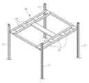
우선 도 1 및 도 2와 같이, 프리캐스트 구조물로 교량를 시공하기 앞서 교량의 강관파일(110)을 측정된 정위치에 항타하기 위해 임시교량(10)이 설치되는데, 상기 임시교량(10)은 강관파일(110)을 배치하기 위해 통공(21)이 형성된 가이드프레임(20)과 상기 가이드프레임(20)을 지지하는 가이드파일(11)로 구성된다.First, as shown in FIGS. 1 and 2, a
상기 가이드프레임(20)의 설치장소가 물이 있는 하천이나 바다인 경우에는 먼저 가도를 축조하거나 바지선(30)을 시공하여 다수개의 가이드파일(11)을 바이브로햄마(40)로 항타한 후 상기 가이드파일(11)에 가이드프레임(20)을 설치한 후 통공(21)에 강관파일(30)을 삽입한 후 항타하게 된다. 이 후 다시 역순으로 가이드프레임(20) 및 가이드 파일(11)을 해체한다.When the installation place of the
상술한 프리캐스트 구조물인 프리캐스트 바닥판(40)을 사용하려면, 정확한 위치와 높이로 강관파일(30)이 설치해야 되는데, 상기 강관파일(30)의 위치를 정확하게 항타하기 위해서는 임시교량(10)의 설치가 필수이다.In order to use the
그러나, 상기한 바와 같은 임시교량(10)은 가이드파일(11) 및 가이드프레임(20)의 번거로운 설치 및 해체작업의 반복적으로 시행함으로 필요 이상으로 전체적인 교량 설치기간과 설치비용이 소요되어 교량 시공에 소요되는 시공비가 증가되는 문제점이 있었다. 또한 그러나 이러한 임시교량(10)의 설치와 해체작업에 많은 대형장비가 투입되어 시공기간이 더욱 늘어난다는 문제점이 있었다.However, since the
따라서 이러한 문제점을 해결하기 위한 본 발명의 목적은 강관파일이 삽입될 수 있는 다수개의 통공이 구비된 가이드프레임과 상기 가이드프레임의 일측에 결합되어 있는 다수개의 가이드파일이 일체형으로 구비된 임시교량과, 상기 상기 교량의 측면의 강관파일에 결합되며, 상기 임시교량의 통공에 끼워져 임시교량을 거치시키는 거치대를 구비하여 상기 임시교량을 제거한 후 교량의 측면 거치대에 거치함으로써, 인양 횟수를 줄일 수 있고, 시공비용과 시간을 줄일 수 있는 임시교량을 사용한 교량 및 이의 시공방법을 제공하는 것이다.SUMMARY OF THE INVENTION Accordingly, the present invention has been made keeping in mind the above problems occurring in the prior art, and an object of the present invention is to provide a temporary bridge including a guide frame having a plurality of holes through which a steel pipe file can be inserted and a plurality of guide piles coupled to one side of the guide frame, The bridge is coupled to a steel pipe file on the side of the bridge and has a cradle that is inserted in the through hole of the temporary bridge to receive the temporary bridge and removes the temporary bridge and then mounts the bridge on the side cradle of the bridge, A bridge using temporary bridges capable of reducing cost and time, and a method of constructing the bridge.
상기 목적을 달성하기 위하여 본 발명은 강관파일이 삽입될 수 있는 다수개의 통공이 구비된 가이드프레임과, 상기 가이드프레임의 일측에 결합되어 있는 다수개의 가이드파일이 일체형으로 구비된 임시교량을 준비하는 단계; 상기 가이드프레임의 통공에 강관파일을 삽입 후 항타작업을 수행하는 단계; 상기 가이드프레임의 통공에 삽입되어 항타된 강관파일의 상측을 기 측정된 높이로 커팅하는 단계; 상기 임시교량을 강관파일에서 제거하여 교량의 측면 일측에 거치하는 작업을 수행하는 단계를 포함하는 임시교량을 사용한 교량의 시공방법을 제공한다.According to an aspect of the present invention, there is provided a method of preparing a temporary bridge comprising a guide frame having a plurality of through holes into which a steel pipe file can be inserted, and a plurality of guide piles coupled to one side of the guide frame, ; Inserting a steel pipe file into the through hole of the guide frame, and performing a hitching operation; Cutting the upper side of the pierced steel pipe file inserted into the through hole of the guide frame to a predetermined height; And a step of removing the temporary bridge from the steel pipe file to place the temporary bridge on one side of the bridge, thereby providing a method of constructing the bridge using the temporary bridge.
또한 상기 강관파일을 항타하는 단계 전, 강관파일를 정확한 위치로 항타하기 위하여 상기 가이드프레임의 통공에 강관파일을 삽입한 후 상기 강관파일의 외주면의 형상에 대응되는 내주면을 갖는 삽입공이 형성된 가이드플레이트가 결합되는 단계를 더 포함하고, 상기 임시교량을 제거하는 단계는 상기 강관파일에서 가이드플레이트를 제거하는 것을 더 포함할 수 있다.And a guide plate having an insertion hole having an inner circumferential surface corresponding to the shape of the outer circumferential surface of the steel pipe file after inserting the steel pipe file into the through hole of the guide frame for driving the steel pipe file to the correct position, The step of removing the temporary bridge may further include removing the guide plate from the steel pipe file.
또한 상기 임시교량을 거치하는 단계에서 상기 거치대는, 상기 교량의 측면의 강관파일에 결합되며, 상기 임시교량의 통공에 끼워져 임시교량을 거치시키는 거치돌출부가 구비될 수 있다.Also, in the step of mounting the temporary bridge, the cradle may be provided with a cradle protrusion coupled to a steel pipe file on a side surface of the bridge and inserted into the through hole of the temporary bridge to mount the temporary bridge.
또한 상기 교량의 전방에 항타된 강관파일에 가로보를 용접 또는 볼트체결로 결합하고, 상측에 캡을 씌우는 단계를 더 포함할 수 있다.Further, the method may further include the step of joining the beam to the steel pipe filed in front of the bridge by welding or bolting, and capping the upper side.
또한 상기 강관파일 위에 복수개의 거더를 설치하는 단계; 상기 복수개 거더의 상측에 포켓부가 형성된 프리캐스트 복공판을 설치하는 프리캐스트 복공판 설치단계; 상기 프리캐스트 복공판 설치단계 후에, 상기 포켓부의 내측으로 연결재를 삽입한 상태에서 상기 포켓부의 중심 위치에 대응하는 상기 거더 상측면에 연결재를 용접하는 연결재 설치단계; 상기 포켓부를 통해 채움재를 일정량 타설하는 채움재 타설단계 및 상기 프리캐스트 복공판을 고정하도록 상기 연결재의 상단에 연결판을 설치하는 연결판 설치단계를 포함하며, 상기 거더 설치단계와 상기 프리캐스트 복공판 설치단계의 사이에는, 상기 포켓부를 통해 타설되는 채움재의 누설 방지를 위해 상기 포켓부 위치의 거더 상측면에 포켓부의 둘레를 감싸도록 실링테이프를 설치하는 단계를 더 포함할 수 있다.Installing a plurality of girders on the steel pipe file; A precast laminating plate installation step of installing a precast laminating plate on which a plurality of girders are formed with pockets; A connecting member mounting step of welding the connecting member to the upper surface of the girder corresponding to the center position of the pocket portion in a state where the connecting member is inserted into the pocket portion after the precast stitching step; A filling material placing step of placing a filler material in a predetermined amount through the pocket part, and a connecting plate mounting step of installing a connecting plate at an upper end of the connecting material so as to fix the precast flat plate. In the girder mounting step and the precast flat plate mounting step The method may further include the step of installing a sealing tape on the upper surface of the girder at the position of the pocket so as to surround the periphery of the pocket portion to prevent leakage of the filler pierced through the pocket portion.
또한 상기 강관파일 위에 복수개의 거더를 설치하는 단계; 상기 복수개 거더의 상측에 포켓부가 형성된 프리캐스트 복공판을 설치하는 프리캐스트 복공판 설치단계; 상기 프리캐스트 복공판 설치단계 후에, 상기 포켓부의 내측으로 연결재를 삽입한 상태에서 상기 포켓부의 중심 위치에 대응하는 상기 거더 상측면에 연결재를 용접하는 연결재 설치단계; 상기 연결재의 외측에 쉬스를 삽입 설치하는 쉬스 설치단계 및 상기 포켓부를 통해 채움재를 타설하는 채움재 타설단계를 포함하며, 상기 거더 설치단계와 상기 프리캐스트 복공판 설치단계의 사이에는, 상기 포켓부를 통해 타설되는 채움재의 누설 방지를 위해 상기 포켓부 위치의 거더 상측면에 포켓부의 둘레를 감싸도록 실링테이프를 설치하는 단계를 포함할 수 있다.Installing a plurality of girders on the steel pipe file; A precast laminating plate installation step of installing a precast laminating plate on which a plurality of girders are formed with pockets; A connecting member mounting step of welding the connecting member to the upper surface of the girder corresponding to the center position of the pocket portion in a state where the connecting member is inserted into the pocket portion after the precast stitching step; A sheathing step of inserting a sheath on the outer side of the connecting member and a filling material placing step of placing the filling material through the pocket part, wherein the step of installing the girder and the step of installing the pre- And installing a sealing tape around the pocket portion on the upper surface of the girder at the position of the pocket to prevent leakage of the filler.
상기 두 번째 목적을 달성하기 위하여 본 발명은 해양 또는 지반에 항타되는 강관파일; 상기 강관파일의 상측에 구비된 거더; 상기 거더의 상측에 설치되는 프리캐스트 바닥판; 상기 강관파일이 삽입될 수 있는 다수개의 통공이 구비된 가이드프레임과, 상기 가이드프레임의 일측에 결합되어 있는 다수개의 가이드파일이 일체형으로 구비된 임시교량 및 상기 교량의 측면에 결합되어 상기 임시교량이 거치되는 거치대를 포함하는 임시교량을 사용한 교량을 제공한다.In order to accomplish the above second object, the present invention provides a steel pipe file for marine or geotechnical purposes; A girder provided on the upper side of the steel pipe file; A precast bottom plate provided on the upper side of the girder; A temporary bridge including a plurality of guide piles coupled to one side of the guide frame and having a plurality of holes through which the steel pipe file can be inserted; Provides bridges using temporary bridges that include a mounted stand.
또한 상기 거치대는, 상기 임시교량의 통공에 끼워져 거치시키는 거치돌출부가 마련될 수 있다.Further, the cradle may be provided with a cradle protrusion which is inserted into the through hole of the temporary bridge to be mounted thereon.
상기에서 설명한 본 발명의 임시교량을 사용한 교량 및 이의 시공방법에 의하면, 상기 임시교량을 제거한 후 분해하여 교량의 외부로 옮겨놓았던 번거로운 종래의 작업을 탈피하여 상기 임시교량을 교량의 측면 거치대에 거치함으로써, 인양 횟수를 줄일 수 있고, 별도의 바지선 구매도 불필요하여 시공비용과 시간을 줄일 수 있는 효과가 있다.According to the bridge using the temporary bridge of the present invention and the method of applying the bridge of the present invention described above, the temporary bridge is removed and then disassembled and transferred to the outside of the bridge to avoid the troublesome conventional work and the temporary bridge is mounted on the side stand of the bridge , The number of lifting can be reduced, and a separate barge line is not required to be purchased, thereby reducing construction costs and time.
도 1은 종래의 교량의 시공방법을 도시한 사시도이다.
도 2는 도 1의 가이드프레임을 도시한 사시도이다.
도 3은 본 발명에 의한 임시교량을 사용한 교량의 시공방법을 도시한 사시도이고, 도 4는 도 3의 정면도이다.
도 5는 본 발명에 의한 임시교량을 사용한 교량의 시공방법을 도시한 사시도이다.
도 6은 본 발명에 의한 임시교량에서 임시교량 및 강관파일을 도시한 사시도이다.
도 7은 도 6의 임시교량의 가이드프레임과 강관파일의 결합된 모습을 도시한 사시도이다.
도 8은 도 6에서 강관파일을 커팅하는 모습을 도시한 사시도이다.
도 9는 도 3에서 임시교량을 교량의 거치대에 옮겨놓은 모습을 도시한 사시도이다.
도 10은 도 9를 다른 각에서 바라본 모습을 도시한 사시도이다.
도 11은 도 9의 강관파일에 캡과 가로보가 구비된 모습을 도시한 사시도이다.
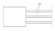
도 12는 본 발명에 의한 거더를 도시한 사시도이다.
도 13은 도 12의 거더가 결합된 모습을 도시한 사시도이다.
도 14는 본 발명에 따른 가교를 나타내는 사시도이다.
도 15는 본 발명에 따른 가교의 다양한 실시예를 나타내는 단면도이다.
도 16은 본 발명에 따른 가교의 시공방법에서 거더 설치단계를 나타내는 도면이다.
도 17은 본 발명에 따른 가교의 시공방법에서 프리캐스트 바닥팍 설치단계를 나타내는 도면이다.
도 18는 본 발명에 따른 가교의 시공방법에서 연결재 설치단계를 나타내는 도면이다.
도 19은 본 발명에 따른 가교의 시공방법에서 채움재 설치단계를 나타내는 도면이다.
도 20은 본 발명에 따른 가교의 시공방법에서 연결판 설치단계를 나타내는 도면이다.
도 21는 본 발명에 따른 가교의 시공이 완료된 상태를 나타내는 도면이다.
도 22은 본 발명에 따른 가교의 해체방법을 나타내는 도면이다.1 is a perspective view showing a conventional method of constructing a bridge.
Fig. 2 is a perspective view showing the guide frame of Fig. 1. Fig.
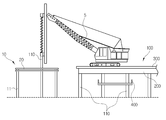
FIG. 3 is a perspective view showing a construction method of a bridge using a temporary bridge according to the present invention, and FIG. 4 is a front view of FIG.
5 is a perspective view showing a construction method of a bridge using a temporary bridge according to the present invention.
6 is a perspective view showing a temporary bridge and a steel pipe file in the temporary bridge according to the present invention.
FIG. 7 is a perspective view showing a combined state of the guide frame and the steel pipe file of the temporary bridge of FIG. 6. FIG.
8 is a perspective view showing a state in which a steel pipe file is cut in FIG.
Fig. 9 is a perspective view showing a state in which a temporary bridge is transferred to a cradle of a bridge in Fig. 3;
10 is a perspective view showing a state in which FIG. 9 is viewed from another angle.
FIG. 11 is a perspective view showing a state in which a cap and a beam are provided in the steel pipe file of FIG. 9. FIG.
12 is a perspective view showing a girder according to the present invention.
13 is a perspective view showing a state in which the girders of FIG. 12 are combined.
14 is a perspective view showing crosslinking according to the present invention.
15 is a cross-sectional view showing various embodiments of crosslinking according to the present invention.
16 is a view showing a step of installing a girder in a method of cross-linking according to the present invention.
17 is a view showing a step of installing a precast floor in a method of constructing a bridge according to the present invention.
FIG. 18 is a view showing a step of installing a connecting material in the crosslinking method according to the present invention.
19 is a view showing a step of installing a filler in the method of crosslinking according to the present invention.
20 is a view showing the step of installing a connecting plate in the method of crosslinking according to the present invention.
21 is a view showing a state in which the construction of the crosslinking according to the present invention is completed.
22 is a view showing a method of disassembling a bridge according to the present invention.
본 발명을 충분히 이해하기 위해서 본 발명의 바람직한 실시예를 첨부 도면을 참조하여 설명한다. 본 발명의 실시예는 여러 가지 형태로 변형될 수 있으며, 본 발명의 범위가 아래에서 상세히 설명하는 실시예로 한정되는 것으로 해석되어서는 안 된다. 본 실시예는 당업계에서 평균적인 지식을 가진 자에게 본 발명을 보다 완전하게 설명하기 위하여 제공 되는 것이다. 따라서 도면에서의 요소의 형상 등은 보다 명확한 설명을 강조하기 위해서 과장되어 표현될 수 있다. 각 도면에서 동일한 부재는 동일한 참조부호로 도시한 경우가 있음을 유의하여야 한다. 또한, 본 발명의 요지를 불필요하게 흐릴 수 있다고 판단되는 공지 기능 및 구성에 대한 상세한 기술은 생략된다.For a better understanding of the present invention, a preferred embodiment of the present invention will be described with reference to the accompanying drawings. The embodiments of the present invention may be modified into various forms, and the scope of the present invention should not be construed as being limited to the embodiments described in detail below. The present embodiments are provided to enable those skilled in the art to more fully understand the present invention. Therefore, the shapes and the like of the elements in the drawings can be exaggeratedly expressed to emphasize a clearer description. It should be noted that in the drawings, the same members are denoted by the same reference numerals. Further, detailed descriptions of well-known functions and configurations that may be unnecessarily obscured by the gist of the present invention are omitted.
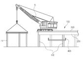
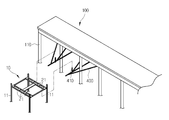
도 3 내지 도 14는 본 발명에 의한 교량(100)의 시공방법을 설명하기 위한 사시도이다. 도 3은 본 발명에 의한 임시교량을 사용한 교량의 시공방법을 도시한 사시도이고, 도 4는 도 3의 정면도이다.3 to 14 are perspective views for explaining a method of constructing the
도 3 및 도 4에 도시된 바와 같이, 상기 교량(100)은 전진 시공 방식을 택하며, 하천 또는 지반에 항타된 강관파일(110)과, 상기 교량(100)의 상측에 구비된 거더(200)와, 상기 거더(200)의 상측에 설치되는 프리캐스트 바닥판(300)을 포함한다.As shown in FIGS. 3 and 4, the
우선 본 발명에 의한 교량(100)은 상기 강관파일(110)이 삽입될 수 있는 다수개의 통공(21)이 구비된 가이드프레임(20)과, 상기 가이드프레임(20)의 일측에 결합되어 있는 다수개의 가이드파일(11)이 일체형으로 구비된다. 상기 임시교량(10)은 현장에서 미리 제작되어 교량(100)의 전방향으로 크레인(5)에 의하여 인양되고, 상기 가이드파일(11)은 바이브로 햄머에 의하여 항타되어 임시교량(10)이 고정된다.The
즉 본 발명은 강관파일(110)이 삽입될 수 있는 다수개의 통공(21)이 구비된 가이드프레임(20)과, 상기 가이드프레임(20)의 일측에 결합되어 있는 다수개의 가이드파일(11)이 일체형으로 구비된 임시교량(10)을 준비하는 단계(S1)를 포함한다.That is, the present invention is characterized in that a
도 5는 본 발명에 의한 임시교량을 사용한 교량의 시공방법을 도시한 사시도이고, 도 6은 본 발명에 의한 임시교량에서 임시교량 및 강관파일을 도시한 사시도이다.FIG. 5 is a perspective view showing a construction method of a bridge using a temporary bridge according to the present invention, and FIG. 6 is a perspective view showing a temporary bridge and a steel pipe file in a temporary bridge according to the present invention.
도 5 및 도 6과 같이, 상기 가이드프레임(20)의 통공(21)에 강관파일(110)이 삽입된 후 바이브로 햄머 및/또는 오가드릴에 의한 항타작업이 수행된다. 이 경우 상술한 바와 같이, 상기 강관파일(110)은 가이드프레임(20)의 통공(21)에 끼워져 항타되므로 그 항타위치를 정확하게 맞출 수 있다. 특히 상기 교량(100)에는 프리캐스트 바닥판(300)이 설치되므로, 항타위치를 정확하게 맞추지 못하면, 프리캐스트 바닥판(300)이 파손될 수 있는 우려가 있다.5 and 6, after the
이에 본 발명은 상기 가이드프레임(20)의 통공(21)에 강관파일(110)을 삽입 후 항타작업을 수행하는 단계(S2)를 포함한다.Accordingly, the present invention includes a step S2 of inserting a
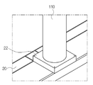
도 7은 도 6의 임시교량의 가이드프레임과 강관파일의 결합된 모습을 도시한 사시도이다.FIG. 7 is a perspective view showing a combined state of the guide frame and the steel pipe file of the temporary bridge of FIG. 6. FIG.
도 7과 같이, 상기 강관파일(110)을 가이드프레임(20)의 통공(21)에 끼워져 항타하는 단계(S2) 전에 강관파일(110)를 정확한 위치로 항타하기 위하여 상기 가이드프레임(20)의 통공(21)에 강관파일(110)을 삽입한 후 상기 강관파일(110)의 외주면의 형상에 대응되는 내주면을 갖는 삽입공이 형성된 가이드플레이트(22)가 결합되는 단계(S1-1)를 더 포함할 수 있다.7, in order to mount the
도 8은 도 6에서 강관파일을 커팅하는 모습을 도시한 사시도이다.8 is a perspective view showing a state in which a steel pipe file is cut in FIG.
도 8과 같이, 가이드프레임(20)의 통공(21)에 삽입되어 항타된 다수개의 강관파일(110)의 상측을 기 측정된 높이로 정확하게 커팅하는 단계(S3)를 포함한다.8, cutting the upper side of the plurality of steel tube piles 110 inserted into the through
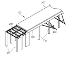
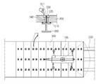
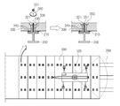
도 9는 도 3에서 임시교량을 교량의 거치대에 옮겨놓은 모습을 도시한 사시도이고, 도 10은 도 9를 다른 각에서 바라본 모습을 도시한 사시도이다.FIG. 9 is a perspective view showing a state in which a temporary bridge is transferred to a cradle of a bridge in FIG. 3, and FIG. 10 is a perspective view showing a state where FIG. 9 is viewed from another angle.
도 9 및 도 10과 같이, 본 발명은 강관파일(110)에서 필요에 따라 가이드플레이트(22)를 제거하고, 임시교량(10)을 강관파일(110)에서 제거하여 교량(100)의 측면 일측에 거치하는 작업을 수행하는 단계(S4)를 포함한다.9 and 10, according to the present invention, the
종래에는 상기 임시교량(10)을 제거한 후 분해하여 교량(100)의 외부로 옮겨놓았으나, 추후 가이드파일(11)의 항타 작업 시 임시교량(10)을 다시 가지고 와서 특정 위치에 다시 인양해야 하는 문제가 있었다. 특히 교량(100)이 해양에 건설되는 경우에는 마땅히 놓을 장소가 없어 바지선을 별도로 구비해야 하는 문제가 있었다.The
본 발명에서는 상기 임시교량(10)의 사용 후 가이드플레이트(22)를 제거하고 크레인(5)을 이용하여 임시교량(10)을 강관파일(110)로부터 들어올려 교량(100)의 측면에 마련된 거치대(400)에 거치함으로써 상술한 문제점을 해결할 수 있다.The
자세하게는 상기 거치대(400)는 교량(100)의 측면의 강관파일(110)에 결합되며, 상기 임시교량(10)의 통공(21)에 끼워져 거치시키는 거치돌출부(410)가 마련된다. 이에 상기 임시교량(10)을 인양하여 통공(21)이 거치돌출부(410)에 끼워질 수 있도록 임시교량(10)을 거치시키게 된다. 추후 임시교량(10)의 재사용을 위해 임시교량(10)을 다시 인양하여 교량(100)의 전방으로 배치할 수 있다.In detail, the
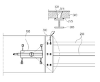
도 11은 도 9의 강관파일에 캡과 가로보가 구비된 모습을 도시한 사시도이다.FIG. 11 is a perspective view showing a state in which a cap and a beam are provided in the steel pipe file of FIG. 9. FIG.
도 11와 같이, 상기 교량(100)의 전방에 항타된 강관파일(110)의 내구성을 높이기 위해서 상기 강관파일(110)에 가로보(111)를 용접 또는 볼트체결로 결합하고, 상측에 캡(112)을 씌우는 단계(S4-1)를 더 포함할 수 있다.As shown in FIG. 11, a
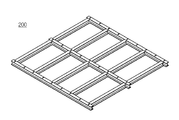
도 12는 본 발명에 의한 거더를 도시한 사시도이고, 도 13은 도 12의 거더가 결합된 모습을 도시한 사시도이다.FIG. 12 is a perspective view showing a girder according to the present invention, and FIG. 13 is a perspective view showing a combined state of the girder of FIG.
도 12 및 도 13과 같이, 거더(200)를 준비하는 단계로, 상기 거더(200)는 현장에서 미리 제작되어 강관파일(110)의 캡(112)의 상측으로 인양되어 상기 캡(112)에 결합된다. 이 후 상기 거더(200)의 상측에는 프리캐스트 바닥판(300)이 결합된다.12 and 13, the
도 14 내지 도 22 는 본 발명의 다른 실시예에 의한 임시교량을 사용한 교량 및 이의 시공방법을 설명하기 위한 도면으로, 도 3 내지 도 13의 실시예에 연장하여 적용될 수 있다.FIGS. 14 to 22 are views for explaining a bridge using a temporary bridge according to another embodiment of the present invention and a method of constructing the same, and may be extended to the embodiments of FIGS. 3 to 13.
도 14는 본 발명에 따른 가교를 나타내는 사시도이다.14 is a perspective view showing crosslinking according to the present invention.
도 14와 같이, 본 발명의 다른 실시예에 따른 교량(100) 구조는, 거더(200), 프리캐스트 바닥판(300), 연결재(330), 채움재(340) 및 연결판(350)을 포함한다.14, the structure of a
상기 거더(200)는, "H"형태의 강재 거더(200)이며, 하부구조물(미도시) 위에 복수개 설치되는데, 상기 하부구조물은, 본 발명이 적용되는 구조물에 따라 다른데, 일예로 교각이나 교대가 될 수도 있고, 또는 통상 H빔 등의 철골을 이용해 지반에 정착되어 세워지는 기둥이 될 수도 있으며, 본 실시예에서는 캡(112)이 구비된 강관파일(110)의 상측 횡방향으로 서로 일정간격 이격되어 복수개 설치되는 것으로 설명하기로 한다.The
상기 프리캐스트 바닥판(300)은, 콘크리트로 형성되는 것으로서, 상기 복수개 거더(200)의 상측에 안착 설치된다. 즉, 상기 프리캐스트 바닥판(300)은 복수개의 거더(200) 위에 직교하는 방향으로 배치되어 상기 복수개의 거더(200)를 연결하게 되는데, 이때 상기 프리캐스트 바닥판(300)의 양단부는 상기 거더(200)를 벗어나 외측방향으로 더 길게 형성되기 때문에, 상기 프리캐스트 바닥판(300)의 하측에 배치되는 거더(200)의 개수를 감소할 수 있어 경제성을 향상시킬 수 있다.The
한편, 상기 거더(200)는, 단일 프리캐스트 바닥판(300)의 길이에 따라 도 2와 같이 2개가 설치되거나, 또는 도 6와 같이 3개나 그 이상이 설치될 수 있다.2, the
또한, 프리캐스트 바닥판(300)은, 장기사용으로 인한 내구성 저하가 없고, 강재 미사용으로 인해 소음 감소와 미끄럼 방지 성능이 우수하고, 상부 코팅이 필요없으므로 유지보수가 불필요한 장점이 있다.In addition, the
그리고, 상기 프리캐스트 바닥판(300)에는, 복수개의 포켓부(321)가 관통 형성되는데, 상기 포켓부(321)는 상기 프리캐스트 바닥판(300)이 안착되는 거더(200)와 대응하는 위치에 형성된다. 도면에서는 하나의 프리캐스트 바닥판(300)에 4개의 포켓부(321)를 형성하였다. 상기 포켓부(321)는 4각 형상으로 형성되는 것이 바람직하지만, 4각 형상 외에도 원형 등 다른 형상도 가능하다.The
한편, 상기 거더(200) 상측에 설치되는 프리캐스트 바닥판(300) 위에 크레인(5)을 직접 진입시켜 상기 크레인(5)을 이동시켜 가면서 상기 프리캐스트 바닥판(300)을 설치(전진 가설)하게 된다.The
그리고, 상기 거더(200)의 상측면에는, 상기 프리캐스트 바닥판(300)과 상기 거더(200)의 사이를 일정간격 이격시키는 복수개의 스페이스 블럭(211)이 설치된다.The upper surface of the
상기 복수개의 스페이스 블럭(211)의 두께에 따라 상기 프리캐스트 바닥판(300)의 수평을 조절할 수 있다.And the horizontal of the
한편, 상기 거더(200)의 상측면에 상기 스페이스 블럭(211)을 먼저 설치한 후, 상기 프리캐스트 바닥판(300)을 안착 설치하게 된다.Meanwhile, the
그리고, 상기 포켓부(321) 위치의 거더(200) 상측면에는, 상기 포켓부(321)를 통해 타설되는 채움재(340)의 누설 방지를 위해 실링테이프(215)가 설치된다.A sealing
즉, 상기 프리캐스트 바닥판(300)이 상기 스페이스 블럭(211)에 의해 상기 거더(200)의 상측면으로부터 일정간격 이격되어 있기 때문에 상기 포켓부(321)를 통해 채움재(340)를 타설하게 되면 상기 이격된 공간으로 누설되므로, 상기 거더(200)의 상측면에 상기 포켓부(321)의 둘레를 감싸도록 실링테이프(215)를 부착함으로써 채움재(340)의 누설을 방지할 수 있다. 상기 실링테이프(215)는 상기 포켓부(321) 처럼 4각 형태로 형성되지만, 상기 포켓부(321) 보다 크게 형성 형성된다.That is, since the
그리고, 상기 연결재(330)는, 상기 포켓부(321) 위치에 대응하는 상기 거더(200) 상측면에 연결 설치된다. 즉, 상기 연결재(330)은 상기 포켓부(321)의 내측에 위치하면서 상기 거더(200)의 상측면에 용접되어 연결된다. 상기 연결재(330)는, 상기 프리캐스트 바닥판(300)을 거더(200)에 설치한 후에 설치하게 된다.The connecting
한편, 상기 연결재(330)을 프리캐스트 바닥판(300) 보다 나중에 설치할 경우에는, 상기 거더(200)의 상측에 상기 프리캐스트 바닥판(300)을 설치한 후, 상기 프리캐스트 바닥판(300)의 포켓부(321) 내측으로 상기 연결재(330)을 삽입하여 상기 거더(200)의 상측면과 용접하게 되며, 이처럼 상기 연결재(330)을 프리캐스트 바닥판(300) 보다 나중에 설치할 수도 있어 상기 프리캐스트 바닥판(300)의 설치 위치나 수평을 조절하기가 용이하다.When the connecting
그리고, 상기 채움재(340)는, 상기 포켓부(321)를 통해 타설되어 상기 거더(200)와 프리캐스트 바닥판(300)을 합성하게 된다.The
상기 채움재(340)로는, 무수축 모르타르를 사용하는 것이 바람직하지만 여기에 한정되지 않고 목적에 따라 변경 가능하다.As the
도 15는 본 발명에 따른 가교의 다양한 실시예를 나타내는 단면도이다.15 is a cross-sectional view showing various embodiments of crosslinking according to the present invention.
상기 채움재(340)는, 도 15의 (b)(c)(d)와 같이 상기 거더(200)와 프리캐스트 바닥판(300) 사이의 상기 실링테이프(215) 내측 공간에만 타설할 수도 있고, 또는 도 15의 (a)(e)(f)와 같이 상기 거더(200)와 프리캐스트 바닥판(300) 사이의 상기 실링테이프(215) 내측 공간 및 상기 포켓부(321)의 내측 공간까지 모두 타설할 수도 있다.The filling
한편, 도 15의 (a)(e)(f)와 같이 상기 포켓부(321)의 내측 공간까지 채움재(340)를 타설하는 경우에는, 채움재(340) 타설전에 상기 연결재(330)의 외측에 쉬스(335)를 삽입 설치하는 것이 바람직하다.15 (a), (e) and (f), when the filling
상기 쉬스(335)는 상기 연결재(330)과 채움재(340)의 사이를 이격시킴으로써, 상기 프리캐스트 바닥판(300)의 해체가 용이하도록 하게 된다.The
그리고, 상기 연결판(350)은, 상기 연결재(330)의 상단에 결합되어 상기 프리캐스트 바닥판(300)을 상기 거더(200)측에 고정시키게 된다.The connecting
이때, 프리캐스트 바닥판(300)의 포켓부(321) 상단에는 상기 연결판(350)이 수용되는 수용홈(322)이 형성된다. 물론, 상기 수용홈(322) 없이 상기 연결판(350)을 프리캐스트 바닥판(300)의 상측면에 안착할 수도 있다.At this time, a receiving
또한, 상기 연결재(330)의 상단에 설치된 연결판(350)은, 도 15의 (a)(b)와 같이 상기 포켓부(321)의 수용홈(322)에 안착된 상태에서 너트(51)로 고정될 수도 있고, 또는 도 15의 (c)(d)와 같이 상기 너트 없이 상기 연결판(350)을 직접 연결재(330)의 상단에 나사결합 할 수도 있다.The
이처럼, 상기 연결재(330)의 상단에 연결판(350)을 설치하게 되면, 상기 프리캐스트 바닥판(300)이 상기 연결판(350)에 걸리게 되면서 상기 거더(200)측에 고정되게 되며 이로인해 프리캐스트 바닥판(300)의 들뜸이나 유동이 방지된다.When the connecting
상기에서는 상기 연결재(330)의 상단에 연결판(350)이 설치된 구조에서 대해서 설명하였지만, 다른 실시예로서, 도 15의 (e)(f)와 같이 상기 연결판(350)을 생략한 구조도 가능하다.15 (e) and FIG. 15 (f) illustrate a structure in which the connecting
상기 연결판(350)을 생략한 교량(100) 구조는, 도 15의 (e)(f)와 같이 거더(200)와, 프리캐스트 바닥판(300)과, 연결재(330)와, 쉬스(335)와, 채움재(340)로 구성되며, 연결판(350)을 생략한 것을 제외하면 앞서 설명한 교량(100) 구조와 동일한 구성이다.The structure of the
다만, 상기 연결판(350)을 생략한 구조에서는, 상기 포켓부(321)는 상측이 넓고 하측이 좁은 사다리꼴 단면으로 형성되고, 상기 연결재(330)은 상측이 좁고 하측이 넓은 사다리꼴 단면으로 형성된다.However, in the structure in which the connecting
이때, 상기 연결재(330)의 외측에 삽입되는 쉬스(335) 역시 연결재(330)과 동일한 사다리꼴 형태로 형성된다.At this time, the
또한, 상기 채움재(340)는, 상기 거더(200)와 프리캐스트 바닥판(300) 사이의 상기 실링테이프(215) 내측 공간 및 상기 포켓부(321)의 내측 공간까지 모두 타설되어 상기 프리캐스트 바닥판(300)과 거더(200)를 합성하게 된다.The
한편, 상기 연결재(330) 및 쉬스(335)를 사다리꼴 형태로 형성함으로써, 프리캐스트 바닥판(300)의 해체시 용이하게 할 수 있다. 물론 해체시에는 상기 채움재(340)를 파쇄하게 된다.Meanwhile, by forming the connecting
아울러, 상기와 같이 연결판(350)을 생략한 구조에서는 상기 채움재(340)에 의한 합성 및 상기 프리캐스트 바닥판(300)의 자중에 의해 상기 프리캐스트 바닥판(300)의 들뜸 현상을 방지하게 된다.In addition, in the structure in which the connecting
그리고, 상기 연결재(330)을 사다리꼴 형태로 형성하지 않고 원기둥 형태로 형성할 수도 있다. 이 경우에는 해체가 용이하도록 연결재(330)의 높이를 낮게 형성하는 것이 바람직하다.The
이와 같이, 본 발명은, 도 15에 도시된 바와 같이, 연결재(330) 및 연결판(350)의 간편한 연결 구조와, 상기 프리캐스트 바닥판(300) 위에 크레인(5)을 진입시켜 설치 및 해체하도록 함으로써, 교량(100)의 설치 및 해체가 용이하고 이로인해 재활용 및 유지보수가 용이하며 공사기간도 단축할 수 있다.15, the present invention provides a simple connection structure of the connecting
이에 이어서 본 발명에 따른 교량(100)의 시공방법은, 거더 설치단계(S5)와, 프리캐스트 바닥판 설치단계(S6)와, 연결재 설치단계(S7)와, 채움재 타설단계(S8)와, 연결판 설치단계(S9)를 더 포함하여 이루어진다.The method of constructing the
도 16은 본 발명에 따른 가교의 시공방법에서 거더 설치단계를 나타내는 도면이다.16 is a view showing a step of installing a girder in a method of cross-linking according to the present invention.
상기 거더 설치단계(S1)는, 도 16과 같이 상기 하부구조물 위에 복수개의 거더(200)를 설치하는 단계이다. 즉, 상기 하부구조물인 교각이나 교대 또는 지반에 정착되어 세워지는 기둥 위에 상기 거더(200)를 설치하게 된다.The girder installation step S1 is a step of installing a plurality of
그리고, 상기 거더 설치단계(S5)와 상기 프리캐스트 바닥판 설치단계(S6)의 사이에는, 상기 프리캐스트 바닥판(300)이 안착될 상기 거더(200)의 상측면에 복수개의 스페이스 블럭(211)을 설치하는 단계와, 상기 포켓부(321) 위치의 거더(200) 상측면에 상기 포켓부(321)를 통해 타설되는 채움재(340)의 누설 방지를 위해 실링테이프(215)를 설치하는 단계를 진행하게 된다.Between the girder installation step S5 and the precast deck installation step S6, a plurality of space blocks 211 are formed on the upper side of the
상기 스페이스 블럭(211)은, 상기 프리캐스트 바닥판(300)과 상기 거더(200)의 사이를 일정간격 이격시키게 되며, 스페이스 블럭(211)의 두께에 따라 상기 프리캐스트 바닥판(300)의 수평을 조절할 수 있다.The
또한, 상기 실링테이프(215)는 상기 포켓부(321)의 둘레를 감싸도록 부착함으로써, 상기 포켓부(321)를 통해 타설되는 채움재(340)의 누설을 방지할 수 있다. 한편, 상기 실링테이프(215)는 상기 포켓부(321) 보다 크게 형성 형성된다.In addition, the sealing
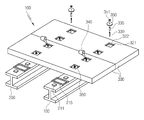
도 17은 본 발명에 따른 가교의 시공방법에서 프리캐스트 바닥팍 설치단계를 나타내는 도면이다.17 is a view showing a step of installing a precast floor in a method of constructing a bridge according to the present invention.
상기 프리캐스트 바닥판 설치단계(S6)는, 도 17와 같이, 상기 복수개 거더(200)의 상측에 포켓부(321)가 형성된 프리캐스트 바닥판(300)을 설치하는 단계이다.The precast deck installation step S6 is a step of installing a
상기 프리캐스트 바닥판(300)은, 상기 거더(200)의 상측에서 상기 스페이스 블럭(211) 및 실링테이프(215) 위에 안착되게 된다. 또한, 상기 프리캐스트 바닥판(300)의 설치시에는, 상기 거더(200) 위에 아직 연결재(330)이 없기 때문에 프리캐스트 바닥판(300)의 설치 위치나 수평 조절을 간편하게 할 수 있다. 상기 포켓부(321)는, 도면과 같은 사각 형태 뿐만 아니라 다른 형태로 가능하다.The
상기 포켓부(321)의 상단에는 상기 연결판(350)이 수용되는 수용홈(322)이 형성된다.At the upper end of the
상기 프리캐스트 바닥판 설치단계(S6)에서는, 상기 거더(200) 상측에 설치되는 상기 프리캐스트 바닥판(300) 위에 크레인(5)을 직접 진입시켜 상기 크레인(5)을 이동시켜 가면서 상기 프리캐스트 바닥판(300)을 설치(전진가설)하게 되고, 상기 크레인(5)이 지나간 후의 프리캐스트 바닥판(300)에서는 후술하는 연결재 설치단계(S7)를 진행하게 된다.In the precast deck installation step S6, the
상기 프리캐스트 바닥판(300) 위에서 크레인(5)을 이용하여 프리캐스트 바닥판(300)을 전진가설하는 경우에는, 상기 프리캐스트 바닥판(300) 위로 작업차량을 진입시켜 상기 크레인(5)에 프리캐스트 바닥판(300)을 공급할 수 있다.When the
이처럼, 교량(100)를 시공하는데 있어서, 종래기술과 같이 크레인을 교량 아래의 바닥에 배치하여 시공하는 것이 통상적인 기술이었으나, 본 발명에서는 교량(100)의 프리캐스트 바닥판(300) 위에 크레인(5)을 진입시켜 전진 가설하도록 함으로써, 프리캐스트 바닥판(300)의 설치가 용이하고 공사기간도 단축할 수 있는 것이다.In this way, it is a conventional technique to place the crane on the floor below the bridge as in the conventional technique in the construction of the
한편, 상기 프리캐스트 바닥판 설치단계(S6)를 진행한 후 상기 연결재 설치단계(S7)를 진행할 수도 있지만, 반대로 상기 연결재 설치단계(S7)를 진행한 후 상기 프리캐스트 바닥판 설치단계(S2)를 진행할 수도 있다.However, it is also possible to proceed with the connecting material mounting step S7 after the precast bottom plate mounting step S6. However, in the precast deck installing step S2 after the connecting material mounting step S7, .
도 18는 본 발명에 따른 가교의 시공방법에서 연결재 설치단계를 나타내는 도면이다.FIG. 18 is a view showing a step of installing a connecting material in the crosslinking method according to the present invention.
상기 연결재 설치단계(S7)는, 도 18와 같이, 상기 프리캐스트 바닥판 설치단계(S6) 후에, 상기 포켓부(321)의 내측으로 연결재(330)을 삽입한 상태에서 상기 포켓부(321)의 중심 위치에 대응하는 상기 거더(200) 상측면에 연결재(330)을 용접하는 단계이다.18, after the precast bottom plate mounting step S6, the connecting
상기 연결재(330)을 프리캐스트 바닥판(300) 설치 후에 설치하는 경우에는 상기 포켓부(321)의 내측으로 상기 연결재(330)을 삽입한 상태에서 상기 거더(200)의 상측면에 용접하면 된다.When the connecting
한편, 상기 연결재(330)을 프리캐스트 바닥판(300) 설치 후에 설치하게 되면, 프리캐스트 바닥판(300)의 설치 위치나 수평 조절이 용이하고, 상기 프리캐스트 바닥판(300)과 연결재(330) 간에 제조오차 및 조립오차 등을 신경쓸 필요가 없어 시공이 편리하다.If the connecting
그리고, 상기 포켓부(321)의 내측 공간까지 채움재(340)가 타설되는 구조일 경우에는, 채움재(340) 타설전에 상기 연결재(330)의 외측에 쉬스(335)를 삽입 설치하게 된다.When the
도 19은 본 발명에 따른 가교의 시공방법에서 채움재 설치단계를 나타내는 도면이다.19 is a view showing a step of installing a filler in the method of crosslinking according to the present invention.
상기 채움재 타설단계(S8)는, 도 19과 같이, 상기 포켓부(321)를 통해 채움재(340)를 일정량 타설하여 상기 거더(200)와 프리캐스트 바닥판(300)을 합성하는 단계이다.The filling material placing step S8 is a step of combining the
상기 채움재(340)로는, 무수축 모르타르를 사용하는 것이 바람직하지만 여기에 한정되지 않고 목적에 따라 변경 가능하다.As the
상기 채움재 타설단계(S8)는, 도 15의 (b)(c)(d) 와 같이 상기 거더(200)와 프리캐스트 바닥판(300) 사이의 상기 실링테이프(215) 내측 공간에만 타설할 수도 있고, 또는 도 3의 (a)(e)(f)와 같이 상기 거더(200)와 프리캐스트 바닥판(300) 사이의 상기 실링테이프(215) 내측 공간 및 상기 포켓부(321)의 내측 공간까지 모두 타설할 수도 있다.The filling material placing step S8 may be performed only in the space inside the sealing
도 20은 본 발명에 따른 가교의 시공방법에서 연결판 설치단계를 나타내는 도면이다.20 is a view showing the step of installing a connecting plate in the method of crosslinking according to the present invention.
상기 연결판 설치단계(S9)는, 도 20과 같이, 상기 프리캐스트 바닥판(300)을 고정하도록 상기 연결재(330)의 상단에 연결판(350)을 설치하는 단계이다.The connection plate installation step S9 is a step of installing the
즉, 상기 연결재(330)의 상단에 연결판(350)을 설치함으로써 상기 프리캐스트 바닥판(300)을 상기 거더(200)측에 고정시키는 것이다.That is, the connecting
이때, 상기 연결판(350)은, 상기 포켓부(321)의 수용홈(322)에 안착된 상태에서 너트(51)로 고정하거나, 또는 상기 너트 없이 상기 연결판(350)을 직접 연결재(330)의 상단에 나사결합하여 설치할 수 있다.The connecting
이처럼, 상기 연결재(330)의 상단에 연결판(350)을 설치하게 되면, 상기 프리캐스트 바닥판(300)이 상기 연결판(350)에 걸리게 되면서 상기 거더(200)측에 고정되게 되며 이로인해 프리캐스트 바닥판(300)의 들뜸이나 유동이 방지된다.When the connecting
도 21는 본 발명에 따른 가교의 시공이 완료된 상태를 나타내는 도면이다.21 is a view showing a state in which the construction of the crosslinking according to the present invention is completed.
한편, 상기 연결판(350)을 설치한 후에는 도 21와 같이 상기 포켓부(321)의 수용홈(322)에 채움재(45)를 타설하여 마감하거나 별도의 캡(미도시)으로 마감하여 시공을 완료하게 된다.After the
그리고, 다른 실시예로서, 상기 연결판(350)을 생략하는 시공방법에서는, 거더 설치단계(S5)와, 프리캐스트 바닥판 설치단계(S2)와, 연결재 설치단계(S8)까지는 상기와 동일하고, 상기 연결재 설치단계(S7) 이후에는 상기 연결재(330)의 외측에 쉬스(335)를 삽입 설치하는 쉬스 설치단계와, 상기 포켓부(321)를 통해 채움재(340)를 타설하는 채움재 타설단계(S8)를 진행하고 마무리 된다.In another embodiment, in the construction method of omitting the connecting
상기 연결판(350)을 생략한 경우에는, 도 15의 (e)(f)와 같이, 상기 포켓부(321)는 상측이 넓고 하측이 좁은 사다리꼴 단면으로 형성되고, 상기 연결재(330)은 상측이 좁고 하측이 넓은 사다리꼴 단면으로 형성된다.15 (e) and 15 (f), the
이때, 상기 연결재(330)의 외측에 삽입되는 쉬스(335) 역시 연결재(330)과 동일한 사다리꼴 형태로 형성된다.At this time, the
또한, 상기 채움재 타설단계(S8)에서는, 도 3의 (e)(f)와 같이, 상기 거더(200)와 프리캐스트 바닥판(300) 사이의 상기 실링테이프(215) 내측 공간 및 상기 포켓부(321)의 내측 공간까지 모두 타설되어 상기 프리캐스트 바닥판(300)과 거더(200)를 합성하게 된다.3 (e) and 3 (f), the inner space of the sealing
한편, 상기 연결재(330)을 사다리꼴 형태로 형성하지 않고 원기둥 형태로 형성할 경우에는 연결재(330)의 높이를 낮게 형성하는 것이 바람직하다.If the connecting
도 22은 본 발명에 따른 가교의 해체방법을 나타내는 도면이다.22 is a view showing a method of disassembling a bridge according to the present invention.
그리고, 본 발명에 따른 교량(100)의 해체방법은, 도 22 및 도 22와 같이, 연결판 해체 및 채움재 파쇄 단계(S10)과, 프리캐스트 바닥판 해체 단계(S20)와, 연결재 제거 단계(S30)와, 거더 해체 단계(S40)로 이루어진다.The method of disassembling the
상기 연결판 해체 및 채움재 파쇄 단계(S10)는, 상기 연결재(330)의 상단에 결합된 연결판(350)을 먼저 분리한 후, 채움재(340)를 파쇄하는 단계이다.The step of disassembling the connection plate and the step of crushing the filler material may be performed by first separating the
이때, 상기 연결판(350)의 상측에 캡이 설치된 경우에는 캡을 먼저 제거하게 되며, 상기 연결판(350)의 상측에 채움재(45)가 타설된 경우에는 상기 채움재(45)를 먼저 파쇄한 후, 연결판(350) 해체 및 연결판(350) 하측의 채움재(340)를 파쇄하게 된다.In this case, when the cap is installed on the connecting
상기 프리캐스트 바닥판 해체 단계(S20)는, 크레인(5)을 이용하여 프리캐스트 바닥판(300)을 인상하여 해체하는 단계이다.The pre-cast bottom plate disassembling step S20 is a step of pulling up the
즉, 도 22와 같이 상기 프리캐스트 바닥판(300) 위에 크레인(5)을 진입시켜 상기 크레인(5)을 이동시켜 가면서 상기 프리캐스트 바닥판(300)을 인상하여 해체하는 것이다.That is, as shown in FIG. 22, the
이때, 상기 프리캐스트 바닥판(300) 위에 작업차량을 진입시켜 상기 크레인(5)에 의해 해체되고 있는 프리캐스트 바닥판(300)을 운반하게 된다.At this time, the work vehicle enters the
상기 포켓부(321)내의 채움재(340)가 파쇄된 상태이므로 프리캐스트 바닥판(300)을 쉽게 인상하여 해체할 수 있다.Since the filling
상기 연결재 제거 단계(S30)는, 상기 거더(200)의 상측면에 용접된 상태의 연결재(330)을 제거하는 단계이다. 이때, 상기 연결재(330)의 외측에 쉬스(335)가 설치된 경우에는 쉬스(335)를 먼저 제거하게 된다.The connecting material removing step S30 is a step of removing the connecting
상기 거더 해체 단계(S40)는, 하부구조물 위에 설치된 거더(200)를 크레인(5)을 이용하여 해체하는 단계이다. 상기 거더(200)가 해체된 이후에는 하부구조물을 해체하면 교량(100)의 해체가 완료된다.The girder dismantling step S40 is a step of dismantling the
이상에서 설명된 본 발명의 임시교량을 사용한 교량 및 이의 시공방법의 실시예는 예시적인 것에 불과하며, 본 발명이 속한 기술분야의 통상의 지식을 가진 자라면 이로부터 다양한 변형 및 균등한 타 실시예가 가능하다는 점을 잘 알 수 있을 것이다. 그러므로 본 발명은 상기의 상세한 설명에서 언급되는 형태로만 한정되는 것은 아님을 잘 이해할 수 있을 것이다. 따라서 본 발명의 진정한 기술적 보호 범위는 첨부된 특허청구범위의 기술적 사상에 의해 정해져야 할 것이다. 또한, 본 발명은 첨부된 청구범위에 의해 정의되는 본 발명의 정신과 그 범위 내에 있는 모든 변형물과 균등물 및 대체물을 포함하는 것으로 이해되어야 한다.It will be apparent to those skilled in the art that various modifications and equivalent arrangements may be made without departing from the scope of the present invention as set forth in the appended claims. You can see that it is possible. Therefore, it is to be understood that the present invention is not limited to the above-described embodiments. Accordingly, the true scope of the present invention should be determined by the technical idea of the appended claims. It is also to be understood that the invention includes all modifications, equivalents, and alternatives falling within the spirit and scope of the invention as defined by the appended claims.
10 : 임시교량
11 : 가이드파일
20 : 가이드프레임
22 : 가이드플레이트
21 : 통공
40 : 바이브로햄마
100 : 교량
110 : 강관파일
111 : 가로보
112 : 캡
200 : 거더
300 : 프리캐스트 바닥판
330 : 연결재
340 : 채움재
350 : 연결판
400 : 거치대
410 : 거치돌출부10: temporary bridge 11: guide file
20: guide frame 22: guide plate
21: Void 40: Vibro hammer
100: Bridge 110: Steel pipe file
111: crossbar 112: cap
200: girder 300: precast deck
330: connecting material 340: filler
350: connecting plate 400: cradle
410:
Claims (8)
상기 가이드프레임(20)의 통공(21)에 강관파일(110)을 삽입 후 항타작업을 수행하는 단계(S2);
상기 가이드프레임(20)의 통공(21)에 삽입되어 항타된 강관파일(110)의 상측을 기 측정된 높이로 커팅하는 단계(S3);
상기 임시교량(10)을 강관파일(110)에서 제거하여 교량(100)의 측면 일측에 거치하는 작업을 수행하는 단계(S4)를 포함하는 임시교량을 사용한 교량의 시공방법.A guide frame 20 having a plurality of through holes 21 into which a steel pipe 110 can be inserted and a plurality of guide pawls 11 coupled to one side of the guide frame 20, Preparing a temporary bridge 10 (S1);
(S2) of inserting a steel pipe file (110) into the through hole (21) of the guide frame (20) and carrying out a paving operation;
(S3) cutting the upper side of the bulged steel pipe pile (110) inserted into the through hole (21) of the guide frame (20) to a measured height;
A step (S4) of removing the temporary bridge (10) from the steel pipe pile (110) and mounting it on one lateral side of the bridge (100).
상기 강관파일(110)을 항타하는 단계(S2) 전,
강관파일(110)를 정확한 위치로 항타하기 위하여 상기 가이드프레임(20)의 통공(21)에 강관파일(110)을 삽입한 후 상기 강관파일(110)의 외주면의 형상에 대응되는 내주면을 갖는 삽입공이 형성된 가이드플레이트(22)가 결합되는 단계(S1-1)를 더 포함하고,
상기 임시교량(10)을 제거 및 거치하는 단계(S4)는 상기 강관파일(110)에서 가이드플레이트(22)를 제거하는 것을 더 포함하는 임시교량을 사용한 교량의 시공방법.The method according to claim 1,
Before step S2 of hitting the steel pipe file 110,
After inserting the steel pipe file 110 into the through hole 21 of the guide frame 20 in order to move the steel pipe file 110 to the correct position and then inserting the steel pipe file 110 having an inner circumferential surface corresponding to the shape of the outer circumferential surface of the steel pipe file 110, Further comprising a step (S1-1) of joining the ball guide plate (22)
The step (S4) of removing and mounting the temporary bridge (10) further comprises removing the guide plate (22) from the steel pipe pile (110).
상기 임시교량(10)을 제거 및 거치하는 단계에서 상기 거치대(400)는,
상기 교량(100)의 측면의 강관파일(110)에 결합되며, 상기 임시교량(10)의 통공(21)에 끼워져 임시교량(10)을 거치시키는 거치돌출부(410)가 구비되는 임시교량을 사용한 교량의 시공방법.The method according to claim 1,
In the step of removing and mounting the temporary bridge 10,
A temporary bridge which is coupled to the steel pipe pile 110 on the side of the bridge 100 and is provided with a mounting protrusion 410 fitted in the through hole 21 of the temporary bridge 10 to mount the temporary bridge 10 Construction method of bridges.
상기 교량(100)의 전방에 항타된 강관파일(110)에 가로보(111)를 용접 또는 볼트체결로 결합하고, 상측에 캡(112)을 씌우는 단계(S4-1)를 더 포함하는 임시교량을 사용한 교량의 시공방법.The method according to claim 1,
Further comprising the step (S4-1) of joining the beam 111 to the steel pipe pile 110 stuck to the front of the bridge 100 by welding or bolting and covering the cap 112 on the upper side, Construction method of used bridges.
상기 강관파일(110) 위에 복수개의 거더(10)를 설치하는 단계(S5);
상기 복수개 거더(10)의 상측에 포켓부(21)가 형성된 프리캐스트 복공판(20)을 설치하는 프리캐스트 복공판 설치단계(S6);
상기 프리캐스트 복공판 설치단계(S6) 후에, 상기 포켓부(21)의 내측으로 연결재(30)를 삽입한 상태에서 상기 포켓부(21)의 중심 위치에 대응하는 상기 거더(10) 상측면에 연결재(30)를 용접하는 연결재 설치단계(S7);
상기 포켓부(21)를 통해 채움재(40)를 일정량 타설하는 채움재 타설단계(S8) 및
상기 프리캐스트 복공판(20)을 고정하도록 상기 연결재(30)의 상단에 연결판(50)을 설치하는 연결판 설치단계(S9)를 포함하며,
상기 거더 설치단계(S5)와 상기 프리캐스트 복공판 설치단계(S6)의 사이에는, 상기 포켓부(21)를 통해 타설되는 채움재(40)의 누설 방지를 위해 상기 포켓부(21) 위치의 거더(10) 상측면에 포켓부(21)의 둘레를 감싸도록 실링테이프(15)를 설치하는 단계를 더 포함하는 임시교량을 사용한 교량의 시공방법The method according to claim 1,
Installing (S5) a plurality of girders (10) on the steel pipe pile (110);
A step (S6) of installing a precast laminating plate (20) in which a precast laminating plate (20) having pockets (21) formed on the upper side of the plurality of girders (10) is installed;
The connecting member 30 is inserted into the pocket portion 21 and the connecting member 30 is inserted into the side surface of the girder 10 corresponding to the center position of the pocket portion 21 in the state where the connecting member 30 is inserted into the pocket portion 21 after the pre- (S7) of welding a joint member (30);
A filling material placing step (S8) of placing a filler material (40) in a predetermined amount through the pocket portion (21)
And a connection plate installation step (S9) of installing a connection plate (50) at an upper end of the connection member (30) so as to fix the precast laminating board (20)
Between the girder installation step S5 and the precast stitched plate installation step S6 there is provided a girder at the position of the pocket 21 for preventing leakage of the filler material 40 placed through the pocket 21 10. A method of constructing a bridge using temporary bridges, further comprising the step of providing a sealing tape (15) on the upper side surface so as to surround the periphery of the pocket portion (21)
상기 강관파일(110) 위에 복수개의 거더(10)를 설치하는 단계(S5);
상기 복수개 거더(10)의 상측에 포켓부(21)가 형성된 프리캐스트 복공판(20)을 설치하는 프리캐스트 복공판 설치단계(S6);
상기 프리캐스트 복공판 설치단계(S6) 후에, 상기 포켓부(21)의 내측으로 연결재(30)를 삽입한 상태에서 상기 포켓부(21)의 중심 위치에 대응하는 상기 거더(10) 상측면에 연결재(30)를 용접하는 연결재 설치단계(S7);
상기 연결재(30)의 외측에 쉬스(35)를 삽입 설치하는 쉬스 설치단계 및
상기 포켓부(21)를 통해 채움재(40)를 타설하는 채움재 타설단계(S8)를 포함하며,
상기 거더 설치단계(S6)와 상기 프리캐스트 복공판 설치단계(S6)의 사이에는, 상기 포켓부(21)를 통해 타설되는 채움재(40)의 누설 방지를 위해 상기 포켓부(21) 위치의 거더(10) 상측면에 포켓부(21)의 둘레를 감싸도록 실링테이프(15)를 설치하는 단계를 포함하는 임시교량을 사용한 교량의 시공방법.The method according to claim 1,
Installing (S5) a plurality of girders (10) on the steel pipe pile (110);
A step (S6) of installing a precast laminating plate (20) in which a precast laminating plate (20) having pockets (21) formed on the upper side of the plurality of girders (10) is installed;
The connecting member 30 is inserted into the pocket portion 21 and the connecting member 30 is inserted into the side surface of the girder 10 corresponding to the center position of the pocket portion 21 in the state where the connecting member 30 is inserted into the pocket portion 21 after the pre- (S7) of welding a joint member (30);
A sheathing step of inserting a sheath 35 into the outside of the connecting member 30;
And a filling material placing step (S8) for pouring the filling material (40) through the pocket portion (21)
Between the girder installation step S6 and the precast stitching step installation step S6 a girder at the position of the pocket portion 21 for preventing leakage of the filler material 40 pushed through the pocket portion 21 10. A method of constructing a bridge using a temporary bridge, comprising the steps of: providing a sealing tape (15) on the upper side of the pocket (21) to surround the periphery of the pocket (21).
상기 강관파일(110)의 상측에 구비된 거더(200);
상기 거더(200)의 상측에 설치되는 프리캐스트 바닥판(300);
상기 강관파일(110)이 삽입될 수 있는 다수개의 통공(21)이 구비된 가이드프레임(20)과, 상기 가이드프레임(20)의 일측에 결합되어 있는 다수개의 가이드파일(11)이 일체형으로 구비된 임시교량(10) 및
상기 교량(100)의 측면에 결합되어 상기 임시교량(10)이 거치되는 거치대(400)를 포함하는 임시교량을 사용한 교량.A steel pipe file 110 that is hulled in the ocean or on the ground;
A girder 200 provided on the upper side of the steel pipe 110;
A precast bottom plate 300 installed on the upper side of the girder 200;
A guide frame 20 having a plurality of through holes 21 into which the steel pipe 110 can be inserted and a plurality of guide pawls 11 coupled to one side of the guide frame 20, The temporary bridge 10 and
And a cradle (400) coupled to a side surface of the bridge (100) and on which the temporary bridge (10) is mounted.
상기 거치대(400)는,
상기 임시교량(10)의 통공(21)에 끼워져 거치시키는 거치돌출부(410)가 마련되는 임시교량을 사용한 교량.The method of claim 7,
The cradle (400)
A temporary protruding portion (410) fitted to the through hole (21) of the temporary bridge (10) is provided.
Priority Applications (1)
| Application Number | Priority Date | Filing Date | Title |
|---|---|---|---|
| KR1020170063558A KR102012367B1 (en) | 2017-05-23 | 2017-05-23 | Bridge using temporary bridge and construction method |
Applications Claiming Priority (1)
| Application Number | Priority Date | Filing Date | Title |
|---|---|---|---|
| KR1020170063558A KR102012367B1 (en) | 2017-05-23 | 2017-05-23 | Bridge using temporary bridge and construction method |
Publications (2)
| Publication Number | Publication Date |
|---|---|
| KR20180128245A true KR20180128245A (en) | 2018-12-03 |
| KR102012367B1 KR102012367B1 (en) | 2019-10-21 |
Family
ID=64743303
Family Applications (1)
| Application Number | Title | Priority Date | Filing Date |
|---|---|---|---|
| KR1020170063558A KR102012367B1 (en) | 2017-05-23 | 2017-05-23 | Bridge using temporary bridge and construction method |
Country Status (1)
| Country | Link |
|---|---|
| KR (1) | KR102012367B1 (en) |
Cited By (4)
| Publication number | Priority date | Publication date | Assignee | Title |
|---|---|---|---|---|
| CN109914440A (en) * | 2019-03-14 | 2019-06-21 | 中铁二院工程集团有限责任公司 | The anti-skid structure of the big ability of w type and construction method |
| CN110468721A (en) * | 2019-08-29 | 2019-11-19 | 中铁大桥局集团有限公司 | A kind of large span trestle Cantilever Construction Method |
| CN110847223A (en) * | 2019-12-10 | 2020-02-28 | 安徽开源路桥有限责任公司 | Positioning construction ship capable of completing overwater steel pipe pile sinking operation |
| WO2024021426A1 (en) * | 2022-07-26 | 2024-02-01 | 中国港湾工程有限责任公司 | Fully staged steel trestle and construction method therefor |
Citations (2)
| Publication number | Priority date | Publication date | Assignee | Title |
|---|---|---|---|---|
| KR101542192B1 (en) * | 2014-12-02 | 2015-08-05 | 우경기술주식회사 | The structure of steel bridge system and method for constructing bridge using the same |
| KR101588593B1 (en) * | 2015-03-25 | 2016-01-26 | 김근택 | Temporary bridge construction method |
-
2017
- 2017-05-23 KR KR1020170063558A patent/KR102012367B1/en active IP Right Grant
Patent Citations (2)
| Publication number | Priority date | Publication date | Assignee | Title |
|---|---|---|---|---|
| KR101542192B1 (en) * | 2014-12-02 | 2015-08-05 | 우경기술주식회사 | The structure of steel bridge system and method for constructing bridge using the same |
| KR101588593B1 (en) * | 2015-03-25 | 2016-01-26 | 김근택 | Temporary bridge construction method |
Cited By (5)
| Publication number | Priority date | Publication date | Assignee | Title |
|---|---|---|---|---|
| CN109914440A (en) * | 2019-03-14 | 2019-06-21 | 中铁二院工程集团有限责任公司 | The anti-skid structure of the big ability of w type and construction method |
| CN109914440B (en) * | 2019-03-14 | 2023-09-22 | 中铁二院工程集团有限责任公司 | Construction method of w-type high-capacity anti-slip structure |
| CN110468721A (en) * | 2019-08-29 | 2019-11-19 | 中铁大桥局集团有限公司 | A kind of large span trestle Cantilever Construction Method |
| CN110847223A (en) * | 2019-12-10 | 2020-02-28 | 安徽开源路桥有限责任公司 | Positioning construction ship capable of completing overwater steel pipe pile sinking operation |
| WO2024021426A1 (en) * | 2022-07-26 | 2024-02-01 | 中国港湾工程有限责任公司 | Fully staged steel trestle and construction method therefor |
Also Published As
| Publication number | Publication date |
|---|---|
| KR102012367B1 (en) | 2019-10-21 |
Similar Documents
| Publication | Publication Date | Title |
|---|---|---|
| US8056299B2 (en) | Foundation construction for superstructures | |
| KR20180128245A (en) | Bridge using temporary bridge and construction method | |
| KR101242476B1 (en) | Base construct method of building and base construct member of building | |
| KR101588593B1 (en) | Temporary bridge construction method | |
| JP5278828B2 (en) | How to install the jacket | |
| JP2007205077A (en) | Temporary coffering method | |
| KR101687495B1 (en) | Partial top-down construction method for building underground structures | |
| JP7194471B2 (en) | Annular cofferdam and excavation work temporary facility structure and construction method using square pipe with variable cross-section | |
| JP2007327244A (en) | Method and structure for temporarily coffering underwater structure | |
| KR101440566B1 (en) | Housing bracket for constructing foundation of pier in the water and construction method of foundation of pier using the same | |
| KR100933660B1 (en) | Structure for supporting stone wall for reinforcement and construction method thereof | |
| KR101858407B1 (en) | Method of connection of Pre-cast structure with pile foundation | |
| KR20190022132A (en) | Top-down method using precast-concrete colum | |
| KR20200124949A (en) | Anchor Tension way sheathing structure and sheathing method of construction | |
| JP6658616B2 (en) | Construction method of pile type structure | |
| KR101401057B1 (en) | Method to build underground structures using the pillars and the stigma and steel beam and slab structures are formed | |
| KR20160000702A (en) | Fastening member used in concrete filled steel tube and its using concrete filled steel tube mounting structure and method and its includes build underground structure and method | |
| KR101436119B1 (en) | Holding apparatus for CFT column and the construction method of the CFT column using it | |
| KR102184900B1 (en) | Temporary retaining wall structure using circular steel pipe and construction method thereof | |
| KR101210368B1 (en) | Uniting Method of Temporary earth wall with basement exterior Wall using Couplers and Bolts. | |
| KR20120020738A (en) | Pillar foundation structure and construction method thereof | |
| CN111877314B (en) | Construction method for constructing underground continuous wall by adopting chain precast concrete piles | |
| KR101050824B1 (en) | Pier constructing method for expanding using oscillator on brideg expanding of upper part over water | |
| JP4475116B2 (en) | Vertical shaft structure and its construction method | |
| JP6792239B2 (en) | Scuttling prevention device for steel pipe piles and scuttling prevention method |
Legal Events
| Date | Code | Title | Description |
|---|---|---|---|
| A201 | Request for examination | ||
| E902 | Notification of reason for refusal | ||
| E701 | Decision to grant or registration of patent right | ||
| GRNT | Written decision to grant |