JP4514321B2 - Component mounting equipment - Google Patents
Component mounting equipment Download PDFInfo
- Publication number
- JP4514321B2 JP4514321B2 JP2000374427A JP2000374427A JP4514321B2 JP 4514321 B2 JP4514321 B2 JP 4514321B2 JP 2000374427 A JP2000374427 A JP 2000374427A JP 2000374427 A JP2000374427 A JP 2000374427A JP 4514321 B2 JP4514321 B2 JP 4514321B2
- Authority
- JP
- Japan
- Prior art keywords
- nozzle
- component mounting
- component
- head
- nozzles
- Prior art date
- Legal status (The legal status is an assumption and is not a legal conclusion. Google has not performed a legal analysis and makes no representation as to the accuracy of the status listed.)
- Expired - Fee Related
Links
Images


Description
【0001】
【発明の属する技術分野】
本発明は、電子部品などの部品を電子回路基板などの回路形成体に実装する部品実装装置、並びに部品実装方法に関する。
【0002】
【従来の技術】
従来の技術における部品実装装置につき、図面を参照して説明する。図13は、従来の技術による部品実装装置50の概要を示す。図において、部品実装装置50は、電子部品などの実装すべき部品を供給するパーツカセット方式の部品供給装置からなる部品供給部2、及びトレイ方式の部品供給装置からなるトレイ供給部3と、両供給部2、3から部品を取り出して回路形成体に実装する複数のノズルを備えた部品実装ヘッド4と、部品実装ヘッド4を所定位置に搬送するXYロボット5と、部品実装ヘッド4に保持された部品の保持状態を撮像して認識する部品認識装置6と、部品実装装置50に回路形成体を搬入して保持する回路形成体保持装置7と、多種類の部品に応じた部品吸着用のノズルを用意するノズルステーション8と、部品実装装置全体の動作を制御する制御装置9とを主な構成要素としている。
【0003】
図13において、部品供給部2には、多数の部品をテープ状に巻き取ったリールを備えるパーツカセット方式の部品供給装置19がセットされている。部品実装ヘッド4には、負圧を利用して部品13を吸着して取り出すノズル12を備えた複数のノズルヘッド11が取り付けられている。図示の部品実装装置50は、複数のノズルヘッド11が装着された部品実装ヘッド4を備えており、図示の例では4つノズルヘッド11を装着している。各ノズル12は、図示のZ軸を中心とした回転による角度補正(θ回転)が可能である。XYロボット5は、部品実装ヘッド4を図のX方向及びY方向に平面状に搬送する。回路形成体保持装置7は、電子回路基板などの回路形成体14を搬入して保持する。回路形成体14には、前記の電子回路基板の他にも、昨今では部品の上に更に別の部品を実装するケースや、電子機器の筐体に直接部品を実装するケースなどがある。部品認識装置6は、各ノズル12に吸着された部品13の保持状態を下から撮像して認識する。
【0004】
以上の構成にかかる部品実装装置50の動作時は、部品供給装置19により部品供給部2に供給された部品13の真上に移動した部品実装ヘッド4が、各ノズル12を下降させて部品13に当接させ、負圧によって部品13を吸着して部品供給部2から取り出す。次に、部品実装ヘッド4は、各ノズル12に部品13を吸着保持したまま、XYロボット5によって部品認識装置6に対向する位置に向けて搬送される。部品認識装置6は、部品実装ヘッド4が部品認識装置6に対向する位置を所定速度で通過する際に、部品実装ヘッド4の各ノズル12に吸着して保持された部品13を撮像して認識する。前記認識結果に基づいて、部品13の所定吸着状態に対する位置、および角度のずれが計測される。
【0005】
実装すべき回路形成体14へ向けて移動中の部品実装ヘッド4は、制御装置9からの指令に基づいて前記計測結果による必要な移動量と角度のずれを補正しつつ、まず1つのノズル12に吸着された部品13を回路形成体14の所定位置に位置合わせして停止し、当該ノズル12を下降させて吸着された部品13を実装する。以下、同様に、他の各ノズル12に吸着された部品13に対しても位置合わせし、ノズル12を下降させて各吸着された部品13を回路形成体14上に順次実装する。
【0006】
図13に示す部品実装装置50のY方向奥側には、トレイパレットに多数の部品を収納して供給するトレイ供給部3が設けられている。このトレイ供給部3からは、主として大型の部品が部品実装装置に供給される。トレイパレットにより供給される部品13は、その上方に位置する移載ノズル51に吸着され、図のX方向の横側に設けられた吸着パット52に移し変えられる。図14は、このトレイ供給部3の詳細を示している。図において、トレイパレット31には部品13が収納されてトレイ本体部32にセットされている。移載ノズル51は、部品13を吸着可能であり、移載軸53に図のX方向に往復可能に取り付けられている。移載ノズル51は、移載軸53内に取り付けられたサーボモータにより駆動される。トレイパレット31のX方向右側には、部品実装ヘッド4に装着されたノズル12の数(図1に示す例では4つ)と同数の吸着パット52が、ノズル12の間隙ピッチと同一ピッチで、部品実装装置本体に固定されている。
【0007】
以上のように構成されたトレイ供給部3においては、部品実装に先行して予め移載ノズル51がトレイパレット31により供給された部品13を吸着し、この部品13をX方向に搬送して各吸着パット52に順次セットする。図14に示す例においては、すでに2つの部品13が吸着パット52にセットされており、あとこれを2回繰り返すことによって、4つの吸着パット52の全てに部品13がセットされる。図13に戻って、これらセットされた部品13を回路形成体14に実装する際には、部品実装ヘッド4が吸着パット52上に移動し、部品実装ヘッド4に装着された4つのノズル12が同時に下降し、同一ピッチに配列されている部品13を同時に吸着する。以下、部品認識装置6による認識と、位置補正後の実装に関しては、先のパーツカセット方式の部品供給装置19から供給する場合と同様である。
【0008】
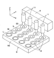
図13において、部品実装装置50のやはりY方向奥側で上述のトレイ供給部3に隣接した位置には、ノズルステーション8が設けられている。部品13を吸着すべきノズル12は、部品13のサイズやスペックに合わせた適切なノズルを使用することが好ましい。このために、異なるサイズや仕様のノズル12がこのノズルステーション8に準備されている。図15は、ノズルステーション8に配列して準備された各ノズル12を模式的に示している。各ノズル12には図の上方に示す部品実装ヘッド4に装備されたノズルヘッド11がアクセス可能である。図15に示す例においては、4つのノズルヘッド11に対応して、4列に配列されたノズル12が4行分用意されている。図では、Y方向奥側から各行毎に、微小サイズ(SS)、小サイズ(S)、中サイズ(M)、大サイズ(L)の各ノズルがそれぞれ4つずつ4列に配置された状態を示している。但し、この配列は一例を示したものであり、生産目的に応じて任意に変更が可能である。なお、本明細書における配列に関しては、X方向(図の左右方向)の並びを「列」、Y方向(図の前後方向)の並びを「行」と呼ぶものとし、以下、部品、回路形成体の配列に関しても同様に呼ぶものとする。ノズルステーション8に配置された各ノズル12の列間のピッチは、ノズルヘッド11の間隙ピッチと一致している。
【0009】
ノズル交換に際しては、部品実装ヘッド4の4つのノズルヘッド11に取り付けられたノズル12が、同時に交換される。すなわち、ノズルステーション8に移動した部品実装ヘッド4の4つのノズルヘッド11がノズルパレット56に向けて下降し、現在取り付けられているノズル12を元の行(例えば、図のSSの行)に同時に戻す。その後、次に装着すべきノズル12の行(例えば、図のMの行)まで移動して、各ノズルヘッド11がその行にある4列のノズル12に下降して同時にこれを取り付ける。このため、ノズルステーション8には、4列、4行の計16個のノズルが配置されているものの、一行ごとのノズル同時交換となるため、4種類(4行)のノズル組み合わせのバリエーションしか持てないことになる。あるいは、これを各ノズルヘッド11毎の任意の組み合わせにかかるノズル12を取り付けようとした場合には、1つのノズルヘッド11ごとに部品実装ヘッド4が移動して位置合わせをする必要があり、ノズル交換に多くの時間を費やすこととなる。
【0010】
【発明が解決しようとする諜題】
以上のように、従来技術による部品実装装置50には幾つかの問題があった。部品実装ヘッドに装着された複数のノズルヘッドは固定されたままであり、したがってノズルヘッドの間隙ピッチも固定されていた。このため、部品を吸着する際に、各ノズルヘッドの間隙ピッチが部品供給部における各部品間の間隙ピッチとたまたま一致している場合は良いが、僅かでも両ピッチ間に相違があった場合には各ヘッドによる部品の同時吸着ができなかった。同時吸着ができない場合、部品実装ヘッドに装着された各ノズルヘッド毎に位置決めをして部品吸着をする必要があり、多くの時間を費やすこととなる。このため、折角の複数ヘッドを備えていても、生産性を改善する効果が損なわれていた。
【0011】
同様に、複数の各ノズルの間隙ピッチが、回路形成体における部品の実装ピッチと僅かでも一致していない場合には、各ノズルごとに、部品実装ヘッドが移動して回路形成体の所定の実装位置にノズルを位置合わせする必要があり、これも多くの時間を必要とし、複数ノズルを備えることの効果が損なわれていた。多面取り回路形成体へ部品実装する場合においても、この面取りのパターンピッチが先の各ノズルヘッドの間隙ピッチと一致していない場合にも、同様な問題があった。
【0012】
次に、ノズル交換に際しては、部品実装ヘッド4に各ノズルヘッド11が固定されているため、ノズルステーション8のノズルパレット56に設けられた一行ごとの同時取替えしかできず、ノズルの組み合わせバリエーションには極端な制約があった。あるいは、各ノズルヘッド11に対して個別のノズル12を任意に選択させようとした場合には、部品実装ヘッド4が各ノズルヘッド11ごとに、旧ノズル12の返却と、新ノズル12の取り出しのため、ノズルパレット56上を移動する必要があり、多くの工数を要し、生産効率の低下を招いていた。
【0013】
さらに、従来では、部品実装ヘッドの複数のノズルヘッドの数や間隙ピッチに対し、部品供給部(トレイ供給部を含む)における部品の配列数と部品の配列ピッチ、多面取り回路形成体の面取り数や面取りのパターンピッチなどがうまく整合された設計となっておらず、部品実装システム全体として見た場合、複数ノズルを装着することによる生産効率の改善メリットを十分有効に生かし切る部品実装方法とはなっていなかった。
【0014】
したがって、本発明は、以上のような従来技術による問題点を解消し、複数ノズルを装着する部品実装装置の利点を生かして複数部品の同時吸着、複数部品の同時実装、多様な組み合わせにかかるノズルの同時変換を可能とし、タクトロスとなる要因を極力排除して生産効率を高めることができる部品実装装置、並びに部品実装方法を提供することを目的としている。
【0015】
【課題を解決するための手段】
本発明は、前記のような課題を、複数のノズルヘッドが前記部品実装ヘッドに対して、回路形成体の部品実装面に略平行な平面上を各々独立して移動可能に保持する機構を備えていることなどの対応により解決しようとするものであり、具体的には以下の内容を含む。
【0016】
すなわち、請求項1に記載の本発明は、部品供給部から部品を吸着して取り出し、当該部品を回路形成体の所定位置に実装する複数のノズルヘッドを有する部品実装ヘッドを備えた部品実装装置であって、前記複数のノズルヘッドが、前記回路形成体の部品実装面に略平行な平面を、前記部品実装ヘッドに対して各々独立して移動可能に保持する機構を備え、前記複数のノズルヘッドが配列された方向をX方向、前記複数のノズルヘッドが移動可能な平面内にて前記X方向と直交する方向をY方向としたとき、前記複数のノズルヘッドの各々を前記部品実装ヘッドに対してX方向に独立して移動させる第1の移動手段と、前記第1の移動手段をY方向に独立して移動させる第2の移動手段との双方からなる前記複数のノズルヘッドを移動可能に保持する機構を、各ノズルヘッドが個別に備えていることを特徴とする部品実装装置に関する。複数のノズルヘッドが独立移動可能とすることで、部品の同時吸着、同時実装を可能にするものである。
【0018】
請求項2に記載の本発明にかかる部品実装装置は、前記第1の移動手段と前記第2の移動手段との双方が、サーボモータ及びボールねじにより駆動されるものであることを特徴としている。
【0019】
請求項3に記載の本発明にかかる部品実装装置は、前記第1の移動手段と前記第2の移動手段とのいずれか一方、もしくは双方が、リニアモータにより駆動されるものであることを特徴としている。
【0020】
請求項4に記載の本発明にかかる部品実装装置は、前記部品実装装置が、複数のノズルを収納するノズルステーションを更に備え、前記ノズルステーションに収納されたノズルが前記X方向とY方向との碁盤状に配置され、前記複数のノズルヘッドによるノズル交換時には、X方向に沿っては各ノズルヘッドが各ノズルに対応した位置に位置決めされ、Y方向に沿っては各ノズルヘッドが任意の行のノズルにアクセスし、前記複数のノズルヘッドが同時にノズル交換できることを特徴としている。複数のノズルヘッドに取り付けられるノズルの組み合わせバリエーションの増加を図るものである。
【0025】
請求項5に記載の本発明にかかる部品実装装置は、複数のノズルヘッドの間隙ピッチを調整することにより、前記部品供給部における部品の同時吸着、又は前記回路形成体への部品の同時実装のいずれか一方、もしくは双方を可能とすることを特徴としている。
【0026】
請求項6に記載の本発明にかかる部品実装装置は、前記部品供給部における部品の同時吸着が、トレイパレットに部品を配列して供給するトレイ供給部からの直接同時吸着するものであることを特徴としている。従来技術にある部品の移載による無駄を排除するものである。
【0036】
【発明の実施の形態】
本発明にかかる第1の実施の形態の部品実装装置につき、図面を参照して説明する。図1は、本実施の形態にかかる部品実装装置1の概観を示している。図において、従来技術で説明したものと同一構成要素にかかるものに対しては同一の符号を付している。本実施の形態にかかる部品実装装置1は、電子部品などの実装すべき部品を供給するパーツカセット方式の部品供給装置19からなる部品供給部2、及びトレイ方式の部品供給装置からなるトレイ供給部3と、両供給部2、3から部品を取り出して回路形成体14に実装する複数のノズルヘッド11を備えた部品実装ヘッド4と、部品実装ヘッド4を所定位置に搬送するXYロボット5と、部品実装ヘッド4に保持された部品13の保持状態を撮像して認識する部品認識装置6と、部品実装装置1に回路形成体14を搬送して保持する回路形成体保持装置7と、多種類の部品に応じた吸着用のノズル12を用意するノズルステーション8と、部品実装装置1全体の動作を制御する制御装置9とを主な構成要素としている。以上の構成は、図13を使用して説明した従来技術による部品実装装置と同様である。
【0037】
本実施の形態にかかる部品実装装置1においては、部品実装ヘッド4に装着された複数のノズルヘッド11の各々が、部品実装ヘッド4に対してそれぞれ独立して移動可能に装着されている。図2はその詳細を示している。図において、部品実装ヘッド4には、図示の例では4つのノズルヘッド11a、11b、11c、11dが装着されており、各ノズルヘッドにはそれぞれノズル12a、12b、12c、12dが取り付けられている。そして、各ノズルは、部品13a、13b、13c、13dをそれぞれ吸着している。ここでは、特定のノズルヘッド、ノズル、部品を説明する場合を除き、総称としては一般にノズルヘッド11、ノズル12、部品13と呼ぶものとする。各ノズルヘッド11は、矢印で示すように、部品実装ヘッド4に対してそれぞれ図のX方向及びY方向に独立して移動可能な構造となっている。ここで、X方向は、ノズルヘッド11が配列された方向であり、Y方向は、前記X方向に直交する方向である。
【0038】
各ノズルヘッドの可動構造につき、図3の拡大図を参照して説明する。図3は、部品実装ヘッド4に装着された1つのノズルヘッド11のみを取り出して表示した斜視図である。図3において、ノズルヘッド11には、ノズル12が取り付けられ、ノズル12はVCM(ボイスコイルモータ)15によって昇降駆動が可能である。このノズル12は、吸着した部品の傾斜角を補正するため、図示しないサーボモータの駆動により、ベルトを介して図のZ軸を中心とした回転(θ回転)が可能である。従来技術においては、ノズルヘッド11は部品実装ヘッド4(図2参照)に固定されていた。本実施の形態においては、図のX方向、Y方向にそれぞれ移動可能な構造を介して部品実装ヘッド4に取り付けられている。
【0039】
この内、ノズルヘッド11のX方向の移動は、ノズルヘッド11をX方向に移動可能に固定する固定プレート21に取り付けられた正逆回転可能なサーボモータ16の駆動により、ボールねじ17を介してノズルヘッド11がリニアガイド18上を移動するよう構成されている。これに対してノズルヘッド11のY方向の移動は、以下のように構成されている。ノズルヘッド11を固定する固定プレート21に取り付けられた4本のスライドシャフト22が、部品実装ヘッド4に固定される支持プレート23に設けられた4つの貫通孔24に、それぞれY方向にスライド可能に嵌装されている。支持プレート23に固定された正逆回転可能なサーボモータ26によりボールねじ27を回転することによって固定プレート21がY方向に駆動される。この固定プレート21の駆動によって、固定プレート21に取り付けられたノズルヘッド11もY方向に駆動される。
【0040】
各ノズルヘッド11には、以上のような移動可能に保持する構造が個別に設けられている。各ノズルヘッド11が部品実装ヘッド4に対してX方向、及びY方向に移動可能であることは、各ノズルヘッド11が、部品実装がされる回路形成体14(図1参照)の実装面に対して略平行な平面上を移動可能であることを意味する。なお、上述の各ノズルヘッド11のX方向、及びY方向の駆動は、ボールねじ17、27を介した駆動のものに限定されるものではなく、例えばリニアモータによる駆動であってもよい。また、本実施の形態では各ノズルヘッド11がX方向及びY方向共に移動可能な機構を備える好ましい形態となっているが、目的に応じていずれか一方向のみを移動可能とすることも勿論可能である。
【0041】
図1に戻って、以上の構成にかかる本実施の形態にかかる部品実装装置1の動作を説明する。まず、電子回路基板などの回路形成体14が回路形成体保持装置7に搬入される。部品実装ヘッド4は、XYロボット5により、部品13を供給する部品供給部2に位置決めされる。部品実装ヘッド4の各ノズルヘッド11は、各ノズル12によって同時に部品13が吸着できるよう、各ノズル12の吸着位置調整を行う。吸着位置調整が行われた各ノズル12は、部品供給部2の部品13に向かって下降し、4本のノズルで同時に部品13の吸着動作を行う。
【0042】
次に、各ノズル12により同時吸着された部品13は、XYロボット5による部品実装ヘッド4の移動により、部品認識装置6上に位置決めされる。そして、部品認識装置6の認識結果に応じて、各ノズル12の基準点と部品13の基準点とのずれ量が算出される。本実施の形態にかかる部品実装装置1においては、各ノズルヘッド11が独立してX方向、Y方向に移動可能であるため、各ノズルヘッド11毎に位置補正が可能である。部品実装ヘッド4が回路形成体14に対向する所定位置まで移動すると、各ノズル12は、制御装置9の指令に基づいてそれぞれ独立して位置補正が加えられ、各ノズル12に吸着された部品13全てが回路形成体14に同時に実装される。従来技術では、各ノズル11毎の位置補正を部品実装ヘッド4が移動して個別に行い、順次実装していた動作を、前記独立した位置補正によって同時実装を行うことができ、大幅な生産効率の改善をもたらす。また、各ノズル12が独立して移動可能であることから、例えば回路形成体14における多面取りのピッチであるパターンピッチがノズル12の間隙ピッチと一致していなくとも、ノズル12が独立して移動できる許容範囲である限り、同時実装が可能である。なお、個々の実装部品13に対する位置決めに関してのプログラムは、入力操作部10により行うことができる。
【0043】
図1において、本実施の形態にかかる部品実装装置1のトレイ供給部3においては、図14を参照して説明した従来技術による部品実装装置50に示す移載ノズル51、及びこれに関連した吸着パレット52、移載軸53が除かれている。この概要を、図4を参照して説明する。図において、実装すべき部品13を収納した所定のトレイパレット31が、部品実装ヘッド4の各ノズル12が吸着動作できる位置までトレイ本体部32から引き出される。次に、部品実装ヘッド4は、トレイパレット31の吸着位置に位置決めされ、各ノズルヘッド11からノズル12が下降して所定の部品13を同時に吸着する。
【0044】
本実施の形態においては、上述のように、部品実装ヘッド4に装着された図示の4つのノズルヘッド11は、単独で移動可能である。したがって、部品実装ヘッド4がトレイパレット31に対向する位置に到着するまでの間に、各ノズルヘッド11の間隙ピッチが、トレイパレット31の同一列に配列された部品13の間隙ピッチと等しくなるよう調整される。これによって、各ノズル12による部品13の同時吸着が可能となり、従来技術による移載ノズル51を利用した部品の置き換えに要する手間を省くことができ、生産性を大幅に改善することができる。
【0045】
なお、図4に示すように、トレイパレット31の一行に配列できる部品13の数を、ノズルヘッド11の数の整数倍(図の例では、ノズルヘッド11の4つに対して、部品はその2倍の8つを配列)となるよう設計することにより、部品実装ヘッド4の数回の部品吸着によって丁度一行分の全ての部品を使い切ることができる。これにより、部品吸着時におけるノズル12の一部が半端となってあまりが生ずることもなく、生産性を改善することができる。この内容に関しては更に後述する。
【0046】
次に、本実施の形態にかかる部品実装装置1では、独立して移動可能な複数のノズル12を備えた部品実装ヘッド4を利用することにより、使用されるノズル12の組み合わせバリエーション数を大幅に増やしている。図5は、図1に示す部品実装装置1のノズルステーション8におけるノズル交換動作の概要を示している。図5(a)は、部品実装ヘッド4に装着された各ノズルヘッド11がノズルステーション8に移動し、取り付けられている各ノズル12をノズルパレット56の元の位置に返却する状況を示している。図示する例においては、図の左から順に、ノズルヘッド11aにはLノズル、ノズルヘッド11bにはMノズル、ノズルヘッド11cにはSノズル、ノズルヘッド11dにはSSノズルがそれぞれ取り付けられている。各ノズルヘッド11は、図に示すY方向に各個に移動可能であることから、部品実装ヘッド4が個別に移動するまでもなく、各ノズルヘッド11がそれぞれ矢印で示すようにY方向に所定量移動し、取り付けていたノズル12を所定の場所に同時に返却することができる。
【0047】
その後、図5bに示すように、次に吸着すべき部品に適したノズル12を取り付けるべく、各ノズルヘッド11は、同じくY方向に所定量移動し、必要なノズル12にアクセスして、全てのノズルヘッド11で同時に所定のノズル12を取り付ける。図示の例では、ノズルヘッド11aがsノズル、ノズルヘッド11bがLノズル、ノズルヘッド11cがSSノズル、そしてノズルヘッド11dがMノズルを取り付ける様子を示している。この間、部品実装ヘッド4の移動は不要である。
【0048】
このように、各ノズルヘッド11におけるノズル12の選択を任意に行うことができ、かつその取り付けを全ノズル同時に行うことができる。従来技術によるものでは、同時に変更できるのは同一行にあるノズルの組み合わせに限定されていた。したがって、本実施の形態によれば、従来のものに比べて4倍のノズルの組み合わせバリエーションを得ることができる。あるいは、従来技術によるもので任意のノズル12を選択する場合には、部品実装ヘッド4が各ノズルヘッド11ごとに、その取り付けるべきノズルの位置まで移動する必要があった。したがって、本実施の形態によれば、従来のものに比べて1/4のノズル交換時間で任意に選択されたノズルの同時取替えが可能となる。
【0049】
以上、本実施の形態にかかる部品実装装置の特性につき説明してきたが、以上の説明の中に含まれる、i)複数のノズルによる同時部品実装、ii)複数のノズルによるトレイ供給部からの直接の部品同時吸着、iii)複数のノズルによる任意の組み合わせパターンの同時ノズル交換の各々は、i)、ii)、iii)の全てを合わせて同時に実施される必然性はなく、必要に応じていずれか1つもしくは2つの組み合わせを個別に実施することであっても勿論よい。その場合においては、上述の各ノズルを可動させる構造において、上記のii)のみを実施する場合にはノズルヘッド11のX方向のみの可動構造を備えておればよく、また、前記のiii)のみを実施する場合にはY方向のみの可動構造を備えておればよい。上記のi)を実施する場合には、図1、図2に示すようなX、Y両方向への可動機構であることが望ましい。
【0050】
次に、本発明にかかる第2の実施の形態の部品実装装置につき、図面を参照して説明する。図6は、本実施の形態にかかる部品実装装置の部品実装ヘッド34、及びノズルヘッド36を示している。従来技術によれば、上述のように、複数ノズルヘッド11の間隙ピッチが多面取りの回路形成体14の面取りのパターンピッチと異なるために、同時実装ができない場合がある。あるいは、複数ノズルヘッド11の間隙ピッチがトレイ供給部3に配列された部品13の間隙ピッチと異なるため、直接同時吸着できない場合がある。本実施の形態にかかる部品実装装置では、部品実装ヘッド34に複数のノズルヘッド36を複数位置に着脱自在に装着することができる構造とし、ノズル12の間隙ピッチを変更可能とすることによって前記問題の解決を図っている。
【0051】
図6(a)において、部品実装ヘッド34には、ノズルヘッド36が取り付け可能な取り付けステーション37が等間隔で9つ用意されている。ノズルヘッド36は、各取り付けステーション37の任意の位置に、設計上許容できる任意の数を装着することができる。例えば、取り付けステーション37の各間隙ピッチが10mmとすると、図6(a)に示す例では、ノズル12の間隙ピッチが20mmとなる4つのノズルヘッド36が取り付けられている。この状態で、部品の配列ピッチが20mmとなるトレイ供給部3から部品を同時吸着し、多面取りのパターンピッチが20mmとなる回路形成体14に同時実装するものとすれば、当該部品実装装置の生産効率を高めることができる。
【0052】
図6(b)に示す例では、ノズル12の間隙ピッチは10mmとなり、トレイ供給部3の部品の配列ピッチが10mmである場合、回路形成体14の多面取りのパターンピッチが10mmである場合に、それぞれ同時実装、又は同時吸着が可能となる。更に、回路形成体14の部品実装におけるパターンに応じて、図7(a)に示すような変則的なノズルヘッド36の配列も可能である。また、図7(b)に示すように、より多くのノズル36を使用して部品の同時実装、もしくは部品の同時吸着を可能とし、生産効率をより一層高めることもできる。なお、上述の取り付けステーションの間隙ピッチ、あるいは取り付きステーションの数は、それぞれ単なる一例であり、生産ニーズに合わせ、設計の許容範囲においていずれも任意に選択することができる。また、取り付けステーション37の間隙ピッチを均等とせず、必要に応じて任意に間隙幅に設定するものとしてもよい。この場合、隣接する前記取り付けステーション37の間隙ピッチを、ノズルヘッド36の径寸法などによる物理的な最小間隙ピッチよりも更に小さいピッチとすることであってもよい。
【0053】
なお、各取り付けステーション37には、ノズルヘッド36が固定できるよう位置決めピンが設けられているが、その他にもノズル12の昇降やθ回転が可能となるよう、エア供給部、電源接続ターミナルなどが設けられており、固定されたノズルヘッド11は特別な結線、配管などを要することなく必要な機能を果たすことができるものとし、着脱作業の容易化を図っている。
【0054】
図8は、本実施の形態における代替案を示している。ここでは、ノズルヘッド36が部品実装ヘッド34に対して着脱自在であると同時に、スライド可能に装着される構造となっている。図において、部品実装ヘッド34には、複数のノズルヘッド36が装着可能な取り付けレール38が設けられている。これにより、設計の許容範囲において、任意の数のノズルヘッド36を任意の間隙ピッチで部品実装ヘッド34に取り付けることができる。取り付けられたノズルヘッド38はスライド移動が可能であることから、ノズルヘッド間の間隙ピッチの調整が任意となり、機種切替え毎に回路形成体14のパターンピッチが大きく変動するような生産形態においては特に有利となる。図6、図7に示すような、取り付けステーション37の位置が予め固定された構造に対して、本代替案のようにピッチが任意に選択できることは、各種の生産ニーズに対応できる点で有利となる。但し、本代替案では、ノズルヘッド36を所定位置に固定するための調整時間が追加して必要となる。一方、図6、図7に示すような取り付けステーション37を固定式とした場合には、生産対応の柔軟性に欠ける点はあるものの、構造が簡単となり、コスト的に有利となる。
【0055】
次に、本発明にかかる第3の実施の形態である部品実装方法につき、図面を参照して説明する。従来技術において、複数ノズルヘッドを備えた部品実装装置で部品実装を行う場合、ノズルヘッドの数と回路形成体の面取りの数との間、あるいはノズルヘッドの数と部品供給部の部品配列数との間に整合性がなければ、複数ノズルヘッドの一部に生産に寄与しないノズルが生じたり、あるいは部品の一部の吸着残りや、多面取り回路形成体の一部の未実装が生じたりする。例えば、4つのノズルヘッドを備えた部品実装装置の部品供給部に5つの部品が配列して供給される場合、始めの4つの部品が同時吸着された後には部品1つがあまりとなり、次の吸着時には1つのノズルヘッドのみが使用されることとなって生産効率を低下させる。本明細書において、これら、ノズル、部品、回路形成体などの一部に生産動作の過程で余剰が生じた場合、これらを「あまり」と称するものとする。上述の例では、部品に1つのあまりが生じており、また、4つのノズルに対して3つの多面取り回路形成体に部品実装する場合には、ノズルに1つのあまりが生じることとなる。
【0056】
さらに、複数ノズルを備えた部品実装装置で部品実装を行う場合、ノズルの間隙ピッチと回路形成体の面取りのパターンピッチとの間、もしくはノズルの間隙ピッチと部品供給部における部品の配列ピッチとの間に整合性がなければ、同時実装もしくは同時吸着ができず、部品実装ヘッドがその都度移動して各ノズルにおける実装もしくは吸着のために位置合わせする必要があり、生産効率を低下させる。本実施の形態では、ノズルの数及びピッチと、部品実装にかかわる他の要素の数及びピッチとの関連を、部品実装システム全体の観点から改善し、生産性の向上を図ることができる部品実装方法を提供するものである。
【0057】
まず、図9を参照して、多面取りの回路形成体14の面取り数と、複数のノズル12(もしくは、複数のノズルヘッド11)の数との関係について述べる。図9(a)においては、部品実装ヘッド4に装着されたノズル12の数4に対して、回路形成体14の面取り数は3である。したがって、各ノズル12で同時実装を行うときにノズル12(もしくは、ノズルヘッド11)にあまりが1つ生ずるものとなり、生産上の無駄が生じている。逆に、回路形成体の14の面取り数が5であった場合には、4つのノズル12による同時実装で回路形成体の多面取りの1つがあまりとなり、生産を非効率にする。このような場合には、図9(b)に示すように、回路形成体14の面取りの数と、ノズル12の数とを同一の4つとすれば、ノズル12の側も回路形成体14の側にもあまりが生ずることなく、効率的な部品実装をすることができる。あるいは、回路形成体14の面取り数を、ノズル12の数の整数倍とすることであっても、ノズル12による複数回の同時実装の後には、ノズル12にも回路形成体14にもあまりが生ずることがなく効率的となる。本明細書において、回路形成体の多面取りの数をいう場合には、複数のノズルが配列された方向(図9(a)におけるX方向)の列数をいうものとする。
【0058】
図9(b)示す例において、4列の多面取り回路形成体14aの各区分毎に、□、△、○に示す部品を4つのノズル12により順次効率的に同時実装する状況を示している。各部品間のピッチp1、p2、p3は、いずれもノズルヘッド11の間隙ピッチに一致しており、効率的な同時実装が可能となる。
【0059】
図10に示す例では、回路形成体14bの面取りのパターンピッチが、ノズルヘッド11の間隙ピッチの1/2となっている。このような場合には、まず図10(a)に示すように、ノズル12による実装を1列おきの面を対象に行い、次に、図10(b)に示すように、回路形成体14bの面取りピッチ(ノズル12の間隙の1/2ピッチ)分だけずらして残りの面に実装することにより、同時実装が可能となり、効率的な部品実装を実現できる。図示の例では、回路形成体の面取りの数は8であるが、これが8の倍数であっても、ノズル12及び回路形成体14にあまりが生ずることなく、効率的な生産ができる。
【0060】
一般に、多面取り回路形成体の面取りのパターンピッチをノズルヘッド11の間隙ピッチの1/Nとし、回路形成体の多面取りの列の数をノズルの数のN倍、もしくはNの整数倍とすることにより、ノズル12にも回路形成体14にもあまりが生ずることなく、効率的な実装動作を実現することができる。ここに、Nは、0以外の整数である。
【0061】
更に、図11に示す例では、回路形成体14cの面取りのパターンピッチが、ノズル12の間隙ピッチの2倍となっている。このような場合には、図に示すように、4つのノズルヘッドの内、ノズルヘッド11aとノズルヘッド11c、及びノズルヘッド11bとノズルヘッド11dとの2つを組み合わせて対処することができる。すなわち、これら両組み合わせにかかるノズルヘッド11の間隙ピッチに関しては、回路形成体14bの面取りのパターンピッチと一致している。したがって、ノズルヘッド11a、11cでは同一部品の同時実装が可能となり、同様にノズルヘッド11b、11dにおいても、同一部品の同時実装が可能となる。更には、図11に示すように、回路形成体の単一面に実装される部品13a、13bが別部品であっても、この両部品間の間隙ピッチのそれぞれ(図のp1、p2、p3)をノズルヘッド11の間隙ピッチに一致させ、更に図のY方向の同一レベルに両部品13a、13bほかを配置するような設計とすれば、異なる部品であっても、ノズルヘッド11a、11b、11c、11dによる同時実装が可能となる。
【0062】
一般に、多面取り回路形成体の面取りのパターンピッチをノズルヘッド11の間隙ピッチのM倍とすることにより、複数ノズルを効率的に使用することができ、部品実装の生産性を高めることができる。更に、回路形成体14cの多面取りの単一面内においても、複数ノズルが配列されている方向(図11のX方向)と同一方向に、実装部品をノズル間隙ピッチと同一の間隙ピッチで配列する設計とすることにより、複数ノズルを使用した同時実装の可能性を高めることができ、より効率的となる。ここに、Mは、0以外の整数とする。また、この際の回路形成体の面取りの数は、ノズルヘッド11にも回路形成体14にもあまりが生じない数とすることが生産効率上好ましい。このときの面取り数は、一般に、ノズルヘッドの数をK(整数)とした場合、KとMとの最小公倍数をMで除した値の整数倍となる。例えば、ノズルヘッド数Kが4、ピッチ倍数Mが2とした場合には、面取り数は2の整数倍、ノズルヘッド数Kが6、ピッチ倍数Mが4とした場合には、面取り数は3の整数倍とすることが好ましい。
【0063】
次に、同様な現象をノズルと部品供給部との関係について説明する。例えば図12(a)に示すように、ノズル12を4つ備えた部品実装装置において、部品供給部2に供給される部品13の列の数がZ1からZ11までの11であったとする。4つのノズル12により、図の左側のZ1からZ4までが同時吸着Aで吸着され、以下、同時吸着Bで次のZ5からZ8までが吸着されると、最後には部品供給部に3列が残る。このため、次の同時吸着Cではノズル12に1つのあまりが生じ(あるいは、同時吸着Bの後に部品供給部2に3つのあまりが生じ)、ノズル12に遊びが生じて無駄となる。
【0064】
これを、図12(b)に示すように、部品供給部2における部品12の配列数を、ノズル12の数の整数倍とすることにより、複数回の同時吸着の後にノズル12にあまりが生ずることなく(あるいは、部品供給部2にあまりが生ずることなく)、効率的な部品吸着を可能にし、生産効率を高めることができる。
【0065】
部品を供給する列のピッチが、ノズルの間隙のピッチよりも小さい場合においても、同様な考え方の適用ができる。図12(c)に示すように、例えばノズル12の間隙ピッチ20mmに対して、部品13の配列ピッチを10mmにセットし、ノズル12は一旦同時吸着Aで部品13を1つおきに(Z1、Z3、Z5、Z7)吸着した後、次の同時吸着Bでは部品13の配列ピッチ(ノズル12の間隙ピッチの1/2)分だけ移動して残りの部品13(Z2、Z4、Z6、Z8)を同時吸着することにより、効率的な吸着ができる。この際、部品供給部2の列の数は、ノズル12の偶数倍とすることで部品供給部2とノズル12とにあまりを生ずることなくなり、効率的となる。
【0066】
一般に、部品供給部2の部品13の配列ピッチを、ノズルヘッド11の間隙ピッチの1/Nとし、部品13の列数をノズルの数のN倍、もしくはNの整数倍とすることにより、ノズル12にも部品供給部2にもあまりが生ずることなく、効率的な実装吸着を実現することができる。ここに、Nは、0以外の整数である。なお、ここではパーツカセット方式の部品供給部2を例示しているが、トレイ供給部3においても、全く同様の考え方が適用できる。図4に示した例では、ノズル12の数4つに対して、トレイ供給部3の配列数を8つとしており、ノズルと部品とにあまりが生ずることなく、効率的な同時吸着を可能にしている。なお、逆に部品供給部の部品13の配列ピッチを、ノズルヘッド11の間隙ピッチのN倍とすることも可能ではあるが、この場合にはノズルヘッド11が1/Nの数しか使用できなくなり、必ずしも効率的とは言えない場合もある。但し、部品13の配列ピッチとノズルヘッド11の間隙ピッチとの間に何らの相関関係がない場合に比べては有利となる。
【0067】
図9から図11においては、複数のノズルヘッド11と回路形成体14との関係について、図12においては、複数のノズルヘッド11と部品供給部2、又はトレイ供給部3との関係について示している。部品実装装置においては、ノズルヘッド11が部品供給部2から部品13を吸着して回路形成体14に実装する。すなわち、吸着と実装とが同じ複数のノズルヘッド11を介して行われていることから、上述の効率化の観点からいえば、回路形成体14の面取りのパターンピッチと、部品供給部2、又はトレイ供給部3の配列ピッチとの間においても整合が取れていることが合理的である。本実施の形態では、回路形成体14の面取りのパターンピッチと部品供給部2、又はトレイ供給部3における部品の配列ピッチとを一致させること、もしくは前記パターンピッチと前記配列ピッチの内のいずれか一方がいずれか他方の整数倍とすることにより、効率化を図るものとしている。
【0068】
【発明の効果】
部品実装ヘッドに対して独立して平面状に移動可能な複数のノズルヘッドを備えた本発明にかかる部品実装装置によれば、ノズルヘッドの間隙ピッチを部品供給部における部品の配列ピッチに整合させることにより同時吸着が可能となり、またノズルヘッドの平面状の移動制御により多面取りの回路形成体への同時実装が可能となり、効率的な部品実装を実現することができる。更に、ノズルヘッドのノズル交換時には、従来技術に比べてはるかに多くの組み合わせバリエーションを実現することができ、生産性向上に貢献することができる。
【0069】
また、部品実装ヘッドに対して着脱自在に装着することができる複数のノズルヘッドを備えた本発明にかかる部品実装装置によれば、ノズルヘッドの間隙ピッチを部品供給部における部品の配列ピッチに整合させることにより同時吸着が可能となり、またノズルヘッドの間隙ピッチを回路形成体の多面取りパターンピッチに整合させることにより同時実装が可能となり、効率的な部品実装を実現することができる。
【0070】
そして、部品供給部の部品の配列、複数のノズルヘッド、及び回路形成体の面取りの各相互間において、それぞれのピッチ、及び数に関して整合のとれた設計を行う本発明にかかる部品実装方法によれば、部品、ノズルヘッド、多面取り回路形成体の各要素において、あまりが生ずることなく、各要素を効率的に使用することができ、部品実装の生産性を高めることができる。
【図面の簡単な説明】
【図1】 本発明にかかる実施の形態の部品実装装置の概要を示す斜視図である。
【図2】 図1に示す部品実装装置の部品実装ヘッドを示す詳細斜視図である。
【図3】 図2に示す部品実装ヘッドの部分拡大斜視図である。
【図4】 図1に示す部品実装装置のトレイ供給部を示す詳細斜視図である。
【図5】 図1に示す部品実装装置のノズル交換の状況を示す説明図である。
【図6】 本発明にかかる他の実施の形態の部品実装ヘッドを示す斜視図である。
【図7】 本発明にかかる他の実施の形態の部品実装ヘッドを示す斜視図である。
【図8】 図6に示す部品実装ヘッドの代替案を示す斜視図である。
【図9】 本発明にかかる更に他の実施の形態のノズルヘッドと回路形成体のとの関係を示す説明図である。
【図10】 図9に示す他の適用例を示す説明図である。
【図11】 図9に示す更に他の適用例を示す説明図である。
【図12】 本発明にかかる更に他の実施の形態のノズルヘッドと部品供給部との関係を示す説明図である。
【図13】 従来技術による部品実装装置の概観を示す斜視図である。
【図14】 図13に示す部品実装装置のトレイ供給部を示す詳細斜視図である。
【図15】 図13に示す部品実装装置のノズルステーションを示す詳細斜視図である。
【符号の説明】
1.部品実装装置、 2.部品供給部、 3.トレイ供給部、 4.部品実装ヘッド、 5.XYロボット、 6.部品認識装置、 7.回路形成体保持装置、8.ノズルステーション、 9.制御装置、 11.ノズルヘッド、 12.ノズル、 13.部品、 14.回路形成体、 16.サーボモータ、 17.ボールねじ、 18.リニアガイド、 21.固定プレート、 22.スライドシャフト、 23.支持プレート、 26.サーボモータ、 27.ボールねじ、 31.トレイパレット、 32.トレイ本体部、 34.部品実装ヘッド、36.ノズルヘッド、 37.取り付けステーション、 38.取り付けレール。[0001]
BACKGROUND OF THE INVENTION
The present invention relates to a component mounting apparatus for mounting a component such as an electronic component on a circuit forming body such as an electronic circuit board, and a component mounting method.
[0002]
[Prior art]
A conventional component mounting apparatus will be described with reference to the drawings. FIG. 13 shows an outline of a conventional
[0003]
In FIG. 13, a parts cassette type
[0004]
During the operation of the
[0005]
The
[0006]
On the back side in the Y direction of the
[0007]
In the
[0008]
In FIG. 13, a
[0009]
When replacing the nozzles, the
[0010]
[Problems to be solved by the invention]
As described above, the conventional
[0011]
Similarly, when the gap pitch of each nozzle is slightly inconsistent with the component mounting pitch in the circuit forming body, the component mounting head moves for each nozzle and the predetermined mounting of the circuit forming body is performed. It is necessary to align the nozzle with the position, which also requires a lot of time, and the effect of providing a plurality of nozzles has been impaired. Even when the components are mounted on the multi-chamfer circuit forming body, the same problem occurs when the pattern pitch of the chamfering does not coincide with the gap pitch of each nozzle head.
[0012]
Next, when replacing the nozzle, each
[0013]
Further, conventionally, the number of component arrangements and component arrangement pitches in the component supply unit (including the tray supply unit) and the number of chamfers of the multi-chamfer circuit forming body with respect to the number of nozzle heads and gap pitch of the component mounting head The component mounting method that makes the most of the benefits of improving production efficiency by installing multiple nozzles when viewed as a whole component mounting system is not designed to match the pattern pitch of chamfering and chamfering well. It wasn't.
[0014]
Accordingly, the present invention solves the problems caused by the prior art as described above, and makes use of the advantages of the component mounting apparatus in which a plurality of nozzles are mounted, so that a plurality of components can be suctioned simultaneously, a plurality of components can be mounted simultaneously, and various combinations of nozzles. It is an object of the present invention to provide a component mounting apparatus and a component mounting method capable of simultaneous conversion of the above, and eliminating the factor causing tact loss as much as possible to increase production efficiency.
[0015]
[Means for Solving the Problems]
The present invention is provided with a mechanism for holding the above-described problems so that a plurality of nozzle heads can move independently from each other on a plane substantially parallel to the component mounting surface of the circuit forming body with respect to the component mounting head. In particular, the following contents are included.
[0016]
That is, the present invention described in
[0018]
[0019]
According to a third aspect of the present invention, there is provided the component mounting apparatus according to the third aspect, wherein the first moving unit and the second moving unit. transportation One or both of them are driven by a linear motor.
[0020]
[0025]
[0026]
[0036]
DETAILED DESCRIPTION OF THE INVENTION
A component mounting apparatus according to a first embodiment of the present invention will be described with reference to the drawings. FIG. 1 shows an overview of a
[0037]
In the
[0038]
The movable structure of each nozzle head will be described with reference to the enlarged view of FIG. FIG. 3 is a perspective view in which only one
[0039]
Among these, the movement of the
[0040]
Each
[0041]
Returning to FIG. 1, the operation of the
[0042]
Next, the
[0043]
In FIG. 1, in the
[0044]
In the present embodiment, as shown above, the four nozzle heads 11 shown in the figure mounted on the
[0045]
As shown in FIG. 4, the number of
[0046]
Next, in the
[0047]
Thereafter, as shown in FIG. 5b, each
[0048]
As described above, the
[0049]
As described above, the characteristics of the component mounting apparatus according to the present embodiment have been described. However, i) simultaneous component mounting by a plurality of nozzles included in the above description, ii) direct from the tray supply unit by a plurality of nozzles Iii) Each simultaneous nozzle replacement of any combination pattern by a plurality of nozzles is not necessarily performed simultaneously with all of i), ii), and iii), and any one is necessary. Of course, one or two combinations may be implemented individually. In that case, in the structure in which each nozzle described above is movable, when only the above ii) is carried out, it is only necessary to have a movable structure only in the X direction of the
[0050]
Next, a component mounting apparatus according to a second embodiment of the present invention will be described with reference to the drawings. FIG. 6 shows a
[0051]
In FIG. 6A, the
[0052]
In the example shown in FIG. 6B, the gap pitch between the
[0053]
Each mounting
[0054]
FIG. 8 shows an alternative in the present embodiment. Here, the
[0055]
Next, a component mounting method according to a third embodiment of the present invention will be described with reference to the drawings. In the prior art, when component mounting is performed with a component mounting apparatus having a plurality of nozzle heads, the number of nozzle heads and the number of chamfers of the circuit forming body, or the number of nozzle heads and the number of component arrays in the component supply unit If there is no consistency between the nozzles, there will be nozzles that do not contribute to production in some of the nozzle heads, or some parts that are not picked up, and some parts of the multi-chip circuit formation are not mounted. . For example, when five components are arranged and supplied to a component supply unit of a component mounting apparatus having four nozzle heads, after the first four components are simultaneously sucked, one component becomes too much, and the next sucking is performed. Sometimes only one nozzle head is used, which reduces production efficiency. In this specification, when a surplus occurs in a part of these nozzles, parts, circuit formation bodies, etc. during the production operation, these are referred to as “too much”. In the above-described example, too much is generated in the component, and when the component is mounted on three multi-sided circuit forming bodies for the four nozzles, one of the nozzles is generated.
[0056]
Furthermore, when component mounting is performed with a component mounting apparatus having a plurality of nozzles, the gap pitch between the nozzles and the chamfering pattern pitch of the circuit forming body, or the gap pitch between the nozzles and the arrangement pitch of the components in the component supply unit. If there is no consistency between them, simultaneous mounting or simultaneous suction cannot be performed, and the component mounting head needs to move each time to align for mounting or suction at each nozzle, thus reducing production efficiency. In the present embodiment, component mounting that can improve the productivity by improving the relationship between the number and pitch of nozzles and the number and pitch of other elements involved in component mounting from the viewpoint of the entire component mounting system. A method is provided.
[0057]
First, the relationship between the number of chamfers of the multi-chamfer
[0058]
In the example shown in FIG. 9B, a state in which the components indicated by □, Δ, and ○ are sequentially and efficiently mounted simultaneously by the four
[0059]
In the example shown in FIG. 10, the chamfered pattern pitch of the
[0060]
Generally, the chamfering pattern pitch of the multi-chamfer circuit forming body is 1 / N of the gap pitch of the
[0061]
Furthermore, in the example shown in FIG. 11, the chamfering pattern pitch of the
[0062]
Generally, by setting the chamfering pattern pitch of the multi-chamfer circuit forming body to M times the gap pitch of the
[0063]
Next, a similar phenomenon will be described for the relationship between the nozzle and the component supply unit. For example, as shown in FIG. 12A, in a component mounting apparatus having four
[0064]
As shown in FIG. 12 (b), by setting the number of
[0065]
The same concept can be applied even when the pitch of the row for supplying the parts is smaller than the pitch of the gaps of the nozzles. As shown in FIG. 12 (c), for example, the arrangement pitch of the
[0066]
In general, the arrangement pitch of the
[0067]
9 to FIG. 11 show the relationship between the plurality of nozzle heads 11 and the
[0068]
【The invention's effect】
According to the component mounting apparatus according to the present invention that includes a plurality of nozzle heads that can move independently in a plane with respect to the component mounting head, the gap pitch of the nozzle head is matched with the arrangement pitch of the components in the component supply unit. As a result, simultaneous suction is possible, and the planar movement control of the nozzle head enables simultaneous mounting on a multi-surface circuit forming body, thereby realizing efficient component mounting. Further, when the nozzle of the nozzle head is replaced, far more combination variations can be realized compared to the prior art, which can contribute to productivity improvement.
[0069]
Further, according to the component mounting apparatus according to the present invention including a plurality of nozzle heads that can be detachably mounted on the component mounting head, the gap pitch of the nozzle head is matched to the arrangement pitch of the components in the component supply unit. By doing so, it becomes possible to perform simultaneous suction, and by aligning the gap pitch of the nozzle head with the multi-pattern pattern pitch of the circuit forming body, simultaneous mounting is possible, and efficient component mounting can be realized.
[0070]
According to the component mounting method according to the present invention, the arrangement of components in the component supply unit, the plurality of nozzle heads, and the chamfering of the circuit forming body are designed to be consistent with respect to each pitch and number. For example, each element of the component, the nozzle head, and the multi-cavity circuit forming body can be used efficiently without generating much, and the productivity of component mounting can be improved.
[Brief description of the drawings]
FIG. 1 is a perspective view showing an outline of a component mounting apparatus according to an embodiment of the present invention.
FIG. 2 is a detailed perspective view showing a component mounting head of the component mounting apparatus shown in FIG. 1;
3 is a partially enlarged perspective view of the component mounting head shown in FIG. 2. FIG.
4 is a detailed perspective view showing a tray supply unit of the component mounting apparatus shown in FIG. 1; FIG.
FIG. 5 is an explanatory view showing a state of nozzle replacement in the component mounting apparatus shown in FIG. 1;
FIG. 6 is a perspective view showing a component mounting head according to another embodiment of the present invention.
FIG. 7 is a perspective view showing a component mounting head according to another embodiment of the present invention.
8 is a perspective view showing an alternative to the component mounting head shown in FIG. 6. FIG.
FIG. 9 is an explanatory diagram showing a relationship between a nozzle head and a circuit forming body according to still another embodiment of the present invention.
FIG. 10 is an explanatory diagram showing another application example shown in FIG. 9;
11 is an explanatory diagram showing still another application example shown in FIG. 9. FIG.
FIG. 12 is an explanatory diagram showing a relationship between a nozzle head and a component supply unit according to still another embodiment of the present invention.
FIG. 13 is a perspective view showing an overview of a conventional component mounting apparatus.
14 is a detailed perspective view showing a tray supply unit of the component mounting apparatus shown in FIG. 13;
15 is a detailed perspective view showing a nozzle station of the component mounting apparatus shown in FIG. 13;
[Explanation of symbols]
1. 1. component mounting device; 2. parts supply unit; 3. tray supply unit; 4. component mounting head; XY robot, 6. 6.
Claims (6)
前記複数のノズルヘッドが、前記回路形成体の部品実装面に略平行な平面を、前記部品実装ヘッドに対して各々独立して移動可能に保持する機構を備え、
前記複数のノズルヘッドが配列された方向をX方向、前記複数のノズルヘッドが移動可能な平面内にて前記X方向と直交する方向をY方向としたとき、前記複数のノズルヘッドの各々を前記部品実装ヘッドに対してX方向に独立して移動させる第1の移動手段と、前記第1の移動手段をY方向に独立して移動させる第2の移動手段との双方からなる前記複数のノズルヘッドを移動可能に保持する機構を、各ノズルヘッドが個別に備えていることを特徴とする部品実装装置。In a component mounting apparatus including a component mounting head having a plurality of nozzle heads for sucking and removing a component from a component supply unit and mounting the component at a predetermined position of a circuit forming body.
The plurality of nozzle heads includes a mechanism that holds a plane substantially parallel to a component mounting surface of the circuit forming body so as to be independently movable with respect to the component mounting head.
Wherein the plurality of the direction in which the nozzle head is arranged X-direction, and a direction orthogonal to the X direction in the plurality of nozzle heads are in capable planar moving to the Y direction, each of the previous SL plurality of nozzle heads a first moving means for moving independently in the X-direction with respect to the component mounting head, the first moving means said plurality of consisting both the second moving means for moving independently in the Y direction A component mounting apparatus , wherein each nozzle head is individually provided with a mechanism for holding the nozzle head in a movable manner.
Priority Applications (1)
| Application Number | Priority Date | Filing Date | Title |
|---|---|---|---|
| JP2000374427A JP4514321B2 (en) | 2000-12-08 | 2000-12-08 | Component mounting equipment |
Applications Claiming Priority (1)
| Application Number | Priority Date | Filing Date | Title |
|---|---|---|---|
| JP2000374427A JP4514321B2 (en) | 2000-12-08 | 2000-12-08 | Component mounting equipment |
Publications (2)
| Publication Number | Publication Date |
|---|---|
| JP2002176291A JP2002176291A (en) | 2002-06-21 |
| JP4514321B2 true JP4514321B2 (en) | 2010-07-28 |
Family
ID=18843619
Family Applications (1)
| Application Number | Title | Priority Date | Filing Date |
|---|---|---|---|
| JP2000374427A Expired - Fee Related JP4514321B2 (en) | 2000-12-08 | 2000-12-08 | Component mounting equipment |
Country Status (1)
| Country | Link |
|---|---|
| JP (1) | JP4514321B2 (en) |
Families Citing this family (60)
| Publication number | Priority date | Publication date | Assignee | Title |
|---|---|---|---|---|
| CN100448341C (en) * | 2002-11-21 | 2008-12-31 | 富士机械制造株式会社 | Substrate processing machine, working head of substrate processing machine, substrate processing system, and preparation processing program for using working head of substrate processing machine |
| DE112004001261B4 (en) | 2003-08-04 | 2021-08-12 | Assembléon N.V. | METHOD FOR PICKING UP COMPONENTS WITH THE HELP OF A COMPONENT ASSEMBLY DEVICE |
| JP4763521B2 (en) * | 2006-06-08 | 2011-08-31 | パナソニック株式会社 | Component mounting apparatus, component mounting method, crimping apparatus, and crimping method |
| JP2009059961A (en) * | 2007-08-31 | 2009-03-19 | Toshiba Components Co Ltd | Die bonder device |
| JP5075106B2 (en) * | 2008-12-25 | 2012-11-14 | ヤマハ発動機株式会社 | IC handler |
| JP5106379B2 (en) * | 2008-12-26 | 2012-12-26 | ヤマハ発動機株式会社 | IC handler |
| JP5654745B2 (en) * | 2009-11-30 | 2015-01-14 | 京セラクリスタルデバイス株式会社 | Piezoelectric vibration element mounting device |
| KR101639667B1 (en) * | 2010-08-10 | 2016-07-14 | 한화테크윈 주식회사 | Component mounting apparatus |
| KR101649855B1 (en) * | 2010-11-12 | 2016-08-23 | 한화테크윈 주식회사 | Method for optimizing component mounting sequence with variable pitch head and component mounting device using the same |
| JP5466624B2 (en) * | 2010-12-02 | 2014-04-09 | ヤマハ発動機株式会社 | Mounting machine |
| US8646505B2 (en) | 2011-11-18 | 2014-02-11 | LuxVue Technology Corporation | Micro device transfer head |
| US8349116B1 (en) | 2011-11-18 | 2013-01-08 | LuxVue Technology Corporation | Micro device transfer head heater assembly and method of transferring a micro device |
| US8518204B2 (en) | 2011-11-18 | 2013-08-27 | LuxVue Technology Corporation | Method of fabricating and transferring a micro device and an array of micro devices utilizing an intermediate electrically conductive bonding layer |
| US8573469B2 (en) | 2011-11-18 | 2013-11-05 | LuxVue Technology Corporation | Method of forming a micro LED structure and array of micro LED structures with an electrically insulating layer |
| US8809875B2 (en) | 2011-11-18 | 2014-08-19 | LuxVue Technology Corporation | Micro light emitting diode |
| US9773750B2 (en) | 2012-02-09 | 2017-09-26 | Apple Inc. | Method of transferring and bonding an array of micro devices |
| JP2013168418A (en) * | 2012-02-14 | 2013-08-29 | Hitachi High-Tech Instruments Co Ltd | Component mounting device |
| WO2013140600A1 (en) * | 2012-03-23 | 2013-09-26 | 富士機械製造株式会社 | Device for packaging electronic component |
| US9548332B2 (en) | 2012-04-27 | 2017-01-17 | Apple Inc. | Method of forming a micro LED device with self-aligned metallization stack |
| US9105492B2 (en) | 2012-05-08 | 2015-08-11 | LuxVue Technology Corporation | Compliant micro device transfer head |
| US8415768B1 (en) | 2012-07-06 | 2013-04-09 | LuxVue Technology Corporation | Compliant monopolar micro device transfer head with silicon electrode |
| US8791530B2 (en) | 2012-09-06 | 2014-07-29 | LuxVue Technology Corporation | Compliant micro device transfer head with integrated electrode leads |
| US9162880B2 (en) | 2012-09-07 | 2015-10-20 | LuxVue Technology Corporation | Mass transfer tool |
| US9558721B2 (en) | 2012-10-15 | 2017-01-31 | Apple Inc. | Content-based adaptive refresh schemes for low-power displays |
| US9236815B2 (en) | 2012-12-10 | 2016-01-12 | LuxVue Technology Corporation | Compliant micro device transfer head array with metal electrodes |
| US9217541B2 (en) | 2013-05-14 | 2015-12-22 | LuxVue Technology Corporation | Stabilization structure including shear release posts |
| US9484504B2 (en) | 2013-05-14 | 2016-11-01 | Apple Inc. | Micro LED with wavelength conversion layer |
| JP6134201B2 (en) | 2013-05-22 | 2017-05-24 | ヤマハ発動機株式会社 | Work equipment for printed circuit boards |
| US9136161B2 (en) | 2013-06-04 | 2015-09-15 | LuxVue Technology Corporation | Micro pick up array with compliant contact |
| US8987765B2 (en) | 2013-06-17 | 2015-03-24 | LuxVue Technology Corporation | Reflective bank structure and method for integrating a light emitting device |
| US9111464B2 (en) | 2013-06-18 | 2015-08-18 | LuxVue Technology Corporation | LED display with wavelength conversion layer |
| US8928021B1 (en) | 2013-06-18 | 2015-01-06 | LuxVue Technology Corporation | LED light pipe |
| JP6205191B2 (en) * | 2013-06-28 | 2017-09-27 | Juki株式会社 | Electronic component mounting method and electronic component mounting apparatus |
| US9035279B2 (en) | 2013-07-08 | 2015-05-19 | LuxVue Technology Corporation | Micro device with stabilization post |
| US9296111B2 (en) | 2013-07-22 | 2016-03-29 | LuxVue Technology Corporation | Micro pick up array alignment encoder |
| US10111370B2 (en) | 2013-07-23 | 2018-10-23 | Fuji Corporation | Work machine |
| US9087764B2 (en) | 2013-07-26 | 2015-07-21 | LuxVue Technology Corporation | Adhesive wafer bonding with controlled thickness variation |
| JP6017382B2 (en) * | 2013-07-29 | 2016-11-02 | Towa株式会社 | Device and method for conveying individualized electronic components |
| US9153548B2 (en) | 2013-09-16 | 2015-10-06 | Lux Vue Technology Corporation | Adhesive wafer bonding with sacrificial spacers for controlled thickness variation |
| US9367094B2 (en) | 2013-12-17 | 2016-06-14 | Apple Inc. | Display module and system applications |
| US9768345B2 (en) | 2013-12-20 | 2017-09-19 | Apple Inc. | LED with current injection confinement trench |
| US9450147B2 (en) | 2013-12-27 | 2016-09-20 | Apple Inc. | LED with internally confined current injection area |
| US9583466B2 (en) | 2013-12-27 | 2017-02-28 | Apple Inc. | Etch removal of current distribution layer for LED current confinement |
| US9542638B2 (en) | 2014-02-18 | 2017-01-10 | Apple Inc. | RFID tag and micro chip integration design |
| US9583533B2 (en) | 2014-03-13 | 2017-02-28 | Apple Inc. | LED device with embedded nanowire LEDs |
| US9522468B2 (en) | 2014-05-08 | 2016-12-20 | Apple Inc. | Mass transfer tool manipulator assembly with remote center of compliance |
| US9318475B2 (en) | 2014-05-15 | 2016-04-19 | LuxVue Technology Corporation | Flexible display and method of formation with sacrificial release layer |
| US9741286B2 (en) | 2014-06-03 | 2017-08-22 | Apple Inc. | Interactive display panel with emitting and sensing diodes |
| US9624100B2 (en) | 2014-06-12 | 2017-04-18 | Apple Inc. | Micro pick up array pivot mount with integrated strain sensing elements |
| US9570002B2 (en) | 2014-06-17 | 2017-02-14 | Apple Inc. | Interactive display panel with IR diodes |
| US9425151B2 (en) | 2014-06-17 | 2016-08-23 | Apple Inc. | Compliant electrostatic transfer head with spring support layer |
| US9705432B2 (en) | 2014-09-30 | 2017-07-11 | Apple Inc. | Micro pick up array pivot mount design for strain amplification |
| US9828244B2 (en) | 2014-09-30 | 2017-11-28 | Apple Inc. | Compliant electrostatic transfer head with defined cavity |
| US10555450B2 (en) * | 2014-11-07 | 2020-02-04 | Fuji Corporation | Rotary head type component mounter |
| CN107079617B (en) | 2014-11-11 | 2019-08-06 | 株式会社富士 | The control device of electronic part mounting and data input device to the control device input data |
| US9478583B2 (en) | 2014-12-08 | 2016-10-25 | Apple Inc. | Wearable display having an array of LEDs on a conformable silicon substrate |
| JP6666692B2 (en) * | 2015-11-06 | 2020-03-18 | ヤマハ発動機株式会社 | Component mounting machine, component suction method |
| JP2017212255A (en) * | 2016-05-23 | 2017-11-30 | 株式会社ジェイデバイス | Semiconductor manufacturing device and manufacturing method |
| CN116209153B (en) * | 2023-05-06 | 2023-07-18 | 中创领科(西安)智能科技发展有限公司 | Low-power consumption semiconductor device convenient for circuit board installation |
| CN117098385B (en) * | 2023-10-16 | 2024-01-26 | 深圳市易通自动化设备有限公司 | Material moving mechanism and chip mounter |
Citations (7)
| Publication number | Priority date | Publication date | Assignee | Title |
|---|---|---|---|---|
| JPS62155598A (en) * | 1985-12-27 | 1987-07-10 | 松下電器産業株式会社 | Electronic parts mounting apparatus |
| JPH07302997A (en) * | 1994-04-28 | 1995-11-14 | Sanyo Electric Co Ltd | Automatic mounting apparatus of electronic component |
| JPH09102697A (en) * | 1995-10-03 | 1997-04-15 | Juki Corp | Parts mounting equipment |
| JPH09162598A (en) * | 1995-12-04 | 1997-06-20 | Hitachi Electron Eng Co Ltd | Transferring equipment of ic device |
| JPH09214186A (en) * | 1996-01-31 | 1997-08-15 | Mitsumi Electric Co Ltd | Chip mounter |
| JPH11150396A (en) * | 1997-11-19 | 1999-06-02 | Matsushita Electric Ind Co Ltd | Nozzle replacing method of multiple transfer head of electronic part mounting equipment |
| JP2000114787A (en) * | 1998-09-30 | 2000-04-21 | Tenryu Technics:Kk | Electronic part mounter and mounting method |
-
2000
- 2000-12-08 JP JP2000374427A patent/JP4514321B2/en not_active Expired - Fee Related
Patent Citations (7)
| Publication number | Priority date | Publication date | Assignee | Title |
|---|---|---|---|---|
| JPS62155598A (en) * | 1985-12-27 | 1987-07-10 | 松下電器産業株式会社 | Electronic parts mounting apparatus |
| JPH07302997A (en) * | 1994-04-28 | 1995-11-14 | Sanyo Electric Co Ltd | Automatic mounting apparatus of electronic component |
| JPH09102697A (en) * | 1995-10-03 | 1997-04-15 | Juki Corp | Parts mounting equipment |
| JPH09162598A (en) * | 1995-12-04 | 1997-06-20 | Hitachi Electron Eng Co Ltd | Transferring equipment of ic device |
| JPH09214186A (en) * | 1996-01-31 | 1997-08-15 | Mitsumi Electric Co Ltd | Chip mounter |
| JPH11150396A (en) * | 1997-11-19 | 1999-06-02 | Matsushita Electric Ind Co Ltd | Nozzle replacing method of multiple transfer head of electronic part mounting equipment |
| JP2000114787A (en) * | 1998-09-30 | 2000-04-21 | Tenryu Technics:Kk | Electronic part mounter and mounting method |
Also Published As
| Publication number | Publication date |
|---|---|
| JP2002176291A (en) | 2002-06-21 |
Similar Documents
| Publication | Publication Date | Title |
|---|---|---|
| JP4514321B2 (en) | Component mounting equipment | |
| CN107409486B (en) | Method and apparatus for optimizing component type arrangement | |
| KR100444562B1 (en) | Parts mounting method and device for shortening mounting tact time | |
| JP6300808B2 (en) | On-board working system and feeder transfer method | |
| EP1009211A2 (en) | A surface mount machine concept | |
| JPH09246779A (en) | Method and device for attaching parts | |
| JPH10209679A (en) | Electronic component mounting apparatus | |
| WO2016147390A1 (en) | Component mounting line, and component mounting line setup method | |
| JP4342185B2 (en) | Substrate carrying-in method and substrate production system in mounting line | |
| JP6193994B2 (en) | Component mounter | |
| JP4884349B2 (en) | Component mounting method and component mounting control device | |
| JP4493810B2 (en) | Electronic component mounting method and electronic component mounting apparatus | |
| JPH09312494A (en) | Supply of component to mounting machine | |
| JP4354845B2 (en) | Electronic component mounting device | |
| JP5450338B2 (en) | Electronic component mounting machine | |
| JP4326748B2 (en) | Parts mounting method | |
| JP3165289B2 (en) | Surface mounting machine | |
| JP4152020B2 (en) | Component mounting method and surface mounter | |
| US20060021215A1 (en) | Electronic component mounting apparatus | |
| WO2019234943A1 (en) | Temporary holding area location determination method and temporary holding area location determination device for backup device for backup device | |
| JP3365677B2 (en) | Supply part position setting method for mounting machine | |
| JP7433502B2 (en) | Board production method | |
| JPH02132895A (en) | Setup replacement method of component feeding device and electronic component automatic mounting device | |
| JP2514931B2 (en) | Electronic component mounting device | |
| JPH0370199A (en) | Mounting device and method for electronic component |
Legal Events
| Date | Code | Title | Description |
|---|---|---|---|
| A621 | Written request for application examination |
Free format text: JAPANESE INTERMEDIATE CODE: A621 Effective date: 20071127 |
|
| A131 | Notification of reasons for refusal |
Free format text: JAPANESE INTERMEDIATE CODE: A131 Effective date: 20091117 |
|
| A521 | Written amendment |
Free format text: JAPANESE INTERMEDIATE CODE: A523 Effective date: 20100106 |
|
| A131 | Notification of reasons for refusal |
Free format text: JAPANESE INTERMEDIATE CODE: A131 Effective date: 20100202 |
|
| A521 | Written amendment |
Free format text: JAPANESE INTERMEDIATE CODE: A523 Effective date: 20100325 |
|
| TRDD | Decision of grant or rejection written | ||
| A01 | Written decision to grant a patent or to grant a registration (utility model) |
Free format text: JAPANESE INTERMEDIATE CODE: A01 Effective date: 20100413 |
|
| A01 | Written decision to grant a patent or to grant a registration (utility model) |
Free format text: JAPANESE INTERMEDIATE CODE: A01 |
|
| A61 | First payment of annual fees (during grant procedure) |
Free format text: JAPANESE INTERMEDIATE CODE: A61 Effective date: 20100511 |
|
| R150 | Certificate of patent or registration of utility model |
Free format text: JAPANESE INTERMEDIATE CODE: R150 |
|
| FPAY | Renewal fee payment (event date is renewal date of database) |
Free format text: PAYMENT UNTIL: 20130521 Year of fee payment: 3 |
|
| FPAY | Renewal fee payment (event date is renewal date of database) |
Free format text: PAYMENT UNTIL: 20130521 Year of fee payment: 3 |
|
| LAPS | Cancellation because of no payment of annual fees |