JP4482843B2 - Electric disc brake pad wear detection method and electric disc brake device - Google Patents
Electric disc brake pad wear detection method and electric disc brake device Download PDFInfo
- Publication number
- JP4482843B2 JP4482843B2 JP2000099507A JP2000099507A JP4482843B2 JP 4482843 B2 JP4482843 B2 JP 4482843B2 JP 2000099507 A JP2000099507 A JP 2000099507A JP 2000099507 A JP2000099507 A JP 2000099507A JP 4482843 B2 JP4482843 B2 JP 4482843B2
- Authority
- JP
- Japan
- Prior art keywords
- pad
- piston
- brake
- wear
- wear amount
- Prior art date
- Legal status (The legal status is an assumption and is not a legal conclusion. Google has not performed a legal analysis and makes no representation as to the accuracy of the status listed.)
- Expired - Fee Related
Links
Images


Abstract
Description
【0001】
【発明の属する技術分野】
本発明は、電動モータの回転力によって制動力を発生させる電動ディスクブレーキのパッド摩耗の検出方法及び電動ディスクブレーキ装置に関するものである。
【0002】
【従来の技術】
近時、ブレーキ液を使用せず、電動モータの出力によって制動力を発生させるようにした電動ディスクブレーキが用いられるようになってきた。この電動ディスクブレーキの一例として、本願出願人が提案した特願平11−114232号に示すものがある。この電動ディスクブレーキは、ディスクロータの両側に配置される一対のブレーキパッドと前記ブレーキパッドを押圧するピストンと、電動モータと、該電動モータの回転運動を直線運動に変換して前記ピストンを進退動させるボールランプ機構と、前記ブレーキパッドの摩耗に応じて前記ピストンを前進させるパッド摩耗補償機構とを備え、電動モータによってボールランプ機構を駆動させ、ピストンによってブレーキパッドをディスクロータに押圧して制動力を発生させる。また、パッド摩耗補償機構によってブレーキパッドの摩耗に応じてピストンとボールランプ機構の可動ディスクとの相対位置を調整してパッドの摩耗を補償するようにしている。
【0003】
【発明が解決しようとする課題】
ところで、パッド摩耗の検出は、良好な制動力を確保する等のために、精度高く行えることが望まれている。
しかしながら、上述した従来技術では、ボールランプ機構のロータ回転角に制限があることから、直動方向の変位を大きく取れない。このため、パッド摩耗補償機構によりパッド摩耗を補正するが、上述した従来技術では、モータロータの回転量とパッド摩耗量とが一致しなくなり、モータロータ回転角を用いたパッド摩耗量の監視を適正には行えなかった。
【0004】
なお、油圧ディスクブレーキでは、一般に、パッドの裏金に摩耗センサを取付け、この摩耗センサがディスクロータに接触して接触音を発生することを利用してパッド摩耗を検出していた。また、摩耗センサを取付けていない油圧ディスクブレーキでは、パッド摩耗に伴い、ピストンが進みフルードが減ってリザーバの液残量ワーニングランプが点灯することにより、パッド摩耗を検出するようにしていた。
しかしながら、接触音によりパッド摩耗を検出する上述した油圧ディスクブレーキは、接触音が不快感を招く上、ドライバがこの接触音の意味を理解し得ないことが起こり得るという問題点を有している。また、液残量ワーニングランプの点灯によりパッド摩耗を検出する上述した油圧ディスクブレーキでは、ドライバが当該ランプの点灯の意味を理解し得ないことが起こり得、またフルードを用いない電動ディスクブレーキには適用できないという問題点を有している。
【0005】
本発明は、上記事情に鑑みてなされたものであり、パッドの摩耗量を良好に検出できる電動ディスクブレーキのパッド摩耗の検出方法を提供することを目的とする。
【0006】
【課題を解決するための手段】
請求項1記載の発明は、ディスクロータの両側に配置される一対のブレーキパッドと前記ブレーキパッドを押圧するピストンと、電動モータと、該電動モータの回転運動を直線運動に変換して前記ピストンを進退動させるボールランプ機構と、前記ブレーキパッドの摩耗に応じて前記ピストンを前進させるべく、ブレーキパッドが摩耗した際に、ブレーキパッドとピストンと間に所定のパッドクリアランスが確保されるようにピストンを位置決めして次の制動作動に待機させるパッド摩耗補償機構とを備えた電動ディスクブレーキのパッド摩耗の検出方法において、前記ボールランプ機構のボールの戻り位置に対する制動力を発生するときのピストン位置をピストン制動位置データとして求め、該ピストン制動位置データから予め定められるパッドクリアランス値を減算してパッド摩耗量を得、制動作動に伴い前記パッド摩耗量が得られる毎に、該パッド摩耗量をパッド累計摩耗量に加えることを特徴とする。
また、請求項2記載の発明は、ディスクロータの両側に配置される一対のブレーキパッドと前記ブレーキパッドを押圧するピストンと、電動モータと、該電動モータの回転運動を直線運動に変換して前記ピストンを進退動させるボールランプ機構と、前記ブレーキパッドの摩耗に応じて前記ピストンを前進させるべく、ブレーキパッドが摩耗した際に、ブレーキパッドとピストンと間に所定のパッドクリアランスが確保されるようにピストンを位置決めして次の制動作動に待機させるパッド摩耗補償機構とを備えた電動ディスクブレーキ装置において、前記ボールランプ機構のボールの戻り位置に対する制動力を発生するときのピストン位置をピストン制動位置データとして求め、該ピストン制動位置データから予め定められるパッドクリアランス値を減算してパッド摩耗量を得、制動作動に伴い前記パッド摩耗量が得られる毎に、該パッド摩耗量をパッド累計摩耗量に加えるパッド摩耗検出手段と、該パッド累計摩耗量からパッド残量を算出して該パッド残量を表示する表示器とを設けたことを特徴とする。
さらに、請求項3記載の発明は、ディスクロータの両側に配置される一対のブレーキパッドと前記ブレーキパッドを押圧するピストンと、電動モータと、該電動モータの回転運動を直線運動に変換して前記ピストンを進退動させるボールランプ機構と、前記ブレーキパッドの摩耗に応じて前記ピストンを前進させるべく、ブレーキパッドが摩耗した際に、ブレーキパッドとピストンと間に所定のパッドクリアランスが確保されるようにピストンを位置決めして次の制動作動に待機させるパッド摩耗補償機構とを備えた電動ディスクブレーキ装置において、前記ボールランプ機構のボールの戻り位置に対する制動力を発生するときのピストン位置をピストン制動位置データとして求め、該ピストン制動位置データから予め定められるパッドクリアランス値を減算してパッド摩耗量を得、制動作動に伴い前記パッド摩耗量が得られる毎に、該パッド摩耗量をパッド累計摩耗量に加えるパッド摩耗検出手段と、当該パッド累計摩耗量からパッド残量を算出して該パッド残量が所定のパッド厚さ基準値に達したときに報知する報知手段とを設けたことを特徴とする。
【0007】
【発明の実施の形態】
本発明の一実施の形態を図面に基づいて以下に,説明する。
図1ないし図4に示すように、第2実施形態の電動ディスクブレーキ50は、車輪(図示せず)とともに回転するディスクロータ51の一側(通常は車体に対して内側)にキャリパ本体52が配置されており、キャリパ本体52には、略C字形に形成されてディスクロータ51を跨いで反対側へ延びる爪部53がボルト53A によって一体的に結合されている。ディスクロータ51の両側、すなわち、ディスクロータ51とキャリパ本体52との間および爪部53の先端部との間に、それぞれブレーキパッド54,55が設けられている。ブレーキパッド54,55は、車体側に固定されるキャリヤ56によってディスクロータ51の軸方向に沿って移動可能に支持されて、制動トルクをキャリヤ56で受けるようになっており、また、キャリパ本体52は、キャリヤ56に取付けられたスライドピン57によってディスクロータ51の軸方向に沿って摺動可能に案内されている。
【0008】
爪部53の環状のフランジ部53B が結合されたキャリパ本体52の略円筒状のケース58内には、電動モータ59および回転検出器60が設けられ、ボールランプユニット61が爪部53の環状のフランジ部53B 側から電動モータ59のロータ62内に挿入されている。ケース58の後端部には、カバー63がボルト63A によって取付けられている。
【0009】
電動モータ59は、ケース58の内周部に固定されたステータ64と、ステータ64の内周部に対向させてケース58に滑り軸受65,66によって回転可能、かつ、軸方向に移動可能に支持されたロータ62とを備えている。回転検出器60は、ケース52にボルト67A によって取付けられたレゾルバケース67に固定されたレゾルバステータ68と、レゾルバステータ68に対向させてロータ62に固定されたレゾルバロータ69とを備え、これらの相対回転に基づいてロータ62の回転数(回転速度)検出するものである。カバー63には、電動モータ59および回転検出器60に接続されるコネクタ70およびケーブル71が取付けられており、電動モータ59は、コントローラ(図示せず)からの制御信号(電気信号)に応答してロータ62を所望トルクで所望角度だけ回転させられるようになっている。コネクタ70およびケーブル71は、当該車両のサスペンション装置のアーム、リンク、ナックル、ストラット等の部材との干渉を避けるため、ディスクロータ51の軸方向に対して傾斜されて、その径方向外側へ延ばされている。
【0010】
ボールランプユニット61は、電動モータ59のロータ62の回転運動を直線運動に変換するボールランプ機構72と、ブレーキパッド54を押圧するピストン73と、これらの間に介装される調整ナット74と、ボールランプ機構72の回転を調整ナット74に伝達するリミッタ機構75とを備えている。
【0011】
ボールランプ機構72は、爪部53のフランジ部53B に当接し、ピン76によって回転しないように固定された環状の固定ディスク77と、固定ディスク77に対向させて配置された可動ディスク78と、これらの間に介装されたボール79(鋼球)とから構成されている。可動ディスク78には、固定ディスク77に挿通されてケース58の内部まで延びる円筒部80が一体に形成されている。円筒部80は、ロータ62の内周部にスプライン結合されており、これらのスプライン結合部80A は、軸方向の摺動性、寸法公差および組付性を考慮して回転方向および径方向に所定の遊びが設けられている。
【0012】
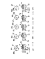
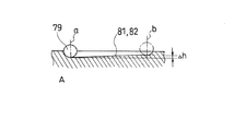
図7に示すように、固定ディスク77および可動ディスク78の互いの対向面には、それぞれ円周方向に沿って円弧状に延びる3つボール溝81,82が形成されている。3つのボール溝81,82は、それぞれ等しく中心角90°の範囲で延ばされて等間隔に配置されている。図8に示すように、各ボール溝81,82は、一端部の最深部aから他端部bの最浅部までΔhの高低差をもって同方向に傾斜されている。また、固定ディスク77の各ボール溝81と可動ディスク78の各ボール溝82とは、原位置において、それぞれ最深部aどうしが対向するように配置され、これらの最深部aの間のそれぞれにボール79が装入されている。これにより、可動ディスク78が固定ディスク77に対して回転すると、ボール79がボール溝81,82内を最浅部b側へ向かって転動して、回転角度に応じて固定ディスク77が可動ディスク78から離間する方向へ軸方向に沿って移動するようになっている。この場合,可動ディスク78がその原位置から時計回りに回転したとき、固定ディスク77が図1中の右方へ移動して爪部53を介してデブレーキパッド54をディスクロータ51へ押圧するようになっている。
【0013】
上述したように、固定ディスク77および可動ディスク78の互いの対向面には、それぞれ円周方向に沿って円弧状に伸びる3つのボール溝81,82が形成され、これらの間にボール79が装入されており、固定ディスク77と可動ディスク78との相対回転によって、3つのボール79がボール溝81,82内を転動して回転角度に応じて固定ディスク77と可動ディスク78とが軸方向に相対移動するようになっている。
【0014】
調整ナット74(パッド摩耗補償機構)は、円筒部83およびその一端部の外側に形成されたフランジ部84からなり、円筒部83が可動ディスク78の円筒部80に挿通され、滑り軸受85によって回転可能に支持され、フランジ部84が可動ディスク78の一端部に当接してスラスト軸受86によって回転可能に支持されている。調整ナット74の円筒部83は、ケース58内のロータ62の内部まで延ばされ、その先端部外周にリミッタ機構75が装着されている。
【0015】
リミッタ機構75は、調整ナット74の円筒部83の先端部外周にリミッタ87およびスプリングホルダ88が回転可能に外嵌され、これらがコイルスプリング89によって互いに連結されている。リミッタ87とスプリングホルダ88とは、所定の範囲で相対回転できるように互いに係合され、コイルスプリング89によって回転方向に対して所定のセット荷重が付与されており、リミッタ87をスプリングホルダ89に対して、コイルスプリング89のセット荷重に抗して時計回り(図1の左方から見て時計回り、以下同じ)に回転できるようになっている。リミッタ87に形成された係合凹部87A が可動ディスク78の円筒部80の端部に形成された係合凸部80B に係合されており、リミッタ87は、円筒部80に対して所定の範囲で相対回転できるようになっている。また、調整ナット74の円筒部の先端部外周には、クラッチスプリング90(コイルスプリング)巻装され、その一端部がスプリングホルダ89に結合されており、クラッチスプリング90は、捩じりによる拡径および縮径によって一方向クラッチとして作用し、スプリングホルダ89の時計回りの回転のみを調整ナット74の円筒部83に伝達するようになっている。
【0016】
ピストン73は、調整ナット74の内周部に形成されたねじ部91に螺合されて、調整ナット74がピストン73に対して時計回りに回転するとブレーキパッド54側へ向かって前進するようになっている。調整ナット74の円筒部83内には、一端がナット92A によってレゾルバケース67に固定された回り止めロッド92が挿入され、回り止めロッド92の他端側は、ピストン73に軸方向に摺動可能に挿入され、かつ、回転を規制するように係合されている。回り止めロッド92の中間部に形成されたフランジ部93と調整ナット74の円筒部83内に形成されたフランジ部94との間に、複数の皿ばね95が介装されており、そのばね力によって調整ナット74が図1中の右方へ付勢されている。そして、ナット92A によって回り止めロッド92の軸方向位置を移動させることにより、調整ナット74への付勢力(皿ばね95のセット荷重)を調整できるようになっている。
【0017】
ボールランプ機構72および調整ナット74およびピストン73には、これらを覆ってボールランプユニット61を一体的にサブアセンブリするケース96が装着されており、ケース96の前端側のフランジ部と調整ナット74のフランジ部84との間に、調整ナット74の回転に対して適度な抵抗を付与するウェーブワッシャ97が介装されている。なお、図中、符号98はピストンブーツ、99はピンブーツである。
さらに、この装置には,コントローラ(図示せず)が設けられており,電動モータ59の駆動制御及びパッド摩耗の検出を後述するように行う。
【0018】
以上のように構成した本実施形態の作用について次に説明する。
【0019】
制動時には、コントローラ(図示せず)からの信号に応じて電動モータ59のロータ62が所定のトルクで時計回りに回転すると、スプライン結合部を80A を介してボールランプ機構72の可動ディスク78が回転し、ボール79がボール溝81,82に沿って転動して可動ディスク78を軸方向に沿ってブレーキパッド54側へ前進させる。この推力がスラスト軸受86を介して調整ナット74に伝達され、さらに、ねじ部91を介してピストン73に伝達されて、一方のブレーキパッド54をディスクロータ51に押圧させ、その反力によってキャリパ本体52がキャリヤ56のスライドピン57に沿って移動して、爪部53が他方のブレーキパッド55をディスクロータ51に押圧させ、電動モータ59のトルクに応じて制動力が発生する。
【0020】
制動解除時には、電動モータ59を逆回転させ、可動ディスク78を反時計回りに元の位置まで回転させると、さらばね95のばね力によって可動ディスク78、調整ナット74およびピストン73が後退し、ブレーキパッド54,55がディスクロータ51から離間して制動が解除される。
【0021】
次に、ブレーキパッド54,55の摩耗の補償について図5および図6を参照して説明する。なお、ピストン73とブレーキパッド54および爪部53とブレーキパッド55の相対位置関係は同様であるから、図5および図6には、ピストン73とブレーキパッド54との関係のみを示す。
【0022】
ブレーキパッド54の摩耗がない場合、または、後述する摩耗の調整が行われた後には、図5に示すように、制動時に、ロータ62の回転によってピストン73が非制動位置(A)からパッドクリアランスCだけ前進してブレーキパッド54がディスクロータ51に当接する制動開始位置(B)へ移動すると、可動ディスク78の円筒部80の係合凸部80B がリミッタ87の係合凹部87A に沿って回転して係合凹部80B の一端部から他端部へ移動する。さらに、ピストン73がブレーキパッド54をディスクロータ51に押圧して制動位置(D)へ移動すると、係合凸部80B がリミッタ87を時計回りに回転させ、その回転力がコイルスプリング89およびクラッチスプリング90を介して調整ナット74に伝達される。このとき、ピストン73がブレーキパッド5を押圧しており、ピストン73と調整ナット74との間のねじ部91に大きな摩擦力が生じているため、コイルスプリング89が撓んで調整ナット74は回転しない。そして、制動解除時に、可動ディスク78の逆回転によってピストン73が非制動位置(A)まで後退する際、係合凸部80B が係合凹部80B の一端部に当接してリミッタ62およびスプリングホルダ88を反時計回りに回転させるが、クラッチスプリング90が拡径して空転するため、ピストン73は回転しない。このようにして、パッドの摩耗は調整されず、一定のパッドクリアランスが維持される。
【0023】
ブレーキパッド54が摩耗した場合、図6に示すように、制動時に、ロータ62の時計回りの回転によってブレーキパッド54が非制動位置(A)からパッドクリアランスCの分だけ位置(B)まで移動し、係合凸部80B が係合凹部87A の一端部から他端部へ移動しても、摩耗分Wによってピストン73はブレーキパッド54を押圧しない。ロータ62がさらに回転すると、可動ディスク78および調整ナット74がディスクロータ51側へ位置(D)まで前進してピストン73がブレーキパッド54をディスクロータ51に当接させる。この間、係合凸部80B がリミッタ87を時計回りに回転させ、その回転力がコイルスプリング89およびクラッチスプリング90を介して調整ナット74に伝達されるが、ピストン73がブレーキパッド54を押圧しておらず、ピストン73と調整ナット74との間のねじ部91に大きな摩擦力が生じていないため、調整ナット74が時計回りに回転してピストン73をブレーキパッド54側へさらに前進させてパッドの摩耗を調整する。
【0024】
そして、ピストン73がブレーキパッド54をディスクロータ51に押圧させる位置(E)まで移動する際には、ピストン73と調整ナット74との間のねじ部91に大きな摩擦力が生じ、コイルスプリング89に撓みが生じて調整ナット74の回転が停止する。そして、制動解除時に、ロータ62の反時計回りの回転よってピストン73が非制動位置(A)まで後退すると、係合凸部80B が係合凹部87A の一端部に当接してリミッタ87を反時計回りに回転させるが、クラッチスプリング90が拡径して空転するため、調整ナット74は回転しない。このようにして、摩耗によって生じた非制動位置におけるブレーキパッド54とピストン73との隙間Wは、W′まで減じることになり、ブレーキパッド54の摩耗分の内の一定の割合だけ1回の動作でピストン73を調整ナット74からブレーキパッド54側へ前進させることができる。これを繰り返すことにより、パッドの摩耗調整を行うことができる。
【0025】
以下、本発明の一実施の形態の電動ディスクブレーキのパッド摩耗の検出方法を図面に基づいて説明する。
【0026】
前記コントローラは、回転検出器60の出力等を利用することにより、次のようにパッド摩耗の検出を行う。その方法について図9ないし図11を参照して以下に,説明する。
【0027】
図11のフローチャートに示すように,まず、ステップS1でボール79がランプ機構72のランプの底に相当する戻り位置A(図8)にあることの検出(後述するステップS2参照)が行われたか否かの判定を行う。
ステップS1でNO(ボール79が戻り位置Aにあることを検出していない)と判定すると、ステップS2に進んで、ボール79が戻り位置Aにあることを、ボール79が戻り位置Aに戻された際、モータの電流値が、図9に示すように大きくなることを利用して検出する。そして、その検出結果を戻り位置データM0としてその値M0(予め設定した基準位置からの距離)とともに記憶手段(図示省略)に記憶する。ボール79が戻り位置Aにあることの検出は、モータ電流をオフすると、図8の右方向へボール79が引かれるようなばねを設けておくことにより行うようにしてもよい。
【0028】
ステップS1でYES (ボール79が戻り位置Aにあることを検出した)と判定すると、ステップS3に進んで、パッドとディスクロータ51の接触位置Bを検出し、その検出結果(前記基準位置からの距離)を接触位置(M1 )〔ピストン制動位置データ〕として記憶手段にその値M1とともに記憶する。接触位置Bの検出は、図10に示すように、モータをランプの図8の右方向へ制御し、電流値が大きくなる点を検出して行う。
なお、制動に伴い、ブレーキパッドが磨耗した場合には、パッド磨耗機構が作動して、上述したようにピストン73がブレーキパッド54,55の磨耗分だけ前進し、ピストン73の非制動位置から制動開始位置(ディスクロータ51にブレーキパッド54,55が当接する位置)までのパッドクリアランスCが確保されるようになっている。このため,接触位置(M1 )の値M1には,戻り位置データM0(基準位置から戻り位置までの距離)及びパッドクリアランスCと共に、ブレーキパッド54,55の磨耗があった場合には,ブレーキパッド54,55の磨耗分が含まれたものになる。
【0029】
ステップS3に続いて、M2=M1−M0の演算をして、中間データM2を求める。中間データM2は、パッドクリアランスCと共に、ブレーキパッド54,55の磨耗があった場合には,ブレーキパッド54,55の磨耗分を含むものになっている(ステップS4)。
【0030】
ステップS4に続いて、中間データM2 から上述したように予め定められたパッドクリアランスCに相当する値M3を減算し、その差分(パッド摩耗量に相当する)M4(n)(M4(n)=M2−M3)を求める(ステップS5)。次に、M4(n)が0より大きいか否かを判定する(ステップS6)。ステップS5でYES(M4(n)が0より大きい。パッド摩耗補償機構が作動したことを示す。)と判定すると、ステップS6に進んで、M4=M4(n-1)+M4(n)の演算を行い、それまでのブレーキパッド54,55の摩耗量M4(n-1)にM4(n)を加算して累計摩耗量M4 を求める(ステップS7)。これらステップS1からステップS7までの処理とコントローラとによりパッド磨耗検出手段を実現している。ステップS7に続いて、ステップS6で得た累計摩耗量M4を図示しないマルチディスプレイコントローラに入力しパッド摩耗量として表示させる(ステップS8)。この場合、パッド摩耗量が予め定めた基準値を超えたような場合にワーニングランプの点灯を行い、パッドの摩耗をドライバに確実に分からせるようにしてもよい。
【0031】
ステップS6でYES (M4(n) が0以下。パッド摩耗補償機構が作動しないことを示す。)と判定すると、ステップS8に進んでパッド摩耗量の表示を行う。
ステップS8に続いて、M4 をM4(n-1)として記憶手段に格納し、次の制動時のステップS7に待機し、図示しないメインルーチンに戻る。なお、ステップS8で初期段階では、M4(n-1)は0に設定されている。
【0032】
上述したように、ブレーキパッド54,55の磨耗があった場合に、パッドクリアランスC及びブレーキパッド54,55の磨耗分を含む中間データM2からパッドクリアランスCに相当する値M3 を減算し、その差分(パッド摩耗量に相当する)M4(n)(M4(n) =M2 −M3 )を求め(ステップS5)、M4 =M4(n-1)+M4(n)の演算を行い、それまでのブレーキパッド54,55の磨耗量(M4(n-1))にM4(n)を加算して累計摩耗量M4 を求め(ステップS7)、それを表示する(ステップS8)ので、パッド摩耗量をリアルタイムで読み取ることができる。本実施の形態では、累計摩耗量M4 を図示しないマルチディスプレイコントローラに入力しパッド摩耗量として表示させる(ステップS8)ので、ドライバがパッド残量を的確に把握することが可能となり、これによりブレーキパッドの交換を良好なタイミングで行うことができる。
【0033】
上記実施の形態では、ステップS8で累計摩耗量M4 を表示する場合を例にしたが、あらかじめブレーキパッドの厚さを記憶手段にセットしておき、制動に伴う摩耗検出毎にパッド残量を演算により求め、このパッド残量を表示器により表示するように構成してもよい。さらに、パッド残量が予め定めたパッド厚さ基準値に達した場合に、このことを警報器などの報知手段によりドライバに迅速に報知できるように構成してもよい。
【0034】
【発明の効果】
本願発明によれば、パッド摩耗量が定量的に分かるため、ドライバがパッド残量を的確に把握することが可能となり、これによりブレーキパッドの交換を良好なタイミングで行うことができる。また、従来技術で行った接触音を発生させずに、パッドの摩耗量を検出できるので、ドライバなどの搭乗者に不快感を与えることがない。
【図面の簡単な説明】
【図1】本発明の一実施形態の電動ディスクブレーキの縦断面図である。
【図2】図1の装置を一部破断して示す側面図である。
【図3】図1の装置を一部破断して示す平面図である。
【図4】図1の装置を一部破断して示す正面図である。
【図5】図1のパッド摩耗補償機構のパッドが摩耗がない場合の作動を示す説明図である。
【図6】図1のパッド摩耗補償機構のパッドが摩耗した場合の作動を示す説明図である。
【図7】図1の装置のボールランプ機構のボール溝の配置を示す正面図である。
【図8】図7のボール溝のC−C線による断面図である。
【図9】図1のボールが戻り位置にある状態を模式的に示す図である。
【図10】図1の電動モータのモータ位置(モータ回転角)と電流との関係を示す図である。
【図11】本発明の一実施の形態のパッド摩耗の検出方法を説明するためのフローチャートである。
【符号の説明】
50 電動ディスクブレーキ
51 ディスクロータ
52 キャリパ本体
53 爪部
54,55 ブレーキパッド
59 電動モータ
62 ロータ
72 ボールランプ機構
73 ピストン
77 固定ディスク
78 可動ディスク
79 ボール[0001]
BACKGROUND OF THE INVENTION
The present invention relates to a method for detecting pad wear of an electric disc brake that generates a braking force by the rotational force of an electric motor. And electric disc brake device It is about.
[0002]
[Prior art]
Recently, electric disc brakes that do not use brake fluid and generate braking force by the output of an electric motor have come to be used. An example of this electric disk brake is shown in Japanese Patent Application No. 11-114232 proposed by the present applicant. The electric disc brake includes a pair of brake pads disposed on both sides of a disc rotor, a piston that presses the brake pad, an electric motor, and a rotary motion of the electric motor that is converted into a linear motion to move the piston forward and backward. And a pad wear compensation mechanism for moving the piston forward in response to wear of the brake pad. The ball ramp mechanism is driven by an electric motor, and the brake pad is pressed against the disc rotor by the piston to apply a braking force. Is generated. Further, the pad wear compensation mechanism adjusts the relative position between the piston and the movable disk of the ball ramp mechanism in accordance with the wear of the brake pad so as to compensate the pad wear.
[0003]
[Problems to be solved by the invention]
By the way, it is desired that the pad wear can be detected with high accuracy in order to ensure a good braking force.
However, in the above-described prior art, since the rotor rotation angle of the ball ramp mechanism is limited, the displacement in the linear motion direction cannot be increased. For this reason, the pad wear compensation mechanism corrects the pad wear. However, in the above-described conventional technology, the rotation amount of the motor rotor and the pad wear amount do not coincide with each other, and monitoring of the pad wear amount using the motor rotor rotation angle is appropriate. I couldn't.
[0004]
In the hydraulic disc brake, generally, a wear sensor is attached to the back metal of the pad, and the wear of the pad is detected by utilizing the fact that this wear sensor contacts the disc rotor and generates a contact sound. Further, in a hydraulic disc brake not equipped with a wear sensor, the pad wear is detected by the advance of the piston as the pad wears, the fluid decreases, and the remaining liquid warning lamp of the reservoir lights up.
However, the above-described hydraulic disc brake that detects pad wear based on contact sound has problems that the contact sound may cause discomfort and the driver may not understand the meaning of the contact sound. . In addition, in the above-described hydraulic disc brake that detects pad wear by lighting the remaining liquid warning lamp, the driver may not be able to understand the meaning of lighting of the lamp, and in an electric disc brake that does not use fluid, It has a problem that it cannot be applied.
[0005]
The present invention has been made in view of the above circumstances, and an object of the present invention is to provide a method for detecting pad wear of an electric disc brake that can satisfactorily detect the amount of wear of the pad.
[0006]
[Means for Solving the Problems]
According to the first aspect of the present invention, a pair of brake pads disposed on both sides of the disk rotor, a piston that presses the brake pad, an electric motor, and a rotary motion of the electric motor is converted into a linear motion to convert the piston. A ball ramp mechanism that moves forward and backward, and the piston moves forward according to wear of the brake pad As much as possible The brake pads are worn When The piston is positioned so that a predetermined pad clearance is secured between the brake pad and the piston, and the next braking operation is awaited. With pad wear compensation mechanism In the method of detecting pad wear of an electric disc brake, a piston position when generating a braking force for the return position of the ball of the ball ramp mechanism is obtained as piston braking position data, and a pad clearance value determined in advance from the piston braking position data The pad wear amount is obtained by subtracting, and the pad wear amount is added to the cumulative pad wear amount each time the pad wear amount is obtained with the braking operation.
According to a second aspect of the present invention, there is provided a pair of brake pads disposed on both sides of the disk rotor, a piston that presses the brake pad, an electric motor, and a rotational motion of the electric motor converted into a linear motion. A ball ramp mechanism that moves the piston forward and backward, and moves the piston forward according to wear of the brake pad As much as possible The brake pads are worn When In the electric disk brake device comprising a pad wear compensation mechanism for positioning the piston so that a predetermined pad clearance is secured between the brake pad and the piston and waiting for the next braking operation, the ball of the ball ramp mechanism The piston position when generating the braking force with respect to the return position is obtained as piston braking position data, and a pad wear amount is obtained by subtracting a predetermined pad clearance value from the piston braking position data. Pad wear detecting means for adding the pad wear amount to the pad cumulative wear amount each time the amount is obtained, and a display for calculating the pad remaining amount from the pad cumulative wear amount and displaying the pad remaining amount are provided. It is characterized by that.
Furthermore, the invention according to claim 3 provides a pair of brake pads disposed on both sides of the disk rotor, a piston that presses the brake pad, an electric motor, and a rotational motion of the electric motor converted into a linear motion, thereby converting the motor into a linear motion. A ball ramp mechanism that moves the piston forward and backward, and moves the piston forward according to wear of the brake pad As much as possible The brake pads are worn When In the electric disk brake device comprising a pad wear compensation mechanism for positioning the piston so that a predetermined pad clearance is secured between the brake pad and the piston and waiting for the next braking operation, the ball of the ball ramp mechanism The piston position when generating the braking force with respect to the return position is obtained as piston braking position data, and a pad wear amount is obtained by subtracting a predetermined pad clearance value from the piston braking position data. A pad wear detecting means for adding the pad wear amount to the pad cumulative wear amount each time the amount is obtained, and calculating the pad remaining amount from the pad cumulative wear amount so that the pad remaining amount becomes a predetermined pad thickness reference value. An informing means for informing when it is reached is provided.
[0007]
DETAILED DESCRIPTION OF THE INVENTION
An embodiment of the present invention will be described below with reference to the drawings.
As shown in FIGS. 1 to 4, the
[0008]
An
[0009]
The
[0010]
The
[0011]
The
[0012]
As shown in FIG. 7, three
[0013]
As described above, on the opposing surfaces of the fixed disk 77 and the
[0014]
Adjustment nut 74 (Pad wear compensation mechanism) Is composed of a
[0015]
In the
[0016]
The
[0017]
The
Further, this apparatus is provided with a controller (not shown), and performs drive control of the
[0018]
Next, the operation of the present embodiment configured as described above will be described.
[0019]
During braking, when the
[0020]
When releasing the brake, when the
[0021]
Next, compensation for wear of the
[0022]
When there is no wear of the
[0023]
When the
[0024]
When the
[0025]
Hereinafter, a pad wear detection method for an electric disc brake according to an embodiment of the present invention will be described with reference to the drawings.
[0026]
The controller uses the output of the
[0027]
As shown in the flowchart of FIG. 11, first, at step S1, it was detected that the
If it is determined NO in step S1 (it is not detected that the
[0028]
If YES in step S1 (it is detected that the
When the brake pads are worn due to braking, the pad wear mechanism is activated and the
[0029]
Following step S3, M 2 = M 1 -M 0 The intermediate data M 2 Ask for. Intermediate data M 2 If the
[0030]
Subsequent to step S4, the value M3 corresponding to the predetermined pad clearance C as described above is subtracted from the intermediate data M2, and the difference (corresponding to the pad wear amount) M4 (n) (M4 (n) = M2-M3) is obtained (step S5). Next, it is determined whether M4 (n) is greater than 0 (step S6). If YES in step S5 (M4 (n) is greater than 0, indicating that the pad wear compensation mechanism has been activated), the process proceeds to step S6 to calculate M4 = M4 (n-1) + M4 (n) Then, M4 (n) is added to the wear amount M4 (n-1) of the
[0031]
YES in step S6 (M 4 (n) Is 0 or less. Indicates that the pad wear compensation mechanism does not operate. ), The process proceeds to step S8 to display the pad wear amount.
Following step S8, M Four M 4 (n-1) Is stored in the storage means, waits for the next braking step S7, and returns to the main routine (not shown). In step S8, in the initial stage, M 4 (n-1) Is set to zero.
[0032]
As described above, when the
[0033]
In the above embodiment, the cumulative wear amount M is determined in step S8. Four In this example, the thickness of the brake pad is set in the storage means in advance, the remaining pad amount is obtained by calculation every time wear is detected during braking, and the remaining pad amount is displayed on the display. You may comprise as follows. Furthermore, when the pad remaining amount reaches a predetermined pad thickness reference value, this may be configured so that this can be quickly notified to the driver by a notification means such as an alarm device.
[0034]
【The invention's effect】
Invention of the present application According to the above, since the pad wear amount is quantitatively known, the driver can accurately grasp the remaining amount of the pad, whereby the brake pad can be replaced with good timing. Further, since the wear amount of the pad can be detected without generating the contact sound performed in the prior art, the driver or other passengers are not uncomfortable.
[Brief description of the drawings]
FIG. 1 is a longitudinal sectional view of an electric disc brake according to an embodiment of the present invention.
FIG. 2 is a side view showing the apparatus of FIG.
FIG. 3 is a plan view showing the apparatus of FIG.
4 is a front view showing the apparatus of FIG. 1 with a part broken away. FIG.
FIG. 5 is an explanatory view showing an operation when the pad wear compensation mechanism of FIG. 1 has no wear.
6 is an explanatory diagram showing an operation when the pad wear compensation mechanism of FIG. 1 is worn. FIG.
7 is a front view showing the arrangement of ball grooves of the ball ramp mechanism of the apparatus of FIG. 1; FIG.
8 is a cross-sectional view taken along line CC of the ball groove in FIG.
FIG. 9 is a diagram schematically showing a state in which the ball of FIG. 1 is in a return position.
10 is a diagram showing a relationship between a motor position (motor rotation angle) and current of the electric motor of FIG.
FIG. 11 is a flowchart for explaining a pad wear detection method according to an embodiment of the present invention;
[Explanation of symbols]
50 Electric disc brake
51 Disc rotor
52 Caliper body
53 Claw
54,55 Brake pads
59 Electric motor
62 Rotor
72 Ball ramp mechanism
73 piston
77 Fixed disk
78 Movable disc
79 balls
Claims (3)
前記ボールランプ機構のボールの戻り位置に対する制動力を発生するときのピストン位置をピストン制動位置データとして求め、該ピストン制動位置データから予め定められるパッドクリアランス値を減算してパッド摩耗量を得、制動作動に伴い前記パッド摩耗量が得られる毎に、該パッド摩耗量をパッド累計摩耗量に加えることを特徴とする電動ディスクブレーキのパッド摩耗の検出方法。A pair of brake pads disposed on both sides of the disk rotor, a piston that presses the brake pad, an electric motor, a ball ramp mechanism that converts the rotational motion of the electric motor into a linear motion, and moves the piston forward and backward, to advance the piston in response to wear of the brake pads, when the brake pads are worn, positions the piston so that a predetermined pad clearance between the brake pads and the piston is secured to the next braking operation In a method for detecting pad wear of an electric disc brake equipped with a pad wear compensation mechanism for waiting,
The piston position when the braking force for the ball return position of the ball ramp mechanism is generated is obtained as piston braking position data, and a pad wear amount is obtained by subtracting a predetermined pad clearance value from the piston braking position data. A pad wear detection method for an electric disc brake, wherein the pad wear amount is added to the pad cumulative wear amount each time the pad wear amount is obtained with operation.
前記ボールランプ機構のボールの戻り位置に対する制動力を発生するときのピストン位置をピストン制動位置データとして求め、該ピストン制動位置データから予め定められるパッドクリアランス値を減算してパッド摩耗量を得、制動作動に伴い前記パッド摩耗量が得られる毎に、該パッド摩耗量をパッド累計摩耗量に加えるパッド摩耗検出手段と、該パッド累計摩耗量からパッド残量を算出して該パッド残量を表示する表示器とを設けたことを特徴とする電動ディスクブレーキ装置。A pair of brake pads disposed on both sides of the disk rotor, a piston that presses the brake pad, an electric motor, a ball ramp mechanism that converts the rotational motion of the electric motor into a linear motion, and moves the piston forward and backward, to advance the piston in response to wear of the brake pads, when the brake pads are worn, positions the piston so that a predetermined pad clearance between the brake pads and the piston is secured to the next braking operation In the electric disk brake device provided with a pad wear compensation mechanism for waiting,
The piston position when the braking force for the ball return position of the ball ramp mechanism is generated is obtained as piston braking position data, and a pad wear amount is obtained by subtracting a predetermined pad clearance value from the piston braking position data. A pad wear detecting means for adding the pad wear amount to the pad cumulative wear amount every time the pad wear amount is obtained with the operation, and a pad remaining amount is calculated from the pad cumulative wear amount and displayed. An electric disc brake device comprising an indicator.
前記ボールランプ機構のボールの戻り位置に対する制動力を発生するときのピストン位置をピストン制動位置データとして求め、該ピストン制動位置データから予め定められるパッドクリアランス値を減算してパッド摩耗量を得、制動作動に伴い前記パッド摩耗量が得られる毎に、該パッド摩耗量をパッド累計摩耗量に加えるパッド摩耗検出手段と、当該パッド累計摩耗量からパッド残量を算出して該パッド残量が所定のパッド厚さ基準値に達したときに報知する報知手段とを設けたことを特徴とする電動ディスクブレーキ装置。A pair of brake pads disposed on both sides of the disk rotor, a piston that presses the brake pad, an electric motor, a ball ramp mechanism that converts the rotational motion of the electric motor into a linear motion, and moves the piston forward and backward, to advance the piston in response to wear of the brake pads, when the brake pads are worn, positions the piston so that a predetermined pad clearance between the brake pads and the piston is secured to the next braking operation In the electric disk brake device provided with a pad wear compensation mechanism for waiting,
The piston position when the braking force for the ball return position of the ball ramp mechanism is generated is obtained as piston braking position data, and a pad wear amount is obtained by subtracting a predetermined pad clearance value from the piston braking position data. Each time the pad wear amount is obtained with the operation, pad wear detecting means for adding the pad wear amount to the pad cumulative wear amount, and the pad remaining amount is calculated from the pad cumulative wear amount. An electric disc brake device comprising: an informing means for informing when a pad thickness reference value is reached.
Priority Applications (1)
| Application Number | Priority Date | Filing Date | Title |
|---|---|---|---|
| JP2000099507A JP4482843B2 (en) | 2000-03-31 | 2000-03-31 | Electric disc brake pad wear detection method and electric disc brake device |
Applications Claiming Priority (1)
| Application Number | Priority Date | Filing Date | Title |
|---|---|---|---|
| JP2000099507A JP4482843B2 (en) | 2000-03-31 | 2000-03-31 | Electric disc brake pad wear detection method and electric disc brake device |
Publications (3)
| Publication Number | Publication Date |
|---|---|
| JP2001280385A JP2001280385A (en) | 2001-10-10 |
| JP2001280385A5 JP2001280385A5 (en) | 2007-04-19 |
| JP4482843B2 true JP4482843B2 (en) | 2010-06-16 |
Family
ID=18613848
Family Applications (1)
| Application Number | Title | Priority Date | Filing Date |
|---|---|---|---|
| JP2000099507A Expired - Fee Related JP4482843B2 (en) | 2000-03-31 | 2000-03-31 | Electric disc brake pad wear detection method and electric disc brake device |
Country Status (1)
| Country | Link |
|---|---|
| JP (1) | JP4482843B2 (en) |
Cited By (2)
| Publication number | Priority date | Publication date | Assignee | Title |
|---|---|---|---|---|
| CN103244585A (en) * | 2012-02-09 | 2013-08-14 | 阿文美驰技术有限责任公司 | Control method to vehicle brake system |
| US9199624B2 (en) | 2012-02-09 | 2015-12-01 | Arvinmeritor Technology, Llc | Method of controlling a brake system of a vehicle |
Families Citing this family (5)
| Publication number | Priority date | Publication date | Assignee | Title |
|---|---|---|---|---|
| EP1985884B1 (en) | 2006-02-08 | 2012-10-24 | Hitachi, Ltd. | Electric brake |
| JP4474432B2 (en) | 2007-03-27 | 2010-06-02 | 日信工業株式会社 | Vehicle disc brake |
| ATE514013T1 (en) * | 2007-09-24 | 2011-07-15 | Knorr Bremse Systeme | DISC BRAKE, ESPECIALLY FOR A COMMERCIAL VEHICLE |
| KR101347701B1 (en) | 2010-05-18 | 2014-01-16 | 주식회사 만도 | Estimation method of brake pad wear |
| CN115158273B (en) * | 2022-07-04 | 2024-04-16 | 中国第一汽车股份有限公司 | Brake friction plate alarming method and device and vehicle |
-
2000
- 2000-03-31 JP JP2000099507A patent/JP4482843B2/en not_active Expired - Fee Related
Cited By (2)
| Publication number | Priority date | Publication date | Assignee | Title |
|---|---|---|---|---|
| CN103244585A (en) * | 2012-02-09 | 2013-08-14 | 阿文美驰技术有限责任公司 | Control method to vehicle brake system |
| US9199624B2 (en) | 2012-02-09 | 2015-12-01 | Arvinmeritor Technology, Llc | Method of controlling a brake system of a vehicle |
Also Published As
| Publication number | Publication date |
|---|---|
| JP2001280385A (en) | 2001-10-10 |
Similar Documents
| Publication | Publication Date | Title |
|---|---|---|
| US9333953B2 (en) | Electric parking brake system | |
| JP5206952B2 (en) | Disc brake device | |
| US6571921B2 (en) | Motor-driven disk brake | |
| JP5614528B2 (en) | Disc brake | |
| WO2013065724A1 (en) | Electric direct-acting actuator | |
| JP4556153B2 (en) | Electric disc brake | |
| JP4482843B2 (en) | Electric disc brake pad wear detection method and electric disc brake device | |
| JP4756230B2 (en) | Electric brake device | |
| WO2019163595A1 (en) | Electric brake and control device | |
| US20220032885A1 (en) | Electric brake, and control device | |
| JP4283077B2 (en) | Brake device | |
| JP4055037B2 (en) | Electric disc brake | |
| JPH11257382A (en) | Motor-operated disk brake | |
| JP3928149B2 (en) | Electric disc brake | |
| JP2021004646A (en) | Disc brake | |
| JP2006105170A (en) | Electric braking device | |
| JP4432004B2 (en) | Electric disc brake | |
| JP4706809B2 (en) | Electric disc brake | |
| JP4253963B2 (en) | Method and apparatus for initial adjustment of pad clearance of electric disc brake | |
| JP7061681B2 (en) | Electric brakes and controls | |
| JP7153579B2 (en) | brake device | |
| JP2007132397A (en) | Electric brake driving device | |
| JP4357385B2 (en) | Electric brake device | |
| JP2004060867A (en) | Electric disc brake and electric brake device | |
| JP2020026240A (en) | Brake system for vehicle |
Legal Events
| Date | Code | Title | Description |
|---|---|---|---|
| A711 | Notification of change in applicant |
Free format text: JAPANESE INTERMEDIATE CODE: A712 Effective date: 20041126 |
|
| A521 | Written amendment |
Free format text: JAPANESE INTERMEDIATE CODE: A523 Effective date: 20070305 |
|
| A621 | Written request for application examination |
Free format text: JAPANESE INTERMEDIATE CODE: A621 Effective date: 20070305 |
|
| A977 | Report on retrieval |
Free format text: JAPANESE INTERMEDIATE CODE: A971007 Effective date: 20090312 |
|
| A131 | Notification of reasons for refusal |
Free format text: JAPANESE INTERMEDIATE CODE: A131 Effective date: 20090701 |
|
| A521 | Written amendment |
Free format text: JAPANESE INTERMEDIATE CODE: A523 Effective date: 20090831 |
|
| A711 | Notification of change in applicant |
Free format text: JAPANESE INTERMEDIATE CODE: A712 Effective date: 20090902 |
|
| RD03 | Notification of appointment of power of attorney |
Free format text: JAPANESE INTERMEDIATE CODE: A7423 Effective date: 20090902 |
|
| A521 | Written amendment |
Free format text: JAPANESE INTERMEDIATE CODE: A523 Effective date: 20090904 |
|
| TRDD | Decision of grant or rejection written | ||
| A01 | Written decision to grant a patent or to grant a registration (utility model) |
Free format text: JAPANESE INTERMEDIATE CODE: A01 Effective date: 20100303 |
|
| A01 | Written decision to grant a patent or to grant a registration (utility model) |
Free format text: JAPANESE INTERMEDIATE CODE: A01 |
|
| A61 | First payment of annual fees (during grant procedure) |
Free format text: JAPANESE INTERMEDIATE CODE: A61 Effective date: 20100311 |
|
| R150 | Certificate of patent or registration of utility model |
Free format text: JAPANESE INTERMEDIATE CODE: R150 |
|
| FPAY | Renewal fee payment (event date is renewal date of database) |
Free format text: PAYMENT UNTIL: 20130402 Year of fee payment: 3 |
|
| FPAY | Renewal fee payment (event date is renewal date of database) |
Free format text: PAYMENT UNTIL: 20130402 Year of fee payment: 3 |
|
| FPAY | Renewal fee payment (event date is renewal date of database) |
Free format text: PAYMENT UNTIL: 20140402 Year of fee payment: 4 |
|
| LAPS | Cancellation because of no payment of annual fees |