JP4055037B2 - Electric disc brake - Google Patents

Electric disc brake Download PDF

Info

Publication number
JP4055037B2
JP4055037B2 JP11423299A JP11423299A JP4055037B2 JP 4055037 B2 JP4055037 B2 JP 4055037B2 JP 11423299 A JP11423299 A JP 11423299A JP 11423299 A JP11423299 A JP 11423299A JP 4055037 B2 JP4055037 B2 JP 4055037B2
Authority
JP
Japan
Prior art keywords
rotor
disk
ball
electric motor
piston
Prior art date
Legal status (The legal status is an assumption and is not a legal conclusion. Google has not performed a legal analysis and makes no representation as to the accuracy of the status listed.)
Expired - Fee Related
Application number
JP11423299A
Other languages
Japanese (ja)
Other versions
JP2000346109A (en
JP2000346109A5 (en
Inventor
拓也 臼井
行雄 大谷
Current Assignee (The listed assignees may be inaccurate. Google has not performed a legal analysis and makes no representation or warranty as to the accuracy of the list.)
Hitachi Ltd
Original Assignee
Hitachi Ltd
Priority date (The priority date is an assumption and is not a legal conclusion. Google has not performed a legal analysis and makes no representation as to the accuracy of the date listed.)
Filing date
Publication date
Application filed by Hitachi Ltd filed Critical Hitachi Ltd
Priority to JP11423299A priority Critical patent/JP4055037B2/en
Priority to US09/539,316 priority patent/US6374958B1/en
Priority to DE10016162A priority patent/DE10016162B4/en
Publication of JP2000346109A publication Critical patent/JP2000346109A/en
Publication of JP2000346109A5 publication Critical patent/JP2000346109A5/ja
Application granted granted Critical
Publication of JP4055037B2 publication Critical patent/JP4055037B2/en
Anticipated expiration legal-status Critical
Expired - Fee Related legal-status Critical Current

Links

Images

Abstract

PROBLEM TO BE SOLVED: To enlarge a servo ratio without causing the generation of bending moment loads, and to reduce drag of brake pads in a motor-operated disc brake. SOLUTION: First and second ball ramp mechanisms 11, 12 and an electric motor 10 are provided in a caliper body 3. The rotation of a rotor 19 of the electric motor 10 is converted into linear motion by the first and second ball ramp mechanisms 11, 12 to uniformly press and release brake pads 5, 6 on and from a disc rotor through a piston 25 and a claw part 4 to generate braking force, and to prevent drag. A power ratio can be expanded by reducing the inclination of ball grooves 22, 23, 29 of the first and second ball ramp mechanisms 11, 12. Further, the generation of bending moment loads can be prevented by arranging the ball grooves 22, 23, 28, 29 along the circumferential directions of a central disc 15, first and second discs 20, 26 at equal intervals.

Description

【0001】
【発明の属する技術分野】
本発明は、電動モータの回転力によって制動力を発生させる電動ディスクブレーキ装置に関するものである。
【0002】
【従来の技術】
例えば自動車等の車両の制動装置として、ブレーキ液を使用せず、電動モータの出力によって制動力を発生させるようにした所謂「ドライブレーキ」装置が知られている。
【0003】
ドライブレーキ装置としては、例えば特開昭60−206766号公報に開示されているように、電動モータの回転運動をボールねじ機構によってピストンの進退動に変換し、ピストンによってブレーキパッドをディスクロータに押圧させることにより、制動力を発生させるようにした電動ディスクブレーキ装置がある。この種の電動ディスクブレーキ装置は、運転者によるブレーキペダル踏力(または変位量)をセンサによって検出し、コントローラによって、この検出に応じて電動モータの回転を制御して、所望の制動力を得るようにしている。
【0004】
また、上記のような電動ディスクブレーキ装置においては、各種センサを用いて、各車輪の回転速度、車両速度、車両加速度、操舵角、車両横加速度等の車両状態を検出し、コントローラによってこれらの検出に基づいて電動モータの回転を制御することにより、倍力制御、アンチロック制御、トラクション制御および車両安定化制御等を比較的簡単に組み込むことができる。
【0005】
【発明が解決しようとする課題】
しかしながら、上記従来のボールねじ機構を利用した電動ディスクブレーキ装置では、次のような問題があった。ピストンの推力を大きくして充分大きな制動力を得るためには、モータの出力を大きくするか、あるいは、ボールねじ機構のリードを小さくして倍力比を大きくする必要がある。ところが、モータの出力を大きくした場合、モータが大型化するとともに、消費電力が大きくなるという問題を生じる。一方、ボールねじのリードを小さくする場合は、ボールの直径によって、小リード化にも限界があるため、充分な効果が得られないという問題があった。
【0006】
そこで、ボールねじ機構のねじ溝を1ピッチ未満とすることにより、ボールの直径よりもリードを小さく設定できるようにして、倍力比の増大を図ることが考えられる。しかしながら、このようにした場合、ねじ溝内でボールが循環しない構造となるので、ボールねじ機構の作動を確保するためには、ねじ溝内にボールを完全に充填せず、ボールが装入されていない領域を設ける必要がある。このため、推力がねじ溝全体に均等に発生しないため、モーメント荷重が発生することになり、これらの支持部の強度を高める必要あり、重量が増大するとともに製造コストも高くなるという問題を生じる。さらに、特殊なねじ構造であるため、加工コストも高くなる。
【0007】
また、上記のような電動ディスクブレーキでは、ボールねじ機構、モータ等の設置スペース上の制約から、一方のブレーキパッドをディスクロータに押圧させ、その反力によってキャリパを移動させて他方のブレーキパッドをディスクロータに押圧させるキャリパ浮動型の構造がとられている。このため、推力発生機構から爪部への推力の伝達経路の剛性を高める必要があり、電動モータのケースが厚肉となって重量が増大するという問題がある
【0008】
本発明は、上記の点に鑑みてなされたものであり、モーメント荷重を増大させることなく、倍力比を大きくすることができ、また、推力伝達経路の剛性を高めることができる電動ディスクブレーキを提供することを目的とする。
【0009】
【課題を解決するための手段】
上記の課題を解決するために、請求項1の発明は、ディスクロータの両側に配置される一対のブレーキパッドと、前記一対のブレーキパッドの一方に対向するピストンと、前記ディスクロータをまたいで前記一対のブレーキパッドの他方に対向する爪部と、ロータを回転させる電動モータと、前記ロータの回転運動を直線運動に変換して前記ピストンを進退動させる機構とを備えた電動ディスクブレーキであって、前記機構は、前記ロータの回転により回転し、かつ、前記ロータに対して軸方向に移動可能となっている部材を有するボールランプ機構であり、該ボールランプ機構と前記ロータとの間には、前記ロータの回転を伝えると共に前記部材の軸方向の移動を可能とするスプライン結合部が設けられていることを特徴とする。
【0010】
このように構成したことにより、ロータの回転運動を直線運動に変換して前記ピストンを進退動させる機構は、前記ロータの回転により回転し、かつ、前記ロータに対して軸方向に移動可能となっている部材を有するボールランプ機構であり、該ボールランプ機構と前記ロータとの間は、前記ロータの回転を伝えるとともに前記部材の軸方向の移動を可能とするスプライン結合部によって連結される。そして、ボールランプ機構に介装されたボールによって均等に推力を伝達することができる。
【0011】
請求項2の発明は、ディスクロータの両側に配置される一対のブレーキパッドと、前記一対のブレーキパッドの一方に対向させてキャリパ本体に設けられたピストンと、前記キャリパ本体に固定され前記ディスクロータをまたいで前記一対のブレーキパッドの他方に対向する爪部と、前記キャリパ本体に設けられた電動モータと、該電動モータのロータの回転運動を直線運動に変換して前記ピストンを進退動させる機構とを備えた電動ディスクブレーキであって、前記機構は、前記ロータの回転により回転し、かつ、前記ロータに対して軸方向に移動可能となっている部材を有するボールランプ機構であり、該ボールランプ機構と前記ロータとの間には、前記ロータの回転を伝えると共に前記部材の軸方向の移動を可能とするスプライン結合部が設けられていることを特徴とする。
【0012】
このように構成したことにより、ロータの回転運動を直線運動に変換して前記ピストンを進退動させる機構は、前記ロータの回転により回転し、かつ、前記ロータに対して軸方向に移動可能となっている部材を有するボールランプ機構であり、該ボールランプ機構と前記ロータとの間は、前記ロータの回転を伝えるとともに前記部材の軸方向の移動を可能とするスプライン結合部によって連結される。そして、ボールランプ機構に介装されたボールによって均等に推力を伝達することができる。
請求項3の発明は、上記請求項2の発明の構成において、前記電動モータは前記キャリパ本体に設けられたケースにロータが軸支され、前記ボールランプ機構は、前記爪部に直接推力を伝達することを特徴とする。
このように構成したことにより、ボールランプ機構の推力を爪部に直接伝達するので、電動モータのケースが制動時の荷重を直接受けることがない。
請求項4の発明は、上記請求項1乃至3のいずれかの構成において、前記ボールランプ機構は、前記ディスクロータと前記電動モータとの間に配置されて前記電動モータに連結された固定ディスクと、前記ディスクロータと前記固定ディスクとの間に配置されて前記ピストンに連結された可動ディスクと、前記可動ディスクと前記固定ディスクとの対向部に形成されたボール溝間に介装されたボールとを備え、前記部材が前記可動ディスクであって、該可動ディスクと前記電動モータのロータとが前記固定ディスクの内側を通してスプライン結合により連結されていることを特徴とする。
このように構成したことにより、固定ディスクおよび可動ディスクのボール溝間に介装されたボールによって均等に推力を伝達することができる。
【0013】
【発明の実施の形態】
以下、本発明の実施形態を図面に基づいて詳細に説明する。
【0014】
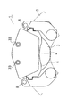
先ず、本発明の参考技術に係る実施形態(以下、第1実施形態という)について図1ないし図12を参照して説明する。図1ないし図3に示すように、第1実施形態の電動ディスクブレーキ1は、車輪と共に回転するディスクロータ2の一側(通常は車体に対して内側)にキャリパ本体3が配置されており、キャリパ本体3には、ディスクロータ2を跨いで反対側まで延びる爪部4が設けられている。ディスクロータ2の両側、すなわち、ディスクロータ2とキャリパ本体3との間および爪部4との間にそれぞれブレーキパッド5,6が設けられている。ブレーキパッド5,6は、車体側に固定されるキャリヤ7によってディスクロータ2の軸方向に沿って移動可能に支持されており、キャリパ本体3は、キャリヤ7によってスライドピン8を介してディスクロータ2の軸方向に沿って移動可能に案内されている。
【0015】
キャリパ本体3の略円筒状のハウジング9内には、電動モータ10、第1ボールランプ機構11、第2ボールランプ機構12、パッド摩耗補償機構13および回転検出器14(例えばレゾルバ)が設けられ、また、円筒部が一体に形成された中央ディスク15(回動ディスク)がボールベアリング16によって回転可能に支持されている。ハウジング5の後端部には、カバー17が装着されている。
【0016】
電動モータ10は、ハウジング9の内周部に固定されたステータ18と、ステータ18の内周部に対向させて中央ディスク15の円筒部15a の外周部に取付けられたロータ19とを備え、コントローラ(図示せず)からの制御信号(電気信号)に応答してロータ19を所望角度だけ回転させることができ、また、所望トルクで回転させられるようになっている。
【0017】
第1ボールランプ機構11は、中央ディスク15と、中央ディスク15の一端面に対向するように設けられて中央ディスク15の円筒部15a 内に挿入される円筒部20aが一体に形成された第1ディスク20(直動ディスク)と、これらの間に介装されたボール21(鋼球)とから構成されている。
【0018】
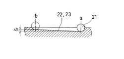
図4に示すように、中央ディスク15および第1ディスク20の互いの対向面には、それぞれ円周方向に沿って円弧状に延びる3つボール溝22,23が形成されている。3つのボール溝22,23は、それぞれ等しい中心角(例えば90°)の範囲で延ばされて等間隔に配置されている。図5に示すように、各ボール溝22,23は、一端部の最深部aから他端部の最浅部bまでΔhの高低差をもって同方向に傾斜されている。また、中央ディスク15の各ボール溝22と第1ディスク20の各ボール溝23とは、原位置において、それぞれ最深部aどうしが対向するように配置され、これらの最深部aの間のそれぞれにボール21が装入されている。これにより、中央ディスク15が第1ディスク20に対して回転すると、ボール21がボール溝22,23内を最浅部b側へ向かって転動して、回転角度に応じて第1ディスク20が中央ディスク15から離間する方向へ軸方向に沿って移動するようになっている。
【0019】
そして、第1ディスク20は、ブレーキパッド5の裏金との間にピン24が挿通されてその回転が規制されており、中央ディスク15がその原位置から時計回り(図1の右方から見て時計回り、以下同じ)に回転したとき、第1ディスク20が図1中の左方へ移動して、第1ディスク20に取付けられたピストン25(後述)を介してブレーキパッド5をディスクロータ2に押圧するようになっている。
【0020】
第2ボールランプ機構12は、中央ディスク15と、中央ディスク15の他端面に対向するように設けられて中央ディスク15および第1ディスク20の周囲を取り囲む円筒部26a が一体的に結合された第2ディスク26と、これらの間に介装されたボール27(鋼球)とから構成されている。
【0021】
図6に示すように、中央ディスク15および第2ディスク26の互いの対向面には、それぞれ円周方向に沿って円弧状に延びる3つボール溝28,29が形成されている。上記第1ボールランプ機構11と同様、3つのボール溝28,29は、それぞれ等しく中心角90°の範囲で延ばされて等間隔に配置されている。図7に示すように、各ボール溝28,29は、一端部の最深部aから他端部bの最浅部までΔhの高低差をもって同方向に傾斜されている。また、中央ディスク15の各ボール溝28と第2ディスク26の各ボール溝29とは、原位置において、それぞれ最深部aどうしが対向するように配置され、これらの最深部aの間のそれぞれにボール27が装入されている。これにより、中央ディスク15が第2ディスク26に対して回転すると、ボール27がボール溝28,29内を最浅部b側へ向かって転動して、回転角度に応じて第2ディスク26が中央ディスク15から離間する方向へ軸方向に沿って移動するようになっている。
【0022】
第2ディスク26の円筒部26a には、爪部4が一体に結合されており、ディスクロータ2の外周側において、爪部4に設けられた開口部31に第1ディスク20から延出されたガイド部32が挿入され、爪部4に螺着された一対のスライドピン33をガイド部32に摺動可能に挿通させて、第1ディスク20と爪部4および第2ディスク26とが、ディスクロータ2の軸方向に沿って相対移動可能に案内され、かつ、これらの相対回転が規制されている。そして、中央ディスク15がその原位置から時計回りに回転したとき、第2ディスク26が図1中の右方へ移動して爪部4を介してブレーキパッド6をディスクロータ2へ押圧するようになっている。なお、第1ディスク20および第2ディスク26は、戻しばね手段(図示せず)によって中央ディスク15へ向かって付勢されている。
【0023】
次に、パッド摩耗補償機構13について説明する。ピストン25は、第1ディスク20の円筒部20a の内周面に形成されたねじ部36(調整ねじ)に螺合されて、反時計回り(図1の右方から見た反時計回り、以下同じ)に回転させるとブレーキパッド5側へ向かって前進するようになっている。ピストン25の後端部には、円柱状のスライド部材37がボルト38によって同心に一体的に取付けられている。第1ディスク20の後端部には、中央ディスク15内に回転可能に挿入された略円筒状の回動部材39が板ばね40によって連結され、回動部材39内に、スライド部材37が一方向クラッチ41を介して嵌合されている。
【0024】
回動部材39は、図8に示すように、板ばね40によって第1ディスク20に回転方向に弾性的に位置決めされており、板ばね40の撓みによって第1ディスク20に対して所定の相対回転が許容されている。一方向クラッチ41は、スライド部材37に対する回動部材39の時計回りの回転のみを許容し、回動部材の反時計の回りの回転に対してはスライド部材37を一体に回転させるようになっている。また、スライド部材37は、スプライン42によって一方向クラッチ41に結合されて、回動部材39および一方向クラッチ41に対して軸方向に相対移動できるようなっている。
【0025】
回動部材39の後端面には、円周方向に沿って所定の中心角の範囲を有する円弧状の係合溝43が形成されている。中央ディスク15内には、回動部材39の後端部に対向する略円筒状のリテーナ44が取付けられている。リテーナ44には、回動部材39の係合溝43に挿入される係合ピン45が取付けられている。そして、中央ディスク15と第1ディスク20とが所定範囲内で相対回転する場合には、係合ピン45が係合溝43内を移動し、中央ディスク15と第1ディスク20との相対回転が所定範囲を越えると、係合ピン45が係合溝43の端部に当接して回動部材39を回転させるようになっており、係合溝43と係合ピン45とで中央ディスク15の所定範囲を越える回転変位のみを伝達する伝達機構を構成している。
【0026】
回転検出器14は、カバー17に取付けられたブラケット46に固定子47が取付つけられ、固定子47に半径方向に対向させてリテーナ44に回転子49が取付けられており、固定子47に対する回転子49の回転に応じて生じる起電力または出力周波数に基づいて中央ディスク15の回転変位すなわち電動モータ10のロータ19の回転変位を検出できるようになっている。
【0027】
以上のように構成した第1実施形態の作用について次に説明する。
【0028】
制動時には、コントローラ(図示せず)からの制御信号を受けて電動モータ10のロータ19すなわち中央ディスク15が時計方向に回転すると、第1および第2ボールランプ機構11,12のボール21,27が、それぞれ溝22,23および溝28,29に沿って転動して、第1ディスク20および第2ディスク26を中央ディスク15の軸方向に関して相反する方向(中央ディスク15から離間する方向)へ移動させ、ピストン25および爪部4によってブレーキパッド5,6をディスクロータ2へ押圧させて制動力を発生させる。そして、ブレーキパッド5,6に作用する回転力をキャリヤ7で支持し、また、キャリパ本体3がキャリヤ7のスライドピン8に沿って移動することにより、ディスクロータ2の両側の摺動面の振れや、制動前におけるディスクロータ2に対する各ブレーキパッド5,6の離間距離(制動時の始動位置となる)の誤差を吸収する。回転検出器14によって検出した中央ディスク15の回転変位に基づいて制動力を制御することができる。
【0029】
中央ディスク15の回転角θと、第1、第2ディスク20,26の軸方向変位δおよびボール21,27の位置との関係を図9ないし図11に示す。図9は、中央ディスク15の回転角θが0°で、第1、第2ディスク20,26の軸方向変位δが0のとき状態を示し、図10は、回転角θ=90°で、軸方向変位δがΔL/2+ΔL/2となった状態を示し、図11は、回転角θが 180°(最大回転角)で、軸方向変位δがΔL+ΔL(最大変位)となった状態を示す。
【0030】
このとき、第1および第2ボールランプ機構11,12は、回転運動を直線運動に変換するが、ボール溝22,23およびボール溝28,29の傾斜を小さくすることにより、回転変位に対するリードを充分小さく設定することができるので、倍力比が大きくすることができ、電動モータ10の出力が小さくてすみ、消費電力の低減およびモータの小型化を図ることができる。
【0031】
また、中央ディスク15と第1、第2ディスク22,23との対向部に、それぞれ3つのボール溝22,23,28,29を円周方向に沿って等間隔に配置したことにより、これらの間で均等に推力が伝達されるので、モーメント荷重が発生することがなく、ブレーキパッド5,6を均等に押圧することができ、安定した制動力を得ることができる。これにより、中央ディスク15および第1、第2ディスク22,23の支持部に作用するモーメント荷重を軽減することができ、必要な強度が小さくてすむので、各部の小型化および軽量化を図ることができる。
【0032】
さらに、第1および第2ボールランプ機構11,12のボール溝22,23とボール溝28,29は、中央ディスク15の両側の同一円周上に配置されており、これらのボール溝22,23間およびボール溝28,29間にそれぞれ介装されたボール21,27は、常時、中央ディスク15のディスク部を挟んで互いに同じ位置に配置されるので(図9ないし図11参照)、制動時にブレーキパッド5,6を押圧した際の反力によってボール21,27に作用する荷重を中央ディスク15のディスク部の各ボール22,23間で挟まれた部分で直接支持することができる。これにより、中央ディスク15には、ボール22,23からの圧縮力のみが作用し、モーメント荷重等が作用することがないので、充分な支持剛性を得ることができ、必要な強度が小さくてすむので、各部の小型化および軽量化を図ることができる。
【0033】
また、ディスクロータ2の両側のブレーキパット5,6を駆動するための第1および第2ボールランプ機構11,12をディスクロータ2に隣接して配置し、その外側に電動モータ10を配置したことにより、第1および第2ボールランプ機構11,12とブレーキパッド5,6との距離を充分近づけることができ、こららの間で推力を伝達する爪部4および円筒部26a の剛性が得やすくなるので、必要な強度が小さくてすみ、各部の小型軽量化を図ることができる。
【0034】
制動解除時には、電動モータ10を逆回転させ、中央ディスク15を反時計回りに元の位置まで回転させると、戻しばね手段のばね力によって第1ディスク20および第2ディスク26とともにピストン25および爪部4が後退して、ディスクロータ2からブレーキパッド5,6が離間して制動が解除される。このとき、第1および第2ボールランプ機構11,12の規制によって、ピストン25および爪部4を同じ距離だけ後退させるので、両側のブレーキパッド5,6をディスクロータ2から均等に離間させることができ、ブレーキパッド5,6の引きずりを軽減することができる。
【0035】
次に、パッド摩耗補償機構13の作用について図12を参照して説明する。ブレーキパッド5,6の摩耗がない場合、または、後述する摩耗の調整が行われた後には、中央ディスク15は、ブレーキパッド5,6の非制動位置と制動位置との間で所定範囲を回動するので、係合ピン45も係合溝43内において非制動位置(図12(A))と制動位置(図12(B))との間で所定範囲を移動する。
【0036】
ブレーキパッド5,6が摩耗すると、制動時に摩耗分だけ中央ディスク15の変位量が増大し、係合ピン45が係合溝43の端部に当接して回動部材39を時計回りに回転させる(図12(C))。このとき、一方向クラッチ41は、スライド部材37に対する回動部材39の時計回りの回転を許容するので、スライド部材37すなわちピストン25は回転しない。その後、制動が解除されて係合ピン45が非制動位置へ移動するとき、回動部材39が反時計回りに元の回転位置まで回転する。このとき、一方向クラッチ41は、スライド部材37と回動部材39との相対回転を阻止するので、回動部材39と共にスライド部材37すなわちピストン25が反時計方向に回転して(図12(D))、調整ねじ部36がブレーキパッド5,6の摩耗分だけピストン25をブレーキパッド5へ向かって前進させる。
【0037】
このようにして、ブレーキパッド5,6の摩耗分だけピストン25を前進させるので、第1および第2ボールランプ機構11,12のストロークが短くても、ブレーキパッド5,6の摩耗を補償することができ、ブレーキパッドの長期間の使用を可能にすることができる。また、従来のキャリパ浮動型の構造では、制動解除時に爪部側のブレーキパッドが戻りにくくなり、ブレーキパッドの引きずりが生じやすいという問題があったが、本実施形態によれば、ブレーキパッドの引きずりを防止することができる。
【0038】
なお、上記実施形態では、中央ディスク15、第1および第2ディスク20,26の対向面に、それぞれ3つのボール溝22,23,28,29を設けているが、これに限らず、ボール溝は、円周方向に等間隔に4つ以上配置することもでき、3つ以上のボール溝によって推力を均等に伝達することができる。
【0039】
次に、本発明の実施形態(以下、第2実施形態という)について図13ないし図18を参照して説明する。
【0040】
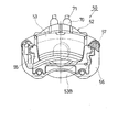
図13ないし図16に示すように、第2実施形態の電動ディスクブレーキ50は、車輪(図示せず)とともに回転するディスクロータ51の一側(通常は車体に対して内側)にキャリパ本体52が配置されており、キャリパ本体52には、略C字形に形成されてディスクロータ51を跨いで反対側へ延びる爪部53がボルト53A によって一体的に結合されている。ディスクロータ51の両側、すなわち、ディスクロータ51とキャリパ本体52との間および爪部53の先端部との間に、それぞれブレーキパッド54,55が設けられている。ブレーキパッド54,55は、車体側に固定されるキャリヤ56によってディスクロータ51の軸方向に沿って移動可能に支持されて、制動トルクをキャリヤ56で受けるようになっており、また、キャリパ本体52は、キャリヤ56に取付けられたスライドピン57によってディスクロータ51の軸方向に沿って摺動可能に案内されている。
【0041】
爪部53の環状のフランジ部53B が結合されたキャリパ本体52の略円筒状のケース58内には、電動モータ59および回転検出器60が設けられ、ボールランプユニット61が爪部53の環状のフランジ部53B 側から電動モータ59のロータ62内に挿入されている。ケース58の後端部には、カバー63がボルト63A によって取付けられている。
【0042】
電動モータ59は、ケース58の内周部に固定されたステータ64と、ステータ64の内周部に対向させてケース58に滑り軸受65,66によって回転可能、かつ、軸方向に移動可能に支持されたロータ62とを備えている。回転検出器60は、ケース52にボルト67A によって取付けられたレゾルバケース67に固定されたレゾルバステータ68と、レゾルバステータ68に対向させてロータ62に固定されたレゾルバロータ69とを備え、これらの相対回転に基づいてロータ62の回転数(回転速度)検出するものである。カバー63には、電動モータ59および回転検出記60に接続されるコネクタ70およびケーブル71が取付けられており、電動モータ59は、コントローラ(図示せず)からの制御信号(電気信号)に応答してロータ62を所望トルクで所望角度だけ回転させられるようになっている。コネクタ70およびケーブル71は、当該車両のサスペンション装置のアーム、リンク、ナックル、ストラット等の部材との干渉を避けるため、ディスクロータ51の軸方向に対して傾斜されて、その径方向外側へ延ばされている。
【0043】
ボールランプユニット61は、電動モータ59のロータ62の回転運動を直線運動に変換するボールランプ機構72と、ブレーキパッド54を押圧するピストン73と、これらの間に介装される調整ナット74と、ボールランプ機構72の回転を調整ナット74に伝達するリミッタ機構75とを備えている。
【0044】
ボールランプ機構72は、爪部53のフランジ部53B に当接し、ピン76によって回転しないように固定された環状の固定ディスク77と、固定ディスク77に対向させて配置された可動ディスク78と、これらの間に介装されたボール79(鋼球)とから構成されている。可動ディスク78には、固定ディスク77に挿通されてケース58の内部まで延びる円筒部80が一体に形成されている。円筒部80は、ロータ62の内周部にスプライン結合されており、これらのスプライン結合部80A は、軸方向の摺動性、寸法公差および組付性を考慮して回転方向および径方向に所定の遊びが設けられている。
【0045】
上記第1実施形態の第2ボールランプ機構と同様に、固定ディスク77および可動ディスク78の互いの対向面には、それぞれ円周方向に沿って円弧状に伸びる3つのボール溝81,82が形成され、これらの間にボール79が装入されており、固定ディスク77と可動ディスク78との相対回転によって、3つのボール79がボール溝81,82内を転動して回転角度に応じて固定ディスク77と可動ディスク78とが軸方向に相対移動するようになっている。
【0046】
調整ナット74は、円筒部83およびその一端部の外側に形成されたフランジ部84からなり、円筒部83が可動ディスク78の円筒部80に挿通され、滑り軸受85によって回転可能に支持され、フランジ部84が可動ディスク78の一端部に当接してスラスト軸受86によって回転可能に支持されている。調整ナット74の円筒部83は、ケース58内のロータ62の内部まで延ばされ、その先端部外周にリミッタ機構75が装着されている。
【0047】
リミッタ機構75は、調整ナット74の円筒部83の先端部外周にリミッタ87およびスプリングホルダ88が回転可能に外嵌され、これらがコイルスプリング89によって互いに連結されている。リミッタ87とスプリングホルダ88とは、所定の範囲で相対回転できるように互いに係合され、コイルスプリング89によって回転方向に対して所定のセット荷重が付与されており、リミッタ87をスプリングホルダ89に対して、コイルスプリング89のセット荷重に抗して時計回り(図13の左方から見て時計回り、第2実施形態について以下同じ)に回転できるようになっている。リミッタ87に形成された係合凹部87A が可動ディスク78の円筒部80の端部に形成された係合凸部80B に係合されており、リミッタ87は、円筒部80に対して所定の範囲で相対回転できるようになっている。また、調整ナット74の円筒部の先端部外周には、クラッチスプリング90(コイルスプリング)巻装され、その一端部がスプリングホルダ89に結合されており、クラッチスプリング90は、捩じりによる拡径および縮径によって一方向クラッチとして作用し、スプリングホルダ89の時計回りの回転のみを調整ナット74の円筒部83に伝達するようになっている。
【0048】
ピストン73は、調整ナット74の内周部に形成されたねじ部91に螺合されて、調整ナット74がピストン73に対して時計回りに回転するとブレーキパッド54側へ向かって前進するようになっている。調整ナット74の円筒部83内には、一端がナット92A によってレゾルバケース67に固定された回り止めロッド92が挿入され、回り止めロッド92の他端側は、ピストン73に軸方向に摺動可能に挿入され、かつ、回転を規制するように係合されている。回り止めロッド92の中間部に形成されたフランジ部93と調整ナット74の円筒部83内に形成されたフランジ部94との間に、複数の皿ばね95が介装されており、そのばね力によって調整ナット74が図13中の右方へ付勢されている。そして、ナット92A によって回り止めロッド92の軸方向位置を移動させることにより、調整ナット74への付勢力(皿ばね95のセット荷重)を調整できるようになっている。
【0049】
ボールランプ機構72および調整ナット74およびピストン73には、これらを覆ってボールランプユニット61を一体的にサブアセンブリするケース96が装着されており、ケース96の前端側のフランジ部と調整ナット74のフランジ部84との間に、調整ナット74の回転に対して適度な抵抗を付与するウェーブワッシャ97が介装されている。なお、図中、符号98はピストンブーツ、99はピンブーツである。
【0050】
以上のように構成した第2実施形態の作用について次に説明する。
【0051】
制動時には、コントローラ(図示せず)からの信号に応じて電動モータ59のロータ62が所定のトルクで時計回りに回転すると、スプライン結合部を80A を介してボールランプ機構72の可動ディスク78が回転し、ボール79がボール溝81,82に沿って転動して可動ディスク78を軸方向に沿ってブレーキパッド54側へ前進させる。この推力がスラスト軸受86を介して調整ナット74に伝達され、さらに、ねじ部91を介してピストン73に伝達されて、一方のブレーキパッド54をディスクロータ51に押圧させ、その反力によってキャリパ本体52がキャリヤ56のスライドピン57に沿って移動して、爪部53が他方のブレーキパッド55をディスクロータ51に押圧させ、電動モータ59のトルクに応じて制動力が発生する。
【0052】
このとき、上記第1実施形態と同様、ボールランプ機構72のボール溝81,82の傾斜を小さくすることにより、回転変位に対するリードを充分小さく設定することができるので、倍力比が大きくすることができ、電動モータ59の出力が小さくてすみ、消費電力の低減およびモータの小型化を図ることができる。また、固定ディスク77および可動ディスク78のそれぞれに3つのボール溝81,82を円周方向に沿って等間隔に配置したことにより、これらの間で均等に推力が伝達されるので、曲げモーメント荷重が発生することがなく、ブレーキパッド54,55を均等に押圧することができ、安定した制動力を得ることができる。これにより、固定ディスク77および可動2ディスク78の支持部に作用する曲げモーメント荷重を軽減することができ、必要な強度が小さくてすむので、各部の小型化および軽量化を図ることができる。
【0053】
また、ディスクロータ2の両側のブレーキパット5,6を駆動するためのボールランプ機構72をディスクロータ51に隣接して配置して略C字形の爪部53の内側に固定し、その外側に電動モータ59を配置したことにより、ボールランプ機構72とブレーキパッド5,6との距離を充分近づけることができ、爪部53によって推力を直接伝達することができる。これにより、電動モータ59のケース58が制動時の荷重を直接受けることがないので、ケース58の薄肉化や軽量材料の使用が可能となり、軽量化および電動モータ59の放熱性を促進することができる。また、制動時の反力がロータ62の軸受部に直接作用しないので、電動モータ59の軸受部の構造を簡略化することができる。
【0054】
制動解除時には、電動モータ59を逆回転させ、可動ディスク78を反時計回りに元の位置まで回転させると、さらばね95のばね力によって可動ディスク78、調整ナット74およびピストン73が後退し、ブレーキパッド54,55がディスクロータ51から離間して制動が解除される。
【0055】
次に、ブレーキパッド54,55の摩耗の補償について図17および図18を参照して説明する。なお、ピストン73とブレーキパッド54および爪部53とブレーキパッド55の相対位置関係は同様であるから、図17および図18には、ピストン73とブレーキパッド54との関係のみを示す。
【0056】
ブレーキパッド54の摩耗がない場合、または、後述する摩耗の調整が行われた後には、図17に示すように、制動時に、ロータ62の回転によってピストン73が非制動位置(A)からパッドクリアランスCだけ前進してブレーキパッド54がディスクロータ51に当接する制動開始位置(B)へ移動すると、可動ディスク78の円筒部80の係合凸部80B がリミッタ87の係合凹部87A に沿って回転して係合凹部80B の一端部から他端部へ移動する。さらに、ピストン73がブレーキパッド54をディスクロータ51に押圧して制動位置(D)へ移動すると、係合凸部80B がリミッタ87を時計回りに回転させ、その回転力がコイルスプリング89およびクラッチスプリング90を介して調整ナット74に伝達される。このとき、ピストン73がブレーキパッド5を押圧しており、ピストン73と調整ナット74との間のねじ部91に大きな摩擦力が生じているため、コイルスプリング89が撓んで調整ナット74は回転しない。そして、制動解除時に、可動ディスク78の逆回転によってピストン73が非制動位置(A)まで後退する際、係合凸部80B が係合凹部80B の一端部に当接してリミッタ62およびスプリングホルダ88を反時計回りに回転させるが、クラッチスプリング90が拡径して空転するため、ピストン73は回転しない。このようにして、パッドの摩耗は調整されず、一定のパッドクリアランスが維持される。
【0057】
ブレーキパッド54が摩耗した場合、図18に示すように、制動時に、ロータ62の時計回りの回転によってブレーキパッド54が非制動位置(A)からパッドクリアランスCの分だけ位置(B)まで移動し、係合凸部80B が係合凹部87A の一端部から他端部へ移動しても、摩耗分Wによってピストン73はブレーキパッド54を押圧しない。ロータ62がさらに回転すると、可動ディスク78および調整ナット74がディスクロータ51側へ位置(D)まで前進してピストン73がブレーキパッド54をディスクロータ51に当接させる。この間、係合凸部80B がリミッタ87を時計回りに回転させ、その回転力がコイルスプリング89およびクラッチスプリング90を介して調整ナット74に伝達されるが、ピストン73がブレーキパッド54を押圧しておらず、ピストン73と調整ナット74との間のねじ部91に大きな摩擦力が生じていないため、調整ナット74が時計回りに回転してピストン73をブレーキパッド54側へさらに前進させてパッドの摩耗を調整する。そして、ピストン73がブレーキパッド54をディスクロータ51に押圧させる位置(E)まで移動する際には、ピストン73と調整ナット74との間のねじ部91に大きな摩擦力が生じ、コイルスプリング89に撓みが生じて調整ナット74の回転が停止する。そして、制動解除時に、ロータ62の反時計回りの回転よってピストン73が非制動位置(A)まで後退すると、係合凸部80B が係合凹部87A の一端部に当接してリミッタ87を反時計回りに回転させるが、クラッチスプリング90が拡径して空転するため、調整ナット74は回転しない。このようにして、摩耗によって生じた非制動位置におけるブレーキパッド54とピストン73との隙間Wは、W′まで減じることになり、ブレーキパッド54の摩耗分の内の一定の割合だけ1回の動作でピストン73を調整ナット74からブレーキパッド54側へ前進させることができる。これを繰り返すことにより、パッドの摩耗調整を行うことができ、上記第1実施形態と同様の効果を奏することができる。
【0058】
【発明の効果】
以上詳述したように、請求項1及びの発明の電動ディスクブレーキによれば、ロータの回転運動を直線運動に変換して前記ピストンを進退動させる機構は、前記ロータの回転により回転し、かつ、前記ロータに対して軸方向に移動可能となっている部材を有するボールランプ機構であり、該ボールランプ機構と前記ロータとの間は、前記ロータの回転を伝えるとともに前記部材の軸方向の移動を可能とするスプライン結合部によって連結される。これにより、ボールランプ機構に介装されたボールによって均等に推力を伝達することができるので、これらの支持部に作用する曲げモーメント荷重を軽減することができる。
【0059】
請求項3の発明の電動ディスクブレーキによれば、ボールランプ機構の推力を爪部に直接伝達するので、電動モータのケースが制動時の荷重を直接受けることがなく、ケースの薄肉化や軽量材料の使用が可能となり、軽量化および電動モータの放熱性を促進することができる
また、請求項4の発明によれば、固定ディスクおよび可動ディスクのボール溝間に介装されたボールによって均等に推力を伝達することができるので、これらの支持部に作用する曲げモーメント荷重を軽減することができる。
【図面の簡単な説明】
【図1】 本発明の参考技術に係る実施形態の電動ディスクブレーキの縦断面図である。
【図2】図1の装置の平面図である。
【図3】図1の装置の側面図である。
【図4】図1の装置の第1ボールランプ機構のボール溝の配置を示す正面図である。
【図5】図4のボール溝のB−B線による断面図である。
【図6】図1の装置の第2ボールランプ機構のボール溝の配置を示す正面図である。
【図7】図6のボール溝のC−C線による断面図である。
【図8】図1のA−A線による第1ディスクの円筒部および回動部材の縦断面図である。
【図9】中央ディスクの回転角が0°のときの第1、第2ディスクの軸方向変位、ボール溝およびボールの位置を示す図である。
【図10】中央ディスクの回転角が90°のときの第1、第2ディスクの軸方向変位、ボール溝およびボールの位置を示す図である。
【図11】中央ディスクの回転角が 180°のときの第1、第2ディスクの軸方向変位、ボール溝およびボールの位置を示す図である。
【図12】図1の装置のパッド摩耗補償機構の作動を示す説明図である。
【図13】 本発明の実施形態の電動ディスクブレーキの縦断面図である。
【図14】図13の装置を一部破断して示す側面図である。
【図15】図13の装置を一部破断して示す平面図である。
【図16】図13の装置を一部破断して示す正面図である。
【図17】図13の装置のパッド摩耗補償機構のパッドが摩耗がない場合の作動を示す説明図である。
【図18】図13の装置のパッド摩耗補償機構のパッドが摩耗した場合の作動を示す説明図である。
【符号の説明】
1 電動ディスクブレーキ
2 ディスクロータ
4 爪部
10 電動モータ
11 第1ボールランプ機構
12 第2ボールランプ機構
15 中央ディスク
19 ロータ
20 第1ディスク
22,23,28,29 ボール溝
21,27 ボール
25 ピストン
26 第2ディスク
50 電動ディスクブレーキ
51 ディスクロータ
52 キャリパ本体
53 爪部
54,55 ブレーキパッド
59 電動モータ
62 ロータ
72 ボールランプ機構
73 ピストン
77 固定ディスク
78 可動ディスク
79 ボール
[0001]
BACKGROUND OF THE INVENTION
The present invention relates to an electric disc brake device that generates a braking force by a rotational force of an electric motor.
[0002]
[Prior art]
For example, as a braking device for a vehicle such as an automobile, a so-called “dry brake” device that does not use brake fluid and generates a braking force by the output of an electric motor is known.
[0003]
As a dry brake device, for example, as disclosed in JP-A-60-206766, the rotational motion of an electric motor is converted into the forward and backward movement of a piston by a ball screw mechanism, and the brake pad is pressed against the disc rotor by the piston. Thus, there is an electric disc brake device that generates a braking force. In this type of electric disk brake device, a brake pedal depression force (or displacement amount) by a driver is detected by a sensor, and a controller controls rotation of the electric motor in response to the detection to obtain a desired braking force. I have to.
[0004]
In the electric disc brake device as described above, various sensors are used to detect vehicle conditions such as the rotational speed of each wheel, vehicle speed, vehicle acceleration, steering angle, vehicle lateral acceleration, etc., and these are detected by the controller. By controlling the rotation of the electric motor based on the above, boost control, anti-lock control, traction control, vehicle stabilization control, and the like can be incorporated relatively easily.
[0005]
[Problems to be solved by the invention]
However, the electric disk brake device using the conventional ball screw mechanism has the following problems. In order to obtain a sufficiently large braking force by increasing the thrust of the piston, it is necessary to increase the output of the motor or reduce the lead of the ball screw mechanism to increase the boost ratio. However, when the output of the motor is increased, there arises a problem that the motor is enlarged and the power consumption is increased. On the other hand, in the case of reducing the lead of the ball screw, there is a problem that a sufficient effect cannot be obtained because there is a limit to the reduction of the lead depending on the diameter of the ball.
[0006]
Therefore, it is conceivable to increase the boost ratio by setting the thread groove of the ball screw mechanism to less than one pitch so that the lead can be set smaller than the diameter of the ball. However, in this case, since the ball does not circulate in the screw groove, in order to ensure the operation of the ball screw mechanism, the ball is not completely filled in the screw groove and the ball is inserted. It is necessary to provide an area that is not. For this reason, since thrust is not generated evenly over the entire thread groove, a moment load is generated, and it is necessary to increase the strength of these support portions, resulting in a problem that the weight increases and the manufacturing cost increases. Furthermore, since it is a special screw structure, processing cost also becomes high.
[0007]
  In addition, in the electric disc brake as described above, due to restrictions on the installation space of the ball screw mechanism, the motor, etc., one brake pad is pressed against the disc rotor, and the caliper is moved by the reaction force to move the other brake pad. It has a caliper floating structure that is pressed by the disk rotor. For this reason, it is necessary to increase the rigidity of the transmission path of the thrust from the thrust generating mechanism to the claw, and there is a problem that the case of the electric motor becomes thick and the weight increases..
[0008]
  The present invention has been made in view of the above points. The boost ratio can be increased without increasing the moment load, and the rigidity of the thrust transmission path can be increased.wearAn object is to provide an electric disc brake.
[0009]
[Means for Solving the Problems]
  In order to solve the above-mentioned problem, the invention of claim 1 includes a pair of brake pads disposed on both sides of a disk rotor, a piston facing one of the pair of brake pads, and the disk rotor. An electric disc brake comprising a claw portion facing the other of the pair of brake pads, an electric motor for rotating the rotor, and a mechanism for converting the rotational movement of the rotor into a linear movement to move the piston forward and backward. The mechanism isA ball ramp mechanism having a member that is rotated by the rotation of the rotor and that is movable in the axial direction with respect to the rotor, and between the ball ramp mechanism and the rotor, A spline coupling is provided that transmits rotation and allows the member to move axially.It is characterized by that.
[0010]
  With this configuration,A mechanism for converting the rotational motion of the rotor into a linear motion and moving the piston back and forth is a ball ramp mechanism having a member that is rotated by the rotation of the rotor and that is movable in the axial direction with respect to the rotor. The ball ramp mechanism and the rotor are connected by a spline coupling portion that transmits the rotation of the rotor and allows the member to move in the axial direction. And a thrust can be transmitted equally by the ball interposed in the ball ramp mechanism.
[0011]
  Claim 2The invention includes a pair of brake pads arranged on both sides of the disk rotor, a piston provided on the caliper body so as to face one of the pair of brake pads, and a fixed to the caliper body and straddling the disk rotor. A claw portion facing the other of the pair of brake pads, an electric motor provided in the caliper body, and a mechanism for converting the rotational movement of the rotor of the electric motor into a linear movement to move the piston forward and backward. Electric disc brake, wherein the mechanism isAnd a member that is rotated by the rotation of the rotor and is movable in the axial direction with respect to the rotor.Ball ramp mechanism, the ball ramp mechanismBetween the rotor and the rotor, there is provided a spline coupling portion that transmits the rotation of the rotor and allows the member to move in the axial direction.It is characterized by that.
[0012]
  With this configuration,A mechanism for converting the rotational motion of the rotor into a linear motion and moving the piston back and forth is a ball ramp mechanism having a member that is rotated by the rotation of the rotor and that is movable in the axial direction with respect to the rotor. The ball ramp mechanism and the rotor are connected by a spline coupling portion that transmits the rotation of the rotor and allows the member to move in the axial direction. And a thrust can be transmitted equally by the ball interposed in the ball ramp mechanism.
  According to a third aspect of the present invention, in the configuration of the second aspect of the present invention, the electric motor has a rotor pivotally supported on a case provided in the caliper body, and the ball ramp mechanism transmits a thrust directly to the claw portion. It is characterized by doing.
  With this configuration, the thrust of the ball ramp mechanism is directly transmitted to the claw portion, so that the case of the electric motor does not directly receive a load during braking.
  According to a fourth aspect of the present invention, in the configuration according to any one of the first to third aspects, the ball ramp mechanism is disposed between the disk rotor and the electric motor, and is connected to the electric motor. A movable disk disposed between the disk rotor and the fixed disk and coupled to the piston; and a ball interposed between ball grooves formed at opposing portions of the movable disk and the fixed disk; And the member is the movable disk, and the movable disk and the rotor of the electric motor are connected by spline coupling through the inside of the fixed disk.
  With this configuration, the thrust can be transmitted evenly by the balls interposed between the ball grooves of the fixed disk and the movable disk.
[0013]
DETAILED DESCRIPTION OF THE INVENTION
Hereinafter, embodiments of the present invention will be described in detail with reference to the drawings.
[0014]
  First, an embodiment according to a reference technique of the present invention (hereinafter referred to as a first embodiment)Will be described with reference to FIGS. As shown in FIGS. 1 to 3, in the electric disc brake 1 of the first embodiment, a caliper body 3 is arranged on one side (usually inside the vehicle body) of the disc rotor 2 that rotates with the wheels. The caliper body 3 is provided with a claw portion 4 that extends across the disk rotor 2 to the opposite side. Brake pads 5 and 6 are provided on both sides of the disc rotor 2, that is, between the disc rotor 2 and the caliper body 3 and between the claw portions 4, respectively. The brake pads 5 and 6 are supported by a carrier 7 fixed on the vehicle body side so as to be movable along the axial direction of the disc rotor 2. The caliper body 3 is supported by the carrier 7 via the slide pin 8 and the disc rotor 2. It is guided so as to be movable along the axial direction.
[0015]
  An electric motor 10, a first ball ramp mechanism 11, a second ball ramp mechanism 12, a pad wear compensation mechanism 13 and a rotation detector 14 (for example, a resolver) are provided in a substantially cylindrical housing 9 of the caliper body 3. In addition, a central disk 15 having a cylindrical portion formed integrally therewith.(Rotating disc)Is rotatably supported by a ball bearing 16. A cover 17 is attached to the rear end of the housing 5.
[0016]
The electric motor 10 includes a stator 18 fixed to the inner peripheral portion of the housing 9 and a rotor 19 attached to the outer peripheral portion of the cylindrical portion 15a of the central disk 15 so as to face the inner peripheral portion of the stator 18. The rotor 19 can be rotated by a desired angle in response to a control signal (electric signal) from (not shown), and can be rotated with a desired torque.
[0017]
  The first ball ramp mechanism 11 is a first unit in which a central disk 15 and a cylindrical part 20a inserted into a cylindrical part 15a of the central disk 15 are integrally formed so as to face one end surface of the central disk 15. Disc 20(Direct acting disk)And a ball 21 (steel ball) interposed between them.
[0018]
As shown in FIG. 4, three ball grooves 22 and 23 extending in an arc shape along the circumferential direction are formed on the mutually opposing surfaces of the central disk 15 and the first disk 20. The three ball grooves 22 and 23 are extended at equal central angles (for example, 90 °) and are arranged at equal intervals. As shown in FIG. 5, each ball groove 22, 23 is inclined in the same direction with a height difference of Δh from the deepest part a at one end to the shallowest part b at the other end. Further, the ball grooves 22 of the central disk 15 and the ball grooves 23 of the first disk 20 are arranged so that the deepest portions a are opposed to each other at the original position, and are respectively disposed between the deepest portions a. Ball 21 is inserted. As a result, when the central disk 15 rotates with respect to the first disk 20, the ball 21 rolls in the ball grooves 22 and 23 toward the shallowest portion b, and the first disk 20 changes according to the rotation angle. It moves along the axial direction in a direction away from the central disk 15.
[0019]
The first disk 20 has its pin 24 inserted between the back of the brake pad 5 and its rotation is restricted, and the central disk 15 rotates clockwise from its original position (as viewed from the right in FIG. 1). When rotating clockwise, the same applies hereinafter), the first disk 20 moves to the left in FIG. 1, and the brake pad 5 is moved to the disk rotor 2 via a piston 25 (described later) attached to the first disk 20. It is designed to be pressed.
[0020]
The second ball ramp mechanism 12 includes a central disk 15 and a cylindrical portion 26a which is provided so as to face the other end surface of the central disk 15 and surrounds the periphery of the central disk 15 and the first disk 20. It consists of two disks 26 and balls 27 (steel balls) interposed between them.
[0021]
As shown in FIG. 6, three ball grooves 28 and 29 extending in an arc shape along the circumferential direction are formed on the mutually opposing surfaces of the central disk 15 and the second disk 26, respectively. Similar to the first ball ramp mechanism 11, the three ball grooves 28, 29 are equally extended within a range of a central angle of 90 ° and arranged at equal intervals. As shown in FIG. 7, each of the ball grooves 28 and 29 is inclined in the same direction with a difference in height of Δh from the deepest part a at one end to the shallowest part at the other end b. In addition, the ball grooves 28 of the central disk 15 and the ball grooves 29 of the second disk 26 are arranged in their original positions so that the deepest portions a are opposed to each other, and between the deepest portions a. Ball 27 is inserted. As a result, when the central disk 15 rotates with respect to the second disk 26, the ball 27 rolls in the ball grooves 28 and 29 toward the shallowest portion b, and the second disk 26 is rotated according to the rotation angle. It moves along the axial direction in a direction away from the central disk 15.
[0022]
The claw portion 4 is integrally coupled to the cylindrical portion 26a of the second disc 26, and is extended from the first disc 20 to the opening 31 provided in the claw portion 4 on the outer peripheral side of the disc rotor 2. A pair of slide pins 33 inserted into the guide portion 32 and screwed into the claw portion 4 are slidably inserted into the guide portion 32, and the first disk 20, the claw portion 4 and the second disk 26 are connected to each other. The rotor 2 is guided so as to be relatively movable along the axial direction of the rotor 2, and the relative rotation thereof is restricted. When the central disk 15 rotates clockwise from its original position, the second disk 26 moves to the right in FIG. 1 and presses the brake pad 6 to the disk rotor 2 via the claw portion 4. It has become. The first disk 20 and the second disk 26 are urged toward the central disk 15 by return spring means (not shown).
[0023]
Next, the pad wear compensation mechanism 13 will be described. The piston 25 is screwed into a threaded portion 36 (adjustment screw) formed on the inner peripheral surface of the cylindrical portion 20a of the first disk 20, and is counterclockwise (counterclockwise as viewed from the right in FIG. When it is rotated in the same manner, it moves forward toward the brake pad 5 side. A cylindrical slide member 37 is integrally and concentrically attached to the rear end portion of the piston 25 by a bolt 38. A substantially cylindrical rotating member 39 rotatably inserted into the central disk 15 is connected to the rear end portion of the first disk 20 by a leaf spring 40, and a slide member 37 is placed in the rotating member 39. The directional clutch 41 is engaged.
[0024]
As shown in FIG. 8, the rotating member 39 is elastically positioned in the rotational direction on the first disk 20 by the leaf spring 40, and is rotated by a predetermined relative rotation with respect to the first disk 20 by the bending of the leaf spring 40. Is allowed. The one-way clutch 41 allows only the clockwise rotation of the rotation member 39 with respect to the slide member 37, and rotates the slide member 37 integrally with respect to the counterclockwise rotation of the rotation member. Yes. Further, the slide member 37 is coupled to the one-way clutch 41 by the spline 42, and can move relative to the rotating member 39 and the one-way clutch 41 in the axial direction.
[0025]
An arcuate engagement groove 43 having a predetermined center angle range along the circumferential direction is formed on the rear end surface of the rotating member 39. A substantially cylindrical retainer 44 facing the rear end portion of the rotating member 39 is attached in the central disk 15. An engagement pin 45 to be inserted into the engagement groove 43 of the rotating member 39 is attached to the retainer 44. When the center disk 15 and the first disk 20 rotate relative to each other within a predetermined range, the engagement pin 45 moves in the engagement groove 43, and the relative rotation between the center disk 15 and the first disk 20 occurs. When the predetermined range is exceeded, the engagement pin 45 comes into contact with the end of the engagement groove 43 to rotate the rotating member 39. The engagement groove 43 and the engagement pin 45 cause the central disk 15 to rotate. A transmission mechanism for transmitting only rotational displacement exceeding a predetermined range is configured.
[0026]
The rotation detector 14 has a stator 47 attached to a bracket 46 attached to the cover 17, a rotor 49 is attached to the retainer 44 so as to face the stator 47 in a radial direction, and the rotation with respect to the stator 47 is rotated. The rotational displacement of the central disk 15, that is, the rotational displacement of the rotor 19 of the electric motor 10 can be detected based on the electromotive force or the output frequency generated according to the rotation of the child 49.
[0027]
Next, the operation of the first embodiment configured as described above will be described.
[0028]
During braking, when the control signal from the controller (not shown) is received and the rotor 19 of the electric motor 10, that is, the central disk 15, rotates clockwise, the balls 21 and 27 of the first and second ball ramp mechanisms 11 and 12 are moved. , Rolling along the grooves 22 and 23 and the grooves 28 and 29, respectively, to move the first disk 20 and the second disk 26 in directions opposite to the axial direction of the central disk 15 (a direction away from the central disk 15). The brake pads 5 and 6 are pressed against the disc rotor 2 by the piston 25 and the claw portion 4 to generate a braking force. The rotational force acting on the brake pads 5 and 6 is supported by the carrier 7, and the caliper body 3 moves along the slide pins 8 of the carrier 7. In addition, an error in the distance of the brake pads 5 and 6 from the disk rotor 2 before braking (being the starting position during braking) is absorbed. Based on the rotational displacement of the central disk 15 detected by the rotation detector 14, the braking force can be controlled.
[0029]
The relationship between the rotation angle θ of the central disk 15, the axial displacement δ of the first and second disks 20, 26 and the positions of the balls 21, 27 is shown in FIGS. FIG. 9 shows a state when the rotation angle θ of the central disk 15 is 0 ° and the axial displacement δ of the first and second disks 20 and 26 is 0. FIG. 10 shows the rotation angle θ = 90 °. FIG. 11 shows a state where the axial displacement δ becomes ΔL / 2 + ΔL / 2, and FIG. 11 shows a state where the rotational angle θ is 180 ° (maximum rotational angle) and the axial displacement δ becomes ΔL + ΔL (maximum displacement). .
[0030]
At this time, the first and second ball ramp mechanisms 11 and 12 convert the rotational motion into a linear motion. However, by reducing the inclination of the ball grooves 22 and 23 and the ball grooves 28 and 29, the lead against the rotational displacement can be obtained. Since it can be set sufficiently small, the boost ratio can be increased, the output of the electric motor 10 can be reduced, and power consumption can be reduced and the motor can be reduced in size.
[0031]
Further, the three ball grooves 22, 23, 28, 29 are arranged at equal intervals along the circumferential direction at the opposing portions of the central disk 15 and the first and second disks 22, 23, respectively. Since the thrust is transmitted evenly between them, a moment load is not generated, the brake pads 5 and 6 can be pressed evenly, and a stable braking force can be obtained. As a result, the moment load acting on the central disk 15 and the support parts of the first and second disks 22 and 23 can be reduced, and the required strength can be reduced, so that each part can be reduced in size and weight. Can do.
[0032]
Further, the ball grooves 22, 23 and the ball grooves 28, 29 of the first and second ball ramp mechanisms 11, 12 are arranged on the same circumference on both sides of the central disk 15, and these ball grooves 22, 23 are arranged. Since the balls 21 and 27 interposed between each other and between the ball grooves 28 and 29 are always arranged at the same position with the disk portion of the central disk 15 in between (see FIGS. 9 to 11), The load acting on the balls 21 and 27 by the reaction force when the brake pads 5 and 6 are pressed can be directly supported by the portion sandwiched between the balls 22 and 23 of the disc portion of the central disc 15. As a result, only the compressive force from the balls 22 and 23 acts on the central disk 15 and no moment load or the like acts on the central disk 15, so that sufficient support rigidity can be obtained and the required strength can be reduced. Therefore, each part can be reduced in size and weight.
[0033]
Further, the first and second ball ramp mechanisms 11 and 12 for driving the brake pads 5 and 6 on both sides of the disk rotor 2 are disposed adjacent to the disk rotor 2, and the electric motor 10 is disposed outside thereof. As a result, the distance between the first and second ball ramp mechanisms 11 and 12 and the brake pads 5 and 6 can be made sufficiently small, and the rigidity of the claw portion 4 and the cylindrical portion 26a for transmitting thrust between them can be easily obtained. As a result, the required strength is small, and each part can be reduced in size and weight.
[0034]
When the brake is released, when the electric motor 10 is rotated in the reverse direction and the central disk 15 is rotated counterclockwise to the original position, the piston 25 and the claw portion together with the first disk 20 and the second disk 26 by the spring force of the return spring means. 4 reverses, and the brake pads 5 and 6 are separated from the disc rotor 2 to release the braking. At this time, since the piston 25 and the claw portion 4 are retracted by the same distance by the restriction of the first and second ball ramp mechanisms 11 and 12, the brake pads 5 and 6 on both sides can be evenly spaced from the disc rotor 2. The drag of the brake pads 5 and 6 can be reduced.
[0035]
Next, the operation of the pad wear compensation mechanism 13 will be described with reference to FIG. When the brake pads 5 and 6 are not worn or after the wear adjustment described later is performed, the central disk 15 rotates a predetermined range between the non-braking position and the braking position of the brake pads 5 and 6. Accordingly, the engagement pin 45 also moves within the engagement groove 43 within a predetermined range between the non-braking position (FIG. 12A) and the braking position (FIG. 12B).
[0036]
When the brake pads 5 and 6 are worn, the amount of displacement of the central disk 15 increases by the amount of wear during braking, and the engagement pin 45 abuts on the end of the engagement groove 43 to rotate the rotating member 39 clockwise. (FIG. 12C). At this time, the one-way clutch 41 allows the rotation member 39 to rotate clockwise with respect to the slide member 37, so that the slide member 37, that is, the piston 25 does not rotate. Thereafter, when the braking is released and the engagement pin 45 moves to the non-braking position, the rotation member 39 rotates counterclockwise to the original rotation position. At this time, the one-way clutch 41 prevents relative rotation between the slide member 37 and the rotation member 39, so that the slide member 37, that is, the piston 25 rotates counterclockwise together with the rotation member 39 (FIG. 12D). )), The adjusting screw 36 advances the piston 25 toward the brake pad 5 by the amount of wear of the brake pads 5 and 6.
[0037]
  In this way, the piston 25 is advanced by the amount of wear of the brake pads 5 and 6, so that even if the strokes of the first and second ball ramp mechanisms 11 and 12 are short, the wear of the brake pads 5 and 6 is compensated. The brake pad can be used for a long time.Further, the conventional caliper floating type structure has a problem that the brake pad on the claw portion side is difficult to return when braking is released, and the brake pad is liable to be dragged. However, according to this embodiment, the brake pad is dragged. Can be prevented.
[0038]
In the above embodiment, the three ball grooves 22, 23, 28, 29 are provided on the opposing surfaces of the central disk 15, the first and second disks 20, 26, respectively. The four or more can be arranged at equal intervals in the circumferential direction, and the thrust can be evenly transmitted by three or more ball grooves.
[0039]
  next,Embodiment of the present invention (hereinafter referred to as second embodiment)Will be described with reference to FIGS.
[0040]
As shown in FIGS. 13 to 16, the electric disc brake 50 of the second embodiment has a caliper main body 52 on one side (usually inside the vehicle body) of a disc rotor 51 that rotates with wheels (not shown). The caliper body 52 is integrally connected to the caliper main body 52 by a bolt 53A, which is formed in a substantially C shape and extends across the disk rotor 51 to the opposite side. Brake pads 54 and 55 are provided on both sides of the disc rotor 51, that is, between the disc rotor 51 and the caliper main body 52 and between the tip portions of the claw portions 53, respectively. The brake pads 54 and 55 are supported by a carrier 56 fixed to the vehicle body so as to be movable along the axial direction of the disc rotor 51, and receive braking torque by the carrier 56. Is guided by a slide pin 57 attached to the carrier 56 so as to be slidable along the axial direction of the disk rotor 51.
[0041]
An electric motor 59 and a rotation detector 60 are provided in a substantially cylindrical case 58 of the caliper body 52 to which the annular flange portion 53B of the claw portion 53 is coupled, and the ball lamp unit 61 is provided in the annular shape of the claw portion 53. It is inserted into the rotor 62 of the electric motor 59 from the flange portion 53B side. A cover 63 is attached to the rear end of the case 58 with a bolt 63A.
[0042]
The electric motor 59 is supported by the stator 64 fixed to the inner periphery of the case 58 and the case 58 so that the case 58 can be rotated by the slide bearings 65 and 66 and can be moved in the axial direction. Rotor 62 is provided. The rotation detector 60 includes a resolver stator 68 fixed to the resolver case 67 attached to the case 52 by bolts 67A, and a resolver rotor 69 fixed to the rotor 62 so as to face the resolver stator 68, and relative to them. The rotational speed (rotational speed) of the rotor 62 is detected based on the rotation. The cover 63 is provided with a connector 70 and a cable 71 connected to the electric motor 59 and the rotation detector 60. The electric motor 59 responds to a control signal (electric signal) from a controller (not shown). Thus, the rotor 62 can be rotated at a desired angle by a desired torque. The connector 70 and the cable 71 are inclined with respect to the axial direction of the disk rotor 51 and extend outward in the radial direction in order to avoid interference with members such as arms, links, knuckles, struts and the like of the suspension device of the vehicle. Has been.
[0043]
The ball ramp unit 61 includes a ball ramp mechanism 72 that converts the rotational motion of the rotor 62 of the electric motor 59 into linear motion, a piston 73 that presses the brake pad 54, and an adjustment nut 74 that is interposed therebetween. And a limiter mechanism 75 that transmits the rotation of the ball ramp mechanism 72 to the adjustment nut 74.
[0044]
The ball ramp mechanism 72 is in contact with the flange portion 53B of the claw portion 53 and is fixed so as not to rotate by a pin 76, an annular fixed disc 77, a movable disc 78 disposed to face the fixed disc 77, and these And a ball 79 (steel ball) interposed therebetween. The movable disk 78 is integrally formed with a cylindrical portion 80 that is inserted through the fixed disk 77 and extends to the inside of the case 58. The cylindrical portion 80 is splined to the inner peripheral portion of the rotor 62. These spline connecting portions 80A are predetermined in the rotational direction and the radial direction in consideration of axial slidability, dimensional tolerance, and assembly. A play is provided.
[0045]
Similarly to the second ball ramp mechanism of the first embodiment, three ball grooves 81 and 82 extending in an arc along the circumferential direction are formed on the opposing surfaces of the fixed disk 77 and the movable disk 78, respectively. A ball 79 is inserted between them, and by the relative rotation of the fixed disk 77 and the movable disk 78, the three balls 79 roll in the ball grooves 81 and 82 and are fixed according to the rotation angle. The disc 77 and the movable disc 78 are moved relative to each other in the axial direction.
[0046]
The adjustment nut 74 includes a cylindrical portion 83 and a flange portion 84 formed on the outer side of one end portion thereof. The cylindrical portion 83 is inserted into the cylindrical portion 80 of the movable disk 78 and is rotatably supported by the slide bearing 85. The portion 84 is in contact with one end portion of the movable disk 78 and is rotatably supported by a thrust bearing 86. The cylindrical portion 83 of the adjustment nut 74 extends to the inside of the rotor 62 in the case 58, and a limiter mechanism 75 is attached to the outer periphery of the tip portion.
[0047]
In the limiter mechanism 75, a limiter 87 and a spring holder 88 are rotatably fitted on the outer periphery of the tip of the cylindrical portion 83 of the adjustment nut 74, and these are coupled to each other by a coil spring 89. The limiter 87 and the spring holder 88 are engaged with each other so as to be relatively rotatable within a predetermined range, and a predetermined set load is applied to the rotation direction by the coil spring 89. The limiter 87 is attached to the spring holder 89. Thus, the coil spring 89 can be rotated clockwise against the set load (clockwise as viewed from the left in FIG. 13, the same applies to the second embodiment). An engagement recess 87A formed in the limiter 87 is engaged with an engagement projection 80B formed at the end of the cylindrical portion 80 of the movable disk 78, and the limiter 87 is in a predetermined range with respect to the cylindrical portion 80. The relative rotation is possible with. Further, a clutch spring 90 (coil spring) is wound around the outer periphery of the tip of the cylindrical portion of the adjusting nut 74, and one end thereof is coupled to the spring holder 89. The clutch spring 90 is enlarged by twisting. Further, it acts as a one-way clutch due to the reduced diameter, and transmits only the clockwise rotation of the spring holder 89 to the cylindrical portion 83 of the adjustment nut 74.
[0048]
The piston 73 is screwed into a screw portion 91 formed on the inner peripheral portion of the adjustment nut 74, and when the adjustment nut 74 rotates clockwise with respect to the piston 73, the piston 73 moves forward toward the brake pad 54 side. ing. An anti-rotation rod 92 having one end fixed to the resolver case 67 by a nut 92A is inserted into the cylindrical portion 83 of the adjustment nut 74, and the other end of the anti-rotation rod 92 is slidable in the axial direction on the piston 73. And is engaged so as to restrict rotation. A plurality of disc springs 95 are interposed between a flange portion 93 formed in the intermediate portion of the rotation preventing rod 92 and a flange portion 94 formed in the cylindrical portion 83 of the adjustment nut 74. Thus, the adjustment nut 74 is urged to the right in FIG. The urging force (the set load of the disc spring 95) to the adjustment nut 74 can be adjusted by moving the axial position of the detent rod 92 by the nut 92A.
[0049]
The ball ramp mechanism 72, the adjustment nut 74, and the piston 73 are mounted with a case 96 that covers them and integrally sub-assembles the ball ramp unit 61. The flange portion on the front end side of the case 96 and the adjustment nut 74 A wave washer 97 is provided between the flange portion 84 and an appropriate resistance against rotation of the adjusting nut 74. In the figure, reference numeral 98 is a piston boot, and 99 is a pin boot.
[0050]
Next, the operation of the second embodiment configured as described above will be described.
[0051]
During braking, when the rotor 62 of the electric motor 59 rotates clockwise with a predetermined torque in response to a signal from a controller (not shown), the movable disk 78 of the ball ramp mechanism 72 rotates through the spline coupling portion 80A. Then, the ball 79 rolls along the ball grooves 81 and 82 to advance the movable disk 78 toward the brake pad 54 along the axial direction. This thrust is transmitted to the adjusting nut 74 via the thrust bearing 86, and further transmitted to the piston 73 via the threaded portion 91, causing one brake pad 54 to be pressed against the disc rotor 51, and the reaction force causes the caliper body 52 moves along the slide pin 57 of the carrier 56, and the claw portion 53 presses the other brake pad 55 against the disc rotor 51, and a braking force is generated according to the torque of the electric motor 59.
[0052]
At this time, as in the first embodiment, by reducing the inclination of the ball grooves 81 and 82 of the ball ramp mechanism 72, the lead with respect to the rotational displacement can be set sufficiently small, so that the boost ratio is increased. Thus, the output of the electric motor 59 can be reduced, and power consumption can be reduced and the motor can be downsized. Further, since the three ball grooves 81 and 82 are arranged at equal intervals along the circumferential direction in each of the fixed disk 77 and the movable disk 78, the thrust is evenly transmitted between them, so that the bending moment load Without being generated, the brake pads 54 and 55 can be pressed evenly, and a stable braking force can be obtained. As a result, the bending moment load acting on the support portions of the fixed disc 77 and the movable two disc 78 can be reduced, and the required strength can be reduced, so that each portion can be reduced in size and weight.
[0053]
Further, a ball ramp mechanism 72 for driving the brake pads 5 and 6 on both sides of the disk rotor 2 is disposed adjacent to the disk rotor 51 and fixed inside the substantially C-shaped claw portion 53, and the outside is electrically driven. By disposing the motor 59, the distance between the ball ramp mechanism 72 and the brake pads 5 and 6 can be sufficiently reduced, and the thrust can be directly transmitted by the claw portion 53. As a result, the case 58 of the electric motor 59 is not directly subjected to the load during braking, so that the case 58 can be made thinner and lighter materials can be used, and the weight reduction and heat dissipation of the electric motor 59 can be promoted. it can. Further, since the reaction force during braking does not directly act on the bearing portion of the rotor 62, the structure of the bearing portion of the electric motor 59 can be simplified.
[0054]
When releasing the brake, when the electric motor 59 is rotated in the reverse direction and the movable disk 78 is rotated counterclockwise to the original position, the movable disk 78, the adjusting nut 74 and the piston 73 are retracted by the spring force of the spring 95, and the brake is applied. The pads 54 and 55 are separated from the disc rotor 51 and the braking is released.
[0055]
Next, compensation for wear of the brake pads 54 and 55 will be described with reference to FIGS. Since the relative positional relationship between the piston 73 and the brake pad 54 and between the claw portion 53 and the brake pad 55 is the same, only the relationship between the piston 73 and the brake pad 54 is shown in FIGS.
[0056]
When there is no wear of the brake pad 54 or after adjustment of wear described later, as shown in FIG. 17, the piston 73 is moved from the non-braking position (A) to the pad clearance by the rotation of the rotor 62 during braking. When the brake pad 54 moves forward by C and moves to a braking start position (B) where the brake pad 54 comes into contact with the disk rotor 51, the engaging convex portion 80B of the cylindrical portion 80 of the movable disc 78 rotates along the engaging concave portion 87A of the limiter 87. Thus, the engaging recess 80B moves from one end to the other end. Further, when the piston 73 presses the brake pad 54 against the disc rotor 51 and moves to the braking position (D), the engaging convex portion 80B rotates the limiter 87 clockwise, and the rotational force is applied to the coil spring 89 and the clutch spring. 90 is transmitted to the adjusting nut 74 through 90. At this time, since the piston 73 presses the brake pad 5 and a large frictional force is generated in the screw portion 91 between the piston 73 and the adjustment nut 74, the coil spring 89 is bent and the adjustment nut 74 does not rotate. . When the brake 73 is released, when the piston 73 moves backward to the non-braking position (A) due to the reverse rotation of the movable disk 78, the engaging convex portion 80B comes into contact with one end portion of the engaging concave portion 80B and the limiter 62 and the spring holder 88 are engaged. Is rotated counterclockwise, but the piston 73 does not rotate because the clutch spring 90 expands in diameter and idles. In this way, pad wear is not adjusted and a constant pad clearance is maintained.
[0057]
When the brake pad 54 is worn, as shown in FIG. 18, the brake pad 54 moves from the non-braking position (A) to the position (B) from the non-braking position (A) by the clockwise rotation of the rotor 62 during braking. Even if the engaging convex portion 80B moves from one end portion to the other end portion of the engaging concave portion 87A, the piston 73 does not press the brake pad 54 due to the wear amount W. When the rotor 62 further rotates, the movable disk 78 and the adjusting nut 74 advance to the disk rotor 51 side to the position (D), and the piston 73 brings the brake pad 54 into contact with the disk rotor 51. During this time, the engaging convex portion 80B rotates the limiter 87 clockwise, and the rotational force is transmitted to the adjustment nut 74 via the coil spring 89 and the clutch spring 90, but the piston 73 presses the brake pad 54. Since no large frictional force is generated in the threaded portion 91 between the piston 73 and the adjustment nut 74, the adjustment nut 74 rotates clockwise to further advance the piston 73 toward the brake pad 54 and Adjust wear. When the piston 73 moves to the position (E) where the brake pad 54 is pressed against the disc rotor 51, a large frictional force is generated in the thread portion 91 between the piston 73 and the adjusting nut 74, and the coil spring 89 Deflection occurs and rotation of the adjustment nut 74 stops. When the brake is released, when the piston 73 moves backward to the non-braking position (A) due to the counterclockwise rotation of the rotor 62, the engaging convex portion 80B comes into contact with one end portion of the engaging concave portion 87A and the limiter 87 is counterclockwise. However, the adjustment nut 74 does not rotate because the clutch spring 90 expands in diameter and idles. In this way, the gap W between the brake pad 54 and the piston 73 in the non-braking position caused by wear is reduced to W ', and the operation is performed once by a certain percentage of the wear of the brake pad 54. Thus, the piston 73 can be advanced from the adjustment nut 74 to the brake pad 54 side. By repeating this, the wear of the pad can be adjusted, and the same effect as in the first embodiment can be obtained.
[0058]
【The invention's effect】
  As detailed above, claims 1 and2According to the electric disc brake of the invention ofA mechanism for converting the rotational motion of the rotor into a linear motion and moving the piston back and forth is a ball ramp mechanism having a member that is rotated by the rotation of the rotor and that is movable in the axial direction with respect to the rotor. The ball ramp mechanism and the rotor are connected by a spline coupling portion that transmits the rotation of the rotor and allows the member to move in the axial direction. This makes the ball ramp mechanismSince the thrust can be transmitted evenly by the balls interposed between the two, the bending moment load acting on these support portions can be reduced.
[0059]
  Claim 3Electric disc brake of the inventionAccording to the ball ramp mechanismDirect transmission of thrust to the nailRuTherefore, the case of the electric motor is not directly subjected to the load at the time of braking, the case can be thinned and a lightweight material can be used, and the weight reduction and the heat dissipation of the electric motor can be promoted..
  According to the invention of claim 4, since the thrust can be evenly transmitted by the balls interposed between the ball grooves of the fixed disk and the movable disk, the bending moment load acting on these support portions is reduced. can do.
[Brief description of the drawings]
FIG. 1 of the present inventionRelated to reference technologyIt is a longitudinal cross-sectional view of the electric disc brake of embodiment.
FIG. 2 is a plan view of the apparatus of FIG.
FIG. 3 is a side view of the apparatus of FIG.
4 is a front view showing the arrangement of ball grooves of the first ball ramp mechanism of the apparatus of FIG. 1; FIG.
5 is a cross-sectional view of the ball groove of FIG. 4 taken along line BB.
6 is a front view showing an arrangement of ball grooves of a second ball ramp mechanism of the apparatus of FIG. 1; FIG.
7 is a cross-sectional view taken along line CC of the ball groove in FIG. 6;
8 is a longitudinal sectional view of a cylindrical portion of a first disk and a rotating member taken along line AA in FIG.
FIG. 9 is a diagram showing axial displacements, ball grooves, and ball positions of the first and second disks when the rotation angle of the central disk is 0 °.
FIG. 10 is a diagram showing axial displacements, ball grooves and ball positions of the first and second disks when the rotation angle of the central disk is 90 °.
FIG. 11 is a diagram showing axial displacements, ball grooves, and ball positions of the first and second disks when the rotation angle of the central disk is 180 °.
12 is an explanatory view showing the operation of the pad wear compensation mechanism of the apparatus of FIG. 1. FIG.
FIG. 13Embodiment of the present inventionIt is a longitudinal cross-sectional view of this electric disk brake.
14 is a side view showing the apparatus of FIG. 13 with a part broken away. FIG.
15 is a plan view showing the apparatus of FIG. 13 with a part thereof broken away. FIG.
16 is a partially cutaway front view of the apparatus of FIG.
17 is an explanatory view showing an operation when the pad wear compensation mechanism of the apparatus of FIG. 13 has no wear.
18 is an explanatory view showing an operation when the pad of the pad wear compensation mechanism of the apparatus of FIG. 13 is worn.
[Explanation of symbols]
1 Electric disc brake
2 Disc rotor
4 nails
10 Electric motor
11 First ball ramp mechanism
12 Second ball ramp mechanism
15 Central disk
19 Rotor
20 First disc
22,23,28,29 Ball groove
21,27 balls
25 piston
26 Second disc
50 Electric disc brake
51 Disc rotor
52 Caliper body
53 Claw
54,55 Brake pads
59 Electric motor
62 Rotor
72 Ball ramp mechanism
73 piston
77 Fixed disk
78 Movable disc
79 balls

Claims (4)

ディスクロータの両側に配置される一対のブレーキパッドと、前記一対のブレーキパッドの一方に対向するピストンと、前記ディスクロータをまたいで前記一対のブレーキパッドの他方に対向する爪部と、ロータを回転させる電動モータと、前記ロータの回転運動を直線運動に変換して前記ピストンを進退動させる機構とを備えた電動ディスクブレーキであって、前記機構は、前記ロータの回転により回転し、かつ、前記ロータに対して軸方向に移動可能となっている部材を有するボールランプ機構であり、該ボールランプ機構と前記ロータとの間には、前記ロータの回転を伝えると共に前記部材の軸方向の移動を可能とするスプライン結合部が設けられていることを特徴とする電動ディスクブレーキ。A pair of brake pads disposed on both sides of the disk rotor, a piston facing one of the pair of brake pads, a claw section facing the other of the pair of brake pads across the disk rotor, and rotating the rotor An electric disc brake comprising: an electric motor for rotating the rotor; and a mechanism for converting the rotary motion of the rotor into a linear motion to move the piston forward and backward , wherein the mechanism is rotated by the rotation of the rotor, and A ball ramp mechanism having a member that is movable in an axial direction with respect to the rotor, wherein the rotation of the rotor is transmitted between the ball ramp mechanism and the rotor, and the axial movement of the member is performed. An electric disc brake characterized in that a spline coupling portion is provided . ディスクロータの両側に配置される一対のブレーキパッドと、前記一対のブレーキパッドの一方に対向させてキャリパ本体に設けられたピストンと、前記キャリパ本体に固定され前記ディスクロータをまたいで前記一対のブレーキパッドの他方に対向する爪部と、前記キャリパ本体に設けられた電動モータと、該電動モータのロータの回転運動を直線運動に変換して前記ピストンを進退動させる機構とを備えた電動ディスクブレーキであって、前記機構は、前記ロータの回転により回転し、かつ、前記ロータに対して軸方向に移動可能となっている部材を有するボールランプ機構であり、該ボールランプ機構と前記ロータとの間には、前記ロータの回転を伝えると共に前記部材の軸方向の移動を可能とするスプライン結合部が設けられていることを特徴とする電動ディスクブレーキ。A pair of brake pads disposed on both sides of the disk rotor, a piston provided on the caliper body so as to face one of the pair of brake pads, and the pair of brakes fixed to the caliper body and straddling the disk rotor Electric disc brake comprising a claw portion facing the other side of the pad, an electric motor provided in the caliper main body, and a mechanism for converting the rotational motion of the rotor of the electric motor into a linear motion to move the piston forward and backward The mechanism is a ball ramp mechanism that has a member that is rotated by the rotation of the rotor and that is movable in the axial direction with respect to the rotor. between spline coupling portion for enabling axial movement of the member along with transmitting the rotation of the rotor is provided with Electric disc brake characterized the door. 前記電動モータは前記キャリパ本体に設けられたケースにロータが軸支され、前記ボールランプ機構は、前記爪部に直接推力を伝達することを特徴とする請求項2に記載の電動ディスクブレーキ。The electric disk brake according to claim 2, wherein the electric motor has a rotor pivotally supported by a case provided in the caliper body, and the ball ramp mechanism directly transmits a thrust to the claw portion. 前記ボールランプ機構は、前記ディスクロータと前記電動モータとの間に配置されて前記電動モータに連結された固定ディスクと、前記ディスクロータと前記固定ディスクとの間に配置されて前記ピストンに連結された可動ディスクと、前記可動ディスクと前記固定ディスクとの対向部に形成されたボール溝間に介装されたボールとを備え、前記部材が前記可動ディスクであって、該可動ディスクと前記電動モータのロータとが前記固定ディスクの内側を通してスプライン結合により連結されていることを特徴とする請求項1乃至3のいずれかに記載の電動ディスクブレーキ。The ball ramp mechanism is disposed between the disk rotor and the electric motor and connected to the electric motor, and the ball ramp mechanism is disposed between the disk rotor and the fixed disk and connected to the piston. A movable disk, and a ball interposed between ball grooves formed at opposing portions of the movable disk and the fixed disk, wherein the member is the movable disk, and the movable disk and the electric motor 4. The electric disc brake according to claim 1, wherein the rotor is connected to the rotor by spline connection through the inside of the fixed disc. 5.
JP11423299A 1999-03-31 1999-04-21 Electric disc brake Expired - Fee Related JP4055037B2 (en)

Priority Applications (3)

Application Number Priority Date Filing Date Title
JP11423299A JP4055037B2 (en) 1999-03-31 1999-04-21 Electric disc brake
US09/539,316 US6374958B1 (en) 1999-03-31 2000-03-30 Motor-driven disk brake
DE10016162A DE10016162B4 (en) 1999-03-31 2000-03-31 Motor-driven disc brake

Applications Claiming Priority (3)

Application Number Priority Date Filing Date Title
JP9379099 1999-03-31
JP11-93790 1999-03-31
JP11423299A JP4055037B2 (en) 1999-03-31 1999-04-21 Electric disc brake

Publications (3)

Publication Number Publication Date
JP2000346109A JP2000346109A (en) 2000-12-12
JP2000346109A5 JP2000346109A5 (en) 2006-04-06
JP4055037B2 true JP4055037B2 (en) 2008-03-05

Family

ID=26435084

Family Applications (1)

Application Number Title Priority Date Filing Date
JP11423299A Expired - Fee Related JP4055037B2 (en) 1999-03-31 1999-04-21 Electric disc brake

Country Status (1)

Country Link
JP (1) JP4055037B2 (en)

Families Citing this family (9)

* Cited by examiner, † Cited by third party
Publication number Priority date Publication date Assignee Title
JP4022654B2 (en) * 2001-07-31 2007-12-19 株式会社日立製作所 Electric brake device
JP4711562B2 (en) * 2001-08-29 2011-06-29 曙ブレーキ工業株式会社 Brake device with electric brake mechanism
JP4304418B2 (en) * 2002-02-28 2009-07-29 株式会社日立製作所 Electric disc brake
JP2004169729A (en) 2002-11-18 2004-06-17 Akebono Brake Ind Co Ltd Electric disk brake
JP2004316892A (en) * 2003-03-31 2004-11-11 Tochigi Fuji Ind Co Ltd Torque transmitting coupling
JP4748076B2 (en) * 2007-02-14 2011-08-17 株式会社ジェイテクト Rolling bearing device
JP4701254B2 (en) * 2008-02-04 2011-06-15 日立オートモティブシステムズ株式会社 Brake device
JP5289182B2 (en) * 2009-05-15 2013-09-11 曙ブレーキ工業株式会社 Electric disc brake
JP5226604B2 (en) * 2009-05-15 2013-07-03 曙ブレーキ工業株式会社 Electric disc brake device

Also Published As

Publication number Publication date
JP2000346109A (en) 2000-12-12

Similar Documents

Publication Publication Date Title
US6374958B1 (en) Motor-driven disk brake
US20010023798A1 (en) Electric disc brake
US6571921B2 (en) Motor-driven disk brake
JP5614528B2 (en) Disc brake
JP4055037B2 (en) Electric disc brake
JP2003042199A (en) Motor-driven brake device
JP4556153B2 (en) Electric disc brake
JP2003106355A (en) Power brake device
JP3928149B2 (en) Electric disc brake
JP5077604B2 (en) Electric disc brake
JPH11257382A (en) Motor-operated disk brake
JP4051650B2 (en) Electric disc brake
JP2008115880A (en) Electric disc-brake
JP4432004B2 (en) Electric disc brake
JP4283077B2 (en) Brake device
JP4706809B2 (en) Electric disc brake
JP4623316B2 (en) Electric disc brake
JP4000949B2 (en) Wedge-operated brake device
JP4706860B2 (en) Electric disc brake
JP4692795B2 (en) Electric disc brake
JPH11257389A (en) Motor-operated brake device
JP4482843B2 (en) Electric disc brake pad wear detection method and electric disc brake device
JP4253963B2 (en) Method and apparatus for initial adjustment of pad clearance of electric disc brake
JP2000110867A (en) Motor-driven disc brake
JP2000283195A (en) Electric disc brake

Legal Events

Date Code Title Description
A711 Notification of change in applicant

Free format text: JAPANESE INTERMEDIATE CODE: A712

Effective date: 20041126

A521 Written amendment

Free format text: JAPANESE INTERMEDIATE CODE: A523

Effective date: 20060214

A621 Written request for application examination

Free format text: JAPANESE INTERMEDIATE CODE: A621

Effective date: 20060214

A977 Report on retrieval

Free format text: JAPANESE INTERMEDIATE CODE: A971007

Effective date: 20070409

A131 Notification of reasons for refusal

Free format text: JAPANESE INTERMEDIATE CODE: A131

Effective date: 20070523

A521 Written amendment

Free format text: JAPANESE INTERMEDIATE CODE: A523

Effective date: 20070723

TRDD Decision of grant or rejection written
A01 Written decision to grant a patent or to grant a registration (utility model)

Free format text: JAPANESE INTERMEDIATE CODE: A01

Effective date: 20071121

A61 First payment of annual fees (during grant procedure)

Free format text: JAPANESE INTERMEDIATE CODE: A61

Effective date: 20071128

R150 Certificate of patent or registration of utility model

Free format text: JAPANESE INTERMEDIATE CODE: R150

FPAY Renewal fee payment (event date is renewal date of database)

Free format text: PAYMENT UNTIL: 20101221

Year of fee payment: 3

S111 Request for change of ownership or part of ownership

Free format text: JAPANESE INTERMEDIATE CODE: R313111

FPAY Renewal fee payment (event date is renewal date of database)

Free format text: PAYMENT UNTIL: 20101221

Year of fee payment: 3

R350 Written notification of registration of transfer

Free format text: JAPANESE INTERMEDIATE CODE: R350

FPAY Renewal fee payment (event date is renewal date of database)

Free format text: PAYMENT UNTIL: 20101221

Year of fee payment: 3

FPAY Renewal fee payment (event date is renewal date of database)

Free format text: PAYMENT UNTIL: 20111221

Year of fee payment: 4

FPAY Renewal fee payment (event date is renewal date of database)

Free format text: PAYMENT UNTIL: 20121221

Year of fee payment: 5

FPAY Renewal fee payment (event date is renewal date of database)

Free format text: PAYMENT UNTIL: 20121221

Year of fee payment: 5

FPAY Renewal fee payment (event date is renewal date of database)

Free format text: PAYMENT UNTIL: 20121221

Year of fee payment: 5

FPAY Renewal fee payment (event date is renewal date of database)

Free format text: PAYMENT UNTIL: 20131221

Year of fee payment: 6

LAPS Cancellation because of no payment of annual fees