JP4000949B2 - Wedge-operated brake device - Google Patents
Wedge-operated brake device Download PDFInfo
- Publication number
- JP4000949B2 JP4000949B2 JP2002231518A JP2002231518A JP4000949B2 JP 4000949 B2 JP4000949 B2 JP 4000949B2 JP 2002231518 A JP2002231518 A JP 2002231518A JP 2002231518 A JP2002231518 A JP 2002231518A JP 4000949 B2 JP4000949 B2 JP 4000949B2
- Authority
- JP
- Japan
- Prior art keywords
- wedge
- piston
- wedge member
- side plate
- piston side
- Prior art date
- Legal status (The legal status is an assumption and is not a legal conclusion. Google has not performed a legal analysis and makes no representation as to the accuracy of the status listed.)
- Expired - Fee Related
Links
Images


Classifications
-
- F—MECHANICAL ENGINEERING; LIGHTING; HEATING; WEAPONS; BLASTING
- F16—ENGINEERING ELEMENTS AND UNITS; GENERAL MEASURES FOR PRODUCING AND MAINTAINING EFFECTIVE FUNCTIONING OF MACHINES OR INSTALLATIONS; THERMAL INSULATION IN GENERAL
- F16D—COUPLINGS FOR TRANSMITTING ROTATION; CLUTCHES; BRAKES
- F16D65/00—Parts or details
- F16D65/14—Actuating mechanisms for brakes; Means for initiating operation at a predetermined position
- F16D65/16—Actuating mechanisms for brakes; Means for initiating operation at a predetermined position arranged in or on the brake
- F16D65/18—Actuating mechanisms for brakes; Means for initiating operation at a predetermined position arranged in or on the brake adapted for drawing members together, e.g. for disc brakes
-
- F—MECHANICAL ENGINEERING; LIGHTING; HEATING; WEAPONS; BLASTING
- F16—ENGINEERING ELEMENTS AND UNITS; GENERAL MEASURES FOR PRODUCING AND MAINTAINING EFFECTIVE FUNCTIONING OF MACHINES OR INSTALLATIONS; THERMAL INSULATION IN GENERAL
- F16D—COUPLINGS FOR TRANSMITTING ROTATION; CLUTCHES; BRAKES
- F16D65/00—Parts or details
- F16D65/38—Slack adjusters
- F16D65/40—Slack adjusters mechanical
- F16D65/52—Slack adjusters mechanical self-acting in one direction for adjusting excessive play
- F16D65/56—Slack adjusters mechanical self-acting in one direction for adjusting excessive play with screw-thread and nut
- F16D65/567—Slack adjusters mechanical self-acting in one direction for adjusting excessive play with screw-thread and nut for mounting on a disc brake
-
- F—MECHANICAL ENGINEERING; LIGHTING; HEATING; WEAPONS; BLASTING
- F16—ENGINEERING ELEMENTS AND UNITS; GENERAL MEASURES FOR PRODUCING AND MAINTAINING EFFECTIVE FUNCTIONING OF MACHINES OR INSTALLATIONS; THERMAL INSULATION IN GENERAL
- F16D—COUPLINGS FOR TRANSMITTING ROTATION; CLUTCHES; BRAKES
- F16D55/00—Brakes with substantially-radial braking surfaces pressed together in axial direction, e.g. disc brakes
- F16D2055/0004—Parts or details of disc brakes
- F16D2055/0062—Partly lined, i.e. braking surface extending over only a part of the disc circumference
-
- F—MECHANICAL ENGINEERING; LIGHTING; HEATING; WEAPONS; BLASTING
- F16—ENGINEERING ELEMENTS AND UNITS; GENERAL MEASURES FOR PRODUCING AND MAINTAINING EFFECTIVE FUNCTIONING OF MACHINES OR INSTALLATIONS; THERMAL INSULATION IN GENERAL
- F16D—COUPLINGS FOR TRANSMITTING ROTATION; CLUTCHES; BRAKES
- F16D2121/00—Type of actuator operation force
- F16D2121/18—Electric or magnetic
- F16D2121/24—Electric or magnetic using motors
-
- F—MECHANICAL ENGINEERING; LIGHTING; HEATING; WEAPONS; BLASTING
- F16—ENGINEERING ELEMENTS AND UNITS; GENERAL MEASURES FOR PRODUCING AND MAINTAINING EFFECTIVE FUNCTIONING OF MACHINES OR INSTALLATIONS; THERMAL INSULATION IN GENERAL
- F16D—COUPLINGS FOR TRANSMITTING ROTATION; CLUTCHES; BRAKES
- F16D2125/00—Components of actuators
- F16D2125/18—Mechanical mechanisms
- F16D2125/20—Mechanical mechanisms converting rotation to linear movement or vice versa
- F16D2125/34—Mechanical mechanisms converting rotation to linear movement or vice versa acting in the direction of the axis of rotation
- F16D2125/40—Screw-and-nut
-
- F—MECHANICAL ENGINEERING; LIGHTING; HEATING; WEAPONS; BLASTING
- F16—ENGINEERING ELEMENTS AND UNITS; GENERAL MEASURES FOR PRODUCING AND MAINTAINING EFFECTIVE FUNCTIONING OF MACHINES OR INSTALLATIONS; THERMAL INSULATION IN GENERAL
- F16D—COUPLINGS FOR TRANSMITTING ROTATION; CLUTCHES; BRAKES
- F16D2125/00—Components of actuators
- F16D2125/18—Mechanical mechanisms
- F16D2125/58—Mechanical mechanisms transmitting linear movement
- F16D2125/66—Wedges
Landscapes
- Engineering & Computer Science (AREA)
- General Engineering & Computer Science (AREA)
- Mechanical Engineering (AREA)
- Braking Arrangements (AREA)
Description
【0001】
【発明の属する技術分野】
本発明は、クサビ作動式ブレーキ装置、特に、アクチュエータの作動によって得られる直線的なブレーキ作動入力をクサビ伝達機構にてピストン軸方向のブレーキ作動出力に変換することにより、ピストンがその軸方向に駆動されて、制動力が発生するように構成したクサビ作動式ブレーキ装置に関する。
【0002】
【従来の技術】
この種のブレーキ装置は、例えば、米国特許明細書第4,235,312号に示されていて、このブレーキ装置においては、クサビ伝達機構が、前記ピストンと一体的に移動するピストン側部材と、このピストン側部材に対向して配置されてハウジングに一体的に設けた反ピストン側部材と、これら両部材間に配置されて各部材の係合面に対してローラを介してそれぞれ係合するクサビ部材と、前記ローラを回転可能に保持するケージとを備えている。また、このブレーキ装置においては、ブレーキ作動入力がクサビ部材に押し付け力として作用するように構成されている。
【0003】
【発明が解決しようとする課題】
上記した従来のブレーキ装置においては、クサビ部材と各部材の係合面との位置関係を規定するものがないため、各部材の係合面の位置がクサビ部材に対して正規の位置から外れるおそれがあり、その場合には所期のクサビ効果が得られなくて、所期のブレーキ出力効率が得られない。
【0004】
また、ブレーキ作動入力がクサビ部材に押し付け力として作用するように構成されるとともに、各部材の係合面に対するクサビ部材の移動方向を規定するものがないため、ブレーキ作動入力の作用方向とクサビ部材の移動方向が一致しなくて一直線上にない場合には、クサビ部材にブレーキ作動入力を伝達する荷重伝達部材からクサビ部材に荷重伝達がなされる際に大きな荷重伝達ロスが生じて、荷重伝達効率が大きく低下するおそれがあり、ブレーキ出力効率が低下するおそれがある。
【0005】
【課題を解決するための手段】
本発明は、上記した問題に対処すべくなされたものであり、アクチュエータの作動によって得られる直線的なブレーキ作動入力をクサビ伝達機構にてピストン軸方向のブレーキ作動出力に変換することにより、シリンダ部に組付けたピストンがその軸方向に駆動されて、制動力が発生するように構成したクサビ作動式ブレーキ装置において、前記クサビ伝達機構を、前記ピストンと一体的に移動するピストン側プレートと、このピストン側プレートに対向して配置されてハウジングに一体的に設けた反ピストン側プレートと、これら両プレート間に配置されて各プレートの係合面に対してローラを介してそれぞれ係合するクサビ部材と、前記ローラを回転可能に保持するとともに前記クサビ部材を直線移動可能に保持して前記クサビ部材の直線移動時には前記両プレートによりガイドされて移動可能なホルダとを備える構成とし、前記ホルダを、前記クサビ部材と前記ピストン側プレートと前記反ピストン側プレートを前記ローラの軸方向にて挟持する一対のプレート部と、これら一対のプレート部を一体的に連結する複数の連結柱とを備える構成としたこと(請求項1に係る発明)に特徴がある。
【0006】
この場合において、前記アクチュエータの作動によって得られる直線的なブレーキ作動入力が前記クサビ部材に引っ張り力として作用するように構成すること(請求項2に係る発明)が望ましい。
【0007】
【発明の作用・効果】
本発明によるクサビ作動式ブレーキ装置においては、アクチュエータの作動によって得られる直線的なブレーキ作動入力がクサビ伝達機構にてピストン軸方向のブレーキ作動出力に変換され、このブレーキ作動出力によりピストンがその軸方向に駆動されて制動力が得られる。
【0008】
ところで、このクサビ作動式ブレーキ装置においては、クサビ部材とピストン側プレートと反ピストン側プレートをローラの軸方向にて挟持する一対のプレート部と、これら一対のプレート部を一体的に連結する複数の連結柱とを備える構成のホルダによって、ローラが回転可能に保持されるとともに、クサビ部材が直線移動可能に保持されていて、クサビ部材の直線移動時には、ホルダがピストン側プレートと反ピストン側プレートによりガイドされて移動する。
【0009】
このため、ピストン側プレートと反ピストン側プレート、ローラ、クサビ部材等各部材の位置関係と、ピストン側プレートと反ピストン側プレートに対するクサビ部材の移動方向とをホルダにて規定することが可能である。したがって、ピストン側プレート、反ピストン側プレート、ローラ等は、クサビ部材に対して正規の位置に保持されて、所期のクサビ効果を安定して得ることが可能であり、ブレーキ出力効率を安定させることが可能である。
【0010】
また、本発明の実施に際して、アクチュエータの作動によって得られる直線的なブレーキ作動入力がクサビ部材に引っ張り力として作用するように構成した場合には、ブレーキ作動入力の作用方向とクサビ部材の移動方向が一致しなくて一直線上にない場合でも、クサビ部材にブレーキ作動入力を伝達する荷重伝達部材からクサビ部材への荷重伝達が安定して得られる。したがって、ブレーキ作動入力がクサビ部材に押し付け力として作用する場合に比して、荷重伝達部材からクサビ部材に荷重伝達がなされる際の荷重伝達ロスを低減して荷重伝達効率を高めることが可能であり、ブレーキ出力効率を向上させながら安定させることが可能である。
【0011】
【発明の実施の形態】
以下に、本発明の一実施形態を図面に基づいて説明する。図1〜図4は本発明を車両用のディスクブレーキ装置に実施した実施形態を示していて、この実施形態のディスクブレーキ装置は、車輪(図1にはタイヤリムの内径位置Wrが仮想線にて示してある)と一体的に回転するディスクロータ11を挟持可能な一対のインナパッド12およびアウタパッド13と、これら各パッド12,13をそれぞれディスクロータ11の各制動面に向けてロータ軸方向に押動可能なピストン14およびキャリパ15を備えている。
【0012】
また、この電気式ディスクブレーキ装置は、ピストン14とキャリパ15にロータ軸方向の押動力を付与するための電気モータ20、歯車伝達機構30、ネジ送り機構40およびクサビ伝達機構50を備えるとともに、各パッド12,13とディスクロータ11間の非制動時における隙間を自動的に調整するための隙間自動調整機構60を備えている。
【0013】
インナパッド12は、図2に示したように、ピストン14によってディスクロータ11に向けて押動・押圧される構成であり、アウタパッド13は、キャリパ15の反力アーム部15aによってディスクロータ11に向けて押動・押圧される構成である。また、各パッド12,13は、マウンティング(図示省略の支持ブラケットで車体に組付けられるもの)にロータ軸方向へ移動可能に組付けられるようになっていて、制動時の制動トルクはマウンティングにて受け止められるようになっている。
【0014】
ピストン14は、キャリパ15のシリンダ部15bに固体潤滑材等からなりピストン14の軸方向移動を円滑とする円筒状の軸受16を介してシリンダ軸方向へ摺動可能かつ回転可能に組付けられていて、キャリパ15のシリンダ部15b間に座板17とともに介装した皿ばね18によりディスクロータ11から離間するピストン軸方向に付勢されている。また、ピストン14には、隙間自動調整機構60の構成要素であるアジャストホイール61とアジャストナット62が一体的に設けられている。
【0015】
キャリパ15は、上記した反力アーム部15aとシリンダ部15bを有するとともに、連結アーム部15cを有していて、連結アーム部15cにてマウンティングに周知のようにしてロータ軸方向へ移動可能に組付けられている。また、このキャリパ15には、主としてクサビ伝達機構50を収容する第1ハウジング71と、主としてネジ送り機構40を収容する第2ハウジング72と、主として歯車伝達機構30を収容する第3ハウジング73が一体的に組付けられている。
【0016】
電気モータ20は、ブレーキペダル(図示省略)等による制動操作に応じて正方向に回転駆動され制動解除操作に応じて逆方向に回転駆動される回転軸21を有していて、この回転軸21がネジ送り機構40のネジ軸41に対して並列(略平行)に配置されるようにして、第2ハウジング72に組付けられている。
【0017】
歯車伝達機構30は、電気モータ20における回転軸21の回転駆動力をネジ送り機構40の入力要素であるネジ軸41に回転駆動力として減速して伝達するものであり、電気モータ20とネジ送り機構40との間に介装されている。この歯車伝達機構30は、電気モータ20の回転軸21に一体的に組付けた入力歯車31と、第2ハウジング72に回転自在に組付けられて入力歯車31と常時噛合する中間歯車32と、ネジ送り機構40におけるネジ軸41の端部に一体的に形成されて中間歯車32と常時噛合する出力歯車33を備えていて、入力歯車31が出力歯車33より小径とされて減速可能である。
【0018】
ネジ送り機構40は、電気モータ20の回転駆動力をネジ軸方向駆動力に変換してクサビ伝達機構50に伝達するものであり、第2ハウジング72に回転可能に組付けたネジ軸41と、このネジ軸41のネジ部上に組付けられて第2ハウジング72にネジ軸方向へ移動可能かつ回転不能に組付けたボールナット42と、このボールナット42に連結ピン43を介して一体的に連結した連結スリーブ44と、この連結スリーブ44とクサビ伝達機構50のクサビ部材51を一体的に連結する連結ピン45を備えている。
【0019】
クサビ伝達機構50は、ネジ送り機構40から伝達されるネジ軸方向の駆動力(直線的なブレーキ作動入力)をピストン軸方向の駆動力(ブレーキ作動出力)に変換してピストン14に伝達するものであり、ピストン14の端部に組付けたピストン側プレート52と、このピストン側プレート52に対向して配置されて第1ハウジング71に一体的に組付けた反ピストン側プレート53と、これら両プレート52,53間に配置されて各プレート52,53に対してそれぞれ一対のローラ54を介して係合するクサビ部材51を備えている。
【0020】
クサビ部材51は、図2および図3に示したように、反ピストン側を傾斜面とするクサビ面51a,51bを有していて、各クサビ面51a,51bには各ローラ54が転動可能に係合している。ピストン側プレート52は、ピストン14の端部に、ピストン軸方向には一体的に移動可能に、かつピストン軸周りには回転可能に組付けられている。また、ピストン側プレート52は、クサビ部材51のピストン側クサビ面51aに対して平行な係合平面52aを有していて、この係合平面52aにはピストン側の各ローラ54が転動可能に係合している。
【0021】
一方、反ピストン側プレート53は、クサビ部材51の反ピストン側クサビ面51bに対して平行な係合斜面53aを有していて、この係合斜面53aにはピストン側の各ローラ54が転動可能に係合している。反ピストン側プレート53の係合斜面53aは、ネジ送り機構40のネジ軸方向に対して略平行であり、クサビ部材51の移動方向とネジ送り機構40におけるボールナット42および連結スリーブ44の移動方向(ネジ軸方向)は略一致している。
【0022】
また、クサビ伝達機構50は、各ローラ54を回転可能に保持するとともにクサビ部材51をネジ軸方向にて直線移動可能に保持してクサビ部材51の直線移動時には両プレート52,53によりガイドされてネジ軸方向に移動可能なホルダ55を備えている。ホルダ55は、図4に示したように、クサビ部材51と両プレート52,53をネジ軸方向に対して略直交する方向(ローラ軸方向)にて挟持する一対のプレート部55aと、これら一対のプレート部55aを一体的に連結する4本の連結柱55bを備えていて、そのネジ軸方向移動量を第1ハウジング71とこれに固着したストッパボルト56によって規定されている。
【0023】
隙間自動調整機構60は、ピストン14に一体的に形成したアジャストホイール61およびアジャストナット62を備えるとともに、第1ハウジング71に支持ピン63を介して回動可能に組付けられて回動端部に形成した爪64aをアジャストホイール61のラチェット歯61aに係合可能なアジャストレバー64と、このアジャストレバー64の基端部に係合するとともに連結スリーブ44に係合するようにして介装されてアジャストレバー64を図2の時計方向へ付勢するコイルスプリング65と、連結スリーブ44に組付けられて連結スリーブ44が図1および図2の実線位置に復帰するときにアジャストレバー64を実線位置に向けて押動する押動ピン66と、アジャストナット62に回転可能に螺合されかつインナパッド12の裏板に設けた突起12aに係合して回転不能なアジャストボルト67を備えている。
【0024】
なお、アジャストボルト67の突出部外周には、シール用のブーツ68が装着されていて、このブーツ68の外周端は、キャリパ15に形成した環状の溝15dに嵌合固定されている。また、アジャストホイール61とクサビ伝達機構50のピストン側プレート52間には、ピストン側プレート52とアジャストホイール61間の相対回転を良好とするためのスラスト軸受69が介装されている。
【0025】
この隙間自動調整機構60においては、制動操作に伴って連結スリーブ44が図1および図2の実線位置から仮想線位置まで移動するとき、原位置にあるアジャストレバー64がネジ軸方向駆動力(ブレーキ作動入力)の一部によりコイルスプリング65を介して図2の時計方向に回動され、また制動操作の解除に伴ってアジャストレバー64が押動ピン66に押され図2の反時計方向に回動されて原位置に復帰する。
【0026】
ところで、制動操作に伴ってアジャストレバー64が図2の時計方向に回動されるときには、アジャストレバー64の爪64aがアジャストホイール61のラチェット歯61aに係合してアジャストホイール61を回転させるものの、制動操作の解除に伴ってアジャストレバー64が図2の反時計方向に回動されるときには、アジャストレバー64の爪64aがアジャストホイール61のラチェット歯61aから離間してアジャストホイール61を回転させない。
【0027】
このため、この隙間自動調整機構60においては、制動操作に伴って、アジャストホイール61がアジャストレバー64により回転されてピストン14が一体的に回転し、このピストン14の回転によりアジャストナット62に螺合しているアジャストボルト67がディスクロータ11に向けて突出して、各パッド12,13とディスクロータ11間の非制動時における隙間が自動的に調整される。
【0028】
なお、アジャストレバー64における爪64aの復帰移動量がアジャストホイール61に形成したラチェット歯61aのピッチ相当量以上となったときには、アジャストレバー64の爪64aが原位置に復帰したときに次のラチェット歯61aと係合する。このため、その後の制動操作時には、アジャストレバー64の爪64aが次のラチェット歯61aと係合してアジャストホイール61を回転することで、上記した隙間が調整される。
【0029】
上記のように構成したこの実施形態の電気式ディスクブレーキ装置においては、ブレーキペダル(図示省略)等による制動操作により電気モータ20の回転軸21が回転駆動されると、電気モータ20の回転駆動力が歯車伝達機構30を介してネジ送り機構40のネジ軸41に伝達され、このネジ送り機構40にてネジ軸方向の駆動力に変換される。
【0030】
また、このネジ送り機構40にてネジ軸方向に変換された駆動力は、ボールナット42から連結ピン43、連結スリーブ44、連結ピン45を介してクサビ部材51に伝達され、クサビ伝達機構50にてピストン軸方向の駆動力に変換されて、ピストン側プレート52からスラスト軸受69を介してピストン14に伝達される。
【0031】
このため、ピストン14がその軸方向に駆動されてインナパッド12をディスクロータ11に向けて押動・押圧するとともに、その反力によりキャリパ15の反力アーム部15aがアウタパッド13をディスクロータ11に向けて押動・押圧し、インナパッド12とアウタパッド13がディスクロータ11を挟持する。これにより、各パッド12,13とディスクロータ11間に制動力が発生して、ディスクロータ11が制動される。
【0032】
ところで、この実施形態のディスクブレーキ装置においては、クサビ伝達機構50のホルダ55によって、各ローラ54が回転可能に保持されるとともに、クサビ部材51が直線移動可能に保持されていて、クサビ部材51の直線移動時には、ホルダ55がピストン側プレート52と反ピストン側プレート53によりガイドされてネジ軸方向に移動する。
【0033】
このため、両プレート52,53、各ローラ54、クサビ部材51等各部材の位置関係と、両プレート52,53に対するクサビ部材51の移動方向とをホルダ55にて規定することが可能である。したがって、両プレート52,53と各ローラ54等は、クサビ部材51に対して正規の位置に保持されて、所期のクサビ効果を安定して得ることが可能であり、ブレーキ出力効率を安定させることが可能である。
【0034】
また、この実施形態のディスクブレーキ装置においては、電気モータ20の作動によって歯車伝達機構30とネジ送り機構40を介して得られるネジ軸方向の駆動力(直線的なブレーキ作動入力)がクサビ部材51に引っ張り力として作用するように構成したため、ブレーキ作動入力とクサビ移動方向のずれにより生じるモーメント力を相殺する力が働いて、ブレーキ作動入力の作用方向とクサビ部材51の移動方向が一致しなくて一直線上にない場合でも、連結スリーブ44(クサビ部材51にブレーキ作動入力を伝達する荷重伝達部材)からクサビ部材51への荷重伝達が安定して得られる。
【0035】
したがって、ブレーキ作動入力がクサビ部材51に押し付け力として作用する場合に比して、連結スリーブ44からクサビ部材51に荷重伝達がなされる際の荷重伝達ロスを低減して荷重伝達効率を高めることが可能であり、ブレーキ出力効率を向上させながら安定させることが可能である。なお、ブレーキ作動入力がクサビ部材51に押し付け力として作用する場合、すなわち、従来の技術にあるようにクサビ部材を押して作用させる場合には、ブレーキ作動入力とクサビ移動方向のずれによりモーメント力が作用し、これに起因して荷重伝達ロスが生じてしまう。
【0036】
また、この実施形態のディスクブレーキ装置においては、電気モータ20とネジ送り機構40との間に、電気モータ20の回転駆動力をネジ送り機構40のネジ軸41に回転駆動力として伝達する歯車伝達機構30を介装したため、歯車伝達機構30の構成を適宜に設定することにより、ネジ送り機構40に対する電気モータ20のレイアウトを適宜に設定することが可能である。したがって、この電気式ディスクブレーキ装置においては、ネジ送り機構40に対する電気モータ20の配置自由度を増すことができて、電気モータ20とネジ送り機構40からなる構成体の軸方向寸法を短く構成することが可能であり、当該電気式ディスクブレーキ装置の搭載性を向上させることが可能である。
【0037】
また、この実施形態のディスクブレーキ装置においては、電気モータ20の回転軸21をネジ送り機構40のネジ軸41に対して並列に配置(略平行に配置)したため、電気モータ20をネジ送り機構40に対してコ字状にコンパクトに配置することができて、当該電気式ディスクブレーキ装置の小型化を図って搭載性を更に向上させることが可能である。また、歯車伝達機構30の出力歯車33をネジ送り機構40のネジ軸41に一体的に形成したため、当該電気式ディスクブレーキ装置の部品点数を減じて、当該電気式ディスクブレーキ装置の小型・軽量化を図るとともにコスト低減を図ることが可能である。
【0038】
上記実施形態においては、クサビ部材51に引っ張り力として作用する直線的なブレーキ作動入力が、電気モータ20、歯車伝達機構30、ネジ送り機構40等からなるアクチュエータにて得られる実施形態に本発明を実施したが、このアクチュエータに代えて、クサビ部材51に引っ張り力として作用する直線的なブレーキ作動入力が直接的に得られるようなアクチュエータ(例えば、米国特許明細書第4,235,312号に示されているエアーモータ)を採用して実施することも可能である。
【0039】
また、上記実施形態においては、可動キャリパ型のディスクブレーキ装置に本発明を実施したが、本発明は、他のタイプのディスクブレーキ装置は勿論のこと、例えば、ドラムブレーキ装置にも、上記実施形態と同様にまたは適宜変更して実施することが可能である。
【図面の簡単な説明】
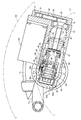
【図1】 本発明によるクサビ作動式ブレーキ装置の一実施形態を示す部分破断側面図である。
【図2】 図1に示した歯車伝達機構、ネジ送り機構、クサビ伝達機構、隙間自動調整機構等と両パッドおよびディスクロータ等との関係を示す断面図である。
【図3】 図2に示したクサビ伝達機構部分の拡大断面図である。
【図4】 図3の4−4線に沿った断面図である。
【符号の説明】
11…ディスクロータ、12…インナパッド、13…アウタパッド、14…ピストン、15…キャリパ、20…電気モータ、21…回転軸、30…歯車伝達機構、31…入力歯車、32…中間歯車、33…出力歯車、40…ネジ送り機構、41…ネジ軸(入力要素)、42…ボールナット、50…クサビ伝達機構、51…クサビ部材、51a,51b…クサビ面、52…ピストン側プレート、52a…係合平面、53…反ピストン側プレート、53a…係合斜面、54…ローラ、55…ホルダ、55a…プレート部、55b…連結柱、60…隙間自動調整機構。[0001]
BACKGROUND OF THE INVENTION
The present invention relates to a wedge-actuated brake device, and in particular, by converting a linear brake actuation input obtained by actuation of an actuator into a brake actuation output in the piston axial direction by a wedge transmission mechanism, the piston is driven in the axial direction. Thus, the present invention relates to a wedge-operated brake device configured to generate a braking force.
[0002]
[Prior art]
This type of brake device is shown, for example, in U.S. Pat. No. 4,235,312, in which a wedge transmission mechanism includes a piston-side member that moves integrally with the piston, An anti-piston side member disposed so as to be opposed to the piston side member and provided integrally with the housing, and a wedge that is disposed between these members and engages with the engagement surfaces of the members via rollers. A member and a cage for rotatably holding the roller. In this brake device, the brake operation input is configured to act as a pressing force on the wedge member.
[0003]
[Problems to be solved by the invention]
In the conventional brake device described above, there is no one that defines the positional relationship between the wedge member and the engagement surface of each member, and therefore the position of the engagement surface of each member may be out of the normal position with respect to the wedge member. In this case, the desired wedge effect cannot be obtained, and the desired brake output efficiency cannot be obtained.
[0004]
Also, the brake operation input is configured to act as a pressing force on the wedge member, and there is no one that defines the moving direction of the wedge member with respect to the engagement surface of each member. If the movement directions of the two are not in line, the load transmission member that transmits the brake operation input to the wedge member causes a large load transmission loss when the load is transmitted from the load transmission member to the wedge member. May significantly decrease, and the brake output efficiency may decrease.
[0005]
[Means for Solving the Problems]
The present invention has been made to cope with the above-described problems. By converting a linear brake operation input obtained by the operation of the actuator into a brake operation output in the piston axial direction by a wedge transmission mechanism, the cylinder unit In the wedge-operated brake device configured to generate a braking force by driving the piston assembled in the axial direction thereof, the wedge transmission mechanism includes a piston-side plate that moves integrally with the piston, An anti-piston side plate that is disposed opposite to the piston side plate and provided integrally with the housing, and a wedge member that is disposed between these plates and engages with the engagement surface of each plate via a roller. And holding the roller rotatably and holding the wedge member so as to move linearly. When moving is configured to include the said holder is movable by being guided by the plates, the holder, a pair of sandwiching the said wedge member and said piston-side plate opposite piston side plate in the axial direction of the roller The present invention is characterized in that it includes a plate portion and a plurality of connecting columns that integrally connect the pair of plate portions (the invention according to claim 1).
[0006]
In this case, it is desirable that the linear brake operation input obtained by the operation of the actuator acts as a tensile force on the wedge member (the invention according to claim 2).
[0007]
[Operation and effect of the invention]
In the wedge-operated brake device according to the present invention, the linear brake operation input obtained by the operation of the actuator is converted into the brake operation output in the piston axial direction by the wedge transmission mechanism, and the piston is moved in the axial direction by this brake operation output. To obtain a braking force.
[0008]
By the way, in this wedge-operated brake device, a wedge member, a piston side plate, a pair of plate portions that sandwich the anti-piston side plate in the axial direction of the roller, and a plurality of plates that integrally connect the pair of plate portions. The roller is rotatably held by the holder having a structure including the connecting column, and the wedge member is held so as to be linearly movable. When the wedge member is linearly moved, the holder is moved by the piston side plate and the anti-piston side plate. Move guided.
[0009]
For this reason, it is possible to prescribe | regulate the positional relationship of each member, such as a piston side plate, an anti- piston side plate , a roller, and a wedge member, and the moving direction of the wedge member with respect to a piston side plate and an anti- piston side plate with a holder. . Accordingly, the piston side plate, the anti-piston side plate , the roller and the like are held at regular positions with respect to the wedge member, and the desired wedge effect can be stably obtained, and the brake output efficiency is stabilized. It is possible.
[0010]
Further, when the linear brake operation input obtained by the operation of the actuator is configured to act as a pulling force on the wedge member when the present invention is implemented, the action direction of the brake operation input and the movement direction of the wedge member are Even when they do not coincide and are not in a straight line, the load transmission from the load transmission member that transmits the brake operation input to the wedge member to the wedge member can be stably obtained. Therefore, compared with the case where the brake operation input acts as a pressing force on the wedge member, it is possible to reduce the load transmission loss when the load is transmitted from the load transmission member to the wedge member and to increase the load transmission efficiency. Yes, it is possible to stabilize while improving the brake output efficiency.
[0011]
DETAILED DESCRIPTION OF THE INVENTION
Hereinafter, an embodiment of the present invention will be described with reference to the drawings. 1 to 4 show an embodiment in which the present invention is applied to a disc brake device for a vehicle. The disc brake device of this embodiment has wheels (in FIG. 1, the inner diameter position Wr of the tire rim is shown by a virtual line). A pair of
[0012]
The electric disc brake device includes an
[0013]
As shown in FIG. 2, the
[0014]
The
[0015]
The
[0016]
The
[0017]
The
[0018]
The
[0019]
The
[0020]
As shown in FIGS. 2 and 3, the
[0021]
On the other hand, the
[0022]
Further, the
[0023]
The automatic
[0024]
A sealing
[0025]
In this automatic
[0026]
By the way, when the adjusting
[0027]
Therefore, in the automatic
[0028]
Note that when the return movement amount of the
[0029]
In the electric disc brake device according to this embodiment configured as described above, when the rotating
[0030]
Further, the driving force converted in the screw shaft direction by the
[0031]
Therefore, the
[0032]
By the way, in the disc brake device of this embodiment, each
[0033]
For this reason, the
[0034]
In the disc brake device of this embodiment, the driving force in the screw shaft direction (linear brake operation input) obtained through the
[0035]
Therefore, compared with the case where the brake operation input acts on the
[0036]
In the disc brake device of this embodiment, the gear transmission for transmitting the rotational driving force of the
[0037]
Further, in the disc brake device of this embodiment, the rotating
[0038]
In the above embodiment, the present invention is applied to an embodiment in which a linear brake operation input acting as a pulling force on the
[0039]
In the above embodiment, the present invention is applied to the movable caliper type disc brake device. However, the present invention is applicable not only to other types of disc brake devices, but also to drum brake devices, for example. It is possible to carry out in the same manner or with appropriate modifications.
[Brief description of the drawings]
FIG. 1 is a partially cutaway side view showing an embodiment of a wedge-actuated brake device according to the present invention.
2 is a cross-sectional view showing the relationship between the gear transmission mechanism, screw feed mechanism, wedge transmission mechanism, gap automatic adjustment mechanism, etc. shown in FIG.
FIG. 3 is an enlarged cross-sectional view of a wedge transmission mechanism portion shown in FIG.
4 is a cross-sectional view taken along line 4-4 of FIG.
[Explanation of symbols]
DESCRIPTION OF
Claims (2)
前記クサビ伝達機構を、前記ピストンと一体的に移動するピストン側プレートと、このピストン側プレートに対向して配置されてハウジングに一体的に設けた反ピストン側プレートと、これら両プレート間に配置されて各プレートの係合面に対してローラを介してそれぞれ係合するクサビ部材と、前記ローラを回転可能に保持するとともに前記クサビ部材を直線移動可能に保持して前記クサビ部材の直線移動時には前記両プレートによりガイドされて移動可能なホルダとを備える構成とし、
前記ホルダを、前記クサビ部材と前記ピストン側プレートと前記反ピストン側プレートを前記ローラの軸方向にて挟持する一対のプレート部と、これら一対のプレート部を一体的に連結する複数の連結柱とを備える構成としたことを特徴とするクサビ作動式ブレーキ装置。By converting the linear brake operation input obtained by the actuator operation into the brake operation output in the piston axial direction by the wedge transmission mechanism, the piston assembled in the cylinder portion is driven in the axial direction, and the braking force is increased. In the wedge-operated brake device configured to generate,
The wedge transmission mechanism is disposed between a piston side plate that moves integrally with the piston, an anti-piston side plate that is disposed opposite to the piston side plate and is provided integrally with the housing, and the two plates. A wedge member that engages with an engagement surface of each plate via a roller, and holds the roller rotatably and holds the wedge member so that the wedge member can move linearly. It is configured to include a movable holder guided by both plates ,
The holder includes a pair of plate portions that sandwich the wedge member, the piston side plate, and the anti-piston side plate in the axial direction of the roller, and a plurality of connecting columns that integrally connect the pair of plate portions. wedge actuated brake system being characterized in that the arrangement comprises a.
Priority Applications (3)
| Application Number | Priority Date | Filing Date | Title |
|---|---|---|---|
| JP2002231518A JP4000949B2 (en) | 2002-08-08 | 2002-08-08 | Wedge-operated brake device |
| US10/627,817 US6991071B2 (en) | 2002-08-08 | 2003-07-28 | Wedge-operated brake apparatus |
| DE10336250A DE10336250B4 (en) | 2002-08-08 | 2003-08-07 | Wedge actuated brake device |
Applications Claiming Priority (1)
| Application Number | Priority Date | Filing Date | Title |
|---|---|---|---|
| JP2002231518A JP4000949B2 (en) | 2002-08-08 | 2002-08-08 | Wedge-operated brake device |
Publications (3)
| Publication Number | Publication Date |
|---|---|
| JP2004068976A JP2004068976A (en) | 2004-03-04 |
| JP2004068976A5 JP2004068976A5 (en) | 2005-09-29 |
| JP4000949B2 true JP4000949B2 (en) | 2007-10-31 |
Family
ID=31492376
Family Applications (1)
| Application Number | Title | Priority Date | Filing Date |
|---|---|---|---|
| JP2002231518A Expired - Fee Related JP4000949B2 (en) | 2002-08-08 | 2002-08-08 | Wedge-operated brake device |
Country Status (3)
| Country | Link |
|---|---|
| US (1) | US6991071B2 (en) |
| JP (1) | JP4000949B2 (en) |
| DE (1) | DE10336250B4 (en) |
Families Citing this family (7)
| Publication number | Priority date | Publication date | Assignee | Title |
|---|---|---|---|---|
| JP4000949B2 (en) | 2002-08-08 | 2007-10-31 | 株式会社アドヴィックス | Wedge-operated brake device |
| JP2004125162A (en) * | 2002-08-08 | 2004-04-22 | Advics:Kk | Wedge operation type disc brake device |
| JP2004068977A (en) * | 2002-08-08 | 2004-03-04 | Advics:Kk | Wedge actuation type disc brake device |
| JP2007064249A (en) * | 2005-08-29 | 2007-03-15 | Advics:Kk | Wedge type disc brake device |
| US20070227837A1 (en) * | 2006-03-28 | 2007-10-04 | Akebono Corporation (North America) | Wedge roller ramp parking brake assembly |
| US8636660B1 (en) | 2012-10-09 | 2014-01-28 | Regents Of The University Of Minnesota | System and method for dynamic multi-stage test administration for detection of cardiovascular disease |
| DE102015203440B4 (en) * | 2015-02-26 | 2020-12-03 | Saf-Holland Gmbh | Braking unit |
Family Cites Families (27)
| Publication number | Priority date | Publication date | Assignee | Title |
|---|---|---|---|---|
| US3237724A (en) * | 1964-01-31 | 1966-03-01 | Lambert & Brake Corp | Cam-operated, spot brake structure |
| GB1092686A (en) | 1965-03-15 | 1967-11-29 | Heinz Teves | Improvements in or relating to hydraulic brakes |
| FR2192658A5 (en) * | 1972-07-07 | 1974-02-08 | Pont A Mousson | |
| GB1458362A (en) | 1973-01-05 | 1976-12-15 | Girling Ltd | Brakes |
| US3966028A (en) * | 1975-03-07 | 1976-06-29 | Rockwell International Corporation | Automatic brake adjusting mechanism |
| US4064973A (en) * | 1976-11-18 | 1977-12-27 | The Bendix Corporation | Actuating and adjusting mechanism for disc brakes |
| US4235312A (en) * | 1978-10-30 | 1980-11-25 | Eaton Corporation | Brake actuator assembly |
| US4194596A (en) * | 1978-12-29 | 1980-03-25 | Eaton Corporation | Disc brake housing assembly |
| US4229250A (en) * | 1979-02-28 | 1980-10-21 | Valmet Oy | Method of improving properties of mechanical paper pulp without chemical reaction therewith |
| BR8005530A (en) * | 1979-08-31 | 1981-03-17 | Lucas Industries Ltd | DRUM BRAKE - INTERNAL SHOES FOR VEHICLES |
| US4301897A (en) * | 1979-12-13 | 1981-11-24 | Cox Jr Frank T | Slack adjuster |
| US4510020A (en) * | 1980-06-12 | 1985-04-09 | Pulp And Paper Research Institute Of Canada | Lumen-loaded paper pulp, its production and use |
| FR2504224B1 (en) | 1981-04-17 | 1988-06-24 | Valeo | BRAKE CONTROLLER WITH A WEAR TRACKING DEVICE |
| FR2547004B1 (en) * | 1983-05-31 | 1987-08-28 | Dba | AUTOMATICALLY ADJUSTABLE BRAKE MOTOR |
| DE3325085C2 (en) | 1983-07-12 | 1987-01-15 | Bergische Achsenfabrik Fr. Kotz & Söhne, 5276 Wiehl | Actuating device for a disc brake |
| US4623047A (en) * | 1985-11-15 | 1986-11-18 | Eaton Corporation | Automatic brake adjustment assembly |
| FR2590219B1 (en) * | 1985-11-20 | 1991-02-01 | Bendix France | ELECTRIC BRAKING DEVICE FOR VEHICLE |
| SE456826B (en) * | 1986-04-18 | 1988-11-07 | Svenska Traeforskningsinst | SET TO REDUCE ENERGY CONSUMPTION BY REFINING CELLULOSALLY MATERIAL |
| US4793447A (en) * | 1986-12-23 | 1988-12-27 | Allied-Signal Inc. | Electrically operated disc brake |
| FR2610053B1 (en) * | 1987-01-22 | 1989-03-31 | Bendix France | METHOD AND DEVICE FOR ACTUATING A BRAKING MECHANISM BY A ROTARY ELECTRIC MOTOR |
| JPH0341233A (en) * | 1989-07-06 | 1991-02-21 | Honda Motor Co Ltd | Electric brake |
| FR2667410B1 (en) * | 1990-09-28 | 1992-12-18 | Bendix Europ Services Tech | ELECTROMECHANICAL CONTROL WITH CENTRIFUGAL STRUCTURE. |
| US5223090A (en) * | 1991-03-06 | 1993-06-29 | The United States Of America As Represented By The Secretary Of Agriculture | Method for fiber loading a chemical compound |
| US5348123A (en) * | 1991-09-02 | 1994-09-20 | Akebono Brake Industry Co., Ltd. | Brake actuating apparatus for a vehicle |
| JP2004068977A (en) * | 2002-08-08 | 2004-03-04 | Advics:Kk | Wedge actuation type disc brake device |
| JP4000949B2 (en) | 2002-08-08 | 2007-10-31 | 株式会社アドヴィックス | Wedge-operated brake device |
| JP2004125163A (en) * | 2002-08-08 | 2004-04-22 | Advics:Kk | Electric braking device |
-
2002
- 2002-08-08 JP JP2002231518A patent/JP4000949B2/en not_active Expired - Fee Related
-
2003
- 2003-07-28 US US10/627,817 patent/US6991071B2/en not_active Expired - Fee Related
- 2003-08-07 DE DE10336250A patent/DE10336250B4/en not_active Expired - Fee Related
Also Published As
| Publication number | Publication date |
|---|---|
| DE10336250B4 (en) | 2006-04-27 |
| DE10336250A1 (en) | 2004-05-06 |
| US6991071B2 (en) | 2006-01-31 |
| JP2004068976A (en) | 2004-03-04 |
| US20040026185A1 (en) | 2004-02-12 |
Similar Documents
| Publication | Publication Date | Title |
|---|---|---|
| JP4711562B2 (en) | Brake device with electric brake mechanism | |
| US7635050B2 (en) | Electric brake assembly | |
| JP4496515B2 (en) | Electric brake device | |
| US6938736B2 (en) | Electric parking brake mechanism | |
| JP4399754B2 (en) | Electric disc brake | |
| US11719296B2 (en) | Brake system with torque distributing assembly | |
| WO2007089300A2 (en) | Electric actuator unit for a vehicle brake assembly | |
| JP2017502228A (en) | Actuator having irreversible screw nut system, drum brake, and brake device including the same | |
| JP4000949B2 (en) | Wedge-operated brake device | |
| JP4556153B2 (en) | Electric disc brake | |
| KR20220118318A (en) | Friction brake system for a vehicle | |
| JP2546348Y2 (en) | Brake actuator | |
| JP2001130402A (en) | Electric brake | |
| WO2005078309A1 (en) | Motor-driven brake device | |
| JP2004068977A (en) | Wedge actuation type disc brake device | |
| JP4055037B2 (en) | Electric disc brake | |
| JPH0225939Y2 (en) | ||
| JP4357385B2 (en) | Electric brake device | |
| JPH07291120A (en) | Electrically operated brake device | |
| JP2004125163A (en) | Electric braking device | |
| JP2004125162A (en) | Wedge operation type disc brake device | |
| JP4051650B2 (en) | Electric disc brake | |
| JP2000283195A (en) | Electric disc brake | |
| JP4161718B2 (en) | Disc brake device | |
| JP3793511B2 (en) | Disc brake device with parking brake mechanism |
Legal Events
| Date | Code | Title | Description |
|---|---|---|---|
| A521 | Written amendment |
Free format text: JAPANESE INTERMEDIATE CODE: A523 Effective date: 20050426 |
|
| A621 | Written request for application examination |
Free format text: JAPANESE INTERMEDIATE CODE: A621 Effective date: 20050426 |
|
| A977 | Report on retrieval |
Free format text: JAPANESE INTERMEDIATE CODE: A971007 Effective date: 20061102 |
|
| A131 | Notification of reasons for refusal |
Free format text: JAPANESE INTERMEDIATE CODE: A131 Effective date: 20061107 |
|
| A521 | Written amendment |
Free format text: JAPANESE INTERMEDIATE CODE: A523 Effective date: 20061218 |
|
| A131 | Notification of reasons for refusal |
Free format text: JAPANESE INTERMEDIATE CODE: A131 Effective date: 20070306 |
|
| TRDD | Decision of grant or rejection written | ||
| A01 | Written decision to grant a patent or to grant a registration (utility model) |
Free format text: JAPANESE INTERMEDIATE CODE: A01 Effective date: 20070724 |
|
| A61 | First payment of annual fees (during grant procedure) |
Free format text: JAPANESE INTERMEDIATE CODE: A61 Effective date: 20070806 |
|
| FPAY | Renewal fee payment (event date is renewal date of database) |
Free format text: PAYMENT UNTIL: 20100824 Year of fee payment: 3 |
|
| R150 | Certificate of patent or registration of utility model |
Free format text: JAPANESE INTERMEDIATE CODE: R150 |
|
| FPAY | Renewal fee payment (event date is renewal date of database) |
Free format text: PAYMENT UNTIL: 20110824 Year of fee payment: 4 |
|
| FPAY | Renewal fee payment (event date is renewal date of database) |
Free format text: PAYMENT UNTIL: 20110824 Year of fee payment: 4 |
|
| FPAY | Renewal fee payment (event date is renewal date of database) |
Free format text: PAYMENT UNTIL: 20120824 Year of fee payment: 5 |
|
| FPAY | Renewal fee payment (event date is renewal date of database) |
Free format text: PAYMENT UNTIL: 20120824 Year of fee payment: 5 |
|
| FPAY | Renewal fee payment (event date is renewal date of database) |
Free format text: PAYMENT UNTIL: 20130824 Year of fee payment: 6 |
|
| LAPS | Cancellation because of no payment of annual fees |