JP4482395B2 - Substrate bonding method and bonding apparatus - Google Patents
Substrate bonding method and bonding apparatus Download PDFInfo
- Publication number
- JP4482395B2 JP4482395B2 JP2004226993A JP2004226993A JP4482395B2 JP 4482395 B2 JP4482395 B2 JP 4482395B2 JP 2004226993 A JP2004226993 A JP 2004226993A JP 2004226993 A JP2004226993 A JP 2004226993A JP 4482395 B2 JP4482395 B2 JP 4482395B2
- Authority
- JP
- Japan
- Prior art keywords
- substrate
- substrates
- holding
- state
- holding table
- Prior art date
- Legal status (The legal status is an assumption and is not a legal conclusion. Google has not performed a legal analysis and makes no representation as to the accuracy of the status listed.)
- Expired - Lifetime
Links
- 239000000758 substrate Substances 0.000 title claims description 346
- 238000000034 method Methods 0.000 title claims description 15
- 239000000565 sealant Substances 0.000 claims description 37
- 238000007789 sealing Methods 0.000 claims description 30
- 239000003795 chemical substances by application Substances 0.000 claims description 29
- 230000002093 peripheral effect Effects 0.000 claims description 20
- 239000012530 fluid Substances 0.000 claims description 13
- 238000010030 laminating Methods 0.000 claims description 8
- 239000012298 atmosphere Substances 0.000 claims description 6
- 230000001276 controlling effect Effects 0.000 claims description 2
- 230000001105 regulatory effect Effects 0.000 claims description 2
- 239000004973 liquid crystal related substance Substances 0.000 description 65
- 238000003384 imaging method Methods 0.000 description 25
- 239000007789 gas Substances 0.000 description 15
- 239000000853 adhesive Substances 0.000 description 5
- 230000001070 adhesive effect Effects 0.000 description 5
- 239000011248 coating agent Substances 0.000 description 4
- 238000000576 coating method Methods 0.000 description 4
- 230000006837 decompression Effects 0.000 description 3
- 238000003825 pressing Methods 0.000 description 3
- IJGRMHOSHXDMSA-UHFFFAOYSA-N Atomic nitrogen Chemical compound N#N IJGRMHOSHXDMSA-UHFFFAOYSA-N 0.000 description 2
- 238000010586 diagram Methods 0.000 description 2
- 238000009826 distribution Methods 0.000 description 2
- 239000007788 liquid Substances 0.000 description 2
- 239000000463 material Substances 0.000 description 2
- 238000013459 approach Methods 0.000 description 1
- 238000001514 detection method Methods 0.000 description 1
- 238000006073 displacement reaction Methods 0.000 description 1
- 238000005401 electroluminescence Methods 0.000 description 1
- 238000004519 manufacturing process Methods 0.000 description 1
- 239000011159 matrix material Substances 0.000 description 1
- 229910052757 nitrogen Inorganic materials 0.000 description 1
- 230000000630 rising effect Effects 0.000 description 1
- 239000003566 sealing material Substances 0.000 description 1
- 238000003860 storage Methods 0.000 description 1
- 239000000126 substance Substances 0.000 description 1
- 239000003190 viscoelastic substance Substances 0.000 description 1
Images


Classifications
-
- G—PHYSICS
- G02—OPTICS
- G02F—OPTICAL DEVICES OR ARRANGEMENTS FOR THE CONTROL OF LIGHT BY MODIFICATION OF THE OPTICAL PROPERTIES OF THE MEDIA OF THE ELEMENTS INVOLVED THEREIN; NON-LINEAR OPTICS; FREQUENCY-CHANGING OF LIGHT; OPTICAL LOGIC ELEMENTS; OPTICAL ANALOGUE/DIGITAL CONVERTERS
- G02F1/00—Devices or arrangements for the control of the intensity, colour, phase, polarisation or direction of light arriving from an independent light source, e.g. switching, gating or modulating; Non-linear optics
- G02F1/01—Devices or arrangements for the control of the intensity, colour, phase, polarisation or direction of light arriving from an independent light source, e.g. switching, gating or modulating; Non-linear optics for the control of the intensity, phase, polarisation or colour
- G02F1/13—Devices or arrangements for the control of the intensity, colour, phase, polarisation or direction of light arriving from an independent light source, e.g. switching, gating or modulating; Non-linear optics for the control of the intensity, phase, polarisation or colour based on liquid crystals, e.g. single liquid crystal display cells
- G02F1/133—Constructional arrangements; Operation of liquid crystal cells; Circuit arrangements
- G02F1/1333—Constructional arrangements; Manufacturing methods
- G02F1/1339—Gaskets; Spacers; Sealing of cells
-
- G—PHYSICS
- G02—OPTICS
- G02F—OPTICAL DEVICES OR ARRANGEMENTS FOR THE CONTROL OF LIGHT BY MODIFICATION OF THE OPTICAL PROPERTIES OF THE MEDIA OF THE ELEMENTS INVOLVED THEREIN; NON-LINEAR OPTICS; FREQUENCY-CHANGING OF LIGHT; OPTICAL LOGIC ELEMENTS; OPTICAL ANALOGUE/DIGITAL CONVERTERS
- G02F1/00—Devices or arrangements for the control of the intensity, colour, phase, polarisation or direction of light arriving from an independent light source, e.g. switching, gating or modulating; Non-linear optics
- G02F1/01—Devices or arrangements for the control of the intensity, colour, phase, polarisation or direction of light arriving from an independent light source, e.g. switching, gating or modulating; Non-linear optics for the control of the intensity, phase, polarisation or colour
- G02F1/13—Devices or arrangements for the control of the intensity, colour, phase, polarisation or direction of light arriving from an independent light source, e.g. switching, gating or modulating; Non-linear optics for the control of the intensity, phase, polarisation or colour based on liquid crystals, e.g. single liquid crystal display cells
- G02F1/1303—Apparatus specially adapted to the manufacture of LCDs
-
- G—PHYSICS
- G02—OPTICS
- G02F—OPTICAL DEVICES OR ARRANGEMENTS FOR THE CONTROL OF LIGHT BY MODIFICATION OF THE OPTICAL PROPERTIES OF THE MEDIA OF THE ELEMENTS INVOLVED THEREIN; NON-LINEAR OPTICS; FREQUENCY-CHANGING OF LIGHT; OPTICAL LOGIC ELEMENTS; OPTICAL ANALOGUE/DIGITAL CONVERTERS
- G02F2201/00—Constructional arrangements not provided for in groups G02F1/00 - G02F7/00
- G02F2201/46—Fixing elements
- G02F2201/465—Snap -fit
-
- G—PHYSICS
- G02—OPTICS
- G02F—OPTICAL DEVICES OR ARRANGEMENTS FOR THE CONTROL OF LIGHT BY MODIFICATION OF THE OPTICAL PROPERTIES OF THE MEDIA OF THE ELEMENTS INVOLVED THEREIN; NON-LINEAR OPTICS; FREQUENCY-CHANGING OF LIGHT; OPTICAL LOGIC ELEMENTS; OPTICAL ANALOGUE/DIGITAL CONVERTERS
- G02F2202/00—Materials and properties
- G02F2202/28—Adhesive materials or arrangements
Landscapes
- Physics & Mathematics (AREA)
- Nonlinear Science (AREA)
- Chemical & Material Sciences (AREA)
- Crystallography & Structural Chemistry (AREA)
- General Physics & Mathematics (AREA)
- Optics & Photonics (AREA)
- Liquid Crystal (AREA)
- Mathematical Physics (AREA)
- Engineering & Computer Science (AREA)
- Manufacturing & Machinery (AREA)
- Devices For Indicating Variable Information By Combining Individual Elements (AREA)
- Lining Or Joining Of Plastics Or The Like (AREA)
Description
この発明は2枚の基板を、これらの基板間に流体を介在させてシール剤を介して貼り合わせる貼り合わせ方法及び貼り合わせ装置に関する。 The present invention relates to a bonding method and a bonding apparatus in which two substrates are bonded together with a fluid interposed between these substrates via a sealing agent.
液晶ディスプレイパネルに代表されるフラットディスプレイパネルなどの製造工程では、2枚の基板を所定の間隔で対向させ、これら基板間に流体としての液晶を封入してシール剤によって貼り合せる、貼り合わせ作業が行なわれる。 In the manufacturing process of a flat display panel typified by a liquid crystal display panel, two substrates are opposed to each other at a predetermined interval, and a liquid crystal as a fluid is sealed between the substrates and bonded with a sealant. Done.
上記貼り合わせ作業は、2枚の基板のどちらかに上記シール剤を枠状に塗布し、その基板或いは他方の基板の上記シール剤の枠内に対応する部分に所定量の上記液晶を複数の粒状にして滴下供給する。 In the bonding operation, the sealing agent is applied in a frame shape to one of the two substrates, and a predetermined amount of the liquid crystal is applied to a portion corresponding to the inside of the sealing agent frame of the substrate or the other substrate. It is granulated and supplied dropwise.
つぎに、上記2枚の基板を上部保持テーブルと下部保持テーブルとに保持し、上下方向に所定の間隔で離間させて対向させ、その状態でこれら基板の水平方向であるX、Y及びθ方向の位置決めを行ない、ついでこれら基板を貼り合せる。 Next, the two substrates are held on the upper holding table and the lower holding table, and are opposed to each other at a predetermined interval in the vertical direction. In this state, the horizontal directions of these substrates are the X, Y, and θ directions. Then, these substrates are bonded together.
2枚の基板の水平方向の位置合わせを行なう場合、位置合わせ精度はμm単位の高い精度が要求されるため、位置合わせ用のカメラとしては焦点深度が比較的浅い、高倍率のカメラが用いられる。 When the two substrates are aligned in the horizontal direction, the alignment accuracy is required to be as high as μm. Therefore, a high-magnification camera having a relatively shallow depth of focus is used as the alignment camera. .
高倍率のカメラを用いて2枚の基板を位置合わせする場合、これら基板が上下方向に大きな間隔、たとえば2枚の基板が比較的大きな間隔で離間した状態で位置合わせを行なったのでは、高倍率のカメラの焦点深度内に2枚の基板を同時に位置させることができない。そのため、これら基板を高精度に位置決めすることができず、位置合わせ精度が低下するということがある。 When aligning two substrates using a high-magnification camera, if the substrates are aligned with a large distance in the vertical direction, for example, with the two substrates separated by a relatively large distance, Two substrates cannot be positioned at the same time within the depth of focus of the camera with the magnification. Therefore, these substrates cannot be positioned with high accuracy, and the alignment accuracy may be lowered.
そこで、従来は2枚の基板を位置合わせする際、これらの基板を貼り合わせ状態とほぼ同じ間隔とし、その状態で2枚の基板を高倍率のカメラで撮像し、その撮像結果に基づいて一方の基板をX、Y及びθ方向に駆動して位置合わせするということが行なわれている。このような従来技術は特許文献1に示されている。
ところで、2枚の基板を貼り合わせ状態とほぼ同じ間隔にすると、二枚の基板の間で液晶が押し潰されて広がり、基板間の全体に液晶がほぼ充満した状態となる。また、このとき一方の基板は他方の基板に塗布されたシール材に接触することもある。そのため、カメラの撮像結果に基づいて一方の基板を水平方向に移動させようとしても、上記シール剤や液晶から受ける抵抗によって基板を移動させるために必要とする力が増大するため、その抵抗に抗して一方の基板を水平方向に精度よく、かつ円滑に移動させることができないということがある。 By the way, when the two substrates are set to have approximately the same distance as the bonded state, the liquid crystal is crushed and spread between the two substrates, and the entire liquid crystal is almost completely filled between the substrates. At this time, one substrate may come into contact with the sealing material applied to the other substrate. Therefore, even if one substrate is moved in the horizontal direction based on the imaging result of the camera, the force required to move the substrate due to the resistance received from the sealant or the liquid crystal is increased. As a result, one substrate may not be moved accurately and smoothly in the horizontal direction.
しかも、上記粘性抵抗が基板の保持力よりも大きくなると、基板が保持テーブル上でずれ動くということがある。そのため、基板の保持力を大きくし、粘性抵抗によってずれ動くのを防止しなければならなくなるから、基板の保持力を大きくするためのコストが増大するということもある。 In addition, if the viscous resistance is greater than the holding force of the substrate, the substrate may be displaced on the holding table. Therefore, since the holding force of the substrate must be increased to prevent the substrate from shifting due to viscous resistance, the cost for increasing the holding force of the substrate may increase.
この発明は、一方の基板を比較的軽い力で移動させて2枚の基板を精度よく、位置合わせすることができるようにした基板の位置合わせ方法及び位置が合わせ装置を提供することにある。 It is an object of the present invention to provide a substrate alignment method and alignment apparatus in which one substrate is moved with a relatively light force so that two substrates can be aligned accurately.
この発明は、二枚の基板のどちらかにシール剤が枠状に塗布され、上記二枚の基板のどちらかの上記シール剤の枠内に対応する部分に流体が滴下されていて、これら二枚の基板を上記シール剤を介して貼り合わす貼り合わせ方法であって、
下部保持テーブルの上面に一方の基板を保持し、上記下部保持テーブルに対向して設けられた上部保持テーブルの下面に他方の基板を保持する工程と、
減圧雰囲気下で上記一方の基板と上記他方の基板を、両基板が上記流体を介して接触するが上記シール剤を介しては接触しない位置まで接近させたときに発生する、当該両基板を貼り合わせるための貼り合わせ荷重より小さい接触荷重が付与された状態で相対的に水平方向に駆動して位置合わせする工程と、
上記位置合わせ工程後、この位置合わせ工程で付与される上記接触荷重を維持した状態で上方に位置する上記他方の基板の保持状態を解除する工程と、
上記他方の基板の保持状態を解除した後、上記他方の基板の保持状態を解除する工程によって上記二枚の基板の周辺部が上記シール剤を介して接触した状態で、上記減圧雰囲気の圧力を上昇させて上記二枚の基板の内外の圧力差により上記二枚の基板を上記貼り合わせ荷重により加圧して上記シール剤を介して貼り合わす工程と
を具備したことを特徴とする基板の貼り合わせ方法にある。
The present invention, sealant is applied in a frame shape on either of the two substrates, have fluid in the portion corresponding to the frame of either the sealant of the two substrates are dropped, they two A laminating method for laminating a plurality of substrates through the sealing agent,
Holding one substrate on the upper surface of the lower holding table and holding the other substrate on the lower surface of the upper holding table provided facing the lower holding table;
Affixing the two substrates, which occurs when the one substrate and the other substrate are brought close to a position where the substrates are in contact with each other through the fluid but not in contact with the sealant in a reduced pressure atmosphere. A process of relatively horizontally driving and aligning in a state where a contact load smaller than a bonding load for alignment is applied;
After the alignment step, the step of releasing the holding state of the other substrate positioned above in a state where the contact load applied in the alignment step is maintained;
After releasing the holding state of the other substrate, the step of releasing the holding state of the other substrate in a state where the periphery of the two substrates are in contact via the sealant, the pressure of the reduced pressure atmosphere It is raised bonding of the substrate, characterized by comprising the steps of: adjust stuck through the sealing agent is pressurized by a load laminated above the two substrates by pressure difference between the inside and the outside of the two substrates Is in the way.
上記二枚の基板が流体を介して接触する直前に、これら二枚の基板を位置合わせする工程をさらに備えていることが好ましい。 Just before the two substrates are in contact via the fluid, preferably further includes the step of aligning these two substrates.
上方に位置する上記他方の基板は、周辺部と中央部とが別々に保持されていて、上記他方の基板の保持状態を解除する工程は、上記他方の基板における周辺部の保持状態を解除してから中央部の保持状態を解除することが好ましい。 The other substrate is positioned upward, and the peripheral portion and the central portion is being held separately, the step of releasing the holding state of the other substrate, releases the holding state of the peripheral portion of the substrate of the other side Then, it is preferable to release the holding state of the central portion.
上記貼り合わす工程において、上記二枚の基板が設けられた雰囲気は、上記二枚の基板に加わる圧力を徐々に増加させるように圧力が上昇されることが好ましい。 In the step of match stick above, the atmosphere in which the two substrates are provided, it is preferable that the pressure is increased so as to gradually increase the pressure applied to the two substrates.
この発明は、二枚の基板のどちらかにシール剤が枠状に塗布され、上記二枚の基板のどちらかの上記シール剤の枠内に対応する部分に流体が滴下されていて、これら二枚の基板を上記シール剤を介して貼り合わす貼り合わせ装置であって、
チャンバと、
このチャンバ内の圧力を調整する圧力調整手段と、
上記チャンバ内に設けられ上面に一方の基板が載置される下部保持テーブルと、
この下部保持テーブルに対向して設けられ下面に他方の基板を保持する上部保持テーブルと、
上記下部保持テーブルと上記上部保持テーブルとを相対的に接離する方向および水平方向に駆動する駆動手段と、
上記圧力調整手段を制御して上記チャンバ内を減圧させ、その状態で上記駆動手段を制御して、上記二枚の基板が上記流体を介して接触するが上記シール剤を介しては接触しない位置まで接近させたときに発生する、当該両基板を貼り合わせるための貼り合わせ荷重より小さい接触荷重が付与された状態でこれら二枚の基板の水平方向の位置合わせをし、この位置合わせ時に付与される上記接触荷重を維持した状態で上記上部保持テーブルに保持された上記他方の基板の保持状態を解除した後、上記他方の基板の保持状態を解除したことによって上記二枚の基板の周辺部が上記シール剤を介して接触した状態で、上記圧力調整手段を制御して上記チャンバ内の圧力を上昇させることで上記貼り合わせ荷重により上記二枚の基板を上記シール剤を介して貼り合わす制御手段と
を具備したことを特徴とする基板の貼り合わせ装置にある。
The present invention, sealant is applied in a frame shape on either of the two substrates, have fluid in the portion corresponding to the frame of either the sealant of the two substrates are dropped, they two A laminating apparatus for laminating a plurality of substrates through the sealing agent,
A chamber;
Pressure adjusting means for adjusting the pressure in the chamber;
A lower holding table provided in the chamber and on which one substrate is placed on the upper surface;
An upper holding table provided opposite to the lower holding table and holding the other substrate on the lower surface;
Driving means for driving the said lower holding table and the upper holding table relatively toward or away from and horizontally,
A position in which the inside of the chamber is depressurized by controlling the pressure adjusting means, and the driving means is controlled in that state so that the two substrates are in contact through the fluid but not in contact with the sealant. The two substrates are aligned in the horizontal direction with a contact load smaller than the bonding load for bonding the two substrates, which occurs when the two substrates are brought close to each other. that after releasing the holding state of the while maintaining the contact load of the other held in the upper holding table board, the periphery of the two substrates by releasing the holding state of the other substrate is in contact through the sealant, the pressure regulating means controlled by the sealing agent of the above two substrates by the bonding load by increasing the pressure in the chamber In bonding apparatus of the substrate, characterized by comprising a through and match stick control means.
上記上部保持テーブルには上記他方の基板の周辺部を静電気力によって保持する第1の保持手段と、上記他方の基板の中央部を静電気力によって保持する第2の保持手段とが設けられていて、上記制御手段による上記上部保持テーブルに保持された上記他方の基板の保持状態の解除は、上記第1の保持手段による上記他方の基板の周辺部の保持状態を開放してから上記第2の保持手段による上記他方の基板の中央部の保持状態を開放することが好ましい。 The upper holding table is provided with a first holding means for holding the peripheral portion of the other substrate by electrostatic force, and a second holding means for holding the central portion of the other substrate by electrostatic force. The release of the holding state of the other substrate held by the upper holding table by the control means is performed after the holding state of the peripheral portion of the other substrate by the first holding means is released . It is preferable to release the holding state of the central portion of the other substrate by the holding means.
この発明によれば、一方の基板を水平方向に移動させて二枚の基板を位置合わせする際、移動させる基板に大きな抵抗が作用することがないから、これら基板の位置合わせを容易に、しかも精度よく行なうことが可能となる。 According to the present invention, when one substrate is moved in the horizontal direction and the two substrates are aligned, a large resistance does not act on the substrate to be moved. It becomes possible to carry out with high accuracy.
以下、図面を参照しながらこの発明の実施の形態を説明する。 Embodiments of the present invention will be described below with reference to the drawings.
図1乃至図5はこの発明の第1の実施の形態を示す。図1はこの発明の液晶表示パネルの組立て装置1を示す概略図である。この組立て装置1は、シール剤の塗布装置2を有する。この塗布装置2には液晶表示パネルを構成する第1、第2の基板3,4のうちの一方である、第1の基板3が供給される。
1 to 5 show a first embodiment of the present invention. FIG. 1 is a schematic view showing an
上記塗布装置2は、第1の基板3が供給載置されるテーブル及びこのテーブルの上方に配置された塗布ノズル(ともに図示せず)を有し、この塗布ノズルが上記第1の基板3に対して相対的にX、Y及びZ方向に駆動されることで、この第1の基板3の内面には粘弾性材からなるシール剤5(図4に示す)が矩形枠状に塗布される。
The
シール剤5が塗布された第1の基板3は滴下装置7に供給される。この滴下装置7は第1の基板3が載置されるテーブル及びこのテーブルの上方に配置された滴下ノズル(ともに図示せず)を有し、この滴下ノズルが上記第1の基板3に対して相対的にX、Y及びZ方向に駆動される。それによって、この第1の基板3の内面のシール剤5によって囲まれた領域内に液状物質(流体)としての液滴状の液晶6が所定の配置パターン、たとえば行列状に滴下供給される。
The
ここで、上記第1の基板3に供給される液晶の高さhは、図4(a)に示すようにシール剤5の高さHよりも高かくなるよう設定される。つまり、第1の基板3に供給される液晶6の総量が決まれば、液滴の数によって一滴あたりの液晶6の量が決まるから、その量によって液晶6の一滴あたりの高さも決定される。したがって、第1の基板3に供給される液晶6の総量に応じて液滴の数を調整することで、h>Hとなるよう設定することが可能となる。ちなみに、通常は液晶6の高さhは0.2〜0.5mm程度であり、シール剤5の高さHは30〜40μm程度である。
Here, the height h of the liquid crystal supplied to the
液晶が滴下された第1の基板3は貼り合わせ装置11に供給される。この貼り合わせ装置11には上記第1の基板3とともに上記第2の基板4が供給される。そして、上記第1の基板3と第2の基板4とが後述するごとく位置決めされて貼り合わされる。それによって、上記液晶6が一対の基板3,4間に充填された液晶パネルが組立てられる。
The
上記貼り合わせ装置11は図2に示すようにチャンバ12を有する。このチャンバ12内は減圧ポンプ10によって所定の圧力、たとえば1Pa程度に減圧されるようになっている。チャンバ12の一側にはシャッタ13によって開閉される出し入れ口14が形成され、この出し入れ口14から上記第1の基板3と第2の基板4とが出し入れされるようになっている。
The
上記チャンバ12内には第1の保持テーブル15が設けられている。この第1の保持テーブル15は第1の駆動源16によってX、Y及びθ方向に駆動されるようになっている。第1の保持テーブル15の保持面15a(上面)にはシール剤5が塗布されるとともに液晶6が滴下された上記第1の基板3が、液晶6が滴下された内面を上方に向けて供給される。保持面15aに供給された基板3は、外面(下面)がたとえば静電気力によって上記保持面15aに所定の保持力で保持される。
A first holding table 15 is provided in the
上記第1の保持テーブル15の上方には、第2の駆動源17によって第1の保持テーブル15に対して接離するZ方向に駆動される第2の保持テーブル18が配設されている。この第2の保持テーブル18の下面の保持面18aには、上記第2の基板4が外面を静電気力によって保持される。
Above the first holding table 15, a second holding table 18 that is driven in the Z direction by the
各保持テーブル15,18にはそれぞれ複数の電極15b、18bが設けられている。これら電極15b、18bに給電すると、各保持テーブル15,18の保持面15a,18aに基板3,4を保持する静電気力を発生させることができるようになっている。
Each holding table 15 and 18 is provided with a plurality of
第1の保持テーブル15と第2の保持テーブル18との保持面15a,18aに保持された第1の基板3と第2の基板4とは、四隅部がそれぞれ上記チャンバ12の下方に配設された4組の撮像手段21(2組のみ図示)によって撮像される。各撮像手段21は第1の撮像カメラ22と、この第1の撮像カメラ22よりも撮像倍率の高い第2の撮像カメラ23を有する。
The
各撮像手段21の第1、第2の撮像カメラ22,23は、X、Y及びZテーブルを有する位置決め装置24によってX、Y、及びZ方向に駆動されるようになっており、各位置決め装置24は上記チャンバ12の下方に配置された載置板25上に設置されている。
The first and
上記チャンバ12の底壁の少なくとも各位置決め装置24が対向する部位は透明窓26に形成されている。上記チャンバ12内に配置された第1の保持テーブル15の上記透明窓26に対応する部位は、第1の保持テーブル15の保持面15aに保持された第1の基板3の四隅部及びこの第1の基板3を介して上記第2の保持テーブル18の保持面18aに保持された第2の基板4の四隅部を上記第1、第2の撮像カメラ22,23によって撮像可能とする空洞部27に形成されている。
At least a portion of the bottom wall of the
上記第1の基板3と第2の基板4との上記シール剤5よりも外方の四隅部には、図示しないがそれぞれ粗位置合わせマークと精密位置合わせマークとが設けられている。各基板3,4の粗位置合わせマークを一致させすることで、第1の基板3と第2の基板4とを粗位置合わせすることができ、各基板の精密位置合わせマークを一致させることで、一対の基板3,4を精密に位置合わせすることができる。
Although not shown, coarse alignment marks and fine alignment marks are provided on the four corners of the
なお、第1、第2の基板3,4を撮像するために、第1の保持テーブル15に空洞部27を形成したが、空洞部27を形成せずに、第1の保持テーブル15全体を透光性の材料で形成してもよい。
In addition, in order to image the 1st, 2nd board |
図3に示すように、4組の第1の撮像カメラ22と第2の撮像カメラ23(図3では1組のみ図示)の撮像信号は画像処理部31に入力されて座標信号に変換処理される。画像処理部31で変換処理された座標信号は制御装置32に設けられた演算処理部33に入力される。この演算処理部33では4組の第1の撮像カメラ22或いは第2の撮像カメラ23が撮像した第1、第2の基板3,4の四隅部の各一対の粗位置合わせマーク或いは精密位置合わせマークの雑像信号から得た座標信号に基づいて、これら基板3,4のX、Y及びθ方向の相対的な位置ずれを算出する。
As shown in FIG. 3, the imaging signals of the four sets of the
上記演算処理部33によって一対の基板3,4の位置ずれが算出されると、その位置ずれが記憶部34に記憶される一方、駆動部35にも出力される。それによって、駆動部35は、第1の保持テーブル15を駆動する第1の駆動源16に駆動信号を出力し、上記第1の保持テーブル15をX方向、Y方向及びθ方向に駆動して第1の基板3と第2の基板4とを位置合わせする。
When the position shift of the pair of
第1の基板3と第2の基板4との位置合わせは、第1の撮像カメラ22からの撮像信号に基く粗位置合わせと、第2の撮像カメラ23からの撮像信号に基く精密位置合わせとによって後述するごとく行なわれる。
The alignment between the
なお、上記制御装置32の駆動部35は、上記第2の駆動源17及び上記位置決め装置24に対しても駆動信号を出力するようになっている。上記第2の駆動源17は、第2の保持テーブル18を下降方向に駆動してその保持面18aに保持された第2の基板4を、第1の保持テーブル15の保持面15aに保持された第1の基板3に、液晶6を介して接触させる。
The
そのとき、第1の基板3に加わる第2の基板4が液晶6を介して接触する荷重、つまり接触荷重は、上記第2の駆動源17に設けられた図示しない荷重検出機構によって検出されるようになっている。上記接触荷重は、第2の保持テーブル18の重量を第1の基板3に液晶6を介してどの程度加えるかによって制御することができるようになっている。
At that time, the load with which the
上記チャンバ12には流量調整弁37を介してたとえば窒素などの加圧された気体を供給する気体供給源38が接続されている。流量調整弁37の開度を調整してチャンバ12内に供給する気体の流量を調整することで、減圧ポンプ10によって減圧されたチャンバ12内の圧力の上昇曲線を所定のプロファイルに設定することができる。上記流量調整弁38は上記駆動部35によって開度が調整されるようになっている。
A
つぎに、上記構成の貼り合わせ装置11によって第1の基板3と第2の基板4とを貼り合わせる手順を図4(a)〜(e)を参照しながら説明する。
まず、図4(a)に示すように第1の保持テーブル15に第1の基板3を保持し、第2の保持テーブル18に第2の基板4を保持した後、これら基板3,4を所定の間隔で上下方向に離間対向させる。この状態で、減圧ポンプ10を作動させてチャンバ12内を所定の圧力、たとえば0.8〜1Paに減圧した後、第1の基板3と第2の基板4との四隅部を第1の撮像カメラ22で撮像し、これら基板3,4のX、Y、θ方向の粗位置合わせを行なう。
Next, a procedure for bonding the
First, as shown in FIG. 4A, the
つぎに、第2の駆動手段17を作動させて第2の保持テーブル18を緩やかな速度でZ方向下方へ駆動する。図4(b)に示すように、第2の基板4が第1の基板3に接近すると、第2の基板4の下面は第1の基板3の上面に設けられたシール剤5と液晶6のうち、シール剤5の高さHよりも高い高さhで滴下された多数の液滴状の液晶6に接触する。液滴状の各液晶6は、毛細管現象によって図4(a)に示す半球形状の状態から図4(b)に示す鼓形状に変形する。
Next, the second driving means 17 is operated to drive the second holding table 18 downward in the Z direction at a moderate speed. As shown in FIG. 4B, when the
その結果、鼓形状の液晶6は表面張力によって球形状に戻ろうとするから、その表面張力によって第1の基板3は第2の基板4に引き寄せられる。このとき、第1の保持テーブル15による第1の基板3の保持力とその基板3の自重により基板3に作用する下向きの力とが基板3を第1の保持テーブル15上に留めようとするが、液晶6の表面張力により基板3に作用する上向きの力よりも弱ければ、図4(c)に示すように第1の基板3は第1の保持テーブル15から一時的に浮き上がる。
As a result, the drum-shaped
第2の基板4をその下面が液晶6に接触した後もなお緩やかに下降させ続けると、第1の基板3は図4(d)に示すように第1の保持テーブル15の上面に接触した後、多数の液滴状の液晶6が第2の基板4を保持した第2の保持テーブル18の重量を受ける。つまり、第1の基板3に第2の基板4が液晶を介して接触することで、接触荷重が発生する。このときの接触荷重はたとえば基板3,4の単位面積あたり0.063kg/cm2 以下になるよう設定される。
If the
二枚の基板3,4を加圧してシール剤5により貼り合わせる際の貼り合わせ荷重は、通常1kg/cm2 程度であるから、上記接触荷重は貼り合わせ荷重に比べて十分に小さい値である。つまり、二枚の基板3,4を接触荷重により液晶6を介して接触させた状態では、各保持テーブル15,18を介して各基板3,4に加わる押圧力は小さい。
Bonding load when bonding by a sealing
それによって、図4(d)に示すように第1、第2の基板3,4の間隔は、これらの基板3,4間の全体にわたって液晶6が充満せず、しかも第2の基板4がシール剤5に接触しない間隔に維持される。すなわち、液滴状の各液晶6は、図4(a)に示す半球形状の状態から図4(d)に示す鼓形状に変形するものの、隣り合う液滴状の液晶6が一体化しない状態、つまり一対の基板3,4間において全体に液晶6が未だ充満しきらない状態となっている。
As a result, as shown in FIG. 4 (d), the distance between the first and
このような状態であれば、液晶6による密着力が第1の基板3と第2の基板4との対向する全面にわたって発生することがないとともに、第2の基板4がシール剤5に接触することもないから、第2の基板4が液晶6に接することによって両基板3,4間に作用する水平方向における移動抵抗の増大が防止できる。しかも、第2の基板4がシール剤5に接することによって両基板3,4間に作用する水平方向における移動抵抗の発生を防止できる。それによって、第1の基板3を第2の基板3に対して位置合わせする際に、第1の基板3を第2の基板4に対して円滑かつ精密に動かすことが可能となる。
In such a state, the adhesion force by the
第1、第2の基板3,4に接触荷重を加えた状態で、第2の撮像カメラ23によって第1の基板3と第2の基板4との四隅部に設けられた図示しない位置合わせマークを撮像する。第2の撮像カメラ23の撮像信号は画像処理部31で座標信号に変換処理されて制御装置32に入力される。それによって、制御装置32は第1の駆動源16を作動させて第1の保持テーブル15を駆動し、第1の基板3を第2の基板4に対して高精度に位置合わせする。
Alignment marks (not shown) provided at the four corners of the
位置合わせに際し、第1、第2の基板3,4に加えられる荷重は、上述したように貼り合わせ荷重に比べて十分に小さい接触荷重に維持されている。それによって、第2の基板4は、第1の基板3に塗布されたシール剤5に接触せず、しかも第1の基板3との対向面間の全体に液晶6が充満しない状態に維持される。
In positioning, the load applied to the first and
そのため、第1の基板3にシール剤5の接着力が作用したり、液晶6の密着力が第1の基板3と第2の基板4との対向する面の全体にわたって発生するということが防止できる。その結果、第1の基板3を第2の基板4に対して比較的軽い力で円滑にX、Y及びθ方向に移動させ、これら基板の位置合わせを高精度に行なうことができる。
Therefore, it is possible to prevent the adhesive force of the
すなわち、隣り合う液滴状の液晶6が一体化して一対の基板3,4間に充満すると、液晶6による密着力が基板3,4の対向面の全体に作用するため、その密着力が大きくなって第2の基板4に対し第1の基板3を水平方向に精度よく移動させることができなくなる。
That is, when adjacent
しかしながら、位置合わせ時に基板3,4に加える荷重が接触荷重であると、貼り合わせ荷重に比べて十分少ない荷重であるので、隣り合う液滴状の液晶6が一体化して基板3,4間の全体にわたって充満することが防止でき、しかも、第2の基板4がシール剤5に接触するということも防止できる。そのため、第1の基板3を比較的軽い力で円滑に移動させることが可能となるから、これら基板3,4の位置合わせ精度を向上させることが可能となる。
However, if the load applied to the
このようにして、図4(d)に示すように第1の基板3と第2の基板4との位置合わせが終了し、第2の保持テーブル18の電極18bへの通電を停止し、その保持面18に保持された第2の基板4の保持状態を解除する。それによって、第2の基板4が第2の保持テーブル18から離れるので、第2の基板4は液晶6及びシール剤5を介して第1の基板3上に重ね合わされる。
In this way, as shown in FIG. 4D, the alignment between the
すなわち、第2の基板4が第2の保持テーブル18に保持された状態では、図4(d)に示すように、第2の基板4はシール剤5から離間した状態にあるが、第2の保持テーブル18による第2の基板4の保持状態が解除されると、第2の基板4のとくに周辺部が自重によって下方に撓み、シール剤5に接触する。
That is, in the state where the
第2の基板4の保持状態を解除したならば、流量調整弁37を開いて気体供給源38からチャンバ12内に気体を供給し、このチャンバ12内の圧力を上昇させる。それによって、保持状態が解除された第2の基板4と第2の保持テーブル18の保持面18aと間に気体が入り込んで重ね合わされた第1、第2の基板3,4の内外の差圧によって第1、第2の基板3,4が加圧されるから、図4(e)に示すように液晶6が押し潰されて二枚の基板3,4間に充満するとともに、これら基板3,4がシール剤5によって接着されることになる。このとき、第2の基板4は、液晶6が押し潰された分だけ下降する。
When the holding state of the
なお、図4(d)に示す状態で、第2の保持テーブル18を上昇させてからチャンバ12内に気体を導入すれば、第2の保持テーブル18の保持面18aと第2の基板4の上面との間に隙間が形成されるから、チャンバ12に導入される気体による第1、第2の基板3,4の加圧を効率よく確実に行なうことが可能となる。
If the gas is introduced into the
上記チャンバ12内に気体を供給して二枚の基板3,4を加圧する際、流量調整弁37の開度を制御し、チャンバ12内の圧力を図5の直線X若しくは曲線Yに示すプロファイルに沿って上昇させる。つまり、チャンバ12内の圧力を急激に上昇させず、緩やかに大気圧まで上昇させる。
When the gas is supplied into the
チャンバ12内の圧力を緩やかに上昇させると、二枚の基板3,4を貼り合わせるときに、これらの基板3,4に急激な加圧による衝撃が加わるのを防止できる。そのため、基板3,4がダメージを受けたり、位置決めされた基板3,4にずれが生じるのを防止できる。
When the pressure in the
さらに、接触状態にある二枚の基板3,4を内外の圧力差で加圧して貼り合わせると、第2の保持テーブル18を下降させて加圧して貼り合わせる場合に比べて基板3,4全体を均一な圧力で加圧することができる。すなわち、第1の保持テーブル15と第2の保持テーブル18との間の平坦度のばらつきを無くすことは加工上、困難を極める。このようなばらつきを有する状態で、第2の保持テーブル18を下降させることで加圧力を付与した場合、二枚の基板3,4の全面において均一な加圧を行なうことができない。
Further, when the two
したがって、シール剤5の潰れ状態が不均一になったり、二枚の基板3,4間で液晶の分布が不均一になったりという問題が生じる。そして、一旦不均一な加圧を受けて貼り合された二枚の基板3,4は、その後に内外の圧力差による加圧を付与したとしても、上述したシール剤5の不均一な潰れ状態や液晶の不均一な分布を矯正することは困難なものとなる。
Accordingly, there arises a problem that the collapsed state of the
これに対して二枚の基板3,4を接触荷重で位置合わせした後、第2の保持テーブル18による加圧を行なうことなく二枚の基板3,4に内外の差圧力による加圧力を作用させて貼り合わせた場合には、上述した平坦度のばらつきによる影響を受けることなく均一な加圧が行なえる。それによって、シール剤5の潰れ状態が不均一になるのを防止できる。つまり、二枚の基板3,4を均一な厚さで貼り合わせることが可能となる。
On the other hand, after the two
なお、上記第1の実施の形態において、基板3,4の精密位置合わせは図4(d)に示すように第2の基板4が液晶6を介して第1の基板3に接触した状態で行なうようにしたが、図4(a)に示す状態で粗位置合わせを行なった後、第2の基板4を下降させて液晶6に接触する直前で、1回目の精密位置合わせを行ない、図4(d)の状態で2回目の精密位置合わせを行なうようにしてもよい。
In the first embodiment, the precise alignment of the
このように、精密位置合わせを2回行なうようにすれば、1回の場合に比べて位置合わせ精度を向上させることができる。しかも、1回目の位置合わせは二枚の基板3,4が非接触状態であるから、容易に行なうことができる。
As described above, if the fine alignment is performed twice, the alignment accuracy can be improved as compared with the case of the single alignment. In addition, the first alignment can be easily performed because the two
二枚の基板3,4が液晶6を介して接触した状態での2回目の精密位置合わせは、1回目の位置合わせでこれら基板3,4がかなりの精度で位置合わせされているため、第2の基板4を水平方向に移動させる距離を小さくできる。つまり、二枚の基板3,4が液晶6を介して接触した状態で水平方向に移動させる距離を小さくしたり、或いはほとんどなくすことができるから、位置合わせを容易かつ確実に行なうことができる。
なお、1回目の精密位置合わせだけを行ない、2回目の精密位置合わせを省略してもよい。
The second precise alignment in a state where the two
Note that only the first precision alignment may be performed, and the second precision alignment may be omitted.
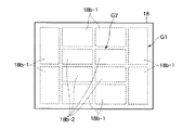
図6と図7はこの発明の第2の実施の形態を示す。この実施の形態は、図6に示すように第2の基板4を保持する第2の保持テーブル18に設けられる電極は、この第2の保持テーブル18の周辺部に位置する第1のグループG1の電極18b−1と、中央部に位置する第2のグループG2の電極18b−2とに分ける。第1のグループG1は8つの電極18b−1からなり、第2のグループG2は4つの電極18b−2からなる。
6 and 7 show a second embodiment of the present invention. In this embodiment, as shown in FIG. 6, the electrodes provided on the second holding table 18 that holds the
上記構成の第2の保持テーブル18を用いて二枚の基板を貼り合わせる場合、図7(a)〜(e)に示す手順で行なわれる。まず、減圧されたチャンバ12内で、図7(a)に示すように各保持テーブル15,18に保持されて所定の距離で離間対向した第1の基板3と第2の基板4とを粗位置合わせる。
When two substrates are bonded together using the second holding table 18 having the above-described configuration, the procedure shown in FIGS. 7A to 7E is performed. First, in the decompressed
ついで、図7(b)に示すように第2の基板4が第1の基板3に設けられた液晶6に接触する直前の位置まで第2の保持テーブル18を下降させ、その状態で第1の基板3と第2の基板4とを精密位置合わせする。
Next, as shown in FIG. 7B, the second holding table 18 is lowered to a position just before the
精密位置合わせが終了したならば、第2の保持テーブル18に設けられた電極のうち、第1のグループG1の電極18b−1への通電を停止する。それによって、第2の基板4は静電気力による周辺部の保持状態が解除される。それによって、図7(c)に示すように第2の基板4の周辺部は下方へ撓むから、第2の基板4の周辺部が第1の基板3の周辺部に塗布されたシール剤5に接触する。つまり、第2の基板4の周辺部全体がシール剤5に接触することで、第1、第2の基板3,4間の空間Sがシールされる。
When the precise alignment is completed, the energization to the
つぎに、第2の保持テーブル18の第2のグループG2の電極18b−2への通電を停止する。それによって、図7(d)に示すように第2の基板4は第2の保持テーブル18から離れて第1の基板3に供給された液晶6に接触する。
Next, the energization to the
第2の基板4の保持状態を解除したならば、チャンバ12内に気体を供給し、このチャンバ12内の圧力を大気圧になるまで徐々に上昇させる。このときのチャンバ12内の圧力は、図5の直線X又は曲線Yで示すプロファイルに沿って徐々に上昇させる。
When the holding state of the
チャンバ12内に気体を供給することで、第2の基板4が加圧されるから、二枚の基板3,4を図7(e)に示すように貼り合わせることができる。貼り合わせに際し、二枚の基板3,4の周辺部はチャンバ12内に気体が供給される前にシール剤5によって接触しているから、チャンバ12内に気体を供給して加圧するとき、二枚の基板3,4間に気体が入り込んで残留するのを確実に防止することが可能となる。
Since the
また、まず、第2の保持テーブル18に設けられた電極のうち、第1のグループG1の電極18b−1への通電を停止し、第2の基板4の周辺部の保持状態を解除して第2の基板4の周辺部をシール剤5に接触させてから第2のグループG2の電極18b−2への通電を停止するようにした。
First, among the electrodes provided on the second holding table 18, the energization to the
このため、第2の基板4の第2の保持テーブル18による保持状態が完全に解除される前に、第2の基板4を第1の基板3上にシール剤5を介して接触させることができるので、精密位置合わせ後に二枚の基板3,4間に位置ずれが生じることを極力防止することができる。
Therefore, the
なお、この実施の形態において、第2の保持テーブル18に設けられる電極を2つのグループに分け、第2の基板4の周辺部の保持状態を解除してから中央部の保持状態を解除するようにしたが、第2の基板4全体の保持状態を同時に解除してこの第2の基板4を液晶6を介して第1の基板3に接触させるようにしてもよい。
In this embodiment, the electrodes provided on the second holding table 18 are divided into two groups, and the holding state of the peripheral portion of the
すなわち、図7(b)に示す状態で二枚の基板3,4を精密位置合わせした後、第2の基板4の保持状態を解除する。それによって、第2の基板4は第2の保持テーブル18から離れて、図7(d)若しくは図4(d)に示すようにシール剤5及び液晶6を介して第1の基板3に接触することになる。
That is, after the two
また、第2の保持テーブル18に設けられた電極のうち、第2の基板4の周辺部の保持状態を解除してから中央部の保持状態を解除するようにしたが、第2の基板4の中央部の保持状態を解除して第2の基板4の中央部を撓ませて液晶6に接触させてから周辺部の保持状態を解除するようにしてもよい。
In addition, among the electrodes provided on the second holding table 18, the holding state of the peripheral portion of the
また、図7(b)に示す状態から、第2の保持テーブル18を下降させて第2の基板4を第1の基板3上に液晶6を介して接触荷重で接触させ、この状態で保持テーブル18の電極18a−1、18b−1への通電を解除するようにしてもよい。
Further, from the state shown in FIG. 7B, the second holding table 18 is lowered to bring the
これらのような例においても、二枚の基板3,4を比較的軽い力で精度よく位置合わせすることができるとともに、第1の保持テーブル15と第2の保持テーブル18との間に平坦度のばらつきを有する場合であっても、この平坦度のばらつきによる影響を受けることなく均一な加圧が行なえるので、二枚の基板3,4を均一な厚さで貼り合わせることができる。
In these examples as well, the two
この発明は上記各実施の形態に限定されず、たとえば第1の基板を下部保持テーブルに静電気力によって保持するようにしたが、下部保持テーブルの上面にゴムなどの弾性シートを貼着し、その弾性シートの摩擦力によって第1の基板を下部保持テーブル上で移動不能に保持するようにしてもよい。この弾性シートは下部保持シートとほぼ同じ大きさであってもよく、或いは複数のブロックに分割されていてもよい。 The present invention is not limited to the above embodiments. For example, the first substrate is held on the lower holding table by electrostatic force, but an elastic sheet such as rubber is attached to the upper surface of the lower holding table. The first substrate may be held immovably on the lower holding table by the frictional force of the elastic sheet. The elastic sheet may be approximately the same size as the lower holding sheet, or may be divided into a plurality of blocks.
なお、弾性シートの表面(保持面)には、第1の基板3と弾性シートとが離れ易くなるように、弾性シートは非粘着性の材質のもの、或いは表面に粘着力を低減させる加工を施したものを用いることが好ましい。
The surface of the elastic sheet (holding surface) is made of a non-adhesive material or processed to reduce the adhesive force so that the
上記第2の実施の形態では一対の基板3,4から1つの液晶表示パネルを形成する、いわゆる一面取りの場合について説明したが、一対の基板3,4から複数の液晶表示パネルを形成する多面取りの場合がある。多面取りの場合には、図8に示すように第1の基板3にシール剤5が複数の矩形枠状に塗布されるとともに、この第1の基板3の周辺部にはダミーシール剤5aが矩形枠状に塗布されることがある。
In the second embodiment, a case where one liquid crystal display panel is formed from a pair of
このような場合、図7(c)の工程においては、第2の基板4の周辺部がダミーシール剤5aに接触することになるから、多面取りの場合であっても、第1、第2の実施の形態を行なうことは有効である。
なお、この発明においては、シール剤を第2の基板または両方の基板に塗布しても差し支えなく、さらに液晶も第2の基板または両方の基板に滴下してもよい。
In such a case, in the step of FIG. 7C, the peripheral portion of the
In the present invention, the sealant may be applied to the second substrate or both substrates, and the liquid crystal may also be dropped onto the second substrate or both substrates.
上部保持テーブルを上下方向に駆動するようにしたが、下部保持テーブル15を上下方向に駆動してもよく、さらに両方の保持テーブルを上下方向に駆動するようにしてもよい。 Although the upper holding table is driven in the vertical direction, the lower holding table 15 may be driven in the vertical direction, and both the holding tables may be driven in the vertical direction.
上記実施の形態において、第1の基板と第2の基板とをシール剤によって貼り合わせる例で説明したが、シール剤とは別に第1の基板と第2の基板とを接着するために接着剤を設け、この接着剤によって二枚の基板を貼り合わせ、シール剤は少なくとも液晶をシールする機能を有するものを用いるようにしてもよい。 In the above embodiment, the example in which the first substrate and the second substrate are bonded to each other with the sealant has been described. However, in order to bond the first substrate and the second substrate separately from the sealant, an adhesive is used. And two substrates may be bonded together with this adhesive, and a sealant having a function of sealing at least liquid crystal may be used.
また、液晶表示パネルの組立て装置の例で説明したが、他のディスプレイパネル、たとえば有機エレクトロルミネセンス表示パネルの組立て装置にも適用することも可能である。 Further, although the example of the liquid crystal display panel assembling apparatus has been described, the present invention can also be applied to other display panels, such as an organic electroluminescence display panel assembling apparatus.
10…減圧ポンプ(圧力調整手段)、12…チャンバ、15…第1の保持テーブル、16…第1の駆動源、17…第2の駆動源、22…第1の撮像カメラ、23…第2の撮像カメラ、32…制御装置、37…流量調整弁(圧力調整手段)、38…気体供給源(圧力調整手段)。
DESCRIPTION OF
Claims (6)
下部保持テーブルの上面に一方の基板を保持し、上記下部保持テーブルに対向して設けられた上部保持テーブルの下面に他方の基板を保持する工程と、
減圧雰囲気下で上記一方の基板と上記他方の基板を、両基板が上記流体を介して接触するが上記シール剤を介しては接触しない位置まで接近させたときに発生する、当該両基板を貼り合わせるための貼り合わせ荷重より小さい接触荷重が付与された状態で相対的に水平方向に駆動して位置合わせする工程と、
上記位置合わせ工程後、この位置合わせ工程で付与される上記接触荷重を維持した状態で上方に位置する上記他方の基板の保持状態を解除する工程と、
上記他方の基板の保持状態を解除した後、上記他方の基板の保持状態を解除する工程によって上記二枚の基板の周辺部が上記シール剤を介して接触した状態で、上記減圧雰囲気の圧力を上昇させて上記二枚の基板の内外の圧力差により上記二枚の基板を上記貼り合わせ荷重により加圧して上記シール剤を介して貼り合わす工程と
を具備したことを特徴とする基板の貼り合わせ方法。 Sealing agent is applied in a frame shape on either of the two substrates, a portion corresponding to the frame of either the sealant of the two substrates fluid is being dropped, these two substrates A laminating method for laminating via the sealing agent,
Holding one substrate on the upper surface of the lower holding table and holding the other substrate on the lower surface of the upper holding table provided facing the lower holding table;
Affixing the two substrates, which occurs when the one substrate and the other substrate are brought close to a position where the substrates are in contact with each other through the fluid but not in contact with the sealant in a reduced pressure atmosphere. A process of relatively horizontally driving and aligning in a state where a contact load smaller than a bonding load for alignment is applied;
After the alignment step, the step of releasing the holding state of the other substrate positioned above in a state where the contact load applied in the alignment step is maintained;
After releasing the holding state of the other substrate, the step of releasing the holding state of the other substrate in a state where the periphery of the two substrates are in contact via the sealant, the pressure of the reduced pressure atmosphere It is raised bonding of the substrate, characterized by comprising the steps of: adjust stuck through the sealing agent is pressurized by a load laminated above the two substrates by pressure difference between the inside and the outside of the two substrates Method.
チャンバと、
このチャンバ内の圧力を調整する圧力調整手段と、
上記チャンバ内に設けられ上面に一方の基板が載置される下部保持テーブルと、
この下部保持テーブルに対向して設けられ下面に他方の基板を保持する上部保持テーブルと、
上記下部保持テーブルと上記上部保持テーブルとを相対的に接離する方向および水平方向に駆動する駆動手段と、
上記圧力調整手段を制御して上記チャンバ内を減圧させ、その状態で上記駆動手段を制御して、上記二枚の基板が上記流体を介して接触するが上記シール剤を介しては接触しない位置まで接近させたときに発生する、当該両基板を貼り合わせるための貼り合わせ荷重より小さい接触荷重が付与された状態でこれら二枚の基板の水平方向の位置合わせをし、この位置合わせ時に付与される上記接触荷重を維持した状態で上記上部保持テーブルに保持された上記他方の基板の保持状態を解除した後、上記他方の基板の保持状態を解除したことによって上記二枚の基板の周辺部が上記シール剤を介して接触した状態で、上記圧力調整手段を制御して上記チャンバ内の圧力を上昇させることで上記貼り合わせ荷重により上記二枚の基板を上記シール剤を介して貼り合わす制御手段と
を具備したことを特徴とする基板の貼り合わせ装置。 Sealing agent is applied in a frame shape on either of the two substrates, a portion corresponding to the frame of either the sealant of the two substrates fluid is being dropped, these two substrates A laminating apparatus for laminating via the sealing agent,
A chamber;
Pressure adjusting means for adjusting the pressure in the chamber;
A lower holding table provided in the chamber and on which one substrate is placed on the upper surface;
An upper holding table provided opposite to the lower holding table and holding the other substrate on the lower surface;
Driving means for driving the said lower holding table and the upper holding table relatively toward or away from and horizontally,
A position in which the inside of the chamber is depressurized by controlling the pressure adjusting means, and the driving means is controlled in that state so that the two substrates are in contact through the fluid but not in contact with the sealant. The two substrates are aligned in the horizontal direction with a contact load smaller than the bonding load for bonding the two substrates that occurs when the two substrates are brought close to each other. that after releasing the holding state of the while maintaining the contact load of the other held in the upper holding table board, the periphery of the two substrates by releasing the holding state of the other substrate is in contact through the sealant, the pressure regulating means controlled by the sealing agent of the above two substrates by the bonding load by increasing the pressure in the chamber Bonding apparatus of the substrate, characterized by comprising a through and match stick control means.
Priority Applications (5)
| Application Number | Priority Date | Filing Date | Title |
|---|---|---|---|
| JP2004226993A JP4482395B2 (en) | 2004-08-03 | 2004-08-03 | Substrate bonding method and bonding apparatus |
| TW094125389A TWI379129B (en) | 2004-08-03 | 2005-07-27 | Method of bonding substrates and apparatus for bonding substrates |
| KR1020050070728A KR101170942B1 (en) | 2004-08-03 | 2005-08-02 | Method of bonding substrates and apparatus for bonding substrates |
| CN2010102275284A CN101900912B (en) | 2004-08-03 | 2005-08-03 | Apparatus for bonding substrates |
| CN2005100890593A CN1737672B (en) | 2004-08-03 | 2005-08-03 | Substrate joint method and joint device |
Applications Claiming Priority (1)
| Application Number | Priority Date | Filing Date | Title |
|---|---|---|---|
| JP2004226993A JP4482395B2 (en) | 2004-08-03 | 2004-08-03 | Substrate bonding method and bonding apparatus |
Publications (3)
| Publication Number | Publication Date |
|---|---|
| JP2006047575A JP2006047575A (en) | 2006-02-16 |
| JP2006047575A5 JP2006047575A5 (en) | 2007-09-06 |
| JP4482395B2 true JP4482395B2 (en) | 2010-06-16 |
Family
ID=36026215
Family Applications (1)
| Application Number | Title | Priority Date | Filing Date |
|---|---|---|---|
| JP2004226993A Expired - Lifetime JP4482395B2 (en) | 2004-08-03 | 2004-08-03 | Substrate bonding method and bonding apparatus |
Country Status (4)
| Country | Link |
|---|---|
| JP (1) | JP4482395B2 (en) |
| KR (1) | KR101170942B1 (en) |
| CN (2) | CN101900912B (en) |
| TW (1) | TWI379129B (en) |
Families Citing this family (15)
| Publication number | Priority date | Publication date | Assignee | Title |
|---|---|---|---|---|
| US8054437B2 (en) * | 2006-03-31 | 2011-11-08 | Citizen Holdings Co., Ltd. | Large substrate, method of manufacturing liquid crystal device from the same, and liquid crystal device obtained |
| JP4786693B2 (en) | 2008-09-30 | 2011-10-05 | 三菱重工業株式会社 | Wafer bonding apparatus and wafer bonding method |
| CN102654668B (en) * | 2011-08-01 | 2014-11-19 | 北京京东方光电科技有限公司 | Vacuum box aligning equipment and box aligning system |
| KR101311369B1 (en) * | 2011-11-25 | 2013-09-25 | (주)다이솔티모 | Apparatus for sealing electrolyte injection hole and method for manufacturing dye sensitized solar cell using the same |
| JP5852244B2 (en) * | 2012-07-30 | 2016-02-03 | 芝浦メカトロニクス株式会社 | Substrate pasting apparatus and substrate pasting method |
| WO2014178390A1 (en) | 2013-04-30 | 2014-11-06 | 旭硝子株式会社 | Device for manufacturing layered body, and method for manufacturing layered body |
| JP5705937B2 (en) * | 2013-09-13 | 2015-04-22 | 信越エンジニアリング株式会社 | Bonding device manufacturing apparatus and manufacturing method |
| JP2015158603A (en) * | 2014-02-24 | 2015-09-03 | 株式会社Sat | Substrate bonding device |
| CN104267494B (en) * | 2014-09-29 | 2017-10-10 | 华南师范大学 | Accurate contraposition and the process apparatus and method fitted under a kind of electric moistening display part liquid level |
| CN104849936B (en) * | 2015-04-15 | 2018-04-10 | 华南师范大学 | A kind of method for encapsulating electric moistening display part |
| TWI582411B (en) * | 2015-09-10 | 2017-05-11 | 由田新技股份有限公司 | Panel pressing optical inspection machine |
| US11604372B2 (en) | 2018-11-15 | 2023-03-14 | HKC Corporation Limited | Method and control device for laminating display panel as well as vacuum laminator |
| CN109581707B (en) * | 2018-11-15 | 2021-02-26 | 惠科股份有限公司 | Method for laminating display panel, control device and vacuum laminating machine |
| US11231604B2 (en) * | 2019-02-20 | 2022-01-25 | Jvckenwood Corporation | Manufacturing apparatus and manufacturing method of liquid crystal device |
| CN112937058B (en) * | 2021-03-24 | 2024-05-24 | 滁州惠科光电科技有限公司 | Air suction control method and system of vacuum laminating machine and vacuum laminating machine |
Family Cites Families (11)
| Publication number | Priority date | Publication date | Assignee | Title |
|---|---|---|---|---|
| JP2002098975A (en) | 2000-09-21 | 2002-04-05 | Seiko Epson Corp | Liquid crystal device and method of manufacture |
| JP4224959B2 (en) | 2001-08-21 | 2009-02-18 | 株式会社日立プラントテクノロジー | Liquid crystal substrate assembly equipment |
| JP2003131241A (en) | 2001-10-24 | 2003-05-08 | Matsushita Electric Ind Co Ltd | Panel alignment method of liquid crystal substrate |
| JP2003233080A (en) | 2002-02-05 | 2003-08-22 | Lg Phillips Lcd Co Ltd | Lcd bonding machine and method for fabricating lcd by using the same |
| KR100720414B1 (en) * | 2002-02-27 | 2007-05-22 | 엘지.필립스 엘시디 주식회사 | Method for manufacturing liquid crystal display device |
| US6784970B2 (en) * | 2002-02-27 | 2004-08-31 | Lg.Philips Lcd Co., Ltd. | Method of fabricating LCD |
| US6833901B2 (en) * | 2002-02-27 | 2004-12-21 | Lg. Philips Lcd Co., Ltd. | Method for fabricating LCD having upper substrate coated with sealant |
| CN1325981C (en) * | 2002-03-20 | 2007-07-11 | Lg.菲利浦Lcd株式会社 | Working platform structure of binding machine and its control method |
| US7341641B2 (en) * | 2002-03-20 | 2008-03-11 | Lg.Philips Lcd Co., Ltd. | Bonding device for manufacturing liquid crystal display device |
| KR100493384B1 (en) * | 2002-11-07 | 2005-06-07 | 엘지.필립스 엘시디 주식회사 | structure for loading of substrate in substrate bonding device for manucturing a liquid crystal display device |
| CN1183955C (en) * | 2003-04-09 | 2005-01-12 | 李保刚 | Method of continuously producing eucommia extract powder, gutta percha, eucommia resin and organic fertilizer using eucommia leaf |
-
2004
- 2004-08-03 JP JP2004226993A patent/JP4482395B2/en not_active Expired - Lifetime
-
2005
- 2005-07-27 TW TW094125389A patent/TWI379129B/en active
- 2005-08-02 KR KR1020050070728A patent/KR101170942B1/en active IP Right Grant
- 2005-08-03 CN CN2010102275284A patent/CN101900912B/en active Active
- 2005-08-03 CN CN2005100890593A patent/CN1737672B/en active Active
Also Published As
| Publication number | Publication date |
|---|---|
| CN101900912B (en) | 2012-05-23 |
| CN1737672B (en) | 2010-12-08 |
| CN1737672A (en) | 2006-02-22 |
| TW200606540A (en) | 2006-02-16 |
| TWI379129B (en) | 2012-12-11 |
| JP2006047575A (en) | 2006-02-16 |
| KR101170942B1 (en) | 2012-08-03 |
| CN101900912A (en) | 2010-12-01 |
| KR20060049044A (en) | 2006-05-18 |
Similar Documents
| Publication | Publication Date | Title |
|---|---|---|
| KR101170942B1 (en) | Method of bonding substrates and apparatus for bonding substrates | |
| CN100592171C (en) | Bonding apparatus for liquid crystal display device and the system | |
| US8617343B2 (en) | Manufacturing method of flat-panel display device and bonding press apparatus therefor | |
| KR100356772B1 (en) | Bonding method and bonding device of substrates and manufacturing method of a liquid crystal display device | |
| KR100855461B1 (en) | An adhesive chuck and apparatus for assembling substrates having the same | |
| TW200401928A (en) | Method and apparatus for fabricating bonded substrate | |
| JP2006292993A (en) | Pasting device | |
| JP4449923B2 (en) | Substrate assembly method and apparatus | |
| JP5512259B2 (en) | Method for manufacturing flat display device and attaching device therefor | |
| TW201816474A (en) | Apparatus for vacuum bonding of bonded device | |
| KR100994494B1 (en) | Apparatus for assembling substrates | |
| JP2008046265A (en) | Plate member bonding device | |
| CN100456113C (en) | Bonding apparatus and system for liquid crystal display device | |
| JP4364618B2 (en) | Substrate bonding method and bonding apparatus | |
| JP2007011132A (en) | Liquid crystal display panel, method for manufacturing liquid crystal display panel, and device for sticking substrate | |
| JP4723946B2 (en) | Substrate bonding apparatus and substrate bonding method | |
| US20090133801A1 (en) | Substrate attaching apparatus | |
| JP3848942B2 (en) | Substrate assembly method and apparatus | |
| JP4751659B2 (en) | Substrate bonding device | |
| JP4066694B2 (en) | Substrate holding method and holding apparatus, and electro-optical device manufacturing method and manufacturing apparatus | |
| JP4954968B2 (en) | Adhesive chuck and substrate bonding apparatus having the same | |
| JP4585206B2 (en) | Substrate bonding method and bonding apparatus | |
| KR20080015546A (en) | Apparatus for assembling substrates | |
| KR20170106573A (en) | Apparatus and method for bonding panels | |
| JP5172639B2 (en) | Substrate bonding device |
Legal Events
| Date | Code | Title | Description |
|---|---|---|---|
| A521 | Written amendment |
Free format text: JAPANESE INTERMEDIATE CODE: A523 Effective date: 20070725 |
|
| A621 | Written request for application examination |
Free format text: JAPANESE INTERMEDIATE CODE: A621 Effective date: 20070725 |
|
| A871 | Explanation of circumstances concerning accelerated examination |
Free format text: JAPANESE INTERMEDIATE CODE: A871 Effective date: 20080207 |
|
| A975 | Report on accelerated examination |
Free format text: JAPANESE INTERMEDIATE CODE: A971005 Effective date: 20080229 |
|
| A131 | Notification of reasons for refusal |
Free format text: JAPANESE INTERMEDIATE CODE: A131 Effective date: 20080311 |
|
| A521 | Written amendment |
Free format text: JAPANESE INTERMEDIATE CODE: A523 Effective date: 20080509 |
|
| A02 | Decision of refusal |
Free format text: JAPANESE INTERMEDIATE CODE: A02 Effective date: 20080603 |
|
| A521 | Written amendment |
Free format text: JAPANESE INTERMEDIATE CODE: A523 Effective date: 20080804 |
|
| A911 | Transfer of reconsideration by examiner before appeal (zenchi) |
Free format text: JAPANESE INTERMEDIATE CODE: A911 Effective date: 20080925 |
|
| A912 | Removal of reconsideration by examiner before appeal (zenchi) |
Free format text: JAPANESE INTERMEDIATE CODE: A912 Effective date: 20081017 |
|
| A521 | Written amendment |
Free format text: JAPANESE INTERMEDIATE CODE: A523 Effective date: 20100125 |
|
| A521 | Written amendment |
Free format text: JAPANESE INTERMEDIATE CODE: A523 Effective date: 20100218 |
|
| A01 | Written decision to grant a patent or to grant a registration (utility model) |
Free format text: JAPANESE INTERMEDIATE CODE: A01 |
|
| A61 | First payment of annual fees (during grant procedure) |
Free format text: JAPANESE INTERMEDIATE CODE: A61 Effective date: 20100319 |
|
| FPAY | Renewal fee payment (event date is renewal date of database) |
Free format text: PAYMENT UNTIL: 20130326 Year of fee payment: 3 |
|
| R150 | Certificate of patent or registration of utility model |
Ref document number: 4482395 Country of ref document: JP Free format text: JAPANESE INTERMEDIATE CODE: R150 Free format text: JAPANESE INTERMEDIATE CODE: R150 |
|
| FPAY | Renewal fee payment (event date is renewal date of database) |
Free format text: PAYMENT UNTIL: 20130326 Year of fee payment: 3 |