JP4445397B2 - X-ray imaging apparatus and imaging method - Google Patents
X-ray imaging apparatus and imaging method Download PDFInfo
- Publication number
- JP4445397B2 JP4445397B2 JP2004562931A JP2004562931A JP4445397B2 JP 4445397 B2 JP4445397 B2 JP 4445397B2 JP 2004562931 A JP2004562931 A JP 2004562931A JP 2004562931 A JP2004562931 A JP 2004562931A JP 4445397 B2 JP4445397 B2 JP 4445397B2
- Authority
- JP
- Japan
- Prior art keywords
- diffraction grating
- ray
- image
- diffraction
- imaging apparatus
- Prior art date
- Legal status (The legal status is an assumption and is not a legal conclusion. Google has not performed a legal analysis and makes no representation as to the accuracy of the status listed.)
- Expired - Lifetime
Links
Images


Classifications
-
- A—HUMAN NECESSITIES
- A61—MEDICAL OR VETERINARY SCIENCE; HYGIENE
- A61B—DIAGNOSIS; SURGERY; IDENTIFICATION
- A61B6/00—Apparatus or devices for radiation diagnosis; Apparatus or devices for radiation diagnosis combined with radiation therapy equipment
- A61B6/48—Diagnostic techniques
- A61B6/484—Diagnostic techniques involving phase contrast X-ray imaging
-
- A—HUMAN NECESSITIES
- A61—MEDICAL OR VETERINARY SCIENCE; HYGIENE
- A61B—DIAGNOSIS; SURGERY; IDENTIFICATION
- A61B6/00—Apparatus or devices for radiation diagnosis; Apparatus or devices for radiation diagnosis combined with radiation therapy equipment
- A61B6/06—Diaphragms
-
- A—HUMAN NECESSITIES
- A61—MEDICAL OR VETERINARY SCIENCE; HYGIENE
- A61B—DIAGNOSIS; SURGERY; IDENTIFICATION
- A61B6/00—Apparatus or devices for radiation diagnosis; Apparatus or devices for radiation diagnosis combined with radiation therapy equipment
- A61B6/42—Arrangements for detecting radiation specially adapted for radiation diagnosis
- A61B6/4291—Arrangements for detecting radiation specially adapted for radiation diagnosis the detector being combined with a grid or grating
-
- A—HUMAN NECESSITIES
- A61—MEDICAL OR VETERINARY SCIENCE; HYGIENE
- A61B—DIAGNOSIS; SURGERY; IDENTIFICATION
- A61B6/00—Apparatus or devices for radiation diagnosis; Apparatus or devices for radiation diagnosis combined with radiation therapy equipment
- A61B6/48—Diagnostic techniques
- A61B6/483—Diagnostic techniques involving scattered radiation
-
- G—PHYSICS
- G01—MEASURING; TESTING
- G01N—INVESTIGATING OR ANALYSING MATERIALS BY DETERMINING THEIR CHEMICAL OR PHYSICAL PROPERTIES
- G01N23/00—Investigating or analysing materials by the use of wave or particle radiation, e.g. X-rays or neutrons, not covered by groups G01N3/00 – G01N17/00, G01N21/00 or G01N22/00
- G01N23/02—Investigating or analysing materials by the use of wave or particle radiation, e.g. X-rays or neutrons, not covered by groups G01N3/00 – G01N17/00, G01N21/00 or G01N22/00 by transmitting the radiation through the material
- G01N23/04—Investigating or analysing materials by the use of wave or particle radiation, e.g. X-rays or neutrons, not covered by groups G01N3/00 – G01N17/00, G01N21/00 or G01N22/00 by transmitting the radiation through the material and forming images of the material
- G01N23/041—Phase-contrast imaging, e.g. using grating interferometers
-
- G—PHYSICS
- G01—MEASURING; TESTING
- G01N—INVESTIGATING OR ANALYSING MATERIALS BY DETERMINING THEIR CHEMICAL OR PHYSICAL PROPERTIES
- G01N23/00—Investigating or analysing materials by the use of wave or particle radiation, e.g. X-rays or neutrons, not covered by groups G01N3/00 – G01N17/00, G01N21/00 or G01N22/00
- G01N23/20—Investigating or analysing materials by the use of wave or particle radiation, e.g. X-rays or neutrons, not covered by groups G01N3/00 – G01N17/00, G01N21/00 or G01N22/00 by using diffraction of the radiation by the materials, e.g. for investigating crystal structure; by using scattering of the radiation by the materials, e.g. for investigating non-crystalline materials; by using reflection of the radiation by the materials
- G01N23/20075—Investigating or analysing materials by the use of wave or particle radiation, e.g. X-rays or neutrons, not covered by groups G01N3/00 – G01N17/00, G01N21/00 or G01N22/00 by using diffraction of the radiation by the materials, e.g. for investigating crystal structure; by using scattering of the radiation by the materials, e.g. for investigating non-crystalline materials; by using reflection of the radiation by the materials by measuring interferences of X-rays, e.g. Borrmann effect
-
- G—PHYSICS
- G21—NUCLEAR PHYSICS; NUCLEAR ENGINEERING
- G21K—HANDLING OF PARTICLES OR IONISING RADIATION NOT OTHERWISE PROVIDED FOR; IRRADIATION DEVICES; GAMMA RAY OR X-RAY MICROSCOPES
- G21K1/00—Arrangements for handling particles or ionising radiation, e.g. focusing or moderating
- G21K1/06—Arrangements for handling particles or ionising radiation, e.g. focusing or moderating using diffraction, refraction or reflection, e.g. monochromators
-
- A—HUMAN NECESSITIES
- A61—MEDICAL OR VETERINARY SCIENCE; HYGIENE
- A61B—DIAGNOSIS; SURGERY; IDENTIFICATION
- A61B6/00—Apparatus or devices for radiation diagnosis; Apparatus or devices for radiation diagnosis combined with radiation therapy equipment
- A61B6/40—Arrangements for generating radiation specially adapted for radiation diagnosis
- A61B6/4064—Arrangements for generating radiation specially adapted for radiation diagnosis specially adapted for producing a particular type of beam
- A61B6/4092—Arrangements for generating radiation specially adapted for radiation diagnosis specially adapted for producing a particular type of beam for producing synchrotron radiation
-
- G—PHYSICS
- G21—NUCLEAR PHYSICS; NUCLEAR ENGINEERING
- G21K—HANDLING OF PARTICLES OR IONISING RADIATION NOT OTHERWISE PROVIDED FOR; IRRADIATION DEVICES; GAMMA RAY OR X-RAY MICROSCOPES
- G21K2207/00—Particular details of imaging devices or methods using ionizing electromagnetic radiation such as X-rays or gamma rays
- G21K2207/005—Methods and devices obtaining contrast from non-absorbing interaction of the radiation with matter, e.g. phase contrast
Landscapes
- Health & Medical Sciences (AREA)
- Life Sciences & Earth Sciences (AREA)
- Engineering & Computer Science (AREA)
- Medical Informatics (AREA)
- Physics & Mathematics (AREA)
- General Health & Medical Sciences (AREA)
- Pathology (AREA)
- High Energy & Nuclear Physics (AREA)
- Radiology & Medical Imaging (AREA)
- Nuclear Medicine, Radiotherapy & Molecular Imaging (AREA)
- Surgery (AREA)
- Heart & Thoracic Surgery (AREA)
- Molecular Biology (AREA)
- Optics & Photonics (AREA)
- Animal Behavior & Ethology (AREA)
- Biophysics (AREA)
- Public Health (AREA)
- Veterinary Medicine (AREA)
- Biomedical Technology (AREA)
- Chemical & Material Sciences (AREA)
- Analytical Chemistry (AREA)
- Biochemistry (AREA)
- General Physics & Mathematics (AREA)
- Immunology (AREA)
- General Engineering & Computer Science (AREA)
- Crystallography & Structural Chemistry (AREA)
- Spectroscopy & Molecular Physics (AREA)
- Toxicology (AREA)
- Analysing Materials By The Use Of Radiation (AREA)
- Apparatus For Radiation Diagnosis (AREA)
Description
本発明は、X線の位相を利用するX線撮像装置に関するものである。 The present invention relates to an X-ray imaging apparatus using an X-ray phase.
可視光の領域では、回折格子によりタルボ効果を生じさせ、さらにもう一枚の回折格子を併用してモアレ縞を生成させるタルボ干渉計が知られている。これによって、可視光の波面の可視化、すなわち位相を利用した画像コントラストの生成ができる。
一方、X線の領域でも位相を用いたX線撮像装置が研究開発されており、例えば特開平10−248833号公報記載の文献が知られている。しかしながら、この技術では、装置構成が複雑、あるいは、シンクロトロン放射光という巨大なX線源が必要、という不都合があった。In the visible light region, a Talbot interferometer is known in which a Talbot effect is generated by a diffraction grating and a moire fringe is generated by using another diffraction grating together. This makes it possible to visualize the wavefront of visible light, that is, to generate image contrast using the phase.
On the other hand, an X-ray imaging apparatus using a phase in the X-ray region has been researched and developed. For example, a document described in Japanese Patent Laid-Open No. 10-248833 is known. However, this technique has a disadvantage that the apparatus configuration is complicated or a huge X-ray source called synchrotron radiation is required.
本発明は、前記の事情に鑑みてなされたものである。本発明の目的は、簡便な構造により、X線の位相を利用したX線撮像が可能な装置を提供することである。
本発明のX線撮像装置は、第1および第2の回折格子と、X線画像検出器とを備え、前記第1の回折格子は、この第1の回折格子に照射されたX線によりタルボ効果を生じる構成となっており、前記第2の回折格子は、前記第1の回折格子により回折された前記X線を回折する構成となっており、前記X線画像検出器は、前記第2の回折格子により回折された前記X線を検出する構成となっているものである。
前記第2の回折格子が、前記第1の回折格子により回折されたX線を回折することにより、第1の回折格子の前面、あるいは、第1の回折格子と第2の回折格子の間に配置された被検体によるX線の位相変化に起因する画像コントラストを形成できる。X線画像検出器は、この画像コントラストを生じたX線を検出することができる。
前記第1および第2の回折格子は、透過型のものとすることができる。
前記X線撮像装置は、さらにX線源を備えてもよい。このX線源は、第1の回折格子および第2の回折格子を介してX線画像検出器にX線を照射するものである。
前記X線撮像装置は、X線源と第1の回折格子との間に被検体を配置できるようになっていてもよい。
X線源から第1の回折格子までの距離と、第1の回折格子における周期との比を、X線源から第2の回折格子までの距離と、第2の回折格子における周期との比にほぼ等しく設定することができる。
第1の回折格子は、照射されたX線に対して約80°〜100°の位相変調を与える構成となっていてもよい。
前記第1および第2の回折格子における周期を互いにほぼ等しくしてもよい。
前記X線画像検出器で検出されるX線の画像に、モアレ縞が形成されていてもよい。
前記第1または第2の回折格子を、相対的に回転可能とし、これにより、モアレ縞の間隔を調整可能としてもよい。
前記第1および第2の回折格子が、それぞれ、前記X線を回折させる回折部材を備え、前記回折部材が、少なくとも一方向に延長され、前記第1の回折格子または第2の回折格子が、これらの回折格子面に沿い、かつ、前記回折部材に交差する方向に沿って移動可能とされていてもよい。
本発明のX線撮像方法は、X線源と、第1および第2の回折格子と、X線画像検出器とを用い、さらに、以下のステップを備える。
(1)前記X線源と前記第1の回折格子との間、または、前記第1の回折格子と前記第2の回折格子との間に被検体を配置するステップ;
(2)前記X線源から前記第1の回折格子に向けてX線を照射するステップ;
(3)前記第1の回折格子により回折されてタルボ効果を生じた前記X線が前記第2の回折格子に照射されるステップ;
(4)前記第2の回折格子より、前記第1の回折格子で回折された前記X線が回折されるステップ;
(5)前記X線画像検出器が、前記第2の回折格子により回折された前記X線を検出するステップ。The present invention has been made in view of the above circumstances. An object of the present invention is to provide an apparatus capable of X-ray imaging using the phase of X-rays with a simple structure.
The X-ray imaging apparatus of the present invention includes first and second diffraction gratings and an X-ray image detector. The second diffraction grating is configured to diffract the X-ray diffracted by the first diffraction grating, and the X-ray image detector includes the second diffraction grating. The X-rays diffracted by the diffraction grating are detected.
The second diffraction grating diffracts the X-rays diffracted by the first diffraction grating, whereby the front surface of the first diffraction grating or between the first diffraction grating and the second diffraction grating. It is possible to form an image contrast caused by the X-ray phase change caused by the placed subject. The X-ray image detector can detect X-rays that cause this image contrast.
The first and second diffraction gratings may be transmissive.
The X-ray imaging apparatus may further include an X-ray source. This X-ray source irradiates the X-ray image detector with X-rays via the first diffraction grating and the second diffraction grating.
The X-ray imaging apparatus may be configured to arrange a subject between the X-ray source and the first diffraction grating.
The ratio between the distance from the X-ray source to the first diffraction grating and the period in the first diffraction grating is the ratio between the distance from the X-ray source to the second diffraction grating and the period in the second diffraction grating. Can be set approximately equal to.
The first diffraction grating may be configured to give a phase modulation of about 80 ° to 100 ° with respect to the irradiated X-rays.
The periods in the first and second diffraction gratings may be substantially equal to each other.
Moire stripes may be formed in the X-ray image detected by the X-ray image detector.
The first or second diffraction grating may be relatively rotatable so that the moire fringe spacing can be adjusted.
Each of the first and second diffraction gratings includes a diffraction member that diffracts the X-ray, the diffraction member is extended in at least one direction, and the first diffraction grating or the second diffraction grating is It may be possible to move along these diffraction grating surfaces and along a direction intersecting the diffraction member.
The X-ray imaging method of the present invention uses an X-ray source, first and second diffraction gratings, and an X-ray image detector, and further includes the following steps.
(1) disposing a subject between the X-ray source and the first diffraction grating or between the first diffraction grating and the second diffraction grating;
(2) irradiating X-rays from the X-ray source toward the first diffraction grating;
(3) A step of irradiating the second diffraction grating with the X-rays diffracted by the first diffraction grating and causing the Talbot effect;
(4) A step of diffracting the X-ray diffracted by the first diffraction grating from the second diffraction grating;
(5) The X-ray image detector detects the X-ray diffracted by the second diffraction grating.
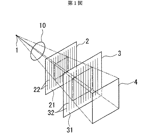
図1は、本発明の一実施形態に係るX線撮像装置の概略的な構成を示す説明図である。
図2は、第1の回折格子の断面図である。
図3は、第2の回折格子の断面図である。
図4は、図1のX線撮像装置の側面図である。
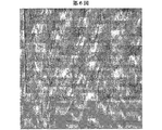
図5は、実験例1におけるX線タルボ効果の実験結果を示す図であり、回折格子から測定面までの距離が32cmの時の図である。
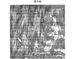
図6は、実験例1におけるX線タルボ効果の実験結果を示す図であり、回折格子から測定面までの距離が64cmの時の図である。
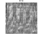
図7は、実験例1におけるX線タルボ効果の実験結果を示す図であり、回折格子から測定面までの距離が96cmの時の図である。
図8は、実験例2におけるX線タルボ干渉計の実験結果を示す図である。
図9は、実験例3において得られた位相シフト微分像を示す図である。
図10は、実験例3におけるトモグラフィで得られた立体画像である。FIG. 1 is an explanatory diagram showing a schematic configuration of an X-ray imaging apparatus according to an embodiment of the present invention.
FIG. 2 is a cross-sectional view of the first diffraction grating.
FIG. 3 is a cross-sectional view of the second diffraction grating.
FIG. 4 is a side view of the X-ray imaging apparatus of FIG.
FIG. 5 is a diagram showing experimental results of the X-ray Talbot effect in Experimental Example 1, and is a diagram when the distance from the diffraction grating to the measurement surface is 32 cm.
FIG. 6 is a diagram showing experimental results of the X-ray Talbot effect in Experimental Example 1, and is a diagram when the distance from the diffraction grating to the measurement surface is 64 cm.
FIG. 7 is a diagram showing experimental results of the X-ray Talbot effect in Experimental Example 1, and is a diagram when the distance from the diffraction grating to the measurement surface is 96 cm.
FIG. 8 is a diagram illustrating experimental results of the X-ray Talbot interferometer in Experimental Example 2.
FIG. 9 is a diagram showing a phase shift differential image obtained in Experimental Example 3.
FIG. 10 is a stereoscopic image obtained by tomography in Experimental Example 3.
本発明の一実施形態に係るX線撮像装置を以下に説明する。この撮像装置は、X線源1と、第1の回折格子2と、第2の回折格子3と、X線画像検出器4とを主要な構成として備えている(図1参照)。X線源1は、「第1の回折格子2にX線を照射したとき、タルボ効果を発生させうるだけの空間的干渉性」を有するものとする。例えば、「X線の発光点のサイズ(つまりX線源の開口径)を30ミクロン程度とし、そのX線源から約5メートル以上の位置での空間的干渉性」がそれに相当する。X線源1、回折格子2および回折格子3によってタルボ干渉計が構成される条件は後述する。
第1の回折格子2は、基板21と、この基板21に取り付けられた複数の回折部材22とを備えている(図2参照)。基板21は、例えばガラスである。複数の回折部材22は、いずれも一方向(図2中紙面の厚さ方向)に延びる線状とされている。複数の回折部材22どうしの間隔(つまり回折格子の周期)d(図2参照)は、この実施形態では、一定(つまり回折部材22どうしは等間隔)とされている。複数の回折部材22の素材としては、例えば金を用いることができる。回折部材22としては、照射されるX線に対して約80°〜100°(理想的には90°)の位相変調を与える、いわゆる位相型回折格子を構成するものであることが好ましい。つまり、回折部材22は、その部分に照射されたX線の位相速度を変化させていることになる。X線はかならずしも単色である必要はなく、上記条件を満たす範囲のエネルギー幅(つまり波長スペクトル幅)を有しても構わない。
第2の回折格子3は、前記第1の回折格子2と同様に、基板31と回折部材32とを備えている(図3参照)。第2の回折格子3は、第1の回折格子2により回折されたX線を回折することにより、画像コントラストを形成する構成となっている。第2の回折格子3については、回折部材32をより厚くした振幅型回折格子であることが望ましいが、第1の回折格子2と同様に構成することも可能である。
X線画像検出器4は、画像コントラストを生じたX線を検出するものである。このような検出器4は、従来のX線撮像装置に使われているものと同様でよいので、詳細な説明を省略する。
次に、第1・第2の回折格子2・3がタルボ干渉計を構成する条件を説明する。まず、可干渉距離1は、次のようになる。
![]()
λ:X線の波長(通常は中心波長)、
a:回折部材にほぼ直交する方向におけるX線源の開口径、
L:X線源から第1の回折格子までの距離(図4参照)、
Z1:第1の回折格子から第2の回折格子までの距離、
Z2:第2の回折格子から検出器までの距離
である。
また、第1の回折格子2と第2の回折格子3との距離Z1は、第1の回折格子2が位相型回折格子であることを前提にすれば、次の条件をほぼ満たさねばならない。
![]()
つぎに、本実施形態のX線撮像装置の動作について説明する。
この撮像装置は、X線源1と第1の回折格子2との間に被検体10(図1および図4参照)を配置した状態で使用する。ついで、X線源1から第1の回折格子2に向けてX線を照射する。すると、照射されたX線は、第1の回折格子2を通過する。このとき、第1の回折格子2では、タルボ効果を生じる。ここで、タルボ効果とは、平面波が回折格子を通過したとき、位相型回折格子の場合、式(2)で与えられる距離において回折格子の自己像を形成することである。今の場合、被検体10によるX線の位相のずれがあるので、第1の回折格子2に入射するX線の波面が歪んでいる。したがって、第1の回折格子2の自己像はそれに依存して変形している。続いて、X線は、第2の回折格子3を通過する。その結果、上記の変形した第1の回折格子2の自己像と第2の回折格子3との重ね合わせにより、X線に画像コントラストを生成することができる。画像コントラストは一般にモアレ縞となっており、X線画像検出器4により検出することができる。生成されたモアレ縞は、被検体10により変調を受けている。その変調量は、被検体10による屈折効果によってX線が曲げられた角度に比例している。したがって、X線画像検出器4で検出されたモアレ縞を解析することにより、被検体10およびその内部の構造を検出することができる。
なお、第1または第2の回折格子2・3の回折部材が、X線源とX線画像検出器を通る仮想的な軸のまわりに相対的に微小角θだけ回転して配置してあるとする。θの大きさによって、発生するモアレ縞の間隔が変わる。被検体10が無いとすると、モアレ縞の間隔はd/θで与えられる。ここでdは回折格子の周期である。微小角θを変えるための機構(例えば、第1の回折格子2および第2の回折格子3の一方を他方に対して相対的に回転させる機構)を備えれば、観察に好ましいようにモアレ縞を調整することが可能となる。また、微小角θをほぼゼロになるように調整すれば、被検体10に対応する部分以外では(つまり非変調部分では)モアレ縞は現れない。その結果、得られたX線画像では、被検体10によるコントラストのみが現れる。
また、前記の例では、被検体10がX線源1と回折格子2との間に位置する場合を説明したが、被検体10が回折格子2と回折格子3の間に位置する場合であっても、回折格子3の位置に生成される回折格子2の自己像が被検体10により変形する。したがって、この場合でも、X線画像検出器4により、前記の例と本質的に同様に、被検体10に起因して変調されたモアレ縞(画像コントラスト)を検出することができる。すなわち、本実施形態の装置では、被検体10が回折格子2と回折格子3の間に位置する場合の撮像も有効である。
本実施形態の装置によれば、X線の吸収の大小にコントラスト生成を頼る一般的方法では観察しにくい被検体に対して、簡便な構成によってX線撮像を実現することができるという利点がある。
(実験例1)
X線を回折格子に照射することによってタルボ効果を生じさせた実験例1を示す。
(実験条件)
使用X線:波長0.1nmのシンクロトロン放射光。
回折格子:厚さ150ミクロンのガラス板上に、厚さ約1ミクロンの金のパターンを周期d=8ミクロンで形成したもの。
位相型回折格子でタルボ効果が発生する条件は
![]()
本実験例1では、自己像を直接観察する目的があったために高解像度のX線画像検出器を使用したが、タルボ干渉計として使用するときはモアレ縞が観察できればよいので、必ずしも高解像度のX線画像検出器は必要としない。
(実験例2)
ここでX線タルボ効果を利用した本実施形態の実験例2を示す。
(実験条件)
使用X線:波長0.1nmのシンクロトロン放射光。
回折格子2:厚さ150ミクロンのガラス板上に、厚さ約1ミクロンの金のパターンを周期d=8ミクロンで形成したもの。
回折格子3:厚さ150ミクロンのガラス板上に、厚さ約8ミクロンの金のパターンを周期d=8ミクロンで形成したもの。
回折格子2および3の間隔Z1を、回折格子2によるタルボ効果が現れる32cmとした。被検体10として直径約1mmのプラスチック球を用いた。
被検体10は、X線源1と第1の回折格子2との間であって、かつ、第1の回折格子2の直前に配置した。
この状態で、X線源から照射されたX線を、回折格子3の直後に配置されたX線画像検出器4により検出した。その結果、図8に示される画像を得ることができた。この実験では、θ≒0°になるように調整したので、モアレ縞はほぼ発生しておらず、被検体としてのプラスチック球による位相のずれに対応するコントラストだけが現れている。この実験例では、球およびその内部に存在する気泡が明瞭に捉えられている。
なお、前記実験例2では、第1および第2の回折格子を透過型としたが、反射型でもよい。ただし、X線の反射量は一般に少ないので、透過型のほうが効率がよい。
また、前記実験例2では、第1・第2の回折格子2・3における周期を一様且つ同じとしたが、これは、図1に示す距離Z1に比べて、X線源までの距離Lが十分に大きいという仮定が可能であったからである。一般的には、X線源1から第1の回折格子2までの距離と第1の回折格子における周期との比を、X線源1から第2の回折格子3までの距離と第2の回折格子3における周期との比にほぼ等しくするのが望ましい。
さらに、前記実験例2では、第1の回折格子が、照射されたX線に対して位相差を与える構成(位相型回折格子)となっているが、X線に対して強度差を与える構成(振幅型回折格子)であってもよい。この場合、回折部材がX線を吸収する構成とすればよい。この場合でも、前記した原理でタルボ干渉計を構成できる。
また、前記実験例2では、第1および第2の回折格子2および3を平板状としているが、球面状としてもよい。この場合、線源を曲率中心とする球面とすることが好ましい。
また、前記実施形態においては、被検体または撮像系(線源と各回折格子と検出器)のいずれかを回転させて複数の投影方向で画像を取得し、それらにトモグラフィによる処理を施すことにより、被検体およびその内部の構造を立体的に観察することもできる。なお、この場合、従来のトモグラフィと異なり、屈折率分布により立体像が形成されることになり、従来のトモグラフィの感度では描出しにくい構造を描出することが可能となる。
(実験例3)
ここで、本実施形態に係る装置を用いたトモグラフィの実験例を示す。
(実験条件)
実験例3の実験条件は、実験例2と同一である。
本実施形態を用いたトモグラフィでは、つぎの三つの手順が必要となる。手順1は、X線画像検出器4により検出されたX線画像(以下「モアレ縞画像」という)から、「被検体10による屈折効果によってX線が曲げられる角度の分布像」(以下「位相シフト微分像」という)への変換である。手順2は、位相シフト微分像を積分することにより、位相のずれそのものを表す像(以下「位相シフト像」という)を取得することである。手順3は、複数の投影方向で得られる位相シフト像を用いて、トモグラフィにより立体像を再構成することである。
手順1には、縞走査法を用いる。この方法では、回折格子2あるいは3の一方を、他方に対して相対的に並進移動させる。並進方向は、移動させる回折格子の面にほぼ平行であり、かつ、回折部材にほぼ垂直な方向である。したがって、本実施形態の装置によりトモグラフィを行う場合は、第1の回折格子2または第2の回折格子3を移動させる移動機構を本実施形態の装置にさらに備えることが好ましい。
回折格子の並進移動に伴って、モアレ縞は移動し、並進距離が回折格子の1周期に達すると、モアレ縞画像は元に戻る。縞走査法は、モアレ縞画像の変化を1周期の整数分の1ずつ並進させながら記録し、それらを演算処理することにより位相シフト微分像ψ(x,y)を得るものである。(x,y)は画素の位置を示す座標である。上記並進移動量をξとして、モアレ縞画像I(x,y)は一般的に
第2の回折格子3をM=5で並進させて取得した画像から得られた位相シフト微分像ψ(x,y)を図9に示す。被検体10には、直径約1mmのプラスチック球(図8の例と同一)を用いた。図9には、プラスチック球の内部に含まれていた気泡も含めて、位相シフト微分像が良く描出されている。
位相シフト像Φ(x,y)と位相シフト微分像ψ(x,y)とは
位相シフト像Φ(x,y)は、被検体の屈折率分布をn(x,y,z)として
なお、このような撮像手法は、手順3まで進まなくては意味が無いものではなく、前記した実施形態のX線画像検出器4により直接得られた画像(生画像)、位相シフト微分像φ(x,y)、および位相シフト像Φ(x,y)のいずれも、撮像の目的に応じて十分に利用できるものである。
また、前記実施形態では、第1および第2の回折格子として基板に回折部材を取り付けた構造を示したが、この構造には限定されない。回折格子の構造としては、例えば、平板の両面に回折部材を取り付け、これにより、第1及び第2の回折部材とする構成でもよい。さらには、屈折率(または吸収率)が異なる二種類のフィルムあるいは箔を交互に多数積層し、それをフィルムあるいは箔の厚さ方向に切ることで回折格子を構成しても良い。
また、前記実施形態では、X線源1を含む構成としたが、X線源1が無い装置としてもよい。この場合は、使用時において、X線源と組み合わせればよい。
なお、前記実施形態および実施例の記載は単なる一例に過ぎず、本発明に必須の構成を示したものではない。各部の構成は、本発明の趣旨を達成できるものであれば、上記に限らない。
たとえば、前記した各実施形態における構成要素は、機能要素として存在していればよく、装置または部品としては、他の要素と統合されていてもよく、また、複数の部品によって一つの要素が実現されていてもよい。An X-ray imaging apparatus according to an embodiment of the present invention will be described below. This imaging apparatus includes an X-ray source 1, a first diffraction grating 2, a second diffraction grating 3, and an X-ray image detector 4 as main components (see FIG. 1). The X-ray source 1 is assumed to have “spatial coherence sufficient to generate the Talbot effect when the first diffraction grating 2 is irradiated with X-rays”. For example, “the spatial coherence at a position of about 5 meters or more from the X-ray source with the size of the X-ray emission point (that is, the aperture diameter of the X-ray source) of about 30 microns” corresponds to this. The conditions under which the Talbot interferometer is configured by the X-ray source 1, the diffraction grating 2, and the diffraction grating 3 will be described later.
The
Similar to the first diffraction grating 2, the
The X-ray image detector 4 detects X-rays that cause image contrast. Since such a detector 4 may be the same as that used in a conventional X-ray imaging apparatus, detailed description thereof is omitted.
Next, the conditions under which the first and
![]()
λ: X-ray wavelength (usually center wavelength),
a: Aperture diameter of the X-ray source in a direction substantially perpendicular to the diffraction member,
L: distance from the X-ray source to the first diffraction grating (see FIG. 4),
Z 1 : distance from the first diffraction grating to the second diffraction grating,
Z 2 is the distance from the second diffraction grating to the detector.
Further, the distance Z 1 between the
![]()
Next, the operation of the X-ray imaging apparatus of this embodiment will be described.
This imaging apparatus is used in a state where the subject 10 (see FIGS. 1 and 4) is disposed between the X-ray source 1 and the
The diffractive members of the first or
In the above example, the case where the subject 10 is located between the X-ray source 1 and the
According to the apparatus of this embodiment, there is an advantage that X-ray imaging can be realized with a simple configuration for a subject that is difficult to observe by a general method that relies on the generation of contrast depending on the amount of X-ray absorption. .
(Experimental example 1)
Experimental example 1 in which the Talbot effect is generated by irradiating the diffraction grating with X-rays is shown.
(Experimental conditions)
X-ray used: Synchrotron radiation with a wavelength of 0.1 nm.
Diffraction grating: A gold pattern having a thickness of about 1 micron formed on a glass plate having a thickness of 150 microns with a period d = 8 microns.
The conditions for the Talbot effect to occur in phase-type diffraction gratings are
![]()
In this Experimental Example 1, a high-resolution X-ray image detector was used because there was a purpose of directly observing a self-image. However, when using it as a Talbot interferometer, it is sufficient if moiré fringes can be observed. An X-ray image detector is not required.
(Experimental example 2)
Here, Experimental Example 2 of the present embodiment using the X-ray Talbot effect is shown.
(Experimental conditions)
X-ray used: Synchrotron radiation with a wavelength of 0.1 nm.
Diffraction grating 2: A gold pattern having a thickness of about 1 micron formed on a glass plate having a thickness of 150 microns with a period d = 8 microns.
Diffraction grating 3: A gold pattern having a thickness of about 8 microns formed on a glass plate having a thickness of 150 microns with a period d = 8 microns.
The distance Z 1 between the
The subject 10 was placed between the X-ray source 1 and the
In this state, the X-rays irradiated from the X-ray source were detected by the X-ray image detector 4 disposed immediately after the
In the experimental example 2, the first and second diffraction gratings are transmissive, but may be reflective. However, since the amount of X-ray reflection is generally small, the transmission type is more efficient.
Further, in Experimental Example 2, although a period in the first and
Furthermore, in Experimental Example 2, the first diffraction grating has a configuration that gives a phase difference to the irradiated X-ray (phase diffraction grating), but a configuration that gives an intensity difference to the X-ray. (Amplitude type diffraction grating) may be used. In this case, the diffraction member may be configured to absorb X-rays. Even in this case, the Talbot interferometer can be configured based on the principle described above.
In the experimental example 2, the first and
In the embodiment, images are acquired in a plurality of projection directions by rotating either the subject or the imaging system (a radiation source, each diffraction grating, and a detector), and processing by tomography is performed on them. Thus, the subject and the internal structure thereof can be observed three-dimensionally. In this case, unlike the conventional tomography, a three-dimensional image is formed by the refractive index distribution, and a structure that is difficult to draw with the sensitivity of the conventional tomography can be drawn.
(Experimental example 3)
Here, an experimental example of tomography using the apparatus according to the present embodiment is shown.
(Experimental conditions)
The experimental conditions of Experimental Example 3 are the same as Experimental Example 2.
In tomography using this embodiment, the following three procedures are required. The procedure 1 is based on an X-ray image detected by the X-ray image detector 4 (hereinafter referred to as “moire fringe image”) and a “distribution image of angles at which X-rays are bent by the refraction effect of the subject 10” (hereinafter “phase It is called “shift differential image”.
The procedure 1 uses a fringe scanning method. In this method, one of the
With the translational movement of the diffraction grating, the moire fringe moves, and when the translational distance reaches one period of the diffraction grating, the moire fringe image is restored. In the fringe scanning method, a change in a moire fringe image is recorded while being translated by an integer of one cycle, and a phase shift differential image ψ (x, y) is obtained by performing arithmetic processing on these. (X, y) is a coordinate indicating the position of the pixel. The moiré fringe image I (x, y) is generally represented by the above translational movement amount ξ.
FIG. 9 shows a phase shift differential image ψ (x, y) obtained from an image obtained by translating the
What is the phase shift image Φ (x, y) and the phase shift differential image ψ (x, y)?
The phase shift image Φ (x, y) has a refractive index distribution of the subject as n (x, y, z).
Note that such an imaging technique is not meaningless unless it proceeds to step 3, and an image (raw image) directly obtained by the X-ray image detector 4 of the above-described embodiment, a phase shift differential image φ. Both (x, y) and the phase shift image Φ (x, y) can be sufficiently used depending on the purpose of imaging.
In the above-described embodiment, the structure in which the diffraction member is attached to the substrate as the first and second diffraction gratings is shown. However, the present invention is not limited to this structure. As a structure of the diffraction grating, for example, a configuration in which a diffractive member is attached to both surfaces of a flat plate to thereby form the first and second diffractive members may be employed. Furthermore, a diffraction grating may be formed by alternately laminating two types of films or foils having different refractive indexes (or absorption rates) and cutting them in the thickness direction of the film or foil.
Moreover, in the said embodiment, although it was set as the structure containing the X-ray source 1, it is good also as an apparatus without the X-ray source 1. FIG. In this case, it may be combined with an X-ray source at the time of use.
Note that the description of the embodiment and the examples is merely an example, and does not indicate a configuration essential to the present invention. The configuration of each part is not limited to the above as long as the gist of the present invention can be achieved.
For example, the constituent elements in the above-described embodiments may be present as functional elements, and may be integrated with other elements as devices or parts, and one element is realized by a plurality of parts. May be.
本発明によれば、簡便な構造でX線の位相を利用したX線撮像が可能な装置を提供することができる。 ADVANTAGE OF THE INVENTION According to this invention, the apparatus which can perform the X-ray imaging using the phase of X-ray with a simple structure can be provided.
Claims (15)
前記第1および第2の回折格子は、それぞれ、前記X線を回折させる回折部材を備えており、前記回折部材は、少なくとも一方向に延長されており、前記第1の回折格子または第2の回折格子は、これらの回折格子面に沿い、かつ、前記回折部材の延長方向に交差する方向に沿って移動可能とされており、
さらに、位相シフト微分像の取得手段を備えており、
この取得手段は、前記X線画像検出器により取得されたX線画像を用いて、位相シフト微分像を取得するものであり、
この取得手段においては、前記第1回折格子及び前記第2回折格子のうちの一方に対する他方の相対移動に対応して、前記X線画像が記録されるようになっている
ことを特徴とするX線撮像装置。The first diffraction grating includes first and second diffraction gratings and an X-ray image detector. The first diffraction grating is configured to generate a Talbot effect by the X-rays irradiated to the first diffraction grating. The second diffraction grating is configured to diffract the X-ray diffracted by the first diffraction grating, and the X-ray image detector is configured to diffract the X-ray diffracted by the second diffraction grating. It is configured to detect lines ,
Each of the first and second diffraction gratings includes a diffraction member that diffracts the X-ray, and the diffraction member extends in at least one direction, and the first diffraction grating or the second diffraction grating The diffraction grating is movable along these diffraction grating surfaces and along a direction intersecting the extension direction of the diffraction member,
Furthermore, it has a phase shift differential image acquisition means,
This acquisition means acquires a phase shift differential image using the X-ray image acquired by the X-ray image detector,
In this acquisition means, the X-ray image is recorded corresponding to the relative movement of the other one of the first diffraction grating and the second diffraction grating. A featured X-ray imaging apparatus.
(1)前記X線源と前記第1の回折格子との間、または、前記第1の回折格子と前記第2の回折格子との間に被検体を配置するステップ、ここで、前記第1および第2の回折格子は、それぞれ、前記X線を回折させる回折部材を備えており、前記回折部材は、少なくとも一方向に延長されており、前記第1の回折格子または第2の回折格子は、これらの回折格子面に沿い、かつ、前記回折部材の延長方向に交差する方向に沿って移動可能とされており;
(2)前記X線源から前記第1の回折格子に向けてX線を照射するステップ;
(3)前記第1の回折格子により回折されてタルボ効果を生じた前記X線が前記第2の回折格子に照射されるステップ;
(4)前記第2の回折格子より、前記第1の回折格子で回折された前記X線が回折されるステップ;
(5)前記X線画像検出器が、前記第2の回折格子により回折された前記X線を検出するステップ。
(6)前記X線画像検出器により取得されたX線画像を用いて、位相シフト微分像を取得するステップ、ただし、ここにおいては、前記X線画像は、前記第1回折格子及び前記第2回折格子のうちの一方に対する他方の相対移動に対応して記録される。 An X-ray imaging method using an X-ray source, first and second diffraction gratings, and an X-ray image detector, and further comprising the following steps;
(1) A step of disposing an object between the X-ray source and the first diffraction grating or between the first diffraction grating and the second diffraction grating, wherein the first And the second diffraction grating each include a diffraction member that diffracts the X-ray, and the diffraction member extends in at least one direction. The first diffraction grating or the second diffraction grating is , Being movable along the diffraction grating planes and along a direction intersecting the extending direction of the diffraction member ;
(2) irradiating X-rays from the X-ray source toward the first diffraction grating;
(3) A step of irradiating the second diffraction grating with the X-rays diffracted by the first diffraction grating and causing the Talbot effect;
(4) A step of diffracting the X-ray diffracted by the first diffraction grating from the second diffraction grating;
(5) The X-ray image detector detects the X-ray diffracted by the second diffraction grating.
(6) A step of acquiring a phase shift differential image using the X-ray image acquired by the X-ray image detector, wherein the X-ray image includes the first diffraction grating and the second diffraction grating. Recorded corresponding to the relative movement of one of the diffraction gratings to the other.
Applications Claiming Priority (3)
| Application Number | Priority Date | Filing Date | Title |
|---|---|---|---|
| JP2002376018 | 2002-12-26 | ||
| JP2002376018 | 2002-12-26 | ||
| PCT/JP2003/016670 WO2004058070A1 (en) | 2002-12-26 | 2003-12-25 | X-ray imaging system and imaging method |
Publications (2)
| Publication Number | Publication Date |
|---|---|
| JPWO2004058070A1 JPWO2004058070A1 (en) | 2006-04-27 |
| JP4445397B2 true JP4445397B2 (en) | 2010-04-07 |
Family
ID=32677354
Family Applications (1)
| Application Number | Title | Priority Date | Filing Date |
|---|---|---|---|
| JP2004562931A Expired - Lifetime JP4445397B2 (en) | 2002-12-26 | 2003-12-25 | X-ray imaging apparatus and imaging method |
Country Status (5)
| Country | Link |
|---|---|
| US (1) | US7180979B2 (en) |
| EP (1) | EP1623671A4 (en) |
| JP (1) | JP4445397B2 (en) |
| AU (1) | AU2003292785A1 (en) |
| WO (1) | WO2004058070A1 (en) |
Cited By (12)
| Publication number | Priority date | Publication date | Assignee | Title |
|---|---|---|---|---|
| JP2009150875A (en) * | 2007-11-15 | 2009-07-09 | Csem Centre Suisse D'electronique & De Microtechnique Sa | Interferometer device and method |
| JP2012143497A (en) * | 2011-01-14 | 2012-08-02 | Fujifilm Corp | Radiation imaging system and control method thereof |
| WO2014092206A1 (en) | 2012-12-13 | 2014-06-19 | Canon Kabushiki Kaisha | Object information obtaining apparatus, program, and imaging system |
| US8824629B2 (en) | 2010-08-19 | 2014-09-02 | Fujifilm Corporation | Radiation imaging system and image processing method |
| WO2015122542A1 (en) | 2014-02-14 | 2015-08-20 | Canon Kabushiki Kaisha | X-ray talbot interferometer and x-ray talbot interferometer system |
| US9123451B2 (en) | 2011-01-25 | 2015-09-01 | Canon Kabushiki Kaisha | Imaging apparatus and imaging method |
| EP3530189A1 (en) | 2018-02-23 | 2019-08-28 | Konica Minolta, Inc. | X-ray imaging system |
| WO2020004175A1 (en) * | 2018-06-27 | 2020-01-02 | 株式会社ニコン | X-ray device, x-ray image generation method, and production method for structure |
| WO2020045365A1 (en) * | 2018-08-30 | 2020-03-05 | 株式会社ニコン | X-ray apparatus, method for adjusting x-ray apparatus, and method of manufacturing structure |
| US10732133B2 (en) | 2017-12-04 | 2020-08-04 | Konica Minolta, Inc. | X-ray imaging system containing X-ray apparatus having gratings and object housing for setting environmental condition independent of external environment |
| US10852255B2 (en) | 2017-12-04 | 2020-12-01 | Konica Minolta, Inc. | X-ray imaging system |
| US11221303B2 (en) | 2016-03-30 | 2022-01-11 | Konica Minolta, Inc. | Radiation capturing system |
Families Citing this family (143)
| Publication number | Priority date | Publication date | Assignee | Title |
|---|---|---|---|---|
| JP4676244B2 (en) * | 2005-05-13 | 2011-04-27 | 株式会社日立製作所 | X-ray imaging device |
| JPWO2006129462A1 (en) * | 2005-06-01 | 2008-12-25 | コニカミノルタエムジー株式会社 | Digital radiographic imaging system |
| EP1731099A1 (en) * | 2005-06-06 | 2006-12-13 | Paul Scherrer Institut | Interferometer for quantitative phase contrast imaging and tomography with an incoherent polychromatic x-ray source |
| JP4862824B2 (en) * | 2005-07-08 | 2012-01-25 | コニカミノルタエムジー株式会社 | Digital radiographic imaging system |
| WO2007074029A1 (en) * | 2005-12-27 | 2007-07-05 | Siemens Aktiengesellschaft | Focus detector arrangement for generating phase-contrast x-ray images and method for this |
| EP1803398B1 (en) | 2005-12-27 | 2010-07-14 | Siemens Aktiengesellschaft | Source-detector arrangement for X-ray phase contrast imaging and method therefor |
| DE102006017291B4 (en) * | 2006-02-01 | 2017-05-24 | Paul Scherer Institut | Focus / detector system of an X-ray apparatus for producing phase contrast recordings, X-ray system with such a focus / detector system and associated storage medium and method |
| DE102006063048B3 (en) * | 2006-02-01 | 2018-03-29 | Siemens Healthcare Gmbh | Focus / detector system of an X-ray apparatus for producing phase-contrast images |
| DE102006037255A1 (en) * | 2006-02-01 | 2007-08-02 | Siemens Ag | Focus-detector system on X-ray equipment for generating projective or tomographic X-ray phase-contrast exposures of an object under examination uses an anode with areas arranged in strips |
| DE102006017290B4 (en) * | 2006-02-01 | 2017-06-22 | Siemens Healthcare Gmbh | Focus / detector system of an X-ray apparatus, X-ray system and method for producing phase-contrast images |
| DE102006015356B4 (en) * | 2006-02-01 | 2016-09-22 | Siemens Healthcare Gmbh | Method for producing projective and tomographic phase-contrast images with an X-ray system |
| DE102006046034A1 (en) * | 2006-02-01 | 2007-08-16 | Siemens Ag | X-ray CT system for producing projective and tomographic phase-contrast images |
| DE102006037282B4 (en) * | 2006-02-01 | 2017-08-17 | Siemens Healthcare Gmbh | Focus-detector arrangement with X-ray optical grating for phase contrast measurement |
| DE102006037281A1 (en) * | 2006-02-01 | 2007-08-09 | Siemens Ag | X-ray radiographic grating of a focus-detector arrangement of an X-ray apparatus for generating projective or tomographic phase-contrast images of an examination subject |
| DE102006037256B4 (en) * | 2006-02-01 | 2017-03-30 | Paul Scherer Institut | Focus-detector arrangement of an X-ray apparatus for producing projective or tomographic phase contrast recordings and X-ray system, X-ray C-arm system and X-ray CT system |
| DE102006037254B4 (en) * | 2006-02-01 | 2017-08-03 | Paul Scherer Institut | Focus-detector arrangement for producing projective or tomographic phase-contrast images with X-ray optical grids, as well as X-ray system, X-ray C-arm system and X-ray computer tomography system |
| DE102006015358B4 (en) * | 2006-02-01 | 2019-08-22 | Paul Scherer Institut | Focus / detector system of an X-ray apparatus for producing phase-contrast images, associated X-ray system and storage medium and method for producing tomographic images |
| US7643605B2 (en) * | 2006-02-27 | 2010-01-05 | University Of Rochester | Method and apparatus for cone beam CT dynamic imaging |
| JP4702455B2 (en) * | 2007-02-07 | 2011-06-15 | コニカミノルタエムジー株式会社 | X-ray imaging device and method, and X-ray imaging apparatus |
| JP2008197593A (en) * | 2007-02-16 | 2008-08-28 | Konica Minolta Medical & Graphic Inc | Transmission type diffraction grating for x-ray, x-ray talbot interferometer and x-ray imaging apparatus |
| JP5056842B2 (en) * | 2007-02-21 | 2012-10-24 | コニカミノルタエムジー株式会社 | Radiation image capturing apparatus and radiation image capturing system |
| WO2008102574A1 (en) * | 2007-02-21 | 2008-08-28 | Konica Minolta Medical & Graphic, Inc. | X-ray photography system |
| US8411816B2 (en) | 2007-02-21 | 2013-04-02 | Konica Minolta Medical & Graphic, Inc. | Radiological image capturing apparatus and radiological image capturing system |
| WO2008102654A1 (en) * | 2007-02-21 | 2008-08-28 | Konica Minolta Medical & Graphic, Inc. | X-ray image system and x-ray image program |
| US8027039B2 (en) * | 2007-04-16 | 2011-09-27 | University Of Maryland, Baltimore | Subwavelength resolution optical microscopy |
| DE102007029730B4 (en) * | 2007-06-27 | 2017-06-08 | Paul Scherer Institut | Measuring system with a phase-contrast contrast agent and its use for the non-invasive determination of properties of an examination subject |
| EP2073040A2 (en) | 2007-10-31 | 2009-06-24 | FUJIFILM Corporation | Radiation image detector and phase contrast radiation imaging apparatus |
| US8023767B1 (en) | 2008-03-10 | 2011-09-20 | University Of Rochester | Method and apparatus for 3D metal and high-density artifact correction for cone-beam and fan-beam CT imaging |
| US8565371B2 (en) | 2008-03-19 | 2013-10-22 | Koninklijke Philips N.V. | Rotational X ray device for phase contrast imaging |
| US8809758B2 (en) * | 2008-07-25 | 2014-08-19 | Cornell University | Light field image sensor with an angle-sensitive pixel (ASP) device |
| KR101629044B1 (en) * | 2008-07-25 | 2016-06-09 | 코넬 유니버시티 | Light field image sensor, method and applications |
| JP2010063646A (en) * | 2008-09-11 | 2010-03-25 | Fujifilm Corp | Radiation phase image radiographing apparatus |
| JP2010075620A (en) * | 2008-09-29 | 2010-04-08 | Fujifilm Corp | Radiation tomosynthesis photographing apparatus |
| EP2168488B1 (en) | 2008-09-30 | 2013-02-13 | Siemens Aktiengesellschaft | X-ray CT system for x-ray phase contrast and/or x-ray dark field imaging |
| CN101726503B (en) * | 2008-10-17 | 2012-08-29 | 清华大学 | X ray phase contrast tomography |
| US8559594B2 (en) | 2008-10-29 | 2013-10-15 | Canon Kabushiki Kaisha | Imaging apparatus and imaging method |
| EP2343537B1 (en) | 2008-10-29 | 2019-04-10 | Canon Kabushiki Kaisha | X-ray imaging device and x-ray imaging method |
| WO2010092513A1 (en) * | 2009-02-12 | 2010-08-19 | Philips Intellectual Property & Standards Gmbh | Interface device, imaging system and method for rim-imaging |
| US7949095B2 (en) * | 2009-03-02 | 2011-05-24 | University Of Rochester | Methods and apparatus for differential phase-contrast fan beam CT, cone-beam CT and hybrid cone-beam CT |
| WO2010109390A1 (en) * | 2009-03-27 | 2010-09-30 | Koninklijke Philips Electronics N. V. | Achromatic phase-contrast imaging |
| JP2010236986A (en) * | 2009-03-31 | 2010-10-21 | Fujifilm Corp | Radiation phase imaging device |
| JP2010253194A (en) * | 2009-04-28 | 2010-11-11 | Fujifilm Corp | Radiation phase imaging device |
| JP5586899B2 (en) * | 2009-08-26 | 2014-09-10 | キヤノン株式会社 | X-ray phase grating and manufacturing method thereof |
| WO2011033798A1 (en) | 2009-09-16 | 2011-03-24 | コニカミノルタエムジー株式会社 | X-ray imaging device, x-ray image system, and x-ray image generation method |
| JP5759474B2 (en) * | 2009-12-10 | 2015-08-05 | コーニンクレッカ フィリップス エヌ ヴェ | Phase contrast imaging apparatus and method having movable x-ray detector elements |
| JP5631013B2 (en) | 2010-01-28 | 2014-11-26 | キヤノン株式会社 | X-ray imaging device |
| JP5213923B2 (en) * | 2010-01-29 | 2013-06-19 | キヤノン株式会社 | X-ray imaging apparatus and X-ray imaging method |
| WO2011114845A1 (en) | 2010-03-18 | 2011-09-22 | コニカミノルタエムジー株式会社 | X-ray imaging system |
| JP5438649B2 (en) | 2010-03-26 | 2014-03-12 | 富士フイルム株式会社 | Radiation imaging system and displacement determination method |
| JP5635169B2 (en) * | 2010-03-26 | 2014-12-03 | 富士フイルム株式会社 | Radiography system |
| JP2011224330A (en) * | 2010-03-29 | 2011-11-10 | Fujifilm Corp | Radiation imaging system and offset correction method therefor |
| JP2012090944A (en) | 2010-03-30 | 2012-05-17 | Fujifilm Corp | Radiographic system and radiographic method |
| JP5548085B2 (en) | 2010-03-30 | 2014-07-16 | 富士フイルム株式会社 | Adjustment method of diffraction grating |
| JP2012090945A (en) * | 2010-03-30 | 2012-05-17 | Fujifilm Corp | Radiation detection device, radiographic apparatus, and radiographic system |
| JP5796976B2 (en) | 2010-05-27 | 2015-10-21 | キヤノン株式会社 | X-ray imaging device |
| JP2012013530A (en) * | 2010-06-30 | 2012-01-19 | Fujifilm Corp | Diffraction grating, method for manufacturing the same, and radiographic device |
| JP2012022239A (en) * | 2010-07-16 | 2012-02-02 | Fujifilm Corp | Diffraction grating, manufacturing method thereof, and radiographic apparatus |
| CN103189739B (en) * | 2010-10-19 | 2015-12-02 | 皇家飞利浦电子股份有限公司 | Differential phase contrast's imaging |
| RU2572644C2 (en) * | 2010-10-19 | 2016-01-20 | Конинклейке Филипс Электроникс Н.В. | Differential phase-contrast imaging |
| JP5875280B2 (en) * | 2010-10-20 | 2016-03-02 | キヤノン株式会社 | Imaging device using Talbot interference and method for adjusting imaging device |
| JP2012093429A (en) * | 2010-10-25 | 2012-05-17 | Fujifilm Corp | Grid for radiation imaging, method of manufacturing the same, and radiation imaging system |
| JP2014014379A (en) * | 2010-10-27 | 2014-01-30 | Fujifilm Corp | Radiographic system and radiographic method |
| EP2633277B1 (en) | 2010-10-27 | 2020-06-17 | Cornell University | Angle-sensitive pixel device |
| WO2012057023A1 (en) * | 2010-10-28 | 2012-05-03 | 富士フイルム株式会社 | Radiographic imaging system and control method for same |
| JP2014014380A (en) * | 2010-10-28 | 2014-01-30 | Fujifilm Corp | Radiographic apparatus and radiographic system |
| BR112013011028A2 (en) * | 2010-11-08 | 2016-09-13 | Koninkl Philips Electronics Nv | laminated crosslinking, detector arrangement of an x-ray system. x-ray imaging system and method of producing a laminate crosslinking |
| JP5150711B2 (en) * | 2010-12-07 | 2013-02-27 | 富士フイルム株式会社 | Radiography apparatus and radiation imaging system |
| JP5150713B2 (en) * | 2010-12-08 | 2013-02-27 | 富士フイルム株式会社 | Radiation image detection device, radiation imaging device, radiation imaging system |
| EP2652708B1 (en) * | 2010-12-13 | 2015-01-28 | Paul Scherrer Institut | A method and a system for image integration using constrained optimization for phase contrast imaging with an arrangement of gratings |
| JP2012143550A (en) * | 2010-12-20 | 2012-08-02 | Fujifilm Corp | Radiation image capturing apparatus and radiation image obtaining method |
| JP5204880B2 (en) * | 2010-12-22 | 2013-06-05 | 富士フイルム株式会社 | Radiation imaging grid, manufacturing method thereof, and radiation imaging system |
| JP2012187288A (en) * | 2011-03-11 | 2012-10-04 | Canon Inc | X-ray imaging apparatus |
| JP2012200567A (en) * | 2011-03-28 | 2012-10-22 | Fujifilm Corp | Radiographic system and radiographic method |
| JP5714968B2 (en) | 2011-04-15 | 2015-05-07 | 株式会社日立ハイテクサイエンス | Diffraction grating for X-ray Talbot interferometer, manufacturing method thereof, and X-ray Talbot interferometer |
| JP2012225966A (en) | 2011-04-15 | 2012-11-15 | Seiko Instruments Inc | Diffraction grating for x-ray talbot interferometer, method for manufacturing the same, and x-ray talbot interferometer |
| JP5348172B2 (en) * | 2011-04-28 | 2013-11-20 | 株式会社島津製作所 | Radiography equipment |
| US9557280B2 (en) * | 2011-06-01 | 2017-01-31 | Total Sa | X-ray tomography device |
| WO2012164091A1 (en) | 2011-06-01 | 2012-12-06 | Total Sa | An x-ray tomography device |
| JP2013050441A (en) | 2011-08-03 | 2013-03-14 | Canon Inc | Wavefront measuring apparatus, wavefront measuring method, program and x-ray imaging apparatus |
| JP2014217398A (en) * | 2011-08-22 | 2014-11-20 | 富士フイルム株式会社 | Radiographic apparatus and method of radiography |
| JP2014217397A (en) * | 2011-08-22 | 2014-11-20 | 富士フイルム株式会社 | Radiographic apparatus and unwrapping method |
| JP2014238265A (en) * | 2011-09-30 | 2014-12-18 | 富士フイルム株式会社 | Radiation image detector and manufacturing method of the same, and radiation photographing system using radiation image detector |
| JP5475737B2 (en) | 2011-10-04 | 2014-04-16 | 富士フイルム株式会社 | Radiation imaging apparatus and image processing method |
| JP2013090920A (en) * | 2011-10-06 | 2013-05-16 | Fujifilm Corp | Radiography apparatus and image processing method |
| US20150117599A1 (en) * | 2013-10-31 | 2015-04-30 | Sigray, Inc. | X-ray interferometric imaging system |
| JP5857800B2 (en) | 2012-03-01 | 2016-02-10 | コニカミノルタ株式会社 | Joint imaging apparatus and imaging object fixing unit |
| JP6197790B2 (en) | 2012-06-11 | 2017-09-20 | コニカミノルタ株式会社 | Medical image system and medical image processing apparatus |
| US9717470B2 (en) * | 2012-08-20 | 2017-08-01 | Koninklijke Philips N.V. | Aligning source-grating-to-phase-grating distance for multiple order phase tuning in differential phase contrast imaging |
| KR101378757B1 (en) * | 2012-08-30 | 2014-03-27 | 한국원자력연구원 | Radiation imaging equipment and method available to obtain element date of material and select dimensions of image |
| JP2014135989A (en) * | 2013-01-16 | 2014-07-28 | Konica Minolta Inc | Medical image system |
| US9364191B2 (en) | 2013-02-11 | 2016-06-14 | University Of Rochester | Method and apparatus of spectral differential phase-contrast cone-beam CT and hybrid cone-beam CT |
| JP2014171799A (en) | 2013-03-12 | 2014-09-22 | Canon Inc | X-ray imaging apparatus, and x-ray imaging system |
| US9855018B2 (en) | 2013-04-08 | 2018-01-02 | Konica Minolta, Inc. | Diagnostic medical image system and method of introducing Talbot capturing device to diagnostic medical image system used for general capturing |
| EP2827339A1 (en) | 2013-07-16 | 2015-01-21 | Canon Kabushiki Kaisha | Source grating, interferometer, and object information acquisition system |
| US10416099B2 (en) | 2013-09-19 | 2019-09-17 | Sigray, Inc. | Method of performing X-ray spectroscopy and X-ray absorption spectrometer system |
| US10295485B2 (en) | 2013-12-05 | 2019-05-21 | Sigray, Inc. | X-ray transmission spectrometer system |
| US10269528B2 (en) | 2013-09-19 | 2019-04-23 | Sigray, Inc. | Diverging X-ray sources using linear accumulation |
| US10297359B2 (en) | 2013-09-19 | 2019-05-21 | Sigray, Inc. | X-ray illumination system with multiple target microstructures |
| USRE48612E1 (en) | 2013-10-31 | 2021-06-29 | Sigray, Inc. | X-ray interferometric imaging system |
| US9726622B2 (en) | 2013-10-31 | 2017-08-08 | Tohoku University | Non-destructive inspection device |
| US10304580B2 (en) | 2013-10-31 | 2019-05-28 | Sigray, Inc. | Talbot X-ray microscope |
| US10401309B2 (en) | 2014-05-15 | 2019-09-03 | Sigray, Inc. | X-ray techniques using structured illumination |
| US9626587B2 (en) * | 2014-08-28 | 2017-04-18 | Toshiba Medical Systems Corporation | Iterative reconstruction scheme for phase contrast tomography |
| JP6543838B2 (en) * | 2014-08-28 | 2019-07-17 | 株式会社緑野リサーチ | Phase imaging apparatus and restoration method thereof |
| CN106033133B (en) * | 2015-03-11 | 2019-09-17 | 同方威视技术股份有限公司 | A kind of grating, manufacturing method and radiation imaging apparatus |
| US10352880B2 (en) | 2015-04-29 | 2019-07-16 | Sigray, Inc. | Method and apparatus for x-ray microscopy |
| US10295486B2 (en) | 2015-08-18 | 2019-05-21 | Sigray, Inc. | Detector for X-rays with high spatial and high spectral resolution |
| JP6422123B2 (en) | 2015-08-27 | 2018-11-14 | 国立大学法人東北大学 | Radiation image generator |
| DE102016204046B4 (en) * | 2016-03-11 | 2018-05-24 | Siemens Healthcare Gmbh | Method and X-ray device for interferometric X-ray 2D imaging |
| JP6619268B2 (en) | 2016-03-17 | 2019-12-11 | 国立大学法人東北大学 | Radiation image generator |
| JP6741080B2 (en) * | 2016-11-22 | 2020-08-19 | 株式会社島津製作所 | X-ray phase imaging system |
| US10247683B2 (en) | 2016-12-03 | 2019-04-02 | Sigray, Inc. | Material measurement techniques using multiple X-ray micro-beams |
| JP2018128579A (en) * | 2017-02-08 | 2018-08-16 | 株式会社島津製作所 | Method of manufacturing diffraction grating |
| WO2018168621A1 (en) | 2017-03-17 | 2018-09-20 | 国立大学法人東北大学 | Radiographic image generating device |
| JP6844461B2 (en) * | 2017-07-20 | 2021-03-17 | 株式会社島津製作所 | X-ray phase imaging device and information acquisition method |
| US11013482B2 (en) * | 2017-10-31 | 2021-05-25 | Shimadzu Corporation | Phase contrast X-ray imaging system |
| JP7033779B2 (en) | 2017-11-30 | 2022-03-11 | 国立大学法人東北大学 | Radiation image generator |
| US10578566B2 (en) | 2018-04-03 | 2020-03-03 | Sigray, Inc. | X-ray emission spectrometer system |
| US10845491B2 (en) | 2018-06-04 | 2020-11-24 | Sigray, Inc. | Energy-resolving x-ray detection system |
| JP7347827B2 (en) | 2018-06-12 | 2023-09-20 | 国立大学法人 筑波大学 | Phase image capturing method and phase image capturing device using the same |
| GB2591630B (en) | 2018-07-26 | 2023-05-24 | Sigray Inc | High brightness x-ray reflection source |
| US10656105B2 (en) | 2018-08-06 | 2020-05-19 | Sigray, Inc. | Talbot-lau x-ray source and interferometric system |
| WO2020051061A1 (en) | 2018-09-04 | 2020-03-12 | Sigray, Inc. | System and method for x-ray fluorescence with filtering |
| WO2020051221A2 (en) | 2018-09-07 | 2020-03-12 | Sigray, Inc. | System and method for depth-selectable x-ray analysis |
| JP7281829B2 (en) | 2019-02-15 | 2023-05-26 | 国立大学法人東北大学 | radiographic image generator |
| JP7200816B2 (en) * | 2019-04-22 | 2023-01-10 | 株式会社島津製作所 | X-RAY PHASE IMAGING DEVICE AND X-RAY PHASE CONTRAST IMAGE GENERATING METHOD |
| DE112020004169T5 (en) | 2019-09-03 | 2022-05-25 | Sigray, Inc. | SYSTEM AND METHODS FOR COMPUTER-ASSISTED LAMINOGRAM X-RAY FLUORESCENCE IMAGING |
| US11175243B1 (en) | 2020-02-06 | 2021-11-16 | Sigray, Inc. | X-ray dark-field in-line inspection for semiconductor samples |
| JP7395775B2 (en) | 2020-05-18 | 2023-12-11 | シグレイ、インコーポレイテッド | Systems and methods for X-ray absorption spectroscopy using a crystal analyzer and multiple detector elements |
| WO2022061347A1 (en) | 2020-09-17 | 2022-03-24 | Sigray, Inc. | System and method using x-rays for depth-resolving metrology and analysis |
| US12480892B2 (en) | 2020-12-07 | 2025-11-25 | Sigray, Inc. | High throughput 3D x-ray imaging system using a transmission x-ray source |
| KR20260030946A (en) | 2020-12-07 | 2026-03-06 | 시그레이, 아이엔씨. | High throughput 3d x-ray imaging system using a transmission x-ray source |
| US11813102B2 (en) * | 2021-10-06 | 2023-11-14 | Houxun Miao | Interferometer for x-ray phase contrast imaging |
| JP7454541B2 (en) | 2021-11-24 | 2024-03-22 | 株式会社リガク | Structural information acquisition method and structural information acquisition device |
| WO2023168204A1 (en) | 2022-03-02 | 2023-09-07 | Sigray, Inc. | X-ray fluorescence system and x-ray source with electrically insulative target material |
| WO2023177981A1 (en) | 2022-03-15 | 2023-09-21 | Sigray, Inc. | System and method for compact laminography utilizing microfocus transmission x-ray source and variable magnification x-ray detector |
| CN119173759A (en) | 2022-05-02 | 2024-12-20 | 斯格瑞公司 | X-ray sequential array wavelength dispersive spectrometer |
| CN121013975A (en) | 2023-02-16 | 2025-11-25 | 斯格瑞公司 | X-ray detector system with at least two stacked planar Bragg diffractometers |
| US12181423B1 (en) | 2023-09-07 | 2024-12-31 | Sigray, Inc. | Secondary image removal using high resolution x-ray transmission sources |
| US12429437B2 (en) | 2023-11-07 | 2025-09-30 | Sigray, Inc. | System and method for x-ray absorption spectroscopy using spectral information from two orthogonal planes |
| US12429436B2 (en) | 2024-01-08 | 2025-09-30 | Sigray, Inc. | X-ray analysis system with focused x-ray beam and non-x-ray microscope |
| WO2025155719A1 (en) | 2024-01-18 | 2025-07-24 | Sigray, Inc. | Sequential array of x-ray imaging detectors |
| WO2025174966A1 (en) | 2024-02-15 | 2025-08-21 | Sigray, Inc. | System and method for generating a focused x‑ray beam |
Family Cites Families (2)
| Publication number | Priority date | Publication date | Assignee | Title |
|---|---|---|---|---|
| JP3548664B2 (en) | 1996-03-29 | 2004-07-28 | 株式会社日立製作所 | Phase contrast X-ray imaging device |
| US5812629A (en) | 1997-04-30 | 1998-09-22 | Clauser; John F. | Ultrahigh resolution interferometric x-ray imaging |
-
2003
- 2003-12-25 EP EP03768205A patent/EP1623671A4/en not_active Withdrawn
- 2003-12-25 WO PCT/JP2003/016670 patent/WO2004058070A1/en not_active Ceased
- 2003-12-25 JP JP2004562931A patent/JP4445397B2/en not_active Expired - Lifetime
- 2003-12-25 AU AU2003292785A patent/AU2003292785A1/en not_active Abandoned
-
2005
- 2005-06-22 US US11/159,568 patent/US7180979B2/en not_active Expired - Lifetime
Cited By (17)
| Publication number | Priority date | Publication date | Assignee | Title |
|---|---|---|---|---|
| JP2009150875A (en) * | 2007-11-15 | 2009-07-09 | Csem Centre Suisse D'electronique & De Microtechnique Sa | Interferometer device and method |
| US8824629B2 (en) | 2010-08-19 | 2014-09-02 | Fujifilm Corporation | Radiation imaging system and image processing method |
| JP2012143497A (en) * | 2011-01-14 | 2012-08-02 | Fujifilm Corp | Radiation imaging system and control method thereof |
| US9123451B2 (en) | 2011-01-25 | 2015-09-01 | Canon Kabushiki Kaisha | Imaging apparatus and imaging method |
| US9702831B2 (en) * | 2012-12-13 | 2017-07-11 | Canon Kabushiki Kaisha | Object information obtaining apparatus, program, and imaging system |
| WO2014092206A1 (en) | 2012-12-13 | 2014-06-19 | Canon Kabushiki Kaisha | Object information obtaining apparatus, program, and imaging system |
| US20150308967A1 (en) * | 2012-12-13 | 2015-10-29 | Canon Kabushiki Kaisha | Object information obtaining apparatus, program, and imaging system |
| US10393681B2 (en) | 2014-02-14 | 2019-08-27 | Canon Kabushiki Kaisha | X-ray Talbot interferometer and X-ray Talbot interferometer system |
| WO2015122542A1 (en) | 2014-02-14 | 2015-08-20 | Canon Kabushiki Kaisha | X-ray talbot interferometer and x-ray talbot interferometer system |
| US11221303B2 (en) | 2016-03-30 | 2022-01-11 | Konica Minolta, Inc. | Radiation capturing system |
| US10732133B2 (en) | 2017-12-04 | 2020-08-04 | Konica Minolta, Inc. | X-ray imaging system containing X-ray apparatus having gratings and object housing for setting environmental condition independent of external environment |
| US10852255B2 (en) | 2017-12-04 | 2020-12-01 | Konica Minolta, Inc. | X-ray imaging system |
| US11530994B2 (en) | 2017-12-04 | 2022-12-20 | Konica Minolta, Inc. | X-ray imaging system containing x-ray apparatus having gratings and object housing for setting environmental condition independent of external environment |
| EP3530189A1 (en) | 2018-02-23 | 2019-08-28 | Konica Minolta, Inc. | X-ray imaging system |
| US10695019B2 (en) | 2018-02-23 | 2020-06-30 | Konica Minolta, Inc. | X-ray imaging system |
| WO2020004175A1 (en) * | 2018-06-27 | 2020-01-02 | 株式会社ニコン | X-ray device, x-ray image generation method, and production method for structure |
| WO2020045365A1 (en) * | 2018-08-30 | 2020-03-05 | 株式会社ニコン | X-ray apparatus, method for adjusting x-ray apparatus, and method of manufacturing structure |
Also Published As
| Publication number | Publication date |
|---|---|
| WO2004058070A1 (en) | 2004-07-15 |
| EP1623671A1 (en) | 2006-02-08 |
| AU2003292785A1 (en) | 2004-07-22 |
| US7180979B2 (en) | 2007-02-20 |
| EP1623671A4 (en) | 2008-11-05 |
| US20050286680A1 (en) | 2005-12-29 |
| JPWO2004058070A1 (en) | 2006-04-27 |
Similar Documents
| Publication | Publication Date | Title |
|---|---|---|
| JP4445397B2 (en) | X-ray imaging apparatus and imaging method | |
| JP5777360B2 (en) | X-ray imaging device | |
| JP5631013B2 (en) | X-ray imaging device | |
| JP5601909B2 (en) | X-ray imaging apparatus and X-ray imaging method using the same | |
| US8859977B2 (en) | Wavefront measuring apparatus, wavefront measuring method, and computer-readable medium storing program | |
| JP5162453B2 (en) | Interferometer for quantitative phase contrast imaging and tomography using an incoherent polychromatic X-ray source | |
| CN201191275Y (en) | An X-ray Grating Phase Contrast Imaging System | |
| US9063055B2 (en) | X-ray imaging apparatus | |
| JP5595473B2 (en) | Subject information acquisition apparatus, X-ray imaging apparatus, subject information acquisition method, and program | |
| US20170023472A1 (en) | Apparatus and method for quantitive phase tomography through linear scanning with coherent and non-coherent detection | |
| CN101576515A (en) | System and method for X-ray optical grating contrast imaging | |
| WO2007125833A1 (en) | X-ray image picking-up device and x-ray image picking-up method | |
| US9123451B2 (en) | Imaging apparatus and imaging method | |
| JP2014178130A (en) | X-ray imaging device and x-ray imaging system | |
| US20140286475A1 (en) | Interferometer and object information acquisition system | |
| JP6537293B2 (en) | X-ray Talbot interferometer and X-ray Talbot interferometer system | |
| CN104837409A (en) | Differential phase contrast imaging device with movable grating(s) | |
| JP2013042983A (en) | Tomosynthesis imaging device and imaging method of tomosynthesis image | |
| JP2012112914A (en) | X-ray imaging apparatus and x-ray imaging method | |
| US9412481B1 (en) | Method and device for producing and using localized periodic intensity-modulated patterns with x-radiation and other wavelengths | |
| JP6604772B2 (en) | X-ray Talbot interferometer | |
| JP6566839B2 (en) | X-ray Talbot interferometer and Talbot interferometer system | |
| JPWO2018168621A1 (en) | Radiation image generator | |
| JP2012235919A (en) | X-ray imaging apparatus | |
| JP2015227784A (en) | Interferometer |
Legal Events
| Date | Code | Title | Description |
|---|---|---|---|
| A621 | Written request for application examination |
Free format text: JAPANESE INTERMEDIATE CODE: A621 Effective date: 20061019 |
|
| A521 | Request for written amendment filed |
Free format text: JAPANESE INTERMEDIATE CODE: A523 Effective date: 20071213 |
|
| A131 | Notification of reasons for refusal |
Free format text: JAPANESE INTERMEDIATE CODE: A131 Effective date: 20091020 |
|
| A521 | Request for written amendment filed |
Free format text: JAPANESE INTERMEDIATE CODE: A523 Effective date: 20091126 |
|
| TRDD | Decision of grant or rejection written | ||
| A01 | Written decision to grant a patent or to grant a registration (utility model) |
Free format text: JAPANESE INTERMEDIATE CODE: A01 Effective date: 20100105 |
|
| A01 | Written decision to grant a patent or to grant a registration (utility model) |
Free format text: JAPANESE INTERMEDIATE CODE: A01 |
|
| A61 | First payment of annual fees (during grant procedure) |
Free format text: JAPANESE INTERMEDIATE CODE: A61 Effective date: 20100115 |
|
| R150 | Certificate of patent or registration of utility model |
Free format text: JAPANESE INTERMEDIATE CODE: R150 Ref document number: 4445397 Country of ref document: JP Free format text: JAPANESE INTERMEDIATE CODE: R150 |
|
| FPAY | Renewal fee payment (event date is renewal date of database) |
Free format text: PAYMENT UNTIL: 20130122 Year of fee payment: 3 |
|
| R250 | Receipt of annual fees |
Free format text: JAPANESE INTERMEDIATE CODE: R250 |
|
| R250 | Receipt of annual fees |
Free format text: JAPANESE INTERMEDIATE CODE: R250 |
|
| R250 | Receipt of annual fees |
Free format text: JAPANESE INTERMEDIATE CODE: R250 |
|
| R250 | Receipt of annual fees |
Free format text: JAPANESE INTERMEDIATE CODE: R250 |
|
| R250 | Receipt of annual fees |
Free format text: JAPANESE INTERMEDIATE CODE: R250 |
|
| R250 | Receipt of annual fees |
Free format text: JAPANESE INTERMEDIATE CODE: R250 |
|
| R250 | Receipt of annual fees |
Free format text: JAPANESE INTERMEDIATE CODE: R250 |
|
| R250 | Receipt of annual fees |
Free format text: JAPANESE INTERMEDIATE CODE: R250 |
|
| R250 | Receipt of annual fees |
Free format text: JAPANESE INTERMEDIATE CODE: R250 |
|
| R250 | Receipt of annual fees |
Free format text: JAPANESE INTERMEDIATE CODE: R250 |
|
| R250 | Receipt of annual fees |
Free format text: JAPANESE INTERMEDIATE CODE: R250 |
|
| EXPY | Cancellation because of completion of term |