JP5796976B2 - X-ray imaging device - Google Patents
X-ray imaging device Download PDFInfo
- Publication number
- JP5796976B2 JP5796976B2 JP2011062047A JP2011062047A JP5796976B2 JP 5796976 B2 JP5796976 B2 JP 5796976B2 JP 2011062047 A JP2011062047 A JP 2011062047A JP 2011062047 A JP2011062047 A JP 2011062047A JP 5796976 B2 JP5796976 B2 JP 5796976B2
- Authority
- JP
- Japan
- Prior art keywords
- shielding
- grating
- diffraction grating
- ray
- phase
- Prior art date
- Legal status (The legal status is an assumption and is not a legal conclusion. Google has not performed a legal analysis and makes no representation as to the accuracy of the status listed.)
- Expired - Fee Related
Links
- 238000003384 imaging method Methods 0.000 title claims description 26
- 230000005540 biological transmission Effects 0.000 claims description 47
- 230000000737 periodic effect Effects 0.000 claims description 25
- 238000001514 detection method Methods 0.000 claims description 24
- 238000009826 distribution Methods 0.000 claims description 19
- 238000004364 calculation method Methods 0.000 claims description 13
- 238000000034 method Methods 0.000 description 16
- 230000010363 phase shift Effects 0.000 description 10
- 238000005259 measurement Methods 0.000 description 6
- XUIMIQQOPSSXEZ-UHFFFAOYSA-N Silicon Chemical compound [Si] XUIMIQQOPSSXEZ-UHFFFAOYSA-N 0.000 description 4
- 229910052710 silicon Inorganic materials 0.000 description 4
- 239000010703 silicon Substances 0.000 description 4
- PCHJSUWPFVWCPO-UHFFFAOYSA-N gold Chemical compound [Au] PCHJSUWPFVWCPO-UHFFFAOYSA-N 0.000 description 3
- 239000010931 gold Substances 0.000 description 3
- 229910052737 gold Inorganic materials 0.000 description 3
- 238000012545 processing Methods 0.000 description 3
- 230000006866 deterioration Effects 0.000 description 2
- 238000010586 diagram Methods 0.000 description 2
- LFEUVBZXUFMACD-UHFFFAOYSA-H lead(2+);trioxido(oxo)-$l^{5}-arsane Chemical compound [Pb+2].[Pb+2].[Pb+2].[O-][As]([O-])([O-])=O.[O-][As]([O-])([O-])=O LFEUVBZXUFMACD-UHFFFAOYSA-H 0.000 description 2
- 239000012466 permeate Substances 0.000 description 2
- 238000002834 transmittance Methods 0.000 description 2
- 239000000470 constituent Substances 0.000 description 1
- 239000000463 material Substances 0.000 description 1
- 230000003287 optical effect Effects 0.000 description 1
- 238000011160 research Methods 0.000 description 1
- 238000012360 testing method Methods 0.000 description 1
- 230000009466 transformation Effects 0.000 description 1
Images


Classifications
-
- A—HUMAN NECESSITIES
- A61—MEDICAL OR VETERINARY SCIENCE; HYGIENE
- A61B—DIAGNOSIS; SURGERY; IDENTIFICATION
- A61B6/00—Apparatus for radiation diagnosis, e.g. combined with radiation therapy equipment
- A61B6/42—Apparatus for radiation diagnosis, e.g. combined with radiation therapy equipment with arrangements for detecting radiation specially adapted for radiation diagnosis
- A61B6/4291—Apparatus for radiation diagnosis, e.g. combined with radiation therapy equipment with arrangements for detecting radiation specially adapted for radiation diagnosis the detector being combined with a grid or grating
-
- A—HUMAN NECESSITIES
- A61—MEDICAL OR VETERINARY SCIENCE; HYGIENE
- A61B—DIAGNOSIS; SURGERY; IDENTIFICATION
- A61B6/00—Apparatus for radiation diagnosis, e.g. combined with radiation therapy equipment
- A61B6/48—Diagnostic techniques
- A61B6/484—Diagnostic techniques involving phase contrast X-ray imaging
-
- G—PHYSICS
- G01—MEASURING; TESTING
- G01J—MEASUREMENT OF INTENSITY, VELOCITY, SPECTRAL CONTENT, POLARISATION, PHASE OR PULSE CHARACTERISTICS OF INFRARED, VISIBLE OR ULTRAVIOLET LIGHT; COLORIMETRY; RADIATION PYROMETRY
- G01J9/00—Measuring optical phase difference; Determining degree of coherence; Measuring optical wavelength
- G01J9/02—Measuring optical phase difference; Determining degree of coherence; Measuring optical wavelength by interferometric methods
- G01J9/0215—Measuring optical phase difference; Determining degree of coherence; Measuring optical wavelength by interferometric methods by shearing interferometric methods
-
- G—PHYSICS
- G01—MEASURING; TESTING
- G01N—INVESTIGATING OR ANALYSING MATERIALS BY DETERMINING THEIR CHEMICAL OR PHYSICAL PROPERTIES
- G01N23/00—Investigating or analysing materials by the use of wave or particle radiation, e.g. X-rays or neutrons, not covered by groups G01N3/00 – G01N17/00, G01N21/00 or G01N22/00
- G01N23/02—Investigating or analysing materials by the use of wave or particle radiation, e.g. X-rays or neutrons, not covered by groups G01N3/00 – G01N17/00, G01N21/00 or G01N22/00 by transmitting the radiation through the material
- G01N23/04—Investigating or analysing materials by the use of wave or particle radiation, e.g. X-rays or neutrons, not covered by groups G01N3/00 – G01N17/00, G01N21/00 or G01N22/00 by transmitting the radiation through the material and forming images of the material
- G01N23/041—Phase-contrast imaging, e.g. using grating interferometers
-
- G—PHYSICS
- G02—OPTICS
- G02B—OPTICAL ELEMENTS, SYSTEMS OR APPARATUS
- G02B5/00—Optical elements other than lenses
- G02B5/18—Diffraction gratings
- G02B5/1814—Diffraction gratings structurally combined with one or more further optical elements, e.g. lenses, mirrors, prisms or other diffraction gratings
-
- G—PHYSICS
- G02—OPTICS
- G02B—OPTICAL ELEMENTS, SYSTEMS OR APPARATUS
- G02B5/00—Optical elements other than lenses
- G02B5/18—Diffraction gratings
- G02B5/1866—Transmission gratings characterised by their structure, e.g. step profile, contours of substrate or grooves, pitch variations, materials
- G02B5/1871—Transmissive phase gratings
-
- G—PHYSICS
- G01—MEASURING; TESTING
- G01B—MEASURING LENGTH, THICKNESS OR SIMILAR LINEAR DIMENSIONS; MEASURING ANGLES; MEASURING AREAS; MEASURING IRREGULARITIES OF SURFACES OR CONTOURS
- G01B11/00—Measuring arrangements characterised by the use of optical techniques
- G01B11/24—Measuring arrangements characterised by the use of optical techniques for measuring contours or curvatures
- G01B11/25—Measuring arrangements characterised by the use of optical techniques for measuring contours or curvatures by projecting a pattern, e.g. one or more lines, moiré fringes on the object
- G01B11/2518—Projection by scanning of the object
- G01B11/2527—Projection by scanning of the object with phase change by in-plane movement of the patern
-
- G—PHYSICS
- G01—MEASURING; TESTING
- G01J—MEASUREMENT OF INTENSITY, VELOCITY, SPECTRAL CONTENT, POLARISATION, PHASE OR PULSE CHARACTERISTICS OF INFRARED, VISIBLE OR ULTRAVIOLET LIGHT; COLORIMETRY; RADIATION PYROMETRY
- G01J9/00—Measuring optical phase difference; Determining degree of coherence; Measuring optical wavelength
-
- G—PHYSICS
- G01—MEASURING; TESTING
- G01N—INVESTIGATING OR ANALYSING MATERIALS BY DETERMINING THEIR CHEMICAL OR PHYSICAL PROPERTIES
- G01N2223/00—Investigating materials by wave or particle radiation
- G01N2223/10—Different kinds of radiation or particles
- G01N2223/101—Different kinds of radiation or particles electromagnetic radiation
- G01N2223/1016—X-ray
-
- G—PHYSICS
- G01—MEASURING; TESTING
- G01N—INVESTIGATING OR ANALYSING MATERIALS BY DETERMINING THEIR CHEMICAL OR PHYSICAL PROPERTIES
- G01N2223/00—Investigating materials by wave or particle radiation
- G01N2223/30—Accessories, mechanical or electrical features
- G01N2223/32—Accessories, mechanical or electrical features adjustments of elements during operation
-
- G—PHYSICS
- G02—OPTICS
- G02B—OPTICAL ELEMENTS, SYSTEMS OR APPARATUS
- G02B5/00—Optical elements other than lenses
- G02B5/18—Diffraction gratings
-
- G—PHYSICS
- G02—OPTICS
- G02B—OPTICAL ELEMENTS, SYSTEMS OR APPARATUS
- G02B5/00—Optical elements other than lenses
- G02B5/18—Diffraction gratings
- G02B5/1838—Diffraction gratings for use with ultraviolet radiation or X-rays
-
- G—PHYSICS
- G02—OPTICS
- G02B—OPTICAL ELEMENTS, SYSTEMS OR APPARATUS
- G02B5/00—Optical elements other than lenses
- G02B5/18—Diffraction gratings
- G02B5/1842—Gratings for image generation
-
- G—PHYSICS
- G02—OPTICS
- G02B—OPTICAL ELEMENTS, SYSTEMS OR APPARATUS
- G02B5/00—Optical elements other than lenses
- G02B5/18—Diffraction gratings
- G02B5/1876—Diffractive Fresnel lenses; Zone plates; Kinoforms
- G02B5/189—Structurally combined with optical elements not having diffractive power
-
- G—PHYSICS
- G21—NUCLEAR PHYSICS; NUCLEAR ENGINEERING
- G21K—TECHNIQUES FOR HANDLING PARTICLES OR IONISING RADIATION NOT OTHERWISE PROVIDED FOR; IRRADIATION DEVICES; GAMMA RAY OR X-RAY MICROSCOPES
- G21K1/00—Arrangements for handling particles or ionising radiation, e.g. focusing or moderating
- G21K1/06—Arrangements for handling particles or ionising radiation, e.g. focusing or moderating using diffraction, refraction or reflection, e.g. monochromators
-
- G—PHYSICS
- G21—NUCLEAR PHYSICS; NUCLEAR ENGINEERING
- G21K—TECHNIQUES FOR HANDLING PARTICLES OR IONISING RADIATION NOT OTHERWISE PROVIDED FOR; IRRADIATION DEVICES; GAMMA RAY OR X-RAY MICROSCOPES
- G21K2201/00—Arrangements for handling radiation or particles
- G21K2201/06—Arrangements for handling radiation or particles using diffractive, refractive or reflecting elements
-
- G—PHYSICS
- G21—NUCLEAR PHYSICS; NUCLEAR ENGINEERING
- G21K—TECHNIQUES FOR HANDLING PARTICLES OR IONISING RADIATION NOT OTHERWISE PROVIDED FOR; IRRADIATION DEVICES; GAMMA RAY OR X-RAY MICROSCOPES
- G21K2207/00—Particular details of imaging devices or methods using ionizing electromagnetic radiation such as X-rays or gamma rays
- G21K2207/005—Methods and devices obtaining contrast from non-absorbing interaction of the radiation with matter, e.g. phase contrast
Description
本発明は、被検体のX線位相像を計測するX線撮像装置に関するものである。 The present invention relates to an X-ray imaging apparatus that measures an X-ray phase image of a subject.
X線が被検体を透過すると、被検体の構成元素や密度差により位相の変化が生じる。このX線の位相変化を用いた位相コントラスト法の研究が、1990年代より行なわれている。
位相コントラスト法の一つに、特許文献1に記載されている方法がある。この方法は位相
シフト法と呼ばれる方式の1種である。
位相シフト法の特徴は、被検体の透過率分布や照射されるX線の強度の空間的不均一性に影響されないこと、さらに空間的分解能が高く原理的にX線を撮像する撮像素子と同じ分解能を有していることである。
When X-rays pass through the subject, a phase change occurs due to the constituent elements and density difference of the subject. Research on the phase contrast method using the phase change of the X-ray has been conducted since the 1990s.
As one of the phase contrast methods, there is a method described in
The characteristics of the phase shift method are not affected by the transmittance distribution of the subject and the spatial non-uniformity of the intensity of the irradiated X-ray, and are the same as an image pickup element that in principle has a high spatial resolution and images X-rays. It has a resolution.
特許文献1では、つぎのようなX線撮像装置が提案されている。
この装置では、被検体を透過したX線を回折格子に照射し、回折格子から特定の距離(タルボ距離)だけ離れた位置に自己像と呼ばれる周期的な干渉パターンを生じさせる。この干渉パターンが生じる位置に干渉パターンの周期と同じ周期を持つ遮蔽格子を設置することによってモアレを発生させ、そのモアレをX線検出器で検出する。
そして、回折格子または遮蔽格子を一定間隔で移動させて検出した3枚以上のモアレの画像に基づいて被検体を透過したX線の位相情報を取得し、被検体の位相像を得るように構成されている。
In this apparatus, the diffraction grating is irradiated with X-rays transmitted through the subject, and a periodic interference pattern called a self-image is generated at a position away from the diffraction grating by a specific distance (Talbot distance). A moire is generated by installing a shielding grating having the same period as the period of the interference pattern at a position where the interference pattern occurs, and the moire is detected by an X-ray detector.
The phase information of the subject is obtained by acquiring the phase information of the X-ray transmitted through the subject based on three or more moire images detected by moving the diffraction grating or the shielding grating at regular intervals. Has been.
一般に、被検体の位相像を復元するには、交差する2方向の微分位相像を得ることが必要となる。
上記特許文献1の方法で交差する2方向の微分位相像を得るためには、上述のようにモアレを撮像した後、回折格子と遮蔽格子を格子面内で回転させ、再度同様にモアレの撮像を実施する必要がある。
しかしながら、このように回折格子と遮蔽格子を回転させると、撮像装置の構成が複雑になる。更に、モアレの撮像に加え、回折格子と遮蔽格子を回転させる操作が必要なため、操作が煩雑になる。
In general, to restore the phase image of the subject, it is necessary to obtain a differential phase image in two intersecting directions.
In order to obtain a differential phase image in two directions intersecting with the method of
However, rotating the diffraction grating and the shielding grating in this way complicates the configuration of the imaging device. Furthermore, in addition to the imaging of moire, an operation for rotating the diffraction grating and the shielding grating is required, which makes the operation complicated.
本発明は、上記課題に鑑み、従来よりも装置の構成が簡単で、回折格子と遮蔽格子の回転操作なしでも交差する2方向の微分位相像を得ることができるX線撮像装置の提供を目的としている。 SUMMARY OF THE INVENTION The present invention has been made in view of the above problems, and provides an X-ray imaging apparatus that has a simpler apparatus configuration than the prior art and that can obtain a differential phase image in two directions that intersect even without rotating the diffraction grating and the shielding grating. It is said.
X線源からのX線を回折することで明部と暗部とが2次元に配列した干渉パターンを形成する回折格子と、
前記X線を遮蔽する遮蔽部と前記X線を透過する透過部とが2次元に配列しており、前記干渉パターンの前記明部の一部を遮る遮蔽格子と、
前記干渉パターンと前記遮蔽格子の相対位置を交差する2方向に変化させる移動部と、
前記相対位置の変化に対応して前記遮蔽格子を経た前記X線の強度分布を複数回検出する検出器と、
前記検出器による複数回分の検出結果に基づいて被検体の微分位相像又は位相像の少なくともいずれかを算出する演算部を備え、
前記演算部は、
前記複数回分の検出結果の一部を用いて、第1の方向における微分位相像または位相像の少なくともいずれかを算出し、
前記複数回分の検出結果の一部を用いて、前記第1の方向と交差する第2の方向における微分位相像又は位相像の少なくともいずれかを算出し、
前記第1の方向における微分位相像又は位相像の少なくともいずれかの算出と、前記第2の方向における微分位相像又は位相像の少なくともいずれかの算出と、は、前記複数回分の検出結果のうちの一部を共有して行われることを特徴とする。
A diffraction grating that forms an interference pattern in which a bright part and a dark part are arranged two-dimensionally by diffracting X-rays from an X-ray source;
A shielding part that shields the X-ray and a transmission part that transmits the X-ray are two-dimensionally arranged, and a shielding grating that shields a part of the bright part of the interference pattern;
A moving unit that changes the relative position of the interference pattern and the shielding grating in two intersecting directions ;
A detector for detecting the intensity distribution of the X-rays that has passed through the shielding grating in response to a change in the relative position a plurality of times ;
A calculation unit that calculates at least one of a differential phase image or a phase image of a subject based on a plurality of detection results by the detector,
The computing unit is
Using some of the plurality of times worth of the detection result, and calculating at least one of differential phase image or phase image in the first direction,
Using a part of the detection results for the plurality of times, calculating at least one of a differential phase image or a phase image in a second direction intersecting the first direction,
The calculation of at least one of the differential phase image or the phase image in the first direction and the calculation of at least one of the differential phase image or the phase image in the second direction are among the detection results for the plurality of times. It is characterized by being performed by sharing a part of
本発明によれば、従来よりも装置の構成が簡単で、回折格子と遮蔽格子の回転操作なしでも交差する2方向の微分位相像を得ることができるX線撮像装置を提供することができる。 According to the present invention, it is possible to provide an X-ray imaging apparatus that has a simpler configuration than that of the prior art and that can obtain a differential phase image in two directions that intersect even without rotating the diffraction grating and the shielding grating.
次に、本発明の実施形態について図1を用いて説明する。
図1の撮像装置はX線を出射するX線源1と、X線源1からのX線源からのX線を回折することで明部と暗部が2次元に配列した干渉パターンを形成する回折格子4と、回折格子4の位置を格子面内で変化させる回折格子移動部5と、X線を透過する透過部とX線を遮る遮蔽部が2次元に配列している遮蔽格子6と、遮蔽格子6の位置を格子面内で変化させる遮蔽格子移動部7と、遮蔽格子6を経たX線の強度分布を取得するX線検出器8と、X線検出器8で取得したX線の強度分布の検出結果から被検体の微分位相像または位相像を算出する演算部9を備える。
なお、回折格子移動部5と遮蔽格子移動部7は、干渉パターンと遮蔽格子6の相対位置を移動させるための移動部であり、両方を備える必要はない。また、移動部は回折格子移動部5と遮蔽格子移動部7に限定されるものではない。例えばX線源を移動させることによって干渉パターンと遮蔽格子6の相対位置を移動させるX線源移動部を移動部として備えていても良い。X線源を移動させて縞走査を行う方法は国際特許出願公開WO2006/131235号公報に記載されているので詳細は述べないが、干渉パターンを移動させたい方向の逆方向にX線源を移動させればよい。回折格子上の干渉パターンの移動距離はX線源の移動距離に、回折格子と遮蔽格子の距離をX線源と回折格子の距離で割った値をかけた値になる。
Next, an embodiment of the present invention will be described with reference to FIG.
1 forms an interference pattern in which a bright part and a dark part are two-dimensionally arranged by diffracting an X-ray from an
Note that the diffraction grating moving unit 5 and the shielding grating moving unit 7 are moving units for moving the relative positions of the interference pattern and the shielding grating 6, and need not include both. Further, the moving unit is not limited to the diffraction grating moving unit 5 and the shielding grating moving unit 7. For example, an X-ray source moving unit that moves the relative position of the interference pattern and the shielding grating 6 by moving the X-ray source may be provided as the moving unit. The method of performing fringe scanning by moving the X-ray source is described in International Patent Application Publication No. WO2006 / 131235, and will not be described in detail, but the X-ray source is moved in the direction opposite to the direction in which the interference pattern is to be moved. You can do it. The movement distance of the interference pattern on the diffraction grating is a value obtained by multiplying the movement distance of the X-ray source by the value obtained by dividing the distance between the diffraction grating and the shielding grating by the distance between the X-ray source and the diffraction grating.
以下、上記構成について詳細に説明する。
回折格子4は、位相進行部と位相遅延部が2次元周期的に配列した位相型回折格子や遮蔽部と透過部が2次元周期的に配列した振幅型回折格子を用いることができる。本実施形態の位相型回折格子は、位相進行部を透過したX線と位相遅延部を透過したX線の位相が一定量シフトするようにX線透過部材の厚みが周期的に変化した構造を有する。
X線源1からのX線2が回折格子4に入射すると、次に示す式(1)のZ1で表される所定の距離(タルボ距離)だけ回折格子から離れた位置に、明部と暗部が2次元に配列した干渉パターンが形成される。

As the diffraction grating 4, a phase type diffraction grating in which a phase advance part and a phase delay part are periodically arranged two-dimensionally or an amplitude type diffraction grating in which a shield part and a transmission part are two-dimensionally periodically arranged can be used. The phase type diffraction grating of the present embodiment has a structure in which the thickness of the X-ray transmitting member is periodically changed so that the phase of the X-ray transmitted through the phase advancing unit and the X-ray transmitted through the phase delay unit is shifted by a certain amount. Have.
When the
但し、式(1)においてZ0はX線源1と回折格子4の距離、λはX線2の波長、dは回折格子4の格子周期である。
また、Nは位相のシフト量がπ/2で、位相進行部と位相遅延部が市松格子状に配列した位相型回折格子の場合はn−1/2、位相のシフト量がπで、位相進行部と位相遅延部が市松格子状に配列した位相型回折格子の場合はn/2−1/4、遮蔽部と透過部が市松格子状に配列した振幅型回折格子の場合はnと表される実数である。但し、nは自然数である。
遮蔽格子6はX線を遮る遮蔽部とX線を透過する透過部が2次元に配列している。この遮蔽格子6は干渉パターンが形成される位置に配置され、遮蔽部によって干渉パターンの明部の一部を遮る。本実施形態の遮蔽格子6の周期は被検体3が存在しない状態で干渉パターンの周期に一致し、その周期方向も干渉パターンの周期方向と一致する。
In equation (1), Z 0 is the distance between the
N is a phase shift amount of π / 2, and in the case of a phase type diffraction grating in which the phase advancing unit and the phase delay unit are arranged in a checkered pattern, n−1 / 2, the phase shift amount is π, In the case of a phase type diffraction grating in which the advancing portion and the phase delay portion are arranged in a checkered lattice shape, n / 2−1 / 4, and in the case of an amplitude type diffraction grating in which the shielding portion and the transmission portion are arranged in a checkered lattice shape, n is represented. Is a real number. However, n is a natural number.
The shielding grid 6 has a two-dimensional array of shielding parts that shield X-rays and transmission parts that transmit X-rays. The shielding grid 6 is arranged at a position where an interference pattern is formed, and a part of a bright part of the interference pattern is shielded by the shielding part. In the present embodiment, the period of the shielding grating 6 coincides with the period of the interference pattern in a state where the
回折格子移動部5は駆動部を有し、回折格子4の周期方向に回折格子4を移動させる。回折格子移動部5によって回折格子4を移動させると干渉パターンも移動する。干渉パターンが移動すると干渉パターンと遮蔽格子6の相対位置が変化し、遮蔽格子6の各透過部を透過するX線の量が周期的に変化する。
同様に、遮蔽格子移動部7は駆動部を有し、遮蔽格子6の周期方向に遮蔽格子6を移動させる。遮蔽格子6が移動すると干渉パターンと遮蔽格子6の相対位置が変化し、遮蔽格子6の各透過部を透過するX線の量が周期的に変化する。
検出器8は回折格子移動部5または遮蔽格子移動部7による干渉パターンと遮蔽格子6の相対位置の変化に対応して遮蔽格子を経たX線の強度分布を複数回検出する。
また、演算部9は検出器8による複数回の検出結果に基づいて交差する2方向の各々の微分位相像を算出し、それを積分することにより位相像を算出する。
演算部9による被検体の位相像の算出方法について説明をする。
The diffraction grating moving unit 5 has a drive unit and moves the diffraction grating 4 in the periodic direction of the diffraction grating 4. When the diffraction grating 4 is moved by the diffraction grating moving unit 5, the interference pattern also moves. When the interference pattern moves, the relative position of the interference pattern and the shielding grating 6 changes, and the amount of X-rays transmitted through each transmission part of the shielding grating 6 changes periodically.
Similarly, the shielding grid moving unit 7 includes a driving unit, and moves the shielding grid 6 in the periodic direction of the shielding grid 6. When the shielding grating 6 moves, the relative position of the interference pattern and the shielding grating 6 changes, and the amount of X-rays transmitted through each transmission part of the shielding grating 6 changes periodically.
The detector 8 detects the intensity distribution of the X-rays that have passed through the shielding grating a plurality of times in response to changes in the relative position of the interference pattern and the shielding grating 6 by the diffraction grating moving unit 5 or the shielding grating moving unit 7.
In addition, the calculation unit 9 calculates a differential phase image in each of two intersecting directions based on a plurality of detection results by the detector 8, and calculates a phase image by integrating the calculated differential phase images.
A method for calculating the phase image of the subject by the calculation unit 9 will be described.
図1では被検体3をX線源1と回折格子4の間に配置したが、回折格子4と遮蔽格子6の間に配置しても良い。
X線源1と回折格子4の間又は回折格子4と遮蔽格子6の間に被検体3が存在すると、被検体の屈折率分布に応じて、干渉パターンの明部と暗部が形成される位置が変化する。この理由について簡単に説明をする。
被検体3を透過したX線の位相が被検体3の屈折率分布に応じて変化すると、X線の位相の空間的変化率である微分位相も変化する。
X線の進行方向は微分位相に比例して変化するので、遮蔽格子6上での干渉パターンの明部と暗部の位置も微分位相の分布に比例して変化する。
被検体3を透過したX線のx方向の微分位相φxとすると、X線の進行方向の変化はλφx/(2π)であるから、干渉パターンのx方向の位置変化をΔxとすれば、Δx=λφxZ1/(2π)である。
したがって、干渉パターンのx方向の位置変化Δxを計測すれば、次に示す式(2)の関係から被検体を透過したX線のx方向の微分位相を求めることができる。φxのことをx方向の被検体の微分位相像と呼ぶ。
When the subject 3 exists between the
When the X-ray phase transmitted through the subject 3 changes according to the refractive index distribution of the subject 3, the differential phase, which is the spatial change rate of the X-ray phase, also changes.
Since the X-ray traveling direction changes in proportion to the differential phase, the positions of the bright and dark portions of the interference pattern on the shielding grating 6 also change in proportion to the differential phase distribution.
Assuming that the differential phase φ x in the x direction of X-rays transmitted through the
Therefore, if the positional change Δx in the x direction of the interference pattern is measured, the differential phase in the x direction of the X-ray transmitted through the subject can be obtained from the relationship of the following equation (2). φ x is called a differential phase image of the subject in the x direction.
以下にΔxの求め方を説明する。遮蔽格子6に対する干渉パターンの相対位置が1方向に等間隔で変化するように、回折格子移動部5により回折格子4、あるいは遮蔽格子移動部7により遮蔽格子6、をそれぞれの格子面内で1方向に移動させる。
その際に、遮蔽格子6と干渉パターンの相対位置の変化に対応し、最低3箇所の相対位置で遮蔽格子6を経たX線の強度分布をX線検出器8により検出する。
次に、これら複数回の検出結果に基づいて、演算部9で位相シフト法アルゴリズムによる演算処理をすると、干渉パターンのx方向の位置変化Δxが算出できる。この、干渉パターンと遮蔽格子の相対位置の変化とそれに対応した検出、その検出結果に基づいた演算処理をx方向と交差する方向で行えば、交差する2方向の各々における微分位相像を得ることができる。この交差する2方向は直交していなくても被検体の2次元の微分位相像または位相像を得ることができるが、直交していない2方向で検出を行うと一般的に2次元の微分位相像または位相像を得るための演算処理が複雑になる。本実施形態では、直交する2方向において上記の回折格子4又は遮蔽格子6を移動させて干渉パターンと遮蔽格子6の相対位置を移動させ、この相対位置の移動に対応して検出器8でX線の強度分布を検出し、演算部9によって直交する2方向の微分位相像を夫々算出する。
The method for obtaining Δx will be described below. The diffraction grating moving unit 5 moves the diffraction grating 4 or the shielding grating moving unit 7 to the shielding grating 6 within the respective grating planes so that the relative position of the interference pattern with respect to the shielding grating 6 changes at equal intervals in one direction. Move in the direction.
At that time, the X-ray detector 8 detects the intensity distribution of the X-rays that have passed through the shielding grating 6 at a minimum of three relative positions in response to a change in the relative position of the shielding grating 6 and the interference pattern.
Next, when the arithmetic unit 9 performs arithmetic processing using the phase shift algorithm based on the detection results of the plurality of times, the positional change Δx in the x direction of the interference pattern can be calculated. If the change of the relative position of the interference pattern and the shielding grating, the detection corresponding thereto, and the arithmetic processing based on the detection result are performed in the direction intersecting the x direction, differential phase images in each of the intersecting two directions can be obtained. Can do. Although the two intersecting directions are not orthogonal, a two-dimensional differential phase image or phase image of the subject can be obtained. However, when detection is performed in two directions that are not orthogonal, generally a two-dimensional differential phase is obtained. Computation processing for obtaining an image or a phase image is complicated. In the present embodiment, the diffraction grating 4 or the shielding grating 6 is moved in two orthogonal directions to move the relative position of the interference pattern and the shielding grating 6, and the detector 8 responds to the movement of the relative position with X. The intensity distribution of the lines is detected, and the differential phase images in two directions orthogonal to each other are calculated by the calculation unit 9.
上述のように、遮蔽格子6の周期は被検体3がX線源1と回折格子4の間又は回折格子4と遮蔽格子6の間に存在しない状態での遮蔽格子上での干渉パターンの周期に一致し、またその周期方向は干渉パターンの周期方向と一致する。
したがって、被検体3が存在しなければ、遮蔽格子6の各透過部と干渉パターンの明部の相対位置x0は干渉パターンの全面で等しい。
As described above, the period of the shielding grating 6 is the period of the interference pattern on the shielding grating in a state where the
Therefore, if there is no
式(2)よりΔxが全面で一定値変化してもX線の微分位相の形状は不変なので、位相像を取得するには被検体3が存在しない状態での計測は必ずしも必要ではない。
但し、回折格子4と遮蔽格子6の形状誤差および配置誤差などの影響を除去するためには、予め被検体3がない状態で計測しておくことは有効である。即ち、被検体3がある状態で計測したX線の微分位相から被検体3がない状態で計測したX線の微分位相を差し引いたものを被検体3によるX線の微分位相変化とすれば、遮蔽格子6と干渉パターンの周期と周期方向は、厳密に一致していなくてもよい。
さらに、回折格子4と遮蔽格子6のパターン形状に誤差があってもその影響を除去することができる。
Since the shape of the differential phase of X-rays does not change even if Δx changes by a constant value over the entire surface from Equation (2), measurement without the subject 3 is not necessarily required to acquire a phase image.
However, in order to remove the influence of the shape error and the arrangement error of the diffraction grating 4 and the shielding grating 6, it is effective to measure in advance without the
Further, even if there is an error in the pattern shapes of the diffraction grating 4 and the shielding grating 6, the influence can be removed.
なお、位相シフト法とそのアルゴリズムの詳細説明は干渉計に関する多くの書籍、例えばDaniel Malacara著の¨Optical Shop Testing¨第2版の第14章(501ページ)に記載されているのでここでは省略する。
被検体の位相像を得るためには、被検体の微分位相像を微分方向に積分すればよい。
Detailed description of the phase shift method and its algorithm is omitted here since it is described in many books on interferometers, for example, Chapter 14 (Page 501) of the second edition of Optical Shop Testing by Daniel Malacara. .
In order to obtain the phase image of the subject, the differential phase image of the subject may be integrated in the differential direction.
以上述べたとおり、本実施形態によれば、回折格子を交換したり、取り付け方向を変えたりすることなく、位相シフト法を用いて交差する2方向の微分位相像を得ることができる。
また、1つの検出結果を共有して2方向の微分位相を算出できるので、X線強度分布の検出回数を1回減らすことができる。
As described above, according to the present embodiment, it is possible to obtain a differential phase image in two directions intersecting using the phase shift method without exchanging the diffraction grating or changing the mounting direction.
In addition, since the differential phase in two directions can be calculated by sharing one detection result, the number of X-ray intensity distribution detections can be reduced by one.
以下に、本発明の実施例について説明する。
[実施例1]
図1−図7を用いて、本発明の実施例1について説明する。
実施例1のX線撮像装置は実施形態と同様に図1に示した構成であり、X線源から放射されたX線は被検体、回折格子、遮蔽格子を通過してX線検出器に達する。
また、干渉パターンと遮蔽格子の相対位置は、回折格子を移動させる回折格子移動部によって変化させ、遮蔽格子は固定した。
Examples of the present invention will be described below.
[Example 1]
A first embodiment of the present invention will be described with reference to FIGS.
The X-ray imaging apparatus of Example 1 has the configuration shown in FIG. 1 as in the embodiment, and the X-rays emitted from the X-ray source pass through the subject, the diffraction grating, and the shielding grating to the X-ray detector. Reach.
Further, the relative position of the interference pattern and the shielding grating was changed by a diffraction grating moving unit that moves the diffraction grating, and the shielding grating was fixed.
図2は、本実施例における回折格子4の一部分をX線源側から見た図である。本実施例では回折格子として、位相進行部41と位相遅延部42が市松格子状に配列したシリコン製の位相型回折格子を用いた。位相進行部41と位相遅延部42は、位相進行部41を透過したX線と位相遅延部42を透過したX線の位相差がπ/2になるようにシリコンの厚みに差が付いており、周期dで配列している。
遮蔽格子上に干渉パターンが形成されるように、回折格子と遮蔽格子の間隔Z0が式(1)を満足するように遮蔽格子を配置した。但し、N=1/2である。
図3は本実施例の回折格子を用いた場合に遮蔽格子上に形成される干渉パターンを示しており、その周期d1は、次に示す式(3)で表される。
The shielding grating was arranged so that the distance Z 0 between the diffraction grating and the shielding grating satisfies the formula (1) so that an interference pattern is formed on the shielding grating. However, N = 1/2.
FIG. 3 shows an interference pattern formed on the shielding grating when the diffraction grating of this embodiment is used, and its period d1 is expressed by the following equation (3).
ここで、前述したようにZ1はX線源と回折格子の間隔である。
図4は、本実施例における遮蔽格子の一部分をX線源側から見た図である。遮蔽格子はX線の透過率が小さい金で作製されており、X線を透過する透過部61が干渉パターンと同じ周期d1で井桁格子状に配列している。透過部61は1辺がd1/2の正方形である。
図5(a)、図5(b)は、遮蔽格子と干渉パターンを示しており、干渉パターンの明部51のうち遮蔽格子の透過部61に重なった部分だけが遮蔽格子を経てX線検出器に達する。
X線検出器は受光面にX線蛍光材を有するCCD(Charge Coupled Device)撮像器で構成されている。本実施例ではX線検出器の画素サイズは、遮蔽格子の周期d1に等しくしてあるがd1の整数倍であれば良い。
回折格子を回折格子移動部により面内移動させると干渉パターンの明部51も移動する。図5(b)は、図5(a)の時より回折格子を1/3周期すなわちd1/3だけx方向に移動した時の干渉パターンの明部51と遮蔽格子の透過部61の重なり具合を例示している。
この例では、図5(a)の時と比べると図5(b)の時には干渉パターンの明部51と遮蔽格子の透過部61の重なる面積が少ないので、X線検出器に達するX線量も減少する。
Here, as described above, Z 1 is the distance between the X-ray source and the diffraction grating.
FIG. 4 is a view of a part of the shielding grating in the present embodiment as viewed from the X-ray source side. The shielding grating is made of gold having a small X-ray transmittance, and transmitting
FIGS. 5A and 5B show the shielding grating and the interference pattern. Only the portion of the bright part 51 of the interference pattern that overlaps the
The X-ray detector is composed of a CCD (Charge Coupled Device) imager having an X-ray fluorescent material on a light receiving surface. In this embodiment, the pixel size of the X-ray detector is equal to the period d 1 of the shielding grating, but may be an integer multiple of d 1 .
When the diffraction grating is moved in the plane by the diffraction grating moving unit, the bright part 51 of the interference pattern also moves. FIG. 5 (b), the overlap of the
In this example, since the area where the bright part 51 of the interference pattern overlaps with the
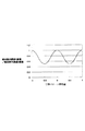
図6は、干渉パターンの移動量と遮蔽格子を透過するX線量の関係を示している。
実線は遮蔽格子に照射されるX線量に対する遮蔽格子を透過するX線量の比であり、横軸は干渉パターンの周期を単位とした干渉パターンの移動量である。点線は比較のために表示した振幅、周期、位相を実線と一致させた理想的な正弦波である。
回折格子の移動量に対する透過部61を通過するX線量の変化は、略正弦波と一致していることから、位相シフト法のアルゴリズムにおいて小さなステップ数(検出回数)を採用しても大きな精度劣化にはならない。
本実施例では計測時間および被検体のX線被曝量を考慮してステップ数を最小の3ステップとし、それに対応したアルゴリズム(3ステップアルゴリズム)を採用している。
FIG. 6 shows the relationship between the amount of movement of the interference pattern and the X-ray dose transmitted through the shielding grating.
The solid line is the ratio of the X-ray dose transmitted through the shielding grid to the X-ray dose irradiated to the shielding grating, and the horizontal axis is the amount of movement of the interference pattern in units of the interference pattern period. The dotted line is an ideal sine wave in which the amplitude, period, and phase displayed for comparison coincide with the solid line.
Since the change in the X-ray dose passing through the
In the present embodiment, the number of steps is set to a minimum of 3 steps in consideration of the measurement time and the X-ray exposure dose of the subject, and an algorithm (3-step algorithm) corresponding thereto is adopted.
図7は、本実施例における被検体の測定ステップを示している。
ステップ110で、遮蔽格子は回折格子との距離Z1が、式(1)を満足するように配置されるので、遮蔽格子6上には明瞭な干渉パターンの強度分布が生じている。
ステップ120で、検出器により強度分布を取得しこれをI0とする。
ここで説明を容易にするため、回折格子4の位置としてP0からP4を以下のように定義する。
即ち、ステップ120の回折格子の位置をP0、P0からx方向に回折格子の周期の1/3周期だけ移動した位置をP1、P0から−x方向に1/3周期だけ移動した位置をP2、とする。
また、P0からy方向に1/3周期だけ移動した位置をP3、P0から−y方向に1/3周期だけ移動した位置をP4とする。なお、x方向およびy方向とは図2に示されている矢印の方向であり、−x方向及び−y方向とは図2に示されている矢印の逆方向である。
FIG. 7 shows a measurement step of the subject in the present embodiment.
In step 110, the amplitude grating is the distance Z 1 to the diffraction grating, since it is arranged so as to satisfy the equation (1), the intensity distribution of the clear interference pattern has occurred on the shielding grating 6.
In step 120, it obtains the intensity distribution by a detector which is referred to as I 0.
Here, for ease of explanation, P 0 to P 4 are defined as the positions of the diffraction grating 4 as follows.
In other words, the position of the diffraction grating in step 120 is moved from P 0 and P 0 in the x direction by 1/3 period of the diffraction grating period, and the position moved from P 1 and P 0 to −x direction by 1/3 period. Let the position be P 2 .
Also, the position moved the position moved by 1/3 cycle from P 0 in the y direction from P3, P0 only 1/3 period -y direction and P 4. The x direction and the y direction are directions of arrows shown in FIG. 2, and the −x direction and the −y direction are directions opposite to the arrows shown in FIG.
ステップ130で、回折格子移動部により回折格子をP1に移動する。ステップ140で、検出器により強度分布を検出しこれをI1とする。
以下、ステップ210まで回折格子4をP2、P3、P4への移動と検出を繰り返し、得られた検出結果を順にI2、I3、I4とする。
ステップ220で、位相シフト法の3ステップアルゴリズムに基づく次に示す式(4)、式(5)よりI0、I1、I2、からx方向の微分位相の位相φxを、同様にI0、I3、I4からy方向の微分位相の位相φyを画素ごとに算出する。
Hereinafter, the movement and detection of the diffraction grating 4 to P 2 , P 3 , and P 4 are repeated until step 210, and the obtained detection results are sequentially referred to as I 2 , I 3 , and I 4 .
In step 220, the differential phase phase φ x in the x direction from I 0 , I 1 , I 2 , based on the following equations (4) and (5) based on the three-step algorithm of the phase shift method, The phase φ y of the differential phase in the y direction is calculated for each pixel from 0 , I 3 , and I 4 .
式(4)、式(5)で算出したφxおよびφyは2πの範囲に位相が畳み込まれた位相(wrapped位相)になっているので、位相接続(unwrap)して各々の方向の微分位相Wx、Wyを得ている。
さらに必要に応じて、ステップ230で得られた直交する2方向の微分位相を積分して得
られた2つの位相分布を合成することで、被検体を透過したX線の位相分布、即ち被検体の位相像を得ることができる。
Since φ x and φ y calculated by Equation (4) and Equation (5) are in a phase (wrapped phase) in which the phase is convoluted in the range of 2π, the phase connection (unwrapped) Differential phases Wx and Wy are obtained.
Furthermore, if necessary, the two phase distributions obtained by integrating the differential phases in the two orthogonal directions obtained in step 230 are synthesized, so that the phase distribution of the X-ray transmitted through the subject, that is, the subject The phase image can be obtained.
以上の説明では、回折格子を最初の撮影時の位置を中心にxおよびyの正負の方向に3
分の1周期移動したが、移動量はこれに限らない。但し、正確な被検体の微分位相像又は位相像を取得するためには、各移動量は等しいことが好ましい。式(4)、式(5)に換えて移動量に準拠した計算式を採用することでφx、φyの算出が可能である。
さらに、回折格子の移動の仕方に関しても、格子位置がx、y両方向で直線的に3点以上並べばよいので、例えば最初の位置P0からx方向に2回移動し、その後y方向に2回移動してもよい。
In the above description, the diffraction grating is 3 in the positive and negative directions of x and y with respect to the position at the time of the first photographing.
Although it has moved by one cycle, the amount of movement is not limited to this. However, in order to obtain an accurate differential phase image or phase image of the subject, it is preferable that the amounts of movement are equal. It is possible to calculate φ x and φ y by adopting a calculation formula based on the movement amount instead of the formula (4) and the formula (5).
Further, regarding the method of moving the diffraction grating, since the grating position may be arranged in three or more points linearly in both the x and y directions, for example, the grating position is moved twice in the x direction from the initial position P 0 and then 2 in the y direction. You may move twice.
[実施例2]
図8−図10を用いて、本発明を実施したX線撮像装置の実施例2について説明する。本実施例は実施例1と回折格子と遮蔽格子が異なり、その他の構成については実施例1と同様である。
図8(a)は、本実施例における回折格子4の一部分をX線源側から見た図である。
本実施例の回折格子は、位相進行部43と位相遅延部44が周期d2で市松格子状に配列したシリコン製の位相変調格子を用いた。位相進行部43を透過したX線と位相遅延部44を透過したX線の位相差はπになるようにシリコンの厚みに差を付けている。
遮蔽格子上に回折格子の干渉パターンが形成されるように、回折格子と遮蔽格子の間隔Z0が式(1)を満足するように遮蔽格子を配置した。但し、N=1/4とした。
図8(b)は本実施例の回折格子を用いた場合に遮蔽格子上に形成される干渉パターンを示しており、その周期d3は、次に示す式(6)で表される。
A second embodiment of the X-ray imaging apparatus embodying the present invention will be described with reference to FIGS. This embodiment is different from the first embodiment in the diffraction grating and the shielding grating, and the other configurations are the same as those in the first embodiment.
FIG. 8A is a view of a part of the diffraction grating 4 in this embodiment as viewed from the X-ray source side.
As the diffraction grating of this example, a phase modulation grating made of silicon in which the
The shielding grating was arranged so that the distance Z 0 between the diffraction grating and the shielding grating satisfied the formula (1) so that the interference pattern of the diffraction grating was formed on the shielding grating. However, N = 1/4.
FIG. 8B shows an interference pattern formed on the shielding grating when the diffraction grating of this embodiment is used, and its period d 3 is expressed by the following equation (6).
ここで、前述したようにZ0はX線源と回折格子の間隔である。
図8(c)は、本実施例における遮蔽格子の一部分をX線源側から見た図である。遮蔽格子は、実施例1と同様に金で作製されており、透過部62が干渉パターンと同じ周期d3で市松格子状に配列している。透過部62は1辺がd2/√2の正方形である。
図9(a)、(b)は遮蔽格子上の干渉パターンを示しており、干渉パターンの明部52のうち透過部62に重なった部分だけが遮蔽格子を経てX線検出器に達する。
X線検出器の画素サイズは、実施例1と同様に遮蔽格子の周期d3に等しくしてあるがd3の整数倍ならそれに限らない。
本実施例では回折格子を面内で移動させることにより干渉パターンと遮蔽格子の相対位置を移動させる。図9(b)は、図9(a)の時から干渉パターンと遮蔽格子の相対位置を干渉パターンの1/3周期のx方向に移動させたときの干渉パターン52と遮蔽格子62の重なり具合を例示している。
回折格子の移動に伴って、透過部62と重なっている干渉パターンの明部52の面積が変化する。この例では、図9(a)の時と比べると図9(b)の時には透過部62と重なっている明部52の面積が小さくなるので、X線検出器に達するX線量も減少する。
Here, as described above, Z 0 is the distance between the X-ray source and the diffraction grating.
FIG. 8C is a view of a part of the shielding grating in this embodiment as viewed from the X-ray source side. Amplitude grating is manufactured in the same gold as Example 1, the
FIGS. 9A and 9B show the interference pattern on the shielding grating, and only the portion of the
The pixel size of the X-ray detector is made equal to the period d 3 of the shielding grating as in the first embodiment, but is not limited to this as long as it is an integral multiple of d 3 .
In this embodiment, the relative position of the interference pattern and the shielding grating is moved by moving the diffraction grating in the plane. FIG. 9B shows the overlapping state of the
As the diffraction grating moves, the area of the
図10は実施例1の図6と同様に、干渉パターンの移動量と透過部62を通過するX線量の関係を示している。
実線は遮蔽格子に照射されるX線量に対するこれを透過するX線量の比であり、横軸は干渉パターン周期を単位とした干渉パターンの移動量である。点線は比較のために表示した振幅、周期、位相を実線と一致させた理想的な正弦波である。本実施例でも実施例1と同様に回折格子の移動量に対する透過部61を通過するX線量の変化が、略正弦波と一致していることから、位相シフト法のアルゴリズムにおいて小さなステップ数を採用しても大きな精度劣化にはならない。本実施例でもステップ数を3にした。
図10と図6を比較して分かるように、本実施例は実施例1に比べて遮蔽格子6を通過するX線量が2倍になっている。そのため、本実施例の方がX線の利用効率が高い。
本実施例における測定ステップは、実施例1で図7を用いて説明したものと同様なので省略する。
FIG. 10 shows the relationship between the amount of movement of the interference pattern and the X-ray dose passing through the
The solid line is the ratio of the X-ray dose transmitted through the shielding grid to the X-ray dose, and the horizontal axis is the amount of movement of the interference pattern in units of the interference pattern period. The dotted line is an ideal sine wave in which the amplitude, period, and phase displayed for comparison coincide with the solid line. In this embodiment as well, as in the first embodiment, the change in the X-ray dose passing through the
As can be seen from a comparison between FIG. 10 and FIG. 6, in this embodiment, the X-ray dose passing through the shielding grating 6 is doubled compared to the first embodiment. Therefore, the use efficiency of X-rays is higher in the present embodiment.
The measurement steps in this embodiment are the same as those described in
[実施例3]
図11(a)−図11(c)を用いて、本発明を実施したX線撮像装置の実施例3について説明する。
本実施例は回折格子に振幅型回折格子を用いたX線撮像装置であり、回折格子と遮蔽格子以外の構成は実施例1と同様である。
図11(a)は、本実施例における回折格子の一部分をX線源側から見た図である。
本実施例に用いられる回折格子はX線を透過する透過部45とX線を遮る遮蔽部46が周期d4で市松格子状に配列している構造を有する。
遮蔽格子上に回折格子の干渉パターンが形成されるように、回折格子と遮蔽格子の間隔Z0が式(1)を満足するように遮蔽格子を配置した。但し、N=1とした。
図11(b)は遮蔽格子上に形成された干渉パターンを示しており、その周期d5は、次に示す式(7)で表される。
A third embodiment of the X-ray imaging apparatus embodying the present invention will be described with reference to FIGS. 11 (a) to 11 (c).
The present embodiment is an X-ray imaging apparatus using an amplitude type diffraction grating as the diffraction grating, and the configuration other than the diffraction grating and the shielding grating is the same as that of the first embodiment.
FIG. 11A is a view of a part of the diffraction grating in the present embodiment as viewed from the X-ray source side.
The diffraction grating used in the present embodiment has a structure in which a
The shielding grating was arranged so that the distance Z 0 between the diffraction grating and the shielding grating satisfied the formula (1) so that the interference pattern of the diffraction grating was formed on the shielding grating. However, N = 1.
FIG. 11B shows an interference pattern formed on the shielding grating, and the period d 5 is expressed by the following equation (7).
図11(c)は、本実施例における遮蔽格子の一部分をX線源側から見た図である。
遮蔽格子は実施例1同様金で作製されており、X線を透過する透過部63とX線を遮る遮蔽部64が、干渉パターンと同じ周期d5で井桁格子状に配列している。透過部63は1辺がd5/2の正方形である。
FIG. 11C is a view of a part of the shielding grating in this embodiment as viewed from the X-ray source side.
Amplitude grating is prepared in Example 1 similarly gold, shielding portion 64 for shielding the
図3、図4と図11(b)、図11(c)を見れば分かるように本実施例の干渉パターンと遮蔽格子は実施例1と同様なので、それらの重なり方、回折格子の移動と遮蔽格子の透過部63を透過するX線量の関係も実施例1と同様である。また、本実施例における測定ステップも、実施例1で図7を用いて説明したものと同様なので省略する。
また、回折格子と遮蔽格子のパターンを入れ替えることもできる。つまり、回折格子を図11(c)のような井桁格子状にして、遮蔽格子を図11(a)のような市松格子状にしても良い。この場合の干渉パターンは図8(b)のようになる。このような回折格子と遮蔽格子を用いた場合、干渉パターンと遮蔽格子が実施例2と同様になるので、干渉パターンの明部と遮蔽格子の透過部の重なり方、回折格子の移動と遮蔽格子の透過部63を透過するX線量の関係も実施例2と同様である。
以上、本発明の好ましい実施形態について説明したが、本発明は上記実施の形態に制限されるものではなく、本発明の精神及び範囲から離脱することなく、様々な変更及び変形が可能である。従って、本発明の範囲を公にするために以下の請求項を添付する。
As can be seen from FIG. 3, FIG. 4, FIG. 11 (b), and FIG. 11 (c), the interference pattern and the shielding grating of this embodiment are the same as those of the first embodiment. The relationship of the X-ray dose transmitted through the
Also, the diffraction grating and shielding grating patterns can be interchanged. That is, the diffraction grating may be formed in a grid pattern as shown in FIG. 11C, and the shielding grating may be formed in a checkered pattern as shown in FIG. The interference pattern in this case is as shown in FIG. When such a diffraction grating and a shielding grating are used, the interference pattern and the shielding grating are the same as in the second embodiment, so that the bright part of the interference pattern and the transmission part of the shielding grating overlap, the movement of the diffraction grating, and the shielding grating. The relationship of the X-ray dose transmitted through the
As mentioned above, although preferable embodiment of this invention was described, this invention is not restrict | limited to the said embodiment, A various change and deformation | transformation are possible, without leaving | separating from the mind and scope of this invention. Therefore, in order to make the scope of the present invention public, the following claims are attached.
1:X線源
2:X線
3:被検体
4:回折格子
5:回折格子移動部
6:遮蔽格子
7:遮蔽格子移動部
8:検出器
9:演算部
1: X-ray source 2: X-ray 3: Subject 4: Diffraction grating 5: Diffraction grating moving unit 6: Shielding grating 7: Shielding grating moving unit 8: Detector 9: Calculation unit
Claims (10)
前記X線を遮蔽する遮蔽部と前記X線を透過する透過部とが2次元に配列しており、前記干渉パターンの前記明部の一部を遮る遮蔽格子と、
前記干渉パターンと前記遮蔽格子の相対位置を交差する2方向に変化させる移動部と、
前記相対位置の変化に対応して前記遮蔽格子を経た前記X線の強度分布を複数回検出する検出器と、
前記検出器による複数回分の検出結果に基づいて被検体の微分位相像又は位相像の少なくともいずれかを算出する演算部を備え、
前記演算部は、
前記複数回分の検出結果の一部を用いて、第1の方向における微分位相像または位相像の少なくともいずれかを算出し、
前記複数回分の検出結果の一部を用いて、前記第1の方向と交差する第2の方向における微分位相像又は位相像の少なくともいずれかを算出し、
前記第1の方向における微分位相像又は位相像の少なくともいずれかの算出と、前記第2の方向における微分位相像又は位相像の少なくともいずれかの算出と、は、前記複数回分の検出結果のうちの一部を共有して行われることを特徴とするX線撮像装置。 A diffraction grating that forms an interference pattern in which a bright part and a dark part are arranged two-dimensionally by diffracting X-rays from an X-ray source;
A shielding part that shields the X-ray and a transmission part that transmits the X-ray are two-dimensionally arranged, and a shielding grating that shields a part of the bright part of the interference pattern;
A moving unit that changes the relative position of the interference pattern and the shielding grating in two intersecting directions ;
A detector for detecting the intensity distribution of the X-rays that has passed through the shielding grating in response to a change in the relative position a plurality of times ;
A calculation unit that calculates at least one of a differential phase image or a phase image of a subject based on a plurality of detection results by the detector,
The computing unit is
Using some of the plurality of times worth of the detection result, and calculating at least one of differential phase image or phase image in the first direction,
Using a part of the detection results for the plurality of times, calculating at least one of a differential phase image or a phase image in a second direction intersecting the first direction,
The calculation of at least one of the differential phase image or the phase image in the first direction and the calculation of at least one of the differential phase image or the phase image in the second direction are among the detection results for the plurality of times. An X-ray imaging apparatus characterized in that a part of the X-ray imaging apparatus is shared .
前記透過部の配置周期が最短となる方向を前記遮蔽格子の周期方向とし、The direction in which the arrangement period of the transmission part is the shortest is the periodic direction of the shielding grating,
前記明部の配置周期が最短となる方向を前記干渉パターンの周期方向とするとき、When the direction in which the arrangement period of the bright part is the shortest is the period direction of the interference pattern,
前記遮蔽格子の周期方向と前記干渉パターンの周期方向とが一致するように、前記回折格子と前記遮蔽格子とが配置されていることを特徴とする請求項1から3のいずれか1項に記載のX線撮像装置。4. The diffraction grating and the shielding grating are arranged so that a periodic direction of the shielding grating and a periodic direction of the interference pattern coincide with each other. X-ray imaging apparatus.
前記位相進行部を透過したX線と前記位相遅延部を透過したX線との位相差はπ/2であり、
前記位相進行部と前記位相遅延部とは市松格子状に配列しており、
前記遮蔽格子は前記遮蔽部と前記透過部とが井桁格子状に配列しており、
前記位相進行部の配置周期が最短となる方向を前記回折格子の周期方向とし、
前記透過部の配置周期が最短となる方向を前記遮蔽格子の周期方向とするとき、
前記回折格子の周期方向と前記遮蔽格子の周期方向とが一致するように前記回折格子と前記遮蔽格子とが配置されていることを特徴とする請求項1から4のいずれか1項に記載のX線撮像装置。 The diffraction grating has a phase advance portion and a phase delay portion,
The phase difference between the X-ray transmitted through the phase advancing unit and the X-ray transmitted through the phase delay unit is π / 2.
The phase advance portion and the phase delay portion are arranged in a checkered lattice pattern,
In the shielding grid, the shielding part and the transmission part are arranged in a grid pattern ,
The direction in which the arrangement period of the phase advancing portion is the shortest is the periodic direction of the diffraction grating,
When the direction in which the arrangement period of the transmission part is the shortest is the periodic direction of the shielding grating,
The said diffraction grating and the said shielding grating are arrange | positioned so that the periodic direction of the said diffraction grating and the periodic direction of the said shielding grating may correspond , The any one of Claim 1 to 4 characterized by the above-mentioned. X-ray imaging device.
前記位相進行部を透過したX線と前記位相遅延部を透過したX線との位相差はπであり、
前記位相進行部と前記位相遅延部とは市松格子状に配列しており、
前記遮蔽格子は前記遮蔽部と前記透過部とが市松格子状に配列しており、
前記位相進行部の配置周期が最短となる方向を前記回折格子の周期方向とし、
前記透過部の配置周期が最短となる方向を前記遮蔽格子の周期方向とするとき、
前記回折格子の周期方向と前記遮蔽格子の周期方向とが45度で交差するように前記回折格子と前記遮蔽格子とが配置されていることを特徴とする請求項1から4のいずれか1項に記載のX線撮像装置。 The diffraction grating has a phase advance portion and a phase delay portion,
The phase difference between the X-ray transmitted through the phase advancing unit and the X-ray transmitted through the phase delay unit is π,
The phase advance portion and the phase delay portion are arranged in a checkered lattice pattern,
In the shielding grid, the shielding portion and the transmission portion are arranged in a checkered lattice shape ,
The direction in which the arrangement period of the phase advancing portion is the shortest is the periodic direction of the diffraction grating,
When the direction in which the arrangement period of the transmission part is the shortest is the periodic direction of the shielding grating,
5. The diffraction grating and the shielding grating are arranged so that a periodic direction of the diffraction grating and a periodic direction of the shielding grating intersect at 45 degrees. X-ray imaging apparatus described in 1.
前記回折格子の前記透過部と前記遮蔽部とが市松格子状に配列しており、
前記遮蔽格子は前記遮蔽部と前記透過部とが井桁格子状に配列しており、
前記回折格子の前記透過部の配置周期が最短となる方向を前記回折格子の周期方向とし、
前記遮蔽格子の前記透過部の配置周期が最短となる方向を前記遮蔽格子の周期方向とするとき、
前記回折格子の周期方向と前記遮蔽格子の周期方向とが一致するように前記回折格子と前記遮蔽格子とが配置されていることを特徴とする請求項1から4のいずれか1項に記載のX線撮像装置。 The diffraction grating has a transmission part that transmits X-rays and a shielding part that blocks X-rays,
The transmission part and the shielding part of the diffraction grating are arranged in a checkered grid pattern,
In the shielding grid, the shielding part and the transmission part are arranged in a grid pattern ,
The direction in which the arrangement period of the transmission part of the diffraction grating is the shortest is the periodic direction of the diffraction grating,
When the direction in which the arrangement period of the transmission parts of the shielding grating is the shortest is the periodic direction of the shielding grating,
The said diffraction grating and the said shielding grating are arrange | positioned so that the periodic direction of the said diffraction grating and the periodic direction of the said shielding grating may correspond , The any one of Claim 1 to 4 characterized by the above-mentioned. X-ray imaging device.
前記回折格子の前記透過部と前記遮蔽部とが井桁格子状に配列しており、
前記遮蔽格子は前記遮蔽部と前記透過部とが市松格子状に配列しており、
前記回折格子の前記透過部の配置周期が最短となる方向を前記回折格子の周期方向とし、
前記遮蔽格子の前記透過部の配置周期が最短となる方向を前記遮蔽格子の周期方向とするとき、
前記回折格子の周期方向と前記遮蔽格子の周期方向とが45度で交差するように前記回折格子と前記遮蔽格子とが配置されていることを特徴とする請求項1から4のいずれか1項に記載のX線撮像装置。 The diffraction grating has a transmission part that transmits X-rays and a shielding part that blocks X-rays,
The transmission part and the shielding part of the diffraction grating are arranged in a grid pattern,
In the shielding grid, the shielding portion and the transmission portion are arranged in a checkered lattice shape ,
The direction in which the arrangement period of the transmission part of the diffraction grating is the shortest is the periodic direction of the diffraction grating,
When the direction in which the arrangement period of the transmission parts of the shielding grating is the shortest is the periodic direction of the shielding grating,
5. The diffraction grating and the shielding grating are arranged so that a periodic direction of the diffraction grating and a periodic direction of the shielding grating intersect at 45 degrees. X-ray imaging apparatus described in 1.
前記検出器は、前記相対位置の変化に対応して前記X線の強度分布を5回検出することで、5回分の検出結果を取得し、
前記演算部は、前記5回分の検出結果に基づいて、前記第1の方向と前記第2の方向の各々における微分位相像または位相像の少なくともいずれかを算出することを特徴とする請求項3に記載のX線撮像装置。 The moving unit changes the relative position in two directions intersecting each other,
The detector acquires the detection result for five times by detecting the X-ray intensity distribution five times in response to the change in the relative position,
The arithmetic unit, based on the five times of the detection result, according to claim 3, characterized in that to calculate at least one of differential phase image or phase image in each of said first direction and said second direction X-ray imaging apparatus described in 1.
前記X線を遮蔽する遮蔽部と前記X線を透過する透過部とが2次元に配列しており、前記干渉パターンの前記明部の一部を遮る遮蔽格子と、A shielding part that shields the X-ray and a transmission part that transmits the X-ray are two-dimensionally arranged, and a shielding grating that shields a part of the bright part of the interference pattern;
前記干渉パターンと前記遮蔽格子の相対位置を交差する2方向に変化させる移動部と、A moving unit that changes the relative position of the interference pattern and the shielding grating in two intersecting directions;
前記相対位置の変化に対応して前記遮蔽格子を経た前記X線の強度分布を複数回検出する検出器と、A detector for detecting the intensity distribution of the X-rays that has passed through the shielding grating in response to a change in the relative position a plurality of times;
前記検出器による複数回分の検出結果に基づいて被検体の微分位相像又は位相像の少なくともいずれかを算出する演算部を備え、A calculation unit that calculates at least one of a differential phase image or a phase image of a subject based on a plurality of detection results by the detector,
前記演算部は、The computing unit is
前記複数回分の検出結果の一部を用いて、第1の方向における微分位相像または位相像の少なくともいずれかを算出し、Using a part of the detection results for the plurality of times, calculating at least one of a differential phase image or a phase image in the first direction,
前記複数回分の検出結果の一部を用いて、前記第1の方向と交差する第2の方向における微分位相像又は位相像の少なくともいずれかを算出し、Using a part of the detection results for the plurality of times, calculating at least one of a differential phase image or a phase image in a second direction intersecting the first direction,
前記遮蔽格子の前記遮蔽部と前記透過部との配置、又は前記干渉パターンの明部と暗部との配置の一方が市松格子状であり、他方が井桁格子状であり、One of the arrangement of the shielding part and the transmission part of the shielding grid, or the arrangement of the bright part and the dark part of the interference pattern is a checkered grid, and the other is a grid pattern.
前記透過部の配置周期が最短となる方向を前記遮蔽格子の周期方向とし、The direction in which the arrangement period of the transmission part is the shortest is the periodic direction of the shielding grating,
前記明部の配置周期が最短となる方向を前記干渉パターンの周期方向とするとき、When the direction in which the arrangement period of the bright part is the shortest is the period direction of the interference pattern,
前記遮蔽格子の周期方向と前記干渉パターンの周期方向とが一致するように、In order for the periodic direction of the shielding grating and the periodic direction of the interference pattern to coincide,
前記回折格子と前記遮蔽格子とが配置されていることを特徴とするX線撮像装置。An X-ray imaging apparatus, wherein the diffraction grating and the shielding grating are arranged.
Priority Applications (1)
| Application Number | Priority Date | Filing Date | Title |
|---|---|---|---|
| JP2011062047A JP5796976B2 (en) | 2010-05-27 | 2011-03-22 | X-ray imaging device |
Applications Claiming Priority (3)
| Application Number | Priority Date | Filing Date | Title |
|---|---|---|---|
| JP2010121225 | 2010-05-27 | ||
| JP2010121225 | 2010-05-27 | ||
| JP2011062047A JP5796976B2 (en) | 2010-05-27 | 2011-03-22 | X-ray imaging device |
Publications (3)
| Publication Number | Publication Date |
|---|---|
| JP2012005820A JP2012005820A (en) | 2012-01-12 |
| JP2012005820A5 JP2012005820A5 (en) | 2014-04-24 |
| JP5796976B2 true JP5796976B2 (en) | 2015-10-21 |
Family
ID=44361228
Family Applications (1)
| Application Number | Title | Priority Date | Filing Date |
|---|---|---|---|
| JP2011062047A Expired - Fee Related JP5796976B2 (en) | 2010-05-27 | 2011-03-22 | X-ray imaging device |
Country Status (3)
| Country | Link |
|---|---|
| US (1) | US9046466B2 (en) |
| JP (1) | JP5796976B2 (en) |
| WO (1) | WO2011149033A1 (en) |
Families Citing this family (18)
| Publication number | Priority date | Publication date | Assignee | Title |
|---|---|---|---|---|
| BR112013009248A2 (en) * | 2010-10-19 | 2019-09-24 | Koninl Philips Electronics Nv | cross-link diffraction for x-ray differential phase contrast imaging, detector arrangement of an x-ray system for phase contrast imaging of an object, x-ray medical imaging system for differential phase contrast imaging, method for differential phase contrast imaging, computer program element for control of an apparatus and computer readable media |
| EP2630476B1 (en) * | 2010-10-19 | 2017-12-13 | Koninklijke Philips N.V. | Differential phase-contrast imaging |
| JP5475737B2 (en) * | 2011-10-04 | 2014-04-16 | 富士フイルム株式会社 | Radiation imaging apparatus and image processing method |
| EP2866665B1 (en) * | 2012-06-27 | 2018-10-31 | Koninklijke Philips N.V. | Grating-based differential phase contrast imaging |
| US9357975B2 (en) | 2013-12-30 | 2016-06-07 | Carestream Health, Inc. | Large FOV phase contrast imaging based on detuned configuration including acquisition and reconstruction techniques |
| US10578563B2 (en) | 2012-12-21 | 2020-03-03 | Carestream Health, Inc. | Phase contrast imaging computed tomography scanner |
| US10096098B2 (en) | 2013-12-30 | 2018-10-09 | Carestream Health, Inc. | Phase retrieval from differential phase contrast imaging |
| EP2934320B1 (en) * | 2012-12-21 | 2020-03-25 | Carestream Health, Inc. | Medical radiographic grating based differential phase contrast imaging |
| DE102013213244A1 (en) * | 2013-07-05 | 2015-01-08 | Siemens Aktiengesellschaft | X-ray system for the high-resolution differential phase-contrast imaging of an examination object |
| EP2827339A1 (en) | 2013-07-16 | 2015-01-21 | Canon Kabushiki Kaisha | Source grating, interferometer, and object information acquisition system |
| JP6495943B2 (en) * | 2014-05-09 | 2019-04-03 | ザ・ジョンズ・ホプキンス・ユニバーシティー | System and method for phase contrast x-ray imaging |
| JP6820870B2 (en) * | 2015-06-30 | 2021-01-27 | コーニンクレッカ フィリップス エヌ ヴェKoninklijke Philips N.V. | Scanning X-ray device with full field detector |
| JP6608246B2 (en) * | 2015-10-30 | 2019-11-20 | キヤノン株式会社 | X-ray diffraction grating and X-ray Talbot interferometer |
| US11259762B2 (en) | 2015-12-25 | 2022-03-01 | Shanghai United Imaging Healthcare Co., Ltd. | Apparatus, system and method for radiation based imaging |
| KR20180047776A (en) | 2016-11-01 | 2018-05-10 | 삼성전자주식회사 | Spectral detector and spectral detecting method using the spectral detector |
| WO2018096759A1 (en) * | 2016-11-22 | 2018-05-31 | 株式会社島津製作所 | X-ray phase imaging device |
| JP7188261B2 (en) * | 2019-04-24 | 2022-12-13 | 株式会社島津製作所 | X-ray phase imaging system |
| CN110833427B (en) * | 2019-11-29 | 2021-01-29 | 清华大学 | Grating imaging system and scanning method thereof |
Family Cites Families (14)
| Publication number | Priority date | Publication date | Assignee | Title |
|---|---|---|---|---|
| WO2004058070A1 (en) | 2002-12-26 | 2004-07-15 | Atsushi Momose | X-ray imaging system and imaging method |
| EP1731099A1 (en) | 2005-06-06 | 2006-12-13 | Paul Scherrer Institut | Interferometer for quantitative phase contrast imaging and tomography with an incoherent polychromatic x-ray source |
| JP2010063646A (en) * | 2008-09-11 | 2010-03-25 | Fujifilm Corp | Radiation phase image radiographing apparatus |
| CN101413905B (en) * | 2008-10-10 | 2011-03-16 | 深圳大学 | X ray differentiation interference phase contrast imaging system |
| WO2010050483A1 (en) * | 2008-10-29 | 2010-05-06 | キヤノン株式会社 | X-ray imaging device and x-ray imaging method |
| JP5238460B2 (en) | 2008-11-17 | 2013-07-17 | 株式会社添島勲商店 | fabric |
| DE102009004702B4 (en) * | 2009-01-15 | 2019-01-31 | Paul Scherer Institut | Arrangement and method for projective and / or tomographic phase-contrast imaging with X-radiation |
| CN102802529B (en) * | 2009-06-16 | 2015-09-16 | 皇家飞利浦电子股份有限公司 | For the bearing calibration of differential contrast imaging |
| JP5631013B2 (en) | 2010-01-28 | 2014-11-26 | キヤノン株式会社 | X-ray imaging device |
| JP5586986B2 (en) | 2010-02-23 | 2014-09-10 | キヤノン株式会社 | X-ray imaging device |
| JP5378335B2 (en) * | 2010-03-26 | 2013-12-25 | 富士フイルム株式会社 | Radiography system |
| JP2012166010A (en) * | 2011-01-26 | 2012-09-06 | Fujifilm Corp | Radiographic imaging apparatus and radiographic image detector |
| US9066704B2 (en) | 2011-03-14 | 2015-06-30 | Canon Kabushiki Kaisha | X-ray imaging apparatus |
| JP2013063099A (en) * | 2011-09-15 | 2013-04-11 | Canon Inc | X-ray imaging device |
-
2011
- 2011-03-22 JP JP2011062047A patent/JP5796976B2/en not_active Expired - Fee Related
- 2011-05-20 US US13/641,966 patent/US9046466B2/en not_active Expired - Fee Related
- 2011-05-20 WO PCT/JP2011/062149 patent/WO2011149033A1/en active Application Filing
Also Published As
| Publication number | Publication date |
|---|---|
| US9046466B2 (en) | 2015-06-02 |
| JP2012005820A (en) | 2012-01-12 |
| US20130034209A1 (en) | 2013-02-07 |
| WO2011149033A1 (en) | 2011-12-01 |
Similar Documents
| Publication | Publication Date | Title |
|---|---|---|
| JP5796976B2 (en) | X-ray imaging device | |
| JP5631013B2 (en) | X-ray imaging device | |
| US9080858B2 (en) | Wavefront measuring apparatus, wavefront measuring method, and computer-readable medium storing program | |
| JP5777360B2 (en) | X-ray imaging device | |
| JP5586986B2 (en) | X-ray imaging device | |
| JP5725870B2 (en) | X-ray imaging apparatus and X-ray imaging method | |
| US20110158493A1 (en) | Analysis method, radiation imaging apparatus using analysis method, and analysis program for executing analysis method | |
| JP5875280B2 (en) | Imaging device using Talbot interference and method for adjusting imaging device | |
| JP2013050441A5 (en) | Wavefront measuring apparatus, wavefront measuring method, program, and X-ray computed tomography apparatus | |
| JP2013063099A (en) | X-ray imaging device | |
| EP2552318A1 (en) | Radiation detection device, radiographic apparatus and radiographic system | |
| US20140286475A1 (en) | Interferometer and object information acquisition system | |
| JP2011153969A5 (en) | ||
| CN105992557B (en) | X-ray Talbot interferometer and X-ray Talbot interferometer system | |
| JP5792961B2 (en) | Talbot interferometer and imaging method | |
| JP6566839B2 (en) | X-ray Talbot interferometer and Talbot interferometer system | |
| JP2013164339A (en) | X-ray imaging device | |
| JP6604772B2 (en) | X-ray Talbot interferometer | |
| JP2017093496A (en) | Imaging device | |
| JP2017090414A (en) | Two-dimensional interference pattern imaging device | |
| JP2013042983A (en) | Tomosynthesis imaging device and imaging method of tomosynthesis image | |
| JP2017083413A (en) | X-ray Talbot interferometer | |
| JP2015227784A (en) | Interferometer |
Legal Events
| Date | Code | Title | Description |
|---|---|---|---|
| RD01 | Notification of change of attorney |
Free format text: JAPANESE INTERMEDIATE CODE: A7421 Effective date: 20131212 |
|
| A521 | Request for written amendment filed |
Free format text: JAPANESE INTERMEDIATE CODE: A523 Effective date: 20140306 |
|
| A621 | Written request for application examination |
Free format text: JAPANESE INTERMEDIATE CODE: A621 Effective date: 20140306 |
|
| A977 | Report on retrieval |
Free format text: JAPANESE INTERMEDIATE CODE: A971007 Effective date: 20141114 |
|
| A131 | Notification of reasons for refusal |
Free format text: JAPANESE INTERMEDIATE CODE: A131 Effective date: 20141216 |
|
| A521 | Request for written amendment filed |
Free format text: JAPANESE INTERMEDIATE CODE: A523 Effective date: 20150216 |
|
| TRDD | Decision of grant or rejection written | ||
| A01 | Written decision to grant a patent or to grant a registration (utility model) |
Free format text: JAPANESE INTERMEDIATE CODE: A01 Effective date: 20150721 |
|
| A61 | First payment of annual fees (during grant procedure) |
Free format text: JAPANESE INTERMEDIATE CODE: A61 Effective date: 20150818 |
|
| R151 | Written notification of patent or utility model registration |
Ref document number: 5796976 Country of ref document: JP Free format text: JAPANESE INTERMEDIATE CODE: R151 |
|
| LAPS | Cancellation because of no payment of annual fees |