EP1803398B1 - Source-detector arrangement for X-ray phase contrast imaging and method therefor - Google Patents
Source-detector arrangement for X-ray phase contrast imaging and method therefor Download PDFInfo
- Publication number
- EP1803398B1 EP1803398B1 EP06016644A EP06016644A EP1803398B1 EP 1803398 B1 EP1803398 B1 EP 1803398B1 EP 06016644 A EP06016644 A EP 06016644A EP 06016644 A EP06016644 A EP 06016644A EP 1803398 B1 EP1803398 B1 EP 1803398B1
- Authority
- EP
- European Patent Office
- Prior art keywords
- focus
- detector arrangement
- arrangement according
- anode
- grating
- Prior art date
- Legal status (The legal status is an assumption and is not a legal conclusion. Google has not performed a legal analysis and makes no representation as to the accuracy of the status listed.)
- Active
Links
- 238000000034 method Methods 0.000 title claims abstract description 20
- 238000003384 imaging method Methods 0.000 title description 4
- 238000010894 electron beam technology Methods 0.000 claims abstract description 38
- 230000005855 radiation Effects 0.000 claims description 49
- 230000010363 phase shift Effects 0.000 claims description 35
- 239000000463 material Substances 0.000 claims description 28
- 230000001427 coherent effect Effects 0.000 claims description 19
- 238000004458 analytical method Methods 0.000 claims description 12
- 230000000694 effects Effects 0.000 claims description 11
- 230000010349 pulsation Effects 0.000 claims description 11
- 230000001419 dependent effect Effects 0.000 claims description 4
- 238000009826 distribution Methods 0.000 claims description 4
- 230000003287 optical effect Effects 0.000 claims description 4
- 230000005684 electric field Effects 0.000 claims description 3
- 230000005693 optoelectronics Effects 0.000 claims 5
- 230000005526 G1 to G0 transition Effects 0.000 claims 1
- 238000013507 mapping Methods 0.000 claims 1
- 238000005259 measurement Methods 0.000 description 9
- 238000010521 absorption reaction Methods 0.000 description 6
- 238000006073 displacement reaction Methods 0.000 description 6
- 230000006870 function Effects 0.000 description 6
- 230000017525 heat dissipation Effects 0.000 description 4
- 238000004519 manufacturing process Methods 0.000 description 3
- 238000003325 tomography Methods 0.000 description 3
- 239000010405 anode material Substances 0.000 description 2
- 238000000354 decomposition reaction Methods 0.000 description 2
- 238000011161 development Methods 0.000 description 2
- 230000018109 developmental process Effects 0.000 description 2
- 229910003460 diamond Inorganic materials 0.000 description 2
- 239000010432 diamond Substances 0.000 description 2
- 230000004907 flux Effects 0.000 description 2
- 239000000203 mixture Substances 0.000 description 2
- 230000035515 penetration Effects 0.000 description 2
- 230000000737 periodic effect Effects 0.000 description 2
- 238000005070 sampling Methods 0.000 description 2
- 210000004872 soft tissue Anatomy 0.000 description 2
- 238000004846 x-ray emission Methods 0.000 description 2
- 230000005461 Bremsstrahlung Effects 0.000 description 1
- RYGMFSIKBFXOCR-UHFFFAOYSA-N Copper Chemical compound [Cu] RYGMFSIKBFXOCR-UHFFFAOYSA-N 0.000 description 1
- ZOKXTWBITQBERF-UHFFFAOYSA-N Molybdenum Chemical compound [Mo] ZOKXTWBITQBERF-UHFFFAOYSA-N 0.000 description 1
- 230000001133 acceleration Effects 0.000 description 1
- XAGFODPZIPBFFR-UHFFFAOYSA-N aluminium Chemical compound [Al] XAGFODPZIPBFFR-UHFFFAOYSA-N 0.000 description 1
- 229910052782 aluminium Inorganic materials 0.000 description 1
- 238000013459 approach Methods 0.000 description 1
- 229910052790 beryllium Inorganic materials 0.000 description 1
- ATBAMAFKBVZNFJ-UHFFFAOYSA-N beryllium atom Chemical compound [Be] ATBAMAFKBVZNFJ-UHFFFAOYSA-N 0.000 description 1
- 239000011248 coating agent Substances 0.000 description 1
- 238000000576 coating method Methods 0.000 description 1
- 238000002591 computed tomography Methods 0.000 description 1
- 239000012141 concentrate Substances 0.000 description 1
- 238000009548 contrast radiography Methods 0.000 description 1
- 238000001816 cooling Methods 0.000 description 1
- 229910052802 copper Inorganic materials 0.000 description 1
- 239000010949 copper Substances 0.000 description 1
- 238000013461 design Methods 0.000 description 1
- 238000001514 detection method Methods 0.000 description 1
- 238000010586 diagram Methods 0.000 description 1
- 238000007373 indentation Methods 0.000 description 1
- 230000005865 ionizing radiation Effects 0.000 description 1
- 238000002955 isolation Methods 0.000 description 1
- 238000002844 melting Methods 0.000 description 1
- 230000008018 melting Effects 0.000 description 1
- 229910052750 molybdenum Inorganic materials 0.000 description 1
- 239000011733 molybdenum Substances 0.000 description 1
- 238000002601 radiography Methods 0.000 description 1
- 210000002023 somite Anatomy 0.000 description 1
- 230000003068 static effect Effects 0.000 description 1
- 230000008961 swelling Effects 0.000 description 1
- 230000005469 synchrotron radiation Effects 0.000 description 1
- 238000012360 testing method Methods 0.000 description 1
- 230000008646 thermal stress Effects 0.000 description 1
- WFKWXMTUELFFGS-UHFFFAOYSA-N tungsten Chemical compound [W] WFKWXMTUELFFGS-UHFFFAOYSA-N 0.000 description 1
- 229910052721 tungsten Inorganic materials 0.000 description 1
- 239000010937 tungsten Substances 0.000 description 1
Images


Classifications
-
- A—HUMAN NECESSITIES
- A61—MEDICAL OR VETERINARY SCIENCE; HYGIENE
- A61B—DIAGNOSIS; SURGERY; IDENTIFICATION
- A61B6/00—Apparatus or devices for radiation diagnosis; Apparatus or devices for radiation diagnosis combined with radiation therapy equipment
-
- A—HUMAN NECESSITIES
- A61—MEDICAL OR VETERINARY SCIENCE; HYGIENE
- A61B—DIAGNOSIS; SURGERY; IDENTIFICATION
- A61B6/00—Apparatus or devices for radiation diagnosis; Apparatus or devices for radiation diagnosis combined with radiation therapy equipment
- A61B6/42—Arrangements for detecting radiation specially adapted for radiation diagnosis
- A61B6/4291—Arrangements for detecting radiation specially adapted for radiation diagnosis the detector being combined with a grid or grating
-
- A—HUMAN NECESSITIES
- A61—MEDICAL OR VETERINARY SCIENCE; HYGIENE
- A61B—DIAGNOSIS; SURGERY; IDENTIFICATION
- A61B6/00—Apparatus or devices for radiation diagnosis; Apparatus or devices for radiation diagnosis combined with radiation therapy equipment
- A61B6/48—Diagnostic techniques
- A61B6/484—Diagnostic techniques involving phase contrast X-ray imaging
-
- A—HUMAN NECESSITIES
- A61—MEDICAL OR VETERINARY SCIENCE; HYGIENE
- A61B—DIAGNOSIS; SURGERY; IDENTIFICATION
- A61B6/00—Apparatus or devices for radiation diagnosis; Apparatus or devices for radiation diagnosis combined with radiation therapy equipment
- A61B6/02—Arrangements for diagnosis sequentially in different planes; Stereoscopic radiation diagnosis
- A61B6/03—Computed tomography [CT]
- A61B6/032—Transmission computed tomography [CT]
-
- A—HUMAN NECESSITIES
- A61—MEDICAL OR VETERINARY SCIENCE; HYGIENE
- A61B—DIAGNOSIS; SURGERY; IDENTIFICATION
- A61B6/00—Apparatus or devices for radiation diagnosis; Apparatus or devices for radiation diagnosis combined with radiation therapy equipment
- A61B6/40—Arrangements for generating radiation specially adapted for radiation diagnosis
- A61B6/4021—Arrangements for generating radiation specially adapted for radiation diagnosis involving movement of the focal spot
- A61B6/4028—Arrangements for generating radiation specially adapted for radiation diagnosis involving movement of the focal spot resulting in acquisition of views from substantially different positions, e.g. EBCT
-
- A—HUMAN NECESSITIES
- A61—MEDICAL OR VETERINARY SCIENCE; HYGIENE
- A61B—DIAGNOSIS; SURGERY; IDENTIFICATION
- A61B6/00—Apparatus or devices for radiation diagnosis; Apparatus or devices for radiation diagnosis combined with radiation therapy equipment
- A61B6/44—Constructional features of apparatus for radiation diagnosis
- A61B6/4429—Constructional features of apparatus for radiation diagnosis related to the mounting of source units and detector units
- A61B6/4435—Constructional features of apparatus for radiation diagnosis related to the mounting of source units and detector units the source unit and the detector unit being coupled by a rigid structure
- A61B6/4441—Constructional features of apparatus for radiation diagnosis related to the mounting of source units and detector units the source unit and the detector unit being coupled by a rigid structure the rigid structure being a C-arm or U-arm
-
- G—PHYSICS
- G21—NUCLEAR PHYSICS; NUCLEAR ENGINEERING
- G21K—TECHNIQUES FOR HANDLING PARTICLES OR IONISING RADIATION NOT OTHERWISE PROVIDED FOR; IRRADIATION DEVICES; GAMMA RAY OR X-RAY MICROSCOPES
- G21K2201/00—Arrangements for handling radiation or particles
- G21K2201/06—Arrangements for handling radiation or particles using diffractive, refractive or reflecting elements
-
- G—PHYSICS
- G21—NUCLEAR PHYSICS; NUCLEAR ENGINEERING
- G21K—TECHNIQUES FOR HANDLING PARTICLES OR IONISING RADIATION NOT OTHERWISE PROVIDED FOR; IRRADIATION DEVICES; GAMMA RAY OR X-RAY MICROSCOPES
- G21K2207/00—Particular details of imaging devices or methods using ionizing electromagnetic radiation such as X-rays or gamma rays
- G21K2207/005—Methods and devices obtaining contrast from non-absorbing interaction of the radiation with matter, e.g. phase contrast
-
- H—ELECTRICITY
- H01—ELECTRIC ELEMENTS
- H01J—ELECTRIC DISCHARGE TUBES OR DISCHARGE LAMPS
- H01J2235/00—X-ray tubes
- H01J2235/08—Targets (anodes) and X-ray converters
- H01J2235/086—Target geometry
Definitions
- the invention relates to a focus-detector arrangement of an X-ray apparatus for producing projective or tomographic phase contrast recordings of an examination subject with a radiation source arranged on a first side of the examination subject, which generates a bundle of coherent beams of grid-like origin, one on the opposite second side of the examination subject arranged in the beam path phase grating, which generates an interference pattern of the X-radiation in a predetermined energy range of the X-radiation, and an analysis-detector system which detects at least the interference pattern generated by the phase grating locally with respect to its phase shift.
- the invention also relates to a method for producing projective or tomographic X-ray phase contrast recordings with the above-mentioned focus detector arrangement.
- Such focus-detector arrangements for producing projective or tomographic phase-contrast images of an examination subject or such methods are generally known. Exemplary is on the EP 1 447 046 A1 and the unpublished German patent applications with the file number 10 2006 017 290 .6, 10 2006 015 358.8, 10 2006 017 291.4, 10 2006 015 356.1 and 10 2006 015 355.3 directed.
- the document "Hard X-ray phase imaging and tomography with a grating interferometer" by Weitkamp et al. represents the closest prior art to the independent claim 1.
- phase contrast radiography or phase contrast tomography For such phase contrast radiography or phase contrast tomography, the phase shift caused by the object must be evaluated.
- analogous to X-ray radiography or X-ray tomography both projective images of the phase shift or a plurality of projective images tomographic representations of the phase shift, which is effected by a volume element can be calculated.
- phase shifts to produce projective or tomographic images can be measured by use of interferometric grids.
- interferometric measuring methods reference is also made to the previously cited documents.
- a test object is irradiated by a coherent X-radiation, then passed through a grating with a period adapted to the wavelengths of the radiation, resulting in an interference pattern, which is dependent on the radiation shift occurring.
- This interference pattern is measured by a subsequent analysis-detector arrangement, so that the phase shift can be determined.
- the method described above requires a sufficient degree of spatial coherence in the radiation used. This can be achieved, for example, by means of an extremely small focus, whereby the achievable dose rate is scarcely usable here for medical applications because of the too long required irradiation time. Another possibility is the use of synchrotron radiation. Such apparatuses are far too expensive in practice.
- a focus with a conventionally large focal spot as it is known in the field of known computed tomography, and to arrange a so-called source grid between the focus and the examination object.
- the slots of this source grid generate a field of individually coherent beams of a given energy whose dose rate is sufficient to produce the per se known interference pattern with the aid of a phase grating arranged behind the object in the beam direction.
- a problem with this type of focus-detector combinations is that when using such source grids still a relatively high dose content is generated by radiation that does not count to quasi-coherent radiation and thus on the one hand provides a high background noise and on the other hand unnecessary radiation exposure of the examined patient leads.
- the present inventors have realized that it is possible to perform the effect of generating a bundle of quasi-coherent beams of latticed origin through a source grid also directly on an anode by producing stripe-shaped regions having a different emission of radiation.
- a movement of the source grid can thus be simulated.
- At least the surface of the anode has strip-shaped regions of different material in the region of an electron beam focal spot generated for operation of the x-ray tube.
- means for displacement of the anode preferably perpendicular to the strip longitudinal direction, are provided, said means for displacing the strip-shaped regions, preferably acting perpendicular to the strip longitudinal direction, are provided.
- an electron mask with strip-like openings between cathode and anode which are imaged on the anode and thereby lead to strip-like regions of different radiation emission on the anode.
- at least one electron-optical lens can be arranged between the electron mask and the anode and / or between the cathode and the electron mask.
- the electron-optical lens may be formed as a magnetic field lens or as an electric field lens.
- means for displacing the electron mask preferably for displacement perpendicular to the strip longitudinal direction, be provided.
- means for varying at least one electron-optical lens can be provided, which causes a displacement of the mask image on the anode, preferably perpendicular to the strip longitudinal direction.
- the anode has at least in the region of an electron beam focal spot generated for operation of the X-ray tube strip-shaped heights and depths, causing shading or due to the then forming field lines, the electrons preferably meet at the heights on the anode and there preferably produce X-rays.
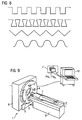
- the course of the heights and depths may, for example, be wave-shaped, preferably sinusoidal, or also sawtooth-like, trapezoidal or rectangular.
- the anode can preferably be designed as a rotary anode because of the better cooling situation.
- the rotary anode depending on the requirements in the direction of rotation aligned strips, strips on a conical surface of the rotary anode or strip on a cylinder surface of the rotary anode can have.
- the strips of the rotary anode can have an axial direction component which is axial relative to the axis of rotation of the rotary anode, and means for generating and controlling a stroboscopic pulsation of the tube current can be provided.
- means for tuning the frequency and phase of the pulsation of the tube current and the rotational speed can be provided such that the position of the strips of different material in the maximum of the tube current remains unchanged relative to the x-ray tube.
- the means for tuning the frequency and phase of the pulsation of the tube current and the rotational speed can also be designed such that the position of the strips of different material in the maximum of the tube current relative to the x-ray tube, preferably stepwise, in the direction of rotation for measuring the phase shift at fixed phase grating and stationary Analytical grid wanders. As a result, the known per se movement of the source grid is modeled.
- the strips should be arranged parallel to the grid lines of the phase grating.
- the strips may also have an angle, preferably 45 °, to the radial direction.
- the x-ray tube comprise means for generating and deflecting a bundled one Electron beam, wherein the electron beam is moved on an anode surface along at least one imaginary grid line.
- a plurality of grid lines can be provided and the electron beam can jump from grid line to grid line.
- the grid lines can have spacings between one another, which represent an integer multiple of a basic distance.
- the periodicity of the grid is maintained, but at the same time allows different distances.
- the simplest variant of this embodiment can simply be considered as a periodic lattice in which all the lattice lines extend in parallel at the same distance, with the electron beam scanning the lattice lines one after the other or in any order.
- a rotary anode can be used here for better heat dissipation.
- this rotary anode may have a conical anode surface, wherein the lines are aligned on this surface radially or tangentially to the axis of rotation of the rotary anode.
- the rotary anode can have a cylindrical anode surface, wherein the lines on this surface are aligned parallel or perpendicular to the axis of rotation. It is also possible to align the lines at an angle to the axis of rotation and the radial direction.
- the inventors propose that the sampling period, ie the period of one revolution, of the electron beam is small (factor 1/2 - 1/10), preferably very small (factor ⁇ 1/10), against the sampling period of Detector in the analysis detector system.
- the means for deflecting the electron beam may be designed such that the movement of a source grating for determining the phase shift is replicated.
- the focus-detector arrangements described above can be used without final listing, for example, in X-ray system for producing projective phase contrast recordings, in X-ray C-arm system for producing projective or tomographic phase contrast recordings or in X-ray CT system for generating tomographic phase contrast recordings.
- the inventors also propose a method for producing projective or tomographic X-ray phase contrast images of an examination object with the aid of a focus detector arrangement comprising an X-ray radiation source, a phase grating and an analysis detector system, in which a bundle of coherent beams of lattice origin is generated by an anode having stripe-shaped regions of different emission radiation that are parallel to the grating lines of the phase grating.
- the strips of different radiation emission can be generated by strip-shaped regions of different material.
- the strips of different radiation emission can also be generated by strip-shaped regions of different height and depth.
- a rotary anode may be used to effect better heat dissipation and / or to simulate movement of the replaced source grating, preferably by operating the strips of the rotary anode with a directional component axial to the axis of rotation of the rotary anode and strobing the tube current in a stroboscopic manner.
- the frequency and phase of the pulsation of the tube current to the rotational frequency of the rotary anode can thus be selectively coordinated so that the position of the stripes of different radiation emission remains unchanged at the maximum of the tube current relative to the X-ray tube or that the movement of a source grid is simulated to determine the phase shift.
- the inventors also propose that, to produce a bundle of coherent beams, an electron beam is moved on the anode surface in accordance with the grating lines of an X-ray optical grating, with the grating lines of the simulated source grating remaining stationary.
- an electron beam is moved on the anode surface in accordance with the grating lines of a source X-ray grating, simulating the movement of the grating lines of the simulated source grating to determine the phase shift.
- the course of the intensity maxima forming strips or slots may be aligned parallel tangential or oblique to the axis of rotation.
- the FIG. 1 shows a coming from the focus quasi-coherent radiation or coming from a source grid individually coherent radiation, which penetrates a sample P, wherein it comes after the penetration of the sample P to phase shift phenomena.
- an interference pattern which is represented by the gray shading is generated, which leads with the aid of the grating G 2 to the subsequent detector D 1 and its detector elements to different radiation intensities per detector element, wherein in a so-called Talbotabstand an interference pattern, a so-called Moire pattern, trains.
- the detector element E i as a function of an offset x G of the analysis grid G 2 and carries the intensity I (E i (X G )) as a function of the offset x G on the intensity I
- I E i (X G )
- the function I (E i) is established for the various detector elements which ultimately form the spatial x-ray beam between the focus and the respective detector element (x G )) or I (E j (x G )) approximate. From the functions, the phase shift ⁇ and the relative phase shift ⁇ ij between the detector elements can be determined for each detector element.
- the phase shift per beam can be determined by at least three measurements with each offset analysis grid, from which the pixel values of a projective image can either be calculated directly in the case of projective X-ray images or projections are created in the case of a CT examination whose pixel values correspond to the phase shift, so that it can be calculated therefrom with the aid of known reconstruction methods, which volume element in the examination object is to be attributed which proportion of the measured phase shift. From this, sectional images or volume data are calculated which reflect the local effect of the examined object with respect to the phase shift of an X-ray radiation. Since even slight differences in the composition exert a strong effect on the phase shift, this can be very detailed and high-contrast volume data of relatively relatively similar materials, in particular of soft tissue, play.
- This variant of the detection of phase shifts of the X-rays, which penetrate an examination subject, with the aid of a multiple offset analysis grid and measurement of the radiation intensity on a detector element behind the analysis grid requires that at least three measurements of each X-ray beam must be performed at each shifted analysis grid.
- a field (array) of individually coherent radiation is not generated by a source grid behind a flat focus, but instead produced by a grid-like configuration of the electron beam focal spot on the anode for reproducing such a grid.
- This array of individually coherent but mutually incoherent sources can be made by generating a corresponding intensity distribution of the x-rays emitted by the x-ray tube. This can be achieved in different ways:
- a first possible embodiment is in the FIG. 3 shown in which a relatively wide electron beam 14 is directed to an anode base plate 12.
- the anode base plate 12 is made of a low Z material, which should preferably have high thermal conductivity, high melting point, good stability, and sufficient current conductivity.
- a low Z material for example, aluminum, beryllium or diamond can be used here.
- the current conductivity can be achieved, for example, by doping or coating the material with a conductive layer.
- a material with a high Z value for example copper, molybdenum or tungsten, should be present.
- the strips 13 made of a high Z material thus emit relatively high intensity X-rays.
- the characteristic lines of the material can be emitted by a suitable choice of the material according to the acceleration voltage present, while the surrounding material preferably has no characteristic lines in this area. It should be noted that even this material emits characteristic X-rays, but their energy is relatively low and is already largely absorbed by the tube window. In addition, the effectiveness of the production of Bremsstrahlung is less, since this is proportional to the Z value. Thus, in areas where the anode baseplate is struck by the electron beam, X-rays are also produced, but significantly less overall Intensity than in the strip-shaped areas of high Z value.
- an X-ray tube with rotating anode can be used, which provides an increased heat capacity for a higher X-ray flux.
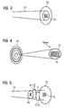
- many radially oriented stripes may be distributed along a whole circular path. An example of this is in the FIG. 4 shown.
- the elemental sources are constantly shifting with respect to the interferometer grating because of anode rotation.
- This effect can be used on the one hand to simulate a moving source grid for phase determination, on the other hand, this effect can also be avoided by the electron beam and thus the X-ray emission synchronously pulsed to the anode rotation such that its maximum is always achieved when the stripes have moved on for a period.
- the position of the elemental X-ray emitters then appears to be static when viewed from the detector.
- a portion of the incident on the anode plate 16 electron beam 14 using an electron mask 15, as shown in the FIG. 5 sketched is to crop.
- the electron mask 15 can be connected to a certain potential (voltage). This voltage should be low enough to avoid that the incident electrons already reach too high a kinetic energy, whereby the temperature of the electron mask 15 would rise too much and in addition unwanted secondary X-radiation would be generated. This can be avoided, for example, by applying the electron mask with a voltage below the energy to which the interferometer structure is set.
- this electron mask can be advantageously used as a focusing electrode, which focuses the generated electrons on the anode surface.
- the mask can also be connected to a well-defined control voltage (focusing voltage).
- focusing voltage focusing voltage
- the electron beam impinging on the anode can be deflected correspondingly using an electric field generated by the optional electrode plates 17.1 and 17.2 or a magnetic field, ie an electron optics.
- the electron beam can be switched on and off by such an arrangement.
- Exemplary and highly schematic is such an arrangement in the FIG. 6 shown in the case of electrostatic optics.
- a collimated electron beam 14 is shown, which is controlled by two mutually perpendicular plate electrode pairs 17.1, 17.2 and 18.1, 18.2 with respect to its deflection in its direction.
- the electron beam can scan the anode in a line-like manner with the desired spacing of the lines, similar to the scan of a television image, thereby producing the desired X-radiation.
- the electron beam can scan the anode in a line-like manner with the desired spacing of the lines, similar to the scan of a television image, thereby producing the desired X-radiation.
- a stripe pattern consisting of at least one or more stripes corresponding to the lines of a source lattice is generated. In terms of time, the function of a source grid is thereby also achieved.
- pulsation of the electron beam it should be noted that these are, for example, by a specific periodic change in the cathode temperature, fast and strong deflection of the electron beam, field emission cathodes, electrically controllable electron emission, photoemission cathodes, cathodes with light- or laser-induced emission, streak tubes, gated electron tubes a triode or pentode or by traveling wave tubes can be done.
- a linear focus and only a single axis deflection may be applied perpendicular thereto.
- the hot spot temperature is distributed along the line-shaped focus.
- Another possibility for improvement is the use of an X-ray tube with rotating anode, optionally with electron beam deflection.
- the hot spot temperature is distributed along a longer circular track.
- the rotation with sufficient speed smears the thermal stress homogeneously across the path of the electron beam.
- the maximum brilliance of an X-ray tube is limited by the derivative of the heat generated at the focal point. If an X-ray source consisting of a plurality of strips is used, corresponding to the above-described embodiments according to the invention, an improved heat dissipation on the anode surface results. Unlike an arrangement that consists of a flat focal point and source lattice, no or less heat is produced at the areas between the strips, so that therefore a higher brilliance of the radiation can be achieved.
- FIG. 7 Another embodiment of an anode 12 according to the invention is in the FIG. 7 shown.
- This has indentations 19, which the anode material relative to the approaching electron e - shade, while on the plateaus 20 of the anode, the electrons e - striking increases. Accordingly arise on the anode surface strip-shaped areas with increased and reduced swelling intensity of generated braking and X-rays ⁇ .
- the source intensity Q of the X-ray radiation is plotted as a stair line 21 with respect to a desired x-axis.
- other design variants such as groove-shaped depressions or a wave or sinusoidal surface profile, are possible. It is only essential here that X-radiation with different intensity is formed on the anode surface.
- Four examples of other possible surface courses are in the FIG. 8 shown in cross section.
- FIG. 9 A complete computer CT system for using the focus detector system according to the invention or carrying out the method according to the invention is disclosed in US Pat FIG. 9 shown.
- the x-ray tube 2 in this case contains a multi-strip focus according to the invention, which generates quasi-coherent x-rays.
- In the beam path of the first focus-detector system is still an X-ray optical grating system, as for example in the FIG.
- the control of the CT system is carried out by a computing and control unit 10 in which programs Prg 1 to Prg n are stored in a memory 11, which carry out the method described above in operation and also control the X-ray tube according to the invention with its multi-strip focus and off Reconstruct tomographic images corresponding to the measured radiation-dependent phase shifts.
- a second focus-detector system can be arranged in the gantry housing. This is in the FIG. 9 indicated by the dashed lines X-ray tube 4 and the dashed detector 5 shown.
- phase shifts of the X-radiation can be measured, but these also continue to be used for the conventional measurement of the radiation absorption and reconstruction of corresponding absorption receptacles are suitable.
- combined absorption and phase contrast recordings can also be generated.
Landscapes
- Health & Medical Sciences (AREA)
- Life Sciences & Earth Sciences (AREA)
- Medical Informatics (AREA)
- Engineering & Computer Science (AREA)
- Radiology & Medical Imaging (AREA)
- Molecular Biology (AREA)
- Biophysics (AREA)
- Nuclear Medicine, Radiotherapy & Molecular Imaging (AREA)
- Optics & Photonics (AREA)
- Pathology (AREA)
- Physics & Mathematics (AREA)
- Biomedical Technology (AREA)
- Heart & Thoracic Surgery (AREA)
- High Energy & Nuclear Physics (AREA)
- Surgery (AREA)
- Animal Behavior & Ethology (AREA)
- General Health & Medical Sciences (AREA)
- Public Health (AREA)
- Veterinary Medicine (AREA)
- Apparatus For Radiation Diagnosis (AREA)
- X-Ray Techniques (AREA)
- Analysing Materials By The Use Of Radiation (AREA)
Abstract
Description
Die Erfindung betrifft eine Fokus-Detektor-Anordnung einer Röntgenapparatur zur Erzeugung projektiver oder tomographischer Phasenkontrastaufnahmen von einem Untersuchungsobjekt mit einer auf einer ersten Seite des Untersuchungsobjektes angeordneten Strahlungsquelle, welche ein Bündel von kohärenten Strahlen mit gitterartigem Ursprung erzeugt, einem auf der gegenüberliegenden zweiten Seite des Untersuchungsobjektes im Strahlengang angeordnetes Phasengitter, welches ein Interferenzmuster der Röntgenstrahlung in einem vorbestimmten Energiebereich der Röntgenstrahlung erzeugt, und ein Analyse-Detektor-System, welches zumindest das vom Phasengitter erzeugte Interferenzmuster örtlich bezüglich seiner Phasenverschiebung detektiert. Außerdem betrifft die Erfindung auch ein Verfahren zur Erzeugung projektiver oder tomographischer Röntgen-Phasenkontrastaufnahmen mit der oben genannten Fokus-Detektor-Anordnung.The invention relates to a focus-detector arrangement of an X-ray apparatus for producing projective or tomographic phase contrast recordings of an examination subject with a radiation source arranged on a first side of the examination subject, which generates a bundle of coherent beams of grid-like origin, one on the opposite second side of the examination subject arranged in the beam path phase grating, which generates an interference pattern of the X-radiation in a predetermined energy range of the X-radiation, and an analysis-detector system which detects at least the interference pattern generated by the phase grating locally with respect to its phase shift. Moreover, the invention also relates to a method for producing projective or tomographic X-ray phase contrast recordings with the above-mentioned focus detector arrangement.
Solche Fokus-Detektor-Anordnungen zur Erzeugung projektiver oder tomographischer Phasenkontrastaufnahmen von einem Untersuchungsobjekt beziehungsweise solche Verfahren sind allgemein bekannt. Beispielhaft wird auf die
Für die Bildgebung durch ionisierende Strahlen, insbesondere durch Röntgenstrahlen können grundsätzlich zwei Effekte betrachtet werden, die beim Durchtritt der Strahlung durch Materie auftreten, nämlich die Absorption und die Phasenverschiebung der durch ein Untersuchungsobjekt durchtretenden Strahlung. Es ist auch bekannt, dass der Effekt der Phasenverschiebungen beim Durchtritt eines Strahles durch ein Untersuchungsobjekt wesentlich stärker auf geringere Unterschiede in der Zusammensetzung der durchdrungenen Materie reagiert, als die Absorptionseffekte.For the imaging by ionizing radiation, in particular by X-rays, basically two effects can be considered, which occur during the passage of the radiation through matter, namely the absorption and the phase shift of the radiation passing through an examination object. It is also known that the effect of phase shifts When a beam passes through an object to be examined, it reacts much more strongly to smaller differences in the composition of the penetrated matter than the absorption effects.
Für eine solche Phasenkontrastradiographie oder Phasenkontrasttomographie muss die vom Objekt verursachte Phasenverschiebung ausgewertet werden. Hierbei können analog zur Röntgenradiographie beziehungsweise Röntgentomographie sowohl projektive Bilder der Phasenverschiebung oder auch eine Vielzahl von projektiven Bildern tomographischer Darstellungen der Phasenverschiebung, die durch ein Volumenelement bewirkt wird, berechnet werden.For such phase contrast radiography or phase contrast tomography, the phase shift caused by the object must be evaluated. In this case, analogous to X-ray radiography or X-ray tomography both projective images of the phase shift or a plurality of projective images tomographic representations of the phase shift, which is effected by a volume element can be calculated.
Derartige Phasenverschiebungen zur Erzeugung projektiver oder tomographischer Aufnahmen können durch die Verwendung durch interferometrische Gitter gemessen werden. Bezüglich dieser interferometrischen Messmethoden wird ebenfalls auf die zuvor zitierte Schriften verwiesen. Bei diesen Methoden wird ein Untersuchungsobjekt von einer kohärenten Röntgenstrahlung durchstrahlt, anschließend durch ein Gitter mit einer auf die Wellenlängen der Strahlung angepassten Periode geführt, wodurch ein Interferenzmuster entsteht, welches abhängig von der auftretenden Strahlungsverschiebung ist. Dieses Interferenzmuster wird durch eine anschließende Analyse-Detektor-Anordnung ausgemessen, so dass die Phasenverschiebung bestimmt werden kann.Such phase shifts to produce projective or tomographic images can be measured by use of interferometric grids. With respect to these interferometric measuring methods, reference is also made to the previously cited documents. In these methods, a test object is irradiated by a coherent X-radiation, then passed through a grating with a period adapted to the wavelengths of the radiation, resulting in an interference pattern, which is dependent on the radiation shift occurring. This interference pattern is measured by a subsequent analysis-detector arrangement, so that the phase shift can be determined.
Das oben beschriebene Verfahren erfordert einen ausreichenden Grad an räumlicher Kohärenz in der verwendeten Strahlung. Dies kann beispielsweise durch einen extrem kleinen Fokus erreicht werden, wobei hier die erreichbare Dosisleistung wegen der zu langen erforderlichen Bestrahlungszeit für medizinische Anwendungen kaum nutzbar ist. Eine andere Möglichkeit ist die Verwendung von Synchrotronstrahlung. Derartige Apparaturen sind in der Praxis viel zu aufwendig. Schließlich wird im genannten Stand der Technik auch vorgeschlagen, einen Fokus mit einem konventionell großen Brennfleck zu verwenden, wie er im Bereich der bekannten Computertomographie bekannt ist, und zwischen Fokus und Untersuchungsobjekt ein sogenanntes Quellengitter anzuordnen. Die Schlitze dieses Quellengitters erzeugen ein Feld von individuell kohärenten Strahlen einer bestimmten Energie, deren Dosisleistung ausreicht, um mit Hilfe eines in Strahlrichtung hinter dem Objekt angeordneten Phasengitter das an sich bekannte Interferenzmuster zu erzeugen.The method described above requires a sufficient degree of spatial coherence in the radiation used. This can be achieved, for example, by means of an extremely small focus, whereby the achievable dose rate is scarcely usable here for medical applications because of the too long required irradiation time. Another possibility is the use of synchrotron radiation. Such apparatuses are far too expensive in practice. Finally, it is also proposed in the cited prior art to use a focus with a conventionally large focal spot, as it is known in the field of known computed tomography, and to arrange a so-called source grid between the focus and the examination object. The slots of this source grid generate a field of individually coherent beams of a given energy whose dose rate is sufficient to produce the per se known interference pattern with the aid of a phase grating arranged behind the object in the beam direction.
Auf diese Weise ist es möglich, Strahlungsquellen zu verwenden, die Ausdehnungen besitzen, die normalen Röntgenröhren in CT-Systemen beziehungsweise Durchlicht-Röntgen-Systemen entsprechen, so dass zum Beispiel im Bereich der allgemeinen medizinischen Diagnostik nun mit Hilfe von Röntgen-Geräten auch gut differenzierte Weichteilaufnahmen gemacht werden können.In this way, it is possible to use radiation sources that have expansions that correspond to normal x-ray tubes in CT systems or transmitted-light x-ray systems, so that, for example, in the field of general medical diagnostics now well-differentiated with the help of x-ray equipment Soft tissue shots can be made.
Ein Problem bei dieser Art von Fokus-Detektor-Kombinationen besteht darin, dass bei der Verwendung solcher Quellengitter trotzdem noch ein relativ hoher Dosisanteil durch Strahlung entsteht, die nicht zur quasi-kohärenten Strahlung zählt und damit einerseits für ein hohes Untergrundrauschen sorgt und andererseits auch zu unnötiger Strahlenbelastung des untersuchten Patienten führt.A problem with this type of focus-detector combinations is that when using such source grids still a relatively high dose content is generated by radiation that does not count to quasi-coherent radiation and thus on the one hand provides a high background noise and on the other hand unnecessary radiation exposure of the examined patient leads.
Es ist daher Aufgabe der Erfindung, eine Fokus-Detektor-Anordnung zu finden, welche eine bei ausreichender Dosisleistung für medizinische Zwecke eine verbesserte Dosisnutzung zur Phasenkontrastbildgebung erreicht. Es soll also das Verhältnis von zur Phasenkontrastmessung nutzbaren Strahlung zur Strahlung, die nur zu Absorptionsmessungen nutzbar ist verbessert werden.It is therefore an object of the invention to find a focus-detector arrangement which achieves an improved dose utilization for phase-contrast imaging with sufficient dose rate for medical purposes. Thus, the ratio of radiation usable for phase contrast measurement to radiation, which can only be used for absorption measurements, should be improved.
Diese Aufgabe wird durch die Merkmale der unabhängigen Patentansprüche gelöst. Vorteilhafte Weiterbildungen der Erfindung sind Gegenstand untergeordneter Ansprüche.This object is solved by the features of the independent claims. Advantageous developments of the invention are the subject of the subordinate claims.
Die Erfinder haben erkannt, dass es möglich ist, den Effekt der Erzeugung eines Bündels von quasi-kohärenten Strahlen mit gitterartigem Ursprung durch ein Quellengitter auch direkt auf einer Anode auszuführen, indem streifenförmig angeordnete Bereiche erzeugt werden, die eine unterschiedliche Strahlungsemission aufweisen. Vorteilhaft kann damit auch eine Bewegung des Quellengitters nachgebildet werden.The present inventors have realized that it is possible to perform the effect of generating a bundle of quasi-coherent beams of latticed origin through a source grid also directly on an anode by producing stripe-shaped regions having a different emission of radiation. Advantageously, a movement of the source grid can thus be simulated.
Demgemäß schlagen die Erfinder vor, die an sich bekannte Fokus-Detektor-Anordnung einer Röntgenapparatur zur Erzeugung projektiver oder tomographischer Phasenkontrastaufnahmen von einem Untersuchungsobjekt, zumindest bestehend aus:
- einer auf einer ersten Seite des Untersuchungsobjektes angeordneten Strahlungsquelle, welche ein Bündel von kohärenten Strahlen mit gitterartigem Ursprung erzeugt,
- einem auf der gegenüberliegenden zweiten Seite des Untersuchungsobjektes im Strahlengang angeordneten Phasengitter, welches benachbarte kohärente Strahlen zur Beugung bringt und somit ein von der Phasenverschiebung von Teilbereichen des Untersuchungsobjektes abhängiges Interferenzmuster / stehendes Wellenfeld der Röntgenstrahlung in einem bestimmten Energiebereich der Röntgenstrahlung erzeugt, und
- einem Analyse-Detektor-System, welches zumindest das vom Phasengitter erzeugte Interferenzmuster bezüglich seiner örtlichen Intensitätsverteilung zur Bestimmung einer örtlichen Phasenverschiebung detektiert, dahingehend zu verbessern, dass das Bündel von kohärenten Strahlen mit gitterartigem Ursprung durch eine Anode erzeugt wird, welche streifenförmig angeordnete Bereiche mit unterschiedlicher Strahlungsemission aufweist, die parallel zu den Gitterlinien des Phasengitters verlaufen.
- a radiation source arranged on a first side of the object to be examined, which generates a bundle of coherent beams of latticed origin,
- a phase grating arranged in the beam path on the opposite second side of the object under examination, which diffracts adjacent coherent beams and thus generates an interference pattern / standing wave field of the X-radiation in a specific energy range of the X-radiation dependent on the phase shift of subregions of the examination object, and
- an analysis-detector system which detects at least the interference pattern generated by the phase grating with respect to its local intensity distribution for determining a local phase shift, in such a way that the bundle of coherent beams of lattice-like origin is generated by an anode, which strip areas arranged with different Has radiation emission, which are parallel to the grid lines of the phase grating.
In einer ersten Ausführungsvariante der Fokus-Detektor-Anordnung wird vorgeschlagen, dass zumindest die Oberfläche der Anode im Bereich eines zum Betrieb der Röntgenröhre erzeugten Elektronenstrahlbrennfleckes streifenförmig angeordnete Bereiche unterschiedlichen Materials aufweist.In a first embodiment variant of the focus-detector arrangement, it is proposed that at least the surface of the anode has strip-shaped regions of different material in the region of an electron beam focal spot generated for operation of the x-ray tube.
Hierbei können Mittel zur Verschiebung der Anode, vorzugsweise senkrecht zur Streifenlängsrichtung, vorgesehen werden, wobei diese Mittel zur Verschiebung der streifenförmig angeordneten Bereiche, vorzugsweise senkrecht zur Streifenlängsrichtung wirkend, vorgesehen sind.Here, means for displacement of the anode, preferably perpendicular to the strip longitudinal direction, are provided, said means for displacing the strip-shaped regions, preferably acting perpendicular to the strip longitudinal direction, are provided.
Alternativ wird vorgeschlagen zwischen Kathode und Anode eine Elektronenmaske mit streifenartigen Öffnungen anzuordnen, welche auf der Anode abgebildet werden und dadurch auf der Anode zu streifenartigen Bereichen unterschiedlicher Strahlungsemission führen. Ergänzend kann zwischen der Elektronenmaske und der Anode und/oder zwischen Kathode und Elektronenmaske mindestens eine elektronenoptische Linse angeordnet werden.Alternatively, it is proposed to arrange an electron mask with strip-like openings between cathode and anode, which are imaged on the anode and thereby lead to strip-like regions of different radiation emission on the anode. In addition, at least one electron-optical lens can be arranged between the electron mask and the anode and / or between the cathode and the electron mask.
Die elektronenoptische Linse kann als magnetische Feldlinse oder als elektrische Feldlinse ausgebildet werden.The electron-optical lens may be formed as a magnetic field lens or as an electric field lens.
Erfindungsgemäß wird auch vorgeschlagen, dass Mittel zur Verschiebung der Elektronenmaske, vorzugsweise zur Verschiebung senkrecht zur Streifenlängsrichtung, vorgesehen werden.According to the invention, it is also proposed that means for displacing the electron mask, preferably for displacement perpendicular to the strip longitudinal direction, be provided.
Außerdem können Mittel zur Variation mindestens einer elektronenoptischen Linse vorgesehen werden, welche eine Verschiebung der Maskenabbildung auf der Anode, vorzugsweise senkrecht zur Streifenlängsrichtung, bewirkt.In addition, means for varying at least one electron-optical lens can be provided, which causes a displacement of the mask image on the anode, preferably perpendicular to the strip longitudinal direction.
In einer weiteren Ausführung wird auch vorgeschlagen, dass die Anode zumindest im Bereich eines zum Betrieb der Röntgenröhre erzeugten Elektronenstrahlbrennfleckes streifenförmig angeordnete Höhen und Tiefen aufweist, wodurch Abschattungen entstehen oder aufgrund der dann sich ausbildenden Feldlinien die Elektronen bevorzugt an den Höhen auf die Anode treffen und dort bevorzugt Röntgenstrahlung produzieren.In a further embodiment, it is also proposed that the anode has at least in the region of an electron beam focal spot generated for operation of the X-ray tube strip-shaped heights and depths, causing shading or due to the then forming field lines, the electrons preferably meet at the heights on the anode and there preferably produce X-rays.
Der Verlauf der Höhen und Tiefen kann beispielsweise wellenförmig, vorzugsweise sinusförmig, oder auch sägezahnartig, trapezartig oder rechteckig ausgebildet werden.The course of the heights and depths may, for example, be wave-shaped, preferably sinusoidal, or also sawtooth-like, trapezoidal or rectangular.
Außerdem kann die Anode bevorzugt wegen der besseren Kühlungssituation als Drehanode ausgeführt werden. Hierbei kann die Drehanode je nach Anforderung in Rotationsrichtung ausgerichtete Streifen, Streifen auf einer Kegelmanteloberfläche der Drehanode oder Streifen auf einer Zylindermanteloberfläche der Drehanode aufweisen.In addition, the anode can preferably be designed as a rotary anode because of the better cooling situation. Here, the rotary anode depending on the requirements in the direction of rotation aligned strips, strips on a conical surface of the rotary anode or strip on a cylinder surface of the rotary anode can have.
Weiterhin können in einer besonderen Ausführung der Fokus-Detektor-Anordnung die Streifen der Drehanode eine zur Drehachse der Drehanode axiale Richtungskomponente aufweisen und Mittel zur Erzeugung und Steuerung einer stroboskopartigen Pulsation des Röhrenstromes vorgesehen werden. Hierbei können Mittel zur Abstimmung von Frequenz und Phase der Pulsation des Röhrenstromes und der Drehzahl derart vorgesehen sein, dass die Position der Streifen unterschiedlichen Materials im Maximum des Röhrenstroms relativ zur Röntgenröhre unverändert bleibt.Furthermore, in a particular embodiment of the focus-detector arrangement, the strips of the rotary anode can have an axial direction component which is axial relative to the axis of rotation of the rotary anode, and means for generating and controlling a stroboscopic pulsation of the tube current can be provided. In this case, means for tuning the frequency and phase of the pulsation of the tube current and the rotational speed can be provided such that the position of the strips of different material in the maximum of the tube current remains unchanged relative to the x-ray tube.
Die Mittel zur Abstimmung von Frequenz und Phase der Pulsation des Röhrenstromes und der Drehzahl können auch derart ausgebildet sein, dass die Position der Streifen unterschiedlichen Materials im Maximum des Röhrenstroms relativ zur Röntgenröhre, vorzugsweise schrittweise, in Rotationsrichtung zur Messung der Phasenverschiebung bei ortsfestem Phasengitter und ortsfestem Analysengitter wandert. Hierdurch wird die an sich bekannte Bewegung des Quellengitters nachgebildet.The means for tuning the frequency and phase of the pulsation of the tube current and the rotational speed can also be designed such that the position of the strips of different material in the maximum of the tube current relative to the x-ray tube, preferably stepwise, in the direction of rotation for measuring the phase shift at fixed phase grating and stationary Analytical grid wanders. As a result, the known per se movement of the source grid is modeled.
Grundsätzlich sollten in dieser Fokus-Detektor-Anordnung die Streifen parallel zu den Gitterlinien des Phasengitters angeordnet sein.In principle, in this focus-detector arrangement, the strips should be arranged parallel to the grid lines of the phase grating.
Die Streifen können allerdings auch einen Winkel, vorzugsweise 45°, zur radialen Richtung aufweisen.However, the strips may also have an angle, preferably 45 °, to the radial direction.
In einer grundsätzlich anderen Variante der erfindungsgemäßen Fokus-Detektor-Anordnung schlagen die Erfinder vor, dass die Röntgenröhre Mittel zur Erzeugung und Ablenkung eines gebündelten Elektronenstrahls aufweist, wobei der Elektronenstrahl auf einer Anodenoberfläche entlang mindestens einer gedachten Gitterlinie bewegt wird.In a fundamentally different variant of the focus-detector arrangement according to the invention, the inventors propose that the x-ray tube comprise means for generating and deflecting a bundled one Electron beam, wherein the electron beam is moved on an anode surface along at least one imaginary grid line.
In einer vorteilhaften Weiterbildung können mehrere Gitterlinien vorgesehen sein und der Elektronenstrahl kann von Gitterlinie zu Gitterlinie springen. Hierbei können die Gitterlinien Abstände untereinander aufweisen, die ein ganzzahliges Vielfaches eines Grundabstandes darstellen. Hierdurch wird die Periodizität des Gitters gewahrt, jedoch gleichzeitig unterschiedliche Abstände ermöglicht. Als einfachste Variante dieser Ausführung kann jedoch einfach ein periodisches Gitter angesehen werden, in dem alle Gitterlinien parallel mit gleichem Abstand verlaufen, wobei der Elektronenstrahl die Gitterlinien nacheinander oder in beliebiger Reihenfolge abtastet.In an advantageous development, a plurality of grid lines can be provided and the electron beam can jump from grid line to grid line. In this case, the grid lines can have spacings between one another, which represent an integer multiple of a basic distance. As a result, the periodicity of the grid is maintained, but at the same time allows different distances. However, the simplest variant of this embodiment can simply be considered as a periodic lattice in which all the lattice lines extend in parallel at the same distance, with the electron beam scanning the lattice lines one after the other or in any order.
Bevorzugt kann hier eine Drehanode zur besseren Wärmeableitung verwendet werden.Preferably, a rotary anode can be used here for better heat dissipation.
In einer bevorzugten Ausführung kann diese Drehanode eine kegelförmige Anodenfläche aufweisen, wobei die Zeilen auf dieser Oberfläche radial oder tangential zur Drehachse der Drehanode ausgerichtet sind.In a preferred embodiment, this rotary anode may have a conical anode surface, wherein the lines are aligned on this surface radially or tangentially to the axis of rotation of the rotary anode.
In einer weiteren Variante dieser Ausführung mit gebündeltem und gelenktem Elektrodenstrahl kann die Drehanode eine zylinderförmige Anodenfläche aufweisen, wobei die Zeilen auf dieser Oberfläche parallel oder senkrecht zur Drehachse ausgerichtet sind. Auch ist es möglich, die Zeilen schräg zur Drehachse und zur radialen Richtung auszurichten.In a further variant of this embodiment with bundled and steered electrode beam, the rotary anode can have a cylindrical anode surface, wherein the lines on this surface are aligned parallel or perpendicular to the axis of rotation. It is also possible to align the lines at an angle to the axis of rotation and the radial direction.
Zusätzlich schlagen die Erfinder in dieser Ausführungsvariante vor, dass die Abtastperiode, also die Periode eines Umlaufes, des Elektronenstrahls klein ist (Faktor 1/2 - 1/10), vorzugsweise sehr klein ist (Faktor <1/10), gegen die Abtastperiode des Detektors im Analyse-Detektor-System.In addition, in this embodiment, the inventors propose that the sampling period, ie the period of one revolution, of the electron beam is small (factor 1/2 - 1/10), preferably very small (factor <1/10), against the sampling period of Detector in the analysis detector system.
Außerdem können die Mittel zur Ablenkung des Elektronenstrahls derart gestaltet sein, dass die Bewegung eines Quellengitters zur Bestimmung der Phasenverschiebung nachgebildet wird.In addition, the means for deflecting the electron beam may be designed such that the movement of a source grating for determining the phase shift is replicated.
Die oben beschriebenen Fokus-Detektor-Anordnungen können ohne abschließende Aufzählung beispielsweise in Röntgen-System zur Erzeugung projektiver Phasenkontrastaufnahmen, in Röntgen-C-Bogen-System zur Erzeugung projektiver oder tomographischer Phasenkontrastaufnahmen oder in Röntgen-CT-System zur Erzeugung tomographischer Phasenkontrastaufnahmen verwendet werden.The focus-detector arrangements described above can be used without final listing, for example, in X-ray system for producing projective phase contrast recordings, in X-ray C-arm system for producing projective or tomographic phase contrast recordings or in X-ray CT system for generating tomographic phase contrast recordings.
Entsprechend dem grundlegenden Erfindungsgedanken schlagen die Erfinder auch ein Verfahren zur Erzeugung projektiver oder tomographischer Röntgen-Phasenkontrastaufnahmen von einem Untersuchungsobjekt mit Hilfe einer Fokus-Detektor-Anordnung, enthaltend eine Röntgen-Strahlungsquelle, ein Phasengitter und ein Analyse-Detektor-System, vor, bei dem ein Bündel von kohärenten Strahlen mit gitterartigem Ursprung durch eine Anode erzeugt wird, welche streifenförmig angeordnete Bereiche mit unterschiedlicher Strahlungsemission aufweist, die parallel zu den Gitterlinien des Phasengitters verlaufen.In accordance with the basic concept of the invention, the inventors also propose a method for producing projective or tomographic X-ray phase contrast images of an examination object with the aid of a focus detector arrangement comprising an X-ray radiation source, a phase grating and an analysis detector system, in which a bundle of coherent beams of lattice origin is generated by an anode having stripe-shaped regions of different emission radiation that are parallel to the grating lines of the phase grating.
Beispielsweise können die Streifen unterschiedlicher Strahlungsemission durch streifenförmig angeordnete Bereiche unterschiedlichen Materials erzeugt werden.For example, the strips of different radiation emission can be generated by strip-shaped regions of different material.
Auch können die Streifen unterschiedlicher Strahlungsemission durch streifenförmig angeordnete Bereiche unterschiedlicher Höhe und Tiefe erzeugt werden.The strips of different radiation emission can also be generated by strip-shaped regions of different height and depth.
Es kann eine Drehanode genutzt werden, um eine bessere Wärmeableitung zu bewirken und/oder die Bewegung des ersetzten Quellengitters nachzubilden, wobei vorzugsweise die Streifen der Drehanode mit einer zur Drehachse der Drehanode axialen Richtungskomponente betrieben werden und der Röhrenstrom stroboskopartig gepulst wird. Die Frequenz und Phase der Pulsation des Röhrenstromes auf die Drehfrequenz der Drehanode können dabei also wahlweise derart aufeinander abgestimmt werden, dass die Position der Streifen unterschiedlicher Strahlungsemission im Maximum des Röhrenstroms relativ zur Röntgenröhre unverändert bleibt oder dass die Bewegung eines Quellengitters zur Bestimmung der Phasenverschiebung nachgebildet wird.A rotary anode may be used to effect better heat dissipation and / or to simulate movement of the replaced source grating, preferably by operating the strips of the rotary anode with a directional component axial to the axis of rotation of the rotary anode and strobing the tube current in a stroboscopic manner. The frequency and phase of the pulsation of the tube current to the rotational frequency of the rotary anode can thus be selectively coordinated so that the position of the stripes of different radiation emission remains unchanged at the maximum of the tube current relative to the X-ray tube or that the movement of a source grid is simulated to determine the phase shift.
Gemäß einer anderen Ausbildung des erfindungsgemäßen Verfahrens schlagen die Erfinder auch vor, dass zur Erzeugung eines Bündels von kohärenten Strahlen ein Elektronenstrahl auf der Anodenoberfläche entsprechend den Gitterlinien eines röntgenoptischen Quellengitters bewegt wird, wobei die Gitterlinien des simulierten Quellengitters ortsfest bleiben.According to another embodiment of the method according to the invention, the inventors also propose that, to produce a bundle of coherent beams, an electron beam is moved on the anode surface in accordance with the grating lines of an X-ray optical grating, with the grating lines of the simulated source grating remaining stationary.
Außerdem wird auch vorgeschlagen, dass zur Erzeugung eines Bündels von kohärenten Strahlen ein Elektronenstrahl auf der Anodenoberfläche entsprechend den Gitterlinien eines röntgenoptischen Quellengitters bewegt wird, wobei die Bewegung der Gitterlinien des simulierten Quellengitters zur Bestimmung der Phasenverschiebung nachgebildet wird.In addition, it is also proposed that to generate a beam of coherent beams, an electron beam is moved on the anode surface in accordance with the grating lines of a source X-ray grating, simulating the movement of the grating lines of the simulated source grating to determine the phase shift.
Zur Vollständigkeit wird darauf hingewiesen, dass bei allen hier dargestellten Ausführungsvarianten der Verlauf der Intensitätsmaxima bildenden Streifen oder Schlitze parallel tangential oder schräg zur Drehachse ausgerichtet sein kann.For completeness, it should be noted that in all embodiments shown here, the course of the intensity maxima forming strips or slots may be aligned parallel tangential or oblique to the axis of rotation.
Im Folgenden wird die Erfindung anhand bevorzugter Ausführungsbeispiele mit Hilfe der Figuren näher beschrieben, wobei nur die zum Verständnis der Erfindung notwendigen Merkmale dargestellt sind. Hierbei werden die folgenden Bezugszeichen verwendet: 1: CT-System; 2: erste Röntgenröhre; 3: erster Detektor; 4: zweite Röntgenröhre; 5: zweiter Detektor; 6: Gantrygehäuse; 7: Patient; 8: Patientenliege; 9: Systemachse; 10: Steuer- und Recheneinheit; 11: Speicher; 12: Anodenbasis; 13: Streifen; 14: Elektronenstrahl; 15: Elektronenmaske; 16: Anode; 17.1, 17.2 18.1, 18.2: Plattenelektroden; 19: Einschnitt; 20: Plateau; 21: Verlauf der Quellintensität; d: Abstand des Phasengitters G1 zum Analysengitter G2; D1: Detektor; e-: Elektronen; Ei, Ej: Detektorelement; G1: Phasengitter; G2: Analysengitter; I(Ex(xG)): gemessene Intensität am Detektorelement Ex beim Gitterversatz xG; I: gemessene Intensität des Photonenflusses; Prgn: Programme; Si: Röntgenstrahlen; xG: Versatz des Analysengitters; ϕ×: Phasenverschiebung am Detektorelement Ex; ϕij: relative Phasenverschiebung zwischen den Detektorelementen; λ: Brems- und Röntgenstrahlung.In the following the invention with reference to preferred embodiments with reference to the figures will be described in more detail, with only the features necessary for understanding the invention features are shown. Here, the following reference numerals are used: 1: CT system; 2: first X-ray tube; 3: first detector; 4: second X-ray tube; 5: second detector; 6: gantry housing; 7: patient; 8: patient couch; 9: system axis; 10: control and computing unit; 11: memory; 12: anode base; 13: stripes; 14: electron beam; 15: electron mask; 16: anode; 17.1, 17.2 18.1, 18.2: plate electrodes; 19: incision; 20: plateau; 21: course of the source intensity; d: distance the phase grating G 1 to the analysis grid G 2 ; D 1 : detector; e - : electrons; E i , E j : detector element; G 1 : phase grating; G 2 : analytical grid; I (E x (x G )): measured intensity at the detector element E x at the grid offset x G ; I: measured intensity of the photon flux; Prg n : programs; S i : X-rays; x G : offset of the analysis grid; φ × : phase shift at the detector element E x ; φ ij : relative phase shift between the detector elements; λ: braking and X-radiation.
Es zeigen im Einzelnen:
- FIG 1
- einen Längsschnitt durch eine Prinzipdarstellung einer Fokus-Detektor-Anordnung mit Phasengitter, Analysengitter und Detektor zur Darstellung der Interferenzerscheinung;
- FIG 2
- einen Intensitätsverlauf an ausgewählten Detektorelementen bei Relativverschiebung eines Gitters;
- FIG 3
- eine Ausführung einer Anode mit Materialstreifen aus Material mit unterschiedlichem Z gegenüber dem Anodenbasismaterial;
- FIG 4
- eine Ausführung einer Drehanode mit radial ausgerichteten Materialstreifen aus Material mit unterschiedlichem Z gegenüber dem Anodenbasismaterial;
- FIG 5
- eine Ausführung einer Anode mit einem Elektrodenstrahl, der durch eine Elektrodenmaske selektiv gerichtet ist;
- FIG 6
- eine Ausführung einer Anode mit gebündeltem Elektronenstrahl und einer gesteuerten Strahlablenkungsvorrichtung;
- FIG 7
- eine Ausführungsvariante einer Anode mit Einschnitten;
- FIG 8
- Ausführungsvarianten von verschiedenen Einschnitten in das Anodenmaterial im Querschnitt; und
- FIG 9:
- ein Röntgen-CT-System in 3D-Ansicht mit erfindungsgemäßem Fokus-Detektor-System.
- FIG. 1
- a longitudinal section through a schematic diagram of a focus detector arrangement with phase grating, analysis grid and detector for displaying the interference phenomenon;
- FIG. 2
- an intensity profile at selected detector elements with relative displacement of a grating;
- FIG. 3
- an embodiment of an anode with material strips of material with different Z relative to the anode base material;
- FIG. 4
- an embodiment of a rotary anode with radially aligned material strips of material with different Z relative to the anode base material;
- FIG. 5
- an embodiment of an anode having an electron beam selectively directed through an electrode mask;
- FIG. 6
- an embodiment of a focused electron beam anode and a controlled beam deflection device;
- FIG. 7
- a variant of an anode with cuts;
- FIG. 8
- Embodiment variants of various cuts in the anode material in cross section; and
- FIG. 9:
- an X-ray CT system in 3D view with inventive focus detector system.
Zum besseren Verständnis wird nachfolgend das grundsätzliche Prinzip der Phasenkontrastmessung mit den
Die
Es lässt sich somit für jeden Strahl im Raum durch mindestens drei Messungen mit jeweils versetztem Analysengitter die Phasenverschiebung je Strahl ermitteln, woraus entweder im Fall von projektiven Röntgenaufnahmen direkt die Pixelwerte einer projektiven Aufnahme berechnet werden können oder es werden im Fall einer CT-Untersuchung Projektionen erstellt, deren Pixelwerte der Phasenverschiebung entsprechen, so dass hieraus mit Hilfe an sich bekannter Rekonstruktionsmethoden berechnet werden kann, welches Volumenelement im Untersuchungsobjekt welchen Anteil an der gemessenen Phasenverschiebung zuzusprechen ist. Hieraus errechnen sich damit Schnittbilder oder Volumendaten, die die örtliche Wirkung des untersuchten Objektes bezüglich der Phasenverschiebung einer Röntgenstrahlung widerspiegelt. Da bereits geringe Unterschiede in der Zusammensetzung einen starken Effekt auf die Phasenverschiebung ausüben, lassen sich hierdurch sehr detailreiche und kontraststarke Volumendaten von an sich relativ ähnlichen Materialien, insbesondere von Weichteilgewebe, wiedergeben.Thus, for each beam in space, the phase shift per beam can be determined by at least three measurements with each offset analysis grid, from which the pixel values of a projective image can either be calculated directly in the case of projective X-ray images or projections are created in the case of a CT examination whose pixel values correspond to the phase shift, so that it can be calculated therefrom with the aid of known reconstruction methods, which volume element in the examination object is to be attributed which proportion of the measured phase shift. From this, sectional images or volume data are calculated which reflect the local effect of the examined object with respect to the phase shift of an X-ray radiation. Since even slight differences in the composition exert a strong effect on the phase shift, this can be very detailed and high-contrast volume data of relatively relatively similar materials, in particular of soft tissue, play.
Diese Variante der Detektion von Phasenverschiebungen der Röntgenstrahlen, die ein Untersuchungsobjekt durchdringen, mit Hilfe eines mehrfach versetzten Analysengitters und Messung der Strahlungsintensität auf einem Detektorelement hinter dem Analysengitter bedingt, dass von jedem Röntgenstrahl mindestens drei Messungen bei jeweils verschobenem Analysengitter durchgeführt werden müssen.This variant of the detection of phase shifts of the X-rays, which penetrate an examination subject, with the aid of a multiple offset analysis grid and measurement of the radiation intensity on a detector element behind the analysis grid requires that at least three measurements of each X-ray beam must be performed at each shifted analysis grid.
Grundsätzlich besteht auch die Möglichkeit, auf ein derartiges Analysengitter zu verzichten und stattdessen einen ausreichend fein strukturierten Detektor zu verwenden, wobei in diesem Fall weniger Dosisverluste bei der Messung auftreten und mit einer einzigen Messung die Phasenverschiebung im betrachteten Strahl bestimmt werden kann.In principle, it is also possible to dispense with such an analysis grid and to use instead a sufficiently finely structured detector, in which case less dose losses occur during the measurement and the phase shift in the observed beam can be determined with a single measurement.
Zur Messung des Phasenkontrastes ist es notwendig, kohärente Strahlung zu verwenden. Erfindungsgemäß wird hierzu ein Feld (Array) individuell kohärenter Strahlung nicht durch ein Quellengitter hinter einem flächig ausgebildeten Fokus, sondern durch eine gitterartige Ausgestaltung des Elektronenstrahlbrennflecks auf der Anode zur Nachbildung eines solchen Gitters erzeugt.To measure the phase contrast, it is necessary to use coherent radiation. According to the invention, a field (array) of individually coherent radiation is not generated by a source grid behind a flat focus, but instead produced by a grid-like configuration of the electron beam focal spot on the anode for reproducing such a grid.
Dieses Array individuell kohärenter, aber zueinander inkohärenter Quellen kann hergestellt werden, indem eine entsprechende Intensitätsverteilung der von der Röntgenröhre emittierten Röntgenstrahlen erzeugt wird. Dies kann auf die verschiedene Weise erreicht werden:This array of individually coherent but mutually incoherent sources can be made by generating a corresponding intensity distribution of the x-rays emitted by the x-ray tube. This can be achieved in different ways:
Eine erste mögliche Ausführungsform ist in der
Vorteilhaft kann auch eine Röntgenröhre mit rotierender Anode verwendet werden, die eine erhöhte Wärmekapazität für einen höheren Röntgenstrahlenfluss liefert. In diesem Fall können viele radial orientierte Streifen entlang einer ganzen kreisförmigen Bahn verteilt werden. Ein Beispiel hierfür ist in der
Bei kontinuierlicher Röntgenstrahlenemission verschieben sich jedoch bei dieser Anordnung die elementaren Quellen wegen der Anodenrotation ständig bezüglich des Interferometergitters. Dieser Effekt kann einerseits genutzt werden, um ein bewegtes Quellengitter zur Phasenbestimmung zu simulieren, andererseits kann dieser Effekt allerdings auch dadurch vermieden werden, indem der Elektronenstrahl und damit auch die Röntgenstrahlenemission synchron zur Anodenrotation derart gepulst wird, dass deren Maximum immer dann erreicht wird, wenn die Streifen um eine Periode weitergewandert sind. Durch einen stroboskopischen Effekt erscheint die Position der elementaren Röntgenstrahlenemitter dann bei einer Betrachtung vom Detektor aus statisch zu sein.With continuous X-ray emission, however, in this arrangement, the elemental sources are constantly shifting with respect to the interferometer grating because of anode rotation. This effect can be used on the one hand to simulate a moving source grid for phase determination, on the other hand, this effect can also be avoided by the electron beam and thus the X-ray emission synchronously pulsed to the anode rotation such that its maximum is always achieved when the stripes have moved on for a period. By a stroboscopic effect, the position of the elemental X-ray emitters then appears to be static when viewed from the detector.
Durch Einstellen der Phase zwischen Pulsierung und Rotation kann zudem eine für die Phasenzerlegung erforderliche Quellenverschiebung, die sich von der Rotationsgeschwindigkeit der Anode unterscheidet, implementiert werden.In addition, by adjusting the phase between pulsation and rotation, a source displacement required for the phase decomposition that differs from the rotational speed of the anode can be implemented.
In einer weiteren Ausführungsvariante wird vorgeschlagen, einen Teil des auf die Anodenplatte 16 auftreffenden Elektronenstrahls 14 unter Verwendung einer Elektronenmaske 15, wie es in der
Zusätzlich kann hierdurch auf vorteilhafte Weise diese Elektronenmaske als Fokussierungselektrode eingesetzt werden, welche die erzeugten Elektronen auf die Anodenoberfläche fokussiert. Dazu kann die Maske auch an eine wohl definierte Steuerspannung (Fokussierspannung) angeschlossen werden. Bei dieser verbesserten Anordnung entfernt die Elektronenmaske keine Elektronen, sondern konzentriert den austretenden Elektronenstrahl in mehrere stark fokussierte Teilstrahlen. Hierdurch wird die Effizienz stark verbessert.In addition, this electron mask can be advantageously used as a focusing electrode, which focuses the generated electrons on the anode surface. For this purpose, the mask can also be connected to a well-defined control voltage (focusing voltage). In this improved arrangement, the electron mask does not remove electrons but rather concentrates the exiting electron beam into a plurality of highly focused sub-beams. This greatly improves the efficiency.
Gemäß einer weitergehenden anderen beziehungsweise ergänzenden Ausführungsform der Fokus-Detektor-Anordnung kann der auf der Anode auftreffende Elektronenstrahl unter Verwendung eines elektrischen Feldes - erzeugt durch die optionalen Elektrodenplatten 17.1 und 17.2 - oder eines Magnetfelds, also einer Elektronenoptik, entsprechend abgelenkt werden. Zudem kann durch eine solche Anordnung der Elektronenstrahl ein- und ausgeschaltet werden.According to a further other or additional embodiment of the focus-detector arrangement, the electron beam impinging on the anode can be deflected correspondingly using an electric field generated by the optional electrode plates 17.1 and 17.2 or a magnetic field, ie an electron optics. In addition, the electron beam can be switched on and off by such an arrangement.
Beispielhaft und stark schematisiert ist eine solche Anordnung in der
Bezüglich der Pulsation des Elektronenstrahls ist zu bemerken, dass diese beispielsweise durch eine gezielte periodische Veränderung der Kathodentemperatur, schnelle und starke Ablenkung des Elektronenstrahls, Feldemissionskathoden, elektrisch steuerbare Elektronenemission, Photoemissionskathoden, Kathoden mit licht- oder laserinduzierter Emission, Streak-Röhren, gegatete Elektronenröhren wie eine Triode oder Pentode oder auch durch Wanderfeldröhren geschehen kann.With regard to the pulsation of the electron beam, it should be noted that these are, for example, by a specific periodic change in the cathode temperature, fast and strong deflection of the electron beam, field emission cathodes, electrically controllable electron emission, photoemission cathodes, cathodes with light- or laser-induced emission, streak tubes, gated electron tubes a triode or pentode or by traveling wave tubes can be done.
Alternativ kann ein linienförmiger Fokus und nur eine einzelne Achsenablenkung senkrecht hierzu angewendet werden. Bei diesem Ansatz wird die Hot-Spot-Temperatur entlang des linienförmigen Fokus verteilt. Wie bereits erwähnt kann man auch hier eine für die Phasenzerlegung mögliche, beziehungsweise falls keine beweglichen Gitter oder Detektoren eingesetzt werden, erforderliche Quellenverschiebung über das Horizontalablenkmittel erhalten.Alternatively, a linear focus and only a single axis deflection may be applied perpendicular thereto. In this approach, the hot spot temperature is distributed along the line-shaped focus. As already mentioned, it is also possible here to obtain a displacement of the source which is possible for the phase decomposition or, if no movable grids or detectors are used, via the horizontal deflecting means.
Eine weitere Verbesserungsmöglichkeit besteht in der Verwendung einer Röntgenröhre mit rotierender Anode, wahlweise mit Elektronenstrahlablenkung. Bei dieser Anordnung wird die Hot-Spot-Temperatur entlang einer längeren kreisförmigen Spur verteilt. Die Rotation mit ausreichender Geschwindigkeit verschmiert die thermische Belastung homogen über die Bahn des Elektronenstrahls.Another possibility for improvement is the use of an X-ray tube with rotating anode, optionally with electron beam deflection. In this arrangement, the hot spot temperature is distributed along a longer circular track. The rotation with sufficient speed smears the thermal stress homogeneously across the path of the electron beam.
Es ist weiterhin zu bemerken, dass die maximale Brillanz einer Röntgenröhre durch die Ableitung der beim Brennpunkt erzeugten Wärme begrenzt wird. Wenn eine aus mehreren Streifen bestehende Röntgenquelle, entsprechend den oben dargestellten erfindungsgemäßen Ausführungsvarianten, verwendet wird, so ergibt sich auch eine verbesserte Wärmeableitung auf der Anodenoberfläche. Im Gegensatz zu einer Anordnung, die aus einem flächigen Brennpunkt und Quellengitter besteht, wird an den Bereichen zwischen den Streifen keine oder weniger Wärme produziert, so dass deshalb eine höhere Brillanz der Strahlung erreicht werden kann.It should also be noted that the maximum brilliance of an X-ray tube is limited by the derivative of the heat generated at the focal point. If an X-ray source consisting of a plurality of strips is used, corresponding to the above-described embodiments according to the invention, an improved heat dissipation on the anode surface results. Unlike an arrangement that consists of a flat focal point and source lattice, no or less heat is produced at the areas between the strips, so that therefore a higher brilliance of the radiation can be achieved.
Bezüglich der zuvor beschriebenen Anordnung mit einer Anode aus unterschiedlichen Materialien, die streifenförmig angeordnet sind, ergibt sich die Situation, dass zwar bei den Streifen und in den Bereichen zwischen den Streifen fast der gleiche Wärmefluss erzeugt wird, jedoch das Material zwischen den Streifen einen niedrigeren Z-Wert aufweist und damit eine signifikant höhere Eindringtiefe der Elektronen vorliegt, so dass der Wärmefluss auch tiefer reicht und damit eine verbesserte Wärmeableitung vorliegt.With respect to the previously described arrangement with an anode made of different materials arranged in a strip, the situation arises that although almost the same heat flow is produced in the strips and in the areas between the strips, the material between the strips has a lower Z. And thus a significantly higher penetration depth of the electrons is present, so that the heat flow also extends deeper and thus there is an improved heat dissipation.
Vorteilhaft ist auch, dass zur "virtuellen" Bewegung des "Gitters" keine mechanischen Vorrichtungen notwendig sind, sondern diese auf einfache Weise und sehr präzise, schnell und ohne mechanischen Verschleiß elektronisch erzeugt werden kann.It is also advantageous that the "virtual" movement of the "grid" no mechanical devices are necessary, but this can be generated electronically in a simple manner and very precise, fast and without mechanical wear.
Eine andere Ausführungsvariante einer erfindungsgemäßen Anode 12 ist in der
Ein vollständiges Computer-CT-System zur Verwendung des erfindungsgemäßen Fokus-Detektor-Systems beziehungsweise Durchführung des erfindungsgemäßen Verfahrens ist in der
Optional kann anstelle des einzigen Fokus-Detektor-Systems ein zweites Fokus-Detektor-System im Gantrygehäuse angeordnet werden. Dieses ist in der
Ergänzend ist noch darauf hinzuweisen, dass mit den gezeigten Fokus-Detektor-Systemen nicht nur Phasenverschiebungen der Röntgenstrahlung gemessen werden können, sondern diese weiterhin auch zur konventionellen Messung der Strahlungsabsorption und Rekonstruktion von entsprechenden Absorptionsaufnahmen geeignet sind. Gegebenenfalls können auch kombinierte Absorptions- und Phasenkontrastaufnahmen erzeugt werden.In addition, it should be pointed out that with the focus-detector systems shown not only phase shifts of the X-radiation can be measured, but these also continue to be used for the conventional measurement of the radiation absorption and reconstruction of corresponding absorption receptacles are suitable. Optionally, combined absorption and phase contrast recordings can also be generated.
Es versteht sich, dass die vorstehend genannten Merkmale der Erfindung nicht nur in der jeweils angegebenen Kombination, sondern auch in anderen Kombinationen oder in Alleinstellung verwendbar sind, ohne den Rahmen der Erfindung zu verlassen.It is understood that the abovementioned features of the invention can be used not only in the respectively specified combination but also in other combinations or in isolation, without departing from the scope of the invention.
Claims (48)
- Focus-detector arrangement of an X-ray apparatus (1) for generating projective or tomographic phase contrast images of an examination object (7, P), at least consisting of:a radiation source (2) which is arranged on a first side of the examination object (7, P) and has a bundle of coherent rays (Si) having a grating-like origin,a phase grating (G1) which is arranged in the beam path on the opposite side of the examination object and which causes adjacent coherent rays to diffract and thereby generates an interference pattern of the X-ray radiation that is dependent on the phase shift of subregions of the examination object in a defined energy range of the X-ray radiation, andan analyzer-detector system (G2, D1) which detects at least the interference pattern generated by the phase grating (G1) in terms of its spatial intensity distribution (I) for determining a spatial phase shift (ϕ),characterised by an anode (12) which generates the bundle of coherent rays (Si) having a grating-like origin and has regions (13) which are arranged in a strip shape and have different radiation emission and which run parallel to the grating lines of the phase grating (G1) .
- Focus-detector arrangement according to the preceding claim, characterised in that at least the surface of the anode (12) has regions of different material which are arranged in a strip shape in the area of an electron beam focal point generated for the purpose of operating the radiation source (2).
- Focus-detector arrangement according to the preceding claim 2, characterised in that means (17.1, 17.2, 18.1, 18.2) are provided for shifting the anode (12), preferably vertically to the strip longitudinal direction.
- Focus-detector arrangement according to the preceding claim 2, characterised in that means are provided for shifting the regions of different material arranged in a strip shape on the anode (12), preferably vertically to the strip longitudinal direction.
- Focus-detector arrangement according to one of the preceding claims 1 to 4, characterised in that an electron mask (15) having strip-like apertures is arranged between cathode and anode (12), which apertures are mapped on the anode (12) and thereby lead to strip-like regions (13) of different radiation emission on the anode (12).
- Focus-detector arrangement according to the preceding claim 5, characterised in that at least one optoelectronic lens (17.1, 17.2) is arranged between the electron mask (15) and the anode (12).
- Focus-detector arrangement according to one of the preceding claims 6 to 7, characterised in that at least one optoelectronic lens is arranged between cathode and electron mask (15).
- Focus-detector arrangement according to one of the preceding claims 6 to 7, characterised in that at least one optoelectronic lens is a magnetic field lens.
- Focus-detector arrangement according to one of the preceding claims 6 to 7, characterised in that at least one optoelectronic lens is an electric field lens (17.1, 17.2).
- Focus-detector arrangement according to one of the preceding claim 5 to 9, characterised in t h a t means are provided for shifting the electron mask, preferably vertically to the strip longitudinal direction.
- Focus-detector arrangement according to one of the preceding claims 5 to 10, characterised in that means are provided for varying at least one optoelectronic lens which effects a shift in the mask mapping on the anode (12), preferably vertically to the strip longitudinal direction.
- Focus-detector arrangement according to one of the preceding claims 1 to 11, characterised in that the anode (12) has peaks (20) and troughs (19) arranged in a strip shape at least in the region of an electron beam focal point generated for the purpose of operating the radiation source (2).
- Focus-detector arrangement according to the preceding claim 12, characterised in that the waveform of the peaks (20) and troughs (19) is embodied in a wave shape, preferably in a sinusoidal shape.
- Focus-detector arrangement according to the preceding claim 12, characterised in that the waveform of the peaks (20) and troughs (19) is embodied in a sawtooth shape.
- Focus-detector arrangement according to the preceding claim 12, characterised in that the waveform of the peaks (20) and troughs (19) is embodied in a trapezoidal shape.
- Focus-detector arrangement according to the preceding claim 12, characterised in that the waveform of the peaks (20) and troughs (19) is embodied in a rectangular shape.
- Focus-detector arrangement according to one of the preceding claims 2 to 16, characterised in that the anode (12) is embodied as a rotating anode.
- Focus-detector arrangement according to one of the preceding claims 2 to 16, characterised in that the rotating anode (12) has strips aligned in the direction of rotation.
- Focus-detector arrangement according to the preceding claim 18, characterised in that the strips are arranged on a cone-shaped envelope surface of the rotating anode.
- Focus-detector arrangement according to the preceding claim 18, characterised in that the strips are arranged on a cylinder-shaped envelope surface of the rotating anode.
- Focus-detector arrangement according to one of the preceding claims 18 to 20, characterised in that :the strips of the rotating anode have a directional component that is axial to the rotation axis of the rotating anode andmeans are provided for generating and controlling a stroboscope-like pulsation of the tube current.
- Focus-detector arrangement according to the preceding claim 21, characterised in that means are provided for tuning frequency and phase of the pulsation of the tube current and the rotational speed in such a way that the position of the strips of different material remains unchanged at the maximum of the tube current relative to the radiation source.
- Focus-detector arrangement according to the preceding claim 21, characterised in that means are provided for tuning frequency and phase of the pulsation of the tube current and the rotational speed in such a way that the position of the strips of different material illuminated by the electron beam migrates at the maximum of the tube current relative to the radiation source, preferably incrementally, in the direction of rotation for measuring the phase shift in the case of a stationary phase grating and stationary analysis grating.
- Focus-detector arrangement according to one of the preceding claims 21 to 23, characterised in that the strips (13) are arranged in parallel with the grating lines of the phase grating.
- Focus-detector arrangement according to one of the preceding claims 17 or 19 to 24,
characterised in that the strips (13) are arranged at an angle, preferably at 45°, to the radial direction. - Focus-detector arrangement according to the preceding claim 1, characterised in that the radiation source (2) has means for generating and deflecting a bundled electron beam, wherein the electron beam is moved on an anode surface along at least one imaginary grating line.
- Focus-detector arrangement according to the preceding claim 26, characterised in that a plurality of grating lines are provided and the electron beam jumps from grating line to grating line.
- Focus-detector arrangement according to one of the preceding claims 26 to 27, characterised in that the grating lines are spaced apart from one another at intervals which are integral multiples of a basic spacing.
- Focus-detector arrangement according to one of the preceding claims 26 to 28, characterised in that a rotating anode is provided.
- Focus-detector arrangement according to the preceding claim 29, characterised in that the rotating anode has a cone-shaped anode surface and the lines on said surface are aligned radially with respect to the rotational axis of the rotating anode.
- Focus-detector arrangement according to the preceding claim 29, characterised in that the rotating anode has a cone-shaped anode surface and the lines on said surface are aligned tangentially with respect to the rotational axis of the rotating anode.
- Focus-detector arrangement according to the preceding claim 29, characterised in that the rotating anode has a cylinder-shaped anode surface and the lines on said surface are aligned in parallel with the rotational axis.
- Focus-detector arrangement according to the preceding claim 29, characterised in that the rotating anode has a cylinder-shaped anode surface and the lines on said surface are aligned vertically with respect to the rotational axis.
- Focus-detector arrangement according to one of the preceding claims 30 to 33, characterised in that the lines are aligned obliquely with respect to the rotational axis and to the radial direction.
- Focus-detector arrangement according to one of the preceding claims 26 to 34, characterised in that the period of a revolution of the electron beam is small with factor 1/2 - 1/10, preferably very small with factor <1/10, relative to the scan period of the detector in the analysis-detector system.
- Focus-detector arrangement according to one of the preceding claims 26 to 35, characterised in that the means (17.1, 17.2, 18.1, 18.2) for deflecting the electron beam are embodied in such a way that the movement of a source grating is simulated for determining the phase shift.
- X-ray system for generating projective phase contrast images, characterised in that it has a focus-detector arrangement according to one of the preceding claims 1 to 36.
- X-ray C-arm system for generating projective or tomographic phase contrast images,
characterised in that it has a focus-detector arrangement according to one of the preceding claims 1 to 36. - X-ray CT system for generating tomographic phase contrast images, characterised in that it has a focus-detector arrangement according to one of the preceding claims 1 to 36.
- Method for generating projective or tomographic X-ray phase contrast images of an examination object with the aid of a focus-detector arrangement according to one of claims 1 to 32, containing the radiation source (2), the phase grating (G1) and the analysis-detector system (G2, D1), wherein the bundle of coherent rays having a grating-like origin is generated by means of the anode (12) which has regions having different radiation emission which are arranged in a strip shape and run parallel to the grating lines of the phase grating (G1).
- Method according to the preceding claim 40,
characterised in that the strips (13) of different radiation emission are generated by means of regions of different material which are arranged in a strip shape. - Method according to one of the preceding claims 40 to 41, characterised in that the strips (13) of different radiation emission are generated by means of regions of different height (20) and depth (19) which are arranged in a strip shape.
- Method according to one of the preceding claims 40 to 41, characterised in that a rotating anode is used.
- Method according to the preceding claim 43,
characterised in that :the strips of the rotating anode are operated by means of a directional component that is axial to the rotational axis of the rotating anode andthe tube current is pulsed in a stroboscope-like manner. - Method according to the preceding claim 44,
characterised in that the frequency and phase of the pulsation of the tube current is tuned to the rotational frequency of the rotating anode in such a way that the position of the strips of different radiation emission remains unchanged at the maximum of the tube current relative to the radiation source. - Method according to the preceding claim 44, characterised in that the frequency and phase of the pulsation of the tube current is tuned to the rotational frequency of the rotating anode in such a way that the movement of a source grating is simulated for the purpose of determining the phase shift.
- Method according to the preceding claim 40, characterised in that an electron beam (14) is moved on the anode surface (12) according to the grating lines (13) of an X-ray optical source grating for the purpose of generating the bundle of coherent rays, wherein the grating lines of the simulated source grating remain stationary relative to the phase grating (G1).
- Method according to the preceding claim 40, characterised in that an electron beam (14) is moved on the anode surface (12) according to the grating lines of an X-ray optical source grating for the purpose of generating the bundle of coherent rays (Si), wherein a movement of the grating lines of the simulated source grating relative to the phase grating (G1) is generated for the purpose of determining the phase shift.
Priority Applications (2)
| Application Number | Priority Date | Filing Date | Title |
|---|---|---|---|
| US12/159,486 US7817777B2 (en) | 2005-12-27 | 2006-12-06 | Focus detector arrangement and method for generating contrast x-ray images |
| PCT/EP2006/069355 WO2007074029A1 (en) | 2005-12-27 | 2006-12-06 | Focus detector arrangement for generating phase-contrast x-ray images and method for this |
Applications Claiming Priority (4)
| Application Number | Priority Date | Filing Date | Title |
|---|---|---|---|
| DE102005062447A DE102005062447A1 (en) | 2005-12-27 | 2005-12-27 | Focus-detector system on X-ray equipment for generating projective or tomographic X-ray phase-contrast exposures of an object under examination uses an anode with areas arranged in strips |
| DE102005062448A DE102005062448A1 (en) | 2005-12-27 | 2005-12-27 | Focus-detector system on X-ray equipment for generating projective or tomographic X-ray phase-contrast exposures of an object under examination uses an anode with areas arranged in strips |
| DE102006004604 | 2006-02-01 | ||
| DE102006004976 | 2006-02-01 |
Publications (2)
| Publication Number | Publication Date |
|---|---|
| EP1803398A1 EP1803398A1 (en) | 2007-07-04 |
| EP1803398B1 true EP1803398B1 (en) | 2010-07-14 |
Family
ID=37770347
Family Applications (1)
| Application Number | Title | Priority Date | Filing Date |
|---|---|---|---|
| EP06016644A Active EP1803398B1 (en) | 2005-12-27 | 2006-08-09 | Source-detector arrangement for X-ray phase contrast imaging and method therefor |
Country Status (4)
| Country | Link |
|---|---|
| US (1) | US7817777B2 (en) |
| EP (1) | EP1803398B1 (en) |
| AT (1) | ATE473685T1 (en) |
| DE (1) | DE502006007410D1 (en) |
Cited By (3)
| Publication number | Priority date | Publication date | Assignee | Title |
|---|---|---|---|---|
| DE102010019990A1 (en) * | 2010-05-10 | 2011-11-10 | Siemens Aktiengesellschaft | Biplane x-ray system |
| CN103575750A (en) * | 2012-08-06 | 2014-02-12 | 西门子公司 | Arrangement and method for inverse X-ray phase contrast imaging |
| US20220328277A1 (en) * | 2020-07-06 | 2022-10-13 | Michael Keith Fuller | Method and device for producing and using multiple origins of x-radiation |
Families Citing this family (71)
| Publication number | Priority date | Publication date | Assignee | Title |
|---|---|---|---|---|
| DE102008048683A1 (en) | 2008-09-24 | 2010-04-08 | Siemens Aktiengesellschaft | Method for determining phase and / or amplitude between interfering adjacent X-rays in a detector pixel in a Talbot interferometer |
| DE102008048688B4 (en) | 2008-09-24 | 2011-08-25 | Paul Scherrer Institut | X-ray CT system for generating tomographic phase-contrast or dark-field images |
| DE102008049200B4 (en) | 2008-09-26 | 2010-11-11 | Paul Scherrer Institut | Method for producing X-ray optical grids, X-ray optical grating and X-ray system |
| EP2168488B1 (en) | 2008-09-30 | 2013-02-13 | Siemens Aktiengesellschaft | X-ray CT system for x-ray phase contrast and/or x-ray dark field imaging |
| CN101413905B (en) * | 2008-10-10 | 2011-03-16 | 深圳大学 | X ray differentiation interference phase contrast imaging system |
| DE102009004702B4 (en) * | 2009-01-15 | 2019-01-31 | Paul Scherer Institut | Arrangement and method for projective and / or tomographic phase-contrast imaging with X-radiation |
| DE102009008793A1 (en) * | 2009-02-13 | 2010-11-11 | Inselspital-Stiftung | Method for generating a tomographic image |
| EP2442722B1 (en) | 2009-06-16 | 2017-03-29 | Koninklijke Philips N.V. | Correction method for differential phase contrast imaging |
| WO2010150136A1 (en) * | 2009-06-22 | 2010-12-29 | Koninklijke Philips Electronics N. V. | Grating-based phase contrast x-ray imaging apparatus and methods |
| DE102009035286A1 (en) * | 2009-07-30 | 2011-02-10 | Siemens Aktiengesellschaft | Method and device for displaying computed tomographic examination data of an examination object |
| DE102009035439A1 (en) | 2009-07-31 | 2010-08-12 | Siemens Aktiengesellschaft | X-ray computed tomography system for tomographic representation of patient, has target materials applied on rotation plate, where focus point of bouncing focus bounces back and forth between two target materials |
| WO2012005128A1 (en) * | 2010-07-05 | 2012-01-12 | Canon Kabushiki Kaisha | X-ray source, x-ray imaging apparatus, and x-ray computed tomography imaging system |
| RU2572644C2 (en) * | 2010-10-19 | 2016-01-20 | Конинклейке Филипс Электроникс Н.В. | Differential phase-contrast imaging |
| JP2012095865A (en) * | 2010-11-02 | 2012-05-24 | Fujifilm Corp | Radiographic apparatus and radiographic system |
| DE102011076346B4 (en) | 2011-05-24 | 2016-07-14 | Siemens Healthcare Gmbh | Method and computer tomography system for generating tomographic image data sets |
| US20150117599A1 (en) | 2013-10-31 | 2015-04-30 | Sigray, Inc. | X-ray interferometric imaging system |
| US9597050B2 (en) * | 2012-01-24 | 2017-03-21 | Koninklijke Philips N.V. | Multi-directional phase contrast X-ray imaging |
| WO2014137318A1 (en) * | 2012-03-05 | 2014-09-12 | University Of Rochester | Methods and apparatus for differential phase-contrast cone-beam ct and hybrid cone-beam ct |
| DE102012005767A1 (en) * | 2012-03-25 | 2013-09-26 | DüRR DENTAL AG | Phase contrast X-ray tomography apparatus |
| US9068927B2 (en) | 2012-12-21 | 2015-06-30 | General Electric Company | Laboratory diffraction-based phase contrast imaging technique |
| US9724063B2 (en) | 2012-12-21 | 2017-08-08 | Carestream Health, Inc. | Surrogate phantom for differential phase contrast imaging |
| US9494534B2 (en) | 2012-12-21 | 2016-11-15 | Carestream Health, Inc. | Material differentiation with phase contrast imaging |
| US9700267B2 (en) | 2012-12-21 | 2017-07-11 | Carestream Health, Inc. | Method and apparatus for fabrication and tuning of grating-based differential phase contrast imaging system |
| US9357975B2 (en) | 2013-12-30 | 2016-06-07 | Carestream Health, Inc. | Large FOV phase contrast imaging based on detuned configuration including acquisition and reconstruction techniques |
| US10096098B2 (en) | 2013-12-30 | 2018-10-09 | Carestream Health, Inc. | Phase retrieval from differential phase contrast imaging |
| US9907524B2 (en) | 2012-12-21 | 2018-03-06 | Carestream Health, Inc. | Material decomposition technique using x-ray phase contrast imaging system |
| US10578563B2 (en) | 2012-12-21 | 2020-03-03 | Carestream Health, Inc. | Phase contrast imaging computed tomography scanner |
| US9001967B2 (en) * | 2012-12-28 | 2015-04-07 | Carestream Health, Inc. | Spectral grating-based differential phase contrast system for medical radiographic imaging |
| US9008278B2 (en) | 2012-12-28 | 2015-04-14 | General Electric Company | Multilayer X-ray source target with high thermal conductivity |
| DE102013205406A1 (en) * | 2013-03-27 | 2014-10-16 | Siemens Aktiengesellschaft | X-ray imaging system for X-ray imaging at high image frequencies of an examination subject by direct measurement of the interference pattern |
| DE102013214393A1 (en) * | 2013-07-23 | 2014-11-20 | Siemens Aktiengesellschaft | X-ray system for differential phase-contrast imaging of an examination object with phase-stepping |
| EP3025365B1 (en) | 2013-07-23 | 2017-01-11 | Koninklijke Philips N.V. | Anode for an x-ray tube of a differential phase contrast imaging apparatus |
| US10297359B2 (en) | 2013-09-19 | 2019-05-21 | Sigray, Inc. | X-ray illumination system with multiple target microstructures |
| US10269528B2 (en) | 2013-09-19 | 2019-04-23 | Sigray, Inc. | Diverging X-ray sources using linear accumulation |
| US9449781B2 (en) | 2013-12-05 | 2016-09-20 | Sigray, Inc. | X-ray illuminators with high flux and high flux density |
| US9390881B2 (en) * | 2013-09-19 | 2016-07-12 | Sigray, Inc. | X-ray sources using linear accumulation |
| US10416099B2 (en) | 2013-09-19 | 2019-09-17 | Sigray, Inc. | Method of performing X-ray spectroscopy and X-ray absorption spectrometer system |
| US10295485B2 (en) | 2013-12-05 | 2019-05-21 | Sigray, Inc. | X-ray transmission spectrometer system |
| US9570265B1 (en) | 2013-12-05 | 2017-02-14 | Sigray, Inc. | X-ray fluorescence system with high flux and high flux density |
| US9448190B2 (en) | 2014-06-06 | 2016-09-20 | Sigray, Inc. | High brightness X-ray absorption spectroscopy system |
| CN104460181A (en) * | 2013-09-25 | 2015-03-25 | 深圳市蓝韵实业有限公司 | Digital radiological imaging exposure dose evaluation method |
| US10304580B2 (en) | 2013-10-31 | 2019-05-28 | Sigray, Inc. | Talbot X-ray microscope |
| USRE48612E1 (en) | 2013-10-31 | 2021-06-29 | Sigray, Inc. | X-ray interferometric imaging system |
| US9823203B2 (en) | 2014-02-28 | 2017-11-21 | Sigray, Inc. | X-ray surface analysis and measurement apparatus |
| US9594036B2 (en) | 2014-02-28 | 2017-03-14 | Sigray, Inc. | X-ray surface analysis and measurement apparatus |
| JP2015166676A (en) * | 2014-03-03 | 2015-09-24 | キヤノン株式会社 | X-ray imaging system |
| EP3136970B1 (en) * | 2014-05-01 | 2020-11-04 | Sigray Inc. | X-ray interferometric imaging system |
| US10401309B2 (en) | 2014-05-15 | 2019-09-03 | Sigray, Inc. | X-ray techniques using structured illumination |
| TWI629474B (en) * | 2014-05-23 | 2018-07-11 | 財團法人工業技術研究院 | X-ray source and phase contrast x-ray imaging method |
| FR3022683B1 (en) * | 2014-06-19 | 2018-03-09 | Commissariat A L'energie Atomique Et Aux Energies Alternatives | STRUCTURED ANODE IN MULTIPLE X-RANGE GENERATION SITES, X-RAY TUBE AND USE FOR CODED SOURCE IMAGING |
| US10352880B2 (en) | 2015-04-29 | 2019-07-16 | Sigray, Inc. | Method and apparatus for x-ray microscopy |
| US10295486B2 (en) | 2015-08-18 | 2019-05-21 | Sigray, Inc. | Detector for X-rays with high spatial and high spectral resolution |
| JP2019523876A (en) * | 2016-06-16 | 2019-08-29 | コーニンクレッカ フィリップス エヌ ヴェKoninklijke Philips N.V. | Apparatus for X-ray imaging of an object |
| JP7171561B2 (en) * | 2016-11-10 | 2022-11-15 | コーニンクレッカ フィリップス エヌ ヴェ | Grating-based phase-contrast imaging |
| US10247683B2 (en) | 2016-12-03 | 2019-04-02 | Sigray, Inc. | Material measurement techniques using multiple X-ray micro-beams |
| EP3531437A1 (en) | 2018-02-27 | 2019-08-28 | Siemens Healthcare GmbH | Electron-emitting device |
| US10578566B2 (en) | 2018-04-03 | 2020-03-03 | Sigray, Inc. | X-ray emission spectrometer system |
| WO2019236384A1 (en) | 2018-06-04 | 2019-12-12 | Sigray, Inc. | Wavelength dispersive x-ray spectrometer |
| JP7117452B2 (en) | 2018-07-26 | 2022-08-12 | シグレイ、インコーポレイテッド | High brightness reflection type X-ray source |
| US10656105B2 (en) | 2018-08-06 | 2020-05-19 | Sigray, Inc. | Talbot-lau x-ray source and interferometric system |
| WO2020051061A1 (en) | 2018-09-04 | 2020-03-12 | Sigray, Inc. | System and method for x-ray fluorescence with filtering |
| DE112019004478T5 (en) | 2018-09-07 | 2021-07-08 | Sigray, Inc. | SYSTEM AND PROCEDURE FOR X-RAY ANALYSIS WITH SELECTABLE DEPTH |
| US11152183B2 (en) | 2019-07-15 | 2021-10-19 | Sigray, Inc. | X-ray source with rotating anode at atmospheric pressure |
| WO2021046059A1 (en) | 2019-09-03 | 2021-03-11 | Sigray, Inc. | System and method for computed laminography x-ray fluorescence imaging |
| US11175243B1 (en) | 2020-02-06 | 2021-11-16 | Sigray, Inc. | X-ray dark-field in-line inspection for semiconductor samples |
| CN111243923A (en) * | 2020-03-18 | 2020-06-05 | 深圳大学 | X-ray anode target with composite structure |
| JP7395775B2 (en) | 2020-05-18 | 2023-12-11 | シグレイ、インコーポレイテッド | Systems and methods for X-ray absorption spectroscopy using a crystal analyzer and multiple detector elements |
| DE112021004828T5 (en) | 2020-09-17 | 2023-08-03 | Sigray, Inc. | SYSTEM AND PROCEDURE USING X-RAYS FOR DEPTH RESOLUTION MEASUREMENT AND ANALYSIS |
| US11686692B2 (en) | 2020-12-07 | 2023-06-27 | Sigray, Inc. | High throughput 3D x-ray imaging system using a transmission x-ray source |
| US11992350B2 (en) | 2022-03-15 | 2024-05-28 | Sigray, Inc. | System and method for compact laminography utilizing microfocus transmission x-ray source and variable magnification x-ray detector |
| US11885755B2 (en) | 2022-05-02 | 2024-01-30 | Sigray, Inc. | X-ray sequential array wavelength dispersive spectrometer |
Family Cites Families (10)
| Publication number | Priority date | Publication date | Assignee | Title |
|---|---|---|---|---|
| US3949229A (en) * | 1974-06-24 | 1976-04-06 | Albert Richard D | X-ray scanning method and apparatus |
| US4723263A (en) * | 1985-05-20 | 1988-02-02 | Quantum Diagnostics, Ltd. | X-ray source |
| DE19510047C2 (en) | 1995-03-20 | 1998-11-05 | Siemens Ag | Anode for an X-ray tube |
| US5812629A (en) * | 1997-04-30 | 1998-09-22 | Clauser; John F. | Ultrahigh resolution interferometric x-ray imaging |
| EP1126477A3 (en) * | 2000-02-14 | 2003-06-18 | Leica Microsystems Lithography GmbH | Method for structure investigation in a semiconductor substrate |
| EP1623671A4 (en) | 2002-12-26 | 2008-11-05 | Atsushi Momose | X-ray imaging system and imaging method |
| EP1447046A1 (en) * | 2003-02-14 | 2004-08-18 | Paul Scherrer Institut | Apparatus and method to obtain phase contrast x-ray images |
| DE102005062447A1 (en) * | 2005-12-27 | 2007-07-05 | Siemens Ag | Focus-detector system on X-ray equipment for generating projective or tomographic X-ray phase-contrast exposures of an object under examination uses an anode with areas arranged in strips |
| DE102006037257B4 (en) | 2006-02-01 | 2017-06-01 | Siemens Healthcare Gmbh | Method and measuring arrangement for the non-destructive analysis of an examination object with X-radiation |
| DE102006037255A1 (en) | 2006-02-01 | 2007-08-02 | Siemens Ag | Focus-detector system on X-ray equipment for generating projective or tomographic X-ray phase-contrast exposures of an object under examination uses an anode with areas arranged in strips |
-
2006
- 2006-08-09 AT AT06016644T patent/ATE473685T1/en active
- 2006-08-09 DE DE502006007410T patent/DE502006007410D1/en active Active
- 2006-08-09 EP EP06016644A patent/EP1803398B1/en active Active
- 2006-12-06 US US12/159,486 patent/US7817777B2/en active Active
Cited By (6)
| Publication number | Priority date | Publication date | Assignee | Title |
|---|---|---|---|---|
| DE102010019990A1 (en) * | 2010-05-10 | 2011-11-10 | Siemens Aktiengesellschaft | Biplane x-ray system |
| US8611495B2 (en) | 2010-05-10 | 2013-12-17 | Siemens Aktiengesellschaft | Biplane X-ray imaging system |
| DE102010019990B4 (en) * | 2010-05-10 | 2016-04-07 | Siemens Aktiengesellschaft | Biplane x-ray system |
| CN103575750A (en) * | 2012-08-06 | 2014-02-12 | 西门子公司 | Arrangement and method for inverse X-ray phase contrast imaging |
| US20220328277A1 (en) * | 2020-07-06 | 2022-10-13 | Michael Keith Fuller | Method and device for producing and using multiple origins of x-radiation |
| US11844641B2 (en) * | 2020-07-06 | 2023-12-19 | Michael Keith Fuller | Method and device for producing and using multiple origins of x-radiation |
Also Published As
| Publication number | Publication date |
|---|---|
| DE502006007410D1 (en) | 2010-08-26 |
| US20090154640A1 (en) | 2009-06-18 |
| US7817777B2 (en) | 2010-10-19 |
| ATE473685T1 (en) | 2010-07-15 |
| EP1803398A1 (en) | 2007-07-04 |
Similar Documents
| Publication | Publication Date | Title |
|---|---|---|
| EP1803398B1 (en) | Source-detector arrangement for X-ray phase contrast imaging and method therefor | |
| DE102006017290B4 (en) | Focus / detector system of an X-ray apparatus, X-ray system and method for producing phase-contrast images | |
| DE102008048688B4 (en) | X-ray CT system for generating tomographic phase-contrast or dark-field images | |
| DE102006017291B4 (en) | Focus / detector system of an X-ray apparatus for producing phase contrast recordings, X-ray system with such a focus / detector system and associated storage medium and method | |
| DE102006063048B3 (en) | Focus / detector system of an X-ray apparatus for producing phase-contrast images | |
| DE102006037254B4 (en) | Focus-detector arrangement for producing projective or tomographic phase-contrast images with X-ray optical grids, as well as X-ray system, X-ray C-arm system and X-ray computer tomography system | |
| DE102014202330B3 (en) | Single Source DualEnergy with two filters for X-ray spectrum differentiation on radiator apertures with slotted plate | |
| DE102006037255A1 (en) | Focus-detector system on X-ray equipment for generating projective or tomographic X-ray phase-contrast exposures of an object under examination uses an anode with areas arranged in strips | |
| DE102006037257B4 (en) | Method and measuring arrangement for the non-destructive analysis of an examination object with X-radiation | |
| EP2168488B1 (en) | X-ray CT system for x-ray phase contrast and/or x-ray dark field imaging | |
| DE102006037256B4 (en) | Focus-detector arrangement of an X-ray apparatus for producing projective or tomographic phase contrast recordings and X-ray system, X-ray C-arm system and X-ray CT system | |
| DE102006015356B4 (en) | Method for producing projective and tomographic phase-contrast images with an X-ray system | |
| DE102006037281A1 (en) | X-ray radiographic grating of a focus-detector arrangement of an X-ray apparatus for generating projective or tomographic phase-contrast images of an examination subject | |
| EP1883093B1 (en) | CT scanner | |
| DE102012224258A1 (en) | X-ray recording system for differential phase-contrast imaging of an examination object with phase-stepping and angiographic examination method | |
| WO2007074029A1 (en) | Focus detector arrangement for generating phase-contrast x-ray images and method for this | |
| DE102006035677A1 (en) | Method and CT system for detecting and differentiating plaque in vascular structures of a patient | |
| DE2147382A1 (en) | Imaging system, especially for high energy irradiation | |
| DE102011056641A1 (en) | Anodic target for an X-ray tube and method for controlling the X-ray tube | |
| CH628796A5 (en) | DEVICE FOR TOMOGRAPHY FOR RECONSTRUCTING SIGNAL PROFILES. | |
| DE2519317A1 (en) | IMAGING DEVICE FOR GENERATING IMAGES BY USING HIGH ENERGY IMAGE RADIATION | |
| DE102010018715A1 (en) | X-ray photograph system for phase contrast imaging of inspection object, has X-ray radiator with multitude field emission X-ray sources for transmitting quasi-coherent X-ray radiation | |
| DE102006032607A1 (en) | Arrangement for generating electromagnetic radiation and method for operating the arrangement | |
| DE102012204350B4 (en) | Method for energy calibration of quantum-counting X-ray detectors in a dual-source computer tomograph | |
| DE10322137A1 (en) | X-ray machine with improved efficiency |
Legal Events
| Date | Code | Title | Description |
|---|---|---|---|
| PUAI | Public reference made under article 153(3) epc to a published international application that has entered the european phase |
Free format text: ORIGINAL CODE: 0009012 |
|
| AK | Designated contracting states |
Kind code of ref document: A1 Designated state(s): AT BE BG CH CY CZ DE DK EE ES FI FR GB GR HU IE IS IT LI LT LU LV MC NL PL PT RO SE SI SK TR |
|
| AX | Request for extension of the european patent |
Extension state: AL BA HR MK YU |
|
| 17P | Request for examination filed |
Effective date: 20071122 |
|
| 17Q | First examination report despatched |
Effective date: 20080125 |
|
| AKX | Designation fees paid |
Designated state(s): AT BE BG CH CY CZ DE DK EE ES FI FR GB GR HU IE IS IT LI LT LU LV MC NL PL PT RO SE SI SK TR |
|
| GRAP | Despatch of communication of intention to grant a patent |
Free format text: ORIGINAL CODE: EPIDOSNIGR1 |
|
| RIN1 | Information on inventor provided before grant (corrected) |
Inventor name: HEMPEL, ECKHARD, DR. Inventor name: SCHUSTER, MANFRED, DR. Inventor name: FREUDENBERGER, JOERG, DR. Inventor name: ENGELHARDT, MARTIN Inventor name: PFEIFFER, FRANZ, PROF. Inventor name: BAUMANN, JOACHIM, DR. Inventor name: POPESCU, STEFAN, PROF. Inventor name: DAVID, CHRISTIAN, DR. Inventor name: HOHEISEL, MARTIN, DR. Inventor name: MERTELMEIER, THOMAS, DR. |
|
| GRAS | Grant fee paid |
Free format text: ORIGINAL CODE: EPIDOSNIGR3 |
|
| GRAA | (expected) grant |
Free format text: ORIGINAL CODE: 0009210 |
|
| AK | Designated contracting states |
Kind code of ref document: B1 Designated state(s): AT BE BG CH CY CZ DE DK EE ES FI FR GB GR HU IE IS IT LI LT LU LV MC NL PL PT RO SE SI SK TR |
|
| REG | Reference to a national code |
Ref country code: GB Ref legal event code: FG4D Free format text: NOT ENGLISH |
|
| REG | Reference to a national code |
Ref country code: CH Ref legal event code: EP |
|
| REG | Reference to a national code |
Ref country code: IE Ref legal event code: FG4D |
|
| REF | Corresponds to: |
Ref document number: 502006007410 Country of ref document: DE Date of ref document: 20100826 Kind code of ref document: P |
|
| REG | Reference to a national code |
Ref country code: NL Ref legal event code: VDEP Effective date: 20100714 |
|
| LTIE | Lt: invalidation of european patent or patent extension |
Effective date: 20100714 |
|
| PG25 | Lapsed in a contracting state [announced via postgrant information from national office to epo] |
Ref country code: LT Free format text: LAPSE BECAUSE OF FAILURE TO SUBMIT A TRANSLATION OF THE DESCRIPTION OR TO PAY THE FEE WITHIN THE PRESCRIBED TIME-LIMIT Effective date: 20100714 Ref country code: NL Free format text: LAPSE BECAUSE OF FAILURE TO SUBMIT A TRANSLATION OF THE DESCRIPTION OR TO PAY THE FEE WITHIN THE PRESCRIBED TIME-LIMIT Effective date: 20100714 Ref country code: FI Free format text: LAPSE BECAUSE OF FAILURE TO SUBMIT A TRANSLATION OF THE DESCRIPTION OR TO PAY THE FEE WITHIN THE PRESCRIBED TIME-LIMIT Effective date: 20100714 |
|
| REG | Reference to a national code |
Ref country code: IE Ref legal event code: FD4D |
|
| BERE | Be: lapsed |
Owner name: PAUL SCHERRER INSTITUT PSI Effective date: 20100831 Owner name: SIEMENS A.G. Effective date: 20100831 |
|
| PG25 | Lapsed in a contracting state [announced via postgrant information from national office to epo] |
Ref country code: CY Free format text: LAPSE BECAUSE OF FAILURE TO SUBMIT A TRANSLATION OF THE DESCRIPTION OR TO PAY THE FEE WITHIN THE PRESCRIBED TIME-LIMIT Effective date: 20100714 Ref country code: SI Free format text: LAPSE BECAUSE OF FAILURE TO SUBMIT A TRANSLATION OF THE DESCRIPTION OR TO PAY THE FEE WITHIN THE PRESCRIBED TIME-LIMIT Effective date: 20100714 Ref country code: PT Free format text: LAPSE BECAUSE OF FAILURE TO SUBMIT A TRANSLATION OF THE DESCRIPTION OR TO PAY THE FEE WITHIN THE PRESCRIBED TIME-LIMIT Effective date: 20101115 Ref country code: PL Free format text: LAPSE BECAUSE OF FAILURE TO SUBMIT A TRANSLATION OF THE DESCRIPTION OR TO PAY THE FEE WITHIN THE PRESCRIBED TIME-LIMIT Effective date: 20100714 Ref country code: IS Free format text: LAPSE BECAUSE OF FAILURE TO SUBMIT A TRANSLATION OF THE DESCRIPTION OR TO PAY THE FEE WITHIN THE PRESCRIBED TIME-LIMIT Effective date: 20101114 Ref country code: BG Free format text: LAPSE BECAUSE OF FAILURE TO SUBMIT A TRANSLATION OF THE DESCRIPTION OR TO PAY THE FEE WITHIN THE PRESCRIBED TIME-LIMIT Effective date: 20101014 |
|
| PG25 | Lapsed in a contracting state [announced via postgrant information from national office to epo] |
Ref country code: MC Free format text: LAPSE BECAUSE OF NON-PAYMENT OF DUE FEES Effective date: 20100831 Ref country code: LV Free format text: LAPSE BECAUSE OF FAILURE TO SUBMIT A TRANSLATION OF THE DESCRIPTION OR TO PAY THE FEE WITHIN THE PRESCRIBED TIME-LIMIT Effective date: 20100714 Ref country code: GR Free format text: LAPSE BECAUSE OF FAILURE TO SUBMIT A TRANSLATION OF THE DESCRIPTION OR TO PAY THE FEE WITHIN THE PRESCRIBED TIME-LIMIT Effective date: 20101015 Ref country code: SE Free format text: LAPSE BECAUSE OF FAILURE TO SUBMIT A TRANSLATION OF THE DESCRIPTION OR TO PAY THE FEE WITHIN THE PRESCRIBED TIME-LIMIT Effective date: 20100714 |
|
| REG | Reference to a national code |
Ref country code: CH Ref legal event code: PL |
|
| PG25 | Lapsed in a contracting state [announced via postgrant information from national office to epo] |
Ref country code: DK Free format text: LAPSE BECAUSE OF FAILURE TO SUBMIT A TRANSLATION OF THE DESCRIPTION OR TO PAY THE FEE WITHIN THE PRESCRIBED TIME-LIMIT Effective date: 20100714 Ref country code: CH Free format text: LAPSE BECAUSE OF NON-PAYMENT OF DUE FEES Effective date: 20100831 Ref country code: LI Free format text: LAPSE BECAUSE OF NON-PAYMENT OF DUE FEES Effective date: 20100831 Ref country code: IE Free format text: LAPSE BECAUSE OF FAILURE TO SUBMIT A TRANSLATION OF THE DESCRIPTION OR TO PAY THE FEE WITHIN THE PRESCRIBED TIME-LIMIT Effective date: 20100714 |
|
| PLBE | No opposition filed within time limit |
Free format text: ORIGINAL CODE: 0009261 |
|
| REG | Reference to a national code |
Ref country code: FR Ref legal event code: ST Effective date: 20110502 |
|
| STAA | Information on the status of an ep patent application or granted ep patent |
Free format text: STATUS: NO OPPOSITION FILED WITHIN TIME LIMIT |
|
| PG25 | Lapsed in a contracting state [announced via postgrant information from national office to epo] |
Ref country code: IT Free format text: LAPSE BECAUSE OF FAILURE TO SUBMIT A TRANSLATION OF THE DESCRIPTION OR TO PAY THE FEE WITHIN THE PRESCRIBED TIME-LIMIT Effective date: 20100714 Ref country code: EE Free format text: LAPSE BECAUSE OF FAILURE TO SUBMIT A TRANSLATION OF THE DESCRIPTION OR TO PAY THE FEE WITHIN THE PRESCRIBED TIME-LIMIT Effective date: 20100714 Ref country code: SK Free format text: LAPSE BECAUSE OF FAILURE TO SUBMIT A TRANSLATION OF THE DESCRIPTION OR TO PAY THE FEE WITHIN THE PRESCRIBED TIME-LIMIT Effective date: 20100714 Ref country code: CZ Free format text: LAPSE BECAUSE OF FAILURE TO SUBMIT A TRANSLATION OF THE DESCRIPTION OR TO PAY THE FEE WITHIN THE PRESCRIBED TIME-LIMIT Effective date: 20100714 Ref country code: RO Free format text: LAPSE BECAUSE OF FAILURE TO SUBMIT A TRANSLATION OF THE DESCRIPTION OR TO PAY THE FEE WITHIN THE PRESCRIBED TIME-LIMIT Effective date: 20100714 |
|
| 26N | No opposition filed |
Effective date: 20110415 |
|
| GBPC | Gb: european patent ceased through non-payment of renewal fee |
Effective date: 20101014 |
|
| PG25 | Lapsed in a contracting state [announced via postgrant information from national office to epo] |
Ref country code: ES Free format text: LAPSE BECAUSE OF FAILURE TO SUBMIT A TRANSLATION OF THE DESCRIPTION OR TO PAY THE FEE WITHIN THE PRESCRIBED TIME-LIMIT Effective date: 20101025 |
|
| REG | Reference to a national code |
Ref country code: DE Ref legal event code: R097 Ref document number: 502006007410 Country of ref document: DE Effective date: 20110415 |
|
| PG25 | Lapsed in a contracting state [announced via postgrant information from national office to epo] |
Ref country code: FR Free format text: LAPSE BECAUSE OF NON-PAYMENT OF DUE FEES Effective date: 20100914 Ref country code: BE Free format text: LAPSE BECAUSE OF NON-PAYMENT OF DUE FEES Effective date: 20100831 |
|
| PG25 | Lapsed in a contracting state [announced via postgrant information from national office to epo] |
Ref country code: GB Free format text: LAPSE BECAUSE OF NON-PAYMENT OF DUE FEES Effective date: 20101014 |
|
| PG25 | Lapsed in a contracting state [announced via postgrant information from national office to epo] |
Ref country code: LU Free format text: LAPSE BECAUSE OF NON-PAYMENT OF DUE FEES Effective date: 20100809 Ref country code: HU Free format text: LAPSE BECAUSE OF FAILURE TO SUBMIT A TRANSLATION OF THE DESCRIPTION OR TO PAY THE FEE WITHIN THE PRESCRIBED TIME-LIMIT Effective date: 20110115 |
|
| PG25 | Lapsed in a contracting state [announced via postgrant information from national office to epo] |
Ref country code: TR Free format text: LAPSE BECAUSE OF FAILURE TO SUBMIT A TRANSLATION OF THE DESCRIPTION OR TO PAY THE FEE WITHIN THE PRESCRIBED TIME-LIMIT Effective date: 20100714 |
|
| REG | Reference to a national code |
Ref country code: AT Ref legal event code: MM01 Ref document number: 473685 Country of ref document: AT Kind code of ref document: T Effective date: 20110809 |
|
| PG25 | Lapsed in a contracting state [announced via postgrant information from national office to epo] |
Ref country code: AT Free format text: LAPSE BECAUSE OF NON-PAYMENT OF DUE FEES Effective date: 20110809 |
|
| REG | Reference to a national code |
Ref country code: DE Ref legal event code: R082 Ref document number: 502006007410 Country of ref document: DE Representative=s name: MAIER, DANIEL OLIVER, DIPL.-ING. UNIV., DE Ref country code: DE Ref legal event code: R081 Ref document number: 502006007410 Country of ref document: DE Owner name: SIEMENS HEALTHCARE GMBH, DE Free format text: FORMER OWNERS: PAUL SCHERRER INSTITUT PSI, VILLIGEN, CH; SIEMENS AKTIENGESELLSCHAFT, 80333 MUENCHEN, DE Ref country code: DE Ref legal event code: R081 Ref document number: 502006007410 Country of ref document: DE Owner name: PAUL SCHERER INSTITUT, CH Free format text: FORMER OWNERS: PAUL SCHERRER INSTITUT PSI, VILLIGEN, CH; SIEMENS AKTIENGESELLSCHAFT, 80333 MUENCHEN, DE |
|
| REG | Reference to a national code |
Ref country code: DE Ref legal event code: R082 Ref document number: 502006007410 Country of ref document: DE Representative=s name: MAIER, DANIEL OLIVER, DIPL.-ING. UNIV., DE |
|
| REG | Reference to a national code |
Ref country code: DE Ref legal event code: R082 Ref document number: 502006007410 Country of ref document: DE Representative=s name: MAIER, DANIEL OLIVER, DIPL.-ING. UNIV., DE |
|
| REG | Reference to a national code |
Ref country code: DE Ref legal event code: R081 Ref document number: 502006007410 Country of ref document: DE Owner name: SIEMENS HEALTHINEERS AG, DE Free format text: FORMER OWNERS: PAUL SCHERER INSTITUT, VILLIGEN, CH; SIEMENS HEALTHCARE GMBH, MUENCHEN, DE Ref country code: DE Ref legal event code: R081 Ref document number: 502006007410 Country of ref document: DE Owner name: PAUL SCHERER INSTITUT, CH Free format text: FORMER OWNERS: PAUL SCHERER INSTITUT, VILLIGEN, CH; SIEMENS HEALTHCARE GMBH, MUENCHEN, DE |
|
| PGFP | Annual fee paid to national office [announced via postgrant information from national office to epo] |
Ref country code: DE Payment date: 20240909 Year of fee payment: 19 |