JP4416264B2 - Image processing system, image processing system control method, image processing apparatus, and storage medium - Google Patents
Image processing system, image processing system control method, image processing apparatus, and storage medium Download PDFInfo
- Publication number
- JP4416264B2 JP4416264B2 JP2000099415A JP2000099415A JP4416264B2 JP 4416264 B2 JP4416264 B2 JP 4416264B2 JP 2000099415 A JP2000099415 A JP 2000099415A JP 2000099415 A JP2000099415 A JP 2000099415A JP 4416264 B2 JP4416264 B2 JP 4416264B2
- Authority
- JP
- Japan
- Prior art keywords
- image processing
- user
- processing apparatus
- collation
- image
- Prior art date
- Legal status (The legal status is an assumption and is not a legal conclusion. Google has not performed a legal analysis and makes no representation as to the accuracy of the status listed.)
- Expired - Lifetime
Links
Images


Landscapes
- Facsimiles In General (AREA)
- Control Or Security For Electrophotography (AREA)
Description
【0001】
【発明の属する技術分野】
本発明は、少なくとも2つの画像処理装置より構成される画像処理システム及び画像処理システム制御方法に関し、例えばネットワーク通信機能により他の画像処理装置と通信可能な画像処理装置を有する画像処理システム及び画像処理システム制御方法に関するものである。
【0002】
【従来の技術】
従来、デジタル複写機を使ってお客様がコピーを行なう場合、自分のユーザID(例えば、部門番号とパスワードの組み合わせ)をデジタル複写機の操作部から入力し、あらかじめデジタル複写機内部に登録されているユーザIDのいずれかと一致したら、コピー動作が可能となり、ユーザID毎に、排紙枚数をカウントし、管理できるものが知られている。
【0003】
また、複数のデジタル複写機をネットワークで接続し、送信側のデジタル複写機のスキャナで読み込んだ原稿画像を、受信側のデジタル複写機へネットワークを介して送信し、受信側のデジタル複写機でプリントアウトするリモートコピーモードでの動作が知られている。
【0004】
このとき、送信側のデジタル複写機のプリンタでも同時にプリントする重連コピーを行なうシステムもあった。この機能を使用すると、例えば、10部のコピーを行なう場合、送信側で5部をプリントアウトし、受信側で5部のプリントアウトを同時に行なうことにより、プリントアウトに要する時間を約半分に短縮でき、生産性が2倍近くに上がる。
【0005】
【発明が解決しようとする課題】
ところが、従来は、複数のデジタル複写機を同時に使ってコピーする場合、それぞれのデジタル複写機に対して、ユーザID毎に処理量を管理できるものが無かった。
【0006】
【課題を解決するための手段】
本発明は、上述した課題を解決することを目的として成されたもので、係る課題を解決するために、例えば以下の構成を備える。
【0007】
即ち、第1の画像処理装置と第2の画像処理装置とを含む画像処理システムであって、前記第1の画像処理装置は、ユーザがユーザIDを入力可能な操作入力手段と、前記操作入力手段より入力されたユーザIDと、前記第1の画像処理装置に記憶されているユーザIDとを照合する第1のユーザID照合手段と、前記第1のユーザID照合手段による照合が成功した場合、前記ユーザによる前記第1の画像処理装置の使用を許可し、前記第1のユーザID照合手段による照合が成功しなかった場合、前記ユーザによる前記第1の画像処理装置の使用を制限する第1の制御手段と、前記操作入力手段により入力された前記ユーザIDを、前記第2の画像処理装置に送信するユーザID送信手段と、画像を入力する画像入力手段と、前記画像入力手段により入力された画像に基づく画像データを前記第2の画像処理装置に送信する画像データ送信手段と、を備え、前記第2の画像処理装置は、前記第1の画像処理装置から送信された前記ユーザIDを受信する受信手段と、前記受信手段により受信したユーザIDと、前記第2の画像処理装置に記憶されているユーザID情報とを照合する第2のユーザID照合手段と、を備え、前記画像処理システムは、前記第2のユーザID照合手段による照合が成功した場合、前記第1の画像処理装置から送信された画像データに対して前記第2の画像処理装置が画像処理を実行する連携処理を実行し、前記第2のユーザID照合手段による照合が成功しなかった場合、前記連携処理を実行せず、前記第1の画像処理装置は、さらに、前記第1のユーザID照合手段を有効または無効にする第1の照合制御手段を備え、前記第2の画像処理装置は、さらに、前記第2のユーザID照合手段を有効または無効にする第2の照合制御手段と、前記第2のユーザID照合手段の照合結果と前記第2の照合制御手段の状態を前記第1の画像処理装置に送信する照合結果送信手段とを備えることを特徴とする。
【0008】
また、他の画像処理装置と通信可能な画像処理装置であって、ユーザがユーザIDを入力可能な操作入力手段と、前記操作入力手段により入力されたユーザIDと、前記画像処理装置に記憶されているユーザIDとを照合する第1のユーザID照合手段と、前記第1のユーザID照合手段による照合が成功した場合、前記ユーザによる前記画像処理装置の使用を許可し、前記ユーザID照合手段による照合が成功しなかった場合、前記ユーザによる前記画像処理装置の使用を制限する制御手段と、前記操作入力手段により入力された前記ユーザIDを、前記他の画像処理装置に送信するユーザID送信手段と、画像を入力する画像入力手段と、前記ユーザID送信手段によって送信されたユーザIDを用いて前記他の画像処理装置において実行された当該他の画像処理装置の使用可否の判断結果を受信する受信手段と、前記受信手段によって受信された前記判断結果において前記他の画像処理装置が使用可能である場合、前記画像入力手段により入力された画像に基づく画像データを前記他の画像処理装置に送信する画像データ送信手段とを備え、前記第1のユーザID照合手段を有効または無効にする第1の照合制御手段と、前記他の画像形成装置において前記画像処理装置から送信されたユーザIDと該他の画像処理装置に記憶されているユーザID情報とを照合する第2のユーザID照合手段の照合結果と、前記他の画像処理装置において該第2のユーザID照合手段を有効または無効にする第2の照合制御手段の状態とを、前記他の画像処理装置に問い合わせる照合結果問い合わせ手段とをさらに備えることを特徴とする。
【0009】
また、第1の画像処理装置と第2の画像処理装置とを含む画像処理システムの制御方法であって、前記第1の画像処理装置が、ユーザがユーザIDを入力可能な操作入力ステップと、前記操作入力ステップにおいて入力されたユーザIDと、前記第1の画像処理装置に記憶されているユーザIDとを照合する第1のユーザID照合ステップと、前記第1のユーザID照合ステップにおいて照合が成功した場合、前記ユーザによる前記第1の画像処理装置の使用を許可し、前記第1のユーザID照合ステップにおいて照合が成功しなかった場合、前記ユーザによる前記第1の画像処理装置の使用を制限する第1の制御ステップと、前記操作入力ステップにおいて入力された前記ユーザIDを、前記第2の画像処理装置に送信するユーザID送信ステップと、画像を入力する画像入力ステップと、前記画像入力ステップにおいて入力された画像に基づく画像データを前記第2の画像処理装置に送信する画像データ送信ステップと、を実行し、前記第2の画像処理装置が、前記第1の画像処理装置から送信された前記ユーザIDを受信する受信ステップと、前記受信ステップにおいて受信したユーザIDと、前記第2の画像処理装置に記憶されているユーザID情報とを照合する第2のユーザID照合ステップと、を実行し、前記画像処理システムが、前記第2のユーザID照合ステップにおいて照合が成功した場合、前記第1の画像処理装置から送信された画像データに対して前記第2の画像処理装置が画像処理を実行する連携処理を実行し、前記第2のユーザID照合ステップにおいて照合が成功しなかった場合、前記連携処理を実行せず、前記第1の画像処理装置が、さらに、前記第1のユーザID照合ステップを有効または無効にする第1の照合制御ステップを実行し、前記第2の画像処理装置が、さらに、前記第2のユーザID照合ステップを有効または無効にする第2の照合制御ステップと、前記第2のユーザID照合ステップの照合結果と前記第2の照合制御ステップの処理状態を前記第1の画像処理装置に送信する照合結果送信ステップとを実行することを特徴とする。
【0010】
また、上記画像処理システムの制御方法をコンピュータに実行させるためのコンピュータプログラムを記憶したコンピュータで読取り可能な記憶媒体として実現できる。
【0022】
【発明の実施の形態】
以下、図面を参照して本発明に係る一発明の実施の形態例を詳細に説明する。以下の説明は、画像処理装置として複写機を例として説明を行なう。
【0023】
図1は本発明に係る一発明の実施の形態例の画像処理装置の構成を示すブロック図である。図1において、リーダ部1は原稿の画像を読み取り、原稿画像に応じた画像データをプリンタ部2及び画像入出力制御部3へ出力する。プリンタ部2はリーダ部1及び画像入出力制御部3からの画像データに応じた画像を記録紙上に記録する。
【0024】
画像入出力制御部3はリーダ部1に接続されており、ファクシミリ部4、ファイル部5、ネットワークインターフェイス部7、LIPSフォーマッタ部8、ポストスクリプトフォーマッタ部9、コア部10などからなる。
【0025】
ファクシミリ部4は、電話回線、公衆回線網を介して他の情報処理装置からの通信データを受信し、受信した圧縮画像データを伸長して、伸長された画像データをコア部10へ転送し、又、コア部10から転送された画像データを圧縮して、圧縮された圧縮画像データを電話回線を介して他の通信装置に送信する。
【0026】
ファイル部5には光磁気ディスクドライブユニット6が接続されている。ファイル部5においては、コア部10から転送された画像データを圧縮し、その画像データを検索するためのキーワードとともに光磁気ディスクドライブユニット6にセットされた光磁気ディスクに記憶させる。
【0027】
又、ファイル部5はコア部10を介して転送されたキーワードに基づいて光磁気ディスクに記憶されている圧縮画像データを検索し、検索された圧縮画像データを読み出して伸長し、伸長された画像データをコア部10へ転送する。
【0028】
ネットワークインターフェイス部7は、パーソナルコンピュータ又はワークステーション(PC/WS)11とコア部10の間のインタフェイスである。また、同様にネットワーク接続されている他のデジタル複写機13と、コア部10間のインタフェイスにもなっている。
【0029】
後述する本実施の形態例に係る、他のデジタル複写機に登録されているユーザIDの受信を行なう場合、このネットワークインターフェイス7を介して行なう。
【0030】
12はネットワークサーバであり、ネットワーク制御の中枢である。LIPSフォーマッタ部8及びPSフォーマッタ部9は、PC/WS11から転送されたPDLデータをプリンタ部2で記録できる画像データに展開するものである。コア部10は、リーダ部1、ファクシミリ部4、ファイル部5、ネットワークインターフェイス部7、フォーマッタ部8,9のそれぞれの間のデータの流れを制御している。なお、このコア部10の詳細については後述する。
【0031】
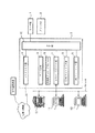
図2は、図1に示す本実施の形態例の画像処理装置の一例を示す断面図である。図2において、100は複写装置本体、180は循環式自動原稿送り装置(RDF)である。図1におけるリーダ部1は、図2の101〜109、プリンタ部2は、図2の110〜163に対応する。
【0032】
図2において、101は原稿載置台としてのプラテンガラス、102はスキャナであり、スキャナ102は原稿照明ランプ103、走査ミラー104等で構成されている。不図示のモータによりスキャナが所定方向に往復走査されて原稿の反射光を走査ミラー104〜106を介してレンズ108を透過してCCDセンサ109に結像する。
【0033】
107はレーザ、ポリゴンスキャナ等で構成された露光制御部であり、露光制御部107はイメージセンサ部109で電気信号に変換され、後述する所定の画像処理が行われた画像信号に基づいて変調されたレーザ光129を感光体ドラム110に照射する。感光体ドラム110の回りには、1次帯電器112、現像器121、転写帯電器118、クリーニング装置116、前露光ランプ114が装備されている。
【0034】
画像形成部126において、感光ドラム110は不図示のモータにより図に示す矢印の方向に回転しており、1次帯電器112により所望の電位に帯電された後、露光制御部120からのレーザ光129が照射され、静電潜像が形成される。感光体ドラム110上に形成された静電潜像は、現像器121により現像されて、トナー像として可視化される。
【0035】
一方、上段カセット131あるいは下段カセット132からピックアップローラ133,134により給紙された転写紙は、給紙ローラ135,136により本体100の画像形成部内に送られ、レジストローラ137により転写ベルトに給送され、可視化されたトナー像が転写帯電器118により転写紙に転写される。
【0036】
転写後の感光体ドラムは、クリーナー装置116により残留トナーが清掃され、前露光ランプ114により残留電荷が消去される。また、転写後の転写紙は、転写ベルト130から分離され、定着前帯電器139,140によりトナー像が再帯電され、定着器141に送られ加圧、加熱により定着され、排出ローラ142により本体100のソートに排出される。
【0037】
119はレジストローラから送られた転写紙を転写ベルト130に吸着される吸着帯電器であり、138は転写ベルト130の回転に用いられると同時に、吸着帯電器119と対になって、転写ベルト130に転写紙を吸着帯電させる転写ベルトローラである。
【0038】
本体100には、例えば4000枚の転写紙を収納し得るデッキ150が装備されている。デッキ150のリフタ151は、給紙ローラ152に転写紙が常に当接するように転写紙の量に応じて上昇する。また、100枚の転写紙を収容し得るマルチ手差し153が装備されている。
【0039】
更に、図2において、154は排紙フラッパであり、両面記録側ないし多重記録側と排紙側の経路を切り替える。排紙ローラ142から送り出された転写紙は、この排紙フラッパ154により両面記録側ないし多重記録側に切り替えられる。
【0040】
また、157は両面記録と多重記録の経路を切り替える多重フラッパであり、これを左方向に倒すことにより、転写紙を反転パス155に返さず、直接下搬送パス158に導く。159は経路160を通じて転写紙を感光体ドラム126側に給紙する給紙ローラである。161は排紙フラッパ154の近傍に配置させて、この排紙フラッパ154により排出側に切り替えられた転写紙を機外に排出する排出ローラである。
【0041】
両面記録(両面複写)時には、排紙フラッパ154を上方に上げるとともに、多重フラッパ157を右に倒し、複写済みの転写紙を反転パス155に送って収納したあと、多重フラッパ157を左に倒し、反転パス155に収納した転写紙を搬送パス158に送る。このとき、転写紙を反転パス155で反転させることにより転写紙を裏返した状態で搬送パス158に送ることができる。そして、裏返した状態で再給紙トレイ156に格納する。
【0042】
また多重記録(多重複写)時には、排紙フラッパ154を上方に上げて、多重フラッパ157を左に倒し、複写済みの転写紙を搬送パス158に送ってのち再給紙トレイ156に格納する。再給紙トレイ156に格納されている転写紙が、下から1枚ずつ給紙ローラ159により経路160を介して本体のレジストローラ137に導かれる。
【0043】
本体100から転写紙を反転して排出する時には、排紙フラッパ154を上方へ上げ、フラッパ157を右方向へ倒し、複写済みの転写紙を反転パス155側へ搬送し、転写紙の後端が第1の送りローラ162を通過した後に、反転ローラ163によって第2の送りローラ162a側へ搬送し、排出ローラ161によって、転写紙を裏返して機外へ排出される。
【0044】
図3は図1に示すリーダ部1の詳細構成を示すブロック図である。図3において、CCD209から出力された画像データはA/D・SH部210でアナログ/デジタル変換が行われるとともに、シェーディング補正が行われる。A/D・SH部210によって処理された画像データは画像処理部211を介してプリンタ部2へ転送されるとともに、インタフェイス部213を介して画像入出力制御部3のコア部10へ転送される。
【0045】
CPU214は操作部500で設定された設定内容に応じて画像処理部211及びインタフェイス213を制御する。例えば、操作部500でトリミング処理を行って複写を行なう複写モードが設定されている場合は、画像処理部211でトリミング処理を行なわせてプリンタ部2へ転送させる。
【0046】
また、操作部500でファクシミリ送信モードが設定されている場合は、インタフェイス213から画像データと設定されたモードに応じた制御コマンドをコア部10へ転送させる。このようなCPU214の制御プログラムはメモリ216に記憶されており、CPU214はメモリ216を参照しながら制御を行なう。また、メモリ216はCPU214の作業領域としても使われる。
【0047】
更に、メモリ216は、本実施の形態例の複写機ユーザの部門番号とパスワードを登録するためにも使用される。
【0048】
図4は図1に示すコア部10の詳細構成を示すブロック図である。図4において、リーダ部1からの画像データはデータ処理部121へ転送されるとともに、リーダ部1からの制御コマンドはCPU323へ転送される。
【0049】
データ処理部321は、主に画像の回転処理や変倍処理などの画像処理を行なう。リーダ部1からデータ処理部321へ転送された画像データは、リーダ部1から転送された制御コマンドに応じて、インタフェイス320を介してファクシミリ部4、ファイル部5、ネットワークインターフェイス部7へ転送される。
【0050】
また、ネットワークインターフェイス部7を介して入力された画像を表すコードデータは、データ処理部321に転送され、そのPDLがLIPSであるのかあるいはポストスクリプトであるのかが判定される。そして、しかるべきフォーマッタ部8ないし9へ転送されて画像データに展開される。この画像データはデータ処理部321に転送された後、ファクシミリ部4やプリンタ部2へ転送される。
【0051】
ファクシミリ部4からの画像データは、データ処理部321へ転送された後、プリンタ部2やファイル部5、ネットワークインターフェイス部7へ転送される。また、ファイル部5からの画像データは、データ処理部121へ転送された後、プリンタ部2やファクシミリ部4、ネットワークインターフェイス部7へ転送される。
【0052】
CPU323は、メモリ324に記憶されている制御プログラム、及びリーダ部1から転送された制御コマンドに従って上述したような各種の制御を行なう。また、メモリ324はCPU323の作業領域としても使われる。
【0053】
ネットワークインターフェイス部7にはMIB(Management Information Base)と呼ばれるデータベースが構築されており、SNMPプロトコルを介してネットワーク上のコンピュータと通信し、プリンタの管理が可能になっている。
【0054】
更に、本実施の形態例における詳細を後述する他のデジタル複写機に登録されているユーザIDを受信する場合、例えば、TCP/IPプロトコルで、他のデジタル複写機と通信し、他のデジタル複写機の種類や、ユーザIDが登録されているかの情報を受け取り、それに基づいて、他の複写機に登録されているユーザIDを受信し、自分のデジタル複写機のユーザIDとして、リーダ部1の、メモリ216に登録する。
【0055】
このように、コア部10を中心に、原稿画像の読み取り、画像のプリント、画像の送受信、画像の保存、コンピュータからのデータの入出力などの機能を複合させた処理を行なうことが可能である。
【0056】
図5は本実施の形態例におけるリーダ部1の表示部に表示される基本画面の一例であるコピーモードの画面の表示例を示す図である。図5の外側の枠で囲った部分が表示部である。この表示部の右側には後述する5つのキー523〜528が設けられている。なお、この表示部はタッチパネルとなっており、それぞれ表示される機能の枠内を指などで触れることにより、その表示されている機能が実行される。
【0057】
ガイドキー523は、あるキーの機能がわからないとき押すキーであり、ガイドキー523を押してから説明をしてほしいキーにタッチするとそのキーの説明が表示される。コピーモードキー524は、複写動作を行なう場合に押すキーである。そしてこのコピーモードキー524が押されたときに、図5に示すコピーモードの画面を表示する。
【0058】
ファックスキー525は、装置をファクシミリ装置として使用するときに押すキーであり、ファイルキー526は、ファイルデータを出力したいときに押すキーである。プリンタキー427は、プリントの濃度を変更したり、リモートのホストからのPDL画像のプリント出力結果を参照したい場合に押すキーである。IDキー528は後述するパスワード入力画面に移行させるキーである。
【0059】
表示部500において、501は拡張機能キーであり、このキーを押すことによって両面複写、多重複写、移動、とじ代の設定、枠消しの設定等のモードに入る。502は画像モードキーであり、このキーを押すことによって複写画像に対して網掛け、影付け、トリミング、マスキングを行なうための設定モードに入る。
【0060】
503はユーザモードキーであり、このキーであり、このキーを押すことによって、モードメモリの登録、標準モード画面の設定が行なえる。504は応用ズームキーであり、このキーを押すことによって、原稿のX方向、Y方向を独立に変倍するモード、原稿サイズと複写サイズから変倍率を計算するズームプログラムのモードに入る。
【0061】
M1キー505、M2キー506、M3キー507は、それぞれに登録されたモードメモリを呼び出す際に押すキーである。オプションキー509は、フィルムから直接複写するためのフィルムプロジェクタ等のオプション機能の設定を行なうキーである。
【0062】
ソータキー510は、メカソータを使用するか、電子ソータを使用するかの設定、及びソータのソート、グループ等のモード設定を行なうキーである。原稿混載キー511は、原稿フィーダにA4サイズとA3サイズ、またはB5サイズとB4サイズの原稿を一緒にセットする際に押すキーである。
【0063】
等倍キー512は、複写変倍率を100%にする際に押すキーである。縮小キー514、拡大キー515は、定型の縮小、拡大を行なう際に押すキーである。用紙選択キー513は、複写用紙の選択を行なう際に押すキーである。濃度キー518,520は、キー518を押す毎に濃く複写され、キー520を押す毎に薄く複写される。濃度表示517は、濃度キーを押すと表示が左右に変化する。
【0064】
AEキー519は、新聞のように地肌の濃い原稿を自動濃度調整複写するときに押すキーである。HiFiキー521は、写真原稿のように中間調の濃度が多い原稿の複写の際に押すキーである。文字強調キー522は、文字原稿の複写で文字を際だたせたい場合に押すキーである。
【0065】
530は、プリンタ選択キーであり、本実施の形態例に特有の詳細を後述する、リモートコピー処理、重連コピー処理を行なう場合の受信側複写機を選択する際に押すキーである。このプリンタ選択キー530を押した場合には、後述する図11に示す画面に移行する。
【0066】
図6は、本実施の形態例における操作部500におけるユーザID(部門番号とパスワード)を入力するパスワード入力画面の例を示す図である。
【0067】
ユーザが本実施の形態例の画像処理装置を使おうとするときには、自分の部門番号とパスワードを入力する。そして、あらかじめ画像処理装置のメモリ216に登録されている部門番号とパスワードの組み合わせと一致したらその後の操作を可能としており、その後に図5に示す基本操作画面に移行し、例えばコピー動作が可能となる。
【0068】
メモリ216に登録されている部門番号とパスワードの組み合わせと一致しない場合は、パスワード不一致であることを操作部に表示し、コピー動作等のその後の操作を許容しない。
【0069】
図6において、601は部門IDキーであり、部門IDキー601を押したあと、図示しないテンキーで、自分の部門番号、例えば図6の場合、「1234」を入力する。602は暗証番号キーであり、上記のように部門番号を入力したら、このキーを押し、図示しないテンキーで、自分の部門番号に対応するパスワード、例えば図6の場合、「6789」を入力する。
【0070】
603はOKキーであり、入力した部門番号とパスワードを確認し、この入力した番号で良い場合であらかじめ画像処理装置のメモリ216に登録されている部門番号とパスワードの組み合わせと照合する場合に押すキーである。
【0071】
このOKキー603を押し、あらかじめ画像処理装置に登録されている部門番号とパスワードの組み合わせのいずれかと一致した場合には上述した図5の基本画面に移行する。
【0072】
そして、例えばコピー動作が終了したら、ユーザは、IDキー528を押して図6のパスワード入力画面に移行させる。もしくは、画像形成動作が終了後、1分間、画像処理装置の操作部のキーが押されなかったら、ユーザが使い終わったと判断し、自動的に図6に示すパスワード入力画面に移行する。
【0073】
部門番号とパスワードの組み合わせが、あらかじめ画像処理装置に登録されている部門番号とパスワードの組み合わせのいずれかと一致しない場合は、パスワード不一致であることを操作部に表示し、コピー動作は可能としない。入力した部門番号とパスワードの入力を間違えた場合、図示しないクリアキーで、入力したデータ、例えば図6の場合、部門番号「1234」、パスワード「6789」の入力を無効にする。
【0074】
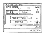
図7は、操作部500における部門別ID管理画面を説明するための図であり、部門番号とパスワードの登録、あるいは、部門番号に対するコピー(プリント)枚数カウンタを参照、クリアするための画面である。
【0075】
図示しない管理者キーを押したあと、図示しないテンキーにより、管理者用パスワードを入力し、あらかじめ画像処理装置のメモリ216に登録されている管理者用パスワードと一致した場合、図示しない管理者画面を表示し、そこで「部門別ID管理キー」を押したら、図7の画面に移行する。
【0076】
611は部門別ID管理有効キーであり、これを押してキーを反転させることにより、部門別ID管理を有効にする。つまり、図6の画面を表示させ、ユーザに部門番号とパスワードを入力させ、あらかじめ画像処理装置に登録されている部門番号とパスワードと一致したら図5の基本画面を表示して画像処理装置の使用を有効にし、一致しなかったら無効にするという制御を行なうようにする。
【0077】
612は部門別ID管理無効キーであり、これを押してキーを反転させることにより、ユーザに対して、部門番号とパスワードの入力はさせず、図6の画面は表示せずに、図5の基本画面を表示して、ユーザの認証なしに、画像処理装置を使用できるようにする。
【0078】
613は暗証番号登録キーであり、これを押すことにより、画像処理装置のメモリ216に、画像処理装置の使用を許可する部門番号とパスワードをすべて登録する。ただし、後述する、本実施の形態例の制御方法によると、操作部から、管理する部門数分の部門番号とパスワードを入力する作業は、省略される。
【0079】
614はカウント管理キーであり、これを押すことにより、部門番号に対するコピー、またはプリントした枚数の一覧が表示される。
【0080】
615は取り消しキーであり、これを押すことにより図7の画面で押したキーの設定を無効にし、部門別管理をしている状態なら図6の画面に、部門別管理をしていない状態なら図5の画面に移行する。
【0081】
616はOKキーであり、これを押すことにより図7の画面で押したキーの設定を有効にする。611を押した後、616のOKキーを押せば部門別管理が有効となり、図6の画面に移行し、ユーザに部門番号とパスワードの入力を促す。
【0082】
部門別ID管理無効キー612を押した後にOKキー616を押せば、部門別管理が無効となり、図5の基本画面に移行し、ユーザの認証なしに、ユーザは画像処理装置の使用ができるようになる。暗証番号登録キー613を押したあと、OKキー616を押せば、上述する図8の画面に移行する。また、カウント管理キー614を押したあとにOKキー616を押せば、後述する図9の画面に移行する。
【0083】
図8は本実施の形態例における部門番号、パスワード設定画面を説明するための図である。図8において、621は部門番号設定欄であり、登録する部門番号の欄をタッチして反転させ、部門番号、例えば「1234」を図示しないテンキーで入力する。622はパスワード設定欄であり、部門番号に対応するパスワードの欄をタッチして反転させ、パスワード、例えば「4321」を、図示しないテンキーで入力する。
【0084】
図8の例では、部門番号「1234」に対して、パスワード欄をタッチし、反転させ、図示しないテンキーで、「4321」を入力した様子を示している。
【0085】
623は下スクロールキーであり、部門番号とパスワード一覧の次の画面を表示するために押す。624は上スクロールキーであり、部門番号とパスワード一覧の前の画面を表示するために押す。627は取り消しキーであり、これを押すことで、入力した部門番号とパスワードのデータを無効にし、図7の画面に戻る。
【0086】
625はOKキーであり、設定した部門番号とパスワードの入力を有効にし、メモリ216に、新たに入力された部門番号とパスワードすべてを書き込んで登録する。なお、OKキーを押すまでに入力された部門番号とパスワードの幅は、メモリ216の一時バッファエリアに格納し、627の取り消しキーを押された場合はこのエリアをクリアし、OKキーを押された場合はこのエリアから部門番号とパスワードを、メモリ216の部門番号、パスワード登録エリアに移す。
【0087】
なお、後述する本実施の形態例の制御手段によれば、例えば、新たな画像処理装置の設置時、操作部による、これらの部門番号とパスワードの入力作業を省略することができる。つまり、他の画像処理装置に以前登録されている、部門番号とパスワードの一覧データをネットワークを通じて、自分の画像処理装置のメモリ216の部門番号、パスワード登録エリアにコピーする。
【0088】
もちろん、このコピーにより、部門番号、パスワードの一覧が登録された後に、部門番号、パスワードの追加登録が必要になった場合には、図8の画面により、登録作業を行っても良いことになる。
【0089】
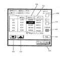
図9は、本実施の形態例における部門別カウント/上限設定画面を説明するための図である。図9において、630は部門番号表示欄であり、画像処理装置を使用している部門番号を表示している。631はカウント表示欄であり、部門番号のユーザが何枚コピーあるいは、プリントしたかの数値(プリント量)を示す。
【0090】
ここで、カウント表示欄に表示されるカウント値は、プリントに要した紙の枚数でもよいし、また、両面プリントやNupプリントなどに対応すべく、プリントされた画像の数(例えば、両面プリントでは、1枚の紙に対しカウント値は2)でもよい。
【0091】
例えば、図9の場合、部門番号1234の部門は、123枚コピーまたはプリントしたことを示している。634は下スクロールキーであり、部門番号とカウンタ一覧の次の画面を表示するために押す。635は上スクロールキーであり、部門番号とカウンタ一覧の前の画面を表示するために押す。
【0092】
636はカウントオールクリアキーであり、管理者が部門番号とカウンタ一覧のデータを書き移す。またはプリントした後、すべての部門のカウンタをリセットする場合に押す。637はカウントプリントキーであり、部門番号とカウンタの一覧を、画像処理装置からプリントアウトする場合に押す。632はOKキーであり、これを押すことで、図7の画面に戻る。
【0093】
638は上限カウンタ表示欄であり、各部門番号に対応するユーザに対してプリントを許可する枚数の設定状況を表示する欄である。例えば図9の例では、部門ID1234の部門に対しては2000枚までプリントを許可し、プリントジョブ終了後にカウント欄630のカウンタ値が2000枚を超えている場合には以降のプリントを禁止することを示している。また、上限カウンタ表示欄638の上限カウントデータ及びカウント欄630のカウントデータは、部門IDやパスワードを保持しているメモリ216内に保持される。
【0094】
639は上限有効キーであり、この上限有効キー639を押すことにより、上限カウンタ表示欄638で設定された上限カウンタによるプリント制御が有効となる。例えば、部門ID1234に対して、プリント枚数の制限を2000枚とすることができる。有効な状態の場合には、上限有効キー639は反転表示され、有効状態であると容易に判別可能な表示となっている。
【0095】
上限カウンタによるプリント制御が無効である場合には、上限有効キー639は通常表示となり、上限カウント欄の上限枚数による制御は無効となる。例えば、部門ID1234に対して、上限枚数が2000と設定されている状態で、プリント枚数が2000枚を超えても無制限にプリントすることが可能となる。
【0096】
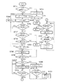
図10は本実施の形態例で採用されている画像処理システムの概略ネットワーク構成を説明するための図である。図10の例は、リモートコピー及び重連コピーが可能なネットワークシステムの例を示している。
【0097】
図10において、13,20,21はネットワークを介して互いに接続可能なデジタル複写機であり、お互いにネットワークを通じて、例えばTCP/IPなどのプロトコルで、部門IDや、画像データのやり取りを行なう。例えば、リモートコピー、重連コピーの送信側としてデジタル複写機13、受信側としてデジタル複写機20としてもよい。
【0098】
その場合、デジタル複写機13が備えるスキャナで読み取った原稿画像データを、ネットワークを介して、デジタル複写機20に送信し、デジタル複写機20のプリンタでプリントし、リモートコピーを行なう。または、このとき、デジタル複写機13のプリンタからも同時に原稿画像データをプリントすることで、重連コピーを行なうことができる。
【0099】
例えば、デジタル複写機13に5部をプリントし、デジタル複写機20にも5部プリントをさせるように制御すれば、1台の複写機で10部プリントするよりも、2倍近い速さで同じ10部のプリントを得ることができる。更に、受信側のデジタル複写機として、複写機21を加え、送信側であるデジタル複写機13のプリンタで4部プリント、受信側であるデジタル複写機20で3部プリント、受信側であるデジタル複写機21で3部プリントするように制御すれば、更に速いパフォーマンスで、合計10部のプリントを得ることができる。
【0100】
図11は、図5に示す基本画面においてプリンタ選択キー530を押した場合に表示する操作部の様子を示す図である。この画面からリモートコピーまたは重連のコピーの受信側の複写機を選択することができる。
【0101】
図11において、700は複写機名称欄であり、ネットワークに接続されている他の受信側の複写機の名称を表示している。701は状況表示欄であり、他の受信側の複写機と通信ができているかどうかを示している。通信が正常ならOK、通信異常か、受信側の複写機の電源がOFFなら、「NG」と表示している。
【0102】
702はIPアドレス欄であり、各受信側の複写機のIPアドレスを表示している。例えば、総務GP215というデジタル複写機とは現在通信可能であり、GP215のデジタル複写機のIPアドレスが、123.456.789.000であることを示している。
【0103】
703は、IPアドレス指定欄であり、この部分をタッチした後、図示しないテンキーによるIPアドレスを入力して検索キー709を押すことにより、新規の受信側の複写機をサーチすることができる。サーチが成功したら名称欄704に検索された受信側の複写機の名称が表示され、状況欄705が「OK」となる。
【0104】
一定時間検索しても見つからなかったときは、例えば「複写機が見つかりません」等のメッセージを図11の上部に表示する。706,707は、それぞれ下スクロールキー、上スクロールキーであり、受信側の複写機の一覧が一画面で表示しきれない場合、画面をスクロールする。
【0105】
708は重連キーであり、指定した受信側複写機と重連コピーを行なう場合に押下入力する。このキーが入力されるとキーが反転し(黒くなって)、重連コピーを行なう動作モードとなり、もう一度押したらキーが白くなり重連コピーでなく、リモートコピーを行なうことになる。また、複写機を指定する場合は、指定したい複写機の名称欄をタッチし、表示を反転させる。図11の場合、総務GP215が指定された状態となる。
【0106】
710はOKキーであり、受信側複写機として指定した複写機の名称欄を押して、リモートコピー、あるいは重連コピーを行ないたい場合に入力し、このキーが入力されると図5に示す基本画面に戻る。あるいは、何も指定せずにOKキー710を押して図5の基本画面に戻ってもよい。
【0107】
受信側複写機を指定して図5の基本表示に戻った場合、プリンタ選択キーが反転した状態となる。受信側複写機を指定せず図5の基本画面表示に戻った場合にはプリンタ選択キー530は反転しない。
【0108】
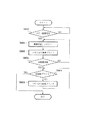
次に、以上の構成を備える本実施の形態例におけるリモートコピー、あるいは重連コピーを行なう場合の送信側複写機13の制御を説明する。図12は本実施の形態例におけるリモートコピー、あるいは重連コピーを行なう場合の送信側複写機13の制御を説明するためのフローチャートである。本実施の形態例ではコピーを行なうに先立って送信側複写機のスキャナにコピーするべき原稿をあらかじめセットする。
【0109】
リモートコピー、あるいは重連コピーを行なう場合の送信側複写機13ではまずステップS501で、図5の基本操作画面において、コピーモード、例えば、片面コピー10部などの設定を行なう。続いてステップS502において、図5の基本画面でプリンタ選択キー530を押し、図11に示すプリンタ選択表示画面を参照して受信側の複写機20の選択を行なう。例えば、総務GP215を選んでOKキー710を押す等の選択を行なう。
【0110】
次にステップS503で、指定されたコピー処理が可能かどうかを判断する。例えば、両面コピーを行なうのに受信側の受信側の複写機に両面ユニットが無い場合など指定されたコピー処理が出来ない場合でないか否かを判断する。ステップS503の判断で指定されたコピーが行なえない場合はステップS504に進み、例えば図5の画面の上部に警告メッセージを表示する等の警告表示を行なう。このステップS503の判断においては、受信側複写機とネットワークを介して通信を行い、受信側複写機の両面ユニットの装着状況等、受信側複写機の情報を取得して上記判断を行なっている。警告メッセージを表示した後はステップS501に戻る。
【0111】
一方、ステップS503でコピーが可能であればステップS505に進み、スキャナにセットされた原稿画像をスキャンして原稿画像を読み込み、読み込んだ画像データをメモリ216に蓄積する。そしてステップS506でセットされた全原稿をスキャンして画像データをすべてメモリ216に蓄積し終わったか否かを判断する。スキャンするべき原稿がまだある場合にはステップS505に戻る。
【0112】
一方、スキャナにセットされた原稿画像をすべてスキャンして原稿画像を読み込み、読み込んだ画像データをメモリ216に蓄積し終わった場合にはステップS506よりステップS507に進み、リモートコピーが指定されているかあるいは重連コピーが指定されているかを判断する。ステップS507で重連コピーが指定されていない場合にはステップS509に進む。
【0113】
一方、ステップS507で重連コピーが指定されている場合にはステップS508に進み、メモリ216に蓄積されている画像データを読み出し、自複写機のプリンタよりプリントする様に制御する。そしてステップS509に進む。
【0114】
ステップS509では、メモリ216から、先に蓄積した原稿画像データを読み出し、CPU214、画像処理部211、I/F213、I/F322、データ処理部321、I/F320を介して、ネットワークインターフェイス部7に転送する。そして、ネットワークを通じて、受信側複写機20へ、原稿画像データを転送する。続いてステップS510で全原稿画像データを読み出し、転送終了したか否かを判断する。全原稿画像データを読み出し、転送終了していなければステップS507に戻る。
【0115】
一方、ステップS510で全原稿画像データを読み出し、転送終了している場合にはステップS511に進み、重連コピーで必要部数分を送信側複写機でプリント終了したか否かを判断する。必要部数分を送信側複写機でプリントしていない場合にはステップS512に進み、1部プリントするように制御してステップS511に進む。
【0116】
一方、ステップS511で必要部数分のプリントが終了している場合には当該処理を終了する。
【0117】
次に、以上のような制御に従った送信側複写機よりの通信制御に対応したプリント制御を行なう受信側複写機のリモートコピーまたは重連コピー制御を図13を参照して説明する。図13は本実施の形態例におけるリモートコピー、あるいは重連コピーを行なう場合の受信側複写機20の制御を説明するためのフローチャートである。
【0118】
受信側複写機20は、まずステップS601において、送信側複写機13からのコピー情報が送られてきたか否か(コピー情報を受信したか否か)を判断する。コピー情報が受信されない場合には受信されるのを監視する。
【0119】
ステップS601において、送信側複写機13から図12のステップS503の処理でコピー情報データが送信されて来た場合にはステップS602に進み、送られてくる送信側複写機13よりのコピー情報データを、受信側複写機20のネットワークインターフェイス部7、I/F320、データ処理部321、I/F322、I/F213、画像処理部211を介して受け取る。このコピー情報を解析し、例えば、両面コピーで5部プリントする指示であること等送信複写機13よりの具体的な指示内容を認識する。このとき、例えば、両面コピーの指示で自分の複写機に両面ユニットが無い場合などは、ネットワークを介して警告情報を、同じルートで逆方向に、送信側複写機13に返信する。
【0120】
重連コピー制御の場合等ではその後送信側複写機13からの原稿画像データを受け取る必要があるため、ステップS602において送信側複写機13からの原稿画像データを同じルートで受信し、メモリ216に格納する。原稿画像データの受信及びメモリ216への格納が終了するとステップS603に進み、メモリ216に格納された原稿画像データを読み出し、画像処理部211を介してプリンタ部2に転送してプリントアウトさせる。
【0121】
次にステップS604で全原稿画像データを受信したかを判断し、全原稿画像データを受信していない場合にはステップS602に戻り、次の原稿受信を行なう。
【0122】
一方、ステップS604において、全原稿画像データを受信し終わった場合にはステップS605に進み、コピー情報データで指示された全部数分のプリントが終わったかを判断する。コピー情報データで指示された全部数分のプリントがまだ終了していない場合にはステップS606に進み、ステップS602でメモリ216に格納した原稿画像データを読み出し、画像処理部211を介してプリンタ部2に転送して1部プリントアウトさせる。そしてステップS605に戻る。
【0123】
一方、ステップS605でコピー情報データで指示された全部数分のプリントが終了した判断した場合には当該処理を終了する。
【0124】
本実施の形態例においては、図12、図13の処理とは別に、ユーザIDを用いて部門管理を行なうことが可能であり、ユーザIDを用いて部門管理を行なう場合には以下の図14、図15に示す制御を行なう。
【0125】
次に、図14を参照して本実施の形態例における部門管理を行なう場合と部門管理を行なわない場合における送信側の複写機13のリモートコピー/重連コピー制御を説明する。図14は本実施の形態例における部門管理を行なう場合と部門管理を行なわない場合における送信側の複写機13のリモートコピー/重連コピー制御を説明するためのフローチャートである。
【0126】
ユーザIDを用いて部門管理を行なう場合には、まずステップS713で部門管理を行なうか否かを判定する。部門管理を行なわない場合にはステップS701に進む。部門管理ありとは、図7に示す部門別ID管理画面で、部門管理するを選択し、OKにした状態である。部門管理なしとは、同画面で、部門管理しないを選択し、OKにした状態である。
【0127】
一方、ステップS713で部門管理ありと指定されていると判断した場合にはステップS714に進み、図6に示す画面を表示し、部門IDと暗証番号を入力させ、OKを押させて、あらかじめメモリ216に登録されている部門IDと暗証番号と認証する。そして、ステップS715で認証した場合にはステップS701の処理の意向する。
【0128】
一方、ステップS715で入力された部門IDと暗証番号が、あらかじめメモリ216に登録されている部門IDと暗証番号と照合しない場合には処理を終了して装置に操作を中止させる。
【0129】
ステップS701では、図5に示す基本画面において、コピーモード設定を行なう。例えば、片面コピー10部などの設定を行なう。続いてステップS702において、図5の基本画面のプリンタ選択キー530を入力し、図11の画面で受信側の複写機20の選択を行い、例えば、総務GP215を選んでOKキー710を押す。
【0130】
次にステップS716で、受信側の複写機が部門管理ありの状態か否かの情報を受信側の複写機と通信することで取得して受信側の複写機が部門管理ありの状態か否かを判断する。受信側が部門管理なしの状態である場合にはステップS703に進む。
【0131】
一方、ステップS716で、受信側の複写機が部門管理ありの状態の場合にはステップS717に進み、送信側の複写機が部門管理ありの状態か否かを判定する。送信側の複写機が部門管理無しの状態の場合には、受信側へ部門ID、暗証番号を送信することができず、受信側の複写機で部門管理できない状態、つまり、受信側の複写機で部門管理ありの状態のときに、部門ID、暗証番号無しでプリントできないため、リモートコピー、重連コピーを実行することができない。このため当該処理を終了する。
【0132】
一方、ステップS717で送信側複写機が部門管理あり状態に設定されている場合にはステップS718に進み、先のステップS714で入力された部門ID、暗証番号と、受信側複写機側のメモリにあらかじめ登録されている部門ID、暗証番号をネットワーク通信を使って照合する。ステップS718で照合しなかったら、リモートコピー、重連コピーができないので当該処理を終了する。
【0133】
一方、ステップS718で先のステップS714で入力された部門ID、暗証番号と、受信側複写機側のメモリにあらかじめ登録されている部門ID、暗証番号が照合した場合にはステップS703に進む。
【0134】
ステップS703では、コピー可能かどうかを判断する。例えば、両面コピーを行なうのに、受信側の複写機に両面ユニットが無い場合など、コピーが行なえない場合はステップS704に進み、図5に示す基本画面の上部に警告メッセージを表示してステップS701に戻る。ステップS703においては、受信側複写機とネットワークを介して通信を行い、受信側複写機の両面ユニットの装着状態等、受信側複写機の情報を取得してコピー可能かどうかを判断する。
【0135】
一方、ステップS703でコピー可能であった場合にはステップS705に進み、スキャナにセットされている原稿画像をスキャンして原稿画像を読み取り、読み取った画像データをメモリ216に蓄積する。続いてステップS706で全原稿をスキャンして画像データをすべてメモリ216に蓄積し終わったか否かを判断する。すべての原稿をスキャンして画像データをすべてメモリ216に蓄積し終わっていない場合にはステップS705に戻る。
【0136】
一方、ステップS706において、原稿をスキャンして画像データをすべてメモリ216に蓄積し終わっ終わった場合にはステップS707に進み、リモートコピーか、重連コピーかを判断する。重連コピーの場合には重連キー708が押されている。ステップS707で重連コピーの場合にはステップS708に進み、メモリ216に蓄積されている画像データを読み出してプリントアウトする。そして続くステップS719において、送信側複写機が部門管理ありか否かを判定する。送信側複写機が部門管理ありでない場合にはステップS710に進む。
【0137】
一方、ステップS719で送信側複写機が部門管理ありの場合にはステップS720に進み、使用中の部門IDに対する部門カウンタをプリント枚数に応じてカウントアップしてステップS710に進む。
【0138】
一方、ステップS707で重連コピーでない場合にはステップS709に進み、メモリ216かスキャンした原稿画像データを読み出し、CPU214、画像処理部211、I/F213、I/F322、データ処理部321、I/F320を介して、ネットワークインターフェイス部7に転送する。そして、ネットワークを通じて、受信側複写機20へ、原稿画像データを転送する。続いてステップS710で全原稿画像データを読み出し、転送終了したかを判断する。全原稿画像データの読み出し転送が終了していなければステップS707に戻る。
【0139】
一方、ステップS710で全原稿画像データの読み出し転送が終了したらステップS711に進み、重連コピーで必要部数分、送信側複写機でプリント終了したか否かを判断する。送信側複写機でプリント終了している場合には当該処理を終了する。
【0140】
一方、ステップS711で送信側複写機でプリント終了していな場合にはステップS712に進み、更に1部プリントアウトする。そして続くステップS721で送信側部門管理ありか否かを判断する。送信側部門管理無しの場合にはステップS711に戻る。
【0141】
一方、ステップS721で送信側部門管理ありの場合にはステップS722に進み、使用中の部門IDに対する部門カウンタをカウントアップしてステップS711に戻る。
【0142】
そして必要部数分プリントしたらステップS711より当該処理を終了する。
【0143】
次に図15を参照して本実施の形態例における部門管理を行なう場合と部門管理を行なわない場合における受信側の複写機20のリモートコピー/重連コピー制御を説明する。図15は本実施の形態例における部門管理を行なう場合と部門管理を行なわない場合における受信側の複写機20のリモートコピー/重連コピー制御を説明するためのフローチャートである。
【0144】
受信側複写機20は、まずステップS801において、送信側複写機13からのコピー情報が送られてきたか否か(コピー情報を受信したか否か)を判断する。コピー情報が受信されない場合には受信されるのを監視する。ステップS801において、送信側複写機13から図14のステップS716の処理でコピー情報データが送信されて来た場合にはステップS802に進み、送られてくる送信側複写機13よりのコピー情報データを、受信側複写機20のネットワークインターフェイス部7、I/F320、データ処理部321、I/F322、I/F213、画像処理部211を介して受け取る。このコピー情報を解析し、例えば、両面コピーで5部プリントする指示であること等送信複写機13よりの具体的な指示内容を認識する。このとき、例えば、自分の複写機に両面ユニットが無いとしたら、警告情報を、同じルートで逆方向に、送信側複写機13へネットワークで返信する。また、送信側複写機から、受信側複写機が部門管理ありの状態か無しの状態かの問い合わせがあった場合、結果を返信する。更に、送信側複写機から、受信側複写機に対して、送信側複写機の操作部から入力された部門IDと暗証番号をネットワーク通信により受け取り、受信側複写機のメモリ216にあらかじめ登録されている部門IDと暗証番号に一致しているかの問い合わせ(照合)に対しても結果を返信する。
【0145】
重連コピー制御の場合等ではその後送信側複写機13からの原稿画像データを受け取る必要があるため、ステップS802において送信側複写機13からの原稿画像データを同じルートで受信し、メモリ216に格納する。原稿画像データの受信及びメモリ216への格納が終了するとステップS803に進み、メモリ216に格納された原稿画像データを読み出し、画像処理部211を介してプリンタ部2に転送してプリントアウトさせる。
【0146】
続いてステップS807で受信側複写機が部門管理ありか否かを判定する。受信側複写機が部門管理無しの場合にはステップS804に進む。
【0147】
一方、ステップS807で受信側複写機が部門管理ありの場合にはステップS808に進み、送信側複写機から照合時に送られてきた部門IDに対する、受信側複写機のメモリ216にある部門カウンタをカウントアップする。そしてステップS804に進む。
【0148】
ステップS804では、全原稿画像データを受信したかを判断する。全原稿画像データを受信していない場合にはステップS802に戻り、次の原稿受信を行なう。
【0149】
一方、ステップS804において、全原稿画像データを受信し終わった場合にはステップS805に進み、コピー情報データで指示された全部数分のプリントが終わったかを判断する。コピー情報データで指示された全部数分のプリントがまだ終了していない場合にはステップS806に進み、ステップS802でメモリ216に格納した原稿画像データを読み出し、画像処理部211を介してプリンタ部2に転送して1部プリントアウトさせる。続いてステップS809で受信側複写機が部門管理ありか否かを判定する。受信側複写機が部門管理無しの場合にはステップS805に戻る。
【0150】
一方、ステップS809で受信側複写機が部門管理ありの場合にはステップS810に進み、送信側複写機から照合時に送られてきた部門IDに対する、受信側複写機のメモリ216にある部門カウンタをカウントアップする。そしてステップS805に戻る。
【0151】
一方、ステップS805でコピー情報データで指示された全部数分のプリントが終了した判断した場合には当該処理を終了する。
【0152】
以上の様に制御することにより、複数の画像処理装置、例えばデジタル複写機等を同時に使ってコピー等の画像処理する場合でも、それぞれのデジタル複写機に対して、それぞれ使用したユーザID毎に、確実に排紙枚数をカウントし、枚数管理が実現する。
【0153】
以上説明したように本実施の形態例によれば、送信側の複写機でユーザIDが登録されており、受信側の複写機で同様にユーザIDが登録されている状態で、リモートコピー、あるいは重連コピーを行なう場合、送信側の複写機の操作部からユーザIDを入力させ、送信側に登録されているユーザIDと認証して一致し、かつ、ネットワークを通じて、受信側に登録されているユーザIDと認証し、一致したら、リモートコピー、あるいは重連コピーを行なうようにしている。
【0154】
このため、リモートコピー、あるいは重連コピーを行なう場合にも、使用可能なユーザIDを制限して使用させることができるという効果がある。
【0155】
また、送信側複写機で部門管理されている場合で、かつ、受信側複写機で部門管理されている場合は、上記のような制御を行い、送信側複写機は部門管理されている場合で、受信側複写機で部門管理されていない場合は、送信側で複写機で入力されたユーザIDと、送信側複写機で登録されているユーザIDと認証し、一致したら、リモートコピー、重連コピーを可能として、排紙枚数は、送信側複写機でカウントすることで、使用可能なユーザIDを制限すると同時に、排紙枚数を管理したい送信側複写機では部門管理ができるという効果がある。
【0156】
送信側複写機で、部門管理されていない場合で、かつ、受信側複写機で部門管理されている場合は、送信側複写機では、ユーザID入力を促さないので、受信側複写機へ使用者のユーザIDを伝えることができない。このような場合は、リモートコピー、重連コピーを禁止し、受信側複写機の部門管理を正確なものにすることができるという効果がある。
【0157】
さらに、送信側複写機、受信側複写機ともに、部門管理されていない場合、送信側複写機ではユーザID入力を促さず、しかも、受信側複写機では、ユーザIDの使用者情報を必要としないので、リモートコピー、重連コピーを、誰もがいつでも使用することができるという効果がある。
【0158】
以上のように、送信側複写機、受信側複写機で、部門管理されている場合、されていない場合は、操作部のスイッチ(図5、図9、図11などの画面表示にしたがった制御指示入力)で容易に切り替えることができるので、用途に応じたリモートコピー、重連コピーの部門管理の方法が選択でき、利便性が向上するという効果がある。
【0159】
これにより、また、送信側デジタル複写機、受信がアデジタル複写機がそれぞれ、ユーザID毎のカウント枚数管理を行っている状態、行っていない状態のいずれかにおいても、その組み合わせにより、適切に枚数管理を実現することが出来る。
【0160】
【他の実施形態】
なお、以上の説明においては、プリント枚数により印刷量を管理していたが、これをプリント量を基準にしても良いことは勿論である。
【0161】
なお、本発明は、複数の機器(例えばホストコンピュータ、インタフェイス機器、リーダ、プリンタなど)から構成されるシステムに適用しても、一つの機器からなる装置(例えば、複写機、ファクシミリ装置など)に適用してもよい。
【0162】
また、本発明の目的は、前述した実施形態の機能を実現するソフトウェアのプログラムコードを記録した記憶媒体(または記録媒体)を、システムあるいは装置に供給し、そのシステムあるいは装置のコンピュータ(またはCPUやMPU)が記憶媒体に格納されたプログラムコードを読み出し実行することによっても、達成されることは言うまでもない。この場合、記憶媒体から読み出されたプログラムコード自体が前述した実施形態の機能を実現することになり、そのプログラムコードを記憶した記憶媒体は本発明を構成することになる。また、コンピュータが読み出したプログラムコードを実行することにより、前述した実施形態の機能が実現されるだけでなく、そのプログラムコードの指示に基づき、コンピュータ上で稼働しているオペレーティングシステム(OS)などが実際の処理の一部または全部を行い、その処理によって前述した実施形態の機能が実現される場合も含まれることは言うまでもない。
【0163】
更に、記憶媒体から読み出されたプログラムコードが、コンピュータに挿入された機能拡張カードやコンピュータに接続された機能拡張ユニットに備わるメモリに書き込まれた後、そのプログラムコードの指示に基づき、その機能拡張カードや機能拡張ユニットに備わるCPUなどが実際の処理の一部または全部を行い、その処理によって前述した実施形態の機能が実現される場合も含まれることは言うまでもない。
【0164】
本発明を上記記憶媒体に適用する場合、その記憶媒体には、例えば先に説明した各フローチャートに対応するプログラムコードが格納されることになる。
【0165】
【発明の効果】
以上説明したように本発明によれば、複数の画像処理装置等を同時に使って所定の画像処理、例えばコピー処理を行う場合でも、それぞれの画像処理毎にそれぞれ使用したユーザID毎に確実な画像処理の管理を実現することができる。また、ユーザによって1つの画像処理装置に対して入力されたユーザID及び暗証番号を使用して、当該画像処理装置の認証を行うとともに、画像処理を連携する他の画像処理装置に対して当該ユーザID及び暗証番号を送付して、他の画像処理装置における認証も実行することにより、ユーザにとっては両方の画像処理装置にユーザID及び暗証番号を入力する必要がなく、ユーザの作業を低減することができる。
【0166】
また、第1の画像処理装置、第2の画像処理装置がそれぞれ、ユーザID毎の画像処理量管理を行っている状態、行っていない状態のいずれかにおいても、その組み合わせにより、適切に画像処理管理を実現することが出来る。
【図面の簡単な説明】
【図1】本発明に係る一実施の形態例の画像処理装置の構成を示すブロック図である。
【図2】図1に示す本実施の形態例の画像処理装置の一例を示す断面図である。
【図3】図1に示すリーダ部の詳細構成を示すブロック図である。
【図4】図4は図1に示すコア部の詳細構成を示すブロック図である。
【図5】本実施の形態例におけるリーダ部の表示部に表示される基本画面の一例であるコピーモードの画面の表示例を示す図である。
【図6】本実施の形態例における操作部におけるユーザID(部門番号とパスワード)を入力するパスワード入力画面の例を示す図である。
【図7】本実施の形態例における操作部における部門別ID管理画面を説明するための図である。
【図8】本実施の形態例における部門番号、パスワード設定画面を説明するための図である。
【図9】本実施の形態例における部門別カウント/上限設定画面を説明するための図である。
【図10】本実施の形態例で採用されている画像処理システムの概略ネットワーク構成を説明するための図である。
【図11】本実施の形態例におけるプリンタ選択画面を説明するための図である。
【図12】本実施の形態例におけるリモートコピー、あるいは重連コピーを行なう場合の送信側複写機の制御を説明するためのフローチャートである。
【図13】本実施の形態例におけるリモートコピー、あるいは重連コピーを行なう場合の受信側複写機の制御を説明するためのフローチャートである。
【図14】本実施の形態例における部門管理を行なう場合と部門管理を行なわない場合における送信側の複写機のリモートコピー/重連コピー制御を説明するためのフローチャートである。
【図15】本実施の形態例における部門管理を行なう場合と部門管理を行なわない場合における受信側の複写機のリモートコピー/重連コピー制御を説明するためのフローチャートである。
【符号の簡単な説明】
1 リーダ部
2 プリンタ部
3 画像入出力制御部
4 ファクシミリ部
5 ファイル部
6 光磁気ディスクドライブユニット
7 ネットワークインターフェイス部
8 LIPSフォーマッタ部
9 ポストスクリプトフォーマッタ部
10 コア部
11 パーソナルコンピュータ又はワークステーション(PC/WS)
12 ネットワークサーバ
13 他のデジタル複写機
100 複写装置本体
180 循環式自動原稿送り装置(RDF)
101 プラテンガラス
102 スキャナ
103 原稿照明ランプ
104〜106 走査ミラー
107、120 露光制御部
108 レンズ
109 CCDセンサ(イメージセンサ部)
110 感光体ドラム
112 1次帯電器
114 前露光ランプ
116 クリーニング装置
118 転写帯電器
119 吸着帯電器
121 現像器
126 画像形成部
130 転写ベルト
131 上段カセット
132 下段カセット
133,134 ピックアップローラ
135,136 給紙ローラ
137 レジストローラ
138 転写ベルトローラ
139,140 定着前帯電器
141 定着器
142 排出ローラ
150 デッキ
151 リフタ
152 給紙ローラ
153 マルチ手差し
154 排紙フラッパ
155 反転パス
156 再給紙トレイ
157 多重フラッパ
158 下搬送パス
159 給紙ローラ
161 排出ローラ
162 第1の送りローラ
162a 第2の送りローラ
163 反転ローラ[0001]
BACKGROUND OF THE INVENTION
The present invention relates to an image processing system including at least two image processing apparatuses and an image processing system control method, for example, an image processing system and an image processing system having an image processing apparatus capable of communicating with other image processing apparatuses by a network communication function. The present invention relates to a system control method.
[0002]
[Prior art]
Conventionally, when a customer makes a copy using a digital copying machine, his / her user ID (for example, a combination of a department number and a password) is input from the operation unit of the digital copying machine and registered in advance in the digital copying machine. It is known that if it matches any of the user IDs, a copying operation can be performed, and the number of discharged sheets can be counted and managed for each user ID.
[0003]
Also, connect multiple digital copiers over a network, send the original image read by the scanner on the sending digital copier to the receiving digital copier via the network, and print it on the receiving digital copier. The operation in remote copy mode is known.
[0004]
At this time, there is also a system that performs multiple continuous copying in which the printer of the digital copier on the transmission side simultaneously prints. If this function is used, for example, when 10 copies are made, 5 copies are printed out on the transmitting side and 5 copies are printed out simultaneously on the receiving side, thereby reducing the time required for printing out by about half. And productivity is nearly doubled.
[0005]
[Problems to be solved by the invention]
However, conventionally, when copying using a plurality of digital copying machines at the same time, there is no one that can manage the processing amount for each user ID for each digital copying machine.
[0006]
[Means for Solving the Problems]
The present invention has been made for the purpose of solving the above-described problems, and includes, for example, the following configurations in order to solve the problems.
[0007]
That is, an image processing system including a first image processing apparatus and a second image processing apparatus, wherein the first image processing apparatus includes an operation input unit that allows a user to input a user ID, and the operation input. When the user ID input from the means and the user ID stored in the first image processing apparatus are verified, and the verification by the first user ID verification means is successful. When the user is permitted to use the first image processing apparatus and the collation by the first user ID collating means is not successful, the user restricts the use of the first image processing apparatus by the user. 1 control means, user ID transmission means for transmitting the user ID input by the operation input means to the second image processing apparatus, image input means for inputting an image, and image input Image data transmission means for transmitting image data based on the image input by the means to the second image processing apparatus, wherein the second image processing apparatus is transmitted from the first image processing apparatus. Receiving means for receiving the user ID; second user ID checking means for checking user ID received by the receiving means and user ID information stored in the second image processing apparatus; The image processing system allows the second image processing apparatus to perform image processing on the image data transmitted from the first image processing apparatus when the collation by the second user ID collating unit is successful. If the collation by the second user ID collation means is not successful, the collaborative process is executed.The first image processing apparatus further includes first verification control means for enabling or disabling the first user ID verification means, and the second image processing apparatus further includes the first image processing apparatus. Second verification control means for enabling or disabling the second user ID verification means, the verification result of the second user ID verification means, and the status of the second verification control means in the first image processing apparatus. A verification result transmitting means for transmittingIt is characterized by that.
[0008]
In addition, the image processing apparatus can communicate with other image processing apparatuses, the operation input means by which a user can input a user ID, the user ID input by the operation input means, and the image processing apparatus. The current user IDFirstUser ID verification means; andFirstWhen the collation by the user ID collating unit is successful, the use of the image processing apparatus by the user is permitted. When the collation by the user ID collating unit is not successful, the use of the image processing apparatus by the user is restricted. Transmitted by the control means, the user ID transmission means for transmitting the user ID input by the operation input means to the other image processing apparatus, the image input means for inputting an image, and the user ID transmission means. Receiving means for receiving the determination result of availability of the other image processing apparatus executed in the other image processing apparatus using the user ID, and the other image processing in the determination result received by the receiving means. When the apparatus is usable, the image data based on the image input by the image input means is transferred to the other image processing apparatus. And image data transmitting means for ShinFirst verification control means for enabling or disabling the first user ID verification means, a user ID transmitted from the image processing apparatus in the other image forming apparatus, and the other image processing apparatus. The collation result of the second user ID collating means for collating the stored user ID information and the second collation control means for validating or invalidating the second user ID collating means in the other image processing apparatus And a collation result inquiry means for making an inquiry to the other image processing deviceIt is characterized by that.
[0009]
An image processing system control method including a first image processing apparatus and a second image processing apparatus, wherein the first image processing apparatus allows an operation input step by which a user can input a user ID; Verification is performed in the first user ID verification step for verifying the user ID input in the operation input step and the user ID stored in the first image processing apparatus, and in the first user ID verification step. If successful, the user is allowed to use the first image processing device. If the verification is not successful in the first user ID verification step, the user is allowed to use the first image processing device. A first control step for limiting and a user ID transmission for transmitting the user ID input in the operation input step to the second image processing apparatus And an image input step of inputting an image, and an image data transmission step of transmitting image data based on the image input in the image input step to the second image processing device, The image processing device receives the user ID transmitted from the first image processing device, the user ID received in the reception step, and the user ID stored in the second image processing device A second user ID collation step for collating information, and when the image processing system succeeds in collation in the second user ID collation step, the information is transmitted from the first image processing apparatus. In the second user ID collating step, the second image processing apparatus executes a cooperation process for executing image processing on the image data. If the verification is not successful, perform the cooperation processThe first image processing apparatus further executes a first collation control step for validating or invalidating the first user ID collation step, and the second image processing apparatus further A second collation control step for enabling or disabling the second user ID collation step; a collation result of the second user ID collation step; and a processing state of the second collation control step. The verification result transmission step to be transmitted to the device is executed.It is characterized by that.
[0010]
Further, the present invention can be realized as a computer-readable storage medium storing a computer program for causing a computer to execute the control method of the image processing system.
[0022]
DETAILED DESCRIPTION OF THE INVENTION
DESCRIPTION OF THE PREFERRED EMBODIMENTS Hereinafter, an embodiment of an invention according to the present invention will be described in detail with reference to the drawings. In the following description, a copying machine is taken as an example of the image processing apparatus.
[0023]
FIG. 1 is a block diagram showing a configuration of an image processing apparatus according to an embodiment of the present invention. In FIG. 1, a reader unit 1 reads an image of a document and outputs image data corresponding to the document image to a printer unit 2 and an image input / output control unit 3. The printer unit 2 records an image corresponding to the image data from the reader unit 1 and the image input / output control unit 3 on a recording sheet.
[0024]
The image input / output control unit 3 is connected to the reader unit 1 and includes a
[0025]
The
[0026]
A magneto-optical
[0027]
The
[0028]
The
[0029]
When receiving a user ID registered in another digital copying machine according to the present embodiment, which will be described later, this is done via this
[0030]
[0031]
FIG. 2 is a cross-sectional view showing an example of the image processing apparatus according to the present embodiment shown in FIG. In FIG. 2,
[0032]
In FIG. 2, 101 is a platen glass as a document placement table, 102 is a scanner, and the scanner 102 includes a
[0033]
An
[0034]
In the
[0035]
On the other hand, the transfer paper fed from the
[0036]
After the transfer, the photosensitive drum is cleaned of residual toner by the
[0037]
[0038]
The
[0039]
Further, in FIG. 2,
[0040]
[0041]
During double-sided recording (duplex copying), the
[0042]
During multiple recording (multiple copying), the
[0043]
When the transfer paper is reversed and discharged from the
[0044]
FIG. 3 is a block diagram showing a detailed configuration of the reader unit 1 shown in FIG. In FIG. 3, the A / D /
[0045]
The
[0046]
Further, when the facsimile transmission mode is set in the
[0047]
Furthermore, the
[0048]
FIG. 4 is a block diagram showing a detailed configuration of the
[0049]
The
[0050]
In addition, code data representing an image input via the
[0051]
Image data from the
[0052]
The
[0053]
A database called MIB (Management Information Base) is constructed in the
[0054]
Further, when receiving a user ID registered in another digital copying machine, which will be described later in detail in this embodiment, for example, communicate with the other digital copying machine using the TCP / IP protocol, and the other digital copying machine. The information on whether the machine type and the user ID are registered is received, the user ID registered in the other copying machine is received based on the information, and the user ID of the own digital copying machine is used as the user ID of the reader unit 1 Registered in the
[0055]
As described above, processing that combines functions such as reading of an original image, printing of an image, transmission / reception of an image, storage of an image, and input / output of data from a computer can be performed around the
[0056]
FIG. 5 is a diagram illustrating a display example of a copy mode screen which is an example of a basic screen displayed on the display unit of the reader unit 1 in the present embodiment. A portion surrounded by an outer frame in FIG. 5 is a display unit. Five
[0057]
The
[0058]
A
[0059]
In the
[0060]
[0061]
An
[0062]
A
[0063]
An
[0064]
An
[0065]
[0066]
FIG. 6 is a diagram illustrating an example of a password input screen for inputting a user ID (department number and password) in the
[0067]
When the user intends to use the image processing apparatus of this embodiment, his / her department number and password are input. Then, if the combination of the department number and password registered in the
[0068]
If the combination of the department number and password registered in the
[0069]
In FIG. 6,
[0070]
[0071]
When the user presses the
[0072]
For example, when the copy operation is completed, the user presses the
[0073]
If the combination of the department number and the password does not match any of the combination of the department number and the password registered in the image processing apparatus in advance, the fact that the passwords do not match is displayed on the operation unit, and the copying operation is not possible. If the entered department number and password are entered incorrectly, a clear key (not shown) is used to invalidate the entered data, for example, the department number “1234” and password “6789” in the case of FIG.
[0074]
FIG. 7 is a diagram for explaining a department ID management screen in the
[0075]
After pressing an administrator key (not shown), an administrator password is entered using a numeric keypad (not shown). If the administrator password matches the administrator password registered in the
[0076]
[0077]
[0078]
[0079]
[0080]
[0081]
[0082]
If the
[0083]
FIG. 8 is a diagram for explaining a department number / password setting screen according to the present embodiment. In FIG. 8,
[0084]
In the example of FIG. 8, the password field is touched and reversed for the department number “1234”, and “4321” is input using a numeric keypad (not shown).
[0085]
[0086]
[0087]
Note that, according to the control means of the present embodiment described later, for example, when a new image processing apparatus is installed, the operation of inputting these department number and password by the operation unit can be omitted. That is, the department number and password list data previously registered in another image processing apparatus is copied via the network to the department number and password registration area of the
[0088]
Of course, when the copy of the department number and password is registered by this copy, if additional registration of the department number and password is required, the registration work may be performed on the screen of FIG. .
[0089]
FIG. 9 is a diagram for explaining a departmental count / upper limit setting screen according to the present embodiment. In FIG. 9, reference numeral 630 denotes a department number display field that displays a department number that uses the image processing apparatus.
[0090]
Here, the count value displayed in the count display field may be the number of sheets required for printing, or the number of printed images (for example, in double-sided printing, for example, double-sided printing or Nup printing). The count value may be 2) for one sheet of paper.
[0091]
For example, in the case of FIG. 9, the department with
[0092]
A count all
[0093]
[0094]
[0095]
When the print control by the upper limit counter is invalid, the upper limit
[0096]
FIG. 10 is a diagram for explaining a schematic network configuration of the image processing system employed in the present embodiment. The example of FIG. 10 shows an example of a network system capable of remote copy and duplicate copy.
[0097]
In FIG. 10,
[0098]
In that case, the original image data read by the scanner included in the digital copying
[0099]
For example, if 5 copies are printed on the digital copying
[0100]
FIG. 11 is a diagram showing a state of the operation unit displayed when the
[0101]
In FIG. 11,
[0102]
[0103]
[0104]
If no search is found after a certain period of time, a message such as “copier not found” is displayed at the top of FIG.
[0105]
[0106]
[0107]
When the receiving side copying machine is designated and the display returns to the basic display of FIG. 5, the printer selection key is reversed. If the receiving side copier is not designated and the display returns to the basic screen shown in FIG. 5, the
[0108]
Next, a description will be given of the control of the transmission
[0109]
In the case of remote copying or duplicating copying, the transmitting
[0110]
In step S503, it is determined whether the designated copy process is possible. For example, it is determined whether or not a designated copy process cannot be performed, such as when the receiving side copying machine on the receiving side does not have a duplex unit for performing duplex copying. If the copy specified in step S503 cannot be performed, the process advances to step S504 to display a warning message such as displaying a warning message at the top of the screen of FIG. In this determination in step S503, communication is made with the receiving side copying machine via the network, and information on the receiving side copying machine, such as the mounting status of the duplex unit of the receiving side copying machine, is obtained to make the above determination. After the warning message is displayed, the process returns to step S501.
[0111]
On the other hand, if copying is possible in
[0112]
On the other hand, when all the document images set in the scanner are scanned and the document images are read and the read image data is stored in the
[0113]
On the other hand, if the duplicate copy is designated in step S507, the process proceeds to step S508, and the image data stored in the
[0114]
In step S509, the previously stored original image data is read from the
[0115]
On the other hand, if all the original image data is read in step S510 and the transfer has been completed, the process proceeds to step S511, and it is determined whether or not the required number of copies have been printed by the transmission side copier in the multi-continuous copy. If the required number of copies has not been printed by the transmission side copying machine, the process proceeds to step S512, and control is performed to print one copy, and the process proceeds to step S511.
[0116]
On the other hand, if printing for the required number of copies has been completed in step S511, the processing ends.
[0117]
Next, remote copy or duplicate copy control of the receiving side copying machine that performs print control corresponding to the communication control from the sending side copying machine according to the above control will be described with reference to FIG. FIG. 13 is a flowchart for explaining the control of the receiving
[0118]
In step S601, the receiving
[0119]
In step S601, when copy information data is transmitted from the transmission
[0120]
In the case of double copy control or the like, since it is necessary to receive the original image data from the transmission
[0121]
In step S604, it is determined whether all document image data has been received. If all document image data has not been received, the process returns to step S602 to receive the next document.
[0122]
On the other hand, if all the document image data has been received in step S604, the process proceeds to step S605, where it is determined whether printing for all the number designated by the copy information data has been completed. If the printing for all the number instructed by the copy information data has not been completed yet, the process proceeds to step S606, where the original image data stored in the
[0123]
On the other hand, if it is determined in step S605 that all the prints designated by the copy information data have been completed, the process ends.
[0124]
In the present embodiment, the department management can be performed using the user ID separately from the processes of FIGS. 12 and 13, and when the department management is performed using the user ID, the following FIG. The control shown in FIG. 15 is performed.
[0125]
Next, referring to FIG. 14, the remote copy / duplicate copy control of the copying
[0126]
When department management is performed using the user ID, it is first determined in step S713 whether department management is to be performed. If department management is not performed, the process advances to step S701. “With department management” means that department management is selected on the department ID management screen shown in FIG. “No department management” is a state in which “no department management” is selected on the same screen and is set to OK.
[0127]
On the other hand, if it is determined in step S713 that the department management is specified, the process proceeds to step S714, the screen shown in FIG. 6 is displayed, the department ID and the password are input, OK is pressed, and the memory is stored in advance. The department ID and password registered in H.216 are authenticated. And when it authenticates by step S715, the intention of the process of step S701 is intended.
[0128]
On the other hand, if the department ID and password entered in step S715 do not match the department ID and password registered in the
[0129]
In step S701, the copy mode is set on the basic screen shown in FIG. For example, settings such as 10 single-sided copies are made. In step S702, the
[0130]
In step S716, information on whether or not the receiving copier is in department management status is acquired by communicating with the receiving copier, and whether or not the receiving copier is in department management status. Judging. If the receiving side is in a state without department management, the process advances to step S703.
[0131]
On the other hand, if it is determined in step S716 that the receiving side copier is in a state with department management, the process advances to step S717 to determine whether or not the transmitting side copier is in a state with department management. If the sending copier is in a state without department management, the department ID and password cannot be sent to the receiving side, and the department cannot be managed by the receiving copier, that is, the receiving copier. In the state with department management, since it is not possible to print without a department ID and password, remote copy and multiple copy cannot be executed. For this reason, the said process is complete | finished.
[0132]
On the other hand, if the transmission side copying machine is set to the department management state in step S717, the process proceeds to step S718, and the department ID and password entered in the previous step S714 are stored in the memory on the reception side copying machine side. The department ID and password registered in advance are collated using network communication. If collation is not performed in step S718, remote copying and duplicate copying cannot be performed, and the process is terminated.
[0133]
On the other hand, if the department ID and personal identification number input in the previous step S714 are collated with the department ID and personal identification number registered in advance in the memory on the receiving side copying machine in step S718, the process proceeds to step S703.
[0134]
In step S703, it is determined whether copying is possible. For example, in the case where copying cannot be performed, such as when the copying machine on the receiving side does not have a duplex unit for performing duplex copying, the process proceeds to step S704, where a warning message is displayed at the top of the basic screen shown in FIG. 5 and step S701 is performed. Return to. In step S703, communication is performed with the receiving side copying machine via the network, and information on the receiving side copying machine such as the mounting state of the duplex unit of the receiving side copying machine is acquired to determine whether copying is possible.
[0135]
On the other hand, if copying is possible in step S703, the process proceeds to step S705, where the original image set in the scanner is scanned to read the original image, and the read image data is stored in the
[0136]
On the other hand, if it is determined in step S706 that the document has been scanned and all the image data has been stored in the
[0137]
On the other hand, if it is determined in step S719 that the transmission side copying machine has department management, the process advances to step S720, and the department counter for the department ID in use is counted up according to the number of prints, and the process advances to step S710.
[0138]
On the other hand, if it is determined in step S707 that the copying is not duplicated, the process proceeds to step S709, where the scanned original image data is read from the
[0139]
On the other hand, when the reading and transfer of all the original image data is completed in step S710, the process proceeds to step S711, and it is determined whether or not printing is completed at the transmission side copier for the required number of copies in the multiple continuous copy. If printing is completed at the transmission side copying machine, the process is terminated.
[0140]
On the other hand, if it is determined in step S711 that printing has not been completed at the transmission side copying machine, the flow advances to step S712 to print out another copy. In subsequent step S721, it is determined whether or not there is a transmission side department management. If there is no department management on the transmitting side, the process returns to step S711.
[0141]
On the other hand, if there is a transmission side department management in step S721, the process proceeds to step S722, the department counter for the department ID in use is counted up, and the process returns to step S711.
[0142]
When the necessary number of copies are printed, the process is terminated from step S711.
[0143]
Next, remote copy / duplicate copy control of the
[0144]
In step S801, the receiving
[0145]
In the case of double copy control or the like, since it is necessary to receive the original image data from the transmission
[0146]
In step S807, it is determined whether the receiving side copying machine has department management. If the receiving copier has no department management, the process advances to step S804.
[0147]
On the other hand, if the receiving side copier has department management in step S807, the process proceeds to step S808, and the department counter in the
[0148]
In step S804, it is determined whether all document image data has been received. If all the original image data has not been received, the process returns to step S802 to receive the next original.
[0149]
On the other hand, if all the document image data has been received in step S804, the process proceeds to step S805, where it is determined whether printing for all the number designated by the copy information data has been completed. If the printing for all the number instructed by the copy information data has not been completed yet, the process proceeds to step S806, where the original image data stored in the
[0150]
On the other hand, if the receiving side copier has department management in step S809, the process proceeds to step S810, and the department counter in the
[0151]
On the other hand, if it is determined in step S805 that printing for all the numbers instructed by the copy information data has been completed, the processing ends.
[0152]
By controlling as described above, even when image processing such as copying is performed simultaneously using a plurality of image processing apparatuses, such as digital copying machines, for each user ID used for each digital copying machine, The number of discharged sheets is reliably counted and the number of sheets is managed.
[0153]
As described above, according to the present embodiment, the user ID is registered in the copying machine on the transmitting side, and the user ID is registered in the same way on the copying machine on the receiving side. When performing multiple copying, a user ID is input from the operation unit of the copying machine on the transmission side, and the user ID is authenticated and matched with the user ID registered on the transmission side, and is registered on the reception side through the network. When the user ID is authenticated and the user ID matches, remote copy or duplicate copy is performed.
[0154]
For this reason, there is an effect that the user IDs that can be used can be limited and used even when performing remote copy or duplicate copy.
[0155]
Also, when department management is performed on the sending copier and department management is performed on the receiving copier, the above control is performed and the sending copier is department managed. If department management is not performed at the receiving side copying machine, the user ID entered at the sending side at the copying machine is authenticated with the user ID registered at the sending side copying machine. By enabling copying, the number of discharged sheets is counted by the transmission side copying machine, thereby limiting the usable user IDs, and at the same time, it is possible to perform department management at the transmission side copying machine that wants to manage the number of discharged sheets.
[0156]
If the sending copier is not department-managed and the receiving copier is department-managed, the sending copier does not prompt for a user ID, so the user must be sent to the receiving copier. The user ID cannot be transmitted. In such a case, there is an effect that remote copy and duplicate copy are prohibited, and department management of the receiving side copying machine can be made accurate.
[0157]
Furthermore, if neither the transmission-side copying machine nor the reception-side copying machine is under department management, the transmission-side copying machine does not prompt for user ID input, and the receiving-side copying machine does not require user ID user information. Therefore, there is an effect that anyone can use remote copy and duplicate copy at any time.
[0158]
As described above, when department management is performed on the transmission side copying machine and the reception side copying machine, if not, the switch on the operation unit (control according to the screen display of FIG. 5, FIG. 9, FIG. 11, etc.) Since it is possible to easily switch by the instruction input), it is possible to select a department management method of remote copy or multiple copy according to the application, and there is an effect that convenience is improved.
[0159]
As a result, the transmission side digital copying machine and the receiving digital copying machine can appropriately manage the number of sheets depending on the combination of whether the count number management for each user ID is performed or not. Management can be realized.
[0160]
[Other Embodiments]
In the above description, the print amount is managed by the number of prints, but it is needless to say that this may be based on the print amount.
[0161]
Note that the present invention can be applied to a system including a plurality of devices (for example, a host computer, an interface device, a reader, and a printer), and a device (for example, a copying machine and a facsimile device) including a single device. You may apply to.
[0162]
Another object of the present invention is to supply a storage medium (or recording medium) in which a program code of software that realizes the functions of the above-described embodiments is recorded to a system or apparatus, and the computer (or CPU or CPU) of the system or apparatus. Needless to say, this can also be achieved by the MPU) reading and executing the program code stored in the storage medium. In this case, the program code itself read from the storage medium realizes the functions of the above-described embodiments, and the storage medium storing the program code constitutes the present invention. Further, by executing the program code read by the computer, not only the functions of the above-described embodiments are realized, but also an operating system (OS) running on the computer based on the instruction of the program code. It goes without saying that a case where the function of the above-described embodiment is realized by performing part or all of the actual processing and the processing is included.
[0163]
Further, after the program code read from the storage medium is written into a memory provided in a function expansion card inserted into the computer or a function expansion unit connected to the computer, the function expansion is performed based on the instruction of the program code. It goes without saying that the CPU or the like provided in the card or the function expansion unit performs part or all of the actual processing, and the functions of the above-described embodiments are realized by the processing.
[0164]
When the present invention is applied to the storage medium, the storage medium stores program codes corresponding to the respective flowcharts described above, for example.
[0165]
【The invention's effect】
As described above, according to the present invention, even when predetermined image processing, for example, copy processing, is performed using a plurality of image processing devices or the like at the same time, a reliable image is obtained for each user ID used for each image processing. placeReasonRealize managementbe able to.In addition, the user ID and password entered for one image processing apparatus by the user are used to authenticate the image processing apparatus and to the other image processing apparatus linked with the image processing. By sending the ID and password and executing authentication in the other image processing apparatus, it is unnecessary for the user to input the user ID and password in both image processing apparatuses, thereby reducing the user's work. Can do.
[0166]
In addition, the first image processing apparatus and the second image processing apparatus can appropriately perform image processing depending on the combination of the state in which the image processing amount management is performed for each user ID and the state in which the image processing amount management is not performed. Management can be realized.
[Brief description of the drawings]
FIG. 1 is a block diagram illustrating a configuration of an image processing apparatus according to an embodiment of the present invention.
FIG. 2 is a cross-sectional view showing an example of the image processing apparatus according to the present embodiment shown in FIG.
3 is a block diagram showing a detailed configuration of a reader unit shown in FIG. 1. FIG.
4 is a block diagram showing a detailed configuration of a core unit shown in FIG. 1. FIG.
FIG. 5 is a diagram showing a display example of a copy mode screen which is an example of a basic screen displayed on the display unit of the reader unit in the embodiment.
FIG. 6 is a diagram showing an example of a password input screen for inputting a user ID (department number and password) in the operation unit in the embodiment.
FIG. 7 is a diagram for explaining a departmental ID management screen in the operation unit in the embodiment.
FIG. 8 is a diagram for explaining a department number and password setting screen in the present embodiment.
FIG. 9 is a diagram for explaining a departmental count / upper limit setting screen in the present embodiment.
FIG. 10 is a diagram for explaining a schematic network configuration of an image processing system employed in the present embodiment.
FIG. 11 is a diagram for explaining a printer selection screen in the embodiment.
FIG. 12 is a flowchart for explaining the control of the transmission side copying machine when performing remote copying or duplicate copying in the embodiment;
FIG. 13 is a flowchart for explaining the control of the receiving side copying machine when performing remote copying or duplicate copying in the embodiment.
FIG. 14 is a flowchart for explaining remote copy / duplicate copy control of a copier on the transmission side when department management is performed and department management is not performed in the embodiment;
FIG. 15 is a flowchart for explaining remote copy / duplicate copy control of a receiving side copier when department management is performed and department management is not performed in the embodiment;
[Brief description of symbols]
1 Reader section
2 Printer section
3 Image input / output controller
4 Facsimile Department
5 File part
6 Magneto-optical disk drive unit
7 Network interface section
8 LIPS formatter section
9 Postscript formatter section
10 Core part
11 Personal computer or workstation (PC / WS)
12 Network server
13 Other digital copiers
100 Copier body
180 Circulating automatic document feeder (RDF)
101 platen glass
102 Scanner
103 Document illumination lamp
104-106 scanning mirror
107, 120 Exposure control unit
108 lenses
109 CCD sensor (image sensor)
110 Photosensitive drum
112 Primary charger
114 Pre-exposure lamp
116 Cleaning device
118 Transfer charger
119 Adsorption charger
121 Developer
126 Image forming unit
130 Transfer belt
131 Upper cassette
132 Lower cassette
133,134 Pickup roller
135,136 Paper feed roller
137 Registration Roller
138 Transfer belt roller
139,140 Pre-fixing charger
141 Fixing device
142 discharge roller
150 decks
151 Lifter
152 Paper feed roller
153 Multi-manual feed
154 Paper discharge flapper
155 Reverse path
156 Refeed tray
157 Multiple flapper
158 Lower transfer path
159 Feed roller
161 discharge roller
162 First feed roller
162a Second feed roller
163 Reverse roller
Claims (12)
前記第1の画像処理装置は、
ユーザがユーザIDを入力可能な操作入力手段と、
前記操作入力手段より入力されたユーザIDと、前記第1の画像処理装置に記憶されているユーザIDとを照合する第1のユーザID照合手段と、
前記第1のユーザID照合手段による照合が成功した場合、前記ユーザによる前記第1の画像処理装置の使用を許可し、前記第1のユーザID照合手段による照合が成功しなかった場合、前記ユーザによる前記第1の画像処理装置の使用を制限する第1の制御手段と、
前記操作入力手段により入力された前記ユーザIDを、前記第2の画像処理装置に送信するユーザID送信手段と、
画像を入力する画像入力手段と、
前記画像入力手段により入力された画像に基づく画像データを前記第2の画像処理装置に送信する画像データ送信手段と、
を備え、
前記第2の画像処理装置は、
前記第1の画像処理装置から送信された前記ユーザIDを受信する受信手段と、
前記受信手段により受信したユーザIDと、前記第2の画像処理装置に記憶されているユーザID情報とを照合する第2のユーザID照合手段と、
を備え、
前記画像処理システムは、前記第2のユーザID照合手段による照合が成功した場合、前記第1の画像処理装置から送信された画像データに対して前記第2の画像処理装置が画像処理を実行する連携処理を実行し、前記第2のユーザID照合手段による照合が成功しなかった場合、前記連携処理を実行せず、
前記第1の画像処理装置は、さらに、
前記第1のユーザID照合手段を有効または無効にする第1の照合制御手段を備え、
前記第2の画像処理装置は、さらに、
前記第2のユーザID照合手段を有効または無効にする第2の照合制御手段と、
前記第2のユーザID照合手段の照合結果と前記第2の照合制御手段の状態を前記第1の画像処理装置に送信する照合結果送信手段とを備えることを特徴とする画像処理システム。An image processing system including a first image processing device and a second image processing device,
The first image processing apparatus includes:
Operation input means by which a user can input a user ID;
First user ID collating means for collating a user ID input from the operation input means with a user ID stored in the first image processing apparatus;
When the collation by the first user ID collating unit is successful, the user is allowed to use the first image processing apparatus, and when the collation by the first user ID collating unit is not successful, the user First control means for restricting the use of the first image processing apparatus according to
User ID transmission means for transmitting the user ID input by the operation input means to the second image processing apparatus;
An image input means for inputting an image;
Image data transmitting means for transmitting image data based on the image input by the image input means to the second image processing device;
With
The second image processing apparatus includes:
Receiving means for receiving the user ID transmitted from the first image processing apparatus;
Second user ID collating means for collating the user ID received by the receiving means with user ID information stored in the second image processing apparatus;
With
In the image processing system, when the collation by the second user ID collating unit is successful, the second image processing apparatus executes image processing on the image data transmitted from the first image processing apparatus. If the collaborative process is executed and the collation by the second user ID collating means is not successful, the collaborative process is not executed ,
The first image processing apparatus further includes:
First verification control means for enabling or disabling the first user ID verification means;
The second image processing apparatus further includes:
Second verification control means for enabling or disabling the second user ID verification means;
An image processing system comprising: a collation result transmitting unit configured to transmit a collation result of the second user ID collating unit and a state of the second collation control unit to the first image processing apparatus .
前記第2の画像処理装置における各ユーザID毎のプリント量を記憶する第2のプリント量記憶手段と、
前記第1の照合制御手段が有効な場合、使用しているユーザID毎に第1のプリント記憶手段にプリント量をカウントアップする第1のカウントアップ手段と、
前記第2の照合制御手段が有効な場合、使用しているユーザID毎に第2のプリント記憶手段にプリント量をカウントアップする第2のカウントアップ手段とを有することを特徴とする請求項7記載の画像処理システム。First print amount storage means for storing a print amount for each user ID in the first image processing apparatus;
A second print amount storage means for storing a print amount for each user ID in the second image processing apparatus;
A first count-up unit that counts up the print amount in the first print storage unit for each user ID being used when the first collation control unit is valid;
8. The apparatus according to claim 7 , further comprising: a second count-up unit that counts up a print amount in the second print storage unit for each user ID being used when the second collation control unit is valid. The image processing system described.
ユーザがユーザIDを入力可能な操作入力手段と、
前記操作入力手段により入力されたユーザIDと、前記画像処理装置に記憶されているユーザIDとを照合する第1のユーザID照合手段と、
前記第1のユーザID照合手段による照合が成功した場合、前記ユーザによる前記画像処理装置の使用を許可し、前記ユーザID照合手段による照合が成功しなかった場合、前記ユーザによる前記画像処理装置の使用を制限する制御手段と、
前記操作入力手段により入力された前記ユーザIDを、前記他の画像処理装置に送信するユーザID送信手段と、
画像を入力する画像入力手段と、
前記ユーザID送信手段によって送信されたユーザIDを用いて前記他の画像処理装置において実行された当該他の画像処理装置の使用可否の判断結果を受信する受信手段と、
前記受信手段によって受信された前記判断結果において前記他の画像処理装置が使用可能である場合、前記画像入力手段により入力された画像に基づく画像データを前記他の画像処理装置に送信する画像データ送信手段と
を備え、
前記第1のユーザID照合手段を有効または無効にする第1の照合制御手段と、
前記他の画像形成装置において前記画像処理装置から送信されたユーザIDと該他の画像処理装置に記憶されているユーザID情報とを照合する第2のユーザID照合手段の照合結果と、前記他の画像処理装置において該第2のユーザID照合手段を有効または無効にする第2の照合制御手段の状態とを、前記他の画像処理装置に問い合わせる照合結果問い合わせ手段とをさらに備えることを特徴とする画像処理装置。An image processing apparatus capable of communicating with another image processing apparatus,
Operation input means by which a user can input a user ID;
A first user ID collating unit that collates a user ID input by the operation input unit and a user ID stored in the image processing apparatus;
When the collation by the first user ID collating unit is successful, the use of the image processing apparatus by the user is permitted, and when the collation by the user ID collating unit is not successful, the user of the image processing apparatus Control means to limit use;
User ID transmission means for transmitting the user ID input by the operation input means to the other image processing apparatus;
An image input means for inputting an image;
Receiving means for receiving a determination result of availability of the other image processing apparatus executed in the other image processing apparatus using the user ID transmitted by the user ID transmitting means;
Image data transmission for transmitting image data based on the image input by the image input means to the other image processing apparatus when the other image processing apparatus is usable in the determination result received by the receiving means. Means and
With
First verification control means for enabling or disabling the first user ID verification means;
A collation result of a second user ID collating unit for collating the user ID transmitted from the image processing apparatus with the user ID information stored in the other image processing apparatus in the other image forming apparatus; And a collation result inquiry means for inquiring of the other image processing apparatus about the state of the second collation control means for enabling or disabling the second user ID collation means in the image processing apparatus. An image processing apparatus.
前記第1の画像処理装置が、
ユーザがユーザIDを入力可能な操作入力ステップと、
前記操作入力ステップにおいて入力されたユーザIDと、前記第1の画像処理装置に記憶されているユーザIDとを照合する第1のユーザID照合ステップと、
前記第1のユーザID照合ステップにおいて照合が成功した場合、前記ユーザによる前記第1の画像処理装置の使用を許可し、前記第1のユーザID照合ステップにおいて照合が成功しなかった場合、前記ユーザによる前記第1の画像処理装置の使用を制限する第1の制御ステップと、
前記操作入力ステップにおいて入力された前記ユーザIDを、前記第2の画像処理装置に送信するユーザID送信ステップと、
画像を入力する画像入力ステップと、
前記画像入力ステップにおいて入力された画像に基づく画像データを前記第2の画像処理装置に送信する画像データ送信ステップと、
を実行し、
前記第2の画像処理装置が、
前記第1の画像処理装置から送信された前記ユーザIDを受信する受信ステップと、
前記受信ステップにおいて受信したユーザIDと、前記第2の画像処理装置に記憶されているユーザID情報とを照合する第2のユーザID照合ステップと、
を実行し、
前記画像処理システムが、前記第2のユーザID照合ステップにおいて照合が成功した場合、前記第1の画像処理装置から送信された画像データに対して前記第2の画像処理装置が画像処理を実行する連携処理を実行し、前記第2のユーザID照合ステップにおいて照合が成功しなかった場合、前記連携処理を実行せず、
前記第1の画像処理装置が、さらに、
前記第1のユーザID照合ステップを有効または無効にする第1の照合制御ステップを実行し、
前記第2の画像処理装置が、さらに、
前記第2のユーザID照合ステップを有効または無効にする第2の照合制御ステップと、
前記第2のユーザID照合ステップの照合結果と前記第2の照合制御ステップの処理状態を前記第1の画像処理装置に送信する照合結果送信ステップとを実行することを特徴とする画像処理システムの制御方法。A control method of an image processing system including a first image processing device and a second image processing device,
The first image processing apparatus includes:
An operation input step in which the user can input a user ID;
A first user ID collation step for collating the user ID input in the operation input step with the user ID stored in the first image processing apparatus;
When the collation is successful in the first user ID collation step, the user is allowed to use the first image processing apparatus, and when the collation is not successful in the first user ID collation step, the user A first control step for restricting the use of the first image processing device according to
A user ID transmission step of transmitting the user ID input in the operation input step to the second image processing device;
An image input step for inputting an image;
An image data transmission step of transmitting image data based on the image input in the image input step to the second image processing device;
Run
The second image processing apparatus comprises:
A receiving step of receiving the user ID transmitted from the first image processing apparatus;
A second user ID collating step for collating the user ID received in the receiving step with the user ID information stored in the second image processing apparatus;
Run
When the image processing system has succeeded in the collation in the second user ID collation step, the second image processing device executes image processing on the image data transmitted from the first image processing device. When collaborative processing is performed and collation is not successful in the second user ID collation step, the collaborative processing is not performed ,
The first image processing apparatus further includes:
Executing a first collation control step for enabling or disabling the first user ID collation step;
The second image processing apparatus further includes:
A second verification control step for enabling or disabling the second user ID verification step;
An image processing system comprising: executing a collation result transmission step of transmitting a collation result of the second user ID collation step and a processing state of the second collation control step to the first image processing apparatus . Control method.
Priority Applications (1)
| Application Number | Priority Date | Filing Date | Title |
|---|---|---|---|
| JP2000099415A JP4416264B2 (en) | 2000-03-31 | 2000-03-31 | Image processing system, image processing system control method, image processing apparatus, and storage medium |
Applications Claiming Priority (1)
| Application Number | Priority Date | Filing Date | Title |
|---|---|---|---|
| JP2000099415A JP4416264B2 (en) | 2000-03-31 | 2000-03-31 | Image processing system, image processing system control method, image processing apparatus, and storage medium |
Publications (3)
| Publication Number | Publication Date |
|---|---|
| JP2001285551A JP2001285551A (en) | 2001-10-12 |
| JP2001285551A5 JP2001285551A5 (en) | 2007-02-08 |
| JP4416264B2 true JP4416264B2 (en) | 2010-02-17 |
Family
ID=18613775
Family Applications (1)
| Application Number | Title | Priority Date | Filing Date |
|---|---|---|---|
| JP2000099415A Expired - Lifetime JP4416264B2 (en) | 2000-03-31 | 2000-03-31 | Image processing system, image processing system control method, image processing apparatus, and storage medium |
Country Status (1)
| Country | Link |
|---|---|
| JP (1) | JP4416264B2 (en) |
Families Citing this family (9)
| Publication number | Priority date | Publication date | Assignee | Title |
|---|---|---|---|---|
| US20040030986A1 (en) | 2002-02-26 | 2004-02-12 | Toru Matsuda | Method of controlling user information and information processing apparatus |
| JP4850424B2 (en) * | 2004-06-30 | 2012-01-11 | 株式会社沖データ | Composite system, image input device, and image output device |
| JP4648016B2 (en) * | 2005-01-28 | 2011-03-09 | オリンパス株式会社 | Endoscope device |
| JP4697952B2 (en) * | 2005-08-31 | 2011-06-08 | 株式会社リコー | Document input / output device compatible with external device authentication |
| JP5026109B2 (en) * | 2007-02-27 | 2012-09-12 | ブラザー工業株式会社 | Image forming system, information processing apparatus, information processing method, and information processing program |
| JP2012201041A (en) * | 2011-03-26 | 2012-10-22 | Oki Data Corp | Image processing apparatus and image processing system |
| JP5811712B2 (en) * | 2011-09-07 | 2015-11-11 | 株式会社リコー | Device cooperation system, image forming apparatus, and function providing method |
| JP5811711B2 (en) * | 2011-09-07 | 2015-11-11 | 株式会社リコー | Device linkage system, function provision method |
| JP6149908B2 (en) * | 2015-09-14 | 2017-06-21 | 株式会社リコー | Device linkage system, function provision method |
-
2000
- 2000-03-31 JP JP2000099415A patent/JP4416264B2/en not_active Expired - Lifetime
Also Published As
| Publication number | Publication date |
|---|---|
| JP2001285551A (en) | 2001-10-12 |
Similar Documents
| Publication | Publication Date | Title |
|---|---|---|
| JP3862459B2 (en) | Peripheral device control system, information processing apparatus and method | |
| JP5253553B2 (en) | Printing system, printing system control method, and printing apparatus | |
| US6427058B1 (en) | Image forming apparatus having a 1 to N mode of dividing an original into a plurality of regions | |
| JP4416264B2 (en) | Image processing system, image processing system control method, image processing apparatus, and storage medium | |
| JP2002055576A (en) | Image forming device, image forming system, printing control method and storage medium | |
| JP2005204031A (en) | Image formation system | |
| JP3870055B2 (en) | Image processing system, image forming apparatus, and control method therefor | |
| JP3814513B2 (en) | Digital multifunction device | |
| JP4078186B2 (en) | Data processing apparatus, data processing method, program, and storage medium | |
| JP2004012599A (en) | Image processing system | |
| JP4164138B2 (en) | Image storage device | |
| JPH11225255A (en) | Image forming device, image forming method and storage medium | |
| JP3897555B2 (en) | Image processing apparatus, image processing apparatus control method, and image processing system | |
| JP5058410B2 (en) | Image forming apparatus, control method, storage medium, and program | |
| JP3828045B2 (en) | Image forming apparatus | |
| JP4551549B2 (en) | Image forming system, control method therefor, image forming apparatus, and storage medium | |
| JP2001352419A (en) | Image-forming system | |
| JP2005144764A (en) | Image forming apparatus, job processing method, job controlling program and storing medium | |
| JP3862568B2 (en) | Image processing apparatus, image processing apparatus control method, computer-readable storage medium, and program | |
| JP2007293446A (en) | Image formation apparatus and control method therefor | |
| JP2007036837A (en) | Image generation apparatus and information processing apparatus | |
| JP2000098819A (en) | Image processor and image processor control method | |
| JP2003189046A (en) | Image forming system | |
| JP3495867B2 (en) | Image forming apparatus, information output apparatus, and methods thereof | |
| JPH11187226A (en) | Image forming device and its method |
Legal Events
| Date | Code | Title | Description |
|---|---|---|---|
| A521 | Written amendment |
Free format text: JAPANESE INTERMEDIATE CODE: A523 Effective date: 20061219 |
|
| A621 | Written request for application examination |
Free format text: JAPANESE INTERMEDIATE CODE: A621 Effective date: 20061219 |
|
| RD03 | Notification of appointment of power of attorney |
Free format text: JAPANESE INTERMEDIATE CODE: A7423 Effective date: 20061219 |
|
| RD04 | Notification of resignation of power of attorney |
Free format text: JAPANESE INTERMEDIATE CODE: A7424 Effective date: 20080813 |
|
| A977 | Report on retrieval |
Free format text: JAPANESE INTERMEDIATE CODE: A971007 Effective date: 20081117 |
|
| A131 | Notification of reasons for refusal |
Free format text: JAPANESE INTERMEDIATE CODE: A131 Effective date: 20081125 |
|
| A521 | Written amendment |
Free format text: JAPANESE INTERMEDIATE CODE: A523 Effective date: 20090123 |
|
| A131 | Notification of reasons for refusal |
Free format text: JAPANESE INTERMEDIATE CODE: A131 Effective date: 20090904 |
|
| A521 | Written amendment |
Free format text: JAPANESE INTERMEDIATE CODE: A523 Effective date: 20091028 |
|
| TRDD | Decision of grant or rejection written | ||
| A01 | Written decision to grant a patent or to grant a registration (utility model) |
Free format text: JAPANESE INTERMEDIATE CODE: A01 Effective date: 20091120 |
|
| A01 | Written decision to grant a patent or to grant a registration (utility model) |
Free format text: JAPANESE INTERMEDIATE CODE: A01 |
|
| A61 | First payment of annual fees (during grant procedure) |
Free format text: JAPANESE INTERMEDIATE CODE: A61 Effective date: 20091124 |
|
| R150 | Certificate of patent or registration of utility model |
Ref document number: 4416264 Country of ref document: JP Free format text: JAPANESE INTERMEDIATE CODE: R150 Free format text: JAPANESE INTERMEDIATE CODE: R150 |
|
| FPAY | Renewal fee payment (event date is renewal date of database) |
Free format text: PAYMENT UNTIL: 20121204 Year of fee payment: 3 |
|
| FPAY | Renewal fee payment (event date is renewal date of database) |
Free format text: PAYMENT UNTIL: 20131204 Year of fee payment: 4 |
|
| EXPY | Cancellation because of completion of term |