JP4402425B2 - Vehicle headlamp - Google Patents
Vehicle headlamp Download PDFInfo
- Publication number
- JP4402425B2 JP4402425B2 JP2003364866A JP2003364866A JP4402425B2 JP 4402425 B2 JP4402425 B2 JP 4402425B2 JP 2003364866 A JP2003364866 A JP 2003364866A JP 2003364866 A JP2003364866 A JP 2003364866A JP 4402425 B2 JP4402425 B2 JP 4402425B2
- Authority
- JP
- Japan
- Prior art keywords
- light
- light source
- source module
- region
- vehicle headlamp
- Prior art date
- Legal status (The legal status is an assumption and is not a legal conclusion. Google has not performed a legal analysis and makes no representation as to the accuracy of the status listed.)
- Expired - Fee Related
Links
Images


Classifications
-
- F—MECHANICAL ENGINEERING; LIGHTING; HEATING; WEAPONS; BLASTING
- F21—LIGHTING
- F21S—NON-PORTABLE LIGHTING DEVICES; SYSTEMS THEREOF; VEHICLE LIGHTING DEVICES SPECIALLY ADAPTED FOR VEHICLE EXTERIORS
- F21S41/00—Illuminating devices specially adapted for vehicle exteriors, e.g. headlamps
- F21S41/40—Illuminating devices specially adapted for vehicle exteriors, e.g. headlamps characterised by screens, non-reflecting members, light-shielding members or fixed shades
- F21S41/43—Illuminating devices specially adapted for vehicle exteriors, e.g. headlamps characterised by screens, non-reflecting members, light-shielding members or fixed shades characterised by the shape thereof
-
- F—MECHANICAL ENGINEERING; LIGHTING; HEATING; WEAPONS; BLASTING
- F21—LIGHTING
- F21S—NON-PORTABLE LIGHTING DEVICES; SYSTEMS THEREOF; VEHICLE LIGHTING DEVICES SPECIALLY ADAPTED FOR VEHICLE EXTERIORS
- F21S41/00—Illuminating devices specially adapted for vehicle exteriors, e.g. headlamps
- F21S41/10—Illuminating devices specially adapted for vehicle exteriors, e.g. headlamps characterised by the light source
- F21S41/14—Illuminating devices specially adapted for vehicle exteriors, e.g. headlamps characterised by the light source characterised by the type of light source
- F21S41/141—Light emitting diodes [LED]
- F21S41/143—Light emitting diodes [LED] the main emission direction of the LED being parallel to the optical axis of the illuminating device
-
- F—MECHANICAL ENGINEERING; LIGHTING; HEATING; WEAPONS; BLASTING
- F21—LIGHTING
- F21S—NON-PORTABLE LIGHTING DEVICES; SYSTEMS THEREOF; VEHICLE LIGHTING DEVICES SPECIALLY ADAPTED FOR VEHICLE EXTERIORS
- F21S41/00—Illuminating devices specially adapted for vehicle exteriors, e.g. headlamps
- F21S41/10—Illuminating devices specially adapted for vehicle exteriors, e.g. headlamps characterised by the light source
- F21S41/14—Illuminating devices specially adapted for vehicle exteriors, e.g. headlamps characterised by the light source characterised by the type of light source
- F21S41/141—Light emitting diodes [LED]
- F21S41/147—Light emitting diodes [LED] the main emission direction of the LED being angled to the optical axis of the illuminating device
- F21S41/148—Light emitting diodes [LED] the main emission direction of the LED being angled to the optical axis of the illuminating device the main emission direction of the LED being perpendicular to the optical axis
-
- F—MECHANICAL ENGINEERING; LIGHTING; HEATING; WEAPONS; BLASTING
- F21—LIGHTING
- F21S—NON-PORTABLE LIGHTING DEVICES; SYSTEMS THEREOF; VEHICLE LIGHTING DEVICES SPECIALLY ADAPTED FOR VEHICLE EXTERIORS
- F21S41/00—Illuminating devices specially adapted for vehicle exteriors, e.g. headlamps
- F21S41/10—Illuminating devices specially adapted for vehicle exteriors, e.g. headlamps characterised by the light source
- F21S41/14—Illuminating devices specially adapted for vehicle exteriors, e.g. headlamps characterised by the light source characterised by the type of light source
- F21S41/141—Light emitting diodes [LED]
- F21S41/151—Light emitting diodes [LED] arranged in one or more lines
-
- F—MECHANICAL ENGINEERING; LIGHTING; HEATING; WEAPONS; BLASTING
- F21—LIGHTING
- F21S—NON-PORTABLE LIGHTING DEVICES; SYSTEMS THEREOF; VEHICLE LIGHTING DEVICES SPECIALLY ADAPTED FOR VEHICLE EXTERIORS
- F21S41/00—Illuminating devices specially adapted for vehicle exteriors, e.g. headlamps
- F21S41/10—Illuminating devices specially adapted for vehicle exteriors, e.g. headlamps characterised by the light source
- F21S41/14—Illuminating devices specially adapted for vehicle exteriors, e.g. headlamps characterised by the light source characterised by the type of light source
- F21S41/141—Light emitting diodes [LED]
- F21S41/155—Surface emitters, e.g. organic light emitting diodes [OLED]
-
- F—MECHANICAL ENGINEERING; LIGHTING; HEATING; WEAPONS; BLASTING
- F21—LIGHTING
- F21Y—INDEXING SCHEME ASSOCIATED WITH SUBCLASSES F21K, F21L, F21S and F21V, RELATING TO THE FORM OR THE KIND OF THE LIGHT SOURCES OR OF THE COLOUR OF THE LIGHT EMITTED
- F21Y2115/00—Light-generating elements of semiconductor light sources
- F21Y2115/10—Light-emitting diodes [LED]
-
- H—ELECTRICITY
- H10—SEMICONDUCTOR DEVICES; ELECTRIC SOLID-STATE DEVICES NOT OTHERWISE PROVIDED FOR
- H10H—INORGANIC LIGHT-EMITTING SEMICONDUCTOR DEVICES HAVING POTENTIAL BARRIERS
- H10H20/00—Individual inorganic light-emitting semiconductor devices having potential barriers, e.g. light-emitting diodes [LED]
- H10H20/80—Constructional details
- H10H20/85—Packages
- H10H20/8506—Containers
-
- Y—GENERAL TAGGING OF NEW TECHNOLOGICAL DEVELOPMENTS; GENERAL TAGGING OF CROSS-SECTIONAL TECHNOLOGIES SPANNING OVER SEVERAL SECTIONS OF THE IPC; TECHNICAL SUBJECTS COVERED BY FORMER USPC CROSS-REFERENCE ART COLLECTIONS [XRACs] AND DIGESTS
- Y10—TECHNICAL SUBJECTS COVERED BY FORMER USPC
- Y10S—TECHNICAL SUBJECTS COVERED BY FORMER USPC CROSS-REFERENCE ART COLLECTIONS [XRACs] AND DIGESTS
- Y10S362/00—Illumination
- Y10S362/80—Light emitting diode
Landscapes
- Engineering & Computer Science (AREA)
- General Engineering & Computer Science (AREA)
- Physics & Mathematics (AREA)
- Microelectronics & Electronic Packaging (AREA)
- Optics & Photonics (AREA)
- Non-Portable Lighting Devices Or Systems Thereof (AREA)
- Lighting Device Outwards From Vehicle And Optical Signal (AREA)
Description
本発明は、光源として複数個のLED素子を利用した前照灯,補助前照灯等の車両前照灯に関するものである。 The present invention relates to a vehicle headlamp such as a headlamp and an auxiliary headlamp using a plurality of LED elements as a light source.
近年、白色LEDの高出力化,高輝度化に伴って、車両前照灯用の光源として白色LEDを利用することが検討されてきており、LEDを使用することによる非交換光源化,消費電力の低減そして灯具自体の小型化等の利点が期待されている。
しかしながら、白色LEDの高出力化とはいっても、一つのLED光源では、従来のハロゲン電球やHID等の放電灯を利用した光源と比較して、光束や輝度が共に低く、現状ではハロゲン電球の約20分の1,HIDの約60分の1程度の光束である。そして、将来的にもLEDがHIDと同等の光束や輝度に達することは困難であると考えられることから、車両前照灯の光源としてLEDを使用するためには、複数個のLEDを利用した光学系により車両前照灯を構成する必要がある。
In recent years, with the increase in output and brightness of white LEDs, the use of white LEDs as light sources for vehicle headlamps has been studied. Benefits such as a reduction in size and a reduction in the size of the lamp itself are expected.
However, even though the output of white LEDs is increased, one LED light source has lower luminous flux and brightness than conventional light sources using halogen lamps or discharge lamps such as HID. The luminous flux is about 1/20, about 1/60 of HID. And since it is thought that it will be difficult for the LED to reach the same luminous flux and brightness as HID in the future, a plurality of LEDs are used in order to use the LED as the light source of the vehicle headlamp. It is necessary to configure a vehicle headlamp with an optical system.
そして、このような車両前照灯としては、例えば図25〜図27に示す車両前照灯が開示されている。
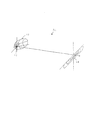
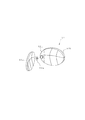
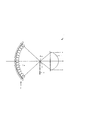
まず、図25に示す車両前照灯1は、前方に向かって凹状の基板表面に、複数個のLED2aを並べて実装した光源モジュール2と、光源モジュール2の前方に配置された投影レンズ3と、投影レンズ3の光源側の焦点位置F付近に配置された遮光部材4と、から構成されている。
And as such a vehicle headlamp, the vehicle headlamp shown, for example in FIGS. 25-27 is disclosed.
First, the
上記光源モジュール2の各LED2aは、それぞれその光軸が投影レンズ3の焦点位置Fに向いて配置されており、それぞれ図示しない駆動部から駆動電流が供給されることにより、発光するようになっている。
上記投影レンズ3は、凸レンズから構成されており、光源モジュール2の各LED2aから出射する光を、前方に向かって集束して照射するようになっている。
上記遮光部材4は、すれ違いビームの配光パターンとなるようなカットオフを形成するように、その端縁4aが形成されている。
Each LED 2a of the
The
The
このような構成の車両前照灯1によれば、光源モジュール2の各LED2aが駆動電流を供給されることにより発光し、各LED2aから出射した光が、それぞれ投影レンズ3の焦点位置Fに向かって進んで、投影レンズ3により集束され前方に向かって照射される。
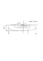
その際、上記光は、遮光部材4によりカットオフを形成されることにより、図26に示すように、所謂すれ違いビームの配光パターンLの範囲で、前方に向かって照射されることになる。これにより、対向車や歩行者に対して眩惑光を与えないようになっている。
According to the
At that time, the light is cut off by the
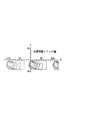
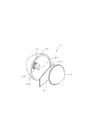
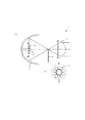
また、図27に示す車両前照灯5は、前方に延びる中心軸の周りに環状に配置された複数個のLED6aから成る光源モジュール6と、光源モジュール6からの光を前方に向かって反射させるリフレクタ7と、リフレクタ3からの反射光を集束させる投影レンズ3と、すれ違い配光のためのカットオフを形成する遮光部材4と、から構成されている。
A
上記光源モジュール6の各LED6aは、図27(B)に示すように、それぞれ光軸が中心軸から半径方向外側に向かって延びるように配置されている。
上記リフレクタ7は、例えば回転楕円面から構成されており、その第一の焦点位置付近に光源モジュール6の各LED6aが配置されていると共に、その第二の焦点位置が投影レンズ3の光源側の焦点位置付近に位置するようになっている。
As shown in FIG. 27B, the LEDs 6a of the
The
このような構成の車両前照灯5によれば、光源モジュール6の各LED6aが駆動電流を供給されることにより発光し、各LED6aから出射した光が、それぞれリフレクタ7で反射されて、リフレクタ7の第二の焦点即ち投影レンズ3の焦点位置Fに向かって進んで、投影レンズ3により集束されて、前方に向かって照射される。
その際、上記光は、遮光部材4によりカットオフを形成されることにより、図26に示すように、所謂すれ違いビームの配光パターンLの範囲で、前方に向かって照射されることになる。これにより、対向車や歩行者に対して眩惑光を与えないようになっている。
According to the
At that time, the light is cut off by the
しかしながら、このような構成の車両前照灯1においては、何れもハロゲン電球や放電灯を前提とした光学系から構成されていることから、光源としてLEDを使用するには適しておらず、所望の配光パターンを形成することが困難であった。このため、個々のLEDから出射する光を効率良く利用して前方に向かって照射することができない。
However, the
さらに、図26に示すように、前照灯のすれ違いビームにおいては、中心方向即ち所謂HV付近においては、例えば6000cd乃至20000cd程度の光度が必要である。
これに対して、光を投影レンズによって集束させる光学系においては、光度値は投影レンズの焦点位置付近での光の密度(光束発散度)と灯具面積に比例する関係にある。従って、ハロゲン電球やHID等の放電灯と比較して輝度が著しく低いLEDを光源として使用する場合、リフレクタや投影レンズを利用する前述した従来の光学系により上述した光度を得るためには、光学系の大きさが非常に大きくなってしまう。
Furthermore, as shown in FIG. 26, in the passing beam of the headlamp, a luminous intensity of, for example, about 6000 cd to 20000 cd is required in the central direction, that is, in the vicinity of the so-called HV.
On the other hand, in an optical system that focuses light by a projection lens, the luminous intensity value is proportional to the light density (light flux divergence) and the lamp area in the vicinity of the focal position of the projection lens. Therefore, in the case where an LED having a remarkably low brightness as compared with a discharge lamp such as a halogen bulb or HID is used as a light source, in order to obtain the above-described luminous intensity by the above-described conventional optical system using a reflector or a projection lens, The size of the system becomes very large.
特に、図25に示した車両前照灯1の場合、光源モジュール2の各LED2aと投影レンズ3の焦点位置Fとの距離が大きくなるにつれて焦点位置F付近における光の密度が疎になってしまうので、高い光度を得ることができなくなってしまう。逆に、光源モジュール2と焦点位置Fを近づけると、光源モジュール2上に集積できるLED2aの個数が少なくなってしまう。このようにして、車両前照灯1においては、何れの場合にも、所望の光度を得ることは困難である。
In particular, in the case of the
また、図27に示した車両用前照灯5の場合、リフレクタ7によって光源モジュール6の各LED6aが拡大投影されることになってしまい、同様にして所望の光度を得ることは困難である。
In the case of the
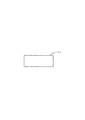
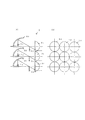
これに対して、例えば図28に示すような車両前照灯8も考えられる。
図28において、車両前照灯8は、縦横にマトリックス状に配置された複数個のLED9aに対して、それぞれリフレクタ9b,投影レンズ9c及び遮光部材9dを設けて、各LED9a毎に対応するリフレクタ9b及び投影レンズ9cにより、各LED9aの像を前方に向かって投影するように構成されている。
しかしながら、このような構成の車両前照灯8においては、リフレクタ9b及び投影レンズ9cによる光学系が、車両前照灯5の場合と同様に、ハロゲン電球や放電灯を前提とした構成であることから、同様に光源としてLEDを使用するには適していない。
On the other hand, for example, a
In FIG. 28, a
However, in the
さらに、上述した各車両前照灯1,5,8においては、対向車の運転者を幻惑しないように、道路の一側(左側通行の場合には、左側)をより明るく照射するようなすれ違いビームの配光パターンを画成するために、遮光部材4,9dを備えており、この遮光部材4,9dにより不要な光を遮断することにより、上述したすれ違いビームの配光パターンを得るようにしている。 その際、すれ違いビームの配光パターンに対してカットオフを形成するためには、各LED2a,6a,9aの光軸付近の最も輝度が高い部分で遮光部材4,9dによりカットオフを形成する必要がある。従って、各LED2a,6a,9aからの発光光量のうち、例えば約40%近い光量が、遮光部材4,9dにより遮断され、損失光となってしまうことから、LEDの面発光という光学的特徴を生かすことができず、光の利用効率が非常に低くなってしまう。
Further, in each of the
これに対して、遮光部材4,9dを使用せずに、リフレクタ7,9bのみによって配光パターンの制御を行なうようにすれば、損失は最低限に抑制され得るので、光の利用効率は約70%程度まで高めることができるが、個々のLEDの輝度が低いことから、H線(水平線)やエルボライン(斜め15度の傾斜線)における明暗境界線での十分なコントラストを得ることが困難になってしまう。
On the other hand, if the light distribution pattern is controlled only by the
本発明は、以上の点から、光源として複数個のLED素子を使用して、所望の配光パターンを得るようにした、前照灯,補助前照灯等に適した車両前照灯を提供することを目的としている。 In view of the above, the present invention provides a vehicle headlamp suitable for a headlamp, an auxiliary headlamp, and the like that uses a plurality of LED elements as a light source to obtain a desired light distribution pattern. The purpose is to do.
上記目的は、本発明によれば、光源としてLEDを備えた複数個の光源モジュール及び上記複数個の光源モジュールのそれぞれに対応した個数の光学系からなり、各光源モジュールからの光をそれぞれ前方に向かって照射する照明部を、配光パターンにおける集光領域、拡散領域、及び中間領域のそれぞれの照射領域に対応して領域ごとに異なる光学系の構成を有し当該領域ごとに異なる配光を形成するものとして少なくとも各領域一組ずつ備えており、上記それぞれの照射領域に対応した各照明部の照射光を重ね合わせることにより、全体として一つの配光パターンを形成し、上記集光領域に光を照射する照明部が、
すれ違いビームの配光パターンに対応した形状を有する遮光部材付近を焦点位置とする投影レンズを光学系として備え、上記配光パターンのうち中心付近において集光したエルボラインをを有する部分を形成し、上記拡散領域に光を照射する照明部が、一つ以上の直線的な稜線のある発光部を有する光源モジュールを備え、上記発光部付近を焦点位置として上記光源モジュールからの光を前方に向かって投影して照射するリフレクタを光学系として備え、上記リフレクタにより照射される上記発光部の投影像により配光パターンのうち水平線方向に拡散した部分を形成し、上記中間領域に光を照射する照明部が、光源モジュールの発光面が後方に向かって傾斜しており、上記光源モジュールの光を反射するリフレクタと灯具光軸に沿って配置された遮光部材と上記遮光部材付近を焦点とし上記リフレクタの反射光を投影する投影レンズを光学系として備え、上記配光パターンのうち上記集光領域と拡散領域の中間となる大きさを持ち水平ラインのカットオフを形成することを特徴とする、車両前照灯により、達成される。
According to the present invention, the above object comprises a plurality of light source modules each having an LED as a light source and a number of optical systems corresponding to each of the plurality of light source modules. The illumination unit that irradiates toward the light distribution pattern has a different optical system configuration corresponding to each irradiation region of the condensing region, the diffusion region, and the intermediate region in the light distribution pattern. At least one set of each area is provided to form, and by superimposing the irradiation light of each illumination unit corresponding to each of the above irradiation areas, a single light distribution pattern is formed as a whole, and The illumination unit that irradiates light
A projection lens having a focus position near the light-shielding member having a shape corresponding to the light distribution pattern of the passing beam is provided as an optical system, and a portion having an elbow line condensed near the center of the light distribution pattern is formed. The illumination unit that irradiates light to the diffusion region includes a light source module having a light emitting unit having one or more linear ridges, and the light from the light source module is directed forward with the vicinity of the light emitting unit as a focal position. An illuminating unit that includes a reflector that projects and irradiates as an optical system, and that forms a diffused portion of the light distribution pattern in the horizontal direction in the projected image of the light emitting unit irradiated by the reflector, and irradiates the intermediate region with light However, the light emitting surface of the light source module is inclined rearward and is disposed along the reflector and the light axis of the lamp that reflects the light of the light source module. The light shielding member and the shielding member near the focal point with a projection lens for projecting the reflected light of the reflector as the optical system, the horizontal has an indeterminate become the size of the condensing region and the diffusion region of the light distribution pattern This is achieved by a vehicle headlamp, characterized in that it forms a cut-off of the line .
本発明による車両前照灯は、好ましくは、さらに、補助ランプの配光領域に対して光を照射するために最適化された光源モジュール及び光学系を備えている。 The vehicle headlamp according to the present invention preferably further comprises a light source module and an optical system optimized for irradiating light to the light distribution area of the auxiliary lamp.
本発明による車両前照灯は、好ましくは、上記補助ランプの配光領域が、データイムランニングランプ,フォグランプまたはコーナーリングランプの配光領域である。 In the vehicle headlamp according to the present invention, preferably, the light distribution area of the auxiliary lamp is a light distribution area of a data imprinting lamp, a fog lamp, or a cornering lamp.
本発明による車両前照灯は、好ましくは、さらに、任意の配光領域に対して光を照射するために最適化され、且つ着脱可能に配置された光源モジュール及び光学系を備えている。 The vehicle headlamp according to the present invention preferably further includes a light source module and an optical system that are optimized for irradiating light to an arbitrary light distribution region and are detachably disposed.
本発明による車両前照灯は、好ましくは、各光源モジュールが、光を照射する配光領域に対応して、それぞれLEDチップ数,配置及び構造が最適化された異なる種類のパッケージとして構成されている。 The vehicle headlamp according to the present invention is preferably configured as a different type of package in which each light source module is optimized for the number of LED chips, the arrangement, and the structure corresponding to the light distribution area to which light is emitted. Yes.
上記構成によれば、配光パターンを複数の領域に分割して、各領域に対して、それぞれ光源モジュール及び光学系を設ける。そして、これらの光源モジュール及び光学系をそれぞれ対応する領域に関して最適化することによって、配光パターンの各領域がそれぞれ所望の光度分布を備えた配光特性となる。
これにより、車両前照灯が全体として、複数組の光源モジュール及び光学系の組合せによって、所望の光度分布を有する所望の配光パターンを形成することができる。その際、各光源モジュールの各LEDは、光学系と共に、対応する配光パターンの領域に対して最適化されることにより、各LEDからの光の利用効率が向上し、より明るい照射光が得られることになる。
According to the above configuration, the light distribution pattern is divided into a plurality of regions, and the light source module and the optical system are provided for each region. Then, by optimizing these light source modules and optical systems with respect to the corresponding regions, each region of the light distribution pattern has a light distribution characteristic having a desired light intensity distribution.
As a result, the vehicle headlamp as a whole can form a desired light distribution pattern having a desired light intensity distribution by a combination of a plurality of sets of light source modules and optical systems. At that time, each LED of each light source module is optimized for the area of the corresponding light distribution pattern together with the optical system, thereby improving the light use efficiency from each LED and obtaining brighter irradiation light. Will be.
上記各光源モジュール及び光学系が、それぞれ配光パターンの集光域,拡散域に光を照射する場合には、各光源モジュール及び光学系が、それぞれ配光パターンの集光域及び拡散域に対して最適化されることにより、それぞれ集光域,拡散域に所望の光度分布で光を照射する。これにより、全体として所望の光度分布の配光パターンを形成することができる。 When each of the light source modules and the optical system irradiate light to the light collection area and the diffusion area of the light distribution pattern, respectively, each light source module and the optical system respectively correspond to the light collection area and the diffusion area of the light distribution pattern. By optimizing the light, the light is irradiated with a desired light intensity distribution in the light converging area and the diffusion area, respectively. Thereby, it is possible to form a light distribution pattern having a desired light intensity distribution as a whole.
上記各光源モジュール及び光学系が、それぞれ配光パターンの集光域,拡散域及び中間域に光を照射する場合には、各光源モジュール及び光学系が、それぞれ配光パターンの集光域,拡散域及び中間域に対して最適化されることにより、それぞれ集光域,拡散域及び中間域に所望の光度分布で光を照射する。これにより、全体として所望の光度分布の配光パターンを形成することができると共に、中間域により集光域と拡散域を連続的に滑らかなコントラストで接続することができる。 When each of the light source modules and the optical system irradiate light in the light collection area, the diffusion area, and the intermediate area of the light distribution pattern, each light source module and the optical system respectively emit the light collection pattern in the light collection pattern and the diffusion area. By optimizing with respect to the area and the intermediate area, light is irradiated with a desired light intensity distribution to the condensing area, the diffusion area, and the intermediate area, respectively. As a result, a light distribution pattern having a desired light intensity distribution can be formed as a whole, and the condensing region and the diffusion region can be continuously connected with a smooth contrast by the intermediate region.
上記配光パターンの集光域に光を照射するための光源モジュールが、すれ違いビームの配光パターンと同様の形状を備えた遮光部材を備えており、対応する光学系が、光を集束する投影レンズから構成されている場合には、当該光源モジュールの各LEDからの光が、遮光部材によりカットオフを形成され、さらにカットオフによる発光形状が投影レンズにより集束されて、前方に向かって投影されることにより、簡単な構成によって、例えば中心付近にてコントラストの高い明暗境界線を形成することができるので、集光域に適した配光パターンを形成することが可能である。 The light source module for irradiating light to the light converging area of the light distribution pattern includes a light shielding member having the same shape as the light distribution pattern of the low beam, and the corresponding optical system projects the light to focus the light. In the case of a lens, the light from each LED of the light source module is cut off by the light shielding member, and the light emission shape by the cutoff is converged by the projection lens and projected forward. Thus, with a simple configuration, for example, a high-contrast bright / dark boundary line can be formed in the vicinity of the center, so that a light distribution pattern suitable for the light collection region can be formed.
上記配光パターンの拡散域に光を照射するための光源モジュールが、一つの直線的な稜線を備えた一方向に長い発光形状を有しており、対応する光学系が、光源モジュールからの光を反射するリフレクタから構成されている場合には、例えばLEDチップを直線状に配置した光源モジュールを使用して、その直線的な稜線がリフレクタにより反射され、前方に向かって照射されることにより、光源モジュールからの光を効率良く前方に反射させることができると共に、直線的な稜線をカットオフライン付近に投影することで、コントラストの高い明暗境界を形成することができるので、水平線方向に関して拡散し(カットオフラインに明暗差を有する)、拡散域に適した配光パターンを形成することができる。さらに、光源モジュールが実質的に面発光、完全拡散発光であることから、リフレクタは光源全体を覆う必要がなく、平面に近い形状となるため、車両前照灯全体を薄型に構成することができる。 The light source module for irradiating light to the diffusion region of the light distribution pattern has a long light emission shape in one direction with one linear ridgeline, and the corresponding optical system has a light from the light source module. In the case of a light source module in which LED chips are arranged in a straight line, for example, the linear ridge line is reflected by the reflector and irradiated forward, Light from the light source module can be efficiently reflected forward, and by projecting a straight ridge line near the cutoff line, a high-contrast light / dark boundary can be formed. A light distribution pattern suitable for the diffusion region can be formed. Furthermore, since the light source module is substantially surface emitting and completely diffuse light emitting, the reflector does not need to cover the entire light source and has a shape close to a flat surface, so that the entire vehicle headlamp can be configured to be thin. .
上記配光パターンの中間域に光を照射するための光学系が、集光域と拡散域の配光特性を連続的に滑らかに接続するように、リフレクタ及び投影レンズから構成されている場合には、リフレクタにより拡散し投影レンズにより集束されて、前方に向かってやや拡散して照射される。カットオフはレンズ焦点における遮光版により形成するため、集光域におけるコントラストの高い明暗境界線を形成する配光パターンと、拡散域における水平方向に拡散した配光パターンとの間を、円滑に接続することができる。 When the optical system for irradiating light to the intermediate region of the light distribution pattern is composed of a reflector and a projection lens so as to continuously and smoothly connect the light distribution characteristics of the condensing region and the diffusion region. Is diffused by a reflector, converged by a projection lens, and slightly diffused forward. Since the cut-off is formed by a light-shielding plate at the lens focal point, a smooth connection is established between a light distribution pattern that forms a high-contrast light / dark boundary line in the light converging area and a light distribution pattern that diffuses in the horizontal direction in the diffusion area. can do.
さらに、補助ランプの配光領域に対して光を照射するために最適化された光源モジュール及び光学系を備えており、好ましくは、上記補助ランプの配光領域が、データイムランニングランプ,フォグランプまたはコーナーリングランプの配光領域である場合には、本車両前照灯内に組み込まれた光源モジュール及び光学系により、補助ランプの機能を実現することが可能となり、車両用灯具全体が小型に構成されることになり、車両用灯具そして自動車のデザインの自由度が大きくなる。 Further, the light source module and the optical system optimized for irradiating light to the light distribution area of the auxiliary lamp are provided. Preferably, the light distribution area of the auxiliary lamp is a data imprinting lamp, a fog lamp, or In the case of the light distribution area of the cornering lamp, the light source module and the optical system incorporated in the vehicle headlamp can realize the function of the auxiliary lamp, and the entire vehicle lamp is configured to be small. As a result, the degree of freedom in designing vehicle lamps and automobiles is increased.
さらに、任意の配光領域に対して光を照射するために最適化され、且つ着脱可能に配置された光源モジュール及び光学系を備えている場合には、必要に応じて補助ランプやその他の車両用灯具の機能を付加したり、取り外したりすることができるので、任意の機能を備えた車両用灯具を容易に構成することが可能になる。 Furthermore, when it is equipped with a light source module and an optical system that are optimized for irradiating light to an arbitrary light distribution area and are detachably disposed, auxiliary lamps and other vehicles are provided as necessary. Since the function of the lamp can be added or removed, a vehicular lamp having an arbitrary function can be easily configured.
各光源モジュールが、光を照射する配光領域に対応して、それぞれLEDチップ数,配置及び構造が最適化された異なる種類のパッケージとして構成されている場合には、各光源モジュールは、光を照射すべき配光パターンの所定の領域に対して、これらのLEDチップ数,配置及び構造を最適化したパッケージとして構成されているので、このようなパッケージの種類の組合せによって、車両前照灯を構成することができる。 When each light source module is configured as a different type of package in which the number, arrangement, and structure of the LED chips are optimized, corresponding to the light distribution area that emits light, each light source module emits light. Since it is configured as a package in which the number, arrangement and structure of these LED chips are optimized for a predetermined area of the light distribution pattern to be irradiated, the vehicle headlamp can be used by combining such package types. Can be configured.
このようにして、本発明によれば、光源としてLEDを使用した光源モジュールにより、各LEDからの光を対応する光学系を介して配光パターンの所定の領域に対して照射し、その際光源モジュール及び光学系がそれぞれ対応する配光パターンの領域に関して最適化されていることにより、複数組の光源モジュール及び光学系を組み合わせることによって、全体として所望の発光形状及び輝度分布を備えた配光特性を実現することができる。
従って、光源としてハロゲン電球やHID等の放電灯と比較して輝度の低いLEDを使用しても、十分な最大光度を得ることができるので、高効率で且つ小型,薄型の車両前照灯を実現することができる。
さらに、光源モジュールの組合せにより、所望の配光特性を形成することができるので、配光の自由度そして車両前照灯のデザインの自由度を大きくすることができる。
Thus, according to the present invention, a light source module using LEDs as light sources irradiates light from each LED to a predetermined region of a light distribution pattern via a corresponding optical system, and at that time, the light source By optimizing the area of the light distribution pattern corresponding to each module and optical system, the light distribution characteristics with the desired light emission shape and luminance distribution as a whole can be obtained by combining multiple sets of light source modules and optical systems. Can be realized.
Therefore, even if an LED having a lower brightness than a discharge lamp such as a halogen bulb or an HID is used as a light source, a sufficient maximum luminous intensity can be obtained. Therefore, a highly efficient, small and thin vehicle headlamp can be obtained. Can be realized.
Furthermore, since a desired light distribution characteristic can be formed by the combination of the light source modules, the degree of freedom of light distribution and the degree of freedom of design of the vehicle headlamp can be increased.
以下、この発明の好適な実施形態を図1乃至図24を参照しながら、詳細に説明する。
尚、以下に述べる実施形態は、本発明の好適な具体例であるから、技術的に好ましい種々の限定が付されているが、本発明の範囲は、以下の説明において特に本発明を限定する旨の記載がない限り、これらの態様に限られるものではない。
Hereinafter, a preferred embodiment of the present invention will be described in detail with reference to FIGS.
The embodiments described below are preferable specific examples of the present invention, and thus various technically preferable limitations are given. However, the scope of the present invention particularly limits the present invention in the following description. As long as there is no description of the effect, it is not restricted to these aspects.
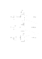
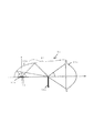
図1は、本発明による車両前照灯の第一の実施形態の構成を示している。 図1において、車両前照灯10は、三組の照明部11,21,31から構成されている。
FIG. 1 shows the configuration of a first embodiment of a vehicle headlamp according to the present invention. In FIG. 1, the
第一組の照明部11は、所謂すれ違いビームの配光パターンのうち、エルボライン等の明暗境界線を含む最大光度である集光域に対して光を照射するように構成されている。
また、第二組の照明部21は、上記配光パターンのうち、エルボラインの必要のない広い範囲の領域である拡散域に対して光を照射するようになっている。
さらに、第三組の照明部31は、上記配光パターンのうち、上記集光域と拡散域の配光のコントラストを円滑に接続するように、その間の中間域に対して光を照射するようになっている。
The first set of illuminating
Moreover, the 2nd set of
Further, the third set of
まず、集光域のための第一組の照明部11について説明する。
第一組の照明部11は、図2に示すように、光源モジュール12及び光学系13から構成されている。
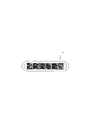
光源モジュール12は、図3に示すように、LEDチップを蛍光体により包囲したLEDから成る発光部12aを備えており、例えば樹脂製のレンズハウス12bによりパッケージ化されている。上記発光部12aは、外部からリード12cを介して給電されることにより、LEDチップから出射した光が蛍光体に当たり、LEDチップからの光と蛍光体による励起光の混色光が外部に出射するようになっている。
First, the 1st set of
As shown in FIG. 2, the first set of
As shown in FIG. 3, the
上記光源モジュール12は、さらに発光部12aの前方にレンズ12d及び遮光部材12eを備えており、発光部12aからの光を、遮光部材12eにより光を切り取りカットオフを形成しており、水平ライン及び凸レンズ(投影レンズ)を用いて投影するだけですれ違いビームの配光パターンの特徴である中心から例えば15度で斜め上に延びるエルボラインを成立するようになっている。
The
上記光学系13は、凸レンズから成る投影レンズであって、図2に示すように、光源モジュール12の中心軸上に光軸が一致するように、そしてその光源側の焦点位置が光源モジュール12の発光部12a手前の遮光部材12e付近に位置するように、配置されている。
これにより、光源モジュール12の各LED12aからの光が光学系13により前方に向かって集光されることにより、図2にて符号Laで示す配光パターン領域(集光域)を形成するようになっている。
The
Thereby, the light from each LED 12a of the
ここで、光学系13は、集光光学系であることから、他の構成の集光光学系も使用することが可能ではあるが、配光パターンにおける集光域での最大光度値は、二次光学系即ち光学系13の焦点位置付近における輝度と、光学系13の面積に比例することから、光源モジュール12の発光部12aを投影レンズによって直接に集光域に向かって投影する図2に示した構成が、最も効率良く最大輝度を得ることができる。
Here, since the
これに対して、光源モジュールのレンズ外面付近に配置された遮光部材12e付近に投影レンズの焦点位置を配置した場合には、輝度が大幅に低下することになるので、最大光度値も大幅に低下してしまう。
また、リレーレンズを使用して、発光部12aの像を遮光部材12e付近に結像させて、この像を投影レンズにより集光域に向かって投影するような構成の光学系の場合には、光学系が複雑になって、部品コスト及び組立コストが高くなり、さらに車両前照灯全体の奥行きが大きくなってしまうと共に、焦点位置における発光部12aの像の輝度が低下することになり、集光域における最大光度値も同様に低下してしまう。
On the other hand, when the focal position of the projection lens is arranged in the vicinity of the light shielding member 12e arranged in the vicinity of the lens outer surface of the light source module, the luminance is greatly reduced, so that the maximum luminous intensity value is also greatly reduced. Resulting in.
In the case of an optical system having a configuration in which a relay lens is used to form an image of the light emitting unit 12a in the vicinity of the light shielding member 12e and this image is projected toward the light collection region by the projection lens. The optical system becomes complicated, the parts cost and the assembly cost increase, the depth of the entire vehicle headlamp increases, and the brightness of the image of the light emitting unit 12a at the focal position decreases. Similarly, the maximum luminous intensity value in the light region also decreases.
ここで、上記第一組の照明部11は、配光パターンの集光域にて任意の輝度分布を付与することは困難である。このため、図4に示すように、複数個(図示の場合、4個)の第一組の照明部11a,11b,11c,11dを設けて、光源モジュール12a’,12b’,12c’,12d’からの光L1,L2,L3,L4を、それぞれ互いに異なる焦点距離の光学系13a,13b,13c,13dにより前方に向かって投影することにより、図5に示すように、各照明部11a,11b,11c,11d毎に照射範囲を適宜に重ねて設定することにより、全体として輝度分布即ちグラデーションを有する配光特性を備えることができる。
Here, it is difficult for the first set of
次に、拡散域のための第二組の照明部21について説明する。
第二組の照明部21は、図6に示すように、光源モジュール22及び光学系23から構成されている。
光源モジュール22は、LEDによる例えば長方形等の一つ以上の直線的な稜線のある発光形状、例えば図7に示すように長方形の発光部22aを備えている。
Next, the second set of
As shown in FIG. 6, the second set of
The
また、光学系23は、この場合、前方に向かって凹状の例えば回転放物面や回転楕円面などの組み合わせから成るリフレクタから構成されており、光源モジュール22の軸に対向して、その焦点位置が光源モジュール22の発光部22a付近に位置するように、配置されている。
これにより、光源モジュール22の発光部22aからの光が、光学系23により反射され、図6にて符号Lbで示す配光パターン領域(拡散域)を形成するようになっている。
Further, in this case, the optical system 23 is composed of a reflector made of a combination of, for example, a rotating paraboloid or a rotating ellipsoid, which is concave toward the front, and the focal position of the optical system 23 is opposed to the axis of the
Thereby, the light from the light emission part 22a of the
この場合、光源モジュール22が面発光であり、ランバーシアン指向特性を備えている利点を生かして、光源モジュール22の発光部22aから出射する光の利用効率は、約70%以上になると共に、リフレクタの形状を適宜に選択することにより、所望の配光パターンを形成することができる。
その際、光源モジュール22の発光部22aの直線的な稜線を水平方向に配置して、光学系23により前方に向かって投影することにより、この稜線を配光パターンの水平ラインのカットオフ形成に利用することができる。
In this case, taking advantage of the fact that the
At that time, a linear ridge line of the light emitting unit 22a of the
さらに、上記第二組の照明部21は、好ましくは上記光学系23を構成するリフレクタが、複数の反射面に分割されたマルチリフレクタとして構成され、個々の反射面が適宜に形成されることによって、光源モジュール22の発光部22aを図8に示すように、投影する。この場合、反射する位置により発光部22aの投影像は回転して投影される。
これにより、配光パターンの拡散域は、各反射面による発光部22aの投影像が互いに重ね合わせられることによって、図9に示すように、光度分布即ちグラデーションを有する配光特性を備えることができる。
Further, in the second set of
Thereby, the diffusion area of the light distribution pattern can be provided with a light distribution characteristic having a luminous intensity distribution, that is, a gradation, as shown in FIG. 9, by superimposing the projected images of the light emitting portions 22a by the respective reflecting surfaces. .
尚、光源モジュール22の発光部22aは、長方形に限らず、図10に示すように、ほぼ半円形状の外形を有するように形成されていてもよく、また図11に示すように、複数個のLEDチップを一方向に並べて配置するようにしてもよい。
In addition, the light emission part 22a of the
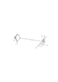
最後に、中間域のための第三組の照明部31について説明する。
第三組の照明部31は、図12に示すように、光源モジュール32及び光学系33から構成されている。
光源モジュール32は、図2における光源モジュール12から遮光部材12eを除いた構成であって、発光部12aの表面が、光学系33の光軸に沿って配置されている。
尚、この場合、光源モジュール32の発光部32aの形状は、制約がないが、光学系33の投影レンズ33bへの入射効率を高め、更に光学系サイズを小型化するためには、発光部32aはできるだけ小さく、輝度が高いものが好ましい。
Finally, the third set of
As shown in FIG. 12, the third set of
The
In this case, the shape of the light emitting unit 32a of the
光学系33は、リフレクタ33a,投影レンズ33b及び遮光部材33cから構成されている。
ここで、リフレクタ33aは例えば回転楕円面から構成されており、一方の焦点位置が光源モジュール32の発光部32aの中心付近に、他方の焦点位置が前方にて光学系33の光軸上に位置するように配置されている。
投影レンズ33bは、凸レンズであって、その光源側の焦点位置が、リフレクタ33aの前側の焦点位置付近に位置するように配置されている。
さらに、上記遮光部材33cは、投影レンズ33bの光源側の焦点位置付近に配置されており、その端縁33dが上端にてカットオフを形成するようになっている。
The
Here, the reflector 33a is composed of, for example, a spheroid, and one focal position is located near the center of the light emitting unit 32a of the
The
Further, the light shielding member 33c is disposed in the vicinity of the focal position on the light source side of the
尚、上述した構成では、発光部32aが上向きに配置されており、リフレクタ33aが上半分のみに配置されているが、これに限らず、図13に示すように、上記発光部32aに加えて、下向きの発光部32a’を備えると共に、リフレクタ32aと上下に対した、下半分のリフレクタ33a’を備えるようにしてもよい。 In the above-described configuration, the light emitting unit 32a is arranged upward, and the reflector 33a is arranged only in the upper half. However, the present invention is not limited to this, as shown in FIG. 13, in addition to the light emitting unit 32a. In addition to the downward light emitting section 32a ′, a lower half reflector 33a ′ with respect to the reflector 32a and the upper and lower sides may be provided.
また、図14に示すように、遮光部材33cを光軸に沿って配置して、その端縁33dが前端にてカットオフを形成するようにしてもよい。これにより、遮光部材33dの表面の一部に入射する光が、反射されて、前方に向かって照射されることにより、光の利用効率を50%以上に高めることができる。 Moreover, as shown in FIG. 14, the light shielding member 33c may be disposed along the optical axis, and the end edge 33d may form a cutoff at the front end. Thereby, the light incident on a part of the surface of the light shielding member 33d is reflected and irradiated toward the front, whereby the light utilization efficiency can be increased to 50% or more.
その際、図15に示すように、カットオフラインにおけるコントラストをより高めるために、発光部32aが後方に向かって僅かに傾斜して配置されていてもよい。
尚、図16における光学系ではLED光源が面発光であり、反射面はレンズ中心より上方もしくは下方にしか存在しない場合、投影レンズ33bの中心より下面もしくは上面にしか光が入射しなくなるため、投影レンズ33bの上方半分もしくは下方半分をカットすることにより、上下方向に関して小型化を図ることができると共に、より高光度の配向パターンを得るために、複数個の照明部31を上下方向に重ねて配置する場合に、上下方向により密接して配置することが可能になる。
In that case, as shown in FIG. 15, in order to raise the contrast in a cut-off line more, the light emission part 32a may be arrange | positioned slightly inclined toward back.
In the optical system in FIG. 16, when the LED light source is surface emitting and the reflecting surface exists only above or below the center of the lens, light is incident only on the lower surface or the upper surface from the center of the
本発明実施形態による車両前照灯10は、以上のように構成されており、各照明部11,21,31の光源モジュール12,22,32がそれぞれ給電されることにより発光する。
これにより、光源モジュール12の発光部12aから出射した光は、遮光部材12eによりカットオフを形成され、光学系13の投影レンズにより集光されて、前方に向かって照射され、配光パターンの集光域Laを形成する。
また、光源モジュール22の発光部22aから出射した光は、光学系23のリフレクタにより反射されることにより、前方に向かって照射され、配光パターンの拡散域Lbを形成する。
さらに、光源モジュール32の発光部32aから出射した光は、光学系33のリフレクタ33aにより反射され、さらに投影レンズ33bにより集束されると共に、遮光部材33cによりカットオフを形成されて、前方に向かって照射され、配光パターンの集光域Laと拡散域Lbの間の中間域を形成する。
The
As a result, the light emitted from the light emitting unit 12a of the
Further, the light emitted from the light emitting unit 22a of the
Further, the light emitted from the light emitting unit 32a of the
これにより、各照明部11,21,31からの照射光が互いに重なりあって、前方に向かって所謂すれ違いビームの配光パターンが形成され得ることになる。 その際、配光パターンの複数の領域、即ち集光域,拡散域及びその間の中間域が、それぞれ第一組の照明部11,第二組の照明部21及び第三組の照明部31によって形成されることになる。ここで、各照明部11,21,31がそれぞれ対応する領域に最適化して構成されているので、各領域そして配光パターン全体が所望の光度分布で、そして最大光度にて形成されることになる。
Thereby, the irradiation light from each
このようにして、本発明による車両前照灯10によれば、光源として複数個のLEDを使用して、所望の配光パターン、例えば所謂すれ違いビームの配光パターンを得ることができる。
Thus, according to the
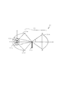
図17は、本発明による車両前照灯の第二の実施形態の構成を示している。
図17において、車両前照灯40は、前述した車両前照灯10の具体的な実施形態であって、図1に示した車両前照灯10と同様に、三組の照明部41,51,61から構成されている。
FIG. 17 shows the configuration of the second embodiment of the vehicle headlamp according to the present invention.
In FIG. 17, a
この場合、集光域に対応する第一組の照明部41は、図1に示した車両前照灯の第一組の照明部11とほぼ同様に構成されており、左8度から右8度までの範囲に対して光を照射するようになっている。
また、拡散域に対応する第二組の照明部51は、図1に示した車両前照灯の第二組の照明部21とほぼ同様に構成されており、左50度から右50度までの範囲に対して光を照射するようになっている。
さらに、中間域に対応する第三組の照明部61は、図1に示した車両前照灯の第三組の照明部31とほぼ同様に構成されており、左20度から右20度までの範囲に対して光を照射するようになっている。
尚、各領域、即ち集光域,中間域及び拡散域に対する配光割合(光束割合)は、好ましくは1:2:4となるように設定されている。
In this case, the first set of
Further, the second set of illuminating parts 51 corresponding to the diffusion area is configured in substantially the same manner as the second set of illuminating
Further, the third set of illumination units 61 corresponding to the intermediate area is configured in substantially the same manner as the third set of
The light distribution ratio (light flux ratio) for each region, that is, the light condensing region, the intermediate region, and the diffusion region is preferably set to be 1: 2: 4.
上記第一組の照明部41は、図18に示すように、複数個(図示の場合、4個)の光源モジュール42a,42b,42c,42dと、それぞれ対応する投影レンズ43a,43b,43c,43dと、から構成されている。 各光源モジュール42a,42b,42c,42dは、それぞれ車両前照灯10の第一組の照明部11における光源モジュール12と同様に構成されている。
また、各投影レンズ43a,43b,43c,43dは、図4に示す構成と同様にして、互いに異なる焦点距離を有している。
そして、各投影レンズ43a,43b,43c,43dの焦点距離を適宜に選定することによって、スクリーン上における光度及び投影サイズが得られるようになっている。
As shown in FIG. 18, the first set of
Each
Then, by appropriately selecting the focal lengths of the
上記第二組の照明部51は、図19に示すように、複数個(図示の場合、2個)の光源モジュール52a,52bと、それぞれ対応するリフレクタ53a,53bと、から構成されている。
各光源モジュール52a,52bは、それぞれ車両前照灯10の第二組の照明部21における光源モジュール22と同様に構成されており、左右方向に背中合わせに配置されている。
ここで、各光源モジュール52a,52bの発光部は、例えば長方形のような一つ以上の直線的な稜線を備えており、この稜線は、従来のハロゲン電球のフィラメントやHIDのアーク電極形状より長く、例えばフィラメントの二倍の長さを有していることが望ましい。特に、図11に示すように、所謂マルチチップタイプの複数個のLEDチップを一つのパッケージ内に直線的に配置した光源パッケージを使用することにより、光源パッケージ自体の光束を増大させることができると共に、車両前照灯全体を小型に構成することが可能である。
As shown in FIG. 19, the second set of illumination units 51 includes a plurality (two in the illustrated example) of light source modules 52a and 52b, and corresponding reflectors 53a and 53b, respectively.
Each light source module 52a, 52b is comprised similarly to the
Here, the light emitting part of each light source module 52a, 52b is provided with one or more linear ridgelines such as a rectangle, and the ridgelines are longer than the filaments of conventional halogen bulbs or arc electrode shapes of HID. For example, it is desirable to have a length twice that of the filament. In particular, as shown in FIG. 11, by using a light source package in which a plurality of so-called multi-chip type LED chips are linearly arranged in one package, the luminous flux of the light source package itself can be increased. It is possible to make the entire vehicle headlamp compact.
また、各リフレクタ53a,53bは、それぞれ車両前照灯10の第二組の照明部21におけるリフレクタ23と同様に構成されており、左右方向に拡るように配置されている。
これにより、上記光源モジュール52a,52bの発光部が比較的長い直線的な稜線を有していても、リフレクタ53a,53bの形状に基づいて、発光部の投影像位置を任意にコントロールすることが可能であり、発光部からの光束の70%以上を前方に向かって照射することができる。
Moreover, each reflector 53a, 53b is comprised similarly to the reflector 23 in the 2nd
Thereby, even if the light emission part of the said light source modules 52a and 52b has a comparatively long linear ridgeline, based on the shape of the reflectors 53a and 53b, the projection image position of a light emission part can be controlled arbitrarily. It is possible, and 70% or more of the light flux from the light emitting part can be irradiated forward.
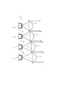
上記第三組の照明部61は、図20に示すように、複数個(図示の場合、3個)の光源モジュール62a,62b,62cと、それぞれ対応するリフレクタ63a,63b,63cと、一つの投影レンズ64と、遮光部材65と、から構成されている。
各光源モジュール62a,62b,62cは、それぞれ車両前照灯10の第三組の照明部31における光源モジュール32と同様に構成されていると共に、中心軸の周りに等角度間隔で配置されている。
ここで、各光源モジュール62a,62b,62cの発光部は、できるだけ小さく、例えば従来のハロゲン電球のフィラメントやHIDのアーク電極形状より小さく選定されていることが望ましい。
As shown in FIG. 20, the third set of illumination units 61 includes a plurality (three in the illustrated example) of
Each
Here, it is desirable that the light emitting portions of the
また、各リフレクタ63a,63b,63cは、それぞれ車両前照灯10の第三組の照明部31におけるリフレクタ33aと同様に構成されており、各光源モジュール62a,62b,62cに対応して、光軸の上方及び両側に配置されている。
Each
さらに、投影レンズ64は、それぞれ車両前照灯10の第三組の照明部31における投影レンズ33bと同様に構成されており、光軸上に一つだけ配置されている。
また、遮光部材65は、それぞれ車両前照灯10の第三組の照明部31における遮光部材33cと同様に構成されており、投影レンズ64の光源側の焦点位置付近に配置されている。
Further, each of the
The light shielding member 65 is configured in the same manner as the light shielding member 33 c in the third set of
尚、直線的な発光部を備える光源モジュールを使用する場合、左右方向に拡る配光パターンを形成するためには、光軸より上方に位置するリフレクタに対応する光源モジュールは、その発光部の長手方向を光軸に対して垂直に配置することが望ましい。また、光軸の側方に位置するリフレクタに対応する光源モジュールは、その発光部の長手方向を光軸に対して平行に配置することが望ましい。これにより、リフレクタによる発光部の投影像が、水平方向に長く延びることになり、配光パターンをより容易に形成することができる。 When a light source module having a linear light emitting unit is used, in order to form a light distribution pattern that expands in the left-right direction, the light source module corresponding to the reflector located above the optical axis is provided on the light emitting unit. It is desirable to arrange the longitudinal direction perpendicular to the optical axis. Moreover, as for the light source module corresponding to the reflector located in the side of an optical axis, it is desirable to arrange | position the longitudinal direction of the light emission part in parallel with respect to an optical axis. Thereby, the projection image of the light emission part by a reflector extends long in a horizontal direction, and a light distribution pattern can be formed more easily.
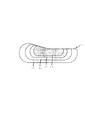
このような構成の車両前照灯40によれば、第一の照明部41は、図21に示すように、集光域に対して光Laを照射し、第二の照明部51は、図22に示すように、拡散域に対して光Lbを照射すると共に、第三の照明部61は、図23に示すように、集光域と拡散域の間の中間域に対して光Lcを照射する。
そして、各照明部41,51,61による配光パターンLa,Lb,Lcを重ね合わせることにより、図24に示すように、すれ違いビームに適した配光パターンLを形成することができる。
According to the
Then, by superimposing the light distribution patterns La, Lb, and Lc by the illuminating
上述した実施形態においては、車両前照灯10,40は、それぞれ集光域,拡散域及び中間域に対応する照明部11,21,31または41,51,61を備えているが、これに限らず、中間域に対応する照明部31,61が省略されていてもよい。また、これらの照明部に対して、例えばデータイムランニングランプ,コーナリングランプの補助灯や、フォグランプ灯の補助前照灯または所謂AFSランプの機能を実現する配光パターンを備える照明部を追加し、あるいは配光パターンをより多くの領域に分割して、分割領域に対して新たな照明部を追加することによって、多機能の配光パターンを一つの車両前照灯により形成することが可能になる。
その際、新たに追加する照明部を着脱可能に構成しておくことにより、当該照明部をオプションにより任意に追加したり、外したりすることができる。
In the above-described embodiment, the
In that case, the illumination part to be newly added is configured to be removable, so that the illumination part can be arbitrarily added or removed as an option.
さらに、上述した実施形態においては、すれ違いビーム用の配光特性として、左側通行の場合に限定して、自動車の前方に向かって右側に関して、対向車に幻惑光を与えないように、遮光板12e,33c,65の端縁が形成されているが、これに限らず、右側通行の場合には、車両前照灯において、遮光板の端縁の配置が左右逆転されることにより、同様の効果が得られることになる。 Furthermore, in the above-described embodiment, the light distribution characteristic for the passing beam is limited to the case of left-hand traffic, and the light-shielding plate 12e is configured so as not to give illusion light to the oncoming vehicle on the right side toward the front of the automobile. , 33c, 65 are formed, but the present invention is not limited to this, and in the case of right-hand traffic, the same effect can be obtained by reversing the arrangement of the edge of the light shielding plate in the vehicle headlamp. Will be obtained.
10 車両前照灯
11 第一組の照明部
12 光源モジュール
12a 発光部(LED)
12e 遮光部材
13 光学系(投影レンズ)
21 第二組の照明部
22 光源モジュール
22a 発光部(LED)
23 光学系(リフレクタ)
31 第三組の照明部
32 光源モジュール
32a,32a’ 発光部(LED)
33 光学系
33a,33a’ リフレクタ
33b 投影レンズ
33c 遮光部材
40 車両前照灯
41 第一組の照明部
42a,42b,42c,42d 光源モジュール
43a,43b,43c,43d 光学系(投影レンズ)
51 第二組の照明部
52a,52b 光源モジュール
53a,53b 光学系(リフレクタ)
61 第三組の照明部
62a,62b,62c 光源モジュール
33 光学系
63a,63b,63c リフレクタ
64 投影レンズ
65 遮光部材
DESCRIPTION OF
12e Light-shielding
21 2nd set of
23 Optical system (reflector)
31 3rd set
33 Optical system 33a, 33a '
51 2nd set illumination part 52a, 52b Light source module 53a, 53b Optical system (reflector)
61 3rd set
Claims (5)
上記それぞれの照射領域に対応した各照明部の照射光を重ね合わせることにより、全体として一つの配光パターンを形成し、
上記集光領域に光を照射する照明部が、
すれ違いビームの配光パターンに対応した形状を有する遮光部材付近を焦点位置とする投影レンズを光学系として備え、上記配光パターンのうち中心付近において集光したエルボラインをを有する部分を形成し、
上記拡散領域に光を照射する照明部が、
一つ以上の直線的な稜線のある発光部を有する光源モジュールを備え、上記発光部付近を焦点位置として上記光源モジュールからの光を前方に向かって投影して照射するリフレクタを光学系として備え、上記リフレクタにより照射される上記発光部の投影像により配光パターンのうち水平線方向に拡散した部分を形成し、
上記中間領域に光を照射する照明部が、
光源モジュールの発光面が後方に向かって傾斜しており、上記光源モジュールの光を反射するリフレクタと灯具光軸に沿って配置された遮光部材と上記遮光部材付近を焦点とし上記リフレクタの反射光を投影する投影レンズを光学系として備え、上記配光パターンのうち上記集光領域と拡散領域の中間となる大きさを持ち水平ラインのカットオフを形成することを特徴とする、車両前照灯。 A light distribution unit comprising a plurality of light source modules each having an LED as a light source and a number of optical systems corresponding to each of the plurality of light source modules, and irradiating light from each light source module toward the front. At least one set of each region that has a different optical system configuration for each region corresponding to each irradiation region of the light collection region, diffusion region, and intermediate region in the pattern, and forms a different light distribution for each region. Has
By superimposing the irradiation light of each illuminating unit corresponding to each of the above irradiation regions, a single light distribution pattern is formed as a whole,
An illumination unit that irradiates light to the light collection region,
A projection lens having a focus position near the light-shielding member having a shape corresponding to the light distribution pattern of the passing beam is provided as an optical system, and a portion having an elbow line condensed near the center of the light distribution pattern is formed.
An illumination unit that irradiates light to the diffusion region,
A light source module having a light-emitting unit having one or more linear ridge lines, and a reflector that projects and irradiates light from the light source module forward with the vicinity of the light-emitting unit as a focal position; A portion of the light distribution pattern diffused in the horizontal direction is formed by the projection image of the light emitting unit irradiated by the reflector,
An illumination unit that irradiates light to the intermediate region,
The light-emitting surface of the light source module is inclined rearward, and the reflector that reflects the light of the light source module, the light-shielding member that is disposed along the lamp optical axis, and the vicinity of the light-shielding member are focused on the reflected light of the reflector. A vehicle headlamp comprising: a projection lens for projecting as an optical system ; and a horizontal line cut-off having a size intermediate between the light collection region and the diffusion region in the light distribution pattern .
Priority Applications (7)
| Application Number | Priority Date | Filing Date | Title |
|---|---|---|---|
| JP2003364866A JP4402425B2 (en) | 2003-10-24 | 2003-10-24 | Vehicle headlamp |
| US10/778,601 US7059755B2 (en) | 2003-10-24 | 2004-02-17 | Vehicle lamp |
| EP04005014A EP1526328B1 (en) | 2003-10-24 | 2004-03-03 | Vehicle lamp |
| CNB2004100809614A CN100559058C (en) | 2003-10-24 | 2004-10-10 | vehicle headlights |
| US11/275,255 US7232247B2 (en) | 2003-10-24 | 2005-12-21 | Vehicle lamp |
| US11/764,801 US7484872B2 (en) | 2003-10-24 | 2007-06-18 | Vehicle lamp |
| US12/364,513 US7950837B2 (en) | 2003-10-24 | 2009-02-02 | Vehicle lamp |
Applications Claiming Priority (1)
| Application Number | Priority Date | Filing Date | Title |
|---|---|---|---|
| JP2003364866A JP4402425B2 (en) | 2003-10-24 | 2003-10-24 | Vehicle headlamp |
Related Child Applications (2)
| Application Number | Title | Priority Date | Filing Date |
|---|---|---|---|
| JP2008200713A Division JP2008305805A (en) | 2008-08-04 | 2008-08-04 | Vehicle headlamp |
| JP2008274229A Division JP2009016366A (en) | 2008-10-24 | 2008-10-24 | Vehicle headlamp |
Publications (2)
| Publication Number | Publication Date |
|---|---|
| JP2005129404A JP2005129404A (en) | 2005-05-19 |
| JP4402425B2 true JP4402425B2 (en) | 2010-01-20 |
Family
ID=34386546
Family Applications (1)
| Application Number | Title | Priority Date | Filing Date |
|---|---|---|---|
| JP2003364866A Expired - Fee Related JP4402425B2 (en) | 2003-10-24 | 2003-10-24 | Vehicle headlamp |
Country Status (4)
| Country | Link |
|---|---|
| US (4) | US7059755B2 (en) |
| EP (1) | EP1526328B1 (en) |
| JP (1) | JP4402425B2 (en) |
| CN (1) | CN100559058C (en) |
Families Citing this family (67)
| Publication number | Priority date | Publication date | Assignee | Title |
|---|---|---|---|---|
| JP4402425B2 (en) * | 2003-10-24 | 2010-01-20 | スタンレー電気株式会社 | Vehicle headlamp |
| JP4771723B2 (en) | 2005-03-24 | 2011-09-14 | 市光工業株式会社 | Vehicle lighting |
| FR2889288B1 (en) * | 2005-07-26 | 2015-07-31 | Valeo Vision | LIGHTING DEVICE WITH MULTIPLE OPTICAL MODULES FOR MOTOR VEHICLE |
| DE102005041234A1 (en) * | 2005-08-31 | 2007-03-01 | Hella Kgaa Hueck & Co. | Headlight for vehicle, has optical units with characteristics in front of groups of sources in such a manner that different large light spots can be generated in traffic space by alternative switching on and off and/or dimming of sources |
| DE102005059524A1 (en) | 2005-09-30 | 2007-04-05 | Osram Opto Semiconductors Gmbh | Housing for an electromagnetic radiation-emitting optoelectronic component, component and method for producing a housing or a component |
| JP4676865B2 (en) | 2005-11-08 | 2011-04-27 | 株式会社小糸製作所 | Vehicle lighting device |
| US7888686B2 (en) * | 2005-12-28 | 2011-02-15 | Group Iv Semiconductor Inc. | Pixel structure for a solid state light emitting device |
| US8089080B2 (en) * | 2005-12-28 | 2012-01-03 | Group Iv Semiconductor, Inc. | Engineered structure for high brightness solid-state light emitters |
| US7800117B2 (en) * | 2005-12-28 | 2010-09-21 | Group Iv Semiconductor, Inc. | Pixel structure for a solid state light emitting device |
| JP4675874B2 (en) * | 2006-01-20 | 2011-04-27 | 株式会社小糸製作所 | Lighting fixtures for vehicles |
| US20090173491A1 (en) * | 2006-02-24 | 2009-07-09 | O'brien Thomas B | Method and system for extraction of hydrocarbons from oil shale and limestone formations |
| US20080055065A1 (en) * | 2006-08-30 | 2008-03-06 | David Charles Feldmeier | Systems, devices, components and methods for controllably configuring the brightness of light emitted by an automotive LED illumination system |
| US20080055896A1 (en) * | 2006-08-30 | 2008-03-06 | David Charles Feldmeier | Systems, devices, components and methods for controllably configuring the color of light emitted by an automotive LED illumination system |
| DE102006043298A1 (en) * | 2006-09-14 | 2008-03-27 | Hella Kgaa Hueck & Co. | Projection head light for vehicles, has reflector having two focal points, where light source device is arranged in former focal point of reflector |
| JP4953922B2 (en) * | 2007-05-30 | 2012-06-13 | 株式会社小糸製作所 | Vehicle headlamp |
| EP2034235B1 (en) * | 2007-09-04 | 2013-11-06 | Hella KGaA Hueck & Co. | Headlamp for vehicles |
| DE102007049309B4 (en) | 2007-10-15 | 2013-04-11 | Automotive Lighting Reutlingen Gmbh | Projection module of a motor vehicle headlight |
| CN101447961A (en) | 2007-11-26 | 2009-06-03 | 大唐移动通信设备有限公司 | Method, system and device for signal generation and information transmission in broadband wireless communication |
| JP2009179113A (en) | 2008-01-29 | 2009-08-13 | Koito Mfg Co Ltd | Vehicle headlamp device and control method thereof |
| JP5152502B2 (en) * | 2008-06-09 | 2013-02-27 | スタンレー電気株式会社 | Lamp |
| WO2010005655A2 (en) | 2008-07-10 | 2010-01-14 | 3M Innovative Properties Company | Viscoelastic lightguide |
| DE102008036194B4 (en) * | 2008-08-02 | 2016-10-20 | Automotive Lighting Reutlingen Gmbh | Light module for a lighting device for a motor vehicle |
| DE102008036192B4 (en) * | 2008-08-02 | 2012-05-03 | Automotive Lighting Reutlingen Gmbh | Automotive lighting device |
| CN102171593A (en) | 2008-08-08 | 2011-08-31 | 3M创新有限公司 | Light guide for controlling light with viscoelastic layer |
| JP5195296B2 (en) | 2008-10-30 | 2013-05-08 | 市光工業株式会社 | Vehicle headlamp |
| CN102317679B (en) * | 2009-02-16 | 2013-12-25 | 三菱电机株式会社 | Lighting device for headlamp light source |
| US8080942B2 (en) * | 2009-02-24 | 2011-12-20 | Volkswagen Ag | System and method for electronic adaptive front-lighting |
| JP5381351B2 (en) * | 2009-06-03 | 2014-01-08 | スタンレー電気株式会社 | Vehicle lighting |
| FR2948439B1 (en) * | 2009-07-21 | 2011-08-05 | Valeo Vision | LIGHTING MODULE FOR A MOTOR VEHICLE PROJECTOR, AND PROJECTOR EQUIPPED WITH AT LEAST ONE SUCH MODULE. |
| DE102009049458A1 (en) | 2009-10-15 | 2011-04-28 | Hella Kgaa Hueck & Co. | Projection headlamps for vehicles |
| EP2322848B1 (en) * | 2009-11-12 | 2017-09-27 | Stanley Electric Co., Ltd. | Vehicle light |
| JP5397186B2 (en) * | 2009-11-24 | 2014-01-22 | スタンレー電気株式会社 | Vehicle lighting |
| US8384121B2 (en) * | 2010-06-29 | 2013-02-26 | Cooledge Lighting Inc. | Electronic devices with yielding substrates |
| US8314558B2 (en) * | 2010-01-12 | 2012-11-20 | Ford Global Technologies, Llc | Light emitting diode headlamp for a vehicle |
| FR2955538B1 (en) * | 2010-01-26 | 2015-08-21 | Valeo Vision | OPTICAL DEVICE, IN PARTICULAR FOR MOTOR VEHICLE |
| US9064693B2 (en) | 2010-03-01 | 2015-06-23 | Kirsteen Mgmt. Group Llc | Deposition of thin film dielectrics and light emitting nano-layer structures |
| KR101236860B1 (en) * | 2010-04-07 | 2013-02-26 | 이치코 고교가부시키가이샤 | Headlight for vehicles |
| US20120019377A1 (en) * | 2010-07-20 | 2012-01-26 | Ching-Tsung Lai | Adjustable headlight assembly |
| CN102374466B (en) * | 2010-08-24 | 2016-03-09 | 斯坦雷电气株式会社 | Light fixture |
| JP5487077B2 (en) | 2010-10-29 | 2014-05-07 | シャープ株式会社 | Light emitting device, vehicle headlamp and lighting device |
| JP5336564B2 (en) * | 2010-10-29 | 2013-11-06 | シャープ株式会社 | Light emitting device, lighting device, vehicle headlamp, and vehicle |
| JP5259791B2 (en) | 2010-10-29 | 2013-08-07 | シャープ株式会社 | Light emitting device, vehicle headlamp, lighting device, and vehicle |
| JP2012119193A (en) | 2010-12-01 | 2012-06-21 | Sharp Corp | Light-emitting device, vehicular headlamp, lighting device, and vehicle |
| JP5788194B2 (en) | 2011-03-03 | 2015-09-30 | シャープ株式会社 | Light emitting device, lighting device, and vehicle headlamp |
| US20120257393A1 (en) * | 2011-04-11 | 2012-10-11 | Schonbek Worldwide Lighting Inc. | Light Fixture, Method for Displaying Light, and Light Fixture Housing |
| FR2975462B1 (en) * | 2011-05-17 | 2013-05-17 | Valeo Vision | OPTICAL UNIT, IN PARTICULAR FOR MOTOR VEHICLE |
| CN102829416B (en) * | 2011-06-14 | 2015-07-22 | 财团法人工业技术研究院 | Luminaire light source with light-emitting diodes with multiple light-shape outputs |
| US9108568B2 (en) | 2011-06-29 | 2015-08-18 | Sharp Kabushiki Kaisha | Light-projecting device, and vehicle headlamp including light-projecting device |
| JP5810755B2 (en) * | 2011-08-31 | 2015-11-11 | 市光工業株式会社 | Vehicle headlamp |
| US20130215635A1 (en) | 2012-02-22 | 2013-08-22 | Osram Sylvania Inc. | Automotive headlamp having a beam changing assembly |
| KR20130136742A (en) * | 2012-06-05 | 2013-12-13 | 현대모비스 주식회사 | Vehicle lamp |
| KR101405386B1 (en) * | 2012-06-18 | 2014-06-10 | 현대모비스 주식회사 | Lighting apparatus for vehicle |
| CN103175088B (en) * | 2013-03-19 | 2015-09-23 | 奇瑞汽车股份有限公司 | A kind of Dazzling-resistant high beam light |
| JP6254390B2 (en) * | 2013-09-05 | 2017-12-27 | 株式会社小糸製作所 | Lamp unit for vehicle |
| JP6328501B2 (en) * | 2014-06-27 | 2018-05-23 | シャープ株式会社 | Lighting device, vehicle headlamp, and vehicle headlamp control system |
| US10576874B2 (en) * | 2014-11-07 | 2020-03-03 | Dai Nippon Printing Co., Ltd. | Timing control unit for controlling an illumination device with coherent light source |
| CN106555971A (en) * | 2016-11-30 | 2017-04-05 | 武汉通畅汽车电子照明有限公司 | The integrated auxiliary lamp module of key light lamp and car headlamp |
| DE102017110886A1 (en) * | 2017-05-18 | 2018-11-22 | Automotive Lighting Reutlingen Gmbh | Motor vehicle headlight with a light projector having microprojectors |
| CZ2017734A3 (en) * | 2017-11-14 | 2019-05-22 | Varroc Lighting Systems, s.r.o. | Vehicle lighting equipment |
| KR102056169B1 (en) * | 2017-12-05 | 2020-01-22 | 제트카베 그룹 게엠베하 | Lamp for vehicle and vehicle |
| KR102043062B1 (en) | 2017-12-05 | 2019-11-11 | 엘지전자 주식회사 | Lamp for vehicle and vehicle |
| JP6967961B2 (en) * | 2017-12-21 | 2021-11-17 | スタンレー電気株式会社 | Light source unit for vehicle lighting equipment and vehicle lighting equipment |
| JP7101547B2 (en) * | 2018-06-27 | 2022-07-15 | 株式会社小糸製作所 | Vehicle headlights |
| CN108758548A (en) * | 2018-06-29 | 2018-11-06 | 常州星宇车灯股份有限公司 | A kind of LED car lamp light-emitting device |
| EP3608586A1 (en) * | 2018-08-07 | 2020-02-12 | ZKW Group GmbH | Projection device, light module and motor vehicle headlamp made from micro optics |
| KR20230004141A (en) * | 2021-06-30 | 2023-01-06 | 현대모비스 주식회사 | Lamp for vehicle |
| DE102023125282A1 (en) * | 2023-09-19 | 2025-03-20 | HELLA GmbH & Co. KGaA | Lighting module for a vehicle |
Family Cites Families (70)
| Publication number | Priority date | Publication date | Assignee | Title |
|---|---|---|---|---|
| JPS5114439B2 (en) * | 1972-05-15 | 1976-05-10 | ||
| JPS59124179A (en) | 1982-12-29 | 1984-07-18 | Fujitsu Ltd | Light emitting diode device |
| JPH01120702A (en) | 1987-11-05 | 1989-05-12 | Koito Mfg Co Ltd | Vehicle head light |
| JPH0817043B2 (en) * | 1989-09-13 | 1996-02-21 | 株式会社小糸製作所 | Vehicle lighting |
| JP2761133B2 (en) * | 1991-09-24 | 1998-06-04 | 株式会社小糸製作所 | Automotive headlamp |
| JPH05226691A (en) | 1992-01-20 | 1993-09-03 | Nec Corp | Optical semiconductor device |
| JP2740931B2 (en) | 1992-12-29 | 1998-04-15 | 京セラ株式会社 | Image forming device |
| JP3207036B2 (en) | 1994-02-15 | 2001-09-10 | 株式会社小糸製作所 | Optical design method of lamp using light emitting element |
| JP3061248B2 (en) * | 1995-01-20 | 2000-07-10 | 株式会社小糸製作所 | Automotive headlamp |
| DE19638667C2 (en) * | 1996-09-20 | 2001-05-17 | Osram Opto Semiconductors Gmbh | Mixed-color light-emitting semiconductor component with luminescence conversion element |
| BRPI9715293B1 (en) * | 1996-06-26 | 2016-11-01 | Osram Ag | cover element for an optoelectronic construction element |
| US6613247B1 (en) * | 1996-09-20 | 2003-09-02 | Osram Opto Semiconductors Gmbh | Wavelength-converting casting composition and white light-emitting semiconductor component |
| JP3065263B2 (en) | 1996-12-27 | 2000-07-17 | 日亜化学工業株式会社 | Light emitting device and LED display using the same |
| JP3774021B2 (en) | 1997-03-12 | 2006-05-10 | オムロン株式会社 | Vehicle separator |
| US6441943B1 (en) | 1997-04-02 | 2002-08-27 | Gentex Corporation | Indicators and illuminators using a semiconductor radiation emitter package |
| JPH1187782A (en) | 1997-09-03 | 1999-03-30 | Oki Electric Ind Co Ltd | Light emitting diode |
| JP2000057802A (en) * | 1998-08-07 | 2000-02-25 | Koito Mfg Co Ltd | Vehicle headlights |
| US6204523B1 (en) | 1998-11-06 | 2001-03-20 | Lumileds Lighting, U.S., Llc | High stability optical encapsulation and packaging for light-emitting diodes in the green, blue, and near UV range |
| DE50004145D1 (en) * | 1999-07-23 | 2003-11-27 | Patent Treuhand Ges Fuer Elektrische Gluehlampen Mbh | FLUORESCENT FOR LIGHT SOURCES AND RELATED LIGHT SOURCES |
| US6504301B1 (en) | 1999-09-03 | 2003-01-07 | Lumileds Lighting, U.S., Llc | Non-incandescent lightbulb package using light emitting diodes |
| JP2001127346A (en) | 1999-10-22 | 2001-05-11 | Stanley Electric Co Ltd | Light emitting diode |
| JP2001196639A (en) | 2000-01-12 | 2001-07-19 | Sanyo Electric Co Ltd | LED light emitting device and method of manufacturing the same |
| JP2001210872A (en) | 2000-01-26 | 2001-08-03 | Sanyo Electric Co Ltd | Semiconductor light emitting device and method of manufacturing the same |
| DE10009782B4 (en) | 2000-03-01 | 2010-08-12 | Automotive Lighting Reutlingen Gmbh | Lighting device of a vehicle |
| JP2001345483A (en) | 2000-05-31 | 2001-12-14 | Toshiba Lighting & Technology Corp | Light emitting diode |
| JP2002094127A (en) | 2000-09-20 | 2002-03-29 | Sunx Ltd | Light emitting element and reflection type photoelectric sensor |
| JPWO2002025377A1 (en) | 2000-09-20 | 2004-01-29 | 日立化成工業株式会社 | Photosensitive element, method for forming resist pattern, and method for manufacturing printed wiring board |
| US6639360B2 (en) | 2001-01-31 | 2003-10-28 | Gentex Corporation | High power radiation emitter device and heat dissipating package for electronic components |
| JP3942371B2 (en) | 2001-03-26 | 2007-07-11 | 三洋電機株式会社 | White indicator |
| JP4789350B2 (en) * | 2001-06-11 | 2011-10-12 | シチズン電子株式会社 | Manufacturing method of light emitting diode |
| FR2826098B1 (en) * | 2001-06-14 | 2003-12-26 | Valeo Vision | LIGHTING OR SIGNALING DEVICE, PARTICULARLY FOR VEHICLE, COMPRISING SEVERAL LIGHT SOURCES |
| JP4665205B2 (en) | 2001-07-16 | 2011-04-06 | スタンレー電気株式会社 | Linear light source for lamp |
| JP4431932B2 (en) | 2001-07-16 | 2010-03-17 | スタンレー電気株式会社 | Lamp |
| JP3948650B2 (en) * | 2001-10-09 | 2007-07-25 | アバゴ・テクノロジーズ・イーシービーユー・アイピー(シンガポール)プライベート・リミテッド | Light emitting diode and manufacturing method thereof |
| JP4089866B2 (en) | 2001-10-12 | 2008-05-28 | スタンレー電気株式会社 | Light projecting unit and LED vehicle illumination lamp comprising the light projecting unit |
| JP2003123520A (en) * | 2001-10-18 | 2003-04-25 | Koito Mfg Co Ltd | Projection type headlamp used for infrared light irradiating lamp |
| DE10205779B4 (en) | 2002-02-13 | 2010-04-15 | Bayerische Motoren Werke Aktiengesellschaft | headlights |
| ITTO20020142A1 (en) | 2002-02-19 | 2003-08-19 | Fraen Corp Srl | INTEGRATED PROJECTION UNIT, IN PARTICULAR FOR THE PROJECTION OF E-OR IMAGES OF LUMINOUS BEAMS WITH PERFORMANCE GEOMETRY. |
| US6943379B2 (en) | 2002-04-04 | 2005-09-13 | Toyoda Gosei Co., Ltd. | Light emitting diode |
| JP4080780B2 (en) * | 2002-04-23 | 2008-04-23 | 株式会社小糸製作所 | Light source unit |
| FR2839139B1 (en) * | 2002-04-25 | 2005-01-14 | Valeo Vision | LUMINAIRE-FREE ELLIPTICAL LIGHTING MODULE COMPRISING A CUT-OFF LIGHTING BEAM AND PROJECTOR COMPRISING SUCH A MODULE |
| DE20206833U1 (en) | 2002-04-30 | 2002-07-18 | Automotive Lighting Reutlingen GmbH, 72762 Reutlingen | Fog or low beam headlights |
| JP3707688B2 (en) | 2002-05-31 | 2005-10-19 | スタンレー電気株式会社 | Light emitting device and manufacturing method thereof |
| JP4360481B2 (en) * | 2002-07-10 | 2009-11-11 | 株式会社小糸製作所 | Vehicle lighting |
| JP2004047748A (en) * | 2002-07-12 | 2004-02-12 | Stanley Electric Co Ltd | Light emitting diode |
| JP2004063499A (en) | 2002-07-24 | 2004-02-26 | Ichikoh Ind Ltd | Vehicle lamp using LED as light source |
| JP4024628B2 (en) | 2002-09-03 | 2007-12-19 | 株式会社小糸製作所 | Vehicle headlamp |
| JP4083516B2 (en) * | 2002-09-03 | 2008-04-30 | 株式会社小糸製作所 | Vehicle headlamp |
| JP4002159B2 (en) * | 2002-09-03 | 2007-10-31 | 株式会社小糸製作所 | Vehicle headlamp |
| JP4143732B2 (en) | 2002-10-16 | 2008-09-03 | スタンレー電気株式会社 | In-vehicle wavelength converter |
| JP4294295B2 (en) | 2002-11-06 | 2009-07-08 | 株式会社小糸製作所 | Vehicle headlamp |
| JP4040955B2 (en) | 2002-11-06 | 2008-01-30 | 株式会社小糸製作所 | Vehicle headlamp and manufacturing method thereof |
| JP4071089B2 (en) | 2002-11-06 | 2008-04-02 | 株式会社小糸製作所 | Vehicle headlamp |
| FR2849158B1 (en) | 2002-12-20 | 2005-12-09 | Valeo Vision | LIGHTING MODULE FOR VEHICLE PROJECTOR |
| JP4083593B2 (en) | 2003-02-13 | 2008-04-30 | 株式会社小糸製作所 | Vehicle headlamp |
| JP4369668B2 (en) | 2003-02-13 | 2009-11-25 | 株式会社小糸製作所 | Vehicle headlamp |
| JP4018016B2 (en) | 2003-03-31 | 2007-12-05 | 株式会社小糸製作所 | Vehicle headlamp |
| JP2004311101A (en) | 2003-04-03 | 2004-11-04 | Koito Mfg Co Ltd | Vehicle headlights and semiconductor light emitting devices |
| JP4102240B2 (en) | 2003-04-08 | 2008-06-18 | 株式会社小糸製作所 | Vehicle headlamp |
| JP4002207B2 (en) | 2003-04-21 | 2007-10-31 | 株式会社小糸製作所 | Vehicle headlamp |
| JP4335621B2 (en) | 2003-04-25 | 2009-09-30 | スタンレー電気株式会社 | Vehicle lighting |
| JP4138586B2 (en) * | 2003-06-13 | 2008-08-27 | スタンレー電気株式会社 | LED lamp for light source and vehicle headlamp using the same |
| JP4024721B2 (en) | 2003-06-20 | 2007-12-19 | 株式会社小糸製作所 | Vehicle lamp and light source module |
| JP2005044698A (en) * | 2003-07-24 | 2005-02-17 | Koito Mfg Co Ltd | Vehicle lamp and light source module |
| JP4061251B2 (en) | 2003-08-05 | 2008-03-12 | 株式会社小糸製作所 | Vehicle lighting |
| JP4314911B2 (en) | 2003-08-20 | 2009-08-19 | スタンレー電気株式会社 | Vehicle headlamp |
| EP1515368B1 (en) * | 2003-09-05 | 2019-12-25 | Nichia Corporation | Light equipment |
| JP4140042B2 (en) * | 2003-09-17 | 2008-08-27 | スタンレー電気株式会社 | LED light source device using phosphor and vehicle headlamp using LED light source device |
| JP4402425B2 (en) * | 2003-10-24 | 2010-01-20 | スタンレー電気株式会社 | Vehicle headlamp |
| JP4971137B2 (en) * | 2004-04-08 | 2012-07-11 | フェデラル−モーグル コーポレイション | Chromatic aberration correction projector, lamp, headlight |
-
2003
- 2003-10-24 JP JP2003364866A patent/JP4402425B2/en not_active Expired - Fee Related
-
2004
- 2004-02-17 US US10/778,601 patent/US7059755B2/en not_active Expired - Lifetime
- 2004-03-03 EP EP04005014A patent/EP1526328B1/en not_active Expired - Lifetime
- 2004-10-10 CN CNB2004100809614A patent/CN100559058C/en not_active Expired - Fee Related
-
2005
- 2005-12-21 US US11/275,255 patent/US7232247B2/en not_active Expired - Lifetime
-
2007
- 2007-06-18 US US11/764,801 patent/US7484872B2/en not_active Expired - Fee Related
-
2009
- 2009-02-02 US US12/364,513 patent/US7950837B2/en not_active Expired - Fee Related
Also Published As
| Publication number | Publication date |
|---|---|
| US20050088853A1 (en) | 2005-04-28 |
| EP1526328B1 (en) | 2011-07-13 |
| US20060120081A1 (en) | 2006-06-08 |
| JP2005129404A (en) | 2005-05-19 |
| CN100559058C (en) | 2009-11-11 |
| EP1526328A3 (en) | 2006-11-08 |
| US7059755B2 (en) | 2006-06-13 |
| US7484872B2 (en) | 2009-02-03 |
| EP1526328A2 (en) | 2005-04-27 |
| US20090231875A1 (en) | 2009-09-17 |
| US7232247B2 (en) | 2007-06-19 |
| US7950837B2 (en) | 2011-05-31 |
| CN1609503A (en) | 2005-04-27 |
| US20070263404A1 (en) | 2007-11-15 |
Similar Documents
| Publication | Publication Date | Title |
|---|---|---|
| JP4402425B2 (en) | Vehicle headlamp | |
| JP4314911B2 (en) | Vehicle headlamp | |
| JP4089866B2 (en) | Light projecting unit and LED vehicle illumination lamp comprising the light projecting unit | |
| JP4921372B2 (en) | LED collimator element with semi-parabolic reflector | |
| JP4335621B2 (en) | Vehicle lighting | |
| JP4933434B2 (en) | LED collimator element with asymmetric collimator | |
| JP5146214B2 (en) | Vehicle lighting | |
| US20120206931A1 (en) | Vehicle lighting device | |
| CN102734725B (en) | The headlamp of motor bike | |
| JP5033530B2 (en) | Light source unit for vehicle lamp | |
| JP4618571B2 (en) | Light source device for vehicle headlamp | |
| JP5457508B2 (en) | Vehicle headlamp | |
| JP2009016366A (en) | Vehicle headlamp | |
| JP5266607B2 (en) | Vehicle headlamp | |
| JP2008305805A (en) | Vehicle headlamp | |
| JP5526454B2 (en) | Vehicle headlamp | |
| JP5083139B2 (en) | Vehicle lighting | |
| JP4158140B2 (en) | Vehicle lighting | |
| JP2008078087A (en) | Vehicle headlamp | |
| JP5196277B2 (en) | Vehicle headlamp | |
| JP4189807B2 (en) | Vehicle lighting | |
| JP2008130465A (en) | Vehicle headlamp | |
| JP2001312906A (en) | Vehicle headlights |
Legal Events
| Date | Code | Title | Description |
|---|---|---|---|
| A072 | Dismissal of procedure [no reply to invitation to correct request for examination] |
Free format text: JAPANESE INTERMEDIATE CODE: A073 Effective date: 20050426 |
|
| A621 | Written request for application examination |
Free format text: JAPANESE INTERMEDIATE CODE: A621 Effective date: 20060112 |
|
| A977 | Report on retrieval |
Free format text: JAPANESE INTERMEDIATE CODE: A971007 Effective date: 20080611 |
|
| A131 | Notification of reasons for refusal |
Free format text: JAPANESE INTERMEDIATE CODE: A131 Effective date: 20080617 |
|
| A521 | Request for written amendment filed |
Free format text: JAPANESE INTERMEDIATE CODE: A523 Effective date: 20080804 |
|
| A02 | Decision of refusal |
Free format text: JAPANESE INTERMEDIATE CODE: A02 Effective date: 20080902 |
|
| A521 | Request for written amendment filed |
Free format text: JAPANESE INTERMEDIATE CODE: A523 Effective date: 20081101 |
|
| A521 | Request for written amendment filed |
Free format text: JAPANESE INTERMEDIATE CODE: A523 Effective date: 20081206 |
|
| A911 | Transfer to examiner for re-examination before appeal (zenchi) |
Free format text: JAPANESE INTERMEDIATE CODE: A911 Effective date: 20090113 |
|
| A912 | Re-examination (zenchi) completed and case transferred to appeal board |
Free format text: JAPANESE INTERMEDIATE CODE: A912 Effective date: 20090206 |
|
| RD02 | Notification of acceptance of power of attorney |
Free format text: JAPANESE INTERMEDIATE CODE: A7422 Effective date: 20090907 |
|
| RD04 | Notification of resignation of power of attorney |
Free format text: JAPANESE INTERMEDIATE CODE: A7424 Effective date: 20090903 |
|
| A01 | Written decision to grant a patent or to grant a registration (utility model) |
Free format text: JAPANESE INTERMEDIATE CODE: A01 |
|
| A61 | First payment of annual fees (during grant procedure) |
Free format text: JAPANESE INTERMEDIATE CODE: A61 Effective date: 20091029 |
|
| R150 | Certificate of patent or registration of utility model |
Ref document number: 4402425 Country of ref document: JP Free format text: JAPANESE INTERMEDIATE CODE: R150 Free format text: JAPANESE INTERMEDIATE CODE: R150 |
|
| FPAY | Renewal fee payment (event date is renewal date of database) |
Free format text: PAYMENT UNTIL: 20121106 Year of fee payment: 3 |
|
| FPAY | Renewal fee payment (event date is renewal date of database) |
Free format text: PAYMENT UNTIL: 20121106 Year of fee payment: 3 |
|
| FPAY | Renewal fee payment (event date is renewal date of database) |
Free format text: PAYMENT UNTIL: 20131106 Year of fee payment: 4 |
|
| R250 | Receipt of annual fees |
Free format text: JAPANESE INTERMEDIATE CODE: R250 |
|
| R250 | Receipt of annual fees |
Free format text: JAPANESE INTERMEDIATE CODE: R250 |
|
| R250 | Receipt of annual fees |
Free format text: JAPANESE INTERMEDIATE CODE: R250 |
|
| R250 | Receipt of annual fees |
Free format text: JAPANESE INTERMEDIATE CODE: R250 |
|
| R250 | Receipt of annual fees |
Free format text: JAPANESE INTERMEDIATE CODE: R250 |
|
| R250 | Receipt of annual fees |
Free format text: JAPANESE INTERMEDIATE CODE: R250 |
|
| R250 | Receipt of annual fees |
Free format text: JAPANESE INTERMEDIATE CODE: R250 |
|
| R250 | Receipt of annual fees |
Free format text: JAPANESE INTERMEDIATE CODE: R250 |
|
| LAPS | Cancellation because of no payment of annual fees |