DE102007049309B4 - Projection module of a motor vehicle headlight - Google Patents
Projection module of a motor vehicle headlight Download PDFInfo
- Publication number
- DE102007049309B4 DE102007049309B4 DE102007049309A DE102007049309A DE102007049309B4 DE 102007049309 B4 DE102007049309 B4 DE 102007049309B4 DE 102007049309 A DE102007049309 A DE 102007049309A DE 102007049309 A DE102007049309 A DE 102007049309A DE 102007049309 B4 DE102007049309 B4 DE 102007049309B4
- Authority
- DE
- Germany
- Prior art keywords
- reflector
- projection module
- radiation
- projection
- light
- Prior art date
- Legal status (The legal status is an assumption and is not a legal conclusion. Google has not performed a legal analysis and makes no representation as to the accuracy of the status listed.)
- Active
Links
Images


Classifications
-
- F—MECHANICAL ENGINEERING; LIGHTING; HEATING; WEAPONS; BLASTING
- F21—LIGHTING
- F21V—FUNCTIONAL FEATURES OR DETAILS OF LIGHTING DEVICES OR SYSTEMS THEREOF; STRUCTURAL COMBINATIONS OF LIGHTING DEVICES WITH OTHER ARTICLES, NOT OTHERWISE PROVIDED FOR
- F21V29/00—Protecting lighting devices from thermal damage; Cooling or heating arrangements specially adapted for lighting devices or systems
- F21V29/50—Cooling arrangements
- F21V29/70—Cooling arrangements characterised by passive heat-dissipating elements, e.g. heat-sinks
- F21V29/74—Cooling arrangements characterised by passive heat-dissipating elements, e.g. heat-sinks with fins or blades
-
- F—MECHANICAL ENGINEERING; LIGHTING; HEATING; WEAPONS; BLASTING
- F21—LIGHTING
- F21S—NON-PORTABLE LIGHTING DEVICES; SYSTEMS THEREOF; VEHICLE LIGHTING DEVICES SPECIALLY ADAPTED FOR VEHICLE EXTERIORS
- F21S41/00—Illuminating devices specially adapted for vehicle exteriors, e.g. headlamps
- F21S41/10—Illuminating devices specially adapted for vehicle exteriors, e.g. headlamps characterised by the light source
- F21S41/14—Illuminating devices specially adapted for vehicle exteriors, e.g. headlamps characterised by the light source characterised by the type of light source
- F21S41/141—Light emitting diodes [LED]
- F21S41/147—Light emitting diodes [LED] the main emission direction of the LED being angled to the optical axis of the illuminating device
-
- F—MECHANICAL ENGINEERING; LIGHTING; HEATING; WEAPONS; BLASTING
- F21—LIGHTING
- F21S—NON-PORTABLE LIGHTING DEVICES; SYSTEMS THEREOF; VEHICLE LIGHTING DEVICES SPECIALLY ADAPTED FOR VEHICLE EXTERIORS
- F21S41/00—Illuminating devices specially adapted for vehicle exteriors, e.g. headlamps
- F21S41/30—Illuminating devices specially adapted for vehicle exteriors, e.g. headlamps characterised by reflectors
- F21S41/32—Optical layout thereof
- F21S41/33—Multi-surface reflectors, e.g. reflectors with facets or reflectors with portions of different curvature
- F21S41/334—Multi-surface reflectors, e.g. reflectors with facets or reflectors with portions of different curvature the reflector consisting of patch like sectors
- F21S41/336—Multi-surface reflectors, e.g. reflectors with facets or reflectors with portions of different curvature the reflector consisting of patch like sectors with discontinuity at the junction between adjacent areas
-
- F—MECHANICAL ENGINEERING; LIGHTING; HEATING; WEAPONS; BLASTING
- F21—LIGHTING
- F21S—NON-PORTABLE LIGHTING DEVICES; SYSTEMS THEREOF; VEHICLE LIGHTING DEVICES SPECIALLY ADAPTED FOR VEHICLE EXTERIORS
- F21S41/00—Illuminating devices specially adapted for vehicle exteriors, e.g. headlamps
- F21S41/40—Illuminating devices specially adapted for vehicle exteriors, e.g. headlamps characterised by screens, non-reflecting members, light-shielding members or fixed shades
- F21S41/43—Illuminating devices specially adapted for vehicle exteriors, e.g. headlamps characterised by screens, non-reflecting members, light-shielding members or fixed shades characterised by the shape thereof
-
- F—MECHANICAL ENGINEERING; LIGHTING; HEATING; WEAPONS; BLASTING
- F21—LIGHTING
- F21S—NON-PORTABLE LIGHTING DEVICES; SYSTEMS THEREOF; VEHICLE LIGHTING DEVICES SPECIALLY ADAPTED FOR VEHICLE EXTERIORS
- F21S41/00—Illuminating devices specially adapted for vehicle exteriors, e.g. headlamps
- F21S41/60—Illuminating devices specially adapted for vehicle exteriors, e.g. headlamps characterised by a variable light distribution
- F21S41/67—Illuminating devices specially adapted for vehicle exteriors, e.g. headlamps characterised by a variable light distribution by acting on reflectors
- F21S41/675—Illuminating devices specially adapted for vehicle exteriors, e.g. headlamps characterised by a variable light distribution by acting on reflectors by moving reflectors
-
- F—MECHANICAL ENGINEERING; LIGHTING; HEATING; WEAPONS; BLASTING
- F21—LIGHTING
- F21S—NON-PORTABLE LIGHTING DEVICES; SYSTEMS THEREOF; VEHICLE LIGHTING DEVICES SPECIALLY ADAPTED FOR VEHICLE EXTERIORS
- F21S45/00—Arrangements within vehicle lighting devices specially adapted for vehicle exteriors, for purposes other than emission or distribution of light
- F21S45/40—Cooling of lighting devices
- F21S45/47—Passive cooling, e.g. using fins, thermal conductive elements or openings
Abstract
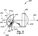
Projektionsmodul (100) eines Kraftfahrzeugscheinwerfers, das Modul (100) umfassend mindestens eine Halbleiterstrahlungsquelle (101) zum Aussenden von elektromagnetischer Strahlung, einen Reflektor (103) zum Reflektieren der ausgesandten Strahlung, eine Blendenanordnung (104) zum Abschatten zumindest eines Teils der reflektierten Strahlung und eine Projektionslinse (105), um die reflektierte und an der Blendenanordnung (104) vorbei gelangte Strahlung zur Erzeugung einer gewünschten Strahlungsverteilung mit einer Helldunkelgrenze aus dem Projektionsmodul (100) vor das Fahrzeug zu projizieren, wobei die mindestens eine Strahlungsquelle (101) auf oder nahe der Rückseite der Blendenanordnung (104) angeordnet und die Hauptabstrahlrichtung (111) der mindestens einen Strahlungsquelle (101) in den Halbraum entgegen der Strahlungsaustrittsrichtung (109) aus dem Projektionsmodul (100) gerichtet ist, wobei die mindestens eine Strahlungsquelle (101) mit einem Kühlkörper (107) wärmetechnisch in Verbindung steht, und wobei der Kühlkörper (107) integraler Bestandteil der Blendenanordnung (104) ist, dadurch gekennzeichnet, dass die Blendenanordnung (104) mehrere Blendenelemente aufweist, die zur Variation der Position und/oder des Verlaufs der Helldunkelgrenze der...Projection module (100) of a motor vehicle headlight, the module (100) comprising at least one semiconductor radiation source (101) for emitting electromagnetic radiation, a reflector (103) for reflecting the emitted radiation, a diaphragm arrangement (104) for shading at least a part of the reflected radiation and a projection lens (105) for projecting the reflected radiation past the aperture assembly (104) to the front of the vehicle to produce a desired radiation distribution with a light-dark boundary from the projection module (100), wherein the at least one radiation source (101) is at or near the rear side of the diaphragm arrangement (104) and the main radiation direction (111) of the at least one radiation source (101) in the half space against the radiation exit direction (109) from the projection module (100) is directed, wherein the at least one radiation source (101) with a heat sink (107) thermally in Wherein the heat sink (107) is an integral part of the diaphragm arrangement (104), characterized in that the diaphragm arrangement (104) has a plurality of diaphragm elements which are used to vary the position and / or the course of the light-dark boundary of the diaphragm.
Description
Die vorliegende Erfindung betrifft ein Projektionsmodul für einen Kraftfahrzeugscheinwerfer nach dem Oberbegriff des Anspruchs 1.The present invention relates to a projection module for a motor vehicle headlight according to the preamble of
Derartige Projektionsmodule mit einer oder mehreren LEDs (Light Emitting Diodes) als Strahlungsquelle sind in unterschiedlichen Ausführungsformen aus dem Stand der Technik bekannt. Je nach Wellenlänge der von der LED ausgesandten Strahlung kann das Projektionsmodul zum Aussenden von sichtbarem Licht oder von unsichtbarer Ultraviolett(UV)- oder Infrarot(IR)-Strahlung eingesetzt werden. Die unsichtbare Strahlung dient beispielsweise zur Ausleuchtung der Fahrbahn vor einem Kraftfahrzeug im Rahmen eines Nachtsichtgeräts (z. B. ”Night Vision” für Fahrzeuge von Mercedes-Benz oder BMW). Der mit der unsichtbaren Strahlung ausgeleuchtete Bereich kann mittels einer UV- oder IR-empfindlichen Kamera aufgenommen und dem Fahrer des Kraftfahrzeugs präsentiert werden, beispielsweise auf einem Bildschirm im Armaturenbrett oder durch Projektion auf die Innenseite der Windschutzscheibe.Such projection modules with one or more LEDs (light emitting diodes) as the radiation source are known in various embodiments from the prior art. Depending on the wavelength of the radiation emitted by the LED, the projection module can be used for emitting visible light or invisible ultraviolet (UV) or infrared (IR) radiation. The invisible radiation is used, for example, to illuminate the road ahead of a motor vehicle as part of a night vision device (eg "Night Vision" for vehicles from Mercedes-Benz or BMW). The area illuminated by the invisible radiation can be recorded by means of a UV or IR-sensitive camera and presented to the driver of the motor vehicle, for example on a screen in the dashboard or by projection onto the inside of the windscreen.
Bei den aus dem Stand der Technik bekannten LED-Projektionsmodulen sind die LEDs und die Blendenanordnung örtlich voneinander getrennt positioniert. Durch diesen Abstand zwischen den LEDs und der Blendenanordnung und durch den Abstand der Blendenanordnung zur Projektionslinse ist eine minimale Baulänge des Projektionssystems zwingend vorgegeben.In the case of the LED projection modules known from the prior art, the LEDs and the diaphragm arrangement are positioned separately from one another. Due to this distance between the LEDs and the diaphragm arrangement and the distance between the diaphragm arrangement and the projection lens, a minimum overall length of the projection system is mandatory.
Zukünftige Projektionsmodule müssen aufgrund steigender Komplexität der Kraftfahrzeugscheinwerfer, zusätzlicher Lichtfunktionen (z. B. Stadtlicht, Landstraßenlicht, Autobahnlicht, Schlechtwetterlicht, etc.), die in die Scheinwerfer integriert werden müssen, und neuer Designaspekte möglichst kompakt und kleinbauend ausgebildet sein. Bei LED-Lichtmodulen für Kraftfahrzeugscheinwerfer besteht zudem die Möglichkeit, mehrere LEDs bzw. LED-Arrays sowie unterschiedliche Systemarten (Projektion und Reflexion) in einem Leuchtmodul zu integrieren. Dies setzt allerdings ein möglichst kompaktes und kleinbauendes Lichtmodul voraus.Future projection modules must be designed to be as compact and small as possible due to increasing complexity of the motor vehicle headlights, additional lighting functions (eg city lights, country lights, motorway lights, bad weather light, etc.) that must be integrated into the headlights, and new design aspects. In the case of LED light modules for motor vehicle headlights, it is also possible to integrate several LEDs or LED arrays as well as different types of system (projection and reflection) in one light module. However, this requires a very compact and small-sized light module.
Aus der
Die bekannten Lichtmodule haben den Nachteil, dass sie lediglich zur Erzeugung einer abgeblendeten Lichtverteilung mit einem fest vorgegebenen Verlauf und einer fest vorgegebenen Position der Helldunkelgrenze ausgebildet sind. Die Realisierung einer adaptiven Lichtverteilung mit variabler Helldunkelgrenze ist mit den bekannten Lichtmodulen nicht möglich.The known light modules have the disadvantage that they are formed only to produce a dimmed light distribution with a fixed predetermined course and a fixed predetermined position of the light-dark boundary. The realization of an adaptive light distribution with a variable light-dark boundary is not possible with the known light modules.
Ausgehend von dem beschriebenen Stand der Technik liegt der vorliegenden Erfindung die Aufgabe zugrunde, ein Projektionsmodul für einen Kraftfahrzeugscheinwerfer der eingangs genannten Art dahingehend auszugestalten und weiterzubilden, dass es zur Realisierung einer adaptiven Lichtverteilung mit variabler Helldunkelgrenze geeignet ist.Based on the described prior art, the present invention has the object to design a further development of a projection module for a motor vehicle headlamp of the type mentioned and further, that it is suitable for the realization of an adaptive light distribution with variable light-dark boundary.
Zur Lösung dieser Aufgabe wird ein Projektionsmodul für einen Kraftfahrzeugscheinwerfer mit den Merkmalen des Anspruchs 1 vorgeschlagen. Insbesondere wird vorgeschlagen, dass die Blendenanordnung mehrere Blendenelemente aufweist, die zur Variation der Position und/oder des Verlaufs der Helldunkelgrenze der Strahlungsverteilung relativ zueinander verschwenkbar sind.To solve this problem, a projection module for a motor vehicle headlight with the features of
Durch die Anordnung der mindestens einen LED auf oder an der Rückseite der Blendenanordnung ist der Abstand zwischen den LEDs und der Blendenanordnung auf ein Minimum reduziert. Dadurch lässt sich die Bauraumlänge des Projektionsmoduls deutlich verringern, so dass die Einbautiefe eines Kraftfahrzeugscheinwerfers, der das erfindungsgemäße Projektionsmodul umfasst, verringert werden kann oder der im Scheinwerfergehäuse zur Verfügung stehende Bauraum anderweitig, beispielsweise für elektronische Steuerungs- und/oder Regelungsschaltungen oder für weitere Leuchtmodule genutzt werden kann.The arrangement of the at least one LED on or at the rear of the diaphragm arrangement, the distance between the LEDs and the diaphragm assembly is reduced to a minimum. As a result, the installation space length of the projection module can be significantly reduced, so that the installation depth of a motor vehicle headlight comprising the projection module according to the invention can be reduced or the space available in the headlight housing space otherwise, for example, used for electronic control and / or regulating circuits or for other lighting modules can be.
Das LED-Projektionsmodul verfügt über eine Blendenanordnung zum Abschatten eines Teils der von dem Reflektor reflektierten Strahlung. Damit eignet sich das Modul zur Erzeugung einer Lichtverteilung mit einer Helldunkelgrenze, bspw. einer Abblendlichtverteilung, einer Nebellichtverteilung, aber auch einer adaptiven Lichtverteilung umfassend bspw. Stadtlicht, Landstraßenlicht, Autobahnlicht, Schlechtwetterlicht, etc. Die Blendenanordnung kann bewegbar, insbesondere um eine horizontale, quer zur optischen Achse verlaufende Achse klappbar, ausgebildet sein, so dass sie aus dem Strahlengang heraus und in diesen hinein bewegt werden kann. Dadurch kann das Projektionsmodul zwischen Fernlicht und einer Lichtverteilung mit einer Helldunkelgrenze umgeschaltet werden. Zur Erzeugung der adaptiven Lichtverteilung weist die Blendenanordnung mehrere Blendenelemente auf, die relativ zueinander bewegbar, insbesondere um eine horizontale, parallel zur optischen Achse verlaufende Achse schwenkbar, ausgebildet sind. Der Verlauf der Helldunkelgrenze der Lichtverteilung wird durch die optisch wirksamen Oberkanten der oberen Blendenelemente bestimmt.The LED projection module has a diaphragm arrangement for shading a part of the radiation reflected by the reflector. Thus, the module is suitable for generating a light distribution with a light-dark boundary, for example a low-beam distribution, a fog light distribution, but also an adaptive light distribution comprising, for example, city lights, country lights, motorway lights, bad weather, etc. The diaphragm arrangement can be moved, in particular around a horizontal, transverse hinged to the optical axis extending axis, be formed so that it moves out of the beam path and into this can be. As a result, the projection module can be switched between high beam and a light distribution with a light-dark border. To produce the adaptive light distribution, the diaphragm arrangement has a plurality of diaphragm elements which are designed to be movable relative to one another, in particular pivotable about a horizontal axis extending parallel to the optical axis. The course of the light-dark boundary of the light distribution is determined by the optically effective upper edges of the upper diaphragm elements.
Erfindungsgemäß sind die LEDs in einer Ebene angeordnet, die im Wesentlichen der Erstreckungsebene der in dem Strahlengang angeordneten Blendenanordnung entspricht. Zudem sind die LEDs nach hinten, also in Fahrtrichtung rückwärts bzw. entgegen der Strahlungsaustrittsrichtung gerichtet. Vorzugsweise verläuft die Erstreckungsebene der Blendenanordnung schräg bzw. um eine horizontale, im Wesentlichen quer zur optischen Achse verlaufenden Achse geneigt, so dass die Hauptabstrahlrichtung der in der Erstreckungsebene angeordneten LEDs nicht parallel zur optischen Achse, sondern relativ zur optischen Achse nach oben geneigt verläuft.According to the invention, the LEDs are arranged in a plane which essentially corresponds to the plane of extent of the diaphragm arrangement arranged in the beam path. In addition, the LEDs are directed to the rear, ie in the direction of travel backwards or against the radiation exit direction. Preferably, the plane of extent of the diaphragm arrangement runs obliquely or inclined about a horizontal axis extending essentially transversely to the optical axis, so that the main emission direction of the LEDs arranged in the plane of extent does not run parallel to the optical axis but upwardly inclined relative to the optical axis.
Die mindestens eine Strahlungsquelle steht mit einem Kühlkörper wärmetechnisch in Verbindung. Auf den Kühlkörper übertragene Wärme von der Strahlungsquelle kann mittels Luftkühlung und/oder Flüssigkeitskühlung vom Kühlkörper abtransportiert werden. Die Größe des erfindungsgemäßen Projektionsmoduls kann dadurch weiter verringert werden, dass der Kühlkörper integraler Bestandteil der Blendenanordnung ist. Alternativ oder zusätzlich kann der Kühlkörper auch integraler Bestandteil einer Linsenhalterung sein, welche die Projektionslinse an dem Reflektor befestigt. Besonders vorteilhaft ist es, wenn der Kühlkörper derart ausgebildet ist, dass er einen Halterahmen des Projektionsmoduls ersetzt, welcher den Reflektor, die Blendenanordnung und die Projektionslinse in einem definierten Bezug relativ zueinander hält. Gemäß der vorliegenden Erfindung ist die Lichtquelle mit Befestigung und Kühlkörper in dem Raum zwischen Blendenanordnung bzw. der Erstreckungsebene der Blendenanordnung und Projektionslinse untergebracht.The at least one radiation source communicates with a heat sink in terms of heat technology. Heat transferred from the radiation source to the heat sink can be removed from the heat sink by means of air cooling and / or liquid cooling. The size of the projection module according to the invention can be further reduced by the fact that the heat sink is an integral part of the diaphragm arrangement. Alternatively or additionally, the heat sink may also be an integral part of a lens holder which fixes the projection lens to the reflector. It when the heat sink is designed such that it replaces a holding frame of the projection module, which holds the reflector, the diaphragm assembly and the projection lens in a defined relation relative to each other is particularly advantageous. According to the present invention, the light source with mounting and heat sink is accommodated in the space between the diaphragm arrangement and the plane of extension of the diaphragm arrangement and projection lens.
Nachfolgend wird eine bevorzugte Ausführungsform der vorliegenden Erfindung anhand der Figuren näher erläutert. Es zeigen:Hereinafter, a preferred embodiment of the present invention will be explained in more detail with reference to FIGS. Show it:
In
Das Projektionsmodul umfasst mindestens eine Lichtquelle
In
In
Bei den bekannten Projektionsmodulen
Erfindungsgemäß wird demgegenüber ein besonders kompaktes und kleinbauendes LED-Projektionsmodul vorgeschlagen, das in den
In
In
Anhand der Schnittdarstellung des erfindungsgemäßen LED-Projektionsmoduls
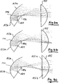
Wie in
Zur Vereinfachung kann die obere Reflektorhälfte
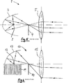
Die
Bei dem in
In
Claims (14)
Priority Applications (4)
| Application Number | Priority Date | Filing Date | Title |
|---|---|---|---|
| DE102007049309A DE102007049309B4 (en) | 2007-10-15 | 2007-10-15 | Projection module of a motor vehicle headlight |
| FR0804396A FR2922296B1 (en) | 2007-10-15 | 2008-08-01 | PROJECTION MODULE FOR A MOTOR VEHICLE HEADLIGHT. |
| JP2008213622A JP5468754B2 (en) | 2007-10-15 | 2008-08-22 | Projection module for automobile headlights |
| US12/200,047 US7963684B2 (en) | 2007-10-15 | 2008-08-28 | Semiconductor projection module having two-part reflector for an automobile headlamp |
Applications Claiming Priority (1)
| Application Number | Priority Date | Filing Date | Title |
|---|---|---|---|
| DE102007049309A DE102007049309B4 (en) | 2007-10-15 | 2007-10-15 | Projection module of a motor vehicle headlight |
Publications (2)
| Publication Number | Publication Date |
|---|---|
| DE102007049309A1 DE102007049309A1 (en) | 2009-04-16 |
| DE102007049309B4 true DE102007049309B4 (en) | 2013-04-11 |
Family
ID=40435511
Family Applications (1)
| Application Number | Title | Priority Date | Filing Date |
|---|---|---|---|
| DE102007049309A Active DE102007049309B4 (en) | 2007-10-15 | 2007-10-15 | Projection module of a motor vehicle headlight |
Country Status (4)
| Country | Link |
|---|---|
| US (1) | US7963684B2 (en) |
| JP (1) | JP5468754B2 (en) |
| DE (1) | DE102007049309B4 (en) |
| FR (1) | FR2922296B1 (en) |
Families Citing this family (36)
| Publication number | Priority date | Publication date | Assignee | Title |
|---|---|---|---|---|
| DE102009032455B4 (en) * | 2009-07-09 | 2020-07-09 | Automotive Lighting Reutlingen Gmbh | Projection module for a motor vehicle headlight with a projection lens, the axial position of which can be adjusted, and method for producing the projection module |
| JP2011040247A (en) * | 2009-08-10 | 2011-02-24 | Koito Mfg Co Ltd | Lamp unit of headlight for vehicle |
| JP5471596B2 (en) | 2010-03-01 | 2014-04-16 | 市光工業株式会社 | Vehicle lighting |
| FR2959973B1 (en) * | 2010-05-12 | 2013-03-22 | Valeo Vision | OPTICAL DEVICE, IN PARTICULAR FOR MOTOR VEHICLE |
| JP2011249184A (en) * | 2010-05-28 | 2011-12-08 | Koito Mfg Co Ltd | Headlamp for vehicle |
| EP2598797B1 (en) * | 2010-07-26 | 2021-01-20 | Valeo Vision | Optical module of an illuminating and/or signalling device of a motor vehicle |
| US9121561B2 (en) | 2010-07-26 | 2015-09-01 | Valeo Vision | Optical module of a lighting and/or signaling device for a motor vehicle |
| FR2964723B1 (en) * | 2010-09-09 | 2015-10-16 | Valeo Vision | OPTICAL MODULE FOR A LIGHTING AND / OR SIGNALING DEVICE FOR A MOTOR VEHICLE |
| FR2965039B1 (en) | 2010-07-26 | 2016-04-15 | Valeo Vision | OPTICAL MODULE FOR A LIGHTING AND / OR SIGNALING DEVICE FOR A MOTOR VEHICLE |
| CN102418906B (en) * | 2010-09-10 | 2014-10-15 | 株式会社小糸制作所 | Vehicle headlamp |
| US8905609B2 (en) | 2010-09-30 | 2014-12-09 | Osram Sylvania Inc. | Lighting system with shutter, reflector, primary light engine and a secondary light engine coupled to shutter |
| DE102010062465B4 (en) | 2010-12-06 | 2021-02-04 | Coretronic Corporation | Lighting device |
| JP5591097B2 (en) * | 2010-12-24 | 2014-09-17 | 株式会社小糸製作所 | Optical unit |
| DE102011003497B4 (en) * | 2011-02-02 | 2012-12-27 | Automotive Lighting Reutlingen Gmbh | Modular projection light module of a motor vehicle headlight |
| DE102011006699B4 (en) * | 2011-04-04 | 2021-05-27 | Osram Gmbh | Lighting device |
| DE102011077132A1 (en) | 2011-04-27 | 2012-01-12 | Automotive Lighting Reutlingen Gmbh | Light module for use in motor car headlamp for creating basic distribution of high beam light distribution, has blocking segment retrofitted to basic light distribution of high beam light distribution |
| DE102011077636A1 (en) | 2011-04-27 | 2011-11-03 | Automotive Lighting Reutlingen Gmbh | Light module for head lamp system of motor vehicle i.e. motor car, has sub modules separately controlled to generate set of strip-shaped segments of spot distribution, where strip-shaped segments are complement to spot distribution |
| DE102011082396A1 (en) * | 2011-09-09 | 2013-03-14 | Osram Ag | Lighting device has semiconductor light source, reflector optically downstream semiconductor light source, and screen optically downstream reflector, where semiconductor light source is fastened to screen |
| FR2982006B1 (en) * | 2011-09-13 | 2018-04-27 | Valeo Vision | OPTICAL MODULE WITH COMMON REFERENCE FOR LIGHTING AND / OR SIGNALING OF A MOTOR VEHICLE |
| JP5912539B2 (en) * | 2012-01-10 | 2016-04-27 | 株式会社小糸製作所 | Vehicle headlamp |
| DE102012202290B4 (en) * | 2012-02-15 | 2014-03-27 | Automotive Lighting Reutlingen Gmbh | Light module for a glare-free motor vehicle high beam |
| DE102012206397B4 (en) | 2012-04-18 | 2021-04-15 | Osram Gmbh | Lighting device with a screen, one side of which is irradiated by a first light source via a reflector and the other side, which is coated with a luminescent material, is irradiated by a second light source |
| FR3001027B1 (en) * | 2013-01-15 | 2015-03-20 | Valeo Vision | LIGHTING MODULE AND METHOD FOR MOUNTING SUCH A MODULE |
| JP6111805B2 (en) * | 2013-04-04 | 2017-04-12 | 市光工業株式会社 | Vehicle lighting |
| JP6244661B2 (en) * | 2013-05-24 | 2017-12-13 | 市光工業株式会社 | Vehicle lighting |
| FR3022975B1 (en) * | 2014-06-30 | 2020-06-19 | Valeo Vision | LIGHTING MODULE FOR AUTOMOTIVE PROJECTOR WITH POSITIONING BETWEEN FOLDER AND RADIATOR |
| WO2016024489A1 (en) * | 2014-08-11 | 2016-02-18 | 株式会社小糸製作所 | Vehicle headlight |
| DE102014216127A1 (en) * | 2014-08-13 | 2016-02-18 | Automotive Lighting Reutlingen Gmbh | Projection light module for a motor vehicle headlight with a central lens carrier |
| DE102015119513B4 (en) * | 2015-11-12 | 2021-10-21 | Dr. Ing. H.C. F. Porsche Aktiengesellschaft | Light for a motor vehicle |
| DE102016013510B4 (en) | 2016-04-18 | 2019-03-14 | Kastriot Merlaku | Headlight system for vehicles of all kinds, with at least one light source and a camera for the road detection |
| US10281104B2 (en) * | 2017-04-04 | 2019-05-07 | Chian Yih Optotech Co., Ltd. | Light-projecting device |
| WO2019214977A1 (en) * | 2018-05-08 | 2019-11-14 | Lumileds Holding B.V. | Headlamp for automotive vehicles |
| CN109812769B (en) * | 2019-02-18 | 2024-02-09 | 华域视觉科技(上海)有限公司 | LED car lamp and high beam module thereof |
| DE102019126263A1 (en) * | 2019-09-30 | 2021-04-01 | HELLA GmbH & Co. KGaA | Lighting device for vehicles |
| DE102021100999A1 (en) | 2021-01-19 | 2022-07-21 | HELLA GmbH & Co. KGaA | Light module with space-reduced cooling device, lighting system and motor vehicle |
| CN216047401U (en) * | 2021-08-31 | 2022-03-15 | 法雷奥照明湖北技术中心有限公司 | Car light module, motor vehicle head-light and motor vehicle |
Citations (7)
| Publication number | Priority date | Publication date | Assignee | Title |
|---|---|---|---|---|
| DE19832466A1 (en) * | 1998-07-18 | 2000-02-17 | Volkswagen Ag | Projection type headlamp assembly for a motor vehicle |
| EP1357332A2 (en) * | 2002-04-23 | 2003-10-29 | Koito Manufacturing Co., Ltd | Light source unit for vehicular lamp |
| DE102004017454A1 (en) * | 2003-04-08 | 2005-01-05 | Koito Mfg. Co., Ltd. | Headlights for vehicles |
| EP1526328A2 (en) * | 2003-10-24 | 2005-04-27 | Stanley Electric Co., Ltd. | Vehicle lamp |
| DE102005041065A1 (en) * | 2005-02-16 | 2006-08-24 | Patent-Treuhand-Gesellschaft für elektrische Glühlampen mbH | lighting device |
| EP1705422A1 (en) * | 2005-03-24 | 2006-09-27 | Ichikoh Industries, Ltd. | Vehicle lamp unit and vehicle headlamp using the same |
| US20070076422A1 (en) * | 2005-09-30 | 2007-04-05 | Valeo Vision | Lighting and/or signaling device for a motor vehicle incorporating a material having thermal anisotropy |
Family Cites Families (14)
| Publication number | Priority date | Publication date | Assignee | Title |
|---|---|---|---|---|
| US1397793A (en) * | 1921-01-10 | 1921-11-22 | Olin W Blackett | Headlight |
| US1702746A (en) * | 1926-05-26 | 1929-02-19 | Walter C Prichard | Automobile headlight |
| US1946379A (en) * | 1931-05-07 | 1934-02-06 | William A Ziesing | Vehicle light |
| DE3525041C2 (en) * | 1985-07-13 | 1994-06-16 | Bosch Gmbh Robert | Low beam or fog lights for motor vehicles |
| JPH07118208B2 (en) * | 1988-06-28 | 1995-12-18 | 株式会社小糸製作所 | Automotive headlights |
| US5264993A (en) * | 1990-01-30 | 1993-11-23 | Robert Bosch Gmbh | Headlamp for power vehicles |
| DE4002576C5 (en) * | 1990-01-30 | 2005-06-02 | Automotive Lighting Reutlingen Gmbh | Headlamp with dipped and main beam for motor vehicles |
| DE19756437A1 (en) * | 1997-12-18 | 1999-06-24 | Bosch Gmbh Robert | Vehicle headlamp with high and dipped beam settings |
| JP2001351408A (en) * | 2000-06-02 | 2001-12-21 | Stanley Electric Co Ltd | Lighting fixture for vehicle |
| DE10342635A1 (en) | 2003-09-16 | 2005-04-07 | Hella Kgaa Hueck & Co. | Vehicle headlight has light source with reflector lens and blind and a second navigation light between reflector and lens |
| FR2861831B1 (en) * | 2003-10-31 | 2006-01-20 | Valeo Vision | LIGHTING MODULE FOR VEHICLE PROJECTOR |
| JP4536479B2 (en) * | 2003-12-02 | 2010-09-01 | 株式会社小糸製作所 | Vehicle headlamp |
| JP2006127856A (en) * | 2004-10-27 | 2006-05-18 | Koito Mfg Co Ltd | Vehicular lighting lamp |
| FR2881509B1 (en) * | 2005-02-01 | 2007-03-16 | Valeo Vision Sa | VERTICALIZED PROJECTOR FOR MOTOR VEHICLE |
-
2007
- 2007-10-15 DE DE102007049309A patent/DE102007049309B4/en active Active
-
2008
- 2008-08-01 FR FR0804396A patent/FR2922296B1/en active Active
- 2008-08-22 JP JP2008213622A patent/JP5468754B2/en not_active Expired - Fee Related
- 2008-08-28 US US12/200,047 patent/US7963684B2/en not_active Expired - Fee Related
Patent Citations (7)
| Publication number | Priority date | Publication date | Assignee | Title |
|---|---|---|---|---|
| DE19832466A1 (en) * | 1998-07-18 | 2000-02-17 | Volkswagen Ag | Projection type headlamp assembly for a motor vehicle |
| EP1357332A2 (en) * | 2002-04-23 | 2003-10-29 | Koito Manufacturing Co., Ltd | Light source unit for vehicular lamp |
| DE102004017454A1 (en) * | 2003-04-08 | 2005-01-05 | Koito Mfg. Co., Ltd. | Headlights for vehicles |
| EP1526328A2 (en) * | 2003-10-24 | 2005-04-27 | Stanley Electric Co., Ltd. | Vehicle lamp |
| DE102005041065A1 (en) * | 2005-02-16 | 2006-08-24 | Patent-Treuhand-Gesellschaft für elektrische Glühlampen mbH | lighting device |
| EP1705422A1 (en) * | 2005-03-24 | 2006-09-27 | Ichikoh Industries, Ltd. | Vehicle lamp unit and vehicle headlamp using the same |
| US20070076422A1 (en) * | 2005-09-30 | 2007-04-05 | Valeo Vision | Lighting and/or signaling device for a motor vehicle incorporating a material having thermal anisotropy |
Also Published As
| Publication number | Publication date |
|---|---|
| JP2009099539A (en) | 2009-05-07 |
| US20090097269A1 (en) | 2009-04-16 |
| US7963684B2 (en) | 2011-06-21 |
| JP5468754B2 (en) | 2014-04-09 |
| DE102007049309A1 (en) | 2009-04-16 |
| FR2922296A1 (en) | 2009-04-17 |
| FR2922296B1 (en) | 2016-01-15 |
Similar Documents
| Publication | Publication Date | Title |
|---|---|---|
| DE102007049309B4 (en) | Projection module of a motor vehicle headlight | |
| EP2492580B1 (en) | Lighting device for installation in a motor vehicle | |
| EP2339228B1 (en) | Light module for a lighting device and lighting device of a motor vehicle with such a light module | |
| DE102007040728B4 (en) | vehicle headlights | |
| DE102008051109B4 (en) | Motor vehicle headlight and method for producing a motor vehicle headlight | |
| DE102007040760B4 (en) | Projection module of a vehicle headlight | |
| DE10101258B4 (en) | vehicle headlights | |
| DE60302708T2 (en) | Car headlights according to the projection principle with a secondary light source | |
| DE102007016294B4 (en) | vehicle light | |
| DE102014215785B4 (en) | Projection light module for a motor vehicle headlight | |
| DE102014200368B4 (en) | Partial remote light projection light module for a motor vehicle headlight | |
| DE102017206325A1 (en) | Vehicle lamp and vehicle with such | |
| DE102008015510A1 (en) | Luminaire unit of a vehicle headlight | |
| DE102009008631A1 (en) | Projection module for a motor vehicle headlight | |
| WO2006027230A1 (en) | Optical system for a motor vehicle headlight, illumination unit for a motor vehicle headlight and motor vehicle headlight | |
| DE102007021865A1 (en) | Lighting device for vehicle, especially motor vehicle, has cover frame with organic light emitting diodes visible from outside through cover panel and that emit light to implement at least some lighting functions when activated | |
| DE102009035743A1 (en) | Light module for a motor vehicle headlight | |
| DE19860669A1 (en) | Attenuating lighting close to vehicle while maintaining good overall output by using controllable partly reflecting and partly transparent plate in conjunction with complementary reflecting surface | |
| DE102009022848B4 (en) | Headlamp assembly and headlamp system for a motor vehicle | |
| DE10115868B4 (en) | Headlamp unit of a motor vehicle | |
| DE202010002800U1 (en) | Lighting device for a motor vehicle | |
| DE19839194B4 (en) | Headlamp for vehicles according to the projection principle | |
| EP3765781B1 (en) | Light module for motor vehicle headlight | |
| EP3625500B1 (en) | Lighting module of a motor vehicle headlight, and motor vehicle headlight comprising such a lighting module | |
| DE102011084890A1 (en) | Light module for illumination device e.g. headlight of motor car, has beam diaphragm that is arranged as integral portion of heatsink which is arranged indirectly and thermally in contact with semiconductor light source |
Legal Events
| Date | Code | Title | Description |
|---|---|---|---|
| 8110 | Request for examination paragraph 44 | ||
| R016 | Response to examination communication | ||
| R018 | Grant decision by examination section/examining division | ||
| R020 | Patent grant now final |
Effective date: 20130712 |
|
| R084 | Declaration of willingness to licence | ||
| R079 | Amendment of ipc main class |
Free format text: PREVIOUS MAIN CLASS: F21S0008120000 Ipc: F21S0041600000 |