JP5591097B2 - Optical unit - Google Patents
Optical unit Download PDFInfo
- Publication number
- JP5591097B2 JP5591097B2 JP2010287124A JP2010287124A JP5591097B2 JP 5591097 B2 JP5591097 B2 JP 5591097B2 JP 2010287124 A JP2010287124 A JP 2010287124A JP 2010287124 A JP2010287124 A JP 2010287124A JP 5591097 B2 JP5591097 B2 JP 5591097B2
- Authority
- JP
- Japan
- Prior art keywords
- focal point
- light emitting
- optical unit
- emitting element
- projection lens
- Prior art date
- Legal status (The legal status is an assumption and is not a legal conclusion. Google has not performed a legal analysis and makes no representation as to the accuracy of the status listed.)
- Expired - Fee Related
Links
Images


Description
本発明は、光学ユニットに関し、特に車両用灯具に用いられる光学ユニットに関する。 The present invention relates to an optical unit, and more particularly to an optical unit used for a vehicular lamp.
特許文献1には、半導体発光素子から照射された光をリフレクタで反射して、投影レンズを介して車両前方に照射する、車両用灯具用の光学ユニットが開示されている。この光学ユニットにおいて、リフレクタは略楕円球面状の反射面を有し、この反射面の第1焦点に半導体発光素子が配置され、第2焦点に投影レンズの後方焦点が配置されていた。そして、半導体発光素子から照射された光は、リフレクタの反射面で反射され、投影レンズの後方焦点を通過して投影レンズに入射して車両前方に照射されていた。
上述した従来の光学ユニットでは、半導体発光素子、および投影レンズの後方焦点は光学ユニットの光軸上に配置されていた。すなわち、リフレクタが有する反射面の第1焦点および第2焦点が光学ユニットの光軸上に配置されていた。そのため、従来の光学ユニットには光学ユニットの小型化を図る上で改善の余地があった。 In the conventional optical unit described above, the semiconductor light emitting element and the rear focal point of the projection lens are arranged on the optical axis of the optical unit. That is, the first focal point and the second focal point of the reflecting surface of the reflector are arranged on the optical axis of the optical unit. Therefore, the conventional optical unit has room for improvement in reducing the size of the optical unit.
本発明はこうした状況に鑑みてなされたものであり、その目的は、車両用灯具に用いられる光学ユニットを小型化する技術を提供することにある。 This invention is made | formed in view of such a condition, The objective is to provide the technique which miniaturizes the optical unit used for a vehicle lamp.
上記課題を解決するために、本発明のある態様は光学ユニットであり、当該光学ユニットは、発光素子の光を照射する車両用灯具に用いられる光学ユニットであって、発光素子搭載部と、略楕円面形状の反射面を有し、発光素子搭載部に固定された発光素子の光を反射するためのリフレクタと、リフレクタで反射された光を灯具前方に照射するための投影レンズと、を備え、反射面の第1焦点近傍に発光素子搭載部が位置し、反射面の第2焦点近傍に投影レンズの後方焦点が位置し、反射面の第1焦点の灯具前後方向位置が第2焦点と同一または第2焦点よりも前方にあることを特徴とする。 In order to solve the above-described problems, an aspect of the present invention is an optical unit, and the optical unit is an optical unit used in a vehicle lamp that irradiates light from a light-emitting element. A reflector having an elliptical reflecting surface and reflecting the light of the light emitting element fixed to the light emitting element mounting portion; and a projection lens for irradiating the light reflected by the reflector forward of the lamp. The light emitting element mounting portion is located near the first focal point of the reflecting surface, the rear focal point of the projection lens is located near the second focal point of the reflecting surface, and the lamp front-rear direction position of the first focal point of the reflecting surface is the second focal point. It is characterized by being in front of the same or second focus.
この態様によれば、光学ユニットの前後寸法を小さくすることができるため、光学ユニットを小型化することができる。 According to this aspect, since the front-rear dimension of the optical unit can be reduced, the optical unit can be reduced in size.
上記態様において、リフレクタは、発光素子の発光面から発光面の法線方向に照射された光を、投影レンズの前後方向に延びる中心軸を通るように反射してもよい。これによれば、発光素子から照射される光の光束利用率を高めることができる。 In the above aspect, the reflector may reflect the light emitted from the light emitting surface of the light emitting element in the normal direction of the light emitting surface so as to pass through the central axis extending in the front-rear direction of the projection lens. According to this, the luminous flux utilization factor of the light irradiated from the light emitting element can be increased.
上記態様において、光学ユニットを正面から見て、反射面の第1焦点が投影レンズと重なっていてもよい。これによれば、光学ユニットの上下寸法を小さくすることができるため、光学ユニットをさらに小型化することができる。 In the above aspect, the first focal point of the reflecting surface may overlap the projection lens when the optical unit is viewed from the front. According to this, since the vertical dimension of the optical unit can be reduced, the optical unit can be further downsized.
本発明によれば、車両用灯具に用いられる光学ユニットを小型化する技術を提供することができる。 ADVANTAGE OF THE INVENTION According to this invention, the technique which miniaturizes the optical unit used for a vehicle lamp can be provided.
以下、本発明を好適な実施の形態をもとに図面を参照しながら説明する。各図面に示される同一または同等の構成要素、部材、処理には、同一の符号を付するものとし、適宜重複した説明は省略する。また、実施の形態は、発明を限定するものではなく例示であって、実施の形態に記述されるすべての特徴やその組み合わせは、必ずしも発明の本質的なものであるとは限らない。 The present invention will be described below based on preferred embodiments with reference to the drawings. The same or equivalent components, members, and processes shown in the drawings are denoted by the same reference numerals, and repeated descriptions are omitted as appropriate. The embodiments do not limit the invention but are exemplifications, and all features and combinations thereof described in the embodiments are not necessarily essential to the invention.
(実施形態1)
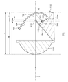
図1は、実施形態1に係る光学ユニットを備えた車両用灯具の概略鉛直断面図である。本実施形態に係る車両用灯具1は、車両前方の左右に配置される一対の前照灯ユニットを有する車両用前照灯装置である。一対の前照灯ユニットは左右対称の構造を有する点以外は実質的に同一の構成であるため、図1には車両用灯具1として一方の前照灯ユニットの構造を示す。
(Embodiment 1)
FIG. 1 is a schematic vertical sectional view of a vehicular lamp including the optical unit according to the first embodiment. The
図1に示すように、本実施形態に係る車両用灯具1は、車両前方側に開口部を有するランプボディ2と、ランプボディ2の開口部を覆うように取り付けられた透光カバー4とを備える。透光カバー4は、透光性を有する樹脂やガラス等で形成されている。ランプボディ2と透光カバー4とにより形成される灯室3内には、光学ユニット100が収容されている。
As shown in FIG. 1, the
光学ユニット100は、いわゆるプロジェクタ型の光学ユニットであり、ヒートシンク110、リフレクタ130、および投影レンズ150を備える。また、光学ユニット100は、ロービーム用配光パターンを形成するための光学ユニットである。光学ユニット100は、その光軸Xが車両前後方向に延びるように配置されてランプボディ2に連結されている。本実施形態では光学ユニット100の前後方向と車両前後方向とは一致している。
The
ヒートシンク110は、光源としての発光素子が搭載される部材であるとともに、リフレクタ130および投影レンズ150を支持する部材として機能する。ヒートシンク110は、背面部112、および発光素子搭載部114を有する。
The
背面部112は、略平板状であり、その主表面が灯具前後方向を向くように配置されている。背面部112の上部には螺孔が設けられており、ランプボディ2の壁面に回転自在に支持されたエイミングスクリュー6がこの螺孔に螺合している。また、背面部112の下部にはジョイント受け部116が灯具後方に突出するように設けられており、ランプボディ2の壁面を貫通して灯具前方に延出するレベリングシャフト8がジョイント受け部116に連結されている。レベリングシャフト8の先端にはボールジョイント用球部8aが形成され、ジョイント受け部116にはボールジョイント用球部8aの形状に沿った球形空間が形成されている。ジョイント受け部116とレベリングシャフト8は、ボールジョイント用球部8aがジョイント受け部116の球形空間に収容されることで連結される。また、レベリングシャフト8は、レベリングアクチュエータ10に接続されている。車両用灯具1は、エイミングスクリュー6と、レベリングシャフト8およびレベリングアクチュエータ10とにより、光学ユニット100の光軸Xを上下左右に調整可能である。
The
発光素子搭載部114は、背面部112の灯具前方を向く主表面から灯具前方に延びている。発光素子搭載部114は、発光素子搭載面114aを有し、発光素子搭載面114aに発光素子202を有する光源モジュール200が固定されている。ヒートシンク110は、例えばアルミダイキャスト製であり、背面部112、および発光素子搭載部114が一体成形されている。
The light emitting
光源モジュール200は、例えば発光ダイオード(LED)であり、発光素子202と、発光素子202を支持する基板204とを有する。基板204は、セラミックなどで形成された熱伝導性絶縁基板である。基板204には、発光素子202に電力を伝達する電極(図示せず)が形成されている。
The
リフレクタ130は、発光素子搭載部114に固定された発光素子202の光を反射するための部材である。リフレクタ130はドーム状であり、発光素子202の持つ発光面の上方を覆うようにして発光素子搭載部114に固定されている。リフレクタ130は、発光素子202から照射された光を反射するための第1反射面132および第2反射面134が内側に形成されている。第1反射面132は、光軸Xを中心軸とする回転楕円面の一部で構成されている。すなわち、第1反射面132は略楕円面形状の反射面である。第1反射面132は、リフレクタ130の発光素子202側の端部から所定の領域にかけて延在している。第2反射面134は、所定の形状を有し、第1反射面132の前端部(発光素子202側と反対側の端部)からリフレクタ130の投影レンズ150側の端部にかけて延在している。リフレクタ130は、第1反射面132の第1焦点F1の近傍に発光素子搭載部114が位置し(したがって第1焦点F1の近傍に発光素子202が位置し)、第1反射面132の第2焦点F2の近傍に投影レンズ150の後方焦点Fが位置するようにして、投影レンズ150よりも灯具後方側に配置されている。
The
投影レンズ150は、リフレクタ130で反射された光を灯具前方に照射するためのレンズであり、前方側表面が凸面で後方側表面が平面の平凸非球面レンズからなる。投影レンズ150は、その後方焦点Fを含む後方焦点面上に形成される光源像を、反転像として灯具前方の仮想鉛直スクリーン上に投影する。投影レンズ150は、その周縁部が発光素子搭載部114に固定されて光軸X上に設けられている。投影レンズ150の後方焦点Fは、第1反射面132の第2焦点F2の近傍に配置されている。
The
また、光学ユニット100は、シェード170を有する。シェード170は、略平板状であり、その一辺の先端部(稜線)が第1反射面132の第2焦点F2、および投影レンズ150の後方焦点Fの近傍に位置するようにして、発光素子搭載部114に固定されている。第2焦点F2および後方焦点Fの近傍に位置する先端部は、ロービーム用配光パターンのカットオフラインに対応した形状を有する。
The
発光素子202から照射された光の一部は、リフレクタ130の第1反射面132により投影レンズ150の後方焦点Fに向けて反射される。後方焦点Fに向かった光は、その一部がシェード170により選択的にカットされて、残りが投影レンズ150に入射する。後方焦点Fを通って投影レンズ150に入射したこの光は、後述するロービーム用配光パターンのカットオフラインを形成するためのカットオフライン形成光Aとして投影レンズ150から灯具前方に照射される。また、発光素子202から照射された光の他の一部は、第2反射面134で反射されて後方焦点Fの上方を通過して投影レンズ150に入射する。後方焦点Fの上方を通過して投影レンズ150に入射したこの光は、投影レンズ150からロービーム用配光パターンの拡散部を形成するための拡散部形成光Bとして灯具前方に照射される。また、発光素子202から照射された光のさらに他の一部は、第1反射面132により第2反射面134に向けて反射され、第2反射面134でさらに反射されて後方焦点Fの上方を通過して投影レンズ150に入射する。第1反射面132と第2反射面134とで2回反射して投影レンズ150に入射したこの光は、投影レンズ150から拡散部形成光Bとして灯具前方に照射される。拡散部形成光Bは、カットオフライン形成光Aよりも下向きの光として投影レンズ150から照射される。
Part of the light emitted from the
上述のように構成された光学ユニット100で形成される配光パターンについて説明する。図2は、実施形態1に係る光学ユニットで形成される配光パターンの模式図である。なお、図2では、灯具前方の所定位置、例えば灯具前方25mの位置に配置された仮想鉛直スクリーン上に形成された配光パターンを示している。
A light distribution pattern formed by the
図2に示すように、光学ユニット100によりロービーム用配光パターンPLが形成される。このロービーム用配光パターンPLは、左側通行時に前方車両や歩行者にグレアを与えないように配慮された配光パターンである。ロービーム用配光パターンPLは、その上端の鉛直ラインVよりも右側に、水平ラインHと平行に延びる対向車線側カットオフラインCL1を有する。また、ロービーム用配光パターンPLは、鉛直ラインVよりも左側に、対向車線側カットオフラインCL1よりも高い位置で水平ラインHと平行に延びる自車線側カットオフラインCL2を有する。さらに、ロービーム用配光パターンPLは、対向車線側カットオフラインCL1と自車線側カットオフラインCL2との間に、両者をつなぐ斜めカットオフラインCL3を有する。斜めカットオフラインCL3は、自車線側カットオフラインCL2の鉛直ラインV側の端部から左斜め上方へ45°の傾斜角で延びている。対向車線側カットオフラインCL1、自車線側カットオフラインCL2、および斜めカットオフラインCL3は、シェード170の前述した先端部によって作り出されるラインである。また、ロービーム用配光パターンPLは、各カットオフラインの下方に拡がる拡散部PDを有する。
As shown in FIG. 2, a low beam light distribution pattern PL is formed by the
ロービーム用配光パターンPLの対向車線側カットオフラインCL1、自車線側カットオフラインCL2、および斜めカットオフラインCL3は、光学ユニット100から照射されるカットオフライン形成光Aによって形成される。また、ロービーム用配光パターンPLの拡散部PDは、光学ユニット100から照射される拡散部形成光Bによって形成される。
The opposite lane side cut-off line CL1, the own lane side cut-off line CL2, and the oblique cut-off line CL3 of the low beam light distribution pattern PL are formed by the cut-off line forming light A emitted from the
続いて、本実施形態に係る光学ユニット100について詳細に説明する。図3は、比較例に係る光学ユニットの概略鉛直断面図である。図4は、実施形態1に係る光学ユニットの概略鉛直断面図である。なお、図3、および図4では、ヒートシンクの背面部を省略している。
Next, the
図3に示すように、比較例に係る光学ユニット300は、ヒートシンク310、リフレクタ330、および投影レンズ350を有する。ヒートシンク310は、灯具前後方向に延びる発光素子搭載部314を有する。発光素子搭載部314は、鉛直方向上方を向く発光素子搭載面314aを有する。光源モジュール200は、発光素子202の発光面の法線が鉛直方向に延びるようにして発光素子搭載面314aに固定されている。リフレクタ330は、略楕円面形状の反射面332を有する。リフレクタ330は、反射面332の第1焦点F1の近傍に発光素子搭載部314が位置し(したがって、第1焦点F1近傍に発光素子202が位置し)、第2焦点F2の近傍に投影レンズ350の後方焦点Fが位置するようにして、投影レンズ350よりも灯具後方側に配置されている。
As illustrated in FIG. 3, the
比較例に係る光学ユニット300において、発光素子202、および投影レンズ350の後方焦点Fは、光学ユニット300の光軸X上に配置されている。すなわち、反射面332の第1焦点F1および第2焦点F2が光軸X上に配置されている。そして、第1焦点F1が第2焦点F2より灯具後方側に位置している。したがって、光学ユニット300の灯具前後方向の寸法(前後寸法)に影響する投影レンズ350の前端からリフレクタ330の後端までの灯具前後方向の長さLは、投影レンズ350の前端から後方焦点Fまでの長さMと、後方焦点Fと略一致する第2焦点F2から第1焦点F1までの長さである焦点間距離Nと、第1焦点F1からリフレクタ330の後端までの長さOとの合計となる。
In the
これに対し、本実施形態に係る光学ユニット100では、発光素子搭載部114の発光素子搭載面114aが灯具後方側に傾斜している。そのため、光源モジュール200は、発光素子202の持つ発光面の法線が鉛直方向よりも灯具後方に傾いている。そして、第1反射面132の第1焦点F1は、その灯具前後方向位置が第2焦点F2よりも前方に位置している。すなわち、発光素子202が投影レンズ150の後方焦点Fよりも灯具前方側に配置されている。したがって、投影レンズ150の前端からリフレクタ130の後端までの長さLは、投影レンズ150の前端から後方焦点Fまでの長さMと、後方焦点Fと略一致する第2焦点F2からリフレクタ130の後端までの長さPとの合計となる。なお、リフレクタ130の後端に位置する部分は、内側に第1反射面132が形成された部分である。
On the other hand, in the
投影レンズの前端から後方焦点Fまでの長さMは、投影レンズの大きさや形状に応じて決まるため、後方焦点Fからリフレクタ後端までの長さが光学ユニット100の前後寸法を決定するといえる。焦点距離Nを固定して後方焦点Fからリフレクタ後端までの長さを変化させようとする場合、第2焦点F2を中心に第1焦点F1が回動することになる。したがって第1焦点F1および第2焦点F2を焦点とする楕円が第2焦点F2を中心に回動することになる。このとき、比較例のように第1焦点F1が第2焦点F2より灯具後方側に位置する場合は、後方焦点Fからリフレクタ後端までの長さは焦点間距離Nと第1焦点F1からリフレクタ後端までの距離Oとの合計となる。一方、本実施形態のように第1焦点F1が第2焦点F2より灯具前方側に位置する場合、あるいは第1焦点F1と第2焦点F2の灯具前後方向位置が同じ場合は、後方焦点Fからリフレクタ後端までの長さは第2焦点F2からリフレクタ後端までの距離Pとなる。
Since the length M from the front end of the projection lens to the rear focal point F is determined according to the size and shape of the projection lens, it can be said that the length from the rear focal point F to the rear end of the reflector determines the longitudinal dimension of the
ここで、楕円は短軸に対して線対称である。そのため、第1焦点F1および第2焦点F2が鉛直方向に並んだ状態、すなわち楕円の長軸が鉛直方向に延びる状態を基準として、そこから第1焦点F1が灯具後方に変位するように所定角度だけ長軸を傾けたときの第1焦点F1からリフレクタ後端までの長さOと、第1焦点F1が灯具前方に変位するように同じ角度だけ長軸を傾けたときの第2焦点F2からリフレクタ後端までの長さPは等しい。したがって、第1焦点F1の灯具前後方向位置が第2焦点F2と同一または第2焦点F2より前方にある場合は、焦点間距離Nの分だけ後方焦点Fからリフレクタ後端までの長さを短くすることができる。これにより、光学ユニット100の前後寸法(奥行き寸法)を小さくすることができるため、光学ユニット100を小型化することができる。
Here, the ellipse is line symmetric with respect to the short axis. Therefore, with the first focal point F1 and the second focal point F2 aligned in the vertical direction, that is, the state in which the major axis of the ellipse extends in the vertical direction, a predetermined angle is set so that the first focal point F1 is displaced backward from the lamp. From the first focal point F1 when the major axis is tilted to the rear end of the reflector, and from the second focal point F2 when the major axis is tilted by the same angle so that the first focal point F1 is displaced forward of the lamp The length P to the rear end of the reflector is equal. Therefore, when the position of the first focal point F1 in the longitudinal direction of the lamp is the same as that of the second focal point F2 or in front of the second focal point F2, the length from the rear focal point F to the rear end of the reflector is shortened by the distance N between the focal points. can do. Thereby, since the front-back dimension (depth dimension) of the
また、本実施形態に係る光学ユニット100において、リフレクタ130は、発光素子202の発光面から発光面の法線方向に照射された光Dを、投影レンズ150の前後方向に延びる中心軸を通るように反射する。発光素子202は、発光面の法線方向が最も光度が高い指向特性を有するため、法線方向に照射された光Dを投影レンズ150の中心に入射させることで、発光素子202の照射光の光束利用率を高めることができる。なお、本実施形態に係る光学ユニット100では、投影レンズ150の前後方向に延びる中心軸は、光軸Xと一致している。
In the
また、図4に示すように、第1反射面132の第1焦点F1は、投影レンズ150の外周縁よりも光軸X寄りに位置している。したがって、光学ユニット100を正面から見た場合、第1反射面132の第1焦点F1が投影レンズ150と重なることになる。これにより、光学ユニット100の上下寸法を小さくすることができるため、光学ユニット100をさらに小型化することができる。あるいは、これにより、第1焦点F1の灯具前後方向位置を第2焦点F2と同一か第2焦点F2より前方にしたことによる光学ユニット100の上下寸法の大型化を回避できる。また、発光素子搭載部114は、発光素子202から照射された光が通過する領域の外側に位置している。そのため、発光素子搭載部114は、光学ユニット100によるロービーム用配光パターンPLの形成を妨げない。
As shown in FIG. 4, the first focal point F <b> 1 of the first reflecting
なお、前記「第1焦点F1の近傍」、「第2焦点F2の近傍」、および「後方焦点Fの近傍」は、それぞれの焦点位置と、それぞれの焦点に近く上述した配光パターンの形成が可能な領域、例えば、光学ユニット製造時の組み付け誤差範囲の領域とを含む。また、前記「略平板状」、および「略楕円面形状」は、それぞれの形状と、それぞれの形状に近い形状、例えば、製造時の寸法誤差を有する形状とを含む。また、「略楕円面形状」は、楕円面を基本として複数のステップが形成された形状を含む。 The “near first focus F1,” “near second focus F2,” and “near rear focus F” are the positions of the respective focal points and the light distribution patterns described above that are close to the respective focal points. This includes a possible area, for example, an assembling error range area when the optical unit is manufactured. The “substantially flat plate shape” and “substantially elliptic surface shape” include each shape and a shape close to each shape, for example, a shape having a dimensional error during manufacturing. The “substantially elliptical shape” includes a shape in which a plurality of steps are formed based on the elliptical surface.
以上説明したように、本実施形態に係る光学ユニット100は、発光素子202の光を照射する車両用灯具1に用いられる光学ユニットであって、略楕円面形状の第1反射面132を有するリフレクタ130を備える。そして、第1反射面132の第1焦点F1近傍に発光素子搭載部114が配置され、第2焦点F2近傍に投影レンズ150の後方焦点Fが配置され、第1焦点F1の灯具前後方向位置が第2焦点F2と同一または第2焦点F2よりも前方に設定されている。これにより、第1焦点F1の灯具前後方向位置が第2焦点F2よりも後方に設定された構成に比べて、光学ユニット100の前後寸法を小さくすることができるため、光学ユニット100を小型化することができる。また、これにより、車両用灯具1の小型化を図ることができる。
As described above, the
本発明は、上述の実施形態に限定されるものではなく、当業者の知識に基づいて各種の設計変更等の変形を加えることが可能であり、そのような変形が加えられた実施形態も本発明の範囲に含まれる。上述の実施形態に変形が加えられた新たな実施形態は、組み合わされる実施形態および変形それぞれの効果をあわせもつ。 The present invention is not limited to the above-described embodiments, and various modifications such as design changes can be added based on the knowledge of those skilled in the art, and the embodiments to which such modifications are added are also described in the present invention. It is included in the scope of the invention. A new embodiment in which a modification is added to the above-described embodiment has the effects of the combined embodiment and the modification.
1 車両用灯具、 100 光学ユニット、 114 発光素子搭載部、 130 リフレクタ、 132 第1反射面、 134 第2反射面、 150 投影レンズ、 202 発光素子、 F 後方焦点、 F1 第1焦点、 F2 第2焦点。
DESCRIPTION OF
Claims (3)
発光素子搭載部と、
略楕円面形状の反射面を有し、前記発光素子搭載部に固定された発光素子の光を反射するためのリフレクタと、
前記リフレクタで反射された光を灯具前方に照射するための投影レンズと、を備え、
前記反射面の第1焦点近傍に前記発光素子搭載部が位置し、前記反射面の第2焦点近傍に前記投影レンズの後方焦点が位置し、前記反射面の第1焦点の灯具前後方向位置が第2焦点と同一または第2焦点よりも前方にあることを特徴とする光学ユニット。 An optical unit used in a vehicular lamp that emits light from a light emitting element,
A light emitting element mounting portion;
A reflector for reflecting the light of the light emitting element, which has a substantially elliptical reflecting surface and is fixed to the light emitting element mounting portion;
A projection lens for irradiating the light reflected by the reflector in front of the lamp, and
The light emitting element mounting portion is located near the first focal point of the reflecting surface, the rear focal point of the projection lens is located near the second focal point of the reflecting surface, and the lamp front-rear direction position of the first focal point of the reflecting surface is An optical unit that is the same as or in front of the second focal point.
Priority Applications (1)
| Application Number | Priority Date | Filing Date | Title |
|---|---|---|---|
| JP2010287124A JP5591097B2 (en) | 2010-12-24 | 2010-12-24 | Optical unit |
Applications Claiming Priority (1)
| Application Number | Priority Date | Filing Date | Title |
|---|---|---|---|
| JP2010287124A JP5591097B2 (en) | 2010-12-24 | 2010-12-24 | Optical unit |
Publications (2)
| Publication Number | Publication Date |
|---|---|
| JP2012134091A JP2012134091A (en) | 2012-07-12 |
| JP5591097B2 true JP5591097B2 (en) | 2014-09-17 |
Family
ID=46649439
Family Applications (1)
| Application Number | Title | Priority Date | Filing Date |
|---|---|---|---|
| JP2010287124A Expired - Fee Related JP5591097B2 (en) | 2010-12-24 | 2010-12-24 | Optical unit |
Country Status (1)
| Country | Link |
|---|---|
| JP (1) | JP5591097B2 (en) |
Families Citing this family (3)
| Publication number | Priority date | Publication date | Assignee | Title |
|---|---|---|---|---|
| CN109282234A (en) * | 2018-10-15 | 2019-01-29 | 华域视觉科技(上海)有限公司 | A kind of automobile dipped headlight projecting unit and its car light |
| WO2021193702A1 (en) | 2020-03-27 | 2021-09-30 | 株式会社小糸製作所 | Vehicle lamp system, light distribution control device, light distribution control method, vehicle determination device, and vehicle determination method |
| EP4265477A4 (en) | 2020-12-15 | 2024-03-27 | Koito Mfg Co Ltd | Vehicle light fixture system, light distribution control device, and light distribution control method |
Family Cites Families (3)
| Publication number | Priority date | Publication date | Assignee | Title |
|---|---|---|---|---|
| JP2006127856A (en) * | 2004-10-27 | 2006-05-18 | Koito Mfg Co Ltd | Vehicular lighting lamp |
| JP4863502B2 (en) * | 2007-05-21 | 2012-01-25 | スタンレー電気株式会社 | Vehicle headlamp |
| DE102007049309B4 (en) * | 2007-10-15 | 2013-04-11 | Automotive Lighting Reutlingen Gmbh | Projection module of a motor vehicle headlight |
-
2010
- 2010-12-24 JP JP2010287124A patent/JP5591097B2/en not_active Expired - Fee Related
Also Published As
| Publication number | Publication date |
|---|---|
| JP2012134091A (en) | 2012-07-12 |
Similar Documents
| Publication | Publication Date | Title |
|---|---|---|
| JP5652996B2 (en) | Vehicle lighting | |
| US7607811B2 (en) | Lighting unit | |
| JP4089866B2 (en) | Light projecting unit and LED vehicle illumination lamp comprising the light projecting unit | |
| JP5281359B2 (en) | Vehicle lamp unit and vehicle lamp | |
| JP5257665B2 (en) | Vehicle headlight unit and vehicle headlight | |
| JP6516495B2 (en) | Vehicle lamp | |
| US8678629B2 (en) | Lamp unit for vehicular headlamp | |
| JP2005294176A (en) | Lighting lamp for vehicle | |
| JP2010055888A (en) | Vehicular lamp unit | |
| JP2007324042A (en) | Vehicle light | |
| JP2011165600A (en) | Vehicular illumination lamp | |
| JP2008041557A (en) | Lamp unit for vehicle headlight | |
| JP2005190668A (en) | Vehicular lamp unit | |
| JP2012156051A (en) | Vehicle headlamp | |
| JP5847105B2 (en) | Vehicle lighting | |
| JP5326821B2 (en) | Lighting fixtures for vehicles | |
| JP6030864B2 (en) | Lamp unit and projection lens | |
| JP4809635B2 (en) | Vehicle headlamp | |
| JP5711558B2 (en) | Optical unit and vehicle lamp | |
| JP2008288113A (en) | Vehicle headlamp | |
| JP5332070B2 (en) | Vehicle headlight unit and vehicle headlight | |
| JP5365163B2 (en) | Vehicle lighting | |
| JP2016058347A (en) | Lamp unit | |
| JP5591097B2 (en) | Optical unit | |
| JP5468876B2 (en) | Optical unit |
Legal Events
| Date | Code | Title | Description |
|---|---|---|---|
| A621 | Written request for application examination |
Free format text: JAPANESE INTERMEDIATE CODE: A621 Effective date: 20131106 |
|
| A977 | Report on retrieval |
Free format text: JAPANESE INTERMEDIATE CODE: A971007 Effective date: 20140625 |
|
| TRDD | Decision of grant or rejection written | ||
| A01 | Written decision to grant a patent or to grant a registration (utility model) |
Free format text: JAPANESE INTERMEDIATE CODE: A01 Effective date: 20140722 |
|
| A61 | First payment of annual fees (during grant procedure) |
Free format text: JAPANESE INTERMEDIATE CODE: A61 Effective date: 20140729 |
|
| R150 | Certificate of patent or registration of utility model |
Ref document number: 5591097 Country of ref document: JP Free format text: JAPANESE INTERMEDIATE CODE: R150 |
|
| LAPS | Cancellation because of no payment of annual fees |