CN100559058C - Vehicle head lamp - Google Patents
Vehicle head lamp Download PDFInfo
- Publication number
- CN100559058C CN100559058C CNB2004100809614A CN200410080961A CN100559058C CN 100559058 C CN100559058 C CN 100559058C CN B2004100809614 A CNB2004100809614 A CN B2004100809614A CN 200410080961 A CN200410080961 A CN 200410080961A CN 100559058 C CN100559058 C CN 100559058C
- Authority
- CN
- China
- Prior art keywords
- light source
- light
- source module
- vehicle head
- luminous intensity
- Prior art date
- Legal status (The legal status is an assumption and is not a legal conclusion. Google has not performed a legal analysis and makes no representation as to the accuracy of the status listed.)
- Expired - Fee Related
Links
- 230000003287 optical effect Effects 0.000 claims abstract description 90
- 238000005286 illumination Methods 0.000 claims abstract description 11
- 238000009792 diffusion process Methods 0.000 claims description 34
- 230000015572 biosynthetic process Effects 0.000 claims description 32
- 238000004806 packaging method and process Methods 0.000 claims description 8
- 230000003760 hair shine Effects 0.000 claims description 5
- 241000278713 Theora Species 0.000 claims description 2
- 229910052736 halogen Inorganic materials 0.000 description 8
- 150000002367 halogens Chemical class 0.000 description 8
- 230000000903 blocking effect Effects 0.000 description 5
- 238000010586 diagram Methods 0.000 description 5
- 238000005457 optimization Methods 0.000 description 5
- 238000012797 qualification Methods 0.000 description 2
- 230000005855 radiation Effects 0.000 description 2
- 230000003321 amplification Effects 0.000 description 1
- 230000000694 effects Effects 0.000 description 1
- 238000005516 engineering process Methods 0.000 description 1
- 238000003199 nucleic acid amplification method Methods 0.000 description 1
- 230000000149 penetrating effect Effects 0.000 description 1
- 239000011347 resin Substances 0.000 description 1
- 229920005989 resin Polymers 0.000 description 1
- 239000000758 substrate Substances 0.000 description 1
- 238000013316 zoning Methods 0.000 description 1
Images


Classifications
-
- F—MECHANICAL ENGINEERING; LIGHTING; HEATING; WEAPONS; BLASTING
- F21—LIGHTING
- F21S—NON-PORTABLE LIGHTING DEVICES; SYSTEMS THEREOF; VEHICLE LIGHTING DEVICES SPECIALLY ADAPTED FOR VEHICLE EXTERIORS
- F21S41/00—Illuminating devices specially adapted for vehicle exteriors, e.g. headlamps
- F21S41/40—Illuminating devices specially adapted for vehicle exteriors, e.g. headlamps characterised by screens, non-reflecting members, light-shielding members or fixed shades
- F21S41/43—Illuminating devices specially adapted for vehicle exteriors, e.g. headlamps characterised by screens, non-reflecting members, light-shielding members or fixed shades characterised by the shape thereof
-
- F—MECHANICAL ENGINEERING; LIGHTING; HEATING; WEAPONS; BLASTING
- F21—LIGHTING
- F21S—NON-PORTABLE LIGHTING DEVICES; SYSTEMS THEREOF; VEHICLE LIGHTING DEVICES SPECIALLY ADAPTED FOR VEHICLE EXTERIORS
- F21S41/00—Illuminating devices specially adapted for vehicle exteriors, e.g. headlamps
- F21S41/10—Illuminating devices specially adapted for vehicle exteriors, e.g. headlamps characterised by the light source
- F21S41/14—Illuminating devices specially adapted for vehicle exteriors, e.g. headlamps characterised by the light source characterised by the type of light source
- F21S41/141—Light emitting diodes [LED]
- F21S41/143—Light emitting diodes [LED] the main emission direction of the LED being parallel to the optical axis of the illuminating device
-
- F—MECHANICAL ENGINEERING; LIGHTING; HEATING; WEAPONS; BLASTING
- F21—LIGHTING
- F21S—NON-PORTABLE LIGHTING DEVICES; SYSTEMS THEREOF; VEHICLE LIGHTING DEVICES SPECIALLY ADAPTED FOR VEHICLE EXTERIORS
- F21S41/00—Illuminating devices specially adapted for vehicle exteriors, e.g. headlamps
- F21S41/10—Illuminating devices specially adapted for vehicle exteriors, e.g. headlamps characterised by the light source
- F21S41/14—Illuminating devices specially adapted for vehicle exteriors, e.g. headlamps characterised by the light source characterised by the type of light source
- F21S41/141—Light emitting diodes [LED]
- F21S41/147—Light emitting diodes [LED] the main emission direction of the LED being angled to the optical axis of the illuminating device
- F21S41/148—Light emitting diodes [LED] the main emission direction of the LED being angled to the optical axis of the illuminating device the main emission direction of the LED being perpendicular to the optical axis
-
- F—MECHANICAL ENGINEERING; LIGHTING; HEATING; WEAPONS; BLASTING
- F21—LIGHTING
- F21S—NON-PORTABLE LIGHTING DEVICES; SYSTEMS THEREOF; VEHICLE LIGHTING DEVICES SPECIALLY ADAPTED FOR VEHICLE EXTERIORS
- F21S41/00—Illuminating devices specially adapted for vehicle exteriors, e.g. headlamps
- F21S41/10—Illuminating devices specially adapted for vehicle exteriors, e.g. headlamps characterised by the light source
- F21S41/14—Illuminating devices specially adapted for vehicle exteriors, e.g. headlamps characterised by the light source characterised by the type of light source
- F21S41/141—Light emitting diodes [LED]
- F21S41/151—Light emitting diodes [LED] arranged in one or more lines
-
- F—MECHANICAL ENGINEERING; LIGHTING; HEATING; WEAPONS; BLASTING
- F21—LIGHTING
- F21S—NON-PORTABLE LIGHTING DEVICES; SYSTEMS THEREOF; VEHICLE LIGHTING DEVICES SPECIALLY ADAPTED FOR VEHICLE EXTERIORS
- F21S41/00—Illuminating devices specially adapted for vehicle exteriors, e.g. headlamps
- F21S41/10—Illuminating devices specially adapted for vehicle exteriors, e.g. headlamps characterised by the light source
- F21S41/14—Illuminating devices specially adapted for vehicle exteriors, e.g. headlamps characterised by the light source characterised by the type of light source
- F21S41/141—Light emitting diodes [LED]
- F21S41/155—Surface emitters, e.g. organic light emitting diodes [OLED]
-
- F—MECHANICAL ENGINEERING; LIGHTING; HEATING; WEAPONS; BLASTING
- F21—LIGHTING
- F21Y—INDEXING SCHEME ASSOCIATED WITH SUBCLASSES F21K, F21L, F21S and F21V, RELATING TO THE FORM OR THE KIND OF THE LIGHT SOURCES OR OF THE COLOUR OF THE LIGHT EMITTED
- F21Y2115/00—Light-generating elements of semiconductor light sources
- F21Y2115/10—Light-emitting diodes [LED]
-
- H—ELECTRICITY
- H01—ELECTRIC ELEMENTS
- H01L—SEMICONDUCTOR DEVICES NOT COVERED BY CLASS H10
- H01L33/00—Semiconductor devices with at least one potential-jump barrier or surface barrier specially adapted for light emission; Processes or apparatus specially adapted for the manufacture or treatment thereof or of parts thereof; Details thereof
- H01L33/48—Semiconductor devices with at least one potential-jump barrier or surface barrier specially adapted for light emission; Processes or apparatus specially adapted for the manufacture or treatment thereof or of parts thereof; Details thereof characterised by the semiconductor body packages
- H01L33/483—Containers
-
- Y—GENERAL TAGGING OF NEW TECHNOLOGICAL DEVELOPMENTS; GENERAL TAGGING OF CROSS-SECTIONAL TECHNOLOGIES SPANNING OVER SEVERAL SECTIONS OF THE IPC; TECHNICAL SUBJECTS COVERED BY FORMER USPC CROSS-REFERENCE ART COLLECTIONS [XRACs] AND DIGESTS
- Y10—TECHNICAL SUBJECTS COVERED BY FORMER USPC
- Y10S—TECHNICAL SUBJECTS COVERED BY FORMER USPC CROSS-REFERENCE ART COLLECTIONS [XRACs] AND DIGESTS
- Y10S362/00—Illumination
- Y10S362/80—Light emitting diode
Abstract
The invention provides a kind of vehicle head lamp that is suitable for headlamp, supplementary driving lamp etc. that a plurality of LED elements is used as light source and obtains desired luminous intensity distribution figure.The structure of vehicle head lamp (10) is to comprise: having LED is a plurality of light source modules (11,21,31) of light source; Light from each light source module is shone towards the place ahead respectively, shine the optical system (12,22,32) in the zone that differs from one another of the regulation of luminous intensity distribution figure, each optical system (12,22,32) constitutes and is suitable for most to regulation area illumination light, and each light source module (11,21,31) has the LED that corresponding relatively optical system (12,22,32) is best configuration simultaneously.
Description
Technical field
The present invention relates to a kind of the vehicle head lamp of a plurality of LED elements as the headlamp of light source, supplementary driving lamp etc.
Background technology
In recent years, follow height outputization, the high brightnessization of White LED, begin one's study, expecting to use the non-replacing light sourceization of LED, the reduction that consumes electric power, the advantages such as miniaturization of light fixture self the light source of White LED as vehicle head lamp.
But, though be the height outputization of White LED, led light source with use in the past Halogen lamp LED or the light source of the discharge lamp of HID etc. compare, light beam and brightness are also lower, present situation is that its light beam is about sixtieth of about 1/20th, the HID of Halogen lamp LED.And,, LED to reach that equal light beam and brightness also is very difficult thing with HID, so, need to utilize the optical system formation vehicle head lamp that uses a plurality of LED for the light source of LED as vehicle head lamp even in the future.
And,, disclosed for example Figure 25~vehicle head lamp shown in Figure 27 as this vehicle head lamp.
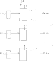
At first, vehicle head lamp 1 shown in Figure 25 is by constituting with the lower part: the light source module 2 that a plurality of LED2a are installed towards the place ahead side by side at the concavity substrate surface; Be configured in the projecting lens 3 in the place ahead of light source module 2; Be configured near the light-blocking member 4 of light source side focal position F of projecting lens 3.
Each LED2a of above-mentioned light source module 2 is configured to make separately optical axis towards the focal position of projecting lens 3 F, supplies with drive current respectively and be luminous by illustrated drive division never.
Above-mentioned projecting lens 3 is made of convex lens, and the light that each LED2a from light source module 2 is penetrated focuses on towards the place ahead and irradiation.
Above-mentioned light-blocking member 4 is formed with ora terminalis 4a, is used to form the shading graph as the luminous intensity distribution figure that becomes the meeting light beam.
According to the vehicle head lamp 1 of this structure, each LED2a of light source module 2 is luminous by being supplied to drive current, advances towards the focal position of projecting lens 3 F respectively from the light that each LED2a penetrates, and is focused and shines towards the place ahead by projecting lens 3.
At this moment, form shading graph by utilizing light-blocking member 4, as shown in figure 26, above-mentioned light shines towards the place ahead in the scope of the luminous intensity distribution figure L of so-called meeting light beam.Thus, do not penetrate dazzle to opposite car or pedestrian.
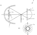
And vehicle head lamp 5 shown in Figure 27 is by constituting with the lower part: the light source module 6 that is made of a plurality of LED6a that are configured to ring-type around the central shaft that extends forwardly; Forwards reflect reflection of light mirror 7 from light source module 6; The projecting lens 3 that will focus on from the reverberation of speculum 7; Form the light-blocking member that blocks 4 that the meeting luminous intensity distribution is used.
Each LED6a of above-mentioned light source module 6 is configured to make each optical axis to extend towards the radial direction outside from central shaft shown in Figure 27 (B).
Above-mentioned speculum 7 for example is made of the ellipse of revolution face, and near each LED6a of configuration light source module 6 its first focal position makes its second focal position be positioned near the focal position of light source side of projecting lens 3 simultaneously.
At this moment, above-mentioned light forms by light-blocking member 4 and blocks, thereby as shown in figure 26, shines towards the place ahead in the scope of the luminous intensity distribution figure L of so-called meeting light beam.Thus, do not penetrate dazzle to opposite car or pedestrian.
But, in the vehicle head lamp 1 of this structure, constitute by the optical system that with Halogen lamp LED or discharge lamp is prerequisite, so be not suitable for LED is used as light source, be difficult to form desired luminous intensity distribution figure.Therefore, can not effectively utilize the illumination of penetrating from each LED to penetrate the place ahead.
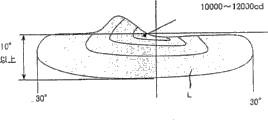
In addition, as shown in figure 26, in the meeting light beam of headlamp, near center position is so-called HV, for example need the luminous intensity of 6000cd to 20000cd approximately.
To this, in the optical system of utilizing projecting lens that light is focused on, luminous intensity values has near the density (luminous exitance) and the proportional relation of light fixture area of the light the focal position with projecting lens.Therefore, when the LED that obviously reduces of specific luminance was as light source mutually, in order to obtain above-mentioned luminous intensity by the aforementioned optical system in the past of utilizing speculum and projecting lens, it is very big that optical system will become at handle and discharge lamps such as Halogen lamp LED or HID.
And vehicle head lamp 5 shown in Figure 27 is difficult to obtain desired luminous intensity equally by speculum 7 each LED6a enlarging projection with light source module 6.
To this, can consider vehicle head lamp for example shown in Figure 28 8.
In Figure 28, vehicle head lamp 8 constitutes, at being configured to rectangular a plurality of LED9a in length and breadth, speculum 9b, projecting lens 9c and light-blocking member 9d are set respectively, utilize the speculum 9b of corresponding each LED9a and projecting lens 9c the picture of each LED9a towards front projection.
But, in the vehicle head lamp 8 of this structure, use the optical system of speculum 9b and projecting lens 9c identical with vehicle head lamp 5, be to be the structure of prerequisite, so be not suitable for equally LED as light source with Halogen lamp LED or discharge lamp.
In addition, in each above-mentioned vehicle head lamp 1,5,8, in order to form the luminous intensity distribution figure of the meeting light beam that shines road one side (being the left side during left driving) brighter, and have light-blocking member 4,9d, so that the driver of above-mentioned opposite car is dazzle-free, utilize this light-blocking member 4,9d to block unwanted light, obtain the luminous intensity distribution figure of above-mentioned meeting light beam thus.At this moment, for blocking of the luminous intensity distribution figure that forms corresponding meeting light beam, need utilize light-blocking member 4,9d to form and block near the highest part of brightness the optical axis of each LED2a, 6a, 9a.Therefore, in the amount of emitted light from each LED2a, 6a, 9a, for example nearly approximately 40% light quantity is blocked by light-blocking member 4,9d, forms loss light, so can not bring into play the luminous this optical signature of the face of LED, the utilization ratio of light is very low.
To this, if do not use light-blocking member 4,9d, only utilize speculum 7,9b to carry out the control of luminous intensity distribution figure, loss can be suppressed to bottom line, so the utilization ratio of light can bring up to about 70%, but because the brightness of each LED is low, so be difficult to obtain the contrast of abundance of the light and shade boundary line of H line (horizontal line) and sweep (15 parallaxs of spending tilt).
Summary of the invention
In view of the foregoing, the objective of the invention is to, a kind of vehicle head lamp that is suitable for headlamp, supplementary driving lamp etc. that a plurality of LED elements is used as light source and obtains desired luminous intensity distribution figure is provided.
Above-mentioned purpose is that the vehicle according to the invention headlamp reaches, and it is characterized in that, comprising: having the LED of employing is a plurality of light source modules of light source; Light from each light source module is shone towards the place ahead respectively, irradiation is to the optical system in the zone that differs from one another of the regulation of luminous intensity distribution figure, each optical system constitutes and is suitable for most to regulation area illumination light, and each light source module has the LED that corresponding relatively optical system is best configuration simultaneously.
Preferred above-mentioned each light source module of vehicle head lamp of the present invention and optical system are respectively to optically focused zone, the diffusion zone irradiates light of luminous intensity distribution figure.
Preferred above-mentioned each light source module of vehicle head lamp of the present invention and optical system are respectively to optically focused zone, diffusion zone and the zone line irradiates light of luminous intensity distribution figure.
Vehicle head lamp of the present invention preferably comprises having the shape light-blocking member identical with the luminous intensity distribution figure of meeting light beam to the light source module of the optically focused zone of above-mentioned luminous intensity distribution figure irradiates light, and corresponding optical system is made of the projecting lens that light is focused on.
Vehicle head lamp of the present invention preferably has long luminous shape on the light source module of the diffusion zone irradiates light of above-mentioned luminous intensity distribution figure has a direction of straight line crest line, corresponding optical system is by constituting from the light reflection of light source module and the speculum of optically focused.
Vehicle head lamp of the present invention preferably is made of speculum and projecting lens to the optical system of the zone line irradiates light of above-mentioned luminous intensity distribution figure, makes being connected of light distribution characteristic formation continuously smooth of optically focused zone and diffusion zone.
Vehicle head lamp of the present invention preferably also has light source module and the optical system that is suitable for most to the luminous intensity distribution area illumination light of auxiliary lamp.
The luminous intensity distribution zone of the preferred above-mentioned auxiliary lamp of vehicle head lamp of the present invention is the luminous intensity distribution zone of lamp, fog lamp or cornering lamp in the daytime.
Vehicle head lamp of the present invention preferably also have be suitable for most to luminous intensity distribution area illumination light arbitrarily be configured to can dismounting light source module and optical system.
Led chip number, configuration and the structure that preferred each light source module of vehicle head lamp of the present invention constitutes the luminous intensity distribution zone of corresponding irradiates light is respectively different types of packaging body of optimal design.
According to above-mentioned formation, the luminous intensity distribution figure is divided into a plurality of zones, at each zone light source module and optical system are set respectively.And, reaching optimization by the zone that makes corresponding respectively these light source modules and optical system, each zone that forms the luminous intensity distribution figure has the light distribution characteristic that desired luminous intensity distributes respectively.
Thus, by vehicle head lamp as a whole with the combination of multiple sets of light sources module and optical system, can form and have the desired luminous intensity distribution figure that desired luminous intensity distributes.At this moment, each LED of each light source module reaches optimization with optics system pairing relatively together luminous intensity distribution graphics field, thereby improves the utilization ratio from the light of each LED, can obtain bright more irradiates light.
In above-mentioned each light source module and optical system during respectively to the optically focused zone of luminous intensity distribution figure, diffusion zone irradiates light, reach optimization by optically focused zone and the diffusion zone that makes relative each luminous intensity distribution figure of each light source module, thereby can distribute to each optically focused zone, diffusion zone irradiates light with desired luminous intensity with optical system.Thus, can form the luminous intensity distribution figure that desired luminous intensity distributes on the whole.
In above-mentioned each light source module and optical system during respectively to the optically focused zone of luminous intensity distribution figure, diffusion zone and zone line irradiates light, reach optimization by optically focused zone, diffusion zone and the zone line that makes relative each luminous intensity distribution figure of each light source module, can distribute to each optically focused zone, diffusion zone irradiates light with desired luminous intensity with optical system.Thus, can form the luminous intensity distribution figure that desired luminous intensity distributes on the whole, simultaneously can be by the contrast connection optically focused zone and the diffusion zone of zone line with continuously smooth.
Light source module to the optically focused zone of above-mentioned luminous intensity distribution figure irradiates light comprises having the shape light-blocking member identical with the luminous intensity distribution figure of meeting light beam, when the optical system of correspondence is made of the projecting lens that light is focused on, form by light-blocking member from the light of each LED of this light source module and to block, and by blocking that the luminous shape that forms is projected that lens focus on and towards front projection, thus, utilize simple structure for example forming the high light and shade boundary line of contrast near the center, so can form the luminous intensity distribution figure that is fit to the optically focused zone.
Have to the light source module of the diffusion zone irradiates light of above-mentioned luminous intensity distribution figure on the direction of straight line crest line and have long luminous shape, when the optical system of correspondence is made of from the reflection of light mirror of light source module reflection, use the light source module that for example led chip is configured to linearity, by this straight line crest line of mirror reflects and irradiation forwards, thus forwards usable reflection from the light of light source module, simultaneously blocking near the projection straight line crest line line, thereby can form the high light and shade boundary line of contrast, so can be formed in the luminous intensity distribution figure of the suitable diffusion zone of horizontal line direction diffusion (block line have light and shade poor).And, light source module come down to face luminous, spread luminously fully, so speculum need not cover light source integral body, form shape, so can make the whole thin type structure that forms of vehicle head lamp near the plane.
Optical system to the zone line irradiates light of above-mentioned luminous intensity distribution figure is made of speculum and projecting lens, when connecting the light distribution characteristic of optically focused zone and diffusion zone continuously smoothly, the spread slightly that spreads by speculum and be focused by projecting lens towards the place ahead irradiation.Blocking is that shadow shield by being positioned at lens focus forms, so can connect smoothly between the luminous intensity distribution figure of diffusion in the horizontal direction of the luminous intensity distribution figure of light and shade boundary line of formation high-contrast in optically focused zone and diffusion zone.
In addition, also have the light source module and the optical system that are suitable for most to the luminous intensity distribution area illumination light of auxiliary lamp, when preferably being the luminous intensity distribution zone of lamp, fog lamp or cornering lamp in the daytime in the luminous intensity distribution zone of above-mentioned auxiliary lamp, can utilize the function that is assemblied in interior light source module of this vehicle head lamp and optical system realization auxiliary lamp, make the whole small-scale structure that forms of lamps apparatus for vehicle, relax the design freedom of lamps apparatus for vehicle and automobile.
In addition, have and be suitable for most when any luminous intensity distribution area illumination light and light source module that can dispose removably and optical system, can add or remove the function of auxiliary lamp and other lamps apparatus for vehicle as required, so constitute lamps apparatus for vehicle easily with any function.
When led chip number, configuration and the structure that each light source module constitutes the luminous intensity distribution zone of corresponding irradiates light is respectively the different types of packaging body of optimal design, the regulation zone that each light source module constitutes the luminous intensity distribution figure of corresponding this irradiates light makes these led chip numbers, configuration and structure reach optimized packaging body, so, can constitute vehicle head lamp according to the combination of this packaging body kind.
Like this, according to the present invention, utilization is the light source module of LED as light source, make the regulation zone of passing through corresponding irradiation optical system luminous intensity distribution figure from the light of each LED, make this moment the corresponding respectively luminous intensity distribution graphics field of light source module and optical system reach optimization, by combination multiple sets of light sources module and optical system, can realize having the desired luminous shape and the light distribution characteristic of Luminance Distribution on the whole thus.
Therefore, even the discharge lamp LED that specific luminance is lower mutually of use and Halogen lamp LED or HID etc. during as light source, also can obtain sufficient maximum emission intensity, so can realize high efficiency and small-sized slim vehicle head lamp.
And, by the combination of light source module, can form desired light distribution characteristic, so can increase the free degree of luminous intensity distribution and the design freedom of vehicle head lamp.
Description of drawings
Fig. 1 is the skeleton diagram of formation of first embodiment of expression vehicle head lamp of the present invention.
Fig. 2 is the approximate three-dimensional map of formation of first group of Lighting Division of the vehicle head lamp of presentation graphs 1.
Fig. 3 is the amplification stereogram of formation of light source module of first group of Lighting Division of presentation graphs 2.
Fig. 4 is the summary side elevation of formation of variation of first group of Lighting Division of presentation graphs 2.
Fig. 5 is the curve map of the luminous intensity distribution figure of expression first group of Lighting Division shown in Figure 4.
Fig. 6 is the approximate three-dimensional map of formation of second group of Lighting Division of the vehicle head lamp of presentation graphs 1.
Fig. 7 is the skeleton diagram of an example of shape of illuminating part of light source module of second group of Lighting Division of presentation graphs 6.
Fig. 8 is the skeleton diagram of light source projection image of second group of Lighting Division of presentation graphs 6.
Fig. 9 is the curve map of luminous intensity distribution figure of second group of Lighting Division of presentation graphs 6.
Figure 10 is the skeleton diagram of other examples of shape of illuminating part of light source module of second group of Lighting Division of presentation graphs 6.
Figure 11 is the approximate three-dimensional map of other other examples of shape of illuminating part of light source module of second group of Lighting Division of presentation graphs 6.
Figure 12 is the summary side elevation of an example of formation of the 3rd group of Lighting Division of the vehicle head lamp of presentation graphs 1.
Figure 13 is the summary side elevation of other examples of formation of the 3rd group of Lighting Division of the vehicle head lamp of presentation graphs 1.
Figure 14 is the summary side elevation of other other examples of formation of the 3rd group of Lighting Division of the vehicle head lamp of presentation graphs 1.
Figure 15 is the summary side elevation of variation of the 3rd group of Lighting Division of expression Figure 12.
Figure 16 is the summary side elevation of other variation of the 3rd group of Lighting Division of expression Figure 12.
Figure 17 is the skeleton diagram of formation of second embodiment of expression vehicle head lamp of the present invention.
Figure 18 is the approximate three-dimensional map of formation of first group of Lighting Division of the vehicle head lamp of expression Figure 17.
Figure 19 is the approximate three-dimensional map of formation of second group of Lighting Division of the vehicle head lamp of expression Figure 17.
Figure 20 is the approximate three-dimensional map of formation of the 3rd group of Lighting Division of the vehicle head lamp of expression Figure 17.
Figure 21 is the curve map of luminous intensity distribution figure of first group of Lighting Division of expression Figure 18.
Figure 22 is the curve map of luminous intensity distribution figure of second group of Lighting Division of expression Figure 19.
Figure 23 is the curve map of luminous intensity distribution figure of the 3rd group of Lighting Division of expression Figure 20.
Figure 24 is the curve map of luminous intensity distribution figure of the vehicle head lamp of expression Figure 17.
Figure 25 is a summary side elevation of representing an example formation of vehicle head lamp in the past.
Figure 26 is the curve map that the luminous intensity distribution figure of meeting light beam represented in summary.
Figure 27 is the summary side elevation of formation of representing other examples of vehicle head lamp in the past.
Figure 28 is the summary side elevation of formation of representing other other examples of vehicle head lamp in the past.
Among the figure: 10 vehicle head lamps; 11 first groups of Lighting Divisions; 12 light source modules; 12a illuminating part (LED); The 12e light-blocking member; 13 optical systems (projecting lens); 21 second groups of Lighting Divisions; 22 light source modules; 22a illuminating part (LED); 23 optical systems (speculum); 31 the 3rd groups of Lighting Divisions; 32 light source modules; 32a, 32a ' illuminating part (LED); 33 optical systems; 33a, 33a ' speculum; The 33b projecting lens; The 33c light-blocking member; 40 vehicle head lamps; 41 first groups of Lighting Divisions; 42a, 42b, 42c, 42d light source module; 43a, 43b, 43c, 43d optical system (projecting lens); 51 second groups of Lighting Divisions; 52a, 52b light source module; 53a, 53b optical system (projecting lens); 61 the 3rd groups of Lighting Divisions; 62a, 62b, 62c light source module; 33 optical systems; 63a, 63b, 63c speculum; 64 projecting lens; 65 light-blocking members.
The specific embodiment
Below, describe preferred implementation of the present invention in detail with reference to Fig. 1~Figure 24.
In addition, the embodiment of the following stated is a preferred concrete example of the present invention, thus carried out various preferred qualifications technically, but short of in the following description special qualification record of the present invention, scope of the present invention just is not limited to these embodiments.
(embodiment 1)
Fig. 1 represents the formation of first embodiment of vehicle head lamp of the present invention.In Fig. 1, vehicle head lamp 10 is made of three groups of Lighting Divisions 11,21,31.
First group of Lighting Division 11 constitutes the optically focused zone irradiates light of the maximum emission intensity of the light and shade boundary line of containing sweep etc. in the luminous intensity distribution figure of so-called meeting light beam.
And it is the diffusion zone irradiates light that second group of Lighting Division 21 constitutes the broad range zone that does not need sweep in above-mentioned luminous intensity distribution figure.
In addition, the 3rd group of Lighting Division 31 constitutes the zone line irradiates light in above-mentioned luminous intensity distribution figure, so that connect the luminous intensity distribution contrast of above-mentioned optically focused zone and diffusion zone smoothly.
At first, illustrate that optically focused is regional with first group of Lighting Division 11.
First group of Lighting Division 11 is made of light source module 12 and optical system 13 as shown in Figure 2.
Light source module 12 comprises the illuminating part 12a that is made of the LED that utilizes fluorophor to surround led chip as shown in Figure 3, for example utilizes resin system lens housing 12b to encapsulate.Above-mentioned illuminating part 12a is powered from the outside by lead 12c, the light contact fluorophor that penetrates from led chip, and the mixed light of the exciting light that forms from the light of led chip with by fluorophor injects to the outside.
Above-mentioned light source module 12 also comprises lens 12d and light-blocking member 12e in the place ahead of illuminating part 12a, for the light that comes self-luminescent part 12a, block figure by utilizing light-blocking member 12e to block to form, only need to carry out projection by usage level line and convex lens (projecting lens), can form the sweep as the feature of the luminous intensity distribution figure of meeting light beam, this sweep for example tilts to extend upward with 15 degree from the center of luminous intensity distribution figure.
Above-mentioned optical system 13 is to constitute projecting lens by convex lens, as shown in Figure 2, be configured to make its optical axis consistent on the central shaft of light source module 12, and the focal position of its light source side is positioned near the light-blocking member 12e in illuminating part 12a the place ahead of light source module 12.
Thus, by make light from each LED12a of light source module 12 by optical system 13 towards the place ahead optically focused, thereby be formed on the luminous intensity distribution graphics field of representing with symbol La among Fig. 2 (optically focused zone).
Herein, optical system 13 is light-gathering optics, though so also can use the light-gathering optics of other structures, but the maximum emission intensity value in the optically focused zone of luminous intensity distribution figure and secondary optical system are that the area of near the focal position of optical system 13 brightness and optical system 13 is proportional, so that the illuminating part 12a of light source module 12 directly can obtain the best high-high brightness of efficient to the structure shown in Figure 2 of optically focused region projection by projecting lens.
To this, when near near the light-blocking member 12e being disposed at the lens outside of light source module the focal position of projecting lens being set, brightness reduces significantly, so the maximum emission intensity value also reduces significantly.
And, using image rotation lenses that the picture of illuminating part 12a is imaged near the light-blocking member 12e, and by projecting lens this picture under the situation of the optical system of optically focused region projection, optical system complicates, component costs and assembly cost improve, and the vehicle head lamp state degree of depth increases, and the brightness of the picture of the illuminating part 12a of focal position simultaneously reduces, and makes the maximum emission intensity value in optically focused zone reduce too.
Herein, above-mentioned first group of Lighting Division 11 optically focused zone of being difficult in the luminous intensity distribution figure provides Luminance Distribution arbitrarily.So, as shown in Figure 4, a plurality of (illustrated case is four) first group of Lighting Division 11a, 11b, 11c, 11d are set, light L1, L2, L3, L4 from light source module 12a ', 12b ', 12c ', 12d ' are distinguished mutually different optical system 13a, 13b, 13c, 13d towards front projection by focal length, thus as shown in Figure 5, according to each Lighting Division 11a, 11b, the suitable repeatedly setting range of exposures of 11c, 11d, can make that to have Luminance Distribution on the whole be stratified light distribution characteristic.
Below, illustrate that diffusion zone is with second group of Lighting Division 21.
Second group of Lighting Division 21 is made of light source module 22 and optical system 23 as shown in Figure 6.
And, optical system 23 is made of the speculum that is combined to form towards for example paraboloid of revolution of the concavity in the place ahead or ellipse of revolution face etc. in this case, be configured to relatively, and its focal position be positioned near the illuminating part 22a of light source module 22 with the axle of light source module 22.
Thus, be reflected by optical system 23, form the luminous intensity distribution graphics field of representing with symbol Lb among Fig. 6 (diffusion zone) from the light of the illuminating part 22a of light source module 22.
Under this situation, light source module 22 is that face is luminous, and performance has an advantage that spreads luminous directional property fully, and the utilization ratio of the light that penetrates from the illuminating part 22a of light source module 22 reaches about more than 70%, and, can form desired luminous intensity distribution figure by suitably selecting mirror shapes.
At this moment, the straight line crest line of the illuminating part 22a of light source module 22 is configured in horizontal direction, towards front projection, blocks thereby can be used to form the horizontal of luminous intensity distribution figure to this crest line by optical system 23.
In addition, above-mentioned second group of Lighting Division, the 21 preferred speculums that constitute above-mentioned optical system 23 constitute the multiple reflection mirror that is divided into a plurality of reflectings surface, by each reflecting surface of suitable formation, according to shown in Figure 8, with the illuminating part 22a projection of light source module 22.In this case, rotate and projection in the projection image of the position illuminating part 22a that reflects.
Thus, the projection image of the illuminating part 22a of the diffusion zone of luminous intensity distribution figure by making each reflecting surface overlaps, and can have luminous intensity shown in Figure 9 and distribute promptly stratified light distribution characteristic.
In addition, the illuminating part 22a of light source module 22 is not limited to rectangle, as shown in figure 10, also can form and has the roughly shape of semicircle profile, also can be configured in a direction to a plurality of led chips side by side as shown in figure 11.
At last, illustrate that zone line is with the 3rd group of Lighting Division 31.
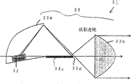
The 3rd group of Lighting Division 31 is made of light source module 32 and optical system 33 as shown in figure 12.
In addition, in this case, the shape of the illuminating part 32a of light source module 32 without limits, but in order to improve incident efficient to the projecting lens 33b of optical system 33, make the size miniaturization more of optical system, preferred illuminating part 32a is for as far as possible little and brightness is higher.
Herein, speculum 33a for example is made of the ellipse of revolution face, is configured to make a side focal position to be positioned near the center of illuminating part 32a of light source module 32, and the opposing party's focal position is positioned on the optical axis of optical system 33 forwardly.
Projecting lens 33b is convex lens, is configured to make the focal position of its light source side to be positioned near the focal position, the place ahead of speculum 33a.
In addition, above-mentioned light-blocking member 33c is configured near the focal position of light source side of projecting lens 33b, and its ora terminalis 33d forms in the upper end and blocks.
In addition, in said structure, though be that illuminating part 32a is configured to towards the top, speculum 33a has only disposed the first half, but be not limited thereto, as shown in figure 13, except that above-mentioned illuminating part 32a, also can have illuminating part 32a ' down, can have the latter half speculum 33a ' paired up and down simultaneously with speculum 32a.
And, as shown in figure 14, also can dispose light-blocking member 33c along optical axis, its ora terminalis 33d forms at front end and blocks.Thus, a part of light that incides light-blocking member 33d surface is reflected and towards the place ahead irradiation, thereby can bring up to the utilization ratio of light more than 50%.
At this moment, as shown in figure 15, in order further to improve the contrast of blocking line, can with illuminating part 32a towards the rear tilted configuration a little.
In addition, in the optical system of Figure 16, led light source is the face illuminating source, reflecting surface only be present in the lens centre above or below situation under since only below the center of projecting lens 33b or above incident light, so by the first half or the latter half of projecting lens 33b are blocked, can on above-below direction, realize miniaturization, simultaneously in order to obtain the luminous intensity distribution figure of high luminous intensity, on above-below direction during a plurality of Lighting Division 31 of repeated configuration, can be in the intensive configuration of above-below direction.
The vehicle head lamp 10 of embodiment of the present invention is by forming above structure, and the light source module 12,22,32 of each Lighting Division 11,21,31 is luminous by being powered respectively.
Thus, the light that penetrates from the illuminating part 12a of light source module 12 forms by light-blocking member 12e and blocks, and by the projecting lens optically focused of optical system 13 and towards the place ahead irradiation, thereby forms the optically focused zone La of luminous intensity distribution figure.
And the light that penetrates from the illuminating part 22a of light source module 22 is reflected by the speculum of optical system 23, and towards the place ahead irradiation, thereby forms the diffusion zone Lb of luminous intensity distribution figure.
In addition, the light that penetrates from the illuminating part 32a of light source module 32 is reflected by the speculum 33a of optical system 33, and by projecting lens 33b optically focused, form by light-blocking member 33c simultaneously and block, and towards the place ahead irradiation, thereby form the optically focused zone La of luminous intensity distribution figure and the zone line between the diffusion zone Lb.
Thus, overlap, can form luminous intensity distribution figure towards the so-called meeting light beam in the place ahead from the irradiates light of each Lighting Division 11,21,31.At this moment, a plurality of zones of luminous intensity distribution figure, be that optically focused zone, diffusion zone and the zone line between them form by first group of Lighting Division 11, second group of Lighting Division 21, the 3rd group of Lighting Division 31 respectively.Herein, each Lighting Division 11,21,31 constitutes and is suitable for corresponding zone respectively most, and each zone and luminous intensity distribution figure integral body distribute with desired luminous intensity and forms maximum emission intensity.
Like this, vehicle according to the invention headlamp 10 uses a plurality of LED as light source, can obtain the luminous intensity distribution figure of the desired for example so-called meeting light beam of luminous intensity distribution figure.
(embodiment 2)
Figure 17 represents the formation of second embodiment of vehicle head lamp of the present invention.
In Figure 17, vehicle head lamp 40 is specific embodiment of aforementioned vehicle headlamp 10, and is identical with vehicle head lamp shown in Figure 1 10, is made of three groups of Lighting Divisions 41,51,61.
In this case, first group of Lighting Division 11 of the formation of first group of Lighting Division 41 in corresponding optically focused zone and vehicle head lamp shown in Figure 1 is roughly the same, spends the scope irradiates light of right 8 degree from a left side 8.
And second group of Lighting Division 21 of the formation of second group of Lighting Division 51 of corresponding diffusion zone and vehicle head lamp shown in Figure 1 is roughly the same, to the scope internal radiation light of spending right 50 degree from a left side 50.
In addition, the 3rd group of Lighting Division 31 of the formation of the 3rd group of Lighting Division 61 of corresponding zone line and vehicle head lamp shown in Figure 1 is roughly the same, to the scope internal radiation light of spending right 20 degree from a left side 20.
In addition, each zone is that the luminous intensity distribution ratio (light beam ratio) of optically focused zone, zone line and diffusion zone is preferably set to 1: 2: 4 relatively.
Above-mentioned first group of Lighting Division 41 is made of a plurality of (illustrated case is four) light source module 42a, 42b, 42c, 42d and corresponding respectively projecting lens 43a, 43b, 43c, 43d as shown in figure 18.The formation of each light source module 42a, 42b, 42c, the 42d light source module 12 with first group of Lighting Division 11 of vehicle head lamp 10 respectively is identical.
And each projecting lens 43a, 43b, 43c, 43d are identical with formation shown in Figure 4, have mutually different focal length.
And the focal length by suitable selection each projecting lens 43a, 43b, 43c, 43d can obtain luminous intensity and projection size on the projection screen.
Above-mentioned second group of Lighting Division 51 is made of a plurality of (illustrated case is two) light source module 52a, 52b and corresponding respectively speculum 53a, 53b as shown in figure 19.
The formation of each light source module 52a, the 52b light source module 22 with second group of Lighting Division 21 of vehicle head lamp 10 respectively is identical, disposes back-to-back at left and right directions.
Herein, the illuminating part of each light source module 52a, 52b has for example similar rectangular more than one straight line crest line, and the filament of this crest line ratio Halogen lamp LED in the past or the arc electrode shape of HID are long, for example preferably have the double length of filament.Particularly as shown in figure 11,, the light beam of light source packaging body self can be increased, the vehicle head lamp integral miniaturization can be made simultaneously by using the so-called how chip-shaped light source packaging body of a plurality of led chip straight line configuration in a packaging body.
And the formation of each speculum 53a, the 53b speculum 23 with second group of Lighting Division 21 of vehicle head lamp 10 respectively is identical, is configured to expand at left and right directions.
Thus, the illuminating part of above-mentioned light source module 52a, 52b has long straight line crest line, according to the shape of speculum 53a, 53b, can control the projection image position of illuminating part arbitrarily, can shine 70% above light beam of the light beam of self-luminescent part towards the place ahead.
Above-mentioned the 3rd group of Lighting Division 61 as shown in figure 20, by a plurality of (illustrated case is three) light source module 62a, 62b, 62c, respectively corresponding speculum 63a, 63b, 63c, projecting lens 64 and light-blocking member 65 constitute.
The formation of each light source module 62a, 62b, the 62c light source module 32 with the 3rd group of Lighting Division 31 of vehicle head lamp 10 respectively is identical, simultaneously around central shaft with the angle same arranged spaced.
Herein, the illuminating part of each light source module 62a, 62b, 62c is preferably as far as possible little, for example is chosen to be less than the filament of in the past Halogen lamp LED or the arc electrode shape of HID.
And the structure of each speculum 63a, 63b, the 63c speculum 33a with the 3rd group of Lighting Division 31 of vehicle head lamp 10 respectively is identical, and corresponding each light source module 62a, 62b, 62c are configured in the top and the both sides of optical axis.
In addition, the projecting lens 33b of the 3rd group of Lighting Division 31 of projecting lens 64 and vehicle head lamp 10 is identical, only disposes one on optical axis.
And the light-blocking member 33c of the 3rd group of Lighting Division 31 of light-blocking member 65 and vehicle head lamp 10 is identical, is configured near the light source side focal position of projecting lens 64.
In addition, when use has the light source module of straight line illuminating part, in order to be formed on the luminous intensity distribution figure of left and right directions expansion, for the corresponding light source module of speculum that is positioned at the optical axis top, preferably the longitudinally of its illuminating part and optical axis arranged perpendicular.And, for the light source module corresponding, preferably the longitudinally of its illuminating part and optical axis configured in parallel with the speculum that is positioned at the optical axis side.Thus, the projection image of the illuminating part that forms by speculum is long in the horizontal direction extends longways, can easier formation luminous intensity distribution figure.
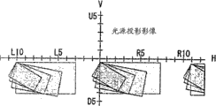
According to vehicle head lamp 40, the first Lighting Divisions 41 of this structure as shown in figure 21, to optically focused zone irradiates light La, second Lighting Division 51 as shown in figure 22, to diffusion zone irradiates light Lb, the 3rd Lighting Division 61 as shown in figure 23, the zone line irradiates light Lc between optically focused zone and diffusion zone.
And, overlap by luminous intensity distribution figure La, Lb, the Lc that makes each Lighting Division 41,51,61, as shown in figure 24, can form the luminous intensity distribution figure L that is suitable for the meeting light beam.
In the above-described embodiment,, be not limited thereto, also can omit the Lighting Division 31,61 of corresponding zone line though vehicle head lamp 10,40 has the Lighting Division 11,21,31 or 41,51,61 of corresponding optically focused zone, diffusion zone and zone line respectively.And, at these Lighting Divisions, the Lighting Division of the luminous intensity distribution figure of the function by appending the supplementary driving lamp that for example has the auxiliary lamp that is used to realize lamp, cornering lamp in the daytime or fog lamp or so-called AFS lamp, perhaps the luminous intensity distribution figure is divided into more zone, new Lighting Division is appended in the zoning relatively, can utilize a vehicle head lamp to form multi-functional luminous intensity distribution figure.
At this moment, by make the Lighting Division that newly appends constitute can dismounting form, can utilize and choose parts and append or remove this Lighting Division arbitrarily.
In addition, in the above-described embodiment, be defined in the situation of left driving with light distribution characteristic as the meeting light beam, in order to make it not penetrate dazzle to the right side of vehicle front opposite car, form shadow shield 12e, 33c, 65 ora terminalis, but be not limited thereto, when travelling on the right side, reversed left to right by the ora terminalis configuration that makes the shadow shield in the vehicle head lamp, can obtain identical effect.
Claims (12)
1. vehicle head lamp, this vehicle head lamp is characterised in that to have a plurality of combinations, and each combination is made of light source module and optical system, and wherein, it is light source that described light source module adopts LED; And described optical system makes described light source module respectively towards the place ahead and to the area illumination that differs from one another of the regulation of the luminous intensity distribution figure light from above-mentioned light source module,
The combination of above-mentioned light source module and optical system comprises the combination in the optically focused zone that shines the luminous intensity distribution figure, and to the combination of diffusion zone irradiates light, is combined to form the luminous intensity distribution figure of a whole regulation by these.
2. vehicle head lamp according to claim 1, it is characterized in that, the optical system that is used to shine the combination in above-mentioned optically focused zone is the projecting lens that is made of convex lens, and be used for optical system to the combination of above-mentioned diffusion zone irradiates light by the light of reflection, and the speculum that this illumination is mapped to the place ahead is constituted from light source module.
3. vehicle head lamp according to claim 1 is characterized in that, the optical system that is used to shine the combination in above-mentioned optically focused zone is to be made of speculum, projecting lens and light-blocking member.
4. according to claim 1,2 or 3 described vehicle head lamps, it is characterized in that the combination of above-mentioned light source module and optical system also comprises the combination to the zone line irradiates light.
5. vehicle head lamp according to claim 4 is characterized in that, is made of speculum and projecting lens to the optical system of the zone line irradiates light of above-mentioned luminous intensity distribution figure, makes being connected of light distribution characteristic formation continuously smooth of optically focused zone and diffusion zone.
6. vehicle head lamp according to claim 3 is characterized in that, above-mentioned light-blocking member is configured near the focal position of light source side of projecting lens, and the ora terminalis of described light-blocking member forms in the upper end and blocks.
7. vehicle head lamp according to claim 1 is characterized in that, is made of a plurality of light source modules and corresponding respectively speculum to the combination of above-mentioned diffusion zone irradiates light, and each light source module disposes back-to-back at left and right directions.
8. vehicle head lamp according to claim 7 is characterized in that, the illuminating part of each light source module has more than one straight line crest line, and the length of described straight line crest line is the twice of the length of filament.
9. vehicle head lamp according to claim 1 is characterized in that, also has the light source module and the optical system that are suitable for to the luminous intensity distribution area illumination light of auxiliary lamp.
10. vehicle head lamp according to claim 9 is characterized in that, the luminous intensity distribution zone of above-mentioned auxiliary lamp is the luminous intensity distribution zone of lamp, fog lamp or cornering lamp in the daytime.
11. vehicle head lamp according to claim 1 is characterized in that, also has to be suitable for to any luminous intensity distribution area illumination light and to be configured to dismounting light source module and optical system freely.
12. vehicle head lamp according to claim 1 is characterized in that, light source module constitute corresponding irradiates light the luminous intensity distribution zone led chip quantity, configuration and structure and be respectively different types of packaging body.
Applications Claiming Priority (2)
| Application Number | Priority Date | Filing Date | Title |
|---|---|---|---|
| JP2003364866 | 2003-10-24 | ||
| JP2003364866A JP4402425B2 (en) | 2003-10-24 | 2003-10-24 | Vehicle headlamp |
Publications (2)
| Publication Number | Publication Date |
|---|---|
| CN1609503A CN1609503A (en) | 2005-04-27 |
| CN100559058C true CN100559058C (en) | 2009-11-11 |
Family
ID=34386546
Family Applications (1)
| Application Number | Title | Priority Date | Filing Date |
|---|---|---|---|
| CNB2004100809614A Expired - Fee Related CN100559058C (en) | 2003-10-24 | 2004-10-10 | Vehicle head lamp |
Country Status (4)
| Country | Link |
|---|---|
| US (4) | US7059755B2 (en) |
| EP (1) | EP1526328B1 (en) |
| JP (1) | JP4402425B2 (en) |
| CN (1) | CN100559058C (en) |
Cited By (2)
| Publication number | Priority date | Publication date | Assignee | Title |
|---|---|---|---|---|
| CN102062341A (en) * | 2009-11-12 | 2011-05-18 | 斯坦雷电气株式会社 | Vehicle light |
| CN104235730A (en) * | 2010-10-29 | 2014-12-24 | 夏普株式会社 | Light emitting device, illumination device, vehicle headlamp and vehicle |
Families Citing this family (62)
| Publication number | Priority date | Publication date | Assignee | Title |
|---|---|---|---|---|
| JP4402425B2 (en) * | 2003-10-24 | 2010-01-20 | スタンレー電気株式会社 | Vehicle headlamp |
| JP4771723B2 (en) * | 2005-03-24 | 2011-09-14 | 市光工業株式会社 | Vehicle lighting |
| FR2889288B1 (en) * | 2005-07-26 | 2015-07-31 | Valeo Vision | LIGHTING DEVICE WITH MULTIPLE OPTICAL MODULES FOR MOTOR VEHICLE |
| DE102005041234A1 (en) * | 2005-08-31 | 2007-03-01 | Hella Kgaa Hueck & Co. | Headlight for vehicle, has optical units with characteristics in front of groups of sources in such a manner that different large light spots can be generated in traffic space by alternative switching on and off and/or dimming of sources |
| DE102005059524A1 (en) | 2005-09-30 | 2007-04-05 | Osram Opto Semiconductors Gmbh | Housing for an electromagnetic radiation-emitting optoelectronic component, component and method for producing a housing or a component |
| JP4676865B2 (en) | 2005-11-08 | 2011-04-27 | 株式会社小糸製作所 | Vehicle lighting device |
| US8089080B2 (en) * | 2005-12-28 | 2012-01-03 | Group Iv Semiconductor, Inc. | Engineered structure for high brightness solid-state light emitters |
| US7888686B2 (en) * | 2005-12-28 | 2011-02-15 | Group Iv Semiconductor Inc. | Pixel structure for a solid state light emitting device |
| US7800117B2 (en) * | 2005-12-28 | 2010-09-21 | Group Iv Semiconductor, Inc. | Pixel structure for a solid state light emitting device |
| JP4675874B2 (en) * | 2006-01-20 | 2011-04-27 | 株式会社小糸製作所 | Lighting fixtures for vehicles |
| US20090173491A1 (en) * | 2006-02-24 | 2009-07-09 | O'brien Thomas B | Method and system for extraction of hydrocarbons from oil shale and limestone formations |
| US20080055065A1 (en) * | 2006-08-30 | 2008-03-06 | David Charles Feldmeier | Systems, devices, components and methods for controllably configuring the brightness of light emitted by an automotive LED illumination system |
| US20080055896A1 (en) * | 2006-08-30 | 2008-03-06 | David Charles Feldmeier | Systems, devices, components and methods for controllably configuring the color of light emitted by an automotive LED illumination system |
| DE102006043298A1 (en) * | 2006-09-14 | 2008-03-27 | Hella Kgaa Hueck & Co. | Projection head light for vehicles, has reflector having two focal points, where light source device is arranged in former focal point of reflector |
| JP4953922B2 (en) * | 2007-05-30 | 2012-06-13 | 株式会社小糸製作所 | Vehicle headlamp |
| EP2034235B1 (en) * | 2007-09-04 | 2013-11-06 | Hella KGaA Hueck & Co. | Headlamp for vehicles |
| DE102007049309B4 (en) * | 2007-10-15 | 2013-04-11 | Automotive Lighting Reutlingen Gmbh | Projection module of a motor vehicle headlight |
| CN101447961A (en) | 2007-11-26 | 2009-06-03 | 大唐移动通信设备有限公司 | Method, system and device for signal generation and information transmission in broadband wireless communication |
| JP2009179113A (en) | 2008-01-29 | 2009-08-13 | Koito Mfg Co Ltd | Head lamp device for vehicle and its control method |
| JP5152502B2 (en) | 2008-06-09 | 2013-02-27 | スタンレー電気株式会社 | Lamp |
| KR20160105527A (en) | 2008-07-10 | 2016-09-06 | 쓰리엠 이노베이티브 프로퍼티즈 컴파니 | Viscoelastic lightguide |
| DE102008036194B4 (en) * | 2008-08-02 | 2016-10-20 | Automotive Lighting Reutlingen Gmbh | Light module for a lighting device for a motor vehicle |
| DE102008036192B4 (en) * | 2008-08-02 | 2012-05-03 | Automotive Lighting Reutlingen Gmbh | Automotive lighting device |
| EP2321677A4 (en) | 2008-08-08 | 2011-08-17 | 3M Innovative Properties Co | Lightguide having a viscoelastic layer for managing light |
| JP5195296B2 (en) | 2008-10-30 | 2013-05-08 | 市光工業株式会社 | Vehicle headlamp |
| DE112009004314T5 (en) * | 2009-02-16 | 2012-04-26 | Mitsubishi Electric Corp. | Lighting device for a headlight source |
| US8080942B2 (en) * | 2009-02-24 | 2011-12-20 | Volkswagen Ag | System and method for electronic adaptive front-lighting |
| JP5381351B2 (en) * | 2009-06-03 | 2014-01-08 | スタンレー電気株式会社 | Vehicle lighting |
| FR2948439B1 (en) * | 2009-07-21 | 2011-08-05 | Valeo Vision | LIGHTING MODULE FOR A MOTOR VEHICLE PROJECTOR, AND PROJECTOR EQUIPPED WITH AT LEAST ONE SUCH MODULE. |
| DE102009049458A1 (en) | 2009-10-15 | 2011-04-28 | Hella Kgaa Hueck & Co. | Projection headlamps for vehicles |
| JP5397186B2 (en) * | 2009-11-24 | 2014-01-22 | スタンレー電気株式会社 | Vehicle lighting |
| US8314558B2 (en) * | 2010-01-12 | 2012-11-20 | Ford Global Technologies, Llc | Light emitting diode headlamp for a vehicle |
| FR2955538B1 (en) * | 2010-01-26 | 2015-08-21 | Valeo Vision | OPTICAL DEVICE, IN PARTICULAR FOR MOTOR VEHICLE |
| WO2011106860A1 (en) | 2010-03-01 | 2011-09-09 | Group Iv Semiconductor, Inc. | Deposition of thin film dielectrics and light emitting nano-layer structures |
| KR101236860B1 (en) * | 2010-04-07 | 2013-02-26 | 이치코 고교가부시키가이샤 | Headlight for vehicles |
| WO2012000114A1 (en) * | 2010-06-29 | 2012-01-05 | Cooledge Lightning Inc. | Electronic devices with yielding substrates |
| US20120019377A1 (en) * | 2010-07-20 | 2012-01-26 | Ching-Tsung Lai | Adjustable headlight assembly |
| CN102374466B (en) * | 2010-08-24 | 2016-03-09 | 斯坦雷电气株式会社 | Light fixture |
| JP5487077B2 (en) | 2010-10-29 | 2014-05-07 | シャープ株式会社 | Light emitting device, vehicle headlamp and lighting device |
| JP5259791B2 (en) | 2010-10-29 | 2013-08-07 | シャープ株式会社 | Light emitting device, vehicle headlamp, lighting device, and vehicle |
| JP2012119193A (en) | 2010-12-01 | 2012-06-21 | Sharp Corp | Light-emitting device, vehicular headlamp, lighting device, and vehicle |
| JP5788194B2 (en) | 2011-03-03 | 2015-09-30 | シャープ株式会社 | Light emitting device, lighting device, and vehicle headlamp |
| US20120257393A1 (en) * | 2011-04-11 | 2012-10-11 | Schonbek Worldwide Lighting Inc. | Light Fixture, Method for Displaying Light, and Light Fixture Housing |
| FR2975462B1 (en) * | 2011-05-17 | 2013-05-17 | Valeo Vision | OPTICAL UNIT, IN PARTICULAR FOR MOTOR VEHICLE |
| CN102829416B (en) * | 2011-06-14 | 2015-07-22 | 财团法人工业技术研究院 | Lamp light source of light-emitting diode with multiple light shape output |
| US9108568B2 (en) | 2011-06-29 | 2015-08-18 | Sharp Kabushiki Kaisha | Light-projecting device, and vehicle headlamp including light-projecting device |
| JP5810755B2 (en) * | 2011-08-31 | 2015-11-11 | 市光工業株式会社 | Vehicle headlamp |
| US20130215635A1 (en) | 2012-02-22 | 2013-08-22 | Osram Sylvania Inc. | Automotive headlamp having a beam changing assembly |
| KR20130136742A (en) * | 2012-06-05 | 2013-12-13 | 현대모비스 주식회사 | Vehicle lamp |
| KR101405386B1 (en) * | 2012-06-18 | 2014-06-10 | 현대모비스 주식회사 | Lighting apparatus for vehicle |
| CN103175088B (en) * | 2013-03-19 | 2015-09-23 | 奇瑞汽车股份有限公司 | A kind of Dazzling-resistant high beam light |
| JP6254390B2 (en) * | 2013-09-05 | 2017-12-27 | 株式会社小糸製作所 | Lamp unit for vehicle |
| JP6328501B2 (en) * | 2014-06-27 | 2018-05-23 | シャープ株式会社 | Lighting device, vehicle headlamp, and vehicle headlamp control system |
| WO2016072505A1 (en) * | 2014-11-07 | 2016-05-12 | 大日本印刷株式会社 | Lighting device |
| CN106555971A (en) * | 2016-11-30 | 2017-04-05 | 武汉通畅汽车电子照明有限公司 | The integrated auxiliary lamp module of key light lamp and car headlamp |
| DE102017110886A1 (en) * | 2017-05-18 | 2018-11-22 | Automotive Lighting Reutlingen Gmbh | Motor vehicle headlight with a light projector having microprojectors |
| CZ2017734A3 (en) * | 2017-11-14 | 2019-05-22 | Varroc Lighting Systems, s.r.o. | Vehicle lighting equipment |
| KR102043062B1 (en) | 2017-12-05 | 2019-11-11 | 엘지전자 주식회사 | Lamp for vehicle and vehicle |
| JP6967961B2 (en) * | 2017-12-21 | 2021-11-17 | スタンレー電気株式会社 | Light source unit for vehicle lighting equipment and vehicle lighting equipment |
| JP7101547B2 (en) * | 2018-06-27 | 2022-07-15 | 株式会社小糸製作所 | Vehicle headlights |
| CN108758548A (en) * | 2018-06-29 | 2018-11-06 | 常州星宇车灯股份有限公司 | A kind of LED car lamp light-emitting device |
| EP3608586A1 (en) | 2018-08-07 | 2020-02-12 | ZKW Group GmbH | Projection device, light module and motor vehicle headlamp made from micro optics |
Family Cites Families (70)
| Publication number | Priority date | Publication date | Assignee | Title |
|---|---|---|---|---|
| JPS5114439B2 (en) * | 1972-05-15 | 1976-05-10 | ||
| JPS59124179A (en) | 1982-12-29 | 1984-07-18 | Fujitsu Ltd | Light emitting diode device |
| JPH01120702A (en) | 1987-11-05 | 1989-05-12 | Koito Mfg Co Ltd | Vehicle head light |
| JPH0817043B2 (en) * | 1989-09-13 | 1996-02-21 | 株式会社小糸製作所 | Vehicle lighting |
| JP2761133B2 (en) * | 1991-09-24 | 1998-06-04 | 株式会社小糸製作所 | Automotive headlamp |
| JPH05226691A (en) | 1992-01-20 | 1993-09-03 | Nec Corp | Optical semiconductor device |
| JP2740931B2 (en) | 1992-12-29 | 1998-04-15 | 京セラ株式会社 | Image forming device |
| JP3207036B2 (en) * | 1994-02-15 | 2001-09-10 | 株式会社小糸製作所 | Optical design method of lamp using light emitting element |
| JP3061248B2 (en) * | 1995-01-20 | 2000-07-10 | 株式会社小糸製作所 | Automotive headlamp |
| KR100662955B1 (en) * | 1996-06-26 | 2006-12-28 | 오스람 게젤샤프트 미트 베쉬랭크터 하프퉁 | Light-emitting semiconductor component with luminescence conversion element |
| DE19638667C2 (en) * | 1996-09-20 | 2001-05-17 | Osram Opto Semiconductors Gmbh | Mixed-color light-emitting semiconductor component with luminescence conversion element |
| US6613247B1 (en) * | 1996-09-20 | 2003-09-02 | Osram Opto Semiconductors Gmbh | Wavelength-converting casting composition and white light-emitting semiconductor component |
| JP3065263B2 (en) | 1996-12-27 | 2000-07-17 | 日亜化学工業株式会社 | Light emitting device and LED display using the same |
| JP3774021B2 (en) | 1997-03-12 | 2006-05-10 | オムロン株式会社 | Vehicle separator |
| US6441943B1 (en) * | 1997-04-02 | 2002-08-27 | Gentex Corporation | Indicators and illuminators using a semiconductor radiation emitter package |
| JPH1187782A (en) | 1997-09-03 | 1999-03-30 | Oki Electric Ind Co Ltd | Light emitting diode |
| JP2000057802A (en) * | 1998-08-07 | 2000-02-25 | Koito Mfg Co Ltd | Head lamp for vehicle |
| US6204523B1 (en) | 1998-11-06 | 2001-03-20 | Lumileds Lighting, U.S., Llc | High stability optical encapsulation and packaging for light-emitting diodes in the green, blue, and near UV range |
| CN100344728C (en) * | 1999-07-23 | 2007-10-24 | 电灯专利信托有限公司 | Phosphor for light sources and associated light source |
| US6504301B1 (en) | 1999-09-03 | 2003-01-07 | Lumileds Lighting, U.S., Llc | Non-incandescent lightbulb package using light emitting diodes |
| JP2001127346A (en) | 1999-10-22 | 2001-05-11 | Stanley Electric Co Ltd | Light emitting diode |
| JP2001196639A (en) | 2000-01-12 | 2001-07-19 | Sanyo Electric Co Ltd | Led light emitting element and its manufacturing method |
| JP2001210872A (en) | 2000-01-26 | 2001-08-03 | Sanyo Electric Co Ltd | Semiconductor light emitting device and manufacturing method thereof |
| DE10009782B4 (en) * | 2000-03-01 | 2010-08-12 | Automotive Lighting Reutlingen Gmbh | Lighting device of a vehicle |
| JP2001345483A (en) | 2000-05-31 | 2001-12-14 | Toshiba Lighting & Technology Corp | Light emitting diode |
| US7078151B2 (en) * | 2000-09-20 | 2006-07-18 | Hitachi Chemical Co., Ltd. | Photosensitive element, method for forming resist pattern, and method for manufacturing printed wiring board |
| JP2002094127A (en) | 2000-09-20 | 2002-03-29 | Sunx Ltd | Light projecting element and reflection photoelectric sensor |
| US6639360B2 (en) * | 2001-01-31 | 2003-10-28 | Gentex Corporation | High power radiation emitter device and heat dissipating package for electronic components |
| JP3942371B2 (en) | 2001-03-26 | 2007-07-11 | 三洋電機株式会社 | White indicator |
| JP4789350B2 (en) * | 2001-06-11 | 2011-10-12 | シチズン電子株式会社 | Manufacturing method of light emitting diode |
| FR2826098B1 (en) * | 2001-06-14 | 2003-12-26 | Valeo Vision | LIGHTING OR SIGNALING DEVICE, PARTICULARLY FOR VEHICLE, COMPRISING SEVERAL LIGHT SOURCES |
| JP4431932B2 (en) | 2001-07-16 | 2010-03-17 | スタンレー電気株式会社 | Lamp |
| JP4665205B2 (en) | 2001-07-16 | 2011-04-06 | スタンレー電気株式会社 | Linear light source for lamp |
| JP3948650B2 (en) * | 2001-10-09 | 2007-07-25 | アバゴ・テクノロジーズ・イーシービーユー・アイピー(シンガポール)プライベート・リミテッド | Light emitting diode and manufacturing method thereof |
| JP4089866B2 (en) | 2001-10-12 | 2008-05-28 | スタンレー電気株式会社 | Light projecting unit and LED vehicle illumination lamp comprising the light projecting unit |
| JP2003123520A (en) * | 2001-10-18 | 2003-04-25 | Koito Mfg Co Ltd | Projection type headlamp used for infrared light irradiating lamp |
| DE10205779B4 (en) | 2002-02-13 | 2010-04-15 | Bayerische Motoren Werke Aktiengesellschaft | headlights |
| ITTO20020142A1 (en) | 2002-02-19 | 2003-08-19 | Fraen Corp Srl | INTEGRATED PROJECTION UNIT, IN PARTICULAR FOR THE PROJECTION OF E-OR IMAGES OF LUMINOUS BEAMS WITH PERFORMANCE GEOMETRY. |
| US6943379B2 (en) * | 2002-04-04 | 2005-09-13 | Toyoda Gosei Co., Ltd. | Light emitting diode |
| JP4080780B2 (en) * | 2002-04-23 | 2008-04-23 | 株式会社小糸製作所 | Light source unit |
| FR2839139B1 (en) * | 2002-04-25 | 2005-01-14 | Valeo Vision | LUMINAIRE-FREE ELLIPTICAL LIGHTING MODULE COMPRISING A CUT-OFF LIGHTING BEAM AND PROJECTOR COMPRISING SUCH A MODULE |
| DE20206833U1 (en) | 2002-04-30 | 2002-07-18 | Automotive Lighting Reutlingen | Fog or low beam headlights |
| JP3707688B2 (en) * | 2002-05-31 | 2005-10-19 | スタンレー電気株式会社 | Light emitting device and manufacturing method thereof |
| JP4360481B2 (en) * | 2002-07-10 | 2009-11-11 | 株式会社小糸製作所 | Vehicle lighting |
| JP2004047748A (en) * | 2002-07-12 | 2004-02-12 | Stanley Electric Co Ltd | Light-emitting diode |
| JP2004063499A (en) | 2002-07-24 | 2004-02-26 | Ichikoh Ind Ltd | Lighting fixture for vehicle using led light source |
| JP4083516B2 (en) * | 2002-09-03 | 2008-04-30 | 株式会社小糸製作所 | Vehicle headlamp |
| JP4024628B2 (en) * | 2002-09-03 | 2007-12-19 | 株式会社小糸製作所 | Vehicle headlamp |
| JP4002159B2 (en) * | 2002-09-03 | 2007-10-31 | 株式会社小糸製作所 | Vehicle headlamp |
| JP4143732B2 (en) * | 2002-10-16 | 2008-09-03 | スタンレー電気株式会社 | In-vehicle wavelength converter |
| JP4294295B2 (en) * | 2002-11-06 | 2009-07-08 | 株式会社小糸製作所 | Vehicle headlamp |
| JP4071089B2 (en) * | 2002-11-06 | 2008-04-02 | 株式会社小糸製作所 | Vehicle headlamp |
| JP4040955B2 (en) * | 2002-11-06 | 2008-01-30 | 株式会社小糸製作所 | Vehicle headlamp and manufacturing method thereof |
| FR2849158B1 (en) * | 2002-12-20 | 2005-12-09 | Valeo Vision | LIGHTING MODULE FOR VEHICLE PROJECTOR |
| JP4369668B2 (en) | 2003-02-13 | 2009-11-25 | 株式会社小糸製作所 | Vehicle headlamp |
| JP4083593B2 (en) * | 2003-02-13 | 2008-04-30 | 株式会社小糸製作所 | Vehicle headlamp |
| JP4018016B2 (en) | 2003-03-31 | 2007-12-05 | 株式会社小糸製作所 | Vehicle headlamp |
| JP2004311101A (en) * | 2003-04-03 | 2004-11-04 | Koito Mfg Co Ltd | Vehicle head lamp and semiconductor light emitting element |
| JP4102240B2 (en) | 2003-04-08 | 2008-06-18 | 株式会社小糸製作所 | Vehicle headlamp |
| JP4002207B2 (en) * | 2003-04-21 | 2007-10-31 | 株式会社小糸製作所 | Vehicle headlamp |
| JP4335621B2 (en) * | 2003-04-25 | 2009-09-30 | スタンレー電気株式会社 | Vehicle lighting |
| JP4138586B2 (en) * | 2003-06-13 | 2008-08-27 | スタンレー電気株式会社 | LED lamp for light source and vehicle headlamp using the same |
| JP4024721B2 (en) * | 2003-06-20 | 2007-12-19 | 株式会社小糸製作所 | Vehicle lamp and light source module |
| JP2005044698A (en) * | 2003-07-24 | 2005-02-17 | Koito Mfg Co Ltd | Vehicular lighting fixture and light source module |
| JP4061251B2 (en) * | 2003-08-05 | 2008-03-12 | 株式会社小糸製作所 | Vehicle lighting |
| JP4314911B2 (en) * | 2003-08-20 | 2009-08-19 | スタンレー電気株式会社 | Vehicle headlamp |
| EP1515368B1 (en) * | 2003-09-05 | 2019-12-25 | Nichia Corporation | Light equipment |
| JP4140042B2 (en) * | 2003-09-17 | 2008-08-27 | スタンレー電気株式会社 | LED light source device using phosphor and vehicle headlamp using LED light source device |
| JP4402425B2 (en) * | 2003-10-24 | 2010-01-20 | スタンレー電気株式会社 | Vehicle headlamp |
| WO2005100088A2 (en) * | 2004-04-08 | 2005-10-27 | Federal-Mogul Corporation | Projector lamp headlight with chromatic aberration correction |
-
2003
- 2003-10-24 JP JP2003364866A patent/JP4402425B2/en not_active Expired - Fee Related
-
2004
- 2004-02-17 US US10/778,601 patent/US7059755B2/en not_active Expired - Lifetime
- 2004-03-03 EP EP04005014A patent/EP1526328B1/en not_active Expired - Fee Related
- 2004-10-10 CN CNB2004100809614A patent/CN100559058C/en not_active Expired - Fee Related
-
2005
- 2005-12-21 US US11/275,255 patent/US7232247B2/en active Active
-
2007
- 2007-06-18 US US11/764,801 patent/US7484872B2/en not_active Expired - Fee Related
-
2009
- 2009-02-02 US US12/364,513 patent/US7950837B2/en not_active Expired - Fee Related
Cited By (3)
| Publication number | Priority date | Publication date | Assignee | Title |
|---|---|---|---|---|
| CN102062341A (en) * | 2009-11-12 | 2011-05-18 | 斯坦雷电气株式会社 | Vehicle light |
| CN102062341B (en) * | 2009-11-12 | 2015-11-25 | 斯坦雷电气株式会社 | Lamps apparatus for vehicle |
| CN104235730A (en) * | 2010-10-29 | 2014-12-24 | 夏普株式会社 | Light emitting device, illumination device, vehicle headlamp and vehicle |
Also Published As
| Publication number | Publication date |
|---|---|
| US7950837B2 (en) | 2011-05-31 |
| US7232247B2 (en) | 2007-06-19 |
| EP1526328A2 (en) | 2005-04-27 |
| JP2005129404A (en) | 2005-05-19 |
| JP4402425B2 (en) | 2010-01-20 |
| CN1609503A (en) | 2005-04-27 |
| US7059755B2 (en) | 2006-06-13 |
| EP1526328A3 (en) | 2006-11-08 |
| US7484872B2 (en) | 2009-02-03 |
| EP1526328B1 (en) | 2011-07-13 |
| US20070263404A1 (en) | 2007-11-15 |
| US20090231875A1 (en) | 2009-09-17 |
| US20060120081A1 (en) | 2006-06-08 |
| US20050088853A1 (en) | 2005-04-28 |
Similar Documents
| Publication | Publication Date | Title |
|---|---|---|
| CN100559058C (en) | Vehicle head lamp | |
| CN101349389B (en) | Light source for vehicle headlight and vehicle headlight | |
| CN105556200B (en) | Car-mounted head | |
| CN1676987B (en) | Vehicle illumination lamp | |
| KR101305430B1 (en) | Motor vehicle headlight | |
| CN101315157B (en) | Head lamp of vehicle | |
| CN100570207C (en) | Lamps apparatus for vehicle | |
| CN105917163B (en) | A vehicular headlight | |
| JP4365253B2 (en) | Vehicle headlights and automotive headlamps | |
| CN105814361A (en) | Headlight module and headlight device | |
| GB2412724A (en) | LED headlamp with different light intensity modules | |
| CN104160207A (en) | Light source for headlight and headlight | |
| CN107960117A (en) | Headlamp module and front lamp device | |
| JP5266607B2 (en) | Vehicle headlamp | |
| JP2009016366A (en) | Vehicle headlamp | |
| JP5457508B2 (en) | Vehicle headlamp | |
| JP5526454B2 (en) | Vehicle headlamp | |
| JP2008305805A (en) | Vehicle headlight | |
| Li et al. | P‐199: Late‐News‐Poster: Projection Headlight with Non‐Uniform DMD Illumination | |
| JP5196277B2 (en) | Vehicle headlamp | |
| JP2001312906A (en) | Headlamp for vehicle |
Legal Events
| Date | Code | Title | Description |
|---|---|---|---|
| C06 | Publication | ||
| PB01 | Publication | ||
| C10 | Entry into substantive examination | ||
| SE01 | Entry into force of request for substantive examination | ||
| C14 | Grant of patent or utility model | ||
| GR01 | Patent grant | ||
| CF01 | Termination of patent right due to non-payment of annual fee | ||
| CF01 | Termination of patent right due to non-payment of annual fee |
Granted publication date: 20091111 |