JP7101547B2 - Vehicle headlights - Google Patents
Vehicle headlights Download PDFInfo
- Publication number
- JP7101547B2 JP7101547B2 JP2018122030A JP2018122030A JP7101547B2 JP 7101547 B2 JP7101547 B2 JP 7101547B2 JP 2018122030 A JP2018122030 A JP 2018122030A JP 2018122030 A JP2018122030 A JP 2018122030A JP 7101547 B2 JP7101547 B2 JP 7101547B2
- Authority
- JP
- Japan
- Prior art keywords
- light
- light emitting
- emitting surface
- light source
- size
- Prior art date
- Legal status (The legal status is an assumption and is not a legal conclusion. Google has not performed a legal analysis and makes no representation as to the accuracy of the status listed.)
- Active
Links
Images


Classifications
-
- F—MECHANICAL ENGINEERING; LIGHTING; HEATING; WEAPONS; BLASTING
- F21—LIGHTING
- F21S—NON-PORTABLE LIGHTING DEVICES; SYSTEMS THEREOF; VEHICLE LIGHTING DEVICES SPECIALLY ADAPTED FOR VEHICLE EXTERIORS
- F21S41/00—Illuminating devices specially adapted for vehicle exteriors, e.g. headlamps
- F21S41/10—Illuminating devices specially adapted for vehicle exteriors, e.g. headlamps characterised by the light source
- F21S41/14—Illuminating devices specially adapted for vehicle exteriors, e.g. headlamps characterised by the light source characterised by the type of light source
- F21S41/141—Light emitting diodes [LED]
- F21S41/143—Light emitting diodes [LED] the main emission direction of the LED being parallel to the optical axis of the illuminating device
-
- F—MECHANICAL ENGINEERING; LIGHTING; HEATING; WEAPONS; BLASTING
- F21—LIGHTING
- F21S—NON-PORTABLE LIGHTING DEVICES; SYSTEMS THEREOF; VEHICLE LIGHTING DEVICES SPECIALLY ADAPTED FOR VEHICLE EXTERIORS
- F21S41/00—Illuminating devices specially adapted for vehicle exteriors, e.g. headlamps
- F21S41/10—Illuminating devices specially adapted for vehicle exteriors, e.g. headlamps characterised by the light source
- F21S41/14—Illuminating devices specially adapted for vehicle exteriors, e.g. headlamps characterised by the light source characterised by the type of light source
- F21S41/141—Light emitting diodes [LED]
- F21S41/147—Light emitting diodes [LED] the main emission direction of the LED being angled to the optical axis of the illuminating device
-
- F—MECHANICAL ENGINEERING; LIGHTING; HEATING; WEAPONS; BLASTING
- F21—LIGHTING
- F21S—NON-PORTABLE LIGHTING DEVICES; SYSTEMS THEREOF; VEHICLE LIGHTING DEVICES SPECIALLY ADAPTED FOR VEHICLE EXTERIORS
- F21S41/00—Illuminating devices specially adapted for vehicle exteriors, e.g. headlamps
- F21S41/10—Illuminating devices specially adapted for vehicle exteriors, e.g. headlamps characterised by the light source
- F21S41/14—Illuminating devices specially adapted for vehicle exteriors, e.g. headlamps characterised by the light source characterised by the type of light source
- F21S41/141—Light emitting diodes [LED]
- F21S41/155—Surface emitters, e.g. organic light emitting diodes [OLED]
-
- F—MECHANICAL ENGINEERING; LIGHTING; HEATING; WEAPONS; BLASTING
- F21—LIGHTING
- F21S—NON-PORTABLE LIGHTING DEVICES; SYSTEMS THEREOF; VEHICLE LIGHTING DEVICES SPECIALLY ADAPTED FOR VEHICLE EXTERIORS
- F21S41/00—Illuminating devices specially adapted for vehicle exteriors, e.g. headlamps
- F21S41/10—Illuminating devices specially adapted for vehicle exteriors, e.g. headlamps characterised by the light source
- F21S41/14—Illuminating devices specially adapted for vehicle exteriors, e.g. headlamps characterised by the light source characterised by the type of light source
- F21S41/17—Discharge light sources
- F21S41/173—Fluorescent light sources
-
- F—MECHANICAL ENGINEERING; LIGHTING; HEATING; WEAPONS; BLASTING
- F21—LIGHTING
- F21S—NON-PORTABLE LIGHTING DEVICES; SYSTEMS THEREOF; VEHICLE LIGHTING DEVICES SPECIALLY ADAPTED FOR VEHICLE EXTERIORS
- F21S41/00—Illuminating devices specially adapted for vehicle exteriors, e.g. headlamps
- F21S41/20—Illuminating devices specially adapted for vehicle exteriors, e.g. headlamps characterised by refractors, transparent cover plates, light guides or filters
- F21S41/25—Projection lenses
- F21S41/255—Lenses with a front view of circular or truncated circular outline
-
- F—MECHANICAL ENGINEERING; LIGHTING; HEATING; WEAPONS; BLASTING
- F21—LIGHTING
- F21S—NON-PORTABLE LIGHTING DEVICES; SYSTEMS THEREOF; VEHICLE LIGHTING DEVICES SPECIALLY ADAPTED FOR VEHICLE EXTERIORS
- F21S41/00—Illuminating devices specially adapted for vehicle exteriors, e.g. headlamps
- F21S41/60—Illuminating devices specially adapted for vehicle exteriors, e.g. headlamps characterised by a variable light distribution
- F21S41/65—Illuminating devices specially adapted for vehicle exteriors, e.g. headlamps characterised by a variable light distribution by acting on light sources
- F21S41/657—Illuminating devices specially adapted for vehicle exteriors, e.g. headlamps characterised by a variable light distribution by acting on light sources by moving light sources
-
- F—MECHANICAL ENGINEERING; LIGHTING; HEATING; WEAPONS; BLASTING
- F21—LIGHTING
- F21S—NON-PORTABLE LIGHTING DEVICES; SYSTEMS THEREOF; VEHICLE LIGHTING DEVICES SPECIALLY ADAPTED FOR VEHICLE EXTERIORS
- F21S41/00—Illuminating devices specially adapted for vehicle exteriors, e.g. headlamps
- F21S41/60—Illuminating devices specially adapted for vehicle exteriors, e.g. headlamps characterised by a variable light distribution
- F21S41/67—Illuminating devices specially adapted for vehicle exteriors, e.g. headlamps characterised by a variable light distribution by acting on reflectors
- F21S41/675—Illuminating devices specially adapted for vehicle exteriors, e.g. headlamps characterised by a variable light distribution by acting on reflectors by moving reflectors
-
- F—MECHANICAL ENGINEERING; LIGHTING; HEATING; WEAPONS; BLASTING
- F21—LIGHTING
- F21S—NON-PORTABLE LIGHTING DEVICES; SYSTEMS THEREOF; VEHICLE LIGHTING DEVICES SPECIALLY ADAPTED FOR VEHICLE EXTERIORS
- F21S45/00—Arrangements within vehicle lighting devices specially adapted for vehicle exteriors, for purposes other than emission or distribution of light
- F21S45/70—Prevention of harmful light leakage
-
- F—MECHANICAL ENGINEERING; LIGHTING; HEATING; WEAPONS; BLASTING
- F21—LIGHTING
- F21W—INDEXING SCHEME ASSOCIATED WITH SUBCLASSES F21K, F21L, F21S and F21V, RELATING TO USES OR APPLICATIONS OF LIGHTING DEVICES OR SYSTEMS
- F21W2102/00—Exterior vehicle lighting devices for illuminating purposes
-
- F—MECHANICAL ENGINEERING; LIGHTING; HEATING; WEAPONS; BLASTING
- F21—LIGHTING
- F21W—INDEXING SCHEME ASSOCIATED WITH SUBCLASSES F21K, F21L, F21S and F21V, RELATING TO USES OR APPLICATIONS OF LIGHTING DEVICES OR SYSTEMS
- F21W2107/00—Use or application of lighting devices on or in particular types of vehicles
- F21W2107/10—Use or application of lighting devices on or in particular types of vehicles for land vehicles
-
- F—MECHANICAL ENGINEERING; LIGHTING; HEATING; WEAPONS; BLASTING
- F21—LIGHTING
- F21Y—INDEXING SCHEME ASSOCIATED WITH SUBCLASSES F21K, F21L, F21S and F21V, RELATING TO THE FORM OR THE KIND OF THE LIGHT SOURCES OR OF THE COLOUR OF THE LIGHT EMITTED
- F21Y2115/00—Light-generating elements of semiconductor light sources
- F21Y2115/10—Light-emitting diodes [LED]
Landscapes
- Engineering & Computer Science (AREA)
- General Engineering & Computer Science (AREA)
- Physics & Mathematics (AREA)
- Microelectronics & Electronic Packaging (AREA)
- Optics & Photonics (AREA)
- Non-Portable Lighting Devices Or Systems Thereof (AREA)
- Led Device Packages (AREA)
- Fastening Of Light Sources Or Lamp Holders (AREA)
Description
本発明は、車両用前照灯に関する。 The present invention relates to vehicle headlights.
近年、自動車用ヘッドライトに代表される車両用前照灯の光源として、発光ダイオード(LED:Light Emitting Diode)を用いるものが主流である。LEDを用いることによって、発光部分での発熱抑制や省電力等の効果を期待することができる。 In recent years, light emitting diodes (LEDs) are mainly used as light sources for vehicle headlights typified by automobile headlights. By using the LED, effects such as heat generation suppression and power saving in the light emitting portion can be expected.
下記特許文献1には、LEDを用いた発光部と発光部の発光面を画定する枠体と光学部材とを有する発光モジュールを備える車両用前照灯が開示されている。この光学部材は、発光部の発光面からの光によって発光面の形状を利用した像を投影する。この光学部材を介して発光面からの光が投影されることによって、ロービーム用配光パターンの少なくとも一部が形成される。
The following
上記特許文献1の車両用前照灯では、LEDを用いた発光部の発光面が正方形とされる。これは、LEDの発光面が一般的には正方形であり、LEDが出射する光を最大限有効に利用するためにはLEDを覆う蛍光体も正面視において正方形となるように形成されることが好ましいためであると考えられる。特許文献1の車両用前照灯において、発光面の正方形を構成する互いに直交する辺のうち一方の辺に平行な方向の発光面の大きさは、当該発光面からの光による配光パターンの上下方向の広がりに主に寄与する。また、発光面の正方形を構成する互いに直交する辺のうち他方の辺に平行な方向の発光面の大きさは、当該発光面からの光による配光パターンの左右方向の広がりに主に寄与する。
In the vehicle headlight of
ところで、光源が出射する光をリフレクタで反射させたり投影レンズで屈折させたりして所望の配光パターンを形成する場合において、正方形である光源の発光面の上記一方の辺の大きさが大きい場合、光源から出射する光は意図しない方向へと照射され得る。より具体的には、リフレクタや投影レンズは光源の中心から出射する光の照射方向が所定の方向となるように設計されており、光源の端から出射される光はリフレクタや投影レンズによって意図しない方向へ照射される場合がある。そのため、配光パターンにぼけが生じる場合がある。なお、配光パターンのカットラインが不明確になることや歩行者を眩惑させること等を抑制する観点から、車両用前照灯の配光パターンにおいて上下方向のぼけは特に抑制されることが好ましい。 By the way, when the light emitted by the light source is reflected by the reflector or refracted by the projection lens to form a desired light distribution pattern, the size of one side of the light emitting surface of the light source, which is square, is large. , The light emitted from the light source can be emitted in an unintended direction. More specifically, the reflector and the projection lens are designed so that the irradiation direction of the light emitted from the center of the light source is a predetermined direction, and the light emitted from the edge of the light source is not intended by the reflector or the projection lens. It may be irradiated in the direction. Therefore, the light distribution pattern may be blurred. From the viewpoint of suppressing the cut line of the light distribution pattern from becoming unclear and dazzling pedestrians, it is particularly preferable to suppress the vertical blur in the light distribution pattern of the vehicle headlights. ..
そこで、本発明は、配光パターンのぼけを抑制し得る車両用前照灯を提供することを目的とする。 Therefore, an object of the present invention is to provide a vehicle headlight capable of suppressing blurring of a light distribution pattern.
上記課題を解決するため、本発明の車両用前照灯は、基板と、前記基板上に配置される発光ダイオードチップと、前記発光ダイオードチップの発光面上に配置され、前記発光面から出射する光が透過する蛍光体と、を有する光源を備え、1つの前記基板上に1つの前記発光ダイオードチップが配置され、前記蛍光体は、前記発光面からの光が透過して出射する出射面を有し、前記出射面の第1方向は、前記出射面から出射する光による配光パターンの上下方向に対応し、前記出射面の前記第1方向に垂直な第2方向は、前記配光パターンの上下方向よりも左右方向の広がりに対応し、前記出射面の前記第1方向の大きさは前記出射面の前記第2方向の大きさより小さいことを特徴とする。 In order to solve the above problems, the vehicle headlight of the present invention is arranged on a substrate, a light emitting diode chip arranged on the substrate, and a light emitting surface of the light emitting diode chip, and emits light from the light emitting surface. A light source comprising a light-transmitting phosphor and one light-emitting diode chip are arranged on one of the substrates, and the light-emitting surface has an emission surface through which light from the light-emitting surface is transmitted and emitted. The first direction of the light emitting surface corresponds to the vertical direction of the light distribution pattern by the light emitted from the light emitting surface, and the second direction of the light emitting surface perpendicular to the first direction is the light distribution pattern. It corresponds to the spread in the left-right direction rather than the up-down direction, and the size of the emission surface in the first direction is smaller than the size of the emission surface in the second direction.
上記車両用前照灯の光源では、発光ダイオードチップからの光が蛍光体を透過し、蛍光体の出射面から出射する。よって、蛍光体の出射面は、光源の発光面と言える。光源からの光による配光パターンの上下方向の広がりに対応する光源の発光面の第1方向の大きさは、配光パターンの左右方向の広がりに対応する光源の発光面の第2方向の大きさより小さい。よって、光源から出射する光による配光パターンにおいて、上下方向への意図しない光の広がりを抑制しつつ、左右方向への十分な光の広がりを確保し得る。上下方向への意図しない光の広がりが抑制されることによって、配光パターンのぼけが抑制され得る。 In the light source of the headlight for a vehicle, the light from the light emitting diode chip passes through the phosphor and is emitted from the emission surface of the phosphor. Therefore, it can be said that the emission surface of the phosphor is the light emission surface of the light source. The size of the light emitting surface of the light source corresponding to the vertical spread of the light distribution pattern by the light from the light source is the size of the light emitting surface of the light source corresponding to the horizontal spread of the light distribution pattern in the second direction. Less than. Therefore, in the light distribution pattern by the light emitted from the light source, it is possible to secure a sufficient spread of light in the left-right direction while suppressing an unintended spread of light in the vertical direction. Blurring of the light distribution pattern can be suppressed by suppressing the unintended spread of light in the vertical direction.
また、複数の前記光源を備え、複数の前記光源が前記第2方向に沿って並べられることが好ましい。 Further, it is preferable that the plurality of the light sources are provided and the plurality of the light sources are arranged along the second direction.
複数の光源が第2方向に沿って並べられることによって、上下方向への意図しない光の広がりを抑制しつつ左右方向に所定の広がりを有する配光パターンを形成し易くなる。また、それぞれの光源の発光面の第2方向の大きさは第1方向の大きさより大きいため、所定の範囲において複数の光源が第2方向に沿って並べられる場合、光源の発光面の面積に対する互いに隣り合う光源の発光面同士の間隔の割合は、光源の発光面が正方形である場合に比べて小さくなる。そのため、互いに隣り合う光源から出射する光は互いに重なり易くなり、配光パターンにムラが生じることが抑制され得る。 By arranging a plurality of light sources along the second direction, it becomes easy to form a light distribution pattern having a predetermined spread in the left-right direction while suppressing an unintended spread of light in the vertical direction. Further, since the size of the light emitting surface of each light source in the second direction is larger than the size of the first direction, when a plurality of light sources are arranged along the second direction in a predetermined range, the size of the light emitting surface of the light source is relative to the area of the light emitting surface. The ratio of the distance between the light emitting surfaces of the light sources adjacent to each other is smaller than that in the case where the light emitting surfaces of the light sources are square. Therefore, the lights emitted from the light sources adjacent to each other tend to overlap each other, and it is possible to suppress the occurrence of unevenness in the light distribution pattern.
また、それぞれの前記光源が個別に点灯または消灯することが好ましい。 Further, it is preferable that each of the light sources is individually turned on or off.
それぞれの光源が個別に点灯または消灯することによって、ADB(Adaptive Driving Beam:配光可変ヘッドランプ)等に好適な車両用前照灯とすることができる。 By turning on or off each light source individually, it is possible to obtain a headlight for a vehicle suitable for ADB (Adaptive Driving Beam: variable light distribution headlamp) or the like.
また、前記発光ダイオードチップの前記発光面は正方形であることが好ましい。 Further, it is preferable that the light emitting surface of the light emitting diode chip is square.
発光ダイオードチップの発光面が正方形とされることによって、一般的な車両用前照灯に使用される発光ダイオードチップを利用し得る。 Since the light emitting surface of the light emitting diode chip is square, the light emitting diode chip used for a general vehicle headlight can be used.
また、前記出射面の前記第2方向の大きさは前記発光面の前記第2方向の大きさより大きく、前記出射面の前記第1方向の大きさが前記発光面の前記第1方向の大きさより小さいことが好ましい。 Further, the size of the emission surface in the second direction is larger than the size of the light emitting surface in the second direction, and the size of the emission surface in the first direction is larger than the size of the light emitting surface in the first direction. Small is preferable.
蛍光体の出射面の第2方向の大きさが発光ダイオードチップの発光面の第2方向の大きさより大きく、蛍光体の出射面の第1方向の大きさが発光ダイオードチップの発光面の第1方向の大きさより小さいことによって、光源から出射する光による配光パターンにおいて、左右方向への十分な光の広がりを確保しつつ、上下方向への光の広がりを抑制し易くなる。 The size of the light emitting surface of the phosphor in the second direction is larger than the size of the light emitting surface of the light emitting diode chip in the second direction, and the size of the first direction of the light emitting surface of the phosphor is the size of the first light emitting surface of the light emitting diode chip. By making it smaller than the size in the direction, it becomes easy to suppress the spread of light in the vertical direction while ensuring sufficient spread of light in the left-right direction in the light distribution pattern by the light emitted from the light source.
また、前記光源の正面視において、前記発光ダイオードチップの前記発光面の中心と前記蛍光体の前記出射面の中心とが重なることが好ましい。 Further, it is preferable that the center of the light emitting surface of the light emitting diode chip and the center of the emission surface of the phosphor overlap in the front view of the light source.
光源の光軸に沿って光源の発光面を見る場合において、発光ダイオードチップの発光面の中心と蛍光体の出射面の中心とが重なるように発光ダイオードチップ及び蛍光体が配置されることによって、発光ダイオードチップが発する光は蛍光体に入射して透過し易くなる。 When the light emitting surface of the light source is viewed along the optical axis of the light source, the light emitting diode chip and the phosphor are arranged so that the center of the light emitting surface of the light emitting diode chip and the center of the emitting surface of the phosphor overlap. The light emitted by the light emitting diode chip is incident on the phosphor and easily transmitted.
以上のように、本発明によれば、配光パターンのぼけを抑制し得る車両用前照灯が提供される。 As described above, according to the present invention, there is provided a vehicle headlight capable of suppressing blurring of a light distribution pattern.
以下、本発明に係る車両用前照灯を実施するための形態が添付図面とともに例示される。以下に例示する実施形態は、本発明の理解を容易にするためのものであり、本発明を限定して解釈するためのものではない。本発明は、その趣旨を逸脱することなく、以下の実施形態から変更、改良することができる。 Hereinafter, embodiments for implementing the vehicle headlights according to the present invention will be illustrated together with the accompanying drawings. The embodiments illustrated below are for facilitating the understanding of the present invention, and are not for limiting the interpretation of the present invention. The present invention can be modified or improved from the following embodiments without departing from the spirit of the present invention.
(第1実施形態)
図1は、本発明の第1実施形態における車両用前照灯を備える車両の概略を示す正面図である。図1に示すように車両100は、前方の左右方向のそれぞれに一対の車両用前照灯1を備える。車両100に備わる一対の車両用前照灯1は、互いに左右方向に対称な形状とされる。本実施形態の車両用前照灯1は、複数の灯具1a,1b,1cが互いに横並びに配置されており、灯具1aが車両100の最も外側に配置され、灯具1cが車両100の最も中心側に配置され、灯具1bが灯具1aと灯具1cとの間に配置される。
(First Embodiment)
FIG. 1 is a front view showing an outline of a vehicle provided with a vehicle headlight according to the first embodiment of the present invention. As shown in FIG. 1, the
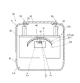
図2は図1のII-II線に平行な水平断面を概略的に示す図であり、図3は図1のIII-III線に平行な鉛直断面を概略的に示す図である。すなわち、図2は灯具1aの上部における水平方向の断面図であり、図3は灯具1aの左右方向の略中央における鉛直方向の断面図である。図2、図3に示すように車両用前照灯1の一部である灯具1aは、筐体10と、当該筐体10内に収容される灯具ユニットLUaとを備える。
FIG. 2 is a diagram schematically showing a horizontal cross section parallel to the line II-II of FIG. 1, and FIG. 3 is a diagram schematically showing a vertical cross section parallel to the line III-III of FIG. That is, FIG. 2 is a horizontal sectional view of the upper part of the
筐体10は、ランプハウジング11、フロントカバー12及びバックカバー13を主な構成として備える。ランプハウジング11の前方は開口しており、当該開口を塞ぐようにフロントカバー12がランプハウジング11に固定されている。また、ランプハウジング11の後方には前方よりも小さな開口が形成されており、当該開口を塞ぐようにバックカバー13がランプハウジング11に固定されている。
The
ランプハウジング11と、当該ランプハウジング11の前方の開口を塞ぐフロントカバー12と、当該ランプハウジング11の後方の開口を塞ぐバックカバー13とによって形成される空間は灯室LRであり、この灯室LR内に灯具ユニットLUaが収容されている。
The space formed by the
灯具ユニットLUaは、リフレクタ20、支持部材30、光源支持基板40、及び光源41を主な構成として備える。
The lamp unit LUa includes a
支持部材30は金属製の部材であり、トッププレート31と、バックプレート32と、係止部33とを有する。トッププレート31は概ね水平に延在する板状の金属部材であり、バックプレート32は概ね鉛直に延在する板状の金属部材である。トッププレート31の後端とバックプレート32の上端は互いに接続されている。また、バックプレート32の上端近傍には、係止部33が接続されている。係止部33はバックプレート32から後方に向かって延在しており、係止部33には後方側に開口するねじ孔が形成されている。このねじ孔にはランプハウジング11の外側からねじ35が螺入され、係止部33がランプハウジング11に固定されている。また、バックプレート32の下方側にもねじ孔が形成されており、このねじ孔にはランプハウジング11の外側からねじ34が螺入されバックプレート32はランプハウジング11に固定されている。こうしてバックプレート32は、概ね鉛直な状態で灯室LR内に固定され、バックプレート32に接続されるトッププレート31も灯室LR内に固定されている。なお、これらのねじ34,35が調整されることで、バックプレート32の角度を微調整することができ、これに伴いトッププレート31の角度を微調整することができる。
The
リフレクタ20は、トッププレート31の下面に固定されている。リフレクタ20はリフレクタ本体部24及びめっき部23を有する。リフレクタ本体部24は樹脂から成る。めっき部23は、リフレクタ本体部24の前方側の面上において、アルミニウム等の金属や金属酸化物によって構成される薄膜である。このめっき部23の表面は、光の反射面23rとされる。反射面23rは、例えば、開口方向が前方側とされる放物線を基調とする自由曲面から成る凹状の形状とされる。より具体的には、反射面23rの鉛直方向の断面における形状は、概ね放物線の中心軸を水平にする場合の頂点よりも下側の形状とされ、反射面23rの水平方向の断面における形状は、概ね放物線の頂点を含む形状とされる。ただし、反射面23rの鉛直方向の断面における放物線と、水平方向の断面における放物線とは互いに異なる放物線とされても良い。また、水平方向の断面における反射面23rの形状は、放物線を基調としなくても良く、例えば楕円の一部を基調とする形状や他の凹状の形状とされても良い。
The
また、トッププレート31の下面には、光源支持基板40が配置され、光源支持基板40には光源41が実装される。本実施形態の灯具ユニットLUaは、左右方向に並んで配置される2つの光源41を備える。ただし、光源41の数は特に限定されず、1つでも3つ以上でも良い。本実施形態の光源41は、ロービームまたはハイビームの一部となる光を出射する。
A light
図4は、図2に示す光源41を拡大して示す平面図であり、図5は、図4に示すV-V線における光源41の鉛直方向の断面図である。図4及び図5に示すように、本実施形態の光源41は、基板42、基板42上に配置されるLEDチップ43、LEDチップ43の発光面43L上に配置される蛍光体44、保護素子45、反射材46、封止樹脂47、端子51,52、及びグランド端子53を有する。
FIG. 4 is an enlarged plan view of the
基板42は、LEDチップ43と及びLEDチップ43を過電流から保護する保護素子45とに電気的に接続される端子51,52及びグランド端子53が一体となった基板である。1つの基板42上には、1つのLEDチップ43が配置される。
The
LEDチップ43は、金バンプ54を介して端子51に電気的に接続され、金バンプ56を介してグランド端子53に電気的に接続される。保護素子45は、金バンプ55を介して端子52に電気的に接続され、金バンプ57を介してグランド端子53に電気的に接続される。また、端子51と端子52とは、不図示の回路等によって電気的に並列に接続されている。LEDチップ43は、端子51を介して給電され、発光する。また、LEDチップ43は反射材46に囲われており、LEDチップ43が発する光は効率良く蛍光体44に入射し得る。光源41において、後述する蛍光体44の出射面41Lを除いて、基板42上の部材は封止樹脂47によって覆われている。封止樹脂47は、例えば白色のシリコーン樹脂からなる。
The
LEDチップ43は一つの発光面43Lを有し、発光面43Lは1つの蛍光体44によって覆われる。発光面43Lから出射する光の少なくとも一部は、蛍光体44に入射し、蛍光体44の出射面41Lから出射する。よって、蛍光体44の出射面41Lは、光源41の発光面である。LEDチップ43から出射する光が上記のように蛍光体44を透過することによって、光源41は所望の色の光を出射する。
The
蛍光体44は上記のようにLEDチップ43の発光面43Lを覆い、蛍光体44のLEDチップ43側とは反対側の面は、発光面43Lからの光が出射する出射面41Lとされる。図4に示すように、蛍光体44の出射面41L、すなわち光源41の発光面は長方形である。なお、図4において、蛍光体44に隠されているLEDチップ43の発光面43Lが破線で示されている。図4に表れる光源41の正面視において、LEDチップ43の発光面43Lの中心と蛍光体44の出射面41Lの中心とが重なる。また、図4に示すように、蛍光体44の出射面41Lの左右方向の大きさはLEDチップ43の発光面43Lの左右方向の大きさより大きく、蛍光体44の出射面41Lの上下方向の大きさはLEDチップ43の発光面43Lの上下方向の大きさより小さい。
As described above, the
蛍光体44の出射面41Lは、第1方向の大きさd1が第2方向の大きさd2より小さい長方形である。第1方向の大きさd1は、例えば0.95mmとされ、第2方向の大きさd2は、例えば1.15mmとされる。また、互いに隣り合う蛍光体44の出射面41L同士の間隔dsは、例えば0.6mmとされる。
The
このような構成の光源41の発光面の第1方向の大きさd1は、光源41からの光による配光パターンの上下方向の広がりに対応する。すなわち、光源41の発光面の第2方向の大きさd2を変えずに第1方向の大きさd1がより大きくされる場合、光源41からの光による配光パターンは、左右方向よりも上下方向により広がる。図3に示すように、光源41の発光面の中心から出射する光L1は、リフレクタ20の反射面23rによって反射され、所望の位置に照射される。光源41の発光面の第1方向の一方の端である発光面の前方端から出射する光Lcは、リフレクタ20の反射面23rによって反射され、光L1が照射される位置よりも上方に照射される。光源41の発光面の第1方向の他方の端である発光面の後方端から出射する光Ldは、リフレクタ20の反射面23rによって反射され、光L1が照射される位置よりも下方に照射される。このように、光源41の発光面の第1方向の大きさd1が大きくなる程、光Lcが照射される位置と光Ldが照射される位置との差Bが大きくなり、配光パターンにぼけが生じ易くなる。
The size d1 of the light emitting surface of the
光源41の発光面の第2方向の大きさd2は、光源41からの光による配光パターンの左右方向の広がりに対応する。すなわち、光源41の発光面の第1方向の大きさd1の大きさを変えずに第2方向の大きさd2がより大きくされる場合、光源41からの光による配光パターンは、上下方向よりも左右方向により広がる。図2に示すように、光源41の発光面の第2方向の一方の端である左端から出射する光Laは、リフレクタ20の反射面23rによって反射され、光源41の発光面の中心から出射する光よりも左方に照射される。光源41の発光面の第2方向の他方の端である右端から出射する光Lbは、リフレクタ20の反射面23rによって反射され、光源41の発光面の中心から出射する光よりも左方に照射される。
The size d2 of the light emitting surface of the
上記のように、本実施形態の光源41において、光源41の発光面の第1方向は車両100の前後方向であり、光源41の発光面の第2方向は車両100の左右方向である。
As described above, in the
上記のような光源41は、それぞれ光源支持基板40に実装され、光源支持基板40に設けられる不図示の発光制御回路に接続されている。また、それぞれの光源41は、光源支持基板40に設けられる発光制御回路からの給電により光を出射することができる。よって、それぞれの光源41は、発光制御回路によって点灯または消灯の制御がなされる。
Each of the
次に本実施形態の車両用前照灯1の動作及び作用効果について説明する。
Next, the operation and operation / effect of the
光源41の位置や反射面23rの形状等が調整されることによって、本実施形態の灯具1aは、ロービーム用の灯具またはハイビーム用の灯具とされる。
By adjusting the position of the
灯具1aがロービーム用の灯具とされる場合、光源41からの光L1により、図6(A)に示すロービームの配光パターンの一部が形成される。図3に示すように、光源41から出射する光L1の多くは反射面23rで反射され、光L1は反射面23rで反射された後にロービームのカットラインより下方に照射される。なお、この場合、車両100の左右に備えられる灯具1aによって、ロービームの配光パターンの少なくとも一部が形成される。
When the
一方、灯具1aがハイビーム用の灯具とされる場合、光源41からの光L1により、図6(B)に示すハイビームの配光パターンの一部が形成される。図3に示すように、光源41から出射する光L1の多くは反射面23rで反射され、ハイビームの配光パターンの一部が形成される。なお、この場合、車両100の左右に備えられる灯具1aによって、ハイビームの配光パターンの少なくとも一部が形成される。
On the other hand, when the
以上説明したように、本実施形態の車両用前照灯1は、基板42と、基板42上に配置されるLEDチップ43と、LEDチップ43の発光面43L上に配置され、発光面43Lから出射する光が透過する蛍光体44と、を有する光源41を備える。1つの基板42上には、1つのLEDチップ43が配置される。また、蛍光体44は、LEDチップ43の発光面43Lからの光が透過して出射する出射面41Lを有し、出射面41Lの第1方向は、出射面41Lから出射する光による配光パターンの上下方向に対応し、出射面41Lの第1方向に垂直な第2方向は、配光パターンの上下方向よりも左右方向の広がりに対応し、出射面41Lの第1方向の大きさd1は出射面41Lの第2方向の大きさd2より小さい。
As described above, the
本実施形態の車両用前照灯1では、LEDチップ43からの光が蛍光体44を透過し、蛍光体44の出射面41Lから出射する。よって、蛍光体44の出射面41Lは、光源41の発光面と言える。光源41からの光による配光パターンの上下方向の広がりに対応する光源41の発光面の第1方向の大きさd1は、配光パターンの左右方向の広がりに対応する光源41の発光面の第2方向の大きさd2より小さい。よって、光源41から出射する光による配光パターンにおいて、上下方向への意図しない光の広がりを抑制しつつ、左右方向への十分な光の広がりを確保し得る。上下方向への意図しない光の広がりが抑制されることによって、配光パターンのぼけが抑制され得る。
In the
また、1つの基板42上に1つのLEDチップ43が配置されることによって、複数のLEDチップ43を用いる場合に互いに隣り合うLEDチップ43間における熱の伝達が抑制され得る。さらに、1つの基板42上に1つのLEDチップ43が配置されることによって、複数のLEDチップ43を用いる場合にそれぞれのLEDチップ43の設置場所の自由度が増し、所望の配光パターンを形成し易くなる。
Further, by arranging one
また、本実施形態の車両用前照灯1では、灯具1aが複数の光源41を備え、複数の光源41が第2方向に沿って並べられる。複数の光源41が第2方向に沿って並べられることによって、上下方向への意図しない光の広がりを抑制しつつ左右方向に所定の広がりを有する配光パターンを形成し易くなる。また、それぞれの光源41の発光面の第2方向の大きさd2は第1方向の大きさd1より大きいため、所定の範囲において複数の光源41が第2方向に沿って並べられる場合、光源41の発光面の面積に対する互いに隣り合う光源41の発光面同士の間隔dsの割合は、光源41の発光面が正方形である場合に比べて小さくなる。そのため、互いに隣り合う光源41から出射する光は互いに重なり易くなり、配光パターンにムラが生じることが抑制され得る。
Further, in the
また、本実施形態の車両用前照灯1において、LEDチップ43の発光面43Lは正方形である。LEDチップ43の発光面43Lが正方形とされることによって、一般的な車両用前照灯に使用されるLEDチップを利用し得る。
Further, in the
また、光源41の正面視において、LEDチップ43の発光面43Lの中心と蛍光体44の出射面41Lの中心とが重なる。光源41の光軸に沿って光源41の発光面を見る場合において、LEDチップ43の発光面43Lの中心と蛍光体44の出射面41Lの中心とが重なるようにLEDチップ43及び蛍光体44が配置されることによって、LEDチップ43が発する光は蛍光体44に入射して透過し易くなる。また、蛍光体44の出射面41Lの第2方向の大きさd2はLEDチップ43の発光面43Lの第2方向の大きさより大きく、出射面41Lの第1方向の大きさd1は発光面43Lの第1方向の大きさより小さい。そのため、光源41から出射する光による配光パターンにおいて、左右方向への十分な光の広がりを確保しつつ、上下方向への光の広がりを抑制し易くなる。
Further, in the front view of the
(第2実施形態)
次に、本発明の第2実施形態について図面を参照して詳細に説明する。なお、第1実施形態と同一または同等の構成要素については、特に説明する場合を除き、同一の参照符号を付して重複する説明は省略する。
(Second Embodiment)
Next, the second embodiment of the present invention will be described in detail with reference to the drawings. The same or equivalent components as those in the first embodiment are designated by the same reference numerals and duplicated description will be omitted unless otherwise specified.
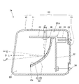
図7は、本発明の第2実施形態における灯具の鉛直方向の断面を概略的に示す図である。すなわち、図7は、図3と同様の視点で本実施形態にかかる灯具1aの断面を示す図である。
FIG. 7 is a diagram schematically showing a vertical cross section of a lamp according to a second embodiment of the present invention. That is, FIG. 7 is a diagram showing a cross section of the
本実施形態の灯具1aが備える灯具ユニットLUaは、プロジェクタ型の灯具ユニットである点において、上記第1実施形態の灯具ユニットLUaと主に異なる。また、本実施形態の灯具1b及び灯具1cは、それぞれ灯具1aと同じ構成とされても良く、異なる構成とされても良い。
The lamp unit LUa included in the
本実施形態の灯具ユニットLUaは、投影レンズ60、レンズホルダ61、光源41、ベース部材62、回動機構63を備える。
The lamp unit LUa of the present embodiment includes a
投影レンズ60は、前面が凸面で後面が平面の平凸非球面レンズである。投影レンズ60は、後側焦点を含む焦点面である後側焦点面上に形成される光源像を、反転像として灯具1aの前方の仮想鉛直上に投影する。また、投影レンズ60は外周部にフランジを有しており、このフランジがレンズホルダ61に固定されている。
The
光源41は、図8には1つのみ表れているが、複数備えられる。図8は、本実施形態の灯具ユニットLUaが備える複数の光源41を正面、すなわち投影レンズ60側から見る図である。図8に示すように、本実施形態の灯具ユニットLUaは、7つの光源41を備える。ただし、光源41の数は特に限定されない。
Although only one
複数の光源41は、投影レンズ60の後側焦点よりも後方において、左右方向に並列して配置される。本実施形態において、複数の光源41は、投影レンズ60の光軸と重なる位置を中心にして左右方向に等間隔で配置される。これらの光源41から出射して投影レンズ60へ向かう光は、投影レンズ60の後側焦点面をある程度の拡がりをもって通過する。このとき、互いに隣り合う光源41から出射する光は、互いに一部が重なる。
The plurality of
また、本実施形態の複数の光源41は、個別に明るさの調整や点灯または消灯の制御が成されるように構成されている。例えば、複数の光源41はそれぞれ不図示の電子制御ユニット(ECU)に接続されており、この電子制御ユニットからの信号によって、それぞれの光源41は、車両の走行状況に応じて明るさの調整や点灯または消灯の制御が個別に行われる。
Further, the plurality of
ベース部材62は、レンズホルダ61および光源支持基板40を支持する部材である。また、ベース部材62は回動機構63に支持される。
The
回動機構63は、ベース部材62を回動する機構を有する部材である。ベース部材62が回動することによって光源41及び投影レンズ60も回動するため、灯具ユニットLUaからの光の照射方向が変更される。また、回動機構63は不図示のECU接続されており、車両の走行状況に応じたECUからの信号によって回動機構63による上記回動が行われ、灯具ユニットLUaからの光の照射方向が調整される。
The
次に本実施形態の車両用前照灯1の動作及び作用効果について説明する。
Next, the operation and operation / effect of the
光源41の位置や投影レンズ60の形状等が調整されることによって、本実施形態の灯具1aは、ロービーム用の灯具またはハイビーム用の灯具とされる。すなわち、図8に示すように、光源41から出射する光L1は、投影レンズ60を透過することで照射方向を調整され、図6(A)に示すロービームの配光パターンの一部、または、図6(B)に示すハイビームの配光パターンの一部を形成する。
By adjusting the position of the
このように光源41からの光が投影レンズ60を透過して照射される場合においても、上記第1実施形態のようにリフレクタが用いられる場合と同様に、光源41の第1方向の大きさd1が大きくなると配光パターンのぼけが生じ易くなる。本実施形態の灯具ユニットLUaでも、配光パターンの上下方向の広がりに対応する光源41の発光面の第1方向の大きさd1は、配光パターンの左右方向の広がりに対応する光源41の発光面の第2方向の大きさd2より小さい。よって、光源41から出射する光L1による配光パターンにおいて、上下方向への意図しない光の広がりを抑制しつつ、左右方向への十分な光の広がりを確保し得る。上下方向への意図しない光の広がりが抑制されることによって、配光パターンのぼけが抑制され得る。
Even when the light from the
また、本実施形態において、それぞれの光源41は、上記のように不図示のECUからの信号によって、明るさの調整や点灯または消灯の制御が個別に行われる。よって、本実施形態の灯具1aを備える車両用前照灯1は、ADB(Adaptive Driving Beam:配光可変ヘッドランプ)等に好適である。
Further, in the present embodiment, each
以上、本発明について実施形態を例に説明したが、本発明はこれらの実施形態に限定されるものではない。 Although the present invention has been described above by exemplifying embodiments, the present invention is not limited to these embodiments.
例えば、光源41の数及び配置は特に限定されない。光源41の数は、1つであっても複数であってもよい。光源41の数及び配置は、灯具1aに求められる機能によって適宜選択され得る。また、1つの灯具1aがハイビーム用の灯具及びロービームの灯具を兼ねるように構成されてもよい。
For example, the number and arrangement of the
また、LEDチップ43の発光面43Lの正面視における形状は正方形に限定されない。例えば、LEDチップ43の発光面43Lの正面視における形状は、出射面41Lと同じ形状や出射面41Lの相似形であってもよい。
Further, the shape of the
また、灯具の数は特に限定されない。灯具が複数備えられる場合、各灯具の位置は特に限定されない。したがって、例えば、上記実施形態において、灯具1aが車両100の最も中心側に配置されても良い。
Further, the number of lamps is not particularly limited. When a plurality of lamps are provided, the position of each lamp is not particularly limited. Therefore, for example, in the above embodiment, the
また、上記第1実施形態では、光源41の下方にリフレクタ20が配置される形態を例示して説明したが、リフレクタ20は、光源41の上方に設けられてもよい。
Further, in the first embodiment, the embodiment in which the
また、本発明は、上記実施形態に限定されず、リフレクタまたはレンズを通して光を照射するいずれの車両用前照灯にも適用可能である。 Further, the present invention is not limited to the above embodiment, and can be applied to any vehicle headlight that irradiates light through a reflector or a lens.
以上説明したように、本発明によれば、配光パターンのぼけを抑制し得る車両用前照灯を提供することができる。当該車両用前照灯は、自動車等の車両用前照灯の分野などにおいて利用可能である。 As described above, according to the present invention, it is possible to provide a vehicle headlight capable of suppressing blurring of a light distribution pattern. The vehicle headlights can be used in the field of vehicle headlights such as automobiles.
1・・・車両用前照灯
1a,1b,1c・・・灯具
10・・・筐体
20・・・リフレクタ
41・・・光源
41L・・・出射面
42・・・基板
43・・・LEDチップ
43L・・・発光面
44・・・蛍光体
45・・・保護素子
51,52・・・端子
53・・・グランド端子
60・・・投影レンズ
LUa・・・灯具ユニット
1 ...
Claims (5)
前記基板上に配置される発光ダイオードチップと、
前記発光ダイオードチップの発光面上に配置され、前記発光面から出射する光が透過する蛍光体と、
を有する光源を備え、
1つの前記基板上に1つの前記発光ダイオードチップが配置され、
前記蛍光体は、前記発光面からの光が透過して出射する出射面を有し、
前記出射面の第1方向は、前記出射面から出射する光による配光パターンの上下方向に対応し、
前記出射面の前記第1方向に垂直な第2方向は、前記配光パターンの上下方向よりも左右方向の広がりに対応し、
前記出射面の前記第1方向の大きさは前記出射面の前記第2方向の大きさ及び前記発光面の前記第1方向の大きさより小さく、
前記出射面の前記第2方向の大きさは前記発光面の前記第2方向の大きさより大きい
ことを特徴とする車両用前照灯。 With the board
A light emitting diode chip arranged on the substrate and
A phosphor arranged on the light emitting surface of the light emitting diode chip and transmitting light emitted from the light emitting surface, and
Equipped with a light source with
One light emitting diode chip is arranged on one substrate, and the light emitting diode chip is arranged.
The phosphor has an exit surface through which light from the light emitting surface is transmitted and emitted.
The first direction of the emission surface corresponds to the vertical direction of the light distribution pattern by the light emitted from the emission surface.
The second direction perpendicular to the first direction of the emission surface corresponds to the spread in the left-right direction rather than the up-down direction of the light distribution pattern.
The size of the emission surface in the first direction is smaller than the size of the emission surface in the second direction and the size of the light emitting surface in the first direction .
The size of the emission surface in the second direction is larger than the size of the light emitting surface in the second direction.
A headlight for vehicles that is characterized by that.
複数の前記光源が前記第2方向に沿って並べられる
ことを特徴とする請求項1に記載の車両用前照灯。 Equipped with multiple light sources
The vehicle headlight according to claim 1, wherein a plurality of the light sources are arranged along the second direction.
ことを特徴とする請求項2に記載の車両用前照灯。 The vehicle headlight according to claim 2, wherein each of the light sources is individually turned on or off.
ことを特徴とする請求項1から3のいずれか1項に記載の車両用前照灯。 The vehicle headlight according to any one of claims 1 to 3, wherein the light emitting surface of the light emitting diode chip is square.
ことを特徴とする請求項1から4のいずれか1項に記載の車両用前照灯。 The vehicle according to any one of claims 1 to 4 , wherein the center of the light emitting surface of the light emitting diode chip and the center of the emitting surface of the phosphor overlap with each other in the front view of the light source. Headlight.
Priority Applications (7)
| Application Number | Priority Date | Filing Date | Title |
|---|---|---|---|
| JP2018122030A JP7101547B2 (en) | 2018-06-27 | 2018-06-27 | Vehicle headlights |
| DE102019209129.6A DE102019209129A1 (en) | 2018-06-27 | 2019-06-25 | Headlights for a vehicle |
| FR1906904A FR3083294B1 (en) | 2018-06-27 | 2019-06-25 | HEADLIGHT FOR A VEHICLE |
| CN201910558916.1A CN110645539A (en) | 2018-06-27 | 2019-06-26 | Vehicle headlamps |
| US16/452,822 US11022263B2 (en) | 2018-06-27 | 2019-06-26 | Headlight for vehicle |
| CN201920969314.0U CN209926250U (en) | 2018-06-27 | 2019-06-26 | Head lamp for vehicle |
| JP2022107502A JP7285362B2 (en) | 2018-06-27 | 2022-07-04 | vehicle headlight |
Applications Claiming Priority (1)
| Application Number | Priority Date | Filing Date | Title |
|---|---|---|---|
| JP2018122030A JP7101547B2 (en) | 2018-06-27 | 2018-06-27 | Vehicle headlights |
Related Child Applications (1)
| Application Number | Title | Priority Date | Filing Date |
|---|---|---|---|
| JP2022107502A Division JP7285362B2 (en) | 2018-06-27 | 2022-07-04 | vehicle headlight |
Publications (2)
| Publication Number | Publication Date |
|---|---|
| JP2020004585A JP2020004585A (en) | 2020-01-09 |
| JP7101547B2 true JP7101547B2 (en) | 2022-07-15 |
Family
ID=68886372
Family Applications (1)
| Application Number | Title | Priority Date | Filing Date |
|---|---|---|---|
| JP2018122030A Active JP7101547B2 (en) | 2018-06-27 | 2018-06-27 | Vehicle headlights |
Country Status (5)
| Country | Link |
|---|---|
| US (1) | US11022263B2 (en) |
| JP (1) | JP7101547B2 (en) |
| CN (2) | CN209926250U (en) |
| DE (1) | DE102019209129A1 (en) |
| FR (1) | FR3083294B1 (en) |
Families Citing this family (2)
| Publication number | Priority date | Publication date | Assignee | Title |
|---|---|---|---|---|
| JP2023161470A (en) * | 2022-04-25 | 2023-11-07 | 市光工業株式会社 | Light-emitting elements for vehicles, light-emitting element packages for vehicles, light source units for vehicles, lamp units for vehicles, lamps for vehicles |
| WO2025182833A1 (en) * | 2024-02-28 | 2025-09-04 | 株式会社小糸製作所 | Vehicle headlight |
Citations (2)
| Publication number | Priority date | Publication date | Assignee | Title |
|---|---|---|---|---|
| JP2013197439A (en) | 2012-03-22 | 2013-09-30 | Koito Mfg Co Ltd | Light-emitting module and vehicular lighting tool |
| JP2016510177A (en) | 2013-03-12 | 2016-04-04 | オスラム オプト セミコンダクターズ ゲゼルシャフト ミット ベシュレンクテル ハフツングOsram Opto Semiconductors GmbH | Optoelectronic parts |
Family Cites Families (12)
| Publication number | Priority date | Publication date | Assignee | Title |
|---|---|---|---|---|
| JP4402425B2 (en) * | 2003-10-24 | 2010-01-20 | スタンレー電気株式会社 | Vehicle headlamp |
| JP4599111B2 (en) * | 2004-07-30 | 2010-12-15 | スタンレー電気株式会社 | LED lamp for lamp light source |
| EP2067176B1 (en) * | 2006-08-09 | 2015-04-01 | Panasonic Corporation | Light-emitting diode |
| JP5518533B2 (en) * | 2010-03-12 | 2014-06-11 | 株式会社小糸製作所 | Vehicle headlamp and light emitting module for vehicle headlamp |
| JP2011204376A (en) * | 2010-03-24 | 2011-10-13 | Stanley Electric Co Ltd | Semiconductor light-emitting device |
| JP5647028B2 (en) * | 2011-02-14 | 2014-12-24 | スタンレー電気株式会社 | Light emitting device and manufacturing method thereof |
| JP5722702B2 (en) | 2011-05-19 | 2015-05-27 | スタンレー電気株式会社 | Vehicle lighting |
| JP5801731B2 (en) * | 2012-01-24 | 2015-10-28 | 株式会社小糸製作所 | Vehicle headlamp |
| WO2013136709A1 (en) * | 2012-03-15 | 2013-09-19 | 株式会社小糸製作所 | Light-emitting device and lighting apparatus for vehicle |
| JP6045834B2 (en) * | 2012-07-23 | 2016-12-14 | ライト プレスクリプションズ イノベーターズ エルエルシー | Vehicle headlamp |
| CN208735539U (en) * | 2017-10-06 | 2019-04-12 | 株式会社小糸制作所 | Headlight for automobile |
| JP6955418B2 (en) * | 2017-10-13 | 2021-10-27 | 株式会社小糸製作所 | Vehicle lighting |
-
2018
- 2018-06-27 JP JP2018122030A patent/JP7101547B2/en active Active
-
2019
- 2019-06-25 DE DE102019209129.6A patent/DE102019209129A1/en active Pending
- 2019-06-25 FR FR1906904A patent/FR3083294B1/en active Active
- 2019-06-26 CN CN201920969314.0U patent/CN209926250U/en active Active
- 2019-06-26 CN CN201910558916.1A patent/CN110645539A/en active Pending
- 2019-06-26 US US16/452,822 patent/US11022263B2/en active Active
Patent Citations (2)
| Publication number | Priority date | Publication date | Assignee | Title |
|---|---|---|---|---|
| JP2013197439A (en) | 2012-03-22 | 2013-09-30 | Koito Mfg Co Ltd | Light-emitting module and vehicular lighting tool |
| JP2016510177A (en) | 2013-03-12 | 2016-04-04 | オスラム オプト セミコンダクターズ ゲゼルシャフト ミット ベシュレンクテル ハフツングOsram Opto Semiconductors GmbH | Optoelectronic parts |
Also Published As
| Publication number | Publication date |
|---|---|
| FR3083294A1 (en) | 2020-01-03 |
| FR3083294B1 (en) | 2021-12-17 |
| DE102019209129A1 (en) | 2020-01-02 |
| US20200003380A1 (en) | 2020-01-02 |
| US11022263B2 (en) | 2021-06-01 |
| CN209926250U (en) | 2020-01-10 |
| JP2020004585A (en) | 2020-01-09 |
| CN110645539A (en) | 2020-01-03 |
Similar Documents
| Publication | Publication Date | Title |
|---|---|---|
| KR100544077B1 (en) | Vehicular headlamp | |
| US10415779B2 (en) | Vehicle headlight | |
| US8616742B2 (en) | Vehicle lighting unit | |
| US8690405B2 (en) | Vehicle lighting unit | |
| US8511874B2 (en) | Vehicle lamp | |
| CN105546447B (en) | Headlight for automobile | |
| US7237935B2 (en) | Light source module and vehicular lamp | |
| CN103216777B (en) | Headlight for automobile | |
| CN103727475A (en) | Vehicular headlamp | |
| WO2022065162A1 (en) | Vehicle lighting fixture | |
| EP2570715A2 (en) | Vehicle headlamp | |
| US12553585B2 (en) | Vehicle lamp | |
| JP7101547B2 (en) | Vehicle headlights | |
| JP2010282790A (en) | Vehicle lighting | |
| JP7081261B2 (en) | Vehicle lighting | |
| JP7285362B2 (en) | vehicle headlight | |
| WO2023189597A1 (en) | Vehicle lamp | |
| TWI601908B (en) | Projection headlights | |
| WO2025115768A1 (en) | Vehicle lamp | |
| WO2023162906A1 (en) | Vehicle lamp | |
| WO2022210913A1 (en) | Lamp unit | |
| JP2024075999A (en) | Vehicle lighting fixtures | |
| JP2026006589A (en) | Vehicle lighting fixtures | |
| WO2025164424A1 (en) | Vehicle lamp | |
| JP2024103206A (en) | Vehicle lighting fixtures |
Legal Events
| Date | Code | Title | Description |
|---|---|---|---|
| A621 | Written request for application examination |
Free format text: JAPANESE INTERMEDIATE CODE: A621 Effective date: 20210511 |
|
| A977 | Report on retrieval |
Free format text: JAPANESE INTERMEDIATE CODE: A971007 Effective date: 20220324 |
|
| A131 | Notification of reasons for refusal |
Free format text: JAPANESE INTERMEDIATE CODE: A131 Effective date: 20220329 |
|
| A521 | Request for written amendment filed |
Free format text: JAPANESE INTERMEDIATE CODE: A523 Effective date: 20220525 |
|
| TRDD | Decision of grant or rejection written | ||
| A01 | Written decision to grant a patent or to grant a registration (utility model) |
Free format text: JAPANESE INTERMEDIATE CODE: A01 Effective date: 20220607 |
|
| A61 | First payment of annual fees (during grant procedure) |
Free format text: JAPANESE INTERMEDIATE CODE: A61 Effective date: 20220705 |
|
| R150 | Certificate of patent or registration of utility model |
Ref document number: 7101547 Country of ref document: JP Free format text: JAPANESE INTERMEDIATE CODE: R150 |