JP4376785B2 - 光走査装置 - Google Patents
光走査装置 Download PDFInfo
- Publication number
- JP4376785B2 JP4376785B2 JP2004537402A JP2004537402A JP4376785B2 JP 4376785 B2 JP4376785 B2 JP 4376785B2 JP 2004537402 A JP2004537402 A JP 2004537402A JP 2004537402 A JP2004537402 A JP 2004537402A JP 4376785 B2 JP4376785 B2 JP 4376785B2
- Authority
- JP
- Japan
- Prior art keywords
- mode
- optical
- radiation beam
- scanning
- power switch
- Prior art date
- Legal status (The legal status is an assumption and is not a legal conclusion. Google has not performed a legal analysis and makes no representation as to the accuracy of the status listed.)
- Expired - Lifetime
Links
Images


Classifications
-
- G—PHYSICS
- G11—INFORMATION STORAGE
- G11B—INFORMATION STORAGE BASED ON RELATIVE MOVEMENT BETWEEN RECORD CARRIER AND TRANSDUCER
- G11B7/00—Recording or reproducing by optical means, e.g. recording using a thermal beam of optical radiation by modifying optical properties or the physical structure, reproducing using an optical beam at lower power by sensing optical properties; Record carriers therefor
- G11B7/12—Heads, e.g. forming of the optical beam spot or modulation of the optical beam
- G11B7/125—Optical beam sources therefor, e.g. laser control circuitry specially adapted for optical storage devices; Modulators, e.g. means for controlling the size or intensity of optical spots or optical traces
- G11B7/126—Circuits, methods or arrangements for laser control or stabilisation
- G11B7/1263—Power control during transducing, e.g. by monitoring
-
- G—PHYSICS
- G02—OPTICS
- G02B—OPTICAL ELEMENTS, SYSTEMS OR APPARATUS
- G02B26/00—Optical devices or arrangements for the control of light using movable or deformable optical elements
- G02B26/004—Optical devices or arrangements for the control of light using movable or deformable optical elements based on a displacement or a deformation of a fluid
- G02B26/005—Optical devices or arrangements for the control of light using movable or deformable optical elements based on a displacement or a deformation of a fluid based on electrowetting
-
- G—PHYSICS
- G02—OPTICS
- G02B—OPTICAL ELEMENTS, SYSTEMS OR APPARATUS
- G02B26/00—Optical devices or arrangements for the control of light using movable or deformable optical elements
- G02B26/02—Optical devices or arrangements for the control of light using movable or deformable optical elements for controlling the intensity of light
-
- G—PHYSICS
- G02—OPTICS
- G02B—OPTICAL ELEMENTS, SYSTEMS OR APPARATUS
- G02B3/00—Simple or compound lenses
- G02B3/12—Fluid-filled or evacuated lenses
- G02B3/14—Fluid-filled or evacuated lenses of variable focal length
-
- G—PHYSICS
- G11—INFORMATION STORAGE
- G11B—INFORMATION STORAGE BASED ON RELATIVE MOVEMENT BETWEEN RECORD CARRIER AND TRANSDUCER
- G11B7/00—Recording or reproducing by optical means, e.g. recording using a thermal beam of optical radiation by modifying optical properties or the physical structure, reproducing using an optical beam at lower power by sensing optical properties; Record carriers therefor
- G11B7/12—Heads, e.g. forming of the optical beam spot or modulation of the optical beam
- G11B7/135—Means for guiding the beam from the source to the record carrier or from the record carrier to the detector
- G11B7/1372—Lenses
- G11B7/1376—Collimator lenses
-
- G—PHYSICS
- G11—INFORMATION STORAGE
- G11B—INFORMATION STORAGE BASED ON RELATIVE MOVEMENT BETWEEN RECORD CARRIER AND TRANSDUCER
- G11B7/00—Recording or reproducing by optical means, e.g. recording using a thermal beam of optical radiation by modifying optical properties or the physical structure, reproducing using an optical beam at lower power by sensing optical properties; Record carriers therefor
- G11B7/12—Heads, e.g. forming of the optical beam spot or modulation of the optical beam
- G11B7/135—Means for guiding the beam from the source to the record carrier or from the record carrier to the detector
- G11B7/1398—Means for shaping the cross-section of the beam, e.g. into circular or elliptical cross-section
Description
前記放射ビームを放射するための放射源と;
前記情報層の位置に走査スポットを形成するために前記放射ビームを収束するための、光軸を有する対物レンズと;
書き込みモードにおける第1光パワーと読み出しモードにおけるより小さい第2光パワーとの間で前記走査スポットの光パワーをスイッチングするための、前記放射ビームの光路に備えられた走査スポットパワースイッチと;
を有する光走査装置に関する。

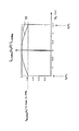
同様に、読み出しモードにおいて、放射ビーム25のいずれのリム光線は、直行座標(x1,y1)の第2ポイントにおいて入射平面20aに入射する放射ビーム17の光線からもたらされ、その第2ポイントとポイントO1との間の距離は、その光線に拘らず、一定である第2距離hreadingに等しい。それ故、読み出しモードにおいて、その第2ポイントの座標(x1,y1)は次式により与えられる。
それ故、式(4a)、(4b)、(5a)及び(5b)から次の式が導き出される。
R1=(d1(n1−n2))/(n1(1−r0/h1)) (7a)
R2=R1+(n1−n2)d1/n1 (7b)
ここで、“h1”は距離hwritingか又はhreadingのどちらかである。
方にそのビームを反射し、それ故、そのビームは、ここでは、偏光p‖を有する。それ故、ビームスプリッタ76は、プレート74により第2ミラー72の方にそのビームを透過する。ミラー72は、次いで、再び、プレート74によりビームスプリッタ76の方にそのビームを反射し、それ故、そのビームは、ここでは、偏光p⊥を有する。それ故、ビームスプリッタ76は、プレート75により対物レンズ10の方にそのビームを反射する。情報層2における反射の後、ビームは、対物レンズ10及びプレート75によりビームスプリッタ76に伝搬し、それ故、ビームは、ここでは、偏光p‖を有する。従って、ビームスプリッタ76は、偏光p‖を有するそのビームを偏光スイッチ70の方に透過する。又、その実施形態であって、書き込みモードにおいて、偏光スイッチ70は偏光p‖から偏光p⊥に変える。それ故、偏光スイッチ70から発生する放射ビームは偏光p⊥を有し、コリメータレンズ8により第1偏光ビームスプリッタに伝搬する。スプリッタ9は検出器24の方にそのビームを反射する。
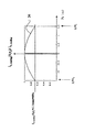
hwriting/hreading=f1/f2 (8)
ここで、“f1”及び“f2”はミラー71及び72それぞれの画像焦点長さである。
Claims (7)
- 書き込みモード及び読み出しモードにおいて放射ビームにより情報層を走査する光走査装置であって:
前記放射ビームを放射する放射源;
前記情報層の位置に走査スポットを形成するように前記放射ビームを収束するために光軸を有する対物レンズ;及び
前記書き込みモードにおける第1光パワーレベルと前記読み出しモードにおけるより低い第2光パワーレベルとの間で前記走査スポットの光パワーをスイッチングするために、前記放射ビームの光路内に備えられている走査スポットパワースイッチ;
を有する光走査装置であり、
前記走査スポットパワースイッチは、前記書き込みモードにおける第1リム強度レベルと前記読み出しモードにおけるより高い第2リム強度レベルとの間で前記放射ビームのリム強度をスイッチングするように、それにより、前記書き込みモードにおける前記第1光パワーレベルと前記読出しモードにおける前記第2光パワーレベルとの間で前記走査スポットの前記光パワーをスイッチングするように、前記書き込みモードにおける第1サイズと前記読み出しモードにおけるより大きい第2サイズとの間で、前記走査スポットパワースイッチの出口から放射される前記放射ビームの断面のサイズをスイッチングするように更に備えられている;
ことを特徴とする光走査装置。 - 請求項1に記載の光走査装置であって、前記放射源と前記走査スポットパワースイッチとの間に備えられているコリメータレンズを更に有し、前記放射ビームの断面が前記書き込みモードにおける前記第1サイズ及び前記読み出しモードにおける前記第2サイズを有するように、前記走査スポットパワースイッチが前記書き込みモードと前記読出しモードとの間のスイッチング可能横倍率を有するテレスコープ状配置を構成する、ことを特徴とする光走査装置。
- 請求項1又は2に記載の光走査装置であって、前記走査スポットパワースイッチは、前記放射ビームの断面が前記書き込みモードにおける前記第1サイズ及び前記読み出しモードにおける前記第2サイズを有するように、電気的に調節可能である形状の第1メニスカス及び第2メニスカスを有する可変焦点液体レンズを有する、ことを特徴とする光走査装置。
- 請求項1又は2に記載の光走査装置であって、前記放射ビームは第1偏光か又は異なる第2偏光のどちらかを有し、前記走査スポットパワースイッチは:
偏光に依存する前記放射ビームを反射及び透過することができる偏光ビームスプリッタ;
前記偏光ビームスプリッタの一の側に備えられている第1ミラー及び前記偏光ビームスプリッタの他の側に備えられている第2ミラー;
前記偏光ビームスプリッタと前記第1ミラーとの間に備えられている第1の1/4波長プレート;
前記偏光ビームスプリッタと前記第2ミラーとの間に備えられている第2の1/4波長プレート;
前記偏光ビームスプリッタと前記対物レンズとの間に備えられている第3の1/4波長プレート;並びに
前記放射ビームの前記断面が前記書き込みモードにおける前記第1サイズ及び前記読み出しモードにおける前記第2サイズを有するように、前記第1偏光と前記第2偏光との間で前記放射ビームの偏光を変えることができる、前記放射ビームの前記光路に備えられている偏光スイッチ;
を有する、ことを特徴とする光走査装置。 - 請求項1乃至4のいずれか一項に記載の光走査装置であって、検出システムが、焦点エラー信号及び/又はラジアルトラッキングエラー信号を供給するように備えられ、走査されるようになっている前記情報層のトラック及び/又は前記情報層の位置に対して前記走査スポットの位置を制御する前記焦点エラー信号及び/又はラジアルトラッキングエラー信号前記に応答するアクチュエータ及びサーボ回路を更に有する、ことを特徴とする光走査装置。
- 請求項5に記載の光走査装置であって、エラー補正のための情報処理ユニットを更に有する、ことを特徴とする光走査装置。
- 書き込みモード及び読出しモードにおいて放射ビームにより光記録担体を走査する光走査装置に適切な走査スポットパワースイッチであって、該走査スポットパワースイッチは、前記書き込みモードにおける第1光パワーレベルと前記読み出しモードにおける低い第2光パワーレベルとの間で走査スポットの光パワーをスイッチングするために備えられていて、前記書き込みモードにおける第1リム強度と前記読み出しモードにおけるより高い第2リム強度との間で前記放射ビームのリム強度をスイッチングするように、それにより、第1モードにおける第1光パワーレベルと第2モードにおける第2光パワーとの間で前記走査スポットの前記光パワーをスイッチングするように、前記書き込みモードにおける第1サイズと前記読み出しモードにおける大きい第2サイズとの間で、前記走査スポットパワースイッチの出口から放射される前記放射ビームの断面のサイズをスイッチングするように更に備えられている、ことを特徴とする走査スポットパワースイッチ。
Applications Claiming Priority (3)
| Application Number | Priority Date | Filing Date | Title |
|---|---|---|---|
| EP02078939 | 2002-09-19 | ||
| EP02080016 | 2002-11-29 | ||
| PCT/IB2003/003935 WO2004027769A1 (en) | 2002-09-19 | 2003-09-12 | Optical scanning device |
Publications (2)
| Publication Number | Publication Date |
|---|---|
| JP2006500710A JP2006500710A (ja) | 2006-01-05 |
| JP4376785B2 true JP4376785B2 (ja) | 2009-12-02 |
Family
ID=32031775
Family Applications (1)
| Application Number | Title | Priority Date | Filing Date |
|---|---|---|---|
| JP2004537402A Expired - Lifetime JP4376785B2 (ja) | 2002-09-19 | 2003-09-12 | 光走査装置 |
Country Status (8)
| Country | Link |
|---|---|
| US (1) | US7170832B2 (ja) |
| EP (1) | EP1543513A1 (ja) |
| JP (1) | JP4376785B2 (ja) |
| KR (1) | KR20050057451A (ja) |
| CN (1) | CN100446098C (ja) |
| AU (1) | AU2003259476A1 (ja) |
| TW (1) | TW200405305A (ja) |
| WO (1) | WO2004027769A1 (ja) |
Families Citing this family (22)
| Publication number | Priority date | Publication date | Assignee | Title |
|---|---|---|---|---|
| US20040213097A1 (en) * | 2003-04-25 | 2004-10-28 | Konica Minolta Opto, Inc. | Optical pick-up device |
| WO2004102253A1 (en) * | 2003-05-14 | 2004-11-25 | Koninklijke Philips Electronics N.V. | Variable shape lens |
| KR101194701B1 (ko) * | 2004-03-04 | 2012-10-31 | 코닌클리케 필립스 일렉트로닉스 엔.브이. | 광 빔에 광학수차를 도입하는 광학 부재 |
| KR20060134127A (ko) * | 2004-03-31 | 2006-12-27 | 코닌클리케 필립스 일렉트로닉스 엔.브이. | 광학 주사 장치 |
| US7121998B1 (en) * | 2004-06-08 | 2006-10-17 | Eurica Califorrniaa | Vented microcradle for prenidial incubator |
| WO2006035348A1 (en) * | 2004-09-28 | 2006-04-06 | Koninklijke Philips Electronics N.V. | Optical scanning device |
| WO2006054215A1 (en) * | 2004-11-16 | 2006-05-26 | Koninklijke Philips Electronics N.V. | Optical head with switchable diameter of the radiation spot on the radiation detector |
| JP2008521044A (ja) * | 2004-11-17 | 2008-06-19 | コーニンクレッカ フィリップス エレクトロニクス エヌ ヴィ | 流体紫外レンズ |
| KR20070089243A (ko) * | 2004-12-21 | 2007-08-30 | 코닌클리즈케 필립스 일렉트로닉스 엔.브이. | 광분포 장치 |
| WO2006070329A2 (en) * | 2004-12-29 | 2006-07-06 | Koninklijke Philips Electronics N.V. | Dual layer readout with improved tolerances |
| US7657182B2 (en) | 2005-08-04 | 2010-02-02 | Panasonic Corporation | Liquid lens optical transmitter system |
| CN101421784B (zh) * | 2006-04-18 | 2011-01-12 | 松下电器产业株式会社 | 光学信息记录再生装置 |
| WO2008097440A2 (en) * | 2007-02-05 | 2008-08-14 | Xtreme Energetics Inc. | Electro-wetting optical light steering |
| US20100019126A1 (en) * | 2007-03-13 | 2010-01-28 | Ryuichi Katayama | Optical head device, optical information recording/reproducing device, and optical information recording/reproducing method thereof |
| US20100060991A1 (en) * | 2008-09-11 | 2010-03-11 | Omnivision Technologies, Inc. | Electrically-Controlled, Variable Focal Length Liquid-Based Optical Imaging Apparatus and Method |
| WO2010084200A1 (de) * | 2009-01-26 | 2010-07-29 | Seereal Technologies S.A. | Einrichtung zur amplitudenmodulation |
| US8659835B2 (en) * | 2009-03-13 | 2014-02-25 | Optotune Ag | Lens systems and method |
| US8699141B2 (en) | 2009-03-13 | 2014-04-15 | Knowles Electronics, Llc | Lens assembly apparatus and method |
| JP2010218608A (ja) * | 2009-03-16 | 2010-09-30 | Hitachi Ltd | 光情報記録再生方法及び装置及び媒体 |
| DE102012204068A1 (de) * | 2012-03-15 | 2013-09-19 | Zumtobel Lighting Gmbh | Leuchte mit im Wesentlichen punktförmiger Lichtquelle und zugeordnetem optischen System |
| CN104655028B (zh) * | 2013-11-22 | 2017-08-22 | 睿励科学仪器(上海)有限公司 | 用于半导体基片测量的聚焦系统与聚焦方法 |
| EP3657503B1 (en) | 2013-11-28 | 2022-05-25 | Shanghai Naguang Information Technology Corporation | Method of optically reading data |
Family Cites Families (23)
| Publication number | Priority date | Publication date | Assignee | Title |
|---|---|---|---|---|
| US4363113A (en) | 1975-02-10 | 1982-12-07 | Seiscom Delta, Inc. | Seismic exploration with simulated plane waves |
| US4307929A (en) | 1979-08-29 | 1981-12-29 | Eveleth Jason H | Method of scanning a laser beam in a straight line |
| EP0156141B1 (en) * | 1984-03-09 | 1992-05-13 | Hitachi, Ltd. | Prism optics and optical information processing apparatus |
| US4737906A (en) | 1985-09-27 | 1988-04-12 | International Business Machines Corporation | Multiple virtual control unit |
| JPH02246030A (ja) * | 1989-03-17 | 1990-10-01 | Ricoh Co Ltd | 光情報記録再生装置 |
| JPH0628672A (ja) * | 1992-06-12 | 1994-02-04 | Senri Oyo Keisoku Kenkyusho:Kk | 光学的データ記憶体並びにこの記録装置及び記録再生装置 |
| JP3488261B2 (ja) * | 1992-07-27 | 2004-01-19 | 三洋電機株式会社 | 光記録媒体の再生方法及び再生装置 |
| DE69332730T2 (de) * | 1992-08-07 | 2003-10-23 | Matsushita Electric Ind Co Ltd | Optisches Speichergerät |
| JPH08102079A (ja) * | 1994-09-30 | 1996-04-16 | Matsushita Electric Ind Co Ltd | 光学ヘッド |
| US5737299A (en) * | 1996-10-18 | 1998-04-07 | Samsung Electronics Co., Ltd. | Optical pickup apparatus having wave plates |
| JP3571168B2 (ja) | 1997-03-28 | 2004-09-29 | 株式会社東芝 | 光ディスク装置 |
| JPH11126363A (ja) * | 1997-10-24 | 1999-05-11 | Sony Corp | 光学式情報記録再生装置 |
| JPH11194207A (ja) * | 1997-12-26 | 1999-07-21 | Fuji Photo Optical Co Ltd | 回折型フィルタ |
| JPH11259895A (ja) | 1998-03-09 | 1999-09-24 | Fuji Electric Co Ltd | 多層記録用光ヘッド |
| JPH11316965A (ja) * | 1998-05-06 | 1999-11-16 | Sony Corp | 光学式情報記録再生装置および方法 |
| JP2000221388A (ja) * | 1999-01-29 | 2000-08-11 | Fuji Photo Optical Co Ltd | 光束径可変型対物レンズおよびこれを用いた光学装置 |
| JP2001307365A (ja) | 2000-04-24 | 2001-11-02 | Toshiba Corp | 光学ヘッド装置、光ディスク装置 |
| JP2001357557A (ja) * | 2001-05-14 | 2001-12-26 | Matsushita Electric Ind Co Ltd | 光学ヘッド |
| JP3794940B2 (ja) * | 2001-06-19 | 2006-07-12 | 株式会社日立製作所 | 対物レンズ光学系、光ヘッド及び光情報再生装置 |
| US6940794B2 (en) * | 2001-08-03 | 2005-09-06 | Matsushita Electric Industrial Co., Ltd. | Information recording/reproducing apparatus that determines the number of recording layers of an information recording medium |
| JP4240883B2 (ja) * | 2001-12-27 | 2009-03-18 | ソニー株式会社 | 光ヘッド及び光記録媒体駆動装置 |
| JP2002267810A (ja) * | 2002-01-21 | 2002-09-18 | Fujitsu Ltd | 光強度変換素子及び光学装置 |
| KR100988705B1 (ko) * | 2002-08-29 | 2010-10-18 | 소니 주식회사 | 광헤드 및 광기록 매체 구동 장치 |
-
2003
- 2003-09-12 EP EP03797445A patent/EP1543513A1/en not_active Withdrawn
- 2003-09-12 AU AU2003259476A patent/AU2003259476A1/en not_active Abandoned
- 2003-09-12 WO PCT/IB2003/003935 patent/WO2004027769A1/en active Application Filing
- 2003-09-12 KR KR1020057004686A patent/KR20050057451A/ko active IP Right Grant
- 2003-09-12 US US10/527,870 patent/US7170832B2/en not_active Expired - Fee Related
- 2003-09-12 CN CNB038221829A patent/CN100446098C/zh not_active Expired - Fee Related
- 2003-09-12 JP JP2004537402A patent/JP4376785B2/ja not_active Expired - Lifetime
- 2003-09-16 TW TW092125485A patent/TW200405305A/zh unknown
Also Published As
| Publication number | Publication date |
|---|---|
| CN100446098C (zh) | 2008-12-24 |
| TW200405305A (en) | 2004-04-01 |
| US20060087711A1 (en) | 2006-04-27 |
| US7170832B2 (en) | 2007-01-30 |
| CN1682294A (zh) | 2005-10-12 |
| KR20050057451A (ko) | 2005-06-16 |
| AU2003259476A1 (en) | 2004-04-08 |
| JP2006500710A (ja) | 2006-01-05 |
| WO2004027769A1 (en) | 2004-04-01 |
| EP1543513A1 (en) | 2005-06-22 |
Similar Documents
| Publication | Publication Date | Title |
|---|---|---|
| JP4376785B2 (ja) | 光走査装置 | |
| US6034797A (en) | Prism-type objective lens for the pickup head of an optical disc drive capable of driving two types of optical discs | |
| KR20070087214A (ko) | 수차 교정장치 | |
| KR20080022186A (ko) | 2개의 메니스커스를 갖는 가변 유체 렌즈 | |
| KR20060134127A (ko) | 광학 주사 장치 | |
| US20080205242A1 (en) | Multi-Radiation Beam Optical Scanning Device | |
| JP2006518906A (ja) | 2つの非混和性流体のインターフェイスによって形成された可変レンズを有する光ディスク記録/再生装置用の対物レンズ | |
| JPH11339310A (ja) | 光ピックアップ装置 | |
| EP1875278A1 (en) | Variable focus lens | |
| JP2005515580A (ja) | 光走査デバイス | |
| EP0824753A1 (en) | Objective lens and scanning device using such an objective lens | |
| JP2006511007A (ja) | 光走査デバイス | |
| JP2009170072A (ja) | 光ピックアップ光学系、これを用いた光ピックアップ装置 | |
| KR20060040678A (ko) | 가변 빔 정형소자 | |
| JP2005535063A (ja) | 2種類の材料で形成された対物レンズを含むスキャン装置 | |
| JP2005535066A (ja) | レンズ保護デバイスを備えた対物系を含む走査デバイス | |
| JP2008546032A (ja) | スイッチング可能光学要素 | |
| JP2005513693A6 (ja) | 光学走査デバイス | |
| JP2005513693A (ja) | 光学走査デバイス | |
| KR20030019961A (ko) | 광 기록 및 재생 시스템용 광학렌즈 | |
| JPH11296889A (ja) | 高開口数光学系、及び光磁気用光学ヘッド | |
| JP2005535067A (ja) | 単独材料で形成された対物レンズ系を含むスキャン装置 | |
| WO2006035348A1 (en) | Optical scanning device | |
| KR20010029132A (ko) | 광디스크 경사 보정장치 및 이를 채용한 광픽업장치 |
Legal Events
| Date | Code | Title | Description |
|---|---|---|---|
| A621 | Written request for application examination |
Free format text: JAPANESE INTERMEDIATE CODE: A621 Effective date: 20060908 |
|
| A977 | Report on retrieval |
Free format text: JAPANESE INTERMEDIATE CODE: A971007 Effective date: 20081226 |
|
| A131 | Notification of reasons for refusal |
Free format text: JAPANESE INTERMEDIATE CODE: A131 Effective date: 20090127 |
|
| A601 | Written request for extension of time |
Free format text: JAPANESE INTERMEDIATE CODE: A601 Effective date: 20090424 |
|
| A602 | Written permission of extension of time |
Free format text: JAPANESE INTERMEDIATE CODE: A602 Effective date: 20090507 |
|
| A521 | Written amendment |
Free format text: JAPANESE INTERMEDIATE CODE: A523 Effective date: 20090717 |
|
| TRDD | Decision of grant or rejection written | ||
| A01 | Written decision to grant a patent or to grant a registration (utility model) |
Free format text: JAPANESE INTERMEDIATE CODE: A01 Effective date: 20090825 |
|
| A01 | Written decision to grant a patent or to grant a registration (utility model) |
Free format text: JAPANESE INTERMEDIATE CODE: A01 |
|
| A61 | First payment of annual fees (during grant procedure) |
Free format text: JAPANESE INTERMEDIATE CODE: A61 Effective date: 20090909 |
|
| R150 | Certificate of patent or registration of utility model |
Free format text: JAPANESE INTERMEDIATE CODE: R150 |
|
| FPAY | Renewal fee payment (event date is renewal date of database) |
Free format text: PAYMENT UNTIL: 20120918 Year of fee payment: 3 |