JP4305649B2 - Axial gap type electric motor - Google Patents
Axial gap type electric motor Download PDFInfo
- Publication number
- JP4305649B2 JP4305649B2 JP2003416651A JP2003416651A JP4305649B2 JP 4305649 B2 JP4305649 B2 JP 4305649B2 JP 2003416651 A JP2003416651 A JP 2003416651A JP 2003416651 A JP2003416651 A JP 2003416651A JP 4305649 B2 JP4305649 B2 JP 4305649B2
- Authority
- JP
- Japan
- Prior art keywords
- axial gap
- electric motor
- type electric
- stator
- gap type
- Prior art date
- Legal status (The legal status is an assumption and is not a legal conclusion. Google has not performed a legal analysis and makes no representation as to the accuracy of the status listed.)
- Expired - Lifetime
Links
- 230000002093 peripheral effect Effects 0.000 claims description 36
- 239000012212 insulator Substances 0.000 claims description 28
- 229920005989 resin Polymers 0.000 claims description 28
- 239000011347 resin Substances 0.000 claims description 28
- 238000004804 winding Methods 0.000 claims description 28
- 229920003002 synthetic resin Polymers 0.000 claims description 10
- 239000000057 synthetic resin Substances 0.000 claims description 10
- 239000011810 insulating material Substances 0.000 claims description 2
- 230000010354 integration Effects 0.000 claims 1
- 238000003860 storage Methods 0.000 description 32
- 238000000034 method Methods 0.000 description 14
- XEEYBQQBJWHFJM-UHFFFAOYSA-N Iron Chemical group [Fe] XEEYBQQBJWHFJM-UHFFFAOYSA-N 0.000 description 12
- 238000000465 moulding Methods 0.000 description 10
- 229910052742 iron Inorganic materials 0.000 description 5
- 229920010524 Syndiotactic polystyrene Polymers 0.000 description 4
- 230000000694 effects Effects 0.000 description 4
- 238000009826 distribution Methods 0.000 description 2
- 235000012489 doughnuts Nutrition 0.000 description 2
- 230000004907 flux Effects 0.000 description 2
- 238000010030 laminating Methods 0.000 description 2
- WABPQHHGFIMREM-UHFFFAOYSA-N lead(0) Chemical compound [Pb] WABPQHHGFIMREM-UHFFFAOYSA-N 0.000 description 2
- 238000004519 manufacturing process Methods 0.000 description 2
- 239000000463 material Substances 0.000 description 2
- 239000000843 powder Substances 0.000 description 2
- 229910000831 Steel Inorganic materials 0.000 description 1
- 230000004323 axial length Effects 0.000 description 1
- 238000006243 chemical reaction Methods 0.000 description 1
- 238000010292 electrical insulation Methods 0.000 description 1
- 238000009499 grossing Methods 0.000 description 1
- 230000002452 interceptive effect Effects 0.000 description 1
- 239000002184 metal Substances 0.000 description 1
- 229910052751 metal Inorganic materials 0.000 description 1
- 238000012986 modification Methods 0.000 description 1
- 230000004048 modification Effects 0.000 description 1
- 238000003825 pressing Methods 0.000 description 1
- 239000010959 steel Substances 0.000 description 1
- 239000011800 void material Substances 0.000 description 1
- 239000002699 waste material Substances 0.000 description 1
Images


Classifications
-
- G—PHYSICS
- G01—MEASURING; TESTING
- G01N—INVESTIGATING OR ANALYSING MATERIALS BY DETERMINING THEIR CHEMICAL OR PHYSICAL PROPERTIES
- G01N33/00—Investigating or analysing materials by specific methods not covered by groups G01N1/00 - G01N31/00
- G01N33/18—Water
-
- H—ELECTRICITY
- H02—GENERATION; CONVERSION OR DISTRIBUTION OF ELECTRIC POWER
- H02K—DYNAMO-ELECTRIC MACHINES
- H02K21/00—Synchronous motors having permanent magnets; Synchronous generators having permanent magnets
- H02K21/12—Synchronous motors having permanent magnets; Synchronous generators having permanent magnets with stationary armatures and rotating magnets
- H02K21/24—Synchronous motors having permanent magnets; Synchronous generators having permanent magnets with stationary armatures and rotating magnets with magnets axially facing the armatures, e.g. hub-type cycle dynamos
-
- G—PHYSICS
- G01—MEASURING; TESTING
- G01N—INVESTIGATING OR ANALYSING MATERIALS BY DETERMINING THEIR CHEMICAL OR PHYSICAL PROPERTIES
- G01N27/00—Investigating or analysing materials by the use of electric, electrochemical, or magnetic means
- G01N27/02—Investigating or analysing materials by the use of electric, electrochemical, or magnetic means by investigating impedance
- G01N27/04—Investigating or analysing materials by the use of electric, electrochemical, or magnetic means by investigating impedance by investigating resistance
- G01N27/06—Investigating or analysing materials by the use of electric, electrochemical, or magnetic means by investigating impedance by investigating resistance of a liquid
-
- G—PHYSICS
- G01—MEASURING; TESTING
- G01N—INVESTIGATING OR ANALYSING MATERIALS BY DETERMINING THEIR CHEMICAL OR PHYSICAL PROPERTIES
- G01N27/00—Investigating or analysing materials by the use of electric, electrochemical, or magnetic means
- G01N27/26—Investigating or analysing materials by the use of electric, electrochemical, or magnetic means by investigating electrochemical variables; by using electrolysis or electrophoresis
- G01N27/416—Systems
- G01N27/4166—Systems measuring a particular property of an electrolyte
- G01N27/4167—Systems measuring a particular property of an electrolyte pH
-
- H—ELECTRICITY
- H02—GENERATION; CONVERSION OR DISTRIBUTION OF ELECTRIC POWER
- H02K—DYNAMO-ELECTRIC MACHINES
- H02K1/00—Details of the magnetic circuit
- H02K1/06—Details of the magnetic circuit characterised by the shape, form or construction
- H02K1/12—Stationary parts of the magnetic circuit
- H02K1/14—Stator cores with salient poles
- H02K1/146—Stator cores with salient poles consisting of a generally annular yoke with salient poles
- H02K1/148—Sectional cores
-
- H—ELECTRICITY
- H02—GENERATION; CONVERSION OR DISTRIBUTION OF ELECTRIC POWER
- H02K—DYNAMO-ELECTRIC MACHINES
- H02K3/00—Details of windings
- H02K3/46—Fastening of windings on the stator or rotor structure
- H02K3/52—Fastening salient pole windings or connections thereto
- H02K3/521—Fastening salient pole windings or connections thereto applicable to stators only
- H02K3/524—Fastening salient pole windings or connections thereto applicable to stators only for U-shaped, E-shaped or similarly shaped cores
-
- H—ELECTRICITY
- H02—GENERATION; CONVERSION OR DISTRIBUTION OF ELECTRIC POWER
- H02K—DYNAMO-ELECTRIC MACHINES
- H02K5/00—Casings; Enclosures; Supports
- H02K5/04—Casings or enclosures characterised by the shape, form or construction thereof
- H02K5/08—Insulating casings
-
- H—ELECTRICITY
- H02—GENERATION; CONVERSION OR DISTRIBUTION OF ELECTRIC POWER
- H02K—DYNAMO-ELECTRIC MACHINES
- H02K7/00—Arrangements for handling mechanical energy structurally associated with dynamo-electric machines, e.g. structural association with mechanical driving motors or auxiliary dynamo-electric machines
- H02K7/08—Structural association with bearings
-
- H—ELECTRICITY
- H02—GENERATION; CONVERSION OR DISTRIBUTION OF ELECTRIC POWER
- H02K—DYNAMO-ELECTRIC MACHINES
- H02K1/00—Details of the magnetic circuit
- H02K1/06—Details of the magnetic circuit characterised by the shape, form or construction
- H02K1/12—Stationary parts of the magnetic circuit
- H02K1/18—Means for mounting or fastening magnetic stationary parts on to, or to, the stator structures
- H02K1/182—Means for mounting or fastening magnetic stationary parts on to, or to, the stator structures to stators axially facing the rotor, i.e. with axial or conical air gap
-
- H—ELECTRICITY
- H02—GENERATION; CONVERSION OR DISTRIBUTION OF ELECTRIC POWER
- H02K—DYNAMO-ELECTRIC MACHINES
- H02K15/00—Methods or apparatus specially adapted for manufacturing, assembling, maintaining or repairing of dynamo-electric machines
- H02K15/08—Forming windings by laying conductors into or around core parts
- H02K15/095—Forming windings by laying conductors into or around core parts by laying conductors around salient poles
-
- H—ELECTRICITY
- H02—GENERATION; CONVERSION OR DISTRIBUTION OF ELECTRIC POWER
- H02K—DYNAMO-ELECTRIC MACHINES
- H02K2203/00—Specific aspects not provided for in the other groups of this subclass relating to the windings
- H02K2203/06—Machines characterised by the wiring leads, i.e. conducting wires for connecting the winding terminations
-
- H—ELECTRICITY
- H02—GENERATION; CONVERSION OR DISTRIBUTION OF ELECTRIC POWER
- H02K—DYNAMO-ELECTRIC MACHINES
- H02K2203/00—Specific aspects not provided for in the other groups of this subclass relating to the windings
- H02K2203/12—Machines characterised by the bobbins for supporting the windings
Description
本発明は、それぞれがほぼ円盤状に形成されており、同一の回転軸に所定の空隙をもって対向的に配置されるステータとロータとを含むアキシャルギャップ型電動機に関し、さらに詳しく言えば、ステータが複数個のポールメンバーにより組み立てられるアキシャルギャップ型電動機に関するものである。 The present invention relates to an axial gap type electric motor including a stator and a rotor, each of which is formed in a substantially disk shape and is opposed to each other with a predetermined gap on the same rotating shaft. The present invention relates to an axial gap type electric motor assembled by individual pole members.
アキシャルギャップ型電動機(軸方向空隙型電動機)は、例えば特許文献1に示すように、円盤状のステータの両側に一対のロータを所定の空隙をもって軸方向に対向配置した電動機であり、ラジアルギャップ型電動機に比べて軸方向長さを短くでき、電動機自体を薄型化し得る利点を備えている。 An axial gap type electric motor (axial gap type electric motor) is an electric motor in which a pair of rotors are arranged opposite to each other in the axial direction with a predetermined gap on both sides of a disk-shaped stator, as shown in Patent Document 1, for example. Compared to the electric motor, the axial length can be shortened, and the electric motor itself can be made thinner.
ところで、従来のアキシャルギャップ型電動機において、ステータは、リング状に形成されたティース(鉄心)の各溝にコイルを巻き付け、その内周部にロータ出力軸に対する軸受部を同軸的に配置し、上記ティースと軸受部とを含む全体を樹脂で一体にモールド成型してなる。 By the way, in the conventional axial gap type electric motor, the stator has a coil wound around each groove of a tooth (iron core) formed in a ring shape, and a bearing portion for the rotor output shaft is coaxially arranged on the inner peripheral portion thereof. The whole including the teeth and the bearing portion is integrally molded with resin.
しかしながら、上記従来のようなステータには、製造上次のような課題があった。すなわち、ティースがリング状のであるため、それに例えば3相分のコイルを巻回する場合には、ティースを回転させながら各相を2層置きに巻く必要があり、これには特殊で高価な専用の自動巻線機を導入しなければならない。 However, the conventional stator has the following problems in manufacturing. That is, since the teeth are ring-shaped, for example, when winding a coil for three phases, it is necessary to wind each phase every two layers while rotating the teeth. Automatic winding machine must be introduced.
また、ティースにコイルを巻き取った後に、結束バンドにより各相の渡り線を束ねる必要があるが、その作業は自動化が困難であるため、従来では手作業によっている。したがって、生産性が悪く量産化によるコストダウンを図ることができない。 Further, after winding the coil around the teeth, it is necessary to bundle the connecting wires of the respective phases with a binding band. However, since this operation is difficult to automate, it is conventionally performed manually. Therefore, productivity is poor and cost reduction due to mass production cannot be achieved.
また、例えば特許文献2には、リング状のリングスプールと、同リングスプールに取り付けられる6個の小スプールとを有し、2つに分割された第1固定子鉄心と第2固定子鉄心とをリングスプールの両側から取り付けることにより、簡単に固定子が組み立てられるようになっている。
For example,
しかしながら、例えば特許文献2に記載の方法は、リングスプールに鉄心を組み込んだ後でコイルを巻回するため、コイルの巻回処理が複雑になるばかりでなく、コイルの線径が制約されてしまう。
However, in the method described in
他方において、例えば特許文献3には、樹脂で固定した固定子ブロックを内側ケースと外側ケースの間に沿って同心円上に複数個配列したアキシャルギャップ型電動機の固定子構造が開示されているが、各固定子同士を正確に位置決めするための位置決め手段を持たないため、樹脂で固着する際の位置決めが難しい。 On the other hand, for example, Patent Document 3 discloses a stator structure of an axial gap type electric motor in which a plurality of stator blocks fixed with resin are arranged concentrically along an inner case and an outer case. Since there is no positioning means for accurately positioning the stators, positioning when fixing with resin is difficult.
また、例えば特許文献4に記載されているように、ラジアルギャップモータではステータコアを分割して棒状に連結した後、環状に折り曲げるように組み上げる方法は、一般的に行われている。しかしながら、アキシャルギャップ型電動機では、ステータを各ティース毎に分割して形成し、最後に、環状に形成する方法は未だ見出されていない。
Further, as described in
そこで、本発明は上述した課題を解決するためになされたものであって、その目的は、アキシャルギャップ型電動機において、そのステータの組み立て作業を渡り線処理などを含めて効率よく行えるようにすることにある。 Accordingly, the present invention has been made to solve the above-described problems, and an object of the present invention is to efficiently perform assembly work of the stator including crossover processing in an axial gap type electric motor. It is in.
上述した目的を達成するため、本発明は、以下に示すいくつかの特徴を備えている。請求項1に記載の発明は、それぞれがほぼ円盤状に形成されており、同一の回転軸に所定の空隙をもって対向的に配置されるステータとロータとを含むアキシャルギャップ型電動機において、上記ステータは、環状に連結される複数個のポールメンバーを備え、上記各ポールメンバーは、固定子鉄心を有するとともに、上記固定子鉄心にはコイル巻回用の左右一対のフランジを含むボビン形状のインシュレータが一体的に形成されており、上記インシュレータに、隣接する上記各ポールメンバー同士を連結するための連結手段が設けられていることを特徴としている。 In order to achieve the above-described object, the present invention has several features described below. The invention according to claim 1 is an axial gap type electric motor including a stator and a rotor, each of which is formed in a substantially disk shape and is disposed opposite to each other with a predetermined gap on the same rotating shaft. A plurality of pole members connected in a ring shape, and each of the pole members has a stator core, and a bobbin-shaped insulator including a pair of left and right flanges for winding a coil is integrated with the stator core. The insulator is provided with connecting means for connecting the adjacent pole members to each other .
請求項2に記載の発明は、上記フランジは、上記インシュレータに巻回されるコイルの巻幅よりも大きくなるように形成されていることを特徴としている。
The invention described in
請求項3,4または5に記載の発明は、上記連結手段として、隣接する上記各ポールメンバーの上記フランジの対向面の上記ステータの中心から見て外周側(および/または内周側)に設けられたボスとその軸受け凹部との組み合わせからなる回転可能な第1係合部材を備えていることを特徴としている。
The invention according to
請求項6に記載の発明は、上記インシュレータは、単一の絶縁材料からなることを特徴としている。 The invention described in claim 6 is characterized in that the insulator is made of a single insulating material.
請求項7に記載の発明は、上記インシュレータは、少なくとも2つに分割された分割パーツからなり、上記各分割パーツは、上記固定子鉄心を互いに挟み込むように形成されていることを特徴としている。
The invention according to
請求項8に記載の発明は、上記各ポールメンバーにおける上記フランジの少なくとも一方には、ポールメンバー間に掛け渡される渡り線を支持する渡り線支持部材が一体に設けられていることを特徴としている。 The invention according to claim 8 is characterized in that at least one of the flanges in each of the pole members is integrally provided with a crossover support member that supports a crossover spanned between the pole members. .
請求項9に記載の発明は、上記固定子鉄心には、上記ロータの回転方向に対して所定角度傾けられたスキューが設けられていることを特徴としている。また、請求項10に記載の発明は、上記各ポールメンバーの上記フランジの対向面には、上記連結手段としてのボスと凹部との組み合わせからなる係合部材が設けられていることを特徴としている。
The invention according to claim 9 is characterized in that the stator iron core is provided with a skew inclined by a predetermined angle with respect to the rotation direction of the rotor. The invention according to
請求項11に記載の発明は、上記係合部材は、上記ステータの中心から見て内周側および/または外周側に設けられていることを特徴としている。 The invention according to claim 11 is characterized in that the engaging member is provided on the inner peripheral side and / or the outer peripheral side when viewed from the center of the stator.
請求項12に記載の発明は、上記各ポールメンバーにおける少なくとも一方の上記フランジの側面には、ポールメンバー間に掛け渡される渡り線を支持する渡り線収納溝が一体に設けられていることを特徴としている。 According to a twelfth aspect of the present invention, at least one of the flanges of each pole member is integrally provided with a crossover storage groove for supporting a crossover spanned between the pole members. It is said.
請求項13に記載の発明は、上記インシュレータの一部には、各ポールメンバー同士を繋ぎ合わせて合成樹脂材にて一体化する際に、樹脂の流れをよくするための樹脂導入路が設けられていることを特徴としている。 According to a thirteenth aspect of the present invention, a part of the insulator is provided with a resin introduction path for improving the flow of the resin when the pole members are joined and integrated with a synthetic resin material. It is characterized by having.
請求項14に記載の発明は、上記ロータは、上記ステータを挟んで左右一対に設けられていることを特徴としている。 The invention described in claim 14 is characterized in that the rotor is provided in a pair of left and right with the stator interposed therebetween.
請求項15に記載の発明は、上記ポールメンバーが固定子鉄心を備えている場合、上記固定子鉄心は、上記ロータに対向する一対のティース部と、同ティース間に形成され、上記コイルが巻回される巻回部とを有し、上記ティース部は、上記巻回部を挟んだ左右の投影面積が同じであることを特徴としている。 According to a fifteenth aspect of the present invention, when the pole member includes a stator core, the stator core is formed between a pair of teeth facing the rotor and the teeth, and the coil is wound. And the teeth portion has the same projected area on the left and right with the winding portion interposed therebetween.
請求項1に記載の発明によれば、ステータを複数個のポールメンバーを互いに組み合わせて1つのステータを構築するようにしたことにより、一体成形した場合に比べて、組立性、生産性、モータ特性のいずれも格段に向上する。また、インシュレータを設けたことで、コイルの巻回性が向上するばかりでなく、個々のポールメンバー同士の組立性も良くなる。 According to the first aspect of the present invention, as a single stator is constructed by combining a plurality of pole members with each other, the assembly, productivity, and motor characteristics can be improved as compared with the case of integral molding. Both of these are significantly improved. Further, the provision of the insulator not only improves the winding property of the coil, but also improves the assemblability between the individual pole members.
請求項2に記載の発明によれば、フランジの投影面積が左右で同じになるように設計されていることにより、巻線の本数を一定にできる、すなわち単位面積当たりの磁束分布密度を一定にでき、鉄損やコギンクトルクの小さいモータができる。本発明のいう巻幅とは、コイルの巻回方向の厚みをいう。 According to the second aspect of the present invention, since the projected area of the flange is the same on the left and right, the number of windings can be made constant, that is, the magnetic flux distribution density per unit area can be made constant. And a motor with low iron loss and cogging torque. The winding width referred to in the present invention refers to the thickness of the coil in the winding direction.
請求項3〜5に記載の発明によれば、連結手段としては、隣接する各ポールメンバーのフランジの対向面のステータの中心から見て外周側および/または内周側にボスとその軸受け凹部とからなる係合部材を係合させることにより、簡単に位置決めを行うことができる。 According to the invention described in claim 3-5, the connecting means, the outer peripheral side and viewed from the center of the facing surfaces of the core members adjacent flange stator / or the inner circumferential side to the boss and its bearing recess Positioning can be easily performed by engaging the engaging member made of
請求項6の発明によれば、ティース部以外を全て単一材料で構築したことにより、成形性や生産性が向上するばかりでなく、例えば廃棄物として回収した後のリサイクル性も大幅に向上する。 According to the invention of claim 6 , by constructing everything except the teeth portion with a single material, not only the moldability and productivity are improved, but also the recyclability after being recovered as waste, for example, is greatly improved. .
請求項7に記載の発明によれば、インシュレータを分割して構成しておくことで、固定子鉄心と一体設計した場合に比べて、それぞれを個別に生産するだけでよいため、生産性、コスト、製品品質を良くすることができる。 According to the seventh aspect of the present invention, since the insulator is divided and configured, it is only necessary to produce each separately compared to the case where the insulator core is integrally designed. , Can improve the product quality.
請求項8に記載の発明によれば、渡り線の処理も同時に行うことができる。なお、渡り線を支持する好適な手段としては、渡り線を捕捉する渡り線収納溝を形成して、そこに渡り線を沿わせて収納することが好ましい。 According to the eighth aspect of the invention, the crossover process can be performed simultaneously. In addition, as a suitable means to support the crossover, it is preferable to form a crossover storage groove for capturing the crossover and store the crossover along the crossover.
請求項9〜11に記載の発明によれば、ティースにスキューを有するポールメンバーを連結手段を介して環状に連結してステータ構造を構成でき、安価かつ簡単に生産することができるばかりでなく、スキューによるコギングトルクを低減することができる。 According to the inventions of claims 9 to 11 , not only can the pole member having skew in the teeth be connected in a ring shape via the connecting means to form the stator structure, and it can be produced inexpensively and easily, Cogging torque due to skew can be reduced.
請求項12に記載の発明によれば、渡り線を支持する渡り線収納溝をフランジの側面に設けたことにより、各ポールメンバー同士を組み付けて樹脂で一体に固定する際に、溶融樹脂がポールメンバーの側面を無理なく流れるため、溶融樹脂を全体にまんべんなく行き渡らせることができる。According to the twelfth aspect of the present invention, when the connecting wire storage groove for supporting the connecting wire is provided on the side surface of the flange, when the pole members are assembled and fixed together with the resin, the molten resin is Since it flows smoothly on the side of the member, the molten resin can be distributed evenly throughout.
請求項13に記載の発明によれば、樹脂導入路が設けられていることで、フランジ部の側面などに多少の凹凸があっても、溶融樹脂を確実に流し込んで一体化することができる。 According to the thirteenth aspect of the present invention, since the resin introduction path is provided, the molten resin can be surely poured and integrated even if there is some unevenness on the side surface of the flange portion or the like.
請求項15に記載の発明によれば、固定子鉄心のティース部の投影面積が巻回部を挟んで左右同じ大きさに形成されていることにより、コイルの巻数(単位面積当たりのコイルの面積)を一定にすることができ、すなわち、単位面積当たりの磁束分布が同じになるため、鉄損やコギングトルクを少なくすることができる。 According to the fifteenth aspect of the present invention, the projected area of the teeth portion of the stator core is formed to have the same size on the left and right sides of the winding portion, whereby the number of turns of the coil (the area of the coil per unit area). ) Can be made constant, that is, since the magnetic flux distribution per unit area is the same, iron loss and cogging torque can be reduced.
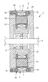
次に、図面を参照しながら、本発明の第1実施形態について説明するが、本発明はこれに限定されるものではない。図1は本発明の第1実施形態に係るアキシャルギャップ型電動機の内部構造を概略的に示す断面図、図2はそのステータを構成するポールメンバーの連結された状態を示す側面図、図3は図2の平面図である。第1実施例は、12スロット8極のアキシャルギャップ型電動機に適用した場合である。 Next, a first embodiment of the present invention will be described with reference to the drawings, but the present invention is not limited to this. FIG. 1 is a sectional view schematically showing the internal structure of an axial gap type electric motor according to a first embodiment of the present invention, FIG. 2 is a side view showing a state in which pole members constituting the stator are connected, and FIG. FIG. 3 is a plan view of FIG. 2. The first embodiment is applied to a 12-slot 8-pole axial gap type motor.
このアキシャルギャップ型電動機1は、ほぼ円盤状をなすステータ2と、ステータ2の両側に所定の空隙をもって対向的に配置される一対のロータ31,32とを含み、ロータ31,32は同一のロータ出力軸4を共有しており、ステータ2は、その内周側にロータ出力軸4を支持する軸受部6を備えている。
The axial gap type electric motor 1 includes a substantially disc-
なお実際には、ステータ2およびロータ31,32は、図示しないブラケット(筐体)内に収納され、ステータ2は、その外周側がブラケットに固定されている。したがって、ロータ31,32は、ロータ出力軸4,軸受部6およびステータ2を介してブラケットに支持されることになる。
In practice, the
ステータ2は、環状(いわゆるドーナツ状)に形成されたステータコア5と、ステータコア5の内周側に同軸的に挿入された軸受部6とを備え、それらが合成樹脂21によって一体的にモールドされている。この例において、軸受部6は、2つのラジアルボールベアリングを備えているが、他の軸受手段が採用されてもよい。
The
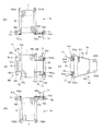
図2に示すように、ステータコア5は、複数個(この例では12個)のポールメンバー5a〜5lを環状につなぎ合わせることにより構成されている。各ポールメンバー5a〜5lはすべて同一形状であり、図4に、そのうちの一つのポールメンバー5aを抜粋して示す。なお、図4において、(a)をポールメンバー5aの正面図,(b)を平面図,(c)を右側面図,(d)を底面図としている。
As shown in FIG. 2, the
ポールメンバー5aは、図4(c)に示すように、複数枚の金属板を台形状に積層してなるティース(鉄心)51を備え、ティース51の周りには、その両側面を除いて合成樹脂からなるインシュレータ50が一体に形成されている。なお、ティース51は積層によるものの他に、粉体成形などによって一体的に成形することもできる。
As shown in FIG. 4 (c), the
インシュレータ50は、ティース51を図示しない成形金型のキャビティ内に入れ、そのキャビティ内に溶融樹脂を注入するインサート成形により形成することができる。この実施形態において、溶融樹脂は比較的流動性のよいSPS(シンジオタクチック−ポリスチレン)が用いられている。
The
この実施形態において、各ポールメンバー5a〜5lには、中央に固定子鉄心51が配置されているが、この固定子鉄心51を持たない構造、いわゆる空芯コイルを採用したポールメンバー5a〜5lに本発明の構造を適用してもよい。
In this embodiment, each of the
インシュレータ50は、ティース51の両側面に沿って左右一対として配置されるほぼ扇型のフランジ52,53を含む全体が断面H字形のボビン状に形成されている。この例において、フランジ52,53の扇状の開き角は30゜(360゜/12)である。このインシュレータ50があることにより、ティース51上にコイル7を整然と巻くことができ、また、ティース51とコイル7との間の電気的な絶縁が保たれる。
The
フランジ52,53には、隣接するポールメンバー同士を互いに連結するための連結手段が設けられている。この例では、一つのポールメンバーあたり、第1および第2の2つの連結手段を備えている。第1連結手段は、図4(c)において、フランジ52,53の幅の広い方の外周側に設けられ、第2連結手段は、幅の狭い方の内周側に設けられている。
The
第1連結手段は、フランジ52,53の一方の端縁501の外周側に形成されたボス541aと、他方の端縁502の外周側に形成された係合溝542aとを備え、また、第2連結手段は、フランジ52,53の一方の端縁501の内周側に形成されたボス541bと、他方の端縁502の内周側に形成された係合溝542bとを備えている。
The first connecting means includes a
第1連結手段のボス541aは、隣接するポールメンバー側の第1連結手段の係合溝542aと係合する関係にあり、第2連結手段のボス541bは、隣接するポールメンバー側の第2連結手段の係合溝542bと係合する関係にある。
The
なお、この例では、ボス541a,541bをともにフランジ52,53の一方の端縁501側に配置し、係合溝542a,542bをともにフランジ52,53の他方の端縁502側に配置しているが、ボスと係合溝の位置を入れ替えて、例えば第1連結手段側のボス541aを他方の端縁502側に配置し、係合溝542aを一方の端縁501側に配置してもよい。
In this example, both the
各連結手段は、適度な押圧力によって係合可能であり、かつ、係合された状態において相対的な回転を許容し得るように、ボス541a,541bは円柱状で、係合溝542a,542bはボスの直径よりも若干狭い開口部を有する、例えばC字状の溝であることが好ましい。
The
フランジ52,53には、コイル7の渡り線71を処理するための渡り線支持部材55,56がそれぞれ設けられている。渡り線支持部材55,56は、フランジ52,53の外周側の上端部から側方に向けて張り出すように形成されており、各ポールメンバー5a〜5lを環状に連結することに伴って、各渡り線支持部材55,56もステータコア2の側面に沿って環状に配置される(図2参照)。
The
この例において、当該電動機は3相であり、フランジ52側の渡り線支持部材55は、そのうちの1相分のコイル7の渡り線71を受け持ち、フランジ53側の渡り線支持部材56は、残りの2相分のコイル7の渡り線71を受け持つ。
In this example, the electric motor has three phases, and the connecting
そのため、フランジ52側の渡り線支持部材55には、1つの渡り線収納溝551が設けられており、フランジ53側の渡り線支持部材56には、2つの渡り線収納溝561,562が設けられている。
Therefore, the
なお、渡り線支持部材56のように、例えば2つの渡り線収納溝561,562が設けられる場合、その2本の渡り線71の絡まりや入れ違いを防止する意味で、渡り線支持部材56の上面側に一方の渡り線収納溝561を配置し、下面側に他方の渡り線収納溝562を配置することが好ましい。
Note that, for example, when two
また、渡り線収納溝551,561,562の各々は、一旦入れられた渡り線71が容易に抜け出ないようにするため、入り口が狭く内部が広い溝、例えば断面ほぼC字型の溝であることが好ましい。
In addition, each of the
渡り線支持部材55,56には、渡り線71の一部分を巻き付けておくための絡げ部58a〜58cが設けられている。この絡げ部は、渡り線収納溝ごとに設けられる。したがって、この例では、渡り線支持部材55側には、渡り線収納溝551に対応して1つの絡げ部58aが設けられ、渡り線支持部材56側には、渡り線収納溝561,562に対応して2つの絡げ部58b,58cが設けられている。
The connecting
各絡げ部58a〜58cはともに、渡り線支持部材55,56の両端からステータコア2の円周方向に沿って突設された一対のロッド581a,581bを備え、各ロッド581a,581bの先端部には、そのロッドに巻き付けられた渡り線71の脱落を防止するロッド径よりも大径のストッパ582がそれぞれ形成されている。
Each of the
なお、渡り線支持部材56のように、例えば2つの絡げ部58b,58cが設けられる場合、それに対する巻き付け作業を容易とするため、その一方の絡げ部58bと、他方の絡げ部58cは異なる高さ位置に配置されることが好ましい。
For example, when two
さらに、各フランジ52,53の外周側の上端に、ティース51に沿って巻回されたコイル7の両端を係止しておく一対のコイル係止溝59a,59bを設けることにより、巻回されたコイル7のほぐれなどを気にすることなく、その渡り線71を処理することができる。
Further, the
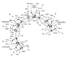
次に、図5〜7を参照して、ステータコア2の組立手順の一例を説明する。この例において、当該電動機は3相電動機であるから、図2に示す12個のポールメンバー5a〜5lのうち、例えばポールメンバー5a,5d,5g,5jがU相用,ポールメンバー5b,5e,5h,5kがV相用,ポールメンバー5c,5f,5i,5lがW相用であるとする。
Next, an example of the assembly procedure of the
また、一方の渡り線支持部材55の渡り線収納溝551および絡げ部58aをU相用として使用し、他方の渡り線支持部材56の渡り線収納溝561および絡げ部58bをV相用、同渡り線支持部材56の渡り線収納溝562および絡げ部58cをW相用として使用するものとする。
Further, the connecting
各相ごとに図示しない自動巻線機にてコイルを巻くのであるが、その巻線手順は同一であるため、ここではもっぱらU相について説明する。図5に示すように、U相用の4つのポールメンバー5a,5d,5g,5jに対して、例えばポールメンバー5a側からコイル7を巻いていく。
A coil is wound by an automatic winding machine (not shown) for each phase, but since the winding procedure is the same, only the U phase will be described here. As shown in FIG. 5, the
すなわち、所定長さの引出線Uaを確保して、まず、コイル7の一部分をポールメンバー5aに設けられている絡げ部58aの一方のロッド581aに所定回数巻き付けた後、一方のコイル係止溝59aに係止してインシュレータ50内に導き入れ、所定のターン数分巻回してコイル7を形成する。
That is, a lead wire Ua having a predetermined length is secured, and after first winding a part of the
しかる後、コイル7の終端側を他方のコイル係止溝59bに引っかけて他方のロッド581bに導いて所定回数巻き付ける。そして、おおよそ2つのポールメンバー分の長さに相当する渡り線71Uを確保して、次のポールメンバー5dに移り上記ポールメンバー5aと同様の手順でコイル7を形成する。
Thereafter, the terminal end side of the
残されたポールメンバー5g,ポールメンバー5jについても同様にしてコイル7を形成した後、最後のポールメンバー5jの絡げ部58aの他方のロッド581b側から引出線Ubを所定長さ分引き出して、U相分のコイル巻作業を終了する。
After forming the
上述した手順と同様にして、V相用のポールメンバー5b,5e,5h,5kおよびW相用のポールメンバー5c,5f,5i,5lについても、それぞれ渡り線71V,71Wでつなげながらコイル7を形成する。この場合、V相については、渡り線支持部材56にある外側の絡げ部58bを使用し、W相については、その内側にある絡げ部58cを使用する。なお、Va,VbはV相用の引出線,Wa,WbはW相用の引出線である。
In the same manner as described above, the
このようにして、3相分のポールメンバーユニットを形成した後、図6に示すように、渡り線71UでつなげられたU相用ポールメンバー5a,5d,5g,5jをそれらの外周側が内側で、内周側が外側となるようにほぼ円弧状に配置し、それら各ポールメンバー5a,5d,5g,5jの隣にV相用ポールメンバー5b,5e,5h,5kを配置し、それらの第1連結手段側のボス541aと係合溝542aとにより、ポールメンバー5aと5b,5dと5e,5gと5h,5jと5kとをそれぞれ連結する。
After forming pole member units for three phases in this way, as shown in FIG. 6, the
次に、図6で空いているポールメンバー間に、図7に示すように、W相用のポールメンバー5c,5f,5i,5lを配置して、これらの各ポールメンバー5c,5f,5i,5lを上記と同様に、第1連結手段側のボス541aと係合溝542aとにより、両隣の各ポールメンバーと連結する。
Next, as shown in FIG. 7,
このようにして、12個のポールメンバー5a〜5lを連結した後、それらの外周が外側となるように、両端に位置するポールメンバー5aと5lを図7の矢印方向に回して、ポールメンバー5aと5lとを、それらの第1連結手段側のボス541aと係合溝542aとにより連結する。また、各ポールメンバー5a〜5lの内周側同士を第2連結手段側のボス541bと係合溝542bとにより連結する。
After connecting the twelve
これにより、12個のポールメンバー5a〜5lが図2に示すように環状に組み立てられるのであるが、このとき、渡り線の処理を行う。すなわち、U相の渡り線71Uを例えばポールメンバー5aを起点として時計方向回りに、ポールメンバー5b,5c,5e,5f,5h,5i,5k,5lの各渡り線支持部材55の渡り線収納溝551内に入れる。
Thus, the twelve
同様に、V相の渡り線71Vを例えばポールメンバー5bを起点として時計方向回りに、ポールメンバー5c,5d,5f,5g,5i,5j,5l,5aの各渡り線支持部材56の渡り線収納溝561内に入れる。W相の渡り線71Wについても、例えばポールメンバー5cを起点として時計方向回りに、ポールメンバー5d,5e,5g,5h,5j,5k,5a,5bの各渡り線支持部材56の渡り線収納溝562内に入れる。
Similarly, the
最後に、ステータコア5の内周側に軸受部6を挿入した後、インサート成形により、図1に示すように、各ポールメンバーの外周部分および内周部分と、その内周部分に接する軸受部6の一部を合成樹脂21によって固める。
Finally, after the bearing portion 6 is inserted on the inner peripheral side of the
次に、図8〜図12を参照して、本発明の第2実施形態に係るアキシャルギャップ型電動機について説明する。なお、上述した第1実施形態と同一もしくは同一と見なされる箇所には同じ参照符号を付し、その説明は省略する。この第2実施例は、9スロット8極のアキシャルギャップ型電動機に適用した場合である。 Next, an axial gap type electric motor according to a second embodiment of the present invention will be described with reference to FIGS. In addition, the same referential mark is attached | subjected to the part considered the same as 1st Embodiment mentioned above, or the same, The description is abbreviate | omitted. The second embodiment is applied to a 9-slot 8-pole axial gap motor.
このアキシャルギャップ型電動機1aは、上記第1実施形態と同様にほぼ円盤状をなすステータ2と、ステータ2の両側に所定の空隙をもって対向的に配置される一対のロータ31,32とを含み、ロータ31,32は同一のロータ出力軸4を共有しており、ステータ2は、その内周側にロータ出力軸4を支持する軸受部6を備えている。なお、このアキシャルギャップ型電動機1aも図示しないブラケットに収納されている。
This axial gap type electric motor 1a includes a
ステータ2は、環状(ドーナツ状)に形成されたステータコア5と、ステータコア5の内周側に同軸的に挿入された軸受部6とを備え、それらが合成樹脂21によって一体的にモールドされている。
The
図9に示すように、ステータコア5は、複数個(この例では9スロット分)のポールメンバー5m〜5uを環状に繋ぎ合わせることにより構成されている。各ポールメンバー5m〜5uは全て同一形状であり、図11にその1つのポールメンバー5mを抜粋して示す。なお、図11において、ポールメンバー5mの正面図を(a)、平面図を(b)、底面図を(c)、左側面図(d)とし、図12は要部断面図である。
As shown in FIG. 9, the
ポールメンバー5mは、図11(a)に示すように、複数枚の電磁鋼板を半径方向に積層してなるティース(鉄心)51aを備え、ティース51aの周りには、その両側を除いて合成樹脂からなるインシュレータ50aが一体に形成されている。なお、ティース51は、粉末成形などによて一体的に形成してもよい。
As shown in FIG. 11 (a), the
インシュレータ50aは、ティース51aを図示しない成型金型内のキャビティに入れ、そのキャビティ内に溶融樹脂を注入するインサート成型により形成することができる。この実施形態においても、溶融樹脂は比較的流動性のよいSPS(シンジオタクチック−ポリスチレン)が用いられている。
The
この実施形態において、インシュレータ50aは、ティース51aにインサート成型によって形成されているが、例えば、インシュレータ50aを予め2つのピースから構成しておき、ティース51aを挟んでそれらを両側から挟んで取り付けるようにしてもよい。
In this embodiment, the
ティース51aには、ロータ31,32の回転方向、この実施形態では時計回り方向に沿って所定角度傾斜されたスキュー511aが形成されている。この実施形態において、スキュー角は、5°に設定されており、これによれば、コギングトルクの発生を抑えることができ、エネルギー変換効率がよくなる。
The
スキュー511aは、隣接するポールメンバー間のギャップ面に対して直線形状に形成されているが、これ以外に円弧形状であってもよく、コギングトルクを効果的に抑える効果が得られればその形状は特に限定されない。
The
インシュレータ50aは、ティース51aの両側面に沿って左右一対として配置されるほぼ扇形のフランジ52a,53aを含む全体が断面H字型のボビン状に形成されている。このインシュレータ50aの存在により、ティース50aに対してコイル7を整然と巻くことができる。
The
フランジ52a,53aには、隣接するポールメンバー同士を連結するための連結手段が設けられている。この例において、連結手段は、フランジ52a、52bの内周側に設けられている。
The
連結手段は、フランジ52a、53aの一方の端縁501の内周側に形成されたボス541cと、他方の端縁502の内周側に形成された係合溝542cとからなり、それらが互いに係合し合うことにより、図9に示すような、環状のステータコア5が形成される。
The connecting means includes a
この実施形態において、ボス541cおよび係合溝542cは、角柱体およびそれに合致する矩形溝からなり、それらを互いに係合させることにより、スキュー511aの位置決め手段としても併用されている。
In this embodiment, the
フランジ52a、53aの側面には、コイル7の渡り線71を処理するための渡り線収納溝55a〜55cが3箇所設けられている。この実施形態において、各渡り線収納溝55a〜55cは、それぞれフランジ52a、53aの側面に外周側に沿って円弧状に形成されており、一方のフランジ52a側には2本の渡り線収納溝55a、55bが形成されており、残りの渡り線55cは他方のフランジ53a側に形成されている。
On the side surfaces of the
図12に示すように、各渡り線収納溝55a〜55cはU字状の溝からなるが、より好ましくは、開口部の溝幅が内部の溝幅と同一もしくはそれ以下に設計されていることが好ましい。これによれば、渡り線71の抜け止め効果が得られる。
As shown in FIG. 12, each of the
各渡り線収納溝55a〜55cは、また、その先端部分(開放端側)が他の部分に比べて薄肉化されていることが好ましい。これによれば、各ポールメンバー5m〜5uを連結した後、合成樹脂21によって一体化する際に溶融樹脂の熱が先端部分に伝播することにより、先端部分が軟化して内部に収納された渡り線71を包み込むことで、渡り線71の抜け止め効果がより一層向上する。
Each of the connecting
また、渡り線収納溝55a〜55cが2箇所以上併設されている場合、すなわち、図12に示す、渡り線収納溝55a、55bのように設置された場合において、渡り線収納溝55a、55b同士は、段差部を介して高さ位置が異なるように設置されている。なお、この実施形態においての高さ位置とは、軸方向の高さをいう。
When two or more
この実施形態においては、外周側の渡り線収納溝55aが内周側の渡り線収納溝55bよりも一段低く形成されている。これによれば、溶融樹脂が金型キャビティ内をスムーズに流れるため、ステータコア2と合成樹脂21との間に隙間(ボイド)などを形成することなく、まんべんなく流し込むことができる。
In this embodiment, the outer connecting
各渡り線収納溝55a〜55cの内、内径側の渡り線収納溝(この実施形態では、渡り線収納溝55b、55c)の内周側の各外壁面57aが半径方向に向かって傾斜されたテーパー面からなることが好ましい。これによれば、中心から外周側に向かって流れ込んでくる溶融樹脂をより一層スムーズに外周側に流れ込ませることができる。
Outer wall surfaces 57a on the inner peripheral side of the inner diameter side of the connecting
さらに、溶融樹脂を流れやすくする手段として、フランジ52a、53aの一部には、ポールメンバー5m〜5u同士を繋ぎ合わせて一体化する際に、樹脂の流れをよくするための樹脂導入路521a、531aが設けられている。樹脂導入路521a、531aは、半径方向に沿ってフランジ52a、53aの内径側に形成されたコ字状に溝からなり、ここから溶融樹脂がフランジ52a、53aの側面を通って外周部に流れ込む。
Further, as means for facilitating the flow of the molten resin, a part of the
この実施形態において、樹脂導入路58aは、フランジ52a、53aの内周側に半径方向に沿って1箇所のみ設けられているが、例えば複数箇所に設けてもよく、その数および形状は特に限定されない。
In this embodiment, the
各渡り線収納溝55a〜55cには、半径方向に沿って切り欠かれた係止溝56a〜56dが設けられている。係止溝56a〜56dは、各渡り線収納溝55a〜55cに2箇所設けられており、それらに渡り線71の一部を引っ掛けておくことにより、運搬時などに渡り線71が解れるのを防止する。
Each of the
各ステータコア5m〜5uの組立・結線手順は、上述した第1実施形態と基本的に同じであるが、9スロット型の場合は、U・V・W相をそれぞれ(+)→(−)→(+)の順に配置する必要があり、真ん中のステータコアの巻回方向を逆にするか、結線を逆に接続する必要がある。
The procedure for assembling and connecting the
ステータコア5m〜5uの組立後は、合成樹脂21によってインサート成型することでステータ2として形成される。通常、樹脂は溶融状態でステータ2の中心からキャビティ内に流し込まれ、外周側に向かって送り込まれるが、この第2実施形態では、渡り線収納溝55a〜55cがフランジ52a,53aの側面に形成されていたり、テーパー面を設けるなど、溶融樹脂の流れをスムーズにするための工夫がなされているため、より均質なステータ2が得られる。
After the assembly of the
このように、最終的に各ポールメンバーを合成樹脂21によって永久的に固める場合、各ポールメンバーの内周側に設けられている第2連結手段は必ずしも必要とされない。また、上記の例では、一対のロータ31,32を備えているが、片面ロータであってもよい。このように、本発明には、その要旨を逸脱しない範囲内および技術的均等とされる範囲内で、種々の変形例が含まれる。
Thus, when each pole member is finally permanently fixed with the
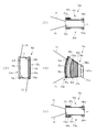
なお、図13(a)および(b)に示すように、各ポールメンバー5a〜5l(第1実施形態)、5m〜5uに内蔵される固定子鉄心51は、そのフランジ511(512),512a(513a)の積層方向に垂直な面への投影面積がスキューの有無に関わらず、左右同じであることが好ましい。
As shown in FIGS. 13A and 13B, the
すなわち、図13(a)に示すように、スキューなしの場合は、中央の巻回部513を挟んで左右に形成されたフランジ511,522の投影面積が左右対称となっている。
That is, as shown in FIG. 13A, when there is no skew, the projected areas of the
また、図13(b)に示すように、ティース51aのギャップ間にスキュー511aが形成されている場合においても、巻回部514aの一部がフランジ513a側に張り出すように形成されていることにより、左右のフランジ部512a、513aの積層方向に垂直な面への各投影面積が同じになるように形成されている。
Further, as shown in FIG. 13B, even when the
これによれば、面積が同じになることにより、巻線をポールメンバーからはみ出すことなく一様に納めることができる。また、巻線がはみ出ないため、ポールメンバー同士を干渉するさせることなく配置できる。 According to this, since the areas are the same, the winding can be uniformly accommodated without protruding from the pole member. Further, since the winding does not protrude, the pole members can be arranged without interfering with each other.
なお、固定子鉄心51を持たない場合には、各インシュレータ5a〜5uに形成されたフランジ部52a,53aの投影面積を同じにすることにより、同様の効果が得られる。
In addition, when not having the
このアキシャルギャップ型電動機によれば、渡り線71の処理が容易になることにより、組立性がよく、生産性の向上が図れる。また、コイルの仕様や巻き方についての設計自由度がよく、高効率なモータを得ることができる。さらには、各パーツを一体的に組み込むことで、より安価に生産することができる。
According to the axial gap type electric motor, the
1,1a アキシャルギャップ型電動機
2 ステータ
31,32 ロータ
4 出力軸
5 ステータコア
5a〜5l,5m〜5u ポールメンバー
50 インシュレータ
51,51a ティース
52,53(52a,53a) フランジ
541a,541b ボス
542a,542b 係合溝
55,56 渡り線支持部材
551,561,562 渡り線収納溝
58a〜58c 絡げ部
59a,59b コイル係止溝
6 軸受部
7 コイル
71U,71V,71W 渡り線
1, 1a Axial
Claims (15)
上記ステータは、環状に連結される複数個のポールメンバーを備え、上記各ポールメンバーは、固定子鉄心を有するとともに、上記固定子鉄心にはコイル巻回用の左右一対のフランジを含むボビン形状のインシュレータが一体的に形成されており、上記インシュレータに、隣接する上記各ポールメンバー同士を連結するための連結手段が設けられていることを特徴とするアキシャルギャップ型電動機。 In an axial gap type electric motor including a stator and a rotor, each of which is formed in a substantially disc shape and is disposed opposite to the same rotation shaft with a predetermined gap,
The stator includes a plurality of pole members connected in an annular shape, and each of the pole members has a stator core, and the stator core has a bobbin shape including a pair of left and right flanges for winding a coil. An axial gap type electric motor, wherein an insulator is integrally formed, and a connecting means for connecting adjacent pole members to each other is provided on the insulator .
Priority Applications (6)
| Application Number | Priority Date | Filing Date | Title |
|---|---|---|---|
| JP2003416651A JP4305649B2 (en) | 2003-02-26 | 2003-12-15 | Axial gap type electric motor |
| TW093103659A TWI327403B (en) | 2003-02-26 | 2004-02-16 | Axial gap electronic motor |
| US10/782,756 US7221073B2 (en) | 2003-02-26 | 2004-02-23 | Axial gap electronic motor |
| KR1020040012522A KR101022389B1 (en) | 2003-02-26 | 2004-02-25 | Axial gap electronic motor |
| CNB200410006785XA CN100544168C (en) | 2003-02-26 | 2004-02-26 | Axial air gap type electric motor |
| CN2008101490657A CN101447701B (en) | 2003-02-26 | 2004-02-26 | Axial gap version dynamo-electric motor |
Applications Claiming Priority (2)
| Application Number | Priority Date | Filing Date | Title |
|---|---|---|---|
| JP2003049012 | 2003-02-26 | ||
| JP2003416651A JP4305649B2 (en) | 2003-02-26 | 2003-12-15 | Axial gap type electric motor |
Related Child Applications (1)
| Application Number | Title | Priority Date | Filing Date |
|---|---|---|---|
| JP2006276449A Division JP4501919B2 (en) | 2003-02-26 | 2006-10-10 | Axial gap type electric motor |
Publications (3)
| Publication Number | Publication Date |
|---|---|
| JP2004282989A JP2004282989A (en) | 2004-10-07 |
| JP2004282989A5 JP2004282989A5 (en) | 2005-09-29 |
| JP4305649B2 true JP4305649B2 (en) | 2009-07-29 |
Family
ID=32871226
Family Applications (1)
| Application Number | Title | Priority Date | Filing Date |
|---|---|---|---|
| JP2003416651A Expired - Lifetime JP4305649B2 (en) | 2003-02-26 | 2003-12-15 | Axial gap type electric motor |
Country Status (5)
| Country | Link |
|---|---|
| US (1) | US7221073B2 (en) |
| JP (1) | JP4305649B2 (en) |
| KR (1) | KR101022389B1 (en) |
| CN (2) | CN101447701B (en) |
| TW (1) | TWI327403B (en) |
Families Citing this family (91)
| Publication number | Priority date | Publication date | Assignee | Title |
|---|---|---|---|---|
| JP2005171835A (en) * | 2003-12-10 | 2005-06-30 | Fujitsu General Ltd | Blower |
| JP2006067701A (en) * | 2004-08-26 | 2006-03-09 | Aisin Seiki Co Ltd | Stator for dynamo-electric machine |
| JP4687871B2 (en) * | 2004-11-26 | 2011-05-25 | 株式会社富士通ゼネラル | Axial gap type electric motor |
| JP2006191782A (en) * | 2004-12-09 | 2006-07-20 | Yamaha Motor Co Ltd | Rotating-electric machine |
| JP2006180618A (en) * | 2004-12-22 | 2006-07-06 | Fujitsu General Ltd | Axial gap type motor |
| JP2006197706A (en) * | 2005-01-13 | 2006-07-27 | Fujitsu General Ltd | Axial gap type motor |
| JP5299649B2 (en) * | 2005-01-24 | 2013-09-25 | 株式会社富士通ゼネラル | Manufacturing method of axial air gap type motor |
| JP4725721B2 (en) * | 2005-01-24 | 2011-07-13 | 株式会社富士通ゼネラル | Axial air gap type electric motor |
| JP2006288012A (en) * | 2005-03-31 | 2006-10-19 | Fujitsu General Ltd | Axial gap type motor |
| JP4720980B2 (en) * | 2005-04-13 | 2011-07-13 | 株式会社富士通ゼネラル | Axial air gap type electric motor |
| JP4720278B2 (en) * | 2005-04-27 | 2011-07-13 | 株式会社富士通ゼネラル | Axial air gap type electric motor |
| JP4706339B2 (en) | 2005-06-03 | 2011-06-22 | 株式会社富士通ゼネラル | Axial air gap type electric motor |
| JP4857615B2 (en) | 2005-06-09 | 2012-01-18 | 日産自動車株式会社 | Coil connection structure of rotating electrical machine |
| JP4816879B2 (en) * | 2005-06-30 | 2011-11-16 | 株式会社富士通ゼネラル | Axial air gap type electric motor |
| JP4956774B2 (en) * | 2005-08-24 | 2012-06-20 | 日産自動車株式会社 | Wiring structure of axial gap type motor |
| JP4834433B2 (en) * | 2006-03-15 | 2011-12-14 | 株式会社富士通ゼネラル | Manufacturing method of stator core for axial air gap type motor |
| EP2012408A4 (en) * | 2006-03-27 | 2018-02-21 | Daikin Industries, Ltd. | Armature core, motor using it, and its manufacturing method |
| KR100663641B1 (en) * | 2006-04-06 | 2007-01-05 | 주식회사 아모텍 | Method for making integrated stator, brushless direct current motor of radial core type having a structure of double rotors and method for making the same using the method |
| US7719147B2 (en) * | 2006-07-26 | 2010-05-18 | Millennial Research Corporation | Electric motor |
| US8450898B2 (en) * | 2006-09-01 | 2013-05-28 | Resmed Motor Technologies Inc | Insulator for stator assembly of brushless DC motor |
| JP4868147B2 (en) | 2006-11-08 | 2012-02-01 | 株式会社富士通ゼネラル | Axial air gap type electric motor |
| JP2008131682A (en) * | 2006-11-16 | 2008-06-05 | Fujitsu General Ltd | Axial air gap type motor |
| JP2008131683A (en) * | 2006-11-16 | 2008-06-05 | Fujitsu General Ltd | Axial air gap type motor |
| JP4940955B2 (en) * | 2007-01-09 | 2012-05-30 | ダイキン工業株式会社 | Axial gap type motor and compressor |
| JP5320676B2 (en) * | 2007-01-26 | 2013-10-23 | ダイキン工業株式会社 | Coil manufacturing method, armature manufacturing method |
| JP5052288B2 (en) * | 2007-06-28 | 2012-10-17 | 信越化学工業株式会社 | Axial gap type rotating machine |
| JP5333996B2 (en) | 2007-08-17 | 2013-11-06 | 株式会社安川電機 | Stator and rotating electric machine using the same |
| JP2008245504A (en) * | 2007-10-24 | 2008-10-09 | Daikin Ind Ltd | Manufacturing method of armature core, and armature core |
| FR2926935B1 (en) * | 2008-01-30 | 2012-06-08 | Tecddis | AXIAL FLUX AND PERMANENT MAGNET ELECTRIC MACHINE |
| MX2011003295A (en) * | 2008-09-29 | 2011-07-29 | In Motion Technologies Pty Ltd | Winding insulation arrangement for axial flux machines. |
| KR101026083B1 (en) * | 2008-12-23 | 2011-03-31 | 주식회사 아모텍 | Slim type stator and method of making the same |
| JP5509607B2 (en) * | 2009-02-05 | 2014-06-04 | 株式会社富士通ゼネラル | Axial air gap type electric motor |
| GB0902394D0 (en) | 2009-02-13 | 2009-04-01 | Isis Innovation | Electric machine- cooling |
| GB0902390D0 (en) * | 2009-02-13 | 2009-04-01 | Isis Innovation | Electric machine - flux |
| GB0902393D0 (en) | 2009-02-13 | 2009-04-01 | Isis Innovation | Elaectric machine - modular |
| GB0906284D0 (en) | 2009-04-14 | 2009-05-20 | Isis Innovation | Electric machine-evaporative cooling |
| KR101134969B1 (en) | 2009-11-19 | 2012-04-09 | 현대자동차주식회사 | Method for manufacturing stator for electric water pump |
| KR101072328B1 (en) * | 2009-11-19 | 2011-10-11 | 현대자동차주식회사 | Electric water pump |
| KR101134968B1 (en) | 2009-11-19 | 2012-04-09 | 현대자동차주식회사 | Electric water pump |
| KR101072327B1 (en) | 2009-11-19 | 2011-10-11 | 현대자동차주식회사 | Electric water pump |
| KR101134970B1 (en) | 2009-11-19 | 2012-04-09 | 현대자동차주식회사 | Electric water pump |
| KR101074939B1 (en) * | 2009-11-23 | 2011-10-18 | 뉴모텍(주) | Magmate Winding Frame and Stator Core with the Same |
| JP4716060B2 (en) * | 2009-11-30 | 2011-07-06 | 株式会社富士通ゼネラル | Axial gap type electric motor and pump device |
| DE102009056676A1 (en) * | 2009-12-02 | 2011-06-09 | Volkswagen Ag | Winding for an electric machine and a method for producing such a winding |
| DE102009056855A1 (en) * | 2009-12-03 | 2011-06-09 | Wilo Se | Production of a chain-wound stator for electric motors |
| US8339011B2 (en) * | 2009-12-07 | 2012-12-25 | Hamilton Sundstrand Corporation | Rotor assembly wire support |
| KR101150990B1 (en) * | 2010-06-19 | 2012-06-13 | 김유정 | Brushless dc motor with slotless stator core |
| KR101130978B1 (en) * | 2010-06-23 | 2012-03-28 | 주식회사 아모텍 | Slim type stator and method of making the same, slim type motor having the stator, and direct drive apparatus for drum-washing machine |
| JP2010233449A (en) * | 2010-07-20 | 2010-10-14 | Sumida Electric Co Ltd | Continuously wound coil, set of continuously wound coil, and stator |
| GB201013881D0 (en) * | 2010-08-19 | 2010-10-06 | Oxford Yasa Motors Ltd | Electric machine - construction |
| KR101026084B1 (en) * | 2010-10-21 | 2011-03-31 | 주식회사 아모텍 | Slim type motor having slim type stator, and direct drive apparatus for drum-washing machine using the same |
| KR101317892B1 (en) * | 2011-01-24 | 2013-10-16 | 주식회사 아모텍 | Amorphous Stator and Producing Method thereof |
| KR101217223B1 (en) * | 2011-03-25 | 2012-12-31 | 주식회사 아모텍 | Stator Having Division Type Amorphous Cores and Axial Gap Type Electric Motor Using the Same |
| CN102130549A (en) * | 2011-04-13 | 2011-07-20 | 河南豫通电机股份公司 | Motor |
| JP2013090461A (en) * | 2011-10-19 | 2013-05-13 | Denso Corp | Stator of axial gap type rotary electric machine, and axial gap type rotary electric machine |
| CN103138421B (en) * | 2011-11-30 | 2016-03-09 | 台达电子工业股份有限公司 | radial air gap motor and stator structure |
| JP2013118750A (en) * | 2011-12-02 | 2013-06-13 | Hitachi Ltd | Axial gap type rotary electric machine and manufacturing method thereof |
| JP5859297B2 (en) * | 2011-12-07 | 2016-02-10 | 株式会社日立製作所 | Rotating electric machine |
| US9106119B2 (en) * | 2011-12-20 | 2015-08-11 | GM Global Technology Operations LLC | Support ring for electric machine rotors |
| JP5879121B2 (en) * | 2011-12-27 | 2016-03-08 | 株式会社日立産機システム | Axial gap rotating electric machine |
| US20130181556A1 (en) * | 2012-01-17 | 2013-07-18 | Regal Beloit America, Inc. | Electric motor |
| US20140015349A1 (en) * | 2012-07-11 | 2014-01-16 | Remy Technologies, Llc | Interlocking coil isolators for resin retention in a segmented stator assembly |
| JP5532274B2 (en) * | 2012-11-29 | 2014-06-25 | シナノケンシ株式会社 | Electric motor stator and electric motor |
| JP6003587B2 (en) * | 2012-11-30 | 2016-10-05 | 株式会社富士通ゼネラル | Electric motor |
| WO2014115255A1 (en) * | 2013-01-23 | 2014-07-31 | 株式会社 日立製作所 | Axial gap type rotating electric machine |
| CN104218698B (en) * | 2013-06-03 | 2017-11-03 | 三菱电机株式会社 | The manufacture method of the stator of electric rotating machine, electric rotating machine and electric rotating machine |
| CN105379072B (en) * | 2013-07-26 | 2019-04-09 | 株式会社日立产机系统 | The manufacturing method of axial gap electric motor and its winding |
| WO2015145901A1 (en) * | 2014-03-28 | 2015-10-01 | 株式会社日立産機システム | Axial-air-gap motor and bobbin for motor |
| EP3131188B1 (en) * | 2014-04-11 | 2022-02-23 | Hitachi Industrial Equipment Systems Co., Ltd. | Axial air gap rotating electric machine |
| CN106464111B (en) * | 2014-04-14 | 2019-09-27 | 株式会社日立产机系统 | Axail air gap type rotating electric machine |
| US11165312B2 (en) * | 2014-04-14 | 2021-11-02 | Hitachi Industrial Equipment Systems Co., Ltd. | Axial-gap dynamo-electric machine |
| US10536042B2 (en) | 2014-04-14 | 2020-01-14 | Hitachi Industrial Equipment Systems Co., Ltd. | Axial air gap type electric motor |
| GB2531745A (en) * | 2014-10-28 | 2016-05-04 | Moeller Motors Kg | Electrical machines with SMC cores |
| CA3032539C (en) * | 2015-11-20 | 2022-07-19 | Kelso Energy Ltd. | Recessed-magnet flywheel construction for vertical axis wind turbines |
| GB2563515B (en) * | 2016-04-08 | 2021-12-15 | Mitsubishi Electric Corp | Stator, motor, blower, vacuum cleaner, and method for attaching hall-effect sensor |
| US10992203B2 (en) | 2016-05-18 | 2021-04-27 | Hitachi Industrial Equipment Systems Co., Ltd. | Axial gap type rotary electric machine |
| CN110062742B (en) * | 2016-12-28 | 2021-04-13 | 莱特拉姆有限责任公司 | Axial flux motor for conveyor |
| US10819178B2 (en) | 2017-01-17 | 2020-10-27 | Regal Beloit America, Inc. | Stator assembly including insulation member and method of assembly thereof |
| EP3579386A4 (en) * | 2017-01-31 | 2020-10-21 | Hitachi Industrial Equipment Systems Co., Ltd. | Axial gap rotary electric machine |
| CN109478809B (en) * | 2017-01-31 | 2020-09-18 | 株式会社日立产机系统 | Axial gap type rotating electric machine |
| DE102017204401A1 (en) * | 2017-03-16 | 2018-09-20 | Brose Fahrzeugteile GmbH & Co. Kommanditgesellschaft, Würzburg | Segmented stator for one or in an axial flow machine |
| CN108736602B (en) * | 2017-04-14 | 2021-05-14 | 台达电子工业股份有限公司 | Axial flux electric machine |
| CN107800245B (en) * | 2017-10-18 | 2019-12-31 | 江苏大学 | Water-cooling soft magnetic composite material disc type motor |
| US11456629B2 (en) * | 2017-12-07 | 2022-09-27 | Kyocera Industrial Tools Corporation | Stator with divided cores connected circumferentially |
| FR3075505B1 (en) * | 2017-12-18 | 2022-03-11 | Whylot Sas | MOTOR STATOR OR ELECTROMAGNETIC GENERATOR WITH INDIVIDUAL WINDING SUPPORT SNAP-ON ON AN ASSOCIATED TOOTH |
| ES2835602T3 (en) | 2018-01-12 | 2021-06-22 | Carrier Corp | Electromagnetic machine |
| EP3745559B1 (en) * | 2019-05-27 | 2022-03-09 | Magnax Bv | Stator for an axial flux machine |
| DE102021106186A1 (en) * | 2021-03-15 | 2022-09-15 | Ebm-Papst Mulfingen Gmbh & Co. Kg | Modular, segmented stator package |
| CN113131706B (en) * | 2021-04-27 | 2022-04-29 | 山东大学 | Disc type permanent magnet synchronous motor, energy storage flywheel and method |
| CN114243979A (en) * | 2021-12-13 | 2022-03-25 | 深圳市金岷江智能装备有限公司 | Stator winding and transition line method |
| CN114530952B (en) * | 2022-04-22 | 2022-07-19 | 中山大洋电机股份有限公司 | Bar-shaped stator and wiring method thereof |
Family Cites Families (18)
| Publication number | Priority date | Publication date | Assignee | Title |
|---|---|---|---|---|
| US4095150A (en) * | 1976-07-12 | 1978-06-13 | Karlheinz Senckel | Two-phase asynchronous motor |
| US4761590A (en) * | 1987-07-20 | 1988-08-02 | Polestar Magnetronics Inc. | Electric motor |
| US4959578A (en) * | 1987-11-24 | 1990-09-25 | Axial Electric, Inc. | Dual rotor axial air gap induction motor |
| JP3680482B2 (en) * | 1997-03-28 | 2005-08-10 | 松下電器産業株式会社 | Electric motor stator constituent member, electric motor stator, electric motor manufacturing method |
| JP3279279B2 (en) * | 1998-06-30 | 2002-04-30 | 三菱電機株式会社 | Iron core equipment |
| JP3421251B2 (en) * | 1998-08-21 | 2003-06-30 | ミネベア株式会社 | Rotating electric machine and its bobbin |
| JP4234831B2 (en) * | 1998-12-28 | 2009-03-04 | 日本電産シバウラ株式会社 | Axial gap motor |
| JP4468589B2 (en) * | 1999-02-12 | 2010-05-26 | シラー,ヘルムート | Electric machine |
| US6445105B1 (en) * | 1999-04-06 | 2002-09-03 | General Electric Company | Axial flux machine and method of fabrication |
| KR20000065845A (en) * | 1999-04-09 | 2000-11-15 | 장병우 | Coil bobbin applied to stator core for motor |
| US6373162B1 (en) * | 1999-11-11 | 2002-04-16 | Ford Global Technologies, Inc. | Permanent magnet electric machine with flux control |
| TW508891B (en) * | 2000-02-21 | 2002-11-01 | Misubishi Electric Corp | Stator iron core of electric motor, manufacturing method thereof, electric motor, and compresor |
| JP3269497B2 (en) * | 2000-03-06 | 2002-03-25 | 松下電器産業株式会社 | Motor stator |
| CN2443526Y (en) * | 2000-09-30 | 2001-08-15 | 许俊甫 | Structure of stator winding slot base with loop stabilizer |
| JP3749444B2 (en) * | 2001-03-15 | 2006-03-01 | 三菱電機株式会社 | core |
| US6573632B2 (en) * | 2001-07-06 | 2003-06-03 | Chun-Pu Hsu | Structure of a stator forming an annularly closed stable structure |
| KR200284488Y1 (en) | 2002-05-09 | 2002-08-03 | 김준 | Stator for BLDC Motor Using Segmental Stator Cores and BLDC Motor Using the Same |
| JP4003058B2 (en) * | 2002-07-17 | 2007-11-07 | 株式会社富士通ゼネラル | Induction motor |
-
2003
- 2003-12-15 JP JP2003416651A patent/JP4305649B2/en not_active Expired - Lifetime
-
2004
- 2004-02-16 TW TW093103659A patent/TWI327403B/en active
- 2004-02-23 US US10/782,756 patent/US7221073B2/en not_active Expired - Lifetime
- 2004-02-25 KR KR1020040012522A patent/KR101022389B1/en not_active IP Right Cessation
- 2004-02-26 CN CN2008101490657A patent/CN101447701B/en not_active Expired - Lifetime
- 2004-02-26 CN CNB200410006785XA patent/CN100544168C/en not_active Expired - Lifetime
Also Published As
| Publication number | Publication date |
|---|---|
| KR101022389B1 (en) | 2011-03-22 |
| US7221073B2 (en) | 2007-05-22 |
| TW200507413A (en) | 2005-02-16 |
| KR20040076792A (en) | 2004-09-03 |
| TWI327403B (en) | 2010-07-11 |
| CN100544168C (en) | 2009-09-23 |
| CN101447701A (en) | 2009-06-03 |
| US20040164641A1 (en) | 2004-08-26 |
| JP2004282989A (en) | 2004-10-07 |
| CN1543042A (en) | 2004-11-03 |
| CN101447701B (en) | 2011-09-14 |
Similar Documents
| Publication | Publication Date | Title |
|---|---|---|
| JP4305649B2 (en) | Axial gap type electric motor | |
| JP4501919B2 (en) | Axial gap type electric motor | |
| CN1874114B (en) | Production method for rotating electric machine and stator coils, and electric power steering motor | |
| JP4655764B2 (en) | Rotating electric machine | |
| US7626303B2 (en) | Stator for inner rotor type mold brushless motor | |
| US9806576B2 (en) | Armature, armature manufacturing method, and rotating electrical device | |
| US9698639B2 (en) | Rotating electrical machine and method for manufacturing rotating electrical machine | |
| JP4680154B2 (en) | Rotating electric machine and manufacturing method thereof | |
| JP5974592B2 (en) | Armature and motor | |
| JP2011234537A (en) | Bobbin for rotating electric machine, manufacturing method of rotating electric machine and bobbin for the same | |
| JP3572209B2 (en) | Coil winding method | |
| JP2006187073A (en) | Insulator, stator, and motor | |
| WO2018138859A1 (en) | Axial gap-type rotary electric machine | |
| JP7297102B2 (en) | Stator for rotating electrical machine, rotating electrical machine, method for manufacturing stator for rotating electrical machine, and method for manufacturing rotating electrical machine | |
| JP2002247789A (en) | Construction and manufacturing method of stator coil for rotating field electric apparatus | |
| TW201828572A (en) | Axial gap type rotating electric machine | |
| JP2023129460A (en) | stator structure | |
| JP5862869B2 (en) | Molded motor | |
| JP2014225968A (en) | Stator of rotary electric machine | |
| JP6241332B2 (en) | Stator winding, stator winding manufacturing method, stator, rotating electric machine and wheel | |
| JP4842647B2 (en) | Electric motor | |
| JP6468124B2 (en) | Manufacturing method of rotating electrical machine and manufacturing apparatus of stator used in the rotating electrical machine | |
| JP5916650B2 (en) | Rotating electric machine armature, rotating electric machine, method of manufacturing rotating electric machine coil, method of manufacturing rotating electric machine armature | |
| JP2022070591A (en) | Rotary electric machine insulator and rotary electric machine | |
| JPS6036704B2 (en) | Manufacturing method of flat motor rotor coil |
Legal Events
| Date | Code | Title | Description |
|---|---|---|---|
| A521 | Request for written amendment filed |
Free format text: JAPANESE INTERMEDIATE CODE: A523 Effective date: 20050712 |
|
| A621 | Written request for application examination |
Free format text: JAPANESE INTERMEDIATE CODE: A621 Effective date: 20060728 |
|
| A977 | Report on retrieval |
Free format text: JAPANESE INTERMEDIATE CODE: A971007 Effective date: 20081224 |
|
| A131 | Notification of reasons for refusal |
Free format text: JAPANESE INTERMEDIATE CODE: A131 Effective date: 20090107 |
|
| A521 | Request for written amendment filed |
Free format text: JAPANESE INTERMEDIATE CODE: A523 Effective date: 20090309 |
|
| TRDD | Decision of grant or rejection written | ||
| A01 | Written decision to grant a patent or to grant a registration (utility model) |
Free format text: JAPANESE INTERMEDIATE CODE: A01 Effective date: 20090408 |
|
| A01 | Written decision to grant a patent or to grant a registration (utility model) |
Free format text: JAPANESE INTERMEDIATE CODE: A01 |
|
| A61 | First payment of annual fees (during grant procedure) |
Free format text: JAPANESE INTERMEDIATE CODE: A61 Effective date: 20090421 |
|
| R151 | Written notification of patent or utility model registration |
Ref document number: 4305649 Country of ref document: JP Free format text: JAPANESE INTERMEDIATE CODE: R151 |
|
| FPAY | Renewal fee payment (event date is renewal date of database) |
Free format text: PAYMENT UNTIL: 20120515 Year of fee payment: 3 |
|
| FPAY | Renewal fee payment (event date is renewal date of database) |
Free format text: PAYMENT UNTIL: 20130515 Year of fee payment: 4 |
|
| S531 | Written request for registration of change of domicile |
Free format text: JAPANESE INTERMEDIATE CODE: R313532 |
|
| R350 | Written notification of registration of transfer |
Free format text: JAPANESE INTERMEDIATE CODE: R350 |
|
| EXPY | Cancellation because of completion of term |