JP4304075B2 - 内燃機関用始動装置 - Google Patents
内燃機関用始動装置 Download PDFInfo
- Publication number
- JP4304075B2 JP4304075B2 JP2003558332A JP2003558332A JP4304075B2 JP 4304075 B2 JP4304075 B2 JP 4304075B2 JP 2003558332 A JP2003558332 A JP 2003558332A JP 2003558332 A JP2003558332 A JP 2003558332A JP 4304075 B2 JP4304075 B2 JP 4304075B2
- Authority
- JP
- Japan
- Prior art keywords
- fuel
- pressure
- accumulator
- hole
- coil
- Prior art date
- Legal status (The legal status is an assumption and is not a legal conclusion. Google has not performed a legal analysis and makes no representation as to the accuracy of the status listed.)
- Expired - Fee Related
Links
Images


Classifications
-
- F—MECHANICAL ENGINEERING; LIGHTING; HEATING; WEAPONS; BLASTING
- F02—COMBUSTION ENGINES; HOT-GAS OR COMBUSTION-PRODUCT ENGINE PLANTS
- F02N—STARTING OF COMBUSTION ENGINES; STARTING AIDS FOR SUCH ENGINES, NOT OTHERWISE PROVIDED FOR
- F02N99/00—Subject matter not provided for in other groups of this subclass
- F02N99/002—Starting combustion engines by ignition means
- F02N99/006—Providing a combustible mixture inside the cylinder
-
- F—MECHANICAL ENGINEERING; LIGHTING; HEATING; WEAPONS; BLASTING
- F02—COMBUSTION ENGINES; HOT-GAS OR COMBUSTION-PRODUCT ENGINE PLANTS
- F02D—CONTROLLING COMBUSTION ENGINES
- F02D41/00—Electrical control of supply of combustible mixture or its constituents
- F02D41/02—Circuit arrangements for generating control signals
- F02D41/04—Introducing corrections for particular operating conditions
- F02D41/06—Introducing corrections for particular operating conditions for engine starting or warming up
- F02D41/062—Introducing corrections for particular operating conditions for engine starting or warming up for starting
-
- F—MECHANICAL ENGINEERING; LIGHTING; HEATING; WEAPONS; BLASTING
- F02—COMBUSTION ENGINES; HOT-GAS OR COMBUSTION-PRODUCT ENGINE PLANTS
- F02D—CONTROLLING COMBUSTION ENGINES
- F02D41/00—Electrical control of supply of combustible mixture or its constituents
- F02D41/30—Controlling fuel injection
- F02D41/38—Controlling fuel injection of the high pressure type
- F02D41/3809—Common rail control systems
- F02D41/3836—Controlling the fuel pressure
-
- F—MECHANICAL ENGINEERING; LIGHTING; HEATING; WEAPONS; BLASTING
- F02—COMBUSTION ENGINES; HOT-GAS OR COMBUSTION-PRODUCT ENGINE PLANTS
- F02M—SUPPLYING COMBUSTION ENGINES IN GENERAL WITH COMBUSTIBLE MIXTURES OR CONSTITUENTS THEREOF
- F02M63/00—Other fuel-injection apparatus having pertinent characteristics not provided for in groups F02M39/00 - F02M57/00 or F02M67/00; Details, component parts, or accessories of fuel-injection apparatus, not provided for in, or of interest apart from, the apparatus of groups F02M39/00 - F02M61/00 or F02M67/00; Combination of fuel pump with other devices, e.g. lubricating oil pump
- F02M63/02—Fuel-injection apparatus having several injectors fed by a common pumping element, or having several pumping elements feeding a common injector; Fuel-injection apparatus having provisions for cutting-out pumps, pumping elements, or injectors; Fuel-injection apparatus having provisions for variably interconnecting pumping elements and injectors alternatively
- F02M63/0225—Fuel-injection apparatus having a common rail feeding several injectors ; Means for varying pressure in common rails; Pumps feeding common rails
-
- F—MECHANICAL ENGINEERING; LIGHTING; HEATING; WEAPONS; BLASTING
- F02—COMBUSTION ENGINES; HOT-GAS OR COMBUSTION-PRODUCT ENGINE PLANTS
- F02M—SUPPLYING COMBUSTION ENGINES IN GENERAL WITH COMBUSTIBLE MIXTURES OR CONSTITUENTS THEREOF
- F02M69/00—Low-pressure fuel-injection apparatus ; Apparatus with both continuous and intermittent injection; Apparatus injecting different types of fuel
- F02M69/46—Details, component parts or accessories not provided for in, or of interest apart from, the apparatus covered by groups F02M69/02 - F02M69/44
- F02M69/462—Arrangement of fuel conduits, e.g. with valves for maintaining pressure in the pipes after the engine being shut-down
- F02M69/465—Arrangement of fuel conduits, e.g. with valves for maintaining pressure in the pipes after the engine being shut-down of fuel rails
-
- F—MECHANICAL ENGINEERING; LIGHTING; HEATING; WEAPONS; BLASTING
- F02—COMBUSTION ENGINES; HOT-GAS OR COMBUSTION-PRODUCT ENGINE PLANTS
- F02N—STARTING OF COMBUSTION ENGINES; STARTING AIDS FOR SUCH ENGINES, NOT OTHERWISE PROVIDED FOR
- F02N19/00—Starting aids for combustion engines, not otherwise provided for
- F02N19/001—Arrangements thereof
-
- F—MECHANICAL ENGINEERING; LIGHTING; HEATING; WEAPONS; BLASTING
- F02—COMBUSTION ENGINES; HOT-GAS OR COMBUSTION-PRODUCT ENGINE PLANTS
- F02N—STARTING OF COMBUSTION ENGINES; STARTING AIDS FOR SUCH ENGINES, NOT OTHERWISE PROVIDED FOR
- F02N11/00—Starting of engines by means of electric motors
- F02N11/08—Circuits or control means specially adapted for starting of engines
- F02N11/0814—Circuits or control means specially adapted for starting of engines comprising means for controlling automatic idle-start-stop
Landscapes
- Engineering & Computer Science (AREA)
- Chemical & Material Sciences (AREA)
- Combustion & Propulsion (AREA)
- Mechanical Engineering (AREA)
- General Engineering & Computer Science (AREA)
- Fuel-Injection Apparatus (AREA)
- Valve Device For Special Equipments (AREA)
- Valve-Gear Or Valve Arrangements (AREA)
- Electrical Control Of Air Or Fuel Supplied To Internal-Combustion Engine (AREA)
Description
Claims (2)
- 燃料加圧供給手段(3)と、前記供給手段によって圧力下で燃料を供給されるアキュムレータ手段(2)と、アキュムレータ手段(2)によって燃料を供給される少なくとも1つの噴射手段(4)とを有する内燃機関用の始動システム(1)において、
加圧燃料保存装置(5)が前記アキュムレータ手段(2)内の圧力によって燃料を供給され、保存された前記燃料を始動時に供給することができ、前記アキュムレータ手段(2)と直接連絡している保存装置(5)が、前記アキュムレータ手段(2)に近い側から少なくとも1つの制御手段(13)と保存手段(12)とを備える始動システム(1)であって、
前記制御手段(13)は、
前記保存手段(12)と前記アキュムレータ手段(2)との間に設けられて、貫通孔を有するプレート(21)と、
前記保存手段(12)側から前記プレート(21)の前記貫通孔を閉鎖可能に配置された球(19)と、
前記保存手段(12)側から前記プレート(21)の前記貫通孔に向けて前記球(19)を押圧するバネ(18)と、
前記プレート(21)よりも前記アキュムレータ手段(2)側に設けられて、内部に燃料を流通させる貫通孔を有するコイル(23)と、
該コイル(23)の前記貫通孔内にその一部が配置され、燃料の流通方向に移動可能に設けられた第1のロッド(26)と、
該第1のロッド(26)の一方の端部に連結されて、前記プレート(21)の前記貫通孔内に挿通可能かつ前記球(19)に当接可能に形成された第2のロッド(27)と、
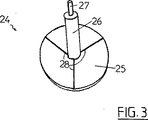
前記第1のロッド(26)において前記コイル(23)の前記貫通孔から離脱した位置にある他方の端部に連結される円板(25)とを有して構成され、
該円板(25)において前記コイル(23)に向く面には、燃料を通過させることができる少なくとも1つの溝(28)が放射方向に形成され、
前記プレート(21)と前記球(19)と前記バネ(18)とを有して構成される弾性手段が、前記アキュムレータ手段(2)内の圧力が所定の閾値を超えた際に、前記保存手段(12)内へ燃料を流入させることを特徴とする始動システム。 - 供給手段(3)が、前記アキュムレータ手段(2)に燃料を供給するポンプ(6)と、前記アキュムレータ手段(2)に向かって前記ポンプ(6)からの燃料のただ1つの循環方向を可能にする逆止弁(8)とを有することを特徴とする請求項1に記載のシステム(1)。
Applications Claiming Priority (2)
| Application Number | Priority Date | Filing Date | Title |
|---|---|---|---|
| FR0200250A FR2834535B1 (fr) | 2002-01-10 | 2002-01-10 | Systeme de demarrage pour moteur a combustion interne |
| PCT/FR2003/000032 WO2003058053A1 (fr) | 2002-01-10 | 2003-01-08 | Systeme de demarrage pour moteur a combustion interne |
Publications (2)
| Publication Number | Publication Date |
|---|---|
| JP2005514556A JP2005514556A (ja) | 2005-05-19 |
| JP4304075B2 true JP4304075B2 (ja) | 2009-07-29 |
Family
ID=8871222
Family Applications (1)
| Application Number | Title | Priority Date | Filing Date |
|---|---|---|---|
| JP2003558332A Expired - Fee Related JP4304075B2 (ja) | 2002-01-10 | 2003-01-08 | 内燃機関用始動装置 |
Country Status (8)
| Country | Link |
|---|---|
| US (1) | US7007672B2 (ja) |
| EP (1) | EP1463887B1 (ja) |
| JP (1) | JP4304075B2 (ja) |
| AT (1) | ATE389107T1 (ja) |
| DE (1) | DE60319670T2 (ja) |
| ES (1) | ES2301785T3 (ja) |
| FR (1) | FR2834535B1 (ja) |
| WO (1) | WO2003058053A1 (ja) |
Families Citing this family (6)
| Publication number | Priority date | Publication date | Assignee | Title |
|---|---|---|---|---|
| DE10222895A1 (de) * | 2002-05-23 | 2003-12-11 | Bosch Gmbh Robert | Hochdruckspeicher für Kraftstoffeinspritzsysteme mit integriertem Druckregelventil |
| EP2072809A1 (en) * | 2007-12-20 | 2009-06-24 | GM Global Technology Operations, Inc. | Combustion engine and start system therefore |
| DE102009061750B3 (de) | 2009-08-20 | 2021-09-09 | Ford Global Technologies, Llc | Schnellstart eines Common Rail-Systems |
| DE102012004935B4 (de) * | 2012-03-10 | 2021-09-02 | Volkswagen Aktiengesellschaft | Common-Rail |
| DE102013019730A1 (de) * | 2013-11-27 | 2015-05-28 | Alfred Luhmann | Brennstoffzumesseinrichtung |
| CN114673601B (zh) * | 2022-03-18 | 2023-03-28 | 东风商用车有限公司 | 柴油机启动的快速建压方法、装置、设备及可读存储介质 |
Family Cites Families (14)
| Publication number | Priority date | Publication date | Assignee | Title |
|---|---|---|---|---|
| DE2936853A1 (de) * | 1979-09-12 | 1981-04-02 | Robert Bosch Gmbh, 7000 Stuttgart | Elektromagnetisch betaetigbares ventil |
| JPH03157576A (ja) * | 1989-11-15 | 1991-07-05 | Aisin Aw Co Ltd | 三方電磁弁及びその製造方法 |
| US5074263A (en) * | 1990-02-02 | 1991-12-24 | Emerson Charles E | Stop/start control system for an internal combustion engine |
| US5529387A (en) * | 1994-09-06 | 1996-06-25 | Valcor Engineering Corporation | Solenoid operated discharging orifice shutoff valve |
| US5533707A (en) * | 1995-03-09 | 1996-07-09 | Flexon, Inc. | Check valve with internal longitudinally displaceable sleeve valve |
| JP3526119B2 (ja) * | 1995-12-28 | 2004-05-10 | 株式会社日本自動車部品総合研究所 | 筒内直接噴射機関の燃料圧力制御装置 |
| US5758865A (en) * | 1996-08-21 | 1998-06-02 | Kavlico Corporation | Fuel injection valve and engine including the same |
| JPH10274130A (ja) * | 1997-03-28 | 1998-10-13 | Zexel Corp | 蓄圧式燃料噴射装置 |
| US5839413A (en) | 1997-04-28 | 1998-11-24 | The Rexroth Corporation | Quick start HEUI system |
| JP2000186649A (ja) * | 1998-12-24 | 2000-07-04 | Isuzu Motors Ltd | 吐出量可変制御型高圧燃料ポンプ |
| JP3633388B2 (ja) * | 1999-08-04 | 2005-03-30 | トヨタ自動車株式会社 | 内燃機関の高圧燃料ポンプ制御装置 |
| JP3539302B2 (ja) * | 1999-09-09 | 2004-07-07 | トヨタ自動車株式会社 | 内燃機関の燃料供給装置 |
| US6273395B1 (en) * | 1999-10-12 | 2001-08-14 | Ford Global Tech. | Electronically actuated suction control valve assembly |
| US6234128B1 (en) * | 2000-03-13 | 2001-05-22 | General Motors Corporation | Fuel accumulator with pressure on demand |
-
2002
- 2002-01-10 FR FR0200250A patent/FR2834535B1/fr not_active Expired - Fee Related
-
2003
- 2003-01-08 JP JP2003558332A patent/JP4304075B2/ja not_active Expired - Fee Related
- 2003-01-08 WO PCT/FR2003/000032 patent/WO2003058053A1/fr active IP Right Grant
- 2003-01-08 US US10/500,962 patent/US7007672B2/en not_active Expired - Fee Related
- 2003-01-08 AT AT03712217T patent/ATE389107T1/de not_active IP Right Cessation
- 2003-01-08 EP EP03712217A patent/EP1463887B1/fr not_active Expired - Lifetime
- 2003-01-08 DE DE60319670T patent/DE60319670T2/de not_active Expired - Lifetime
- 2003-01-08 ES ES03712217T patent/ES2301785T3/es not_active Expired - Lifetime
Also Published As
| Publication number | Publication date |
|---|---|
| JP2005514556A (ja) | 2005-05-19 |
| ES2301785T3 (es) | 2008-07-01 |
| US20050000494A1 (en) | 2005-01-06 |
| FR2834535A1 (fr) | 2003-07-11 |
| FR2834535B1 (fr) | 2004-07-23 |
| EP1463887B1 (fr) | 2008-03-12 |
| ATE389107T1 (de) | 2008-03-15 |
| EP1463887A1 (fr) | 2004-10-06 |
| WO2003058053A1 (fr) | 2003-07-17 |
| DE60319670T2 (de) | 2009-04-02 |
| US7007672B2 (en) | 2006-03-07 |
| DE60319670D1 (de) | 2008-04-24 |
Similar Documents
| Publication | Publication Date | Title |
|---|---|---|
| JP5052656B2 (ja) | 高圧燃料供給ポンプと燃料供給システム | |
| US6651630B2 (en) | High pressure fuel pump | |
| CN100379951C (zh) | 发动机阀驱动系统和驱动发动机阀的方法 | |
| US7568469B2 (en) | Control device for a high-pressure fuel supply system using variable displacement fuel pump with reduced power consumption | |
| KR20040054601A (ko) | 커먼 레일 인젝터 | |
| CN102536564B (zh) | 用于汽油直喷发动机的高压燃料泵的电磁阀控制方法 | |
| US20090199820A1 (en) | Pressure control valve with limp-home and ventilation function | |
| JPH11218065A (ja) | ソレノイド制御燃料噴射装置 | |
| JP4304075B2 (ja) | 内燃機関用始動装置 | |
| US6705282B2 (en) | Method and apparatus to provide engine compression braking | |
| JP4154243B2 (ja) | 内燃機関のための燃料噴射弁 | |
| JP2003524725A (ja) | 内燃機関用燃料噴射系のインジェクタのためのコンパクト構造の二段式電磁弁 | |
| JP3145108B2 (ja) | 電磁弁、特に燃料噴射ポンプ用の電磁弁 | |
| KR100428159B1 (ko) | 차량의 보조브레이크 | |
| JPH1089194A (ja) | 燃料噴射システム用のバルブ | |
| JPH11508345A (ja) | 燃料ポンプおよびその作動方法 | |
| US20030111625A1 (en) | Magnetic valve for controlling an injection valve of an internal combustion engine | |
| RU2727950C2 (ru) | Двигатель внутреннего сгорания и автомобиль с таким двигателем | |
| KR102440010B1 (ko) | 차량용 압력조절밸브 | |
| JP2006299855A (ja) | 流体制御弁 | |
| US20040149944A1 (en) | Electromechanical valve actuator | |
| JP2003503629A (ja) | コモンレールインジェクタ | |
| JP4125816B2 (ja) | 内燃機関のための燃料噴射ユニット | |
| EP0892171A2 (en) | Servo controlled common rail injector | |
| EP2176575A1 (de) | Verfahren zur ansteuerung eines elektromagnetischen schaltventils |
Legal Events
| Date | Code | Title | Description |
|---|---|---|---|
| A621 | Written request for application examination |
Free format text: JAPANESE INTERMEDIATE CODE: A621 Effective date: 20060106 |
|
| A131 | Notification of reasons for refusal |
Free format text: JAPANESE INTERMEDIATE CODE: A131 Effective date: 20080812 |
|
| A521 | Request for written amendment filed |
Free format text: JAPANESE INTERMEDIATE CODE: A523 Effective date: 20081107 |
|
| TRDD | Decision of grant or rejection written | ||
| A01 | Written decision to grant a patent or to grant a registration (utility model) |
Free format text: JAPANESE INTERMEDIATE CODE: A01 Effective date: 20090331 |
|
| A01 | Written decision to grant a patent or to grant a registration (utility model) |
Free format text: JAPANESE INTERMEDIATE CODE: A01 |
|
| A61 | First payment of annual fees (during grant procedure) |
Free format text: JAPANESE INTERMEDIATE CODE: A61 Effective date: 20090427 |
|
| FPAY | Renewal fee payment (event date is renewal date of database) |
Free format text: PAYMENT UNTIL: 20120501 Year of fee payment: 3 |
|
| R150 | Certificate of patent or registration of utility model |
Free format text: JAPANESE INTERMEDIATE CODE: R150 |
|
| FPAY | Renewal fee payment (event date is renewal date of database) |
Free format text: PAYMENT UNTIL: 20130501 Year of fee payment: 4 |
|
| LAPS | Cancellation because of no payment of annual fees |