JP4291709B2 - Linear movement mechanism and transfer robot using the same - Google Patents
Linear movement mechanism and transfer robot using the same Download PDFInfo
- Publication number
- JP4291709B2 JP4291709B2 JP2004052902A JP2004052902A JP4291709B2 JP 4291709 B2 JP4291709 B2 JP 4291709B2 JP 2004052902 A JP2004052902 A JP 2004052902A JP 2004052902 A JP2004052902 A JP 2004052902A JP 4291709 B2 JP4291709 B2 JP 4291709B2
- Authority
- JP
- Japan
- Prior art keywords
- vertical axis
- link arm
- moving member
- moving
- link
- Prior art date
- Legal status (The legal status is an assumption and is not a legal conclusion. Google has not performed a legal analysis and makes no representation as to the accuracy of the status listed.)
- Expired - Fee Related
Links
- 230000007246 mechanism Effects 0.000 title claims description 204
- 238000012546 transfer Methods 0.000 title claims description 87
- 230000002452 interceptive effect Effects 0.000 claims description 7
- 238000000034 method Methods 0.000 description 26
- 230000008569 process Effects 0.000 description 26
- 230000003028 elevating effect Effects 0.000 description 19
- 230000001965 increasing effect Effects 0.000 description 13
- 230000005540 biological transmission Effects 0.000 description 12
- 230000004048 modification Effects 0.000 description 7
- 238000012986 modification Methods 0.000 description 7
- 230000009467 reduction Effects 0.000 description 7
- 238000004519 manufacturing process Methods 0.000 description 6
- 239000004973 liquid crystal related substance Substances 0.000 description 5
- 230000002093 peripheral effect Effects 0.000 description 5
- 239000000758 substrate Substances 0.000 description 4
- 239000011521 glass Substances 0.000 description 3
- 230000008859 change Effects 0.000 description 2
- 238000004891 communication Methods 0.000 description 2
- 230000000694 effects Effects 0.000 description 2
- 239000004065 semiconductor Substances 0.000 description 2
- 238000013461 design Methods 0.000 description 1
- 239000011796 hollow space material Substances 0.000 description 1
- 239000002245 particle Substances 0.000 description 1
- 230000000149 penetrating effect Effects 0.000 description 1
- 238000012545 processing Methods 0.000 description 1
- 230000001105 regulatory effect Effects 0.000 description 1
- 238000007789 sealing Methods 0.000 description 1
Images


Classifications
-
- H—ELECTRICITY
- H01—ELECTRIC ELEMENTS
- H01L—SEMICONDUCTOR DEVICES NOT COVERED BY CLASS H10
- H01L21/00—Processes or apparatus adapted for the manufacture or treatment of semiconductor or solid state devices or of parts thereof
- H01L21/67—Apparatus specially adapted for handling semiconductor or electric solid state devices during manufacture or treatment thereof; Apparatus specially adapted for handling wafers during manufacture or treatment of semiconductor or electric solid state devices or components ; Apparatus not specifically provided for elsewhere
- H01L21/677—Apparatus specially adapted for handling semiconductor or electric solid state devices during manufacture or treatment thereof; Apparatus specially adapted for handling wafers during manufacture or treatment of semiconductor or electric solid state devices or components ; Apparatus not specifically provided for elsewhere for conveying, e.g. between different workstations
- H01L21/67763—Apparatus specially adapted for handling semiconductor or electric solid state devices during manufacture or treatment thereof; Apparatus specially adapted for handling wafers during manufacture or treatment of semiconductor or electric solid state devices or components ; Apparatus not specifically provided for elsewhere for conveying, e.g. between different workstations the wafers being stored in a carrier, involving loading and unloading
- H01L21/67766—Mechanical parts of transfer devices
-
- B—PERFORMING OPERATIONS; TRANSPORTING
- B25—HAND TOOLS; PORTABLE POWER-DRIVEN TOOLS; MANIPULATORS
- B25J—MANIPULATORS; CHAMBERS PROVIDED WITH MANIPULATION DEVICES
- B25J9/00—Programme-controlled manipulators
- B25J9/02—Programme-controlled manipulators characterised by movement of the arms, e.g. cartesian coordinate type
- B25J9/04—Programme-controlled manipulators characterised by movement of the arms, e.g. cartesian coordinate type by rotating at least one arm, excluding the head movement itself, e.g. cylindrical coordinate type or polar coordinate type
- B25J9/041—Cylindrical coordinate type
- B25J9/042—Cylindrical coordinate type comprising an articulated arm
-
- B—PERFORMING OPERATIONS; TRANSPORTING
- B25—HAND TOOLS; PORTABLE POWER-DRIVEN TOOLS; MANIPULATORS
- B25J—MANIPULATORS; CHAMBERS PROVIDED WITH MANIPULATION DEVICES
- B25J9/00—Programme-controlled manipulators
- B25J9/10—Programme-controlled manipulators characterised by positioning means for manipulator elements
- B25J9/106—Programme-controlled manipulators characterised by positioning means for manipulator elements with articulated links
- B25J9/1065—Programme-controlled manipulators characterised by positioning means for manipulator elements with articulated links with parallelograms
-
- H—ELECTRICITY
- H01—ELECTRIC ELEMENTS
- H01L—SEMICONDUCTOR DEVICES NOT COVERED BY CLASS H10
- H01L21/00—Processes or apparatus adapted for the manufacture or treatment of semiconductor or solid state devices or of parts thereof
- H01L21/67—Apparatus specially adapted for handling semiconductor or electric solid state devices during manufacture or treatment thereof; Apparatus specially adapted for handling wafers during manufacture or treatment of semiconductor or electric solid state devices or components ; Apparatus not specifically provided for elsewhere
- H01L21/677—Apparatus specially adapted for handling semiconductor or electric solid state devices during manufacture or treatment thereof; Apparatus specially adapted for handling wafers during manufacture or treatment of semiconductor or electric solid state devices or components ; Apparatus not specifically provided for elsewhere for conveying, e.g. between different workstations
- H01L21/67739—Apparatus specially adapted for handling semiconductor or electric solid state devices during manufacture or treatment thereof; Apparatus specially adapted for handling wafers during manufacture or treatment of semiconductor or electric solid state devices or components ; Apparatus not specifically provided for elsewhere for conveying, e.g. between different workstations into and out of processing chamber
- H01L21/67742—Mechanical parts of transfer devices
-
- Y—GENERAL TAGGING OF NEW TECHNOLOGICAL DEVELOPMENTS; GENERAL TAGGING OF CROSS-SECTIONAL TECHNOLOGIES SPANNING OVER SEVERAL SECTIONS OF THE IPC; TECHNICAL SUBJECTS COVERED BY FORMER USPC CROSS-REFERENCE ART COLLECTIONS [XRACs] AND DIGESTS
- Y10—TECHNICAL SUBJECTS COVERED BY FORMER USPC
- Y10S—TECHNICAL SUBJECTS COVERED BY FORMER USPC CROSS-REFERENCE ART COLLECTIONS [XRACs] AND DIGESTS
- Y10S414/00—Material or article handling
- Y10S414/13—Handlers utilizing parallel links
-
- Y—GENERAL TAGGING OF NEW TECHNOLOGICAL DEVELOPMENTS; GENERAL TAGGING OF CROSS-SECTIONAL TECHNOLOGIES SPANNING OVER SEVERAL SECTIONS OF THE IPC; TECHNICAL SUBJECTS COVERED BY FORMER USPC CROSS-REFERENCE ART COLLECTIONS [XRACs] AND DIGESTS
- Y10—TECHNICAL SUBJECTS COVERED BY FORMER USPC
- Y10T—TECHNICAL SUBJECTS COVERED BY FORMER US CLASSIFICATION
- Y10T74/00—Machine element or mechanism
- Y10T74/20—Control lever and linkage systems
- Y10T74/20207—Multiple controlling elements for single controlled element
- Y10T74/20305—Robotic arm
Landscapes
- Engineering & Computer Science (AREA)
- Robotics (AREA)
- Manufacturing & Machinery (AREA)
- Physics & Mathematics (AREA)
- Condensed Matter Physics & Semiconductors (AREA)
- General Physics & Mathematics (AREA)
- Mechanical Engineering (AREA)
- Computer Hardware Design (AREA)
- Microelectronics & Electronic Packaging (AREA)
- Power Engineering (AREA)
- Manipulator (AREA)
- Container, Conveyance, Adherence, Positioning, Of Wafer (AREA)
- Transmission Devices (AREA)
Description
本願発明は、搬送ロボットに関し、より詳しくは、基板等の薄板状のワークを直線状に搬送することができる搬送ロボットに関する。 The present invention relates to a transfer robot, and more particularly to a transfer robot that can transfer a thin plate-like workpiece such as a substrate in a straight line.
搬送ロボットのうち、直線状の移動行程に沿ってハンドを移動させる機構(直線移動機構)をもつものは、いわゆる多関節型ロボットに比較して構成が簡単で安価であり、たとえば、半導体装置の製造工程、あるいは、液晶表示パネルの製造工程において、各処理室へのウエハ、あるいはガラス基板等の薄板状ワークの搬入あるいは搬出用のロボットとして多用されている。 Among transfer robots, a robot having a mechanism for moving a hand along a linear movement process (linear movement mechanism) is simpler and less expensive than a so-called articulated robot. In a manufacturing process or a manufacturing process of a liquid crystal display panel, it is frequently used as a robot for loading or unloading a wafer or a thin plate workpiece such as a glass substrate into each processing chamber.
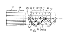
このような搬送ロボットにおける直線移動機構は、たとえば、特許文献1に示されるように、また、本願の図36に示すように、ベースに対して平行四辺形リンクを2つ組み合わせたものが一般的である。すなわち、図36に示した構成についていえば、ベースに固定されたベースプレート91に対し、軸O1を中心として第1主リンクアーム92が揺動可能に支持されるとともに、軸O2を中心として第1副リンクアーム93が揺動可能に支持されている。第1主リンクアーム92と第1副リンクアーム93の先端には、中間プレート96が軸O3および軸O4を中心として揺動可能に連結されて第1の平行四辺形リンクが形成される一方、中間プレート96には、第2主リンクアーム94が軸O3を中心として揺動可能に連結されるとともに軸O5を中心として第2副リンクアーム95が揺動可能に支持されている。第2主リンクアーム94と第2副リンクアーム95の先端には、移動プレート97が軸O6および軸O7を中心として揺動可能に連結された第2の平行四辺形リンクが形成される。移動プレート97には、薄板状ワークWを載置保持することができるハンド98が取付けられている。
A linear movement mechanism in such a transfer robot is generally a combination of two parallelogram links with respect to the base as shown in, for example,
このような構成によれば、2つの平行四辺形リンクが変形しても、移動プレート97ないしハンド98の方向は一定に維持される。また、第1主リンクアーム92および第2主リンクアーム94の長さは同じに設定されているとともに、第1主リンクアーム92には、これが軸O1を中心として回動するとき、この回動方向とは逆方向に倍の角速度で第2主リンクアーム94を軸O3を中心として回動させるための機構が内蔵されている。これにより、第1主リンクアーム92を回動駆動すると、移動プレート97ないしハンド98は、その方向性を一定に維持しながら、直線状の移動行程を移動する。
According to such a configuration, even if the two parallelogram links are deformed, the direction of the moving
ところで、最近においては、たとえば、半導体製造において取り扱うウエハの外径がますます大きくなり、また、液晶表示パネルの製造においても、パネルサイズが大きくなる傾向がある。それにともない、搬送ロボットにおけるハンドおよびこれに載置して搬送するべきワークの寸法が大きくなり、また、移動行程も長大化が求められている。そうすると、図36に示した2つの平行四辺形リンクを組み合わせた直線移動機構においては、とりわけリンクアームが伸長した状態において、ワークやこれを支持するハンドの重みがリンクアーム全体を上下方向に撓ませてしまうという傾向が生まれ、正確な直線移動行程を確保しづらくなるという問題が生じる。 By the way, recently, for example, the outer diameter of a wafer handled in semiconductor manufacturing has increased, and in the manufacture of a liquid crystal display panel, the panel size tends to increase. Along with this, the size of the hand in the transfer robot and the work to be placed and transferred is increased, and the length of the moving process is also required to be increased. Then, in the linear movement mechanism that combines the two parallelogram links shown in FIG. 36, the weight of the work and the hand that supports it deflects the entire link arm vertically, especially when the link arm is extended. As a result, there is a problem that it is difficult to secure an accurate linear movement process.
基本的な構成を変更することなくこの問題を解決するためには、各部の剛性をアップさせたり、軸受としてより精度のよい高価なものを採用せざるをえず、このことは、大幅なコストアップにつながる。また、リンク機構により所望の直線移動行程を実現する場合、基本的に、その移動行程が長大化するほど、コスト上昇を招くことなくその移動行程の正確な直線性を確保することが困難となる。たとえば図36に示される直線移動機構の場合、加熱されたワークWがハンド98に載置されると、このワークWからの輻射熱によって第2主リンクアーム94が第1主リンクアーム92よりも熱膨張しやすい。そうなると、第2主リンクアーム94と第1主リンクアーム92との長さに微妙な差が生じるため、直線状の移動行程に沿ってスムーズに移動できなくなる。また、移動行程の長さは、第1主リンクアーム92の長さと第2主リンクアーム94の長さによって変わるが、これらアームの長さを等しくする設計仕様では、一方のアームだけを長くするわけにいかず、移動行程を長くするには必ず両方のアームを長くしなければならない。
In order to solve this problem without changing the basic configuration, it is necessary to increase the rigidity of each part or to adopt a more accurate and expensive bearing, which is a significant cost. Leading up. Further, when a desired linear movement process is realized by the link mechanism, basically, as the movement process becomes longer, it becomes difficult to ensure accurate linearity of the movement process without increasing the cost. . For example, in the case of the linear movement mechanism shown in FIG. 36, when the heated workpiece W is placed on the
また、このような搬送ロボットは、半導体装置、あるいは液晶表示パネルの製造工程において、プロセスチャンバへワークを搬入し、あるいは搬出するために用いられる。たとえば、各プロセスチャンバへのワークの搬入、搬出は、大気搬送モジュールと各プロセスチャンバとの間に真空搬送モジュールを配置し、この真空搬送モジュールを介した搬送によって行われる。真空搬送モジュールは、周部に複数のプロセスチャンバが配置されたトランスポートチャンバと、大気搬送モジュールと上記トランスポートチャンバをつなぐロードロックとを備え、トランスポートチャンバ内に真空雰囲気下で作動可能なこの種の直進搬送ロボットが配置されて構成される。直進搬送ロボットは、ロードロック内のワークを受け取ってトランスポートチャンバ内に搬送し、そして、いずれかのプロセスチャンバ内にワークを搬入し、処理済みのワークをプロセスチャンバから受け取り、ロードロック内へ搬送するといった作動をする。 Further, such a transfer robot is used to carry a workpiece into or out of a process chamber in a manufacturing process of a semiconductor device or a liquid crystal display panel. For example, loading and unloading of workpieces to and from each process chamber is performed by placing a vacuum transfer module between the atmospheric transfer module and each process chamber and transferring the workpiece through the vacuum transfer module. The vacuum transfer module includes a transport chamber in which a plurality of process chambers are arranged at the periphery, and a load lock connecting the atmospheric transfer module and the transport chamber, and the vacuum transfer module is operable in a vacuum atmosphere in the transport chamber. A kind of straight-forward transfer robot is arranged. The straight transfer robot receives the work in the load lock and transfers it into the transport chamber, then loads the work into one of the process chambers, receives the processed work from the process chamber, and transfers it into the load lock. It operates like doing.
図36に示した搬送ロボットは、ハンドを1つだけ有しているものであるため、上記したような真空搬送モジュール内でのワークの搬送を効率良く行うには、難点があった。 Since the transfer robot shown in FIG. 36 has only one hand, there is a difficulty in efficiently transferring the workpiece in the vacuum transfer module as described above.
本願発明は、このような事情のもとで考え出されたものであって、簡単な構成により、より正確な直線移動行程を実現できる直線移動機構およびこれを用いた搬送ロボット、さらにはハンドを2つ備えることによってワークの搬送効率を高めた搬送ロボットを提供することをその課題としている。 The present invention has been conceived under such circumstances, and with a simple configuration, a linear movement mechanism capable of realizing a more accurate linear movement process, a transfer robot using the linear movement mechanism, and a hand. An object of the present invention is to provide a transfer robot that improves the transfer efficiency of workpieces by providing two.
上記の課題を解決するため、本願発明では、次の技術的手段を採用した。 In order to solve the above problems, the present invention employs the following technical means.
すなわち、本願発明の第1の側面によって提供される直線移動機構は、ガイド部材と、このガイド部材にスライド可能に支持され、このガイド部材上に設定された水平直線状の移動行程に沿って移動可能な移動部材と、この移動部材を駆動する駆動機構とを備えた直線移動機構であって、上記駆動機構は、上記ガイド部材における上記移動行程上またはその平行線上の第1垂直軸を中心として回動駆動される第1リンクアームと、上記移動行程上またはその平行線上の上記第1垂直軸と異なる第2垂直軸を中心として回動可能な副リンクアームと、上記第1リンクアームおよび副リンクアームが第3垂直軸および第4垂直軸を中心として相対回動可能に連結される中間リンクとを備えた平行四辺形リンク機構を含むとともに、上記中間リンクに対して上記第3垂直軸と第4垂直軸を通る直線上の第5垂直軸を中心として相対回動可能に一端が連結されるとともに、他端が上記移動部材に対して上記移動行程と交差する方向に移動可能とされた第6垂直軸を中心として回動可能に連結された第2リンクアームを含んでおり、上記第5垂直軸と上記第6垂直軸との軸間距離は、上記第1垂直軸と上記第3垂直軸との軸間距離と等しく設定されており、かつ、上記第1リンクアームと上記第2リンクアームとは、上記第1リンクアームが回動駆動されるとき、上記第2リンクアームと上記移動部材との連結部の軌跡が、上記水平直線状の移動行程と一致もしくは平行するように連携されていることを特徴としている。 That is, the linear movement mechanism provided by the first aspect of the present invention is supported along the guide member and the horizontal linear movement stroke that is slidably supported by the guide member and set on the guide member. A linear movement mechanism comprising a movable member capable of driving and a drive mechanism for driving the movement member, wherein the drive mechanism is centered on a first vertical axis on the movement stroke of the guide member or on a parallel line thereof. A first link arm that is rotationally driven; a sub-link arm that is rotatable about a second vertical axis that is different from the first vertical axis on the travel stroke or parallel lines thereof; the first link arm and the sub-link arm; The intermediate link includes a parallelogram link mechanism including a link arm having a third vertical axis and an intermediate link coupled to be rotatable about the fourth vertical axis. Together with the third pivotable relative end about a fifth vertical axis on a straight line passing through the vertical axis and the fourth vertical shaft is connected against, the other end intersects with the moving path relative to the moving member A second link arm that is pivotally connected about a sixth vertical axis that is movable in the direction of movement, and the inter-axis distance between the fifth vertical axis and the sixth vertical axis is When the first link arm and the second link arm are set to be equal to the distance between the first vertical axis and the third vertical axis and the first link arm is rotationally driven. , the locus of the connecting portion between the second link arm and the moving member is characterized by being cooperation to match or parallel to the horizontal linear movement stroke.
好ましい実施の形態においては、ガイド部材と、このガイド部材にスライド可能に支持され、このガイド部材上に設定された水平直線状の移動行程に沿って移動可能な移動部材と、この移動部材を駆動する駆動機構とを備えた直線移動機構であって、上記駆動機構は、上記ガイド部材における上記移動行程上またはその平行線上の第1垂直軸を中心として回動駆動される第1リンクアームと、上記移動行程上またはその平行線上の上記第1垂直軸と異なる第2垂直軸を中心として回動可能な副リンクアームと、上記第1リンクアームおよび副リンクアームが第3垂直軸および第4垂直軸を中心として相対回動可能に連結される中間リンクとを備えた平行四辺形リンク機構を含むとともに、上記中間リンクに対して上記第3垂直軸と第4垂直軸を通る直線上の第5垂直軸を中心として相対回動可能に一端が連結されるとともに、他端が上記移動部材に対して第6垂直軸を中心として回動可能に連結された第2リンクアームを含んでおり、上記第5垂直軸と上記第6垂直軸との軸間距離は、上記第1垂直軸と上記第3垂直軸との軸間距離と等しく設定されており、上記移動部材には、さらに別の補助移動部材が上記移動行程に沿って移動可能に支持されており、上記第2リンクアームは、上記補助移動部材に対し、上記第5垂直軸から第6垂直軸を通ってさらに延びる延長線上の第7垂直軸を中心として相対回動可能で、なおかつ上記第7垂直軸が上記移動行程と交差する方向に変位可能に連結されており、かつ、上記第1リンクアームと上記第2リンクアームとは、上記第1リンクアームが回動駆動されるとき、上記補助移動部材に対して上記第2リンクアームの回動軸となる上記第7垂直軸の軌跡が、上記移動行程に沿って弧線を描くように連携されている。 In a preferred embodiment, the guide member, a movable member supported by the guide member so as to be slidable and movable along a horizontal linear movement stroke set on the guide member, and the movable member are driven. A first link arm that is rotationally driven around a first vertical axis on the moving stroke or on a parallel line of the guide member; A sub-link arm that is rotatable about a second vertical axis that is different from the first vertical axis on the movement stroke or on a parallel line thereof, and the first link arm and the sub-link arm are a third vertical axis and a fourth vertical axis. A parallelogram link mechanism having an intermediate link coupled to be rotatable about a shaft, and the third vertical axis and the fourth vertical axis with respect to the intermediate link A second link arm having one end coupled to be rotatable about a fifth vertical axis on a straight line passing therethrough and the other end coupled to be rotatable about the sixth vertical axis with respect to the moving member The inter-axis distance between the fifth vertical axis and the sixth vertical axis is set equal to the inter-axis distance between the first vertical axis and the third vertical axis. Further, another auxiliary moving member is supported so as to be movable along the moving stroke, and the second link arm passes from the fifth vertical axis to the sixth vertical axis with respect to the auxiliary moving member. Further, the seventh vertical axis can be relatively rotated about a seventh vertical axis on the extended line, and the seventh vertical axis is connected so as to be displaceable in a direction crossing the moving stroke, and the first link arm and the above The second link arm is the first link arm. When the system is driven to rotate, the locus of the seventh vertical axis, which is the rotational axis of the second link arm, is linked to the auxiliary moving member so as to draw an arc line along the movement stroke. Yes.
好ましい実施の形態においてはまた、ガイド部材と、このガイド部材にスライド可能に支持され、このガイド部材上に設定された水平直線状の移動行程に沿って移動可能な移動部材と、この移動部材を駆動する駆動機構とを備えた直線移動機構であって、上記駆動機構は、上記ガイド部材における上記移動行程上またはその平行線上の第1垂直軸を中心として回動駆動される第1リンクアームと、上記移動行程上またはその平行線上の上記第1垂直軸と異なる第2垂直軸を中心として回動可能な副リンクアームと、上記第1リンクアームおよび副リンクアームが第3垂直軸および第4垂直軸を中心として相対回動可能に連結される中間リンクとを備えた平行四辺形リンク機構を含むとともに、上記中間リンクに対して上記第3垂直軸と第4垂直軸を通る直線上の第5垂直軸を中心として相対回動可能に一端が連結されるとともに、他端が上記移動部材に対して第6垂直軸を中心として回動可能に連結された第2リンクアームを含んでおり、上記第5垂直軸と上記第6垂直軸との軸間距離は、上記第1垂直軸と上記第3垂直軸との軸間距離と等しく設定されており、上記移動部材には、さらに別の補助移動部材が上記移動行程に沿って移動可能に支持されているとともに、上記平行四辺形リンク機構には、上記中間リンクより外側において、上記第1リンクアームおよび副リンクアームに第8垂直軸および第9垂直軸を中心として相対回動可能に連結された補助中間リンクが含まれており、この補助中間リンクには、上記第8垂直軸と第9垂直軸を通る直線上の第10垂直軸を中心として相対回動可能な第3リンクアームが連結されており、この第3リンクアームは、上記補助移動部材に対し、第11垂直軸を中心として相対回動可能に連結されており、かつ、上記第10垂直軸と上記第11垂直軸との軸間距離は、上記第1垂直軸と上記第8垂直軸との軸間距離と等しく設定されており、かつ、上記第1リンクアームと上記第2リンクアームとは、上記第1リンクアームが回動駆動されるとき、上記第2リンクアームと上記移動部材との連結部の軌跡が、上記水平直線状の移動行程と一致もしくは平行するように連携されているとともに、上記第1リンクアームと上記第3リンクアームとは、上記第1リンクアームが回動するとき、上記補助移動部材に対する上記第3リンクアームの回動軸となる上記第11垂直軸の軌跡が、上記水平直線状の移動行程と一致もしくは平行するように連携されている。 In a preferred embodiment, the guide member, a movable member that is slidably supported by the guide member, and is movable along a horizontal linear movement stroke set on the guide member; A linear movement mechanism including a driving mechanism for driving, wherein the driving mechanism is a first link arm that is rotationally driven around a first vertical axis on the movement stroke or a parallel line of the guide member; A sub-link arm rotatable about a second vertical axis different from the first vertical axis on the moving stroke or parallel lines thereof, and the first link arm and the sub-link arm include a third vertical axis and a fourth A parallelogram link mechanism having an intermediate link coupled to be rotatable relative to the vertical axis, and the third vertical axis and the fourth vertical link with respect to the intermediate link. A second end is connected to be rotatable relative to a fifth vertical axis on a straight line passing through the shaft, and the other end is connected to the moving member to be rotatable about a sixth vertical axis. A link arm is included, and an inter-axis distance between the fifth vertical axis and the sixth vertical axis is set equal to an inter-axis distance between the first vertical axis and the third vertical axis; the members, a further auxiliary moving member and that is movably supported along the movement path monitor, the said parallelogram link mechanism, the outer side of the intermediate link, the first link arm And an auxiliary intermediate link connected to the sub link arm so as to be relatively rotatable about the eighth vertical axis and the ninth vertical axis. The auxiliary intermediate link includes the eighth vertical axis and the ninth vertical axis. Centered on the 10th vertical axis on a straight line passing through the axis And third link arm capable rotationally is connected Te, the third link arm, to the auxiliary movable member are relatively rotatably connected about a first 11 shaft vertically, and, the The inter-axis distance between the tenth vertical axis and the eleventh vertical axis is set equal to the inter-axis distance between the first vertical axis and the eighth vertical axis , and the first link arm and the first vertical axis . The two-link arm means that when the first link arm is rotationally driven, the locus of the connecting portion between the second link arm and the moving member coincides with or is parallel to the horizontal linear movement stroke. The eleventh link arm and the third link arm are linked to each other and serve as a pivot axis of the third link arm with respect to the auxiliary moving member when the first link arm rotates. The vertical axis trajectory Are coordinated with or parallel to the horizontal linear travel .
上記構成の直線移動機構においては、移動部材は、その移動行程がガイド部材によって規定されており、また、補助移動部材も、その移動行程が移動部材によって規定されるので、その移動の直進性は高度に保たれる。すなわち、移動部材や補助移動部材の移動過程において、横方向または上下方向に位置がぶれるといったことは皆無となる。したがって、移動部材あるいは補助移動部材に設けられたハンドに載置されるワークの大きさあるいは重量に関係なく、このワークを正確な直進性をもって搬送することができる。 In the linear movement mechanism configured as described above, the movement stroke of the movement member is defined by the guide member, and the movement distance of the auxiliary movement member is also defined by the movement member. Highly maintained. That is, there is no possibility that the position of the moving member or the auxiliary moving member is shifted in the horizontal direction or the vertical direction. Therefore, regardless of the size or weight of the work placed on the hand provided on the moving member or the auxiliary moving member, the work can be conveyed with accurate straightness.
一方、上記移動部材を駆動するための駆動機構は、第1リンクアームと第2リンクアームとを含んだリンク機構によって構成されているが、このリンク機構は、単なるリンク機構ではなく、第1リンクアームの回動駆動に従動して、第2リンクアームと移動部材との連結点(第6垂直軸)の移動軌跡が上記ガイド部材によって設定された直線状の移動行程と一致または平行するように規制されている。これは、第2リンクアームの回動半径(第5垂直軸と第6垂直軸との軸間距離)と第1リンクアームの回動半径(第1垂直軸と第3垂直軸との軸間距離)とが等しいことによる。すなわち、この駆動機構は、それ自体、移動部材を移動行程にそって移動させることができるように構成されている。したがって、第1リンクアームと第2リンクアームとが重なる、いわゆる思案点付近において移動部材の移動が不安定になるといった問題は生じえない。 On the other hand, the drive mechanism for driving the moving member is constituted by a link mechanism including a first link arm and a second link arm, but this link mechanism is not a simple link mechanism but a first link. As the arm is driven to rotate, the movement trajectory of the connecting point (sixth vertical axis) between the second link arm and the moving member coincides with or parallel to the linear movement stroke set by the guide member. It is regulated. This is because the rotation radius of the second link arm (the distance between the fifth vertical axis and the sixth vertical axis) and the rotation radius of the first link arm (between the first vertical axis and the third vertical axis) The distance) is equal. That is, the drive mechanism itself is configured to be able to move the moving member along the moving stroke. Therefore, the problem that the movement of the moving member becomes unstable near the so-called thought point where the first link arm and the second link arm overlap with each other cannot occur.
このような移動の安定性は、第2リンクアームと移動部材との連結点(第6垂直軸)が移動行程と交差する方向に変位可能な構成でも同様に得られる。特にこのような構成によれば、第2リンクアームの長さ(第5垂直軸と第6垂直軸との軸間距離)と第1リンクアームの長さ(第1垂直軸と第3垂直軸との軸間距離)とが熱膨張などによって多少異なる状態となっても、移動部材が思案点付近でもスムーズに移動する。また、第2リンクアームに第7垂直軸を介して連結された補助移動部材や、あるいは第3リンクアームを介して連結された補助移動部材がある場合でも、上記移動部材と同様に移動の安定性がもたらされる。特にこのような構成によれば、移動部材と補助移動部材とが連動して同方向に移動するため、ワークの移動距離をより長くすることができる。 Such movement stability can be obtained in the same manner even in a configuration in which the connecting point (sixth vertical axis) between the second link arm and the moving member can be displaced in the direction intersecting the moving stroke. In particular, according to such a configuration, the length of the second link arm (the distance between the fifth vertical axis and the sixth vertical axis) and the length of the first link arm (the first vertical axis and the third vertical axis). Even if the distance between the two axes is slightly different due to thermal expansion or the like, the moving member moves smoothly even near the thought point. In addition, even when there is an auxiliary moving member connected to the second link arm via the seventh vertical shaft or an auxiliary moving member connected via the third link arm, the movement is stable as in the case of the moving member. Sex is brought. In particular, according to such a configuration, since the moving member and the auxiliary moving member move in the same direction in conjunction with each other, the moving distance of the workpiece can be further increased.
上記駆動機構は、それ自体移動部材さらには補助移動部材を直線状の移動行程にそって移動させることができるものではあるが、移動部材の最終的な移動直線性は上記したようにガイド部材によって達成され、補助移動部材の移動直線性も移動部材を介して間接的にガイド部材によって達成される。また、移動部材や補助移動部材、これに載置されるワークの重量もまた、実質的にガイド部材によって支持される。したがって、この駆動機構は、求められる部材強度あるいは各部の精度が低くてよく、低コストで製作することができる。 Although the drive mechanism itself can move the moving member and further the auxiliary moving member along the linear movement stroke, the final moving linearity of the moving member is determined by the guide member as described above. The movement linearity of the auxiliary moving member is also achieved by the guide member indirectly via the moving member. Further, the weight of the moving member, the auxiliary moving member, and the work placed thereon is also substantially supported by the guide member. Therefore, this drive mechanism can be manufactured at low cost because the required member strength or accuracy of each part may be low.
他の好ましい実施の形態においては、ガイド部材と、このガイド部材にスライド可能に支持され、このガイド部材上に設定された水平直線状の移動行程に沿って移動可能な移動部材と、この移動部材を駆動する駆動機構とを備えた直線移動機構であって、上記駆動機構は、上記ガイド部材における上記移動行程上またはその平行線上の第1垂直軸を中心として回動駆動される第1リンクアームと、上記移動行程上またはその平行線上の上記第1垂直軸と異なる第2垂直軸を中心として回動可能な副リンクアームと、上記第1リンクアームおよび副リンクアームが第3垂直軸および第4垂直軸を中心として相対回動可能に連結される中間リンクとを備えた平行四辺形リンク機構を含むとともに、上記中間リンクに対して上記第3垂直軸と第4垂直軸を通る直線上の第5垂直軸を中心として相対回動可能に一端が連結されるとともに、他端が上記移動部材に対して上記移動行程と交差する方向に移動可能とされた第6垂直軸を中心として回動可能に連結された第2リンクアームを含んでおり、上記第5垂直軸と上記第6垂直軸との軸間距離は、上記第1垂直軸と上記第3垂直軸との軸間距離より大きく設定されており、かつ、上記第1リンクアームと上記第2リンクアームとは、上記第1リンクアームが回動駆動されるとき、上記第2リンクアームと上記移動部材との連結部の軌跡が、上記水平直線状の移動行程に沿って弧線を描くように連携されている。 In another preferred embodiment, the guide member, a moving member that is slidably supported by the guide member and is movable along a horizontal linear movement stroke set on the guide member, and the moving member A first link arm that is rotationally driven about a first vertical axis on the movement stroke or on a parallel line of the guide member. A sub-link arm that is rotatable about a second vertical axis that is different from the first vertical axis on the moving stroke or parallel lines thereof, and the first link arm and the sub-link arm are connected to a third vertical axis and a first 4 parallelogram linkage-containing Mutotomoni with an intermediate link about a vertical axis is connected relatively rotatably, said third vertical axis and the fourth vertical with respect to the intermediate link A sixth vertical axis whose one end is connected to be rotatable relative to a fifth vertical axis on a straight line passing through the axis, and whose other end is movable in a direction intersecting the moving stroke with respect to the moving member. axis includes a second link arm pivotally connected around a center distance between the fifth vertical axis and the sixth vertical axis, and said first vertical axis and the third vertical axis And the first link arm and the second link arm are configured such that when the first link arm is driven to rotate, the second link arm and the moving member are Are linked so as to draw an arc along the horizontal linear movement stroke .
このような直線移動機構によっても、上記と同様の効果を得ることができる。すなわち、第2リンクアームの回動半径(第5垂直軸と第6垂直軸との軸間距離)が第1リンクアームの回動半径(第1垂直軸と第3垂直軸との軸間距離)より大きい構成においては、第2リンクアームと移動部材との連結点(第6垂直軸)が移動行程と交差する方向に変位可能となっている。これにより、上記連結点の移動軌跡が上記移動行程に沿って弧線を描くため、駆動機構は、移動部材を移動行程にそって移動させることができる。したがって、第1リンクアームと第2リンクアームとが重なる、いわゆる思案点付近において移動部材の移動が不安定になるといった問題は生じえない。特にこのような構成によれば、第2リンクアームの長さが第1リンクアームの長さに制約されずに長く設定できるため、移動行程に沿ってワークを移動させる距離をより長くすることができる。 Even with such a linear movement mechanism, the same effects as described above can be obtained. That is, the turning radius of the second link arm (the distance between the fifth vertical axis and the sixth vertical axis) is the turning radius of the first link arm (the distance between the first vertical axis and the third vertical axis). In a larger configuration, the connecting point (sixth vertical axis) between the second link arm and the moving member can be displaced in a direction intersecting the moving stroke. Thereby, since the movement locus | trajectory of the said connection point draws an arc line along the said movement stroke, the drive mechanism can move a moving member along a movement stroke. Therefore, the problem that the movement of the moving member becomes unstable near the so-called thought point where the first link arm and the second link arm overlap with each other cannot occur. In particular, according to such a configuration, since the length of the second link arm can be set longer without being restricted by the length of the first link arm, the distance for moving the workpiece along the moving stroke can be further increased. it can.
好ましい実施の形態においてはまた、上記第1リンクアームには、上記第3垂直軸上に中心をもつ第1ギアが固定されているとともに、上記第2リンクアームには、上記第5垂直軸上に中心をもつとともに上記第1ギアと噛み合い、かつこれと同径の第2ギアが固定されている。 In a preferred embodiment, a first gear having a center on the third vertical axis is fixed to the first link arm, and the second link arm has a fifth gear on the fifth vertical axis. A second gear having a center and meshing with the first gear and having the same diameter as the first gear is fixed.
他の好ましい実施の形態においては、上記第1リンクアームには、上記第3垂直軸上に中心をもつ第1ギアと上記第8垂直軸上に中心をもつ第3ギアとが固定されているとともに、上記第2リンクアームには、上記第5垂直軸上に中心をもつとともに上記第1ギアと噛み合い、かつこれと同径の第2ギアが固定されており、上記第3リンクアームには、上記第10垂直軸上に中心をもつとともに上記第3ギアと噛み合い、かつこれと同径の第4ギアが固定されている。 In another preferred embodiment, a first gear centered on the third vertical axis and a third gear centered on the eighth vertical axis are fixed to the first link arm. A second gear having a center on the fifth vertical axis and meshing with the first gear and having the same diameter as the second link arm is fixed to the second link arm. A fourth gear having a center on the tenth vertical axis and meshing with the third gear and having the same diameter as the third gear is fixed.
このような構成によれば、ギア列によって第1リンクアームと第2リンクアーム、さらには第1リンクアームと第3リンクアームとを連動させることができる。 According to such a configuration, the first link arm and the second link arm, and further the first link arm and the third link arm can be interlocked by the gear train.
好ましい実施の形態においてはまた、上記第1リンクアームには、上記第3垂直軸上に中心をもつ第1間欠ギアが固定されているとともに、上記第2リンクアームには、上記第5垂直軸上に中心をもつとともに上記第1間欠ギアと一時的に噛み合う第2間欠ギアが固定されている。 In a preferred embodiment, the first link arm is fixed with a first intermittent gear having a center on the third vertical axis, and the second link arm has the fifth vertical axis. A second intermittent gear having a center at the top and temporarily meshing with the first intermittent gear is fixed.
他の好ましい実施の形態においては、上記第1リンクアームには、上記第3垂直軸上に中心をもつ第1間欠ギアと上記第8垂直軸上に中心をもつ第3間欠ギアとが固定されているとともに、上記第2リンクアームには、上記第5垂直軸上に中心をもつとともに上記第1間欠ギアと一時的に噛み合う第2間欠ギアが固定されており、上記第3リンクアームには、上記第10垂直軸上に中心をもつとともに上記第3間欠ギアと一時的に噛み合う第4間欠ギアが固定されている。 In another preferred embodiment, a first intermittent gear centered on the third vertical axis and a third intermittent gear centered on the eighth vertical axis are fixed to the first link arm. The second link arm is fixed with a second intermittent gear having a center on the fifth vertical axis and temporarily meshing with the first intermittent gear. A fourth intermittent gear having a center on the tenth vertical axis and temporarily meshing with the third intermittent gear is fixed.
このような構成によれば、第1間欠ギアと第2間欠ギア、さらには第3間欠ギアと第4間欠ギアとを思案点付近において噛み合うように設定することにより、第1リンクアームと第2リンクアーム、さらには第1リンクアームと第3リンクアームとを思案点付近でも連動させることができる。 According to such a configuration, by setting the first intermittent gear and the second intermittent gear, and further, the third intermittent gear and the fourth intermittent gear so as to mesh in the vicinity of the thought point, the first link arm and the second intermittent gear are set. The link arm, and further, the first link arm and the third link arm can be interlocked even near the thought point.
本願発明の第2の側面によって提供される搬送ロボットは、上記第1の側面に係る直線移動機構が固定ベースに対し、上記移動行程上における鉛直状の旋回軸を中心として上記ガイド部材が旋回しうるように支持されているとともに、上記移動部材または補助移動部材には、板状ワークを載置しうるハンドが設けられていることを特徴としている。 In the transfer robot provided by the second aspect of the present invention, the linear movement mechanism according to the first aspect rotates the guide member around a vertical rotation axis on the movement stroke with respect to the fixed base. The moving member or the auxiliary moving member is provided with a hand on which a plate-like workpiece can be placed.
好ましい実施の形態においては、上記直線移動機構はまた、上記固定ベースに対し、上記旋回軸に沿って昇降しうるように支持されている。 In a preferred embodiment, the linear movement mechanism is also supported so as to be able to move up and down along the pivot axis with respect to the fixed base.
この搬送ロボットについても、直線移動機構について上記した利点を享受することができることは明らかであり、ワークの大きさや重量に関わらず、正確な直進性をもってこのワークを搬送することができ、しかも、コスト低減が可能である。 It is clear that this transfer robot can also enjoy the advantages described above with respect to the linear movement mechanism, and can transfer the workpiece with accurate straightness regardless of the size and weight of the workpiece, and it can be cost effective. Reduction is possible.
好ましい実施の形態においてはまた、上記直線移動機構は、上記固定ベースに対して上記旋回軸を中心として旋回可能な旋回ベースに設けられており、上記移動部材は、上記移動行程に沿って相互に干渉することなく移動可能に上記ガイド部材に支持された第1移動部材および第2移動部材を含んでいるとともに、上記駆動機構は、上記第1移動部材および第2移動部材をそれぞれ駆動するように上記旋回ベースに設けられた第1駆動機構および第2駆動機構を含んでいる。 In a preferred embodiment, the linear moving mechanism is provided on a turning base that can turn around the turning axis with respect to the fixed base, and the moving members are mutually connected along the moving stroke. The first moving member and the second moving member supported by the guide member so as to be movable without interference are included, and the driving mechanism drives the first moving member and the second moving member, respectively. A first drive mechanism and a second drive mechanism provided on the turning base are included.
このような搬送ロボットによれば、直線移動機構について上記した利点を享受することができるのはもちろん、第1移動部材および第2移動部材によってそれぞれワークを搬送させることができ、ワークの搬送効率を高めることができる。 According to such a transfer robot, not only can the above-described advantages of the linear moving mechanism be enjoyed, but also the workpiece can be transferred by the first moving member and the second moving member, respectively, and the transfer efficiency of the workpiece can be improved. Can be increased.
好ましい実施の形態においてはまた、上記第1駆動機構および上記第2駆動機構は、上記移動行程に対して対称に配置されている。 In a preferred embodiment, the first drive mechanism and the second drive mechanism are arranged symmetrically with respect to the moving stroke.
好ましい実施の形態においては、上記ガイド部材には、上記第1移動部材を移動可能に支持し、上記移動行程を挟んで位置する一対の第1ガイドレールと、上記第2移動部材を移動可能に支持し、上記一対の第1ガイドレールの外側において上記移動行程を挟んで位置する一対の第2ガイドレールとを備えている。 In a preferred embodiment, the guide member movably supports the first moving member, and the pair of first guide rails positioned on the movement stroke and the second moving member are movable. And a pair of second guide rails that are located outside the pair of first guide rails and sandwich the movement stroke.
これらの構成においては、第1移動部材と第2移動部材とは、いずれも一対のガイドレールによって安定的に支持され、しかも、平面視において、同一の移動行程を移動することができるようになる。第2の側面に係る搬送ロボットは、水平直線状の移動行程をもつ2つの移動部材およびこれらに支持されたハンドを備えた、ワークの効率的な搬送が可能なものであるが、上記のように2つの移動部材の移動行程が平面視において同一とすることにより、いずれの移動部材およびハンドによっても、平面的に同一の搬送先へのハンドの位置付け、平面的に同一の搬送元へのハンドの位置づけを正確に行うことができる。 In these configurations, the first moving member and the second moving member are both stably supported by the pair of guide rails, and can move in the same moving stroke in plan view. . The transfer robot according to the second aspect includes two moving members having a horizontal linear movement stroke and a hand supported by the moving members, and is capable of efficiently transferring a workpiece. In addition, since the movement strokes of the two moving members are the same in plan view, the position of the hand to the same transport destination in the plane and the hand to the same transport source in the plane can be obtained by any moving member and hand. Can be accurately positioned.
好ましい実施の形態においてはまた、上記第1移動部材および上記第2移動部材は、それぞれ、ハンドの基部を支持するハンド支持部を備えている一方、上記第2移動部材のハンド支持部は、上記第1移動部材のハンド支持部より上位に位置しているとともに、上記第2移動部材は、そのハンド支持部の両側部から上記第1移動部材のハンド支持部の両側部を迂回して延びる一対の支持アームを介して上記一対の第2ガイドレールに支持されている。 In a preferred embodiment, the first moving member and the second moving member each include a hand support portion that supports a base portion of the hand, while the hand support portion of the second moving member is A pair of second moving members that are positioned higher than the hand supporting portion of the first moving member, and that extend from both side portions of the hand supporting portion so as to bypass both side portions of the hand supporting portion of the first moving member. Are supported by the pair of second guide rails via the support arms.
このような構成によれば、第1移動部材と第2移動部材とを、互いに干渉することなく、平面視において同一の直線状移動行程を移動するように都合よく直線移動機構に支持させることができる。また、第2移動部材のハンド支持部は、一対の支持アームによって両持ち状に一対の第2ガイドレールに支持されるので、この第2移動部材によるワークの支持安定性がより高まる。なお、第1移動部材は、そのハンド支持部が第2移動部材のハンド支持部より下位に位置しているので、第2移動部材のような迂回状のアームを用いなくとも、安定的に一対の第1ガイドレールに支持される。 According to such a configuration, the first moving member and the second moving member can be conveniently supported by the linear movement mechanism so as to move in the same linear movement process in plan view without interfering with each other. it can. In addition, since the hand support portion of the second moving member is supported by the pair of second guide rails in a paired manner by the pair of support arms, the support stability of the workpiece by the second moving member is further increased. Note that the first moving member has a hand supporting portion positioned below the hand supporting portion of the second moving member, and therefore, a pair of the first moving members can be stably formed without using a detour arm like the second moving member. The first guide rail is supported.
好ましい実施の形態においてはさらに、上記第1移動部材は、上記一対の第2ガイドレールの内側において、上記ガイド部材を貫通して延びる連結アームを備え、この連結アームを介して上記第1駆動機構の第2リンクアームに連結されている一方、上記第2移動部材は、上記一対の支持アームの適部において上記第2駆動機構の第2リンクアームに連結されている。 In a preferred embodiment, the first moving member further includes a connecting arm extending through the guide member inside the pair of second guide rails, and the first driving mechanism is connected to the first moving member via the connecting arm. On the other hand, the second moving member is connected to the second link arm of the second drive mechanism at an appropriate portion of the pair of support arms.
このように構成することにより、上記のように第2移動部材を迂回状の一対の支持アームを介して第2ガイドレールに支持させたとしても、第1移動部材と第2移動部材とを、互いに干渉することなく、移動行程に沿って、上記第1駆動機構と第2駆動機構とによって不都合なく駆動することができる。 By configuring in this way, even if the second moving member is supported on the second guide rail via a pair of detouring support arms as described above, the first moving member and the second moving member are The first drive mechanism and the second drive mechanism can be driven without inconvenience along the movement stroke without interfering with each other.
好ましい実施の形態においてはまた、上記補助移動部材は、上記第2移動部材に支持されており、上記第1移動部材および上記補助移動部材は、それぞれ、ハンドの基部を支持するハンド支持部を備えている一方、上記補助移動部材のハンド支持部は、上記第1移動部材のハンド支持部より上位に位置しているとともに、上記補助移動部材を支持する上記第2移動部材は、その両側部から上記第1移動部材のハンド支持部の両側部を迂回して延びる一対の支持アームを介して上記一対の第2ガイドレールに支持されている。 In a preferred embodiment, the auxiliary moving member is supported by the second moving member, and each of the first moving member and the auxiliary moving member includes a hand support portion that supports the base of the hand. On the other hand, the hand supporting portion of the auxiliary moving member is positioned higher than the hand supporting portion of the first moving member, and the second moving member that supports the auxiliary moving member is from both sides thereof. The first moving member is supported by the pair of second guide rails via a pair of support arms that extend around both sides of the hand support portion.
このような構成によれば、第1移動部材と補助移動部材とを、互いに干渉することなく、平面視において同一の直線状移動行程を移動するように都合よく直線移動機構に支持させることができる。また、補助移動部材のハンド支持部は、直接的には第2移動部材に支持されるものの、間接的には一対の支持アームによって第2ガイドレールに支持されるので、この補助移動部材によるワークの支持安定性がより高まる。なお、第1移動部材は、そのハンド支持部が補助移動部材のハンド支持部より下位に位置しているので、迂回状のアームを用いなくとも、安定的に一対の第1ガイドレールに支持される。 According to such a configuration, the first moving member and the auxiliary moving member can be conveniently supported by the linear movement mechanism so as to move in the same linear movement process in plan view without interfering with each other. . In addition, although the hand support portion of the auxiliary moving member is directly supported by the second moving member, it is indirectly supported by the second guide rail by the pair of support arms. Support stability of the is further increased. The first moving member is supported by the pair of first guide rails stably without using a detour arm because the hand supporting portion is positioned below the hand supporting portion of the auxiliary moving member. The
好ましい実施の形態においてはさらに、上記第1移動部材は、上記一対の第2ガイドレールの内側において、上記ガイド部材を貫通して延びる連結アームを備え、この連結アームを介して上記第1駆動機構の第2リンクアームに連結されている一方、上記第2移動部材は、上記一対の支持アームの適部において上記第2駆動機構の第2リンクアームに連結されており、かつ、上記補助移動部材は、上記移動行程と交差する方向に長手状の案内溝を介して上記第2駆動機構の第2リンクアームに連結されている。 In a preferred embodiment, the first moving member further includes a connecting arm extending through the guide member inside the pair of second guide rails, and the first driving mechanism is connected to the first moving member via the connecting arm. The second moving member is connected to the second link arm of the second drive mechanism at an appropriate portion of the pair of support arms, and the auxiliary moving member is connected to the second link arm. Is connected to the second link arm of the second drive mechanism via a longitudinal guide groove in a direction crossing the moving stroke.
このように構成することにより、上記のように第2移動部材を迂回状の一対の支持アームを介して第2ガイドレールに支持させたとしても、この第2移動部材に支持された補助移動部材を支障なく移動行程に沿って移動させることができ、しかも、第2移動部材と補助移動部材とが連動して同方向に移動するため、ワークの移動距離をより長くすることができる。 With this configuration, even if the second moving member is supported by the second guide rail via the pair of detouring support arms as described above, the auxiliary moving member supported by the second moving member. Since the second moving member and the auxiliary moving member move in the same direction in conjunction with each other, the moving distance of the workpiece can be further increased.
本願発明のその他の特徴および利点は、図面を参照して以下に行う詳細な説明から、より明らかとなろう。 Other features and advantages of the present invention will become more apparent from the detailed description given below with reference to the drawings.
以下、本願発明に係る直線移動機構およびこれを用いた搬送ロボットの好ましい実施形態につき、図面を参照しつつ具体的に説明する。 Hereinafter, preferred embodiments of a linear movement mechanism according to the present invention and a transfer robot using the linear movement mechanism will be specifically described with reference to the drawings.
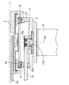
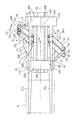
図1ないし図9は、本願発明の第1の実施形態に係る搬送ロボットを示している。図1、図2および図3に表れているように、第1の実施形態に係る搬送ロボットAは、概して、固定ベース5に対して第1垂直軸O1を中心に旋回可能かつ昇降可能に支持された直線移動機構Bを備えている。この直線移動機構Bは、概して、テーブル状をしたガイド部材1と、このガイド部材1上に設定された水平直線状の移動行程に沿って移動可能な移動部材2と、この移動部材2を所定方向に移動させるための駆動機構3とを備えている。移動部材2には、たとえば、液晶パネル用のガラス基板等、薄板状のワークWを載置保持しうるハンド4が取付けられている。
1 to 9 show a transfer robot according to a first embodiment of the present invention. As shown in FIGS. 1, 2, and 3, the transfer robot A according to the first embodiment is generally supported with respect to the fixed
図4、図5に表れているように、固定ベース5には、上記第1垂直軸O1を軸心にもつ円筒状の昇降軸51が回転不能かつ昇降可能に支持されているとともに、この昇降軸51の中心貫通孔には、同じく上記第1垂直軸O1を軸心にもつ円筒状の旋回部材52がベアリング52aを介して軸転可能に支持されており、さらに、この旋回部材52の中心貫通孔には、同じく上記第1垂直軸O1を軸心にもつ駆動軸53がベアリング53aを介して軸転可能に支持されている。昇降軸51は、図示しないアクチュエータによって昇降させられる。旋回部材52は、モータ等の図示しない回転アクチュエータによって固定ベース5に対して相対的に回転させられる。駆動軸53は、モータ等の図示しない回転アクチュエータによって上記旋回部材52に対して相対的に回転させられる。
As shown in FIGS. 4 and 5, a
上記ガイド部材1は、図2に表れているように、平面視長矩形状をしているとともに、図4に表れているように、底壁11と、この底壁11の両側縁部に形成された左右の起立壁12とを備えており、各起立壁12の上面には、それぞれガイドレール13が取付けられている。これらのガイドレール13には、移動部材2の下面に取付けたスライダ14が案内支持され、これにより、移動部材2は、ガイド部材1上に設定された水平直線状の移動行程GLに沿って移動することができる。本実施形態においてこの移動行程GLは、ガイド部材1の中心線に沿って設定されている。なお、移動行程GLと上記第1垂直軸O1との関係は、移動行程GL上に第1垂直軸O1が位置する関係とされている。
The
上記ガイド部材1の長手方向中央における底壁11には、貫通孔11aが形成されており、この貫通孔11aには段上げされた取付けフランジ16を有するブラケット15が嵌合固定されている。このガイド部材1は、上記ブラケット15の取付けフランジ16を介して、上記旋回部材52の上端に固定されている。これにより、旋回部材52を駆動すると、ガイド部材1およびこれに搭載された部材は、上記第1垂直軸O1を中心として旋回させられることになる。
A through hole 11a is formed in the
上記移動部材2を移動させるための駆動機構3は、この実施形態では、次のようにして構成されている。
In this embodiment, the
この駆動機構3は、上記駆動軸53の上端に一端が固定され、したがって、上記駆動軸53の駆動によって上記第1垂直軸O1を中心として回動駆動される第1リンクアーム31と、ガイド部材1における上記移動行程GL上であって上記第1垂直軸O1とは異なる第2垂直軸O2を中心として回動可能な副リンクアーム32と、これら第1リンクアーム31および副リンクアーム32が第3垂直軸O3および第4垂直軸O4を中心として相対回動可能に連結される中間リンク33とを備えた平行四辺形リンク機構3Aを備えている。第1垂直軸O1と第3垂直軸O3の軸間距離は、第2垂直軸O2と第4垂直軸O4の軸間距離と等しく、第1垂直軸O1と第2垂直軸O2の軸間距離は、第3垂直軸O3と第4垂直軸O4の軸間距離と等しい。
The
図2に表れているように、上記平行四辺形リンク機構3Aは、中間リンク33がガイド部材1の一側方に位置するように構成されており、第1リンクアーム31および副リンクアーム32は、図4、図6に表れているように、ガイド部材1の一方の起立壁12に形成したスリット12aを通ってガイド部材1の側方に延出させられている。副リンクアーム32は、具体的には、図6に表れているように、ガイド部材1の底壁11に取付けた固定軸11bに対し、ベアリング32aを介して回動可能に支持されている。
As shown in FIG. 2, the
第1リンクアーム31を回動駆動すると、平行四辺形リンク機構3Aは変形するが、中間リンク33の方向、すなわち、上記第3垂直軸O3と第4垂直軸O4を結ぶ直線の方向は、常に上記移動行程GLと平行になる。
When the
次にこの駆動機構3は、上記平行四辺形リンク機構3Aの中間リンク33における、上記第3垂直軸O3と第4垂直軸O4を通る直線上に位置する第5垂直軸O5を中心として相対回動可能な第2リンクアーム34を備えているとともに、第1リンクアーム31に固定され、かつ上記第3垂直軸O3上に中心をもつ第1ギア31aと、第2リンクアーム34に固定され、かつ上記第5垂直軸O5上に中心をもつ第2ギア34aとを備えている。これら第1ギア31aと第2ギア34aとは互いに噛み合わされており、かつ、同径のギアである。
Next, the
より具体的には、図7に良く表れているように、中間リンク33は、第1リンクアーム31および副リンクアーム32を上下から挟むように配置された2枚のリンクプレート33a,33bからなっており、第1リンクアーム31および副リンクアーム32にそれぞれ固定状に設けた軸体31b,32bの上下部に各リンクプレート33a,33bに設けた孔をベアリング31c,31d,32c,32dを介して嵌合させ、これにより、第1リンクアーム31と副リンクアーム32の中間リンク33に対する連結を図っている。なお、もちろん、各軸体31b,32bの軸心は、上記第3垂直軸O3および第4垂直軸O4と対応させられている。また、中間リンク33の各リンクプレート33a,33bを貫通するようにして、ベアリング34c,34dを介して上記第5垂直軸O5と対応する軸心をもつ軸体34bが回転可能に支持され、この軸体34bの上端に、上記第2リンクアーム34の一端が連結固定されている。上記第3垂直軸O3と対応する軸体31bおよび上記第5垂直軸O5と対応する軸体34bの下端部は、中間リンク33の下側のリンクプレート33bよりさらに下方に突出させられており、これらの突出部に、それぞれ上記の第1ギア31aおよび第2ギア34aが取付けられている。
More specifically, as clearly shown in FIG. 7, the
上記第2リンクアーム34の他端部は、上記移動部材2に対し、第6垂直軸O6を中心として相対回動可能に連結されている。この第6垂直軸O6は、上記移動行程GL上に位置し、かつ、第2リンクアーム34の長さ、すなわち、第5垂直軸O5と第6垂直軸O6の軸間距離は、第1リンクアーム31の長さ、すなわち、第1垂直軸O1と第3垂直軸O3の軸間距離と等しくなっている。
The other end of the
次に、上記構成を備える搬送ロボットAの動作について、説明する。 Next, the operation of the transfer robot A having the above configuration will be described.
前述したように、第1リンクアーム31を第1垂直軸O1を中心として回動させると、上記平行四辺形リンク機構3Aが変形するが、中間リンク33の方向、すなわち、第3垂直軸O3と第4垂直軸O4を結ぶ直線は、常に上記移動行程GLと平行な関係を維持する。一方、図8に表れているように、第1リンクアーム31に固定された第1ギア31aと第2リンクアーム34に固定された第2ギア34aは、同じ径であって互いに噛み合っているので、第1リンクアーム31と中間リンク33とがなす角αと、第2リンクアーム34と中間リンク33とがなす角βとは、常に等しくなる。前述したように、第1リンクアーム31と第2リンクアーム34とは長さが等しいから、第1垂直軸O1と第6垂直軸O6を結ぶ直線は、常に中間リンク33、すなわち、第3垂直軸O3と第5垂直軸O5を結ぶ直線と平行となる。中間リンク33は、上記移動行程GLと常に平行であるから、結局、第1垂直軸O1と第6垂直軸O6を結ぶ直線は、上記移動行程GLと一致する。このことは、上記駆動機構3それ自体が、移動部材2を上記移動行程GLに沿って移動させることができることを意味する。
As described above, when the
この実施形態では、第1垂直軸O1は、ガイド部材1の長手方向の中心に位置しているが、第1リンクアーム31と第2リンクアーム34とは、互いに上下方向に離間させられていて干渉することがないので、図9に表れているように、第1リンクアーム31が第1垂直軸O1に対してガイド部材1の一端方向に回動している状態から、ガイド部材1の他端方向に回動している状態まで、不都合なく上記平行四辺形リンク機構3Aの変形が行なわれ、ガイド部材1の全長にわたって移動部材2を移動させることができる。そして、上記したように、駆動機構3は、それ自体、移動部材2を上記移動行程GLに沿って移動させることができるので、第1リンクアーム31と第2リンクアーム34とが重なる、いわゆる思案点付近においても、安定して移動部材2を移動させることができる。
In this embodiment, the first vertical axis O1 is located at the center in the longitudinal direction of the
この搬送ロボットAにおいてはまた、移動部材2の最終的な移動直線性は上記したようにガイド部材1によって達成される。また、移動部材2およびこれに載置されるワークの重量もまた、実質的にガイド部材1によって支持される。したがって、上記駆動機構3に求められる部材強度あるいは各部の精度が低くてよく、その結果、この搬送ロボットAは、低コストで製作することができる。
In the transfer robot A, the final movement linearity of the moving
その結果、上記構成の搬送ロボットAは、ワークの大きさや重量に関わらず、正確な直進性をもってこのワークを搬送することができ、しかも、コスト低減が可能である。 As a result, the transfer robot A having the above-described configuration can transfer the workpiece with accurate straightness regardless of the size and weight of the workpiece, and the cost can be reduced.
なお、この実施形態に係る搬送ロボットAは、上記昇降軸51を固定ベース5に対して昇降させることにより、直線移動機構Bの上下高さを適宜変更することができるし、また、上記旋回部材52を旋回させることにより、ガイド部材1の中心軸が所望の方向を向くように適宜直線移動機構Bを旋回させることができる。
The transfer robot A according to this embodiment can appropriately change the vertical height of the linear movement mechanism B by raising and lowering the elevating
次に、図10は、第2の実施形態に係る搬送ロボットを示している。なお、第2の実施形態を含む後述の実施形態については、上記第1の実施形態について既述した要素と同一または類似の要素を同一符号で示し、その説明を適宜省略する。 Next, FIG. 10 shows a transfer robot according to the second embodiment. In addition, about the below-mentioned embodiment including 2nd Embodiment, the element same or similar to the element already demonstrated about the said 1st Embodiment is shown with the same code | symbol, and the description is abbreviate | omitted suitably.
この第2の実施形態においては、移動部材2には、移動行程GLと交差する方向に長手状の案内溝20が設けられており、第2リンクアーム34の他端部は、この案内溝20に案内支持されている。つまり、第2リンクアーム34は、移動部材2に対し、第6垂直軸O6を中心として相対回動可能で、なおかつ上記案内溝20に沿って他端部(第6垂直軸O6)が変位可能に連結されている。基本的には、第2リンクアーム34の長さ(第5垂直軸O5と第6垂直軸O6の軸間距離)は、第1リンクアーム31の長さ(第1垂直軸O1と第3垂直軸O3の軸間距離)と等しく、第6垂直軸O6が上記移動行程GL上に位置している(図中の実線参照)。
In the second embodiment, the moving
なお、上記第1の実施形態と同様に、第1リンクアーム31には、第3垂直軸O3上に中心をもつ第1ギア31aが固定されており、第2リンクアーム34には、第5垂直軸O5上に中心をもつ第2ギア34aが固定されている(図10参照)。これら第1ギア31aと第2ギア34aは、同じ径であって互いに噛み合っているので、第1リンクアーム31が第1垂直軸O1を中心として回動すると、それに伴い第2リンクアーム34が第5垂直軸O5を中心として所定の方向に回動する。
As in the first embodiment, the
このような構成を備えた搬送ロボットにおいては、たとえば加熱されたワークWがハンド4に載置されると、このワークWからの輻射熱によって第2リンクアーム34が第1リンクアーム31よりも熱膨張の度合いが大きくなる。そのため、第2リンクアーム34の長さ(第5垂直軸O5と第6垂直軸O6’の軸間距離)は、第1リンクアーム31の長さ(第1垂直軸O1と第3垂直軸O3の軸間距離)より若干長くなることがある(図中の仮想線参照)。
In the transfer robot having such a configuration, for example, when a heated workpiece W is placed on the
このような状態において、第1リンクアーム31を第1垂直軸O1を中心として回動させると、第1垂直軸O1と第6垂直軸O6’を結ぶ直線L1は、中間リンク33、すなわち、第3垂直軸O3と第5垂直軸O5を結ぶ直線に対して幾分傾いた状態となる。このとき、第2リンクアーム34と移動部材2との連結点となる第6垂直軸O6’は、上記案内溝20に沿って変位するため、第2リンクアーム34は、移動部材2に対して何ら支障なく上記第6垂直軸O6’を中心に相対回動する。このことは、移動部材2が上記移動行程GLに沿ってスムーズに移動することを意味する。したがって、第2の実施形態の搬送ロボットによっても、第1リンクアーム31と第2リンクアーム34とが重なる、いわゆる思案点付近において移動部材2を安定して移動させることができ、特に、熱的な条件によって第1リンクアーム31と第2リンクアーム34との長さが異なってしまうような状況にも対応しうる。
In such a state, when the
次に、図11および図12は、第3の実施形態に係る搬送ロボットを示している。 Next, FIG. 11 and FIG. 12 show a transfer robot according to the third embodiment.
この第3の実施形態においても、移動部材2には、上記移動行程GLと交差する方向に長手状の案内溝20が設けられており、この案内溝20には、第2リンクアーム34の他端部が案内支持されている。すなわち、第2リンクアーム34は、移動部材2に対し、第6垂直軸O6を中心として相対回動可能で、なおかつ上記案内溝20に沿って他端部(第6垂直軸O6)が変位可能に連結されている。一方、第1リンクアーム31の回動中心となる第1垂直軸O1と副リンクアーム32の回動中心となる第2垂直軸O2とは、上記移動行程GLに平行な平行線PL上に位置している。ただし、ガイド部材1の旋回中心となる旋回軸Osは、上記移動行程GL上に位置している。そして、第2リンクアーム34の長さ(第5垂直軸O5と第6垂直軸O6の軸間距離)は、第1リンクアーム31の長さ(第1垂直軸O1と第3垂直軸O3の軸間距離)より大きく設定されている。また、上記第1の実施形態等と同様に、第1リンクアーム31には、第3垂直軸O3上に中心をもつ第1ギア31aが固定されており、第2リンクアーム34には、第5垂直軸O5上に中心をもつ第2ギア34aが固定されている(図11参照)。これら第1ギア31aと第2ギア34aも、同じ径であって互いに噛み合っているので、第1リンクアーム31が第1垂直軸O1を中心として回動すると、それに伴い第2リンクアーム34が第5垂直軸O5を中心として所定の方向に回動する。
Also in the third embodiment, the moving
このような構成によれば、第1リンクアーム31の長さ(第1垂直軸O1と第3垂直軸O3の軸間距離)よりも第2リンクアーム34の長さ(第5垂直軸O5と第6垂直軸O6の軸間距離)が大きいため、第1リンクアーム31を第1垂直軸O1を中心として回動させると、第2リンクアーム34と移動部材2との連結点となる第6垂直軸O6は、図中に破線で示すような弧線ALに沿った移動軌跡を描く。このとき、上記第6垂直軸O6は、上記案内溝20に沿って変位するため、第2リンクアーム34は、移動部材2に対して何ら支障なく上記第6垂直軸O6を中心に相対回動する。これにより、移動部材2は、上記移動行程GLに沿ってスムーズに移動する。したがって、第3の実施形態の搬送ロボットによっても、思案点付近において移動部材2を安定して移動させることができる。また、第2リンクアーム34の長さは、第1リンクアーム31の長さに制約されず、それよりも大きいため、上記移動行程GLに沿って移動部材2を移動させる距離をより長くすることができ、すなわちワークの搬送距離をより大きくとることができる。さらには、熱的な条件によって第2リンクアーム34の長さが多少変化することがあっても、この第2リンクアーム34と移動部材2との連結点となる第6垂直軸O6が上記案内溝20に沿って変位可能であるため、第2リンクアーム34が移動部材2に対して何ら支障なく作動し、移動部材2を上記移動行程GLに沿ってスムーズに移動させることができる。
According to such a configuration, the length of the second link arm 34 (the fifth vertical axis O5 and the distance between the first vertical axis O1 and the third vertical axis O3) is longer than the length of the first link arm 31 (the distance between the first vertical axis O1 and the third vertical axis O3). The distance between the axes of the sixth vertical axis O6 is large. Therefore, when the
次に、図13および図14は、第4の実施形態に係る搬送ロボットを示している。 Next, FIG. 13 and FIG. 14 show a transfer robot according to the fourth embodiment.
この第4の実施形態では、移動部材2には、さらに別の補助移動部材2’が上記移動行程GLに沿って移動可能に支持されている。具体的には、移動部材2の水平な面には、上記補助移動部材2’を上記移動行程GLに沿って案内する一対のガイドレール23が設けられている。これらのガイドレール23には、補助移動部材2’の下面に取付けたスライダ(図示略)が案内支持され、これにより、補助移動部材2’は、ガイド部材1上に設定された水平直線状の移動行程GLに沿って移動することができる。
In the fourth embodiment, another
上記補助移動部材2’には、上記移動行程GLと交差する方向に長手状の案内溝20’が設けられている。また、この補助移動部材2’には、ワークWを載置保持しうるハンド4’が設けられている。一方、第2リンクアーム34は、移動部材2に対し、第6垂直軸O6を中心として相対回動可能に連結されている。その上で第2リンクアーム34は、補助移動部材2’に対しても、第5垂直軸O5から第6垂直軸O6を通ってさらに延びる延長線上の第7垂直軸O7(他端部)を中心として相対回動可能で、なおかつこの第7垂直軸O7が上記案内溝20’に沿って変位可能に連結されている。このような第2リンクアーム34における第5垂直軸O5と第6垂直軸O6の軸間距離は、第1リンクアーム31における第1垂直軸O1と第3垂直軸O3の軸間距離と等しい。その一方、第5垂直軸O5と第7垂直軸O7の軸間距離は、第1垂直軸O1と第3垂直軸O3の軸間距離より大きい。
The auxiliary moving member 2 'is provided with a longitudinal guide groove 20' in a direction intersecting the moving stroke GL. The auxiliary moving
そして、上記第1垂直軸O1および第2垂直軸O2ならびに第6垂直軸O6は、上記移動行程GLに平行する平行線PL上に位置している。また、ガイド部材1の旋回中心となる旋回軸Osは、上記移動行程GL上に位置している。また、上記第1の実施形態等と同様に、第1リンクアーム31には、第3垂直軸O3上に中心をもつ第1ギア31aが固定されており、第2リンクアーム34には、第5垂直軸O5上に中心をもつ第2ギア34aが固定されている(図13参照)。これら第1ギア31aと第2ギア34aも、同じ径であって互いに噛み合っているので、第1リンクアーム31が第1垂直軸O1を中心として回動すると、それに伴い第2リンクアーム34が第5垂直軸O5を中心として所定の方向に回動する。なお、この第4の実施形態では、第1リンクアーム31と副リンクアーム32との位置関係が第1の実施形態等とは逆であるが、第1の実施形態等と同様の動作となる。
The first vertical axis O1, the second vertical axis O2, and the sixth vertical axis O6 are located on a parallel line PL parallel to the moving stroke GL. Further, the turning axis Os serving as the turning center of the
このような構成によれば、第1リンクアーム31における第1垂直軸O1と第3垂直軸O3の軸間距離よりも第2リンクアーム34における第5垂直軸O5と第7垂直軸O7の軸間距離が大きいため、第1リンクアーム31を第1垂直軸O1を中心として回動させると、第2リンクアーム34と補助移動部材2’との連結点となる第7垂直軸O7は、図中に破線で示すような弧線ALに沿った移動軌跡を描く。このとき、上記第7垂直軸O7は、上記案内溝20’に沿って変位するため、第2リンクアーム34は、補助移動部材2’に対して何ら支障なく上記第7垂直軸O7を中心として相対回動する。一方、第2リンクアーム34と移動部材2との連結点となる第6垂直軸O6は、これと第5垂直軸O5との軸間距離が第1垂直軸O1と第3垂直軸O3の軸間距離と等しいため、図中の平行線PLに沿った移動軌跡を描く。つまり、補助移動部材2’は、移動部材2の上記移動行程GLに沿う移動に連動し、この移動部材2と同じ移動方向に向かってスムーズに移動する。したがって、第4の実施形態の搬送ロボットによれば、思案点付近において移動部材2や補助移動部材2’を安定して移動できるのはいうまでもなく、移動部材2に連動して補助移動部材2’が移動することにより、ワークWの搬送距離をさらに大きくとることができる。
According to such a configuration, the axis of the fifth vertical axis O5 and the seventh vertical axis O7 in the
次に、図15および図16は、第5の実施形態に係る搬送ロボットを示している。 Next, FIGS. 15 and 16 show a transfer robot according to the fifth embodiment.
この第5の実施形態においても、移動部材2には、さらに別の補助移動部材2’がガイドレール23に案内支持されており、この補助移動部材2’は、上記移動行程GLに沿って移動可能とされている。一方、駆動機構3は、上記第1リンクアーム31、副リンクアーム32、中間リンク33、および第2リンクアーム34を備えるほか、中間リンク33よりさらに外側に延びた第1リンクアーム31および副リンクアーム32に対し、第8垂直軸O8および第9垂直軸O9を中心として相対回動可能に連結された補助中間リンク33’を備えている。さらにこの駆動機構3は、上記補助中間リンク33’における上記第8垂直軸O8と第9垂直軸O9を通る直線上に位置する第10垂直軸O10を中心として相対回動可能な第3リンクアーム35を備えている。
Also in the fifth embodiment, another
上記第2リンクアーム34は、移動部材2に対し、第6垂直軸O6を中心として相対回動可能に連結されている。一方、上記第3リンクアーム35は、補助移動部材2’に対し、第11垂直軸O11を中心として相対回動可能に連結されている。このような第2リンクアーム34における第5垂直軸O5と第6垂直軸O6の軸間距離は、第1リンクアーム31における第1垂直軸O1と第3垂直軸O3の軸間距離と等しい。また、第3リンクアーム35における第10垂直軸O10と第11垂直軸O11の軸間距離は、第1リンクアーム31における第1垂直軸O1と第8垂直軸O8の軸間距離と等しい。これにより、第1垂直軸O1および第2垂直軸O2ならびに第6垂直軸O6および第11垂直軸O11は、上記移動行程GLに平行する平行線PL上に位置している。また、ガイド部材1の旋回中心となる旋回軸Osは、上記移動行程GL上に位置している。なお、第3リンクアーム35は、第2リンクアーム34が回動する水平面より上方の水平面内において回動可能となっている。
The
また、図15に示されているように、第1リンクアーム31には、第3垂直軸O3上に中心をもつ第1ギア31aと第8垂直軸O8上に中心をもつ第3ギア31aaが固定されている。第2リンクアーム34には、第5垂直軸O5上に中心をもつ第2ギア34aが固定されている。第3リンクアーム35には、第10垂直軸O10上に中心をもつ第4ギア35aが固定されている。これら第1〜第4ギアのうち、第1ギア31aと第2ギア34aとが互いに噛み合わされているとともに、第3ギア31aaと第4ギア35aとが互いに噛み合わされており、しかも、これら第1〜第4ギア31a,34a,31b,35aは全て同径である。したがって、第1リンクアーム31が第1垂直軸O1を中心として回動すると、それに伴い第2リンクアーム34が第5垂直軸O5を中心として回動するとともに、第3リンクアーム35が第10垂直軸O10を中心として所定の方向に回動する。
As shown in FIG. 15, the
このような構成によれば、第1リンクアーム31を第1垂直軸O1を中心として回動させると、第2リンクアーム34と移動部材2との連結点となる第6垂直軸O6が平行線PLに沿って移動するとともに、第3リンクアーム35と補助移動部材2’との連結点となる第11垂直軸O11も平行線PLに沿って移動する。つまり、補助移動部材2’は、移動部材2が上記移動行程GLに沿って移動するのに連動し、この移動部材2と同じ移動方向に向かってスムーズに移動する。したがって、第5の実施形態の搬送ロボットによっても、いわゆる思案点付近において移動部材2や補助移動部材2’を安定して移動させることができ、しかも、ワークの搬送距離をより大きくとることができる。なお、この第5の実施形態の変形例としては、移動行程と交差する方向に長手状の案内溝を補助移動部材に設け、この案内溝に対し、第3リンクアームの他端部(第11垂直軸が位置する部分)を案内支持するようにしてもよい。
According to such a configuration, when the
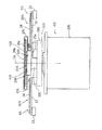
次に、図17ないし図25は、第6の実施形態に係る搬送ロボットを示している。 Next, FIGS. 17 to 25 show a transfer robot according to a sixth embodiment.
図17ないし図21に表れているように、この搬送ロボットA1は、概して、固定ベース200に対して鉛直状の旋回軸Osを中心として旋回可能な旋回ベース300と、この旋回ベース300に設けられた直進ガイド機構400と、この直進ガイド機構400に対して共通的に支持され、同一方向に移動可能に支持された第1移動部材20Aおよび第2移動部材20Bと、これら第1移動部材20Aおよび第2移動部材20Bをそれぞれ駆動するように上記旋回ベース300に設けられた第1駆動機構30Aおよび第2駆動機構30Bとを備えている。第1移動部材20Aおよび第2移動部材20Bには、それぞれワークWを載置保持しうるハンド21a,21bが設けられている。
As shown in FIG. 17 to FIG. 21, the transfer robot A <b> 1 is generally provided in a
図21に良く表れているように、固定ベース200は、底壁部201と円筒状側壁部202と天井壁203とを備えた、略円柱状の外形を有するハウジング200Aを備えており、天井壁203には、中心開口204が形成されている。この固定ベース200の内部には、昇降ベース210が昇降可能に支持されている。昇降ベース210は、上記中心開口204よりも小径の外径をもち、上下方向に所定の寸法を有する円筒部211と、この円筒部211の下端に形成された外向フランジ部212とを有している。上記ハウジング200Aの円筒状側壁部202の内壁には、上下方向の直線ガイドレール220が複数取付けられているとともに、昇降ベース210の外向フランジ部212に設けた複数のガイド部材221が上記直線ガイドレール220に対して上下方向スライド移動可能に支持されている。これにより、昇降ベース210は、固定ベース200に対し、上下方向(鉛直軸方向)に移動可能であり、このとき、この昇降ベース210の円筒部211の上部が上記ハウジング200Aの中心開口204から出没する。固定ベース200の天井壁203と昇降ベース210の外向フランジ部212との間には、この昇降ベース210の円筒部211を取り囲むようにして配置されたベローズ230の両端が連結されており、このベローズ230は、昇降ベース210の上下方向の移動にかかわらず、上記固定ベース200の天井壁203と昇降ベース210の外向フランジ部212との間を気密シールする。
As shown in FIG. 21, the fixed
固定ベース200の内部にはまた、上記ベローズ230の外側において、鉛直方向に配置されて回転するネジ軸241と、このネジ軸241に螺合され、かつ昇降ベース210の外向フランジ部212に貫通状に固定されたナット部材242とからなるボールネジ機構240が配置されている。ネジ軸241は、その下端に取付けたプーリ243に掛け回された無端ベルト244によってモータM1に連携されており、このモータM1の駆動により、正逆方向に回転させられる。このようにしてネジ軸241を回転することにより、昇降ベース210が昇降させられる。
Inside the fixed
上記昇降ベース210に対し、上記旋回ベース300が鉛直状の旋回軸Osを中心として旋回可能に支持される。図21に表れているように、旋回ベース300の下部には、円柱部301が形成されており、この円柱部301が上記昇降ベース210の円筒部211の内部にベアリング302を介して回転可能に支持されている。そうして、旋回ベース300の円柱部301の下端部には、プーリ303が一体的に形成されており、昇降ベース210の円筒部211の中間壁213に支持させたモータM2の出力軸に取り付けたプーリ304との間に無端ベルト305が掛け回されている。これにより、上記モータM2を駆動することにより、上記旋回ベース300が旋回軸Osを中心として旋回させられる。
The
昇降ベース210の円筒部211と旋回ベース300の円柱部301との間にはまた、上記ベアリング302より上位に位置するシール機構306が介装されている。このシール機構306より下位の空間は、上記ベローズ230の外周側の固定ベース200内空間と連通しており、これにより、このような連通空間は、外部に対して気密シールされた閉じた空間となる。なお、この旋回ベース300の円柱部301には、旋回軸Osに沿って上下方向に貫通する中心孔307が形成されており、この中心孔307には、上記第1駆動機構30Aと第2駆動機構30Bとに駆動力を伝達するための伝動軸251,252が挿通されているが、これについては後述する。
A
上記旋回ベース300は、上記のように昇降ベース210に回転可能に支持される円柱部301の上方に、一部中空となって左右方向に延出するウイング部310を介して上部桁部320を備えており、この上部桁部320には、上記直進ガイド機構400が支持されている。ウイング部310の中空部には、上記第1駆動機構30Aと第2駆動機構30Bに駆動力を伝達するための機構が内蔵されるが、これについては後述する。
The
上記直進ガイド機構400は、ガイド部材410と、このガイド部材410上に設けられた一対の第1ガイドレール421と、一対の第2ガイドレール422とを有する。上記ガイド部材410は、水平方向に延びる長手軸線(移動行程GL)を有する平面視長矩形状をしているとともに、図21に表れているように、底壁411と、この底壁411の両側縁部に形成された左右の起立壁412とを備えている。上記一対の第1ガイドレール421は、ガイド部材410の底壁411上に、上記移動行程GLを挟んでこれに平行に、相互に所定間隔を置いて配置されている。上記一対の第2ガイドレール422は、一対の第1ガイドレール421の外側において、上記移動行程GLを挟んでこれに平行に配置されている。上記第1ガイドレール421には、第1移動部材20Aがその下部に設けたスライダ22aを介して上記移動行程GLに沿って移動可能に支持され、上記第2ガイドレール422には、第2移動部材20Bがスライダ22bを介して上記移動行程GLに沿って移動可能に支持されている。なお、図21にも表れているように、直進ガイド機構400のガイド部材410の上面は、各ガイドレール421,422の上方を覆うカバー部材420によって覆われている。
The
第1移動部材20Aと第2移動部材20Bとは、図17、図18等に表れているように、ガイド部材410の幅方向に所定長さ延びる水平板状のハンド支持部20a,20bを備えているが、これらハンド支持部20a,20bは、図21に表れているように、すきまを介して上下に重なるように位置させられ、互いに干渉することなく上記移動行程GLに沿って移動可能である。
As shown in FIGS. 17 and 18, the first moving
第1移動部材20Aのハンド支持部20aは、その下部に形成された膨出部23a、およびこの膨出部23aの下面に左右一対設けた上記スライダ22aを介して直接的に上記一対の第1ガイドレール421に支持されている。こうして、直接的に第1ガイドレール421に支持される第1移動部材20Aは、安定的な支持状態を得ることができる。一方、第2移動部材20Bのハンド支持部20bは、図21に表れているように、その幅方向両端部から上記第1移動部材20Aのハンド支持部20aの両側部を迂回して延びる一対の支持アーム23b、およびこの支持アーム23bに設けた上記スライダ22bを介して上記一対の第2ガイドレール422に支持されている。これにより、第1移動部材20Aと第2移動部材20Bとは、全体としても、互いに干渉することなく上記移動行程GLに沿って移動可能であるとともに、第2移動部材20Bについては、そのハンド支持部20bが両持ち状に上記第2ガイドレール422に支持されるため、安定的な支持状態を得ることができる。なお、第1移動部材20Aは、上記ガイド部材410の底壁411に形成したスリット411aを貫通して延びる連結アーム24aを介して上記第1駆動機構30Aに連携され、第2移動部材20Bは、上記一対の支持アーム23bのうちの一方を介して第2駆動機構30Bに連携される。
The
図17ないし図19に示されているように、各ハンド支持部20a,20bには、ガイド部材410の長手方向に延びるホーク状のハンド21a,21bが一体的に形成されており、これらのハンド21a,21b上には、液晶表示パネルの製造用ガラス基板等の、比較的大型の薄板状ワークWが載置保持される。
As shown in FIGS. 17 to 19, hawk-
上記第1移動部材20Aおよび上記第2移動部材20Bをそれぞれ上記のようにガイド部材410の移動行程GLに沿って移動させるための第1駆動機構30Aおよび第2駆動機構30Bは、上記移動行程GLに対して対称に形成されており、この第6の実施形態では、以下に説明するように構成されている。
The
すなわち、これら第1駆動機構30Aおよび第2駆動機構30Bは、上記した旋回ベース300のウイング部310において、旋回軸Osに対して横方向に所定距離離間して位置する第1垂直軸O1を中心として回動駆動される第1リンクアーム31と、同じくウイング部310において、第1垂直軸O1を通って上記移動行程GLと平行な平行線上に位置する第2垂直軸O2(図18、図23)を中心として回動可能な副リンクアーム32と、これら第1リンクアーム31および副リンクアーム32が第3垂直軸O3および第4垂直軸O4を中心として相対回動可能に連結される中間リンク33とを備えた平行四辺形リンク機構3Aを備えている。第1垂直軸O1と第3垂直軸O3の軸間距離は、第2垂直軸O2と第4垂直軸O4の軸間距離と等しく、第1垂直軸O1と第2垂直軸O2の軸間距離は、第3垂直軸O3と第4垂直軸O4の軸間距離と等しい。
That is, the
図21および図23に表れているように、上記第1リンクアーム31は、その基端に設けた軸31axを上記ウイング部310に対してベアリング41を介して回転可能に支持することにより、上記第1垂直軸O1を中心として回動可能に支持されている。上記副リンクアーム32もまた、図23に表れているように、その基端に設けた軸32axを上記ウイング部310に対してベアリング42を介して回転可能に支持することにより、上記第2垂直軸O2を中心として回動可能に支持されている。図21および図22に表れているように、上記第1リンクアーム31の先端部は、これに設けた軸31bxを上記中間リンク33に対してベアリング43を介して回転可能に支持することにより、中間リンク33に対して上記第3垂直軸O3を中心として相対回動可能に連結されており、上記副リンクアーム32の先端部もまた、これに設けた軸32bxを上記中間リンク33に対してベアリング44を介して回転可能に支持することにより、中間リンク33に対して上記第4垂直軸O4を中心として相対回動可能に連結されている。
As shown in FIG. 21 and FIG. 23, the
したがって、第1リンクアーム31を回動駆動すると、平行四辺形リンク機構3Aは変形するが、中間リンク33の方向、すなわち、上記第3垂直軸O3と第4垂直軸O4を結ぶ直線の方向は、常に上記ガイド部材410の移動行程GLと平行になる。
Therefore, when the
次に、これら第1駆動機構30Aと第2駆動機構30Bは、上記平行四辺形リンク機構3Aの中間リンク33における、上記第3垂直軸O3と第4垂直軸O4を通る直線上に位置する第5垂直軸O5を中心として相対回動可能な第2リンクアーム34を備えている。図22に表れているように、この第2リンクアーム34は、その基部に設けた軸34axをベアリング45を介して中間リンク33に対して支持することにより、上記第5垂直軸O5を中心として相対回動可能となっている。さらに、中間リンク33には、図22に表れているように、上記第1リンクアーム31に固定され、かつ上記第3垂直軸O3上に中心をもつ第1ギア31aと、第2リンクアーム34に固定され、かつ上記第5垂直軸O5上に中心をもつ第2ギア34aとを備えている。これら第1ギア31aと第2ギア34aとは互いに噛み合わされており、かつ、同径のギアである。なお、図20、図21等に表れているように、第2リンクアーム34は、第1リンクアーム31に対し、上下方向に離間しており、これらが互いに干渉することはない。
Next, the
図21に表れているように、上記第2リンクアーム34の他端部は、各移動部材20A,20Bに対し、第6垂直軸O6を中心として相対回動可能に連結されている。具体的には、第1移動機構30Aについては、第2リンクアーム34の他端部は、上記連結アーム24aに形成した軸34axをベアリング45を介して相対回動可能に支持することにより、第1移動部材20Aに対し、第6垂直軸O6を中心として相対回動可能に連結されており、第2移動機構30Bについては、第2リンクアーム34の他端部は、上記支持アーム23bの一方に形成した軸34bxをベアリング46を介して相対回動可能に支持することにより、第2移動部材20Bに対し、第6垂直軸O6を中心として相対回動可能に連結されている。この第6垂直軸O6は、上記第1垂直軸O1と第2垂直軸O2とを通る、上記移動行程GLと平行な水平直線(平行線)上に位置し、かつ、第2リンクアーム34の長さ、すなわち、第5垂直軸O5と第6垂直軸O6の軸間距離は、第1リンクアーム31の長さ、すなわち、第1垂直軸O1と第3垂直軸O3の軸間距離と等しくなっている。
As shown in FIG. 21, the other end of the
第1駆動機構30Aおよび第2駆動機構30Bは、上記昇降ベース210内に配置されたモータM3,M4を駆動源として駆動される。図21を参照して前述したように、旋回ベース300の下部円柱部301に設けた鉛直方向の中心孔307には、それぞれ回転可能な第1の伝動軸251と第2の伝動軸252とが同軸状に支持されている。より具体的には、第2の伝動軸252は円筒状の軸とされ、上記中心孔307にベアリング253を介して回転可能に支持されているとともに、この第2の伝動軸252の内部に、上記第1の伝動軸251がベアリング254を介して回転可能に支持されている。第1の伝動軸251の下端は、昇降ベース210の中間壁213に支持させたモータM3の出力軸に連結されている。第2の伝動軸252の下端には、プーリ255が設けられており、上記昇降ベース210の中間壁213に支持させたモータM4の出力軸に取付けたプーリ256との間に無端ベルト257が掛け回されている。
The
前述したように、旋回ベース300のウイング部310には、第1リンクアーム31の基端の軸31axがベアリング41を介して回転可能に支持されているが、より詳細には、図23に表れているように、ベアリング41より上位には、シール機構330が介装されている。これにより、ウイング部310の中空部と外部とが気密シールされる。旋回ベース300の円柱部301には、上記したように、第1の伝動軸251および第2の伝動軸252を支持する中心孔307が形成されているため、ウイング部310の中空部が昇降ベース210の下部空間と連通することになるが、上記シール機構330、昇降ベース210と旋回ベース300との間に設けた上記シール機構306、および、上記ベローズ230が協働して、ウイング部310の中空部、昇降ベース210の内部、ないし、固定ベース200における上記ベローズ230より外周側の連通空間が、外部に対して気密シールされることになる。
As described above, the base end shaft 31ax of the
図21に表れているように、第1リンクアーム31の基端の軸部31axは、ウイング部310の中空部に支持させた減速機構340の出力側に連携されている一方、この減速機構340の入力側の軸にはプーリ341が設けられている。第1駆動機構30Aについては、上記第1の伝動軸251の上端に設けたプーリ251aと上記減速機構340の入力側のプーリ341との間に無端ベルト342が掛け回され、一方、第2駆動機構30Bについては、上記第2の伝動軸252の上端に設けたプーリ252aと上記減速機構340の入力側のプーリ341との間に無端ベルト343が掛け回される。これにより、モータM3を正逆方向に回転駆動することにより、第1駆動機構30Aにおける第1リンクアーム31が、第1垂直軸O1を中心として回動させられる一方、モータM4を正逆方向に回転駆動することにより、第2駆動機構30Bにおける第1リンクアーム31が、第1垂直軸O1を中心として回動させられる。
As shown in FIG. 21, the shaft portion 31ax at the base end of the
次に、上記構成を備える搬送ロボットA1の全体的な動作について、説明する。 Next, the overall operation of the transfer robot A1 having the above configuration will be described.
前述したように、第1駆動機構30Aおよび第2駆動機構30Bのそれぞれにおいて、第1リンクアーム31を第1垂直軸O1を中心として回動させると、上記平行四辺形リンク機構3Aが変形するが、中間リンク33の方向、すなわち、第3垂直軸O3と第4垂直軸O4を結ぶ直線は、常に上記ガイド部材410の移動行程GLと平行な関係を維持する(図24、図25参照)。一方、図22および図24に表れているように、中間リンク33において、第1リンクアーム31に固定された第1ギア31aと第2リンクアーム34に固定された第2ギア34aは、同じ径であって互いに噛み合っているので、第1リンクアーム31と中間リンク33とがなす角αと、第2リンクアーム34と中間リンク33とがなす角βとは、常に等しくなる(図24)。前述したように、第1リンクアーム31と第2リンクアーム34とは長さが等しいから、第1垂直軸O1と第6垂直軸O6を結ぶ直線は、常に中間リンク33、すなわち、第3垂直軸O3と第5垂直軸O5を結ぶ直線と平行となる。このことは、上記第1駆動機構30Aおよび第2駆動機構30Bが、対応する第1移動部材20Aおよび第2移動部材20Bを、ガイド部材410の移動行程GLに沿って移動させることができることを意味する。
As described above, in each of the
この実施形態では、上記したように、第1リンクアーム31と第2リンクアーム34とは、互いに上下方向に離間させられていて干渉することがないので、図24、図25に表れているように、第1リンクアーム31が第1垂直軸O1に対してガイド部材410の長手方向一端方向に回動している状態から、ガイド部材410の長手方向他端方向に回動している状態まで、不都合なく上記平行四辺形リンク機構3Aの変形が行なわれ、ガイド部材410の全長にわたって各移動部材20A,20Bを移動させることができる。そして、上記したように、第1駆動機構30Aおよび第2駆動機構30Bは、それ自体、対応する第1移動部材20Aおよび第2移動部材20Bを上記水平直線状の移動行程GLに沿って移動させることができるので、第1リンクアーム31と第2リンクアーム34とが重なる、いわゆる思案点付近においても(図17、図18の状態)、安定して各移動部材20A,20Bを移動させることができる。
In this embodiment, as described above, the
この搬送ロボットA1においてはまた、各移動部材20A,20Bの最終的な移動直進性は上記したように直進ガイド機構400によって達成される。また、各移動部材20A,20Bおよびこれに載置されるワークWの重量もまた、実質的に直進ガイド機構400によって支持される。したがって、上記第1駆動機構30Aおよび第2駆動機構30Bに求められる部材強度あるいは各部の精度が低くてよく、その結果、この搬送ロボットA1は、低コストで製作することができる。
Also in the transfer robot A1, the final moving straightness of each moving
さらに、上記構成の搬送ロボットA1は、第1駆動機構30Aおよび第2駆動機構30Bにより、第1移動部材20Aと第2移動部材20Bとを、平面視において同一の直線状移動行程(ガイド部材410の移動行程GL)に沿って各別に移動させることができるため、ワークWの搬送効率が著しく向上する。
Further, the transport robot A1 having the above configuration causes the
その結果、上記構成の搬送ロボットA1は、ワークWの大きさや重量に関わらず、正確な直進性をもってこのワークWを効率的に搬送することができ、しかも、コスト低減が可能である。 As a result, the transfer robot A1 configured as described above can efficiently transfer the workpiece W with accurate straightness regardless of the size and weight of the workpiece W, and the cost can be reduced.
なお、この実施形態に係る搬送ロボットA1は、旋回ベース300が支持される昇降ベース210が固定ベース200に対して昇降するように構成されているので、直進ガイド機構400の上下高さを適宜変更することができるし、また、旋回ベース300を旋回軸Osを中心として旋回させることにより、ガイド部材410の中心軸(移動行程GL)が所望の方向を向くように適宜直進ガイド機構400を旋回させることができる。また、直進ガイド機構400において、第1移動部材20Aのハンド支持部20aおよび第2移動部材20Bのハンド支持部20bは、互いに干渉することなくすきまを介して上下に離間しているが、昇降ベース210を昇降させることにより、第1移動部材20Aのハンド支持部20aと第2移動部材20Bのハンド支持部20bとの3次元的な移動行程を完全一致させることもできる。したがって、同一の搬送元からのワークWの受け取り、あるいは同一の搬送先へのワークWの受け渡しといった作業を、第1移動部材20Aと第2移動部材20Bのいずれを用いても行うことができるのであり、これにより、ワークWの搬送効率が著しく向上するのである。
The transfer robot A1 according to this embodiment is configured such that the elevating
また、上記構成の搬送ロボットA1は、上記したように、固定ベース200における上記ベローズ230の外周側の空間、昇降ベース210の内部、ないし、旋回ベース300のウイング部310の中空部にいたって連通する空間は、外部に対して気密シールされている。したがって、昇降ベース210を昇降させるためのモータM1ないし関連機構、旋回ベース300を旋回させるためのモータM2ないし関連機構、第1駆動機構30Aの第1リンクアーム31を回動させるためのモータM3ないし減速機構340を含めた関連機構、および、第2駆動機構30Bの第1リンクアーム31を回動させるためのモータM4ないし減速機構340を含めた関連機構として、真空対応のものではない安価な構成のものを採用しても、この搬送ロボットA1を真空雰囲気下に設置して、作動させることができる。
Further, as described above, the transfer robot A1 configured as described above communicates with the space on the outer peripheral side of the
次に、図26ないし図31は、第7の実施形態に係る搬送ロボットを示している。なお、この第7の実施形態については、特に第6の実施形態や第4の実施形態の要素と同一または類似の要素を同一符号で示し、その説明を適宜省略する。 Next, FIGS. 26 to 31 show a transfer robot according to a seventh embodiment. In the seventh embodiment, elements that are the same as or similar to those in the sixth embodiment and the fourth embodiment are designated by the same reference numerals, and description thereof is omitted as appropriate.
この第7の実施形態では、図26ないし図29に表れているように、第2移動部材20Bには、さらに別の補助移動部材2’が移動行程GLに沿って移動可能に支持されている。この補助移動部材2’は、ハンド21b’およびハンド支持部20b’を有しており、ハンド支持部20b’には、移動行程GLに対して交差する方向に長手状の案内溝20’が設けられている。このような第7の実施形態においては、第2移動部材20Bと第2駆動機構30B’の構成が上記第6の実施形態の構成と異なる。その他、第1リンクアーム31と副リンクアーム32との位置関係が逆である点等を除き、第1移動部材20Aや第1駆動機構30A等の構成については、上記第6の実施形態の構成と同様である。なお、第1リンクアーム31と副リンクアーム32との位置関係が第6の実施形態とは逆であるが、第6の実施形態等と同様の動作となる。
In the seventh embodiment, as shown in FIGS. 26 to 29, another
具体的には、図29によく表れているように、第2移動部材20Bは、その上部に一対のガイドレール23を有する。これらのガイドレール23は、第2移動部材20Bの上部において、上記移動行程GLを挟んでこれに平行に、相互に所定間隔を置いて配置されている。上記ガイドレール23には、補助移動部材2’がその下部に設けたスライダ22’を介して上記移動行程GLに沿って移動可能に支持されている。また、第2移動部材20Bは、その上部から両側を迂回して延びる一対の支持アーム23bを有しており、これら支持アーム23bの一方には、上向き突出状に軸34bxが形成されている(図27〜29参照)。このような第2移動部材20Bは、上記軸34bxを介して第2駆動機構30B’に連携されている。一方、補助移動部材2’は、上記案内溝20’の内部にガイドレール21’を備えている。このガイドレール21’には、第2リンクアーム34がその先端軸34cxのスライダ34cを介して移動可能に支持されている(図29参照)。つまり、補助移動部材2’も、上記先端軸34cxを介して第2駆動機構30B’に連携されている。
Specifically, as clearly shown in FIG. 29, the second moving
上記第2駆動機構30B’は、これに含まれる第1リンクアーム31、副リンクアーム32、および中間リンク33の構成が上記第6の実施形態の構成と同様であるものの、第2リンクアーム34の構成が若干異なる。第2リンクアーム34は、図29に表れているように、第1リンクアーム31に対し、上下方向に相当離間しており、これらが互いに干渉することはない。この第2リンクアーム34の先端部は、上記先端軸34cxをベアリング47を介して相対回動可能に支持することにより、補助移動部材2’に対し、第7垂直軸O7を中心として相対回動可能で、なおかつ上記案内溝20’に沿って変位可能に連結されている。このような第2リンクアーム34の長さ、すなわち、第5垂直軸O5と第7垂直軸O7の軸間距離は、第1リンクアーム31の長さ、すなわち、第1垂直軸O1と第3垂直軸O3の軸間距離より大きくなっている。ただし、第2リンクアーム34における第5垂直軸O5と第6垂直軸O6の軸間距離は、第1垂直軸O1と第3垂直軸O3の軸間距離と等しい。
The
また、上記第6の実施形態と同様に、上記第2駆動機構30B’の第1リンクアーム31には、第3垂直軸O3上に中心をもつ第1ギア31aが固定されており、第2駆動機構30B’の第2リンクアーム34には、第5垂直軸O5上に中心をもつ第2ギア34aが固定されている。これら第1ギア31aと第2ギア34aとは、同径であって互いに噛み合わされているため、第1リンクアーム31が第1垂直軸O1を中心として回動すると、それに伴い第2リンクアーム34が第5垂直軸O5を中心として所定の方向に回動する。
Similarly to the sixth embodiment, a
このような構成によれば、上記第6の実施形態によるものと同様の利点に加え、先述した第4の実施形態によるものと同様の利点を享受することができる。さらに優れた点としては、以下の点を挙げることができる。 According to such a configuration, in addition to the same advantages as those of the sixth embodiment, the same advantages as those of the above-described fourth embodiment can be enjoyed. Further excellent points include the following points.
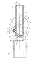
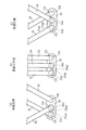
たとえば、図30および図31に示されているように、上記構成を備えた搬送ロボットは、トランスポートチャンバT内に配置されている。このトランスポートチャンバTは、開閉式のドアDを介してプロセスチャンバPに連通している。トランスポートチャンバT内の搬送ロボットは、ドアDを開とすることにより、プロセスチャンバPへのワークWの移送が可能となる。なお、図示の便宜上、図30には、第1移動部材20Aおよび第1移動機構30Aを示し、図31には、第2移動部材20Bおよび補助移動部材2’ならびに第2駆動機構30B’を示す。
For example, as shown in FIGS. 30 and 31, the transfer robot having the above-described configuration is disposed in the transport chamber T. The transport chamber T communicates with the process chamber P through an openable door D. The transfer robot in the transport chamber T can transfer the workpiece W to the process chamber P by opening the door D. For convenience of illustration, FIG. 30 shows the first moving
図30の(a)および(b)に示されているように、第1移動部材20Aおよび第1移動機構30Aを利用してトランスポートチャンバTからプロセスチャンバPへとワークWを移送する場合には、第6の実施形態で説明したように第1移動機構30Aが作動することにより、移動行程GLに沿って第1移動部材20Aが前進動する。このとき、図30の(b)に示されているように、第1移動部材20Aについては、ハンド21aとともにハンド支持部20aの一部もドアDを越えてプロセスチャンバP内に進入する。
As shown in FIGS. 30A and 30B, when the workpiece W is transferred from the transport chamber T to the process chamber P using the first moving
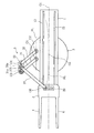
一方、図31の(a)および(b)に示されているように、第2移動部材20Bおよび補助移動部材2’ならびに第2駆動機構30B’を利用してトランスポートチャンバTからプロセスチャンバPへとワークWを移送する場合には、第4の実施形態で説明した移動機構のように第2駆動機構30B’が作動することにより、移動行程GLに沿って第2移動部材20Bおよび補助移動部材2’が連動しながら前進動する。このとき、図31の(b)に示されているように、第2移動部材20Bについては、支持アーム23bが移動行程GLの両側に張り出ており、この支持アーム23bがドアDの両側と干渉するため、ドアDの手前で止まる。その一方、補助移動部材2’については、ハンド支持部20b’がドアDの幅よりも小さいため、このハンド支持部20b’の一部もハンド21b’とともにドアDを越えてプロセスチャンバP内に進入する。したがって、上下2段式の移動部材20A,20Bを備えた構成でも、同じ位置までワークWを移送することができる。また、トランスポートチャンバTとプロセスチャンバPとの間には、できる限り幅の小さいドアDを設けることができ、ひいてはトランスポートチャンバTやプロセスチャンバPを小型化することができる。
On the other hand, as shown in FIGS. 31A and 31B, the process chamber P is transported from the transport chamber T using the second moving
次に、図32ないし図34は、第8の実施形態に係る搬送ロボットを示している。なお、この第8の実施形態については、特に第7の実施形態の要素と同一または類似の要素を同一符号で示し、その説明を適宜省略する。 Next, FIGS. 32 to 34 show a transfer robot according to an eighth embodiment. In the eighth embodiment, elements that are the same as or similar to those in the seventh embodiment are designated by the same reference numerals, and the description thereof is omitted as appropriate.
この第8の実施形態では、図32および図33に表れているように、第1移動部材20Aのハンド21aと補助移動部材2’のハンド21b’が重なる状態において、第1移動部材20Aと第2移動部材20Bとが上下に離間するすきまには、水平状のカバー7が設けられている。このカバー7は、図32によく示されているように、第1移動部材20Aのハンド21aと補助移動部材2’のハンド21b’が重なる領域から第1移動部材20Aと第2移動部材20Bが重なる領域まで占めており、ワークW全体を覆う面積をもっている。また、上記カバー7は、図33によく示されているように、第1移動部材20Aの両側部を迂回して延びる一対の支持アーム7a’を介して直進ガイド機構400に支持されている。つまり、カバー7の下方では、第1移動部材20Aが移動行程GLに沿って移動可能であり、カバー7の上方では、第2移動部材20Bおよび補助移動部材2’が移動行程GLに沿って移動可能である。
In the eighth embodiment, as shown in FIGS. 32 and 33, the first moving
このような構成によれば、次のような利点が得られる。 According to such a configuration, the following advantages can be obtained.
たとえば、図34の(a)および(b)に示されているように、第1移動部材20Aおよび第1移動機構30Aを利用してトランスポートチャンバTからプロセスチャンバPへとワークWを移送する場合には、第7の実施形態と同様に第1移動機構30Aを作動させることにより、移動行程GLに沿って第1移動部材20Aを前進動させることができる。また、図34の(c)に示されているように、第2移動部材20Bおよび補助移動部材2’ならびに第2駆動機構30B’を利用してトランスポートチャンバTからプロセスチャンバPへとワークWを移送する場合にも、第7の実施形態と同様に第2駆動機構30B’を作動させることにより、移動行程GLに沿って第2移動部材20Bおよび補助移動部材2’を前進動させることができる。ところで、第2移動部材20Bおよび補助移動部材2’が移動する際には、それに伴って第2移動部材20Bや補助移動部材2’、あるいは補助移動部材2’のハンド21b’に載せられたワークWから異物(パーティクル)が下方に落ちてくることがある。このような異物は、結局のところ、カバー7によって受け止められる。したがって、カバー7を備えた搬送ロボットによれば、特に第1移動部材20Aに載せられた状態で第2移動部材20Bよりも下方に位置するワークWに関し、搬送時に異物が付着するといったおそれがなく、できる限りきれいな状態でワークWを搬送することができる。なお、このようなカバーは、上記第6の実施形態に係る搬送ロボットに設けてもよい。
For example, as shown in FIGS. 34A and 34B, the workpiece W is transferred from the transport chamber T to the process chamber P using the first moving
なお、本願発明に係る搬送ロボットは、上記した各実施形態に限定されるものではない。 The transport robot according to the present invention is not limited to the above-described embodiments.
上記では、真空雰囲気下で用いることを前提として説明をしたが、もちろん、本願発明に係る搬送ロボットは、大気圧下で用いるものとして構成することも可能である。 Although the above description has been made on the premise that the robot is used in a vacuum atmosphere, of course, the transfer robot according to the present invention can be configured to be used under atmospheric pressure.
また、上記第1の実施形態等では、駆動機構(3,30A,30B,30B’)を作動させるためにギア列を備えているが、この種の駆動機構を作動させるための機構としては、たとえばプーリとベルトを用いて動力を伝える仕組みでもよい。 In the first embodiment and the like, a gear train is provided to operate the drive mechanism (3, 30A, 30B, 30B ′). As a mechanism for operating this type of drive mechanism, For example, a mechanism that transmits power using a pulley and a belt may be used.
特に上記第1および第6の実施形態の変形例としては、たとえば図35に示されている構成を備えた駆動機構でもよい。この変形例に係る駆動機構では、上記第1ギア(31a)に代え、第1リンクアーム31には、第3垂直軸O3上に中心をもつ第1間欠ギア31a’が固定されている。また、上記第2ギア(34a)に代え、第2リンクアーム34には、第5垂直軸O5上に中心をもつとともに上記第1間欠ギア31a’と一時的に噛み合う第2間欠ギア34a’が固定されている。第1間欠ギア31a’は、その周部一部に凹部31aa’を有する一方、第2間欠ギア34a’は、その周部一部に凸部34aa’を有する。これら第1間欠ギア31a’および第2間欠ギア34a’は、図35の(b)に示されているように、思案点付近において凹部31aa’と凸部34aa’とが互いに噛み合うように位置決めされた状態で、それぞれ第1リンクアーム31および第2リンクアーム34に固定されている。
In particular, as a modification of the first and sixth embodiments, for example, a drive mechanism having the configuration shown in FIG. 35 may be used. In the drive mechanism according to this modification, a first
このような変形例の構成によれば、図35の(a)および(c)に示されているように、移動部材(図示略)が思案点に対してある程度の前進位置や後退位置をとるときは、第1間欠ギア31a’の凹部31aa’と第2間欠ギア34a’の凸部34aa’とが噛み合わない。このような状態でも第1リンクアーム31が第1垂直軸(図示略)を中心として所定方向に回動する状況においては、第2リンクアーム34と移動部材との連結点(図示略した第6垂直軸)が移動行程(図示略)と常に一致あるいは常に平行するように設定されているため、第2リンクアーム34が第5垂直軸O5を中心として所定方向に回動し、それに伴い移動部材が移動行程に沿って移動する。一方、図35の(b)に示されているように、移動部材が思案点付近にあるときには、第1間欠ギア31a’の凹部31aa’と第2間欠ギア34a’の凸部34aa’とが確実に噛み合う。これにより、思案点付近で第1リンクアーム31が第1垂直軸O1を中心として所定方向に回動すると、それに連動して第2リンクアーム34が第5垂直軸O5を中心として所定方向に回動し、それに伴い移動部材が移動行程に沿って移動する。したがって、図35に示される変形例の駆動機構によっても、移動部材を移動行程上の最前進位置から思案点を経て最後退位置まで、あるいはその逆方向に滞りなくスムーズに移動させることができる。
According to the configuration of such a modification, as shown in FIGS. 35A and 35C, the moving member (not shown) takes a certain forward or backward position with respect to the thought point. At this time, the concave portion 31aa ′ of the first
特に図示しないが、上記第5の実施形態に関しても、上記と同様の間欠ギアを備えた構成を変形例として採用してもよい。その場合、第1リンクアーム(31)には、第3垂直軸(O3)上に中心をもつ第1間欠ギア(31a’)に加え、第8垂直軸(O8)上に中心をもつ第3間欠ギアが固定される。また、第2リンクアーム(34)には、第5垂直軸(O5)上に中心をもつとともに上記第1間欠ギア(31a’)と一時的に噛み合う第2間欠ギア(34a’)が固定される。さらに、第3リンクアーム(35)には、第10垂直軸(O10)上に中心をもつとともに上記第3間欠ギアと一時的に噛み合う第4間欠ギアが固定される。互いに噛み合う間欠ギアの関係については、先述した点と同様である。このような構成によっても、上記した第1および第6の実施形態の変形例によるものと同様の動作が実現されるとともに、同様の効果を得ることができる。 Although not particularly illustrated, the configuration including the intermittent gear similar to the above may be adopted as a modified example also for the fifth embodiment. In this case, the first link arm (31) includes a third intermittent gear (31a ′) centered on the third vertical axis (O3) and a third center centered on the eighth vertical axis (O8). Intermittent gear is fixed. A second intermittent gear (34a ′) having a center on the fifth vertical axis (O5) and temporarily meshing with the first intermittent gear (31a ′) is fixed to the second link arm (34). The Furthermore, a fourth intermittent gear having a center on the tenth vertical axis (O10) and temporarily meshing with the third intermittent gear is fixed to the third link arm (35). The relationship between the intermittent gears meshing with each other is the same as described above. Even with such a configuration, the same operation as that of the modification of the first and sixth embodiments described above can be realized, and the same effect can be obtained.
1,410 ガイド部材
2 移動部材
2’ 補助移動部材
20A 第1移動部材
20B 第2移動部材
20,20’ 案内溝
20a,20b,20b’ ハンド支持部
21a,21b,21b’ ハンド
23b 支持アーム
24a 連結アーム
3 駆動機構
3A 平行四辺形リンク機構
30A 第1駆動機構
30B,30B’ 第2駆動機構
31 第1リンクアーム
31a 第1ギア
31a’ 第1間欠ギア
31aa 第3ギア
32 副リンクアーム
33 中間リンク
33’ 補助中間リンク
34 第2リンクアーム
34a 第2ギア
34a’ 第2間欠ギア
35 第3リンクアーム
35a 第4ギア
300 旋回ベース
4,4’ ハンド
421 第1ガイドレール
422 第2ガイドレール
5,200 固定ベース
O1〜O11 第1〜第11垂直軸
Os 旋回軸
A,A1 搬送ロボット
B 直線移動機構
GL 移動行程
PL 平行線
AL 弧線
W ワーク
1,410
31aa
Claims (17)
上記駆動機構は、上記ガイド部材における上記移動行程上またはその平行線上の第1垂直軸を中心として回動駆動される第1リンクアームと、上記移動行程上またはその平行線上の上記第1垂直軸と異なる第2垂直軸を中心として回動可能な副リンクアームと、上記第1リンクアームおよび副リンクアームが第3垂直軸および第4垂直軸を中心として相対回動可能に連結される中間リンクとを備えた平行四辺形リンク機構を含むとともに、上記中間リンクに対して上記第3垂直軸と第4垂直軸を通る直線上の第5垂直軸を中心として相対回動可能に一端が連結されるとともに、他端が上記移動部材に対して上記移動行程と交差する方向に移動可能とされた第6垂直軸を中心として回動可能に連結された第2リンクアームを含んでおり、
上記第5垂直軸と上記第6垂直軸との軸間距離は、上記第1垂直軸と上記第3垂直軸との軸間距離と等しく設定されており、かつ、
上記第1リンクアームと上記第2リンクアームとは、上記第1リンクアームが回動駆動されるとき、上記第2リンクアームと上記移動部材との連結部の軌跡が、上記水平直線状の移動行程と一致もしくは平行するように連携されていることを特徴とする、直線移動機構。 A guide member, a movable member supported by the guide member so as to be slidable and movable along a horizontal linear movement stroke set on the guide member, and a drive mechanism for driving the movable member are provided. A linear movement mechanism,
The drive mechanism includes a first link arm that is rotationally driven around the first vertical axis on the movement stroke or the parallel line of the guide member, and the first vertical axis on the movement stroke or the parallel line. A sub-link arm rotatable about a second vertical axis different from the above, and an intermediate link in which the first link arm and the sub-link arm are connected so as to be relatively rotatable about a third vertical axis and a fourth vertical axis And having one end coupled to the intermediate link so as to be relatively rotatable about a fifth vertical axis on a straight line passing through the third vertical axis and the fourth vertical axis. And the other end includes a second link arm connected to be rotatable about a sixth vertical axis that is movable in a direction intersecting the moving stroke with respect to the moving member,
The inter-axis distance between the fifth vertical axis and the sixth vertical axis is set equal to the inter-axis distance between the first vertical axis and the third vertical axis, and
The first link arm and the second link arm are configured such that when the first link arm is rotationally driven, the locus of the connecting portion between the second link arm and the moving member moves in the horizontal linear movement. characterized in that it is cooperation to match or parallel to the stroke, the linear movement mechanism.
上記駆動機構は、上記ガイド部材における上記移動行程上またはその平行線上の第1垂直軸を中心として回動駆動される第1リンクアームと、上記移動行程上またはその平行線上の上記第1垂直軸と異なる第2垂直軸を中心として回動可能な副リンクアームと、上記第1リンクアームおよび副リンクアームが第3垂直軸および第4垂直軸を中心として相対回動可能に連結される中間リンクとを備えた平行四辺形リンク機構を含むとともに、上記中間リンクに対して上記第3垂直軸と第4垂直軸を通る直線上の第5垂直軸を中心として相対回動可能に一端が連結されるとともに、他端が上記移動部材に対して第6垂直軸を中心として回動可能に連結された第2リンクアームを含んでおり、
上記第5垂直軸と上記第6垂直軸との軸間距離は、上記第1垂直軸と上記第3垂直軸との軸間距離と等しく設定されており、
上記移動部材には、さらに別の補助移動部材が上記移動行程に沿って移動可能に支持されており、上記第2リンクアームは、上記補助移動部材に対し、上記第5垂直軸から第6垂直軸を通ってさらに延びる延長線上の第7垂直軸を中心として相対回動可能で、なおかつ上記第7垂直軸が上記移動行程と交差する方向に変位可能に連結されており、かつ、
上記第1リンクアームと上記第2リンクアームとは、上記第1リンクアームが回動駆動されるとき、上記補助移動部材に対する上記第2リンクアームの回動軸となる上記第7垂直軸の軌跡が、上記移動行程に沿って弧線を描くように連携されていることを特徴とする、直線移動機構。 A guide member, a movable member supported by the guide member so as to be slidable and movable along a horizontal linear movement stroke set on the guide member, and a drive mechanism for driving the movable member are provided. A linear movement mechanism,
The drive mechanism includes a first link arm that is rotationally driven around the first vertical axis on the movement stroke or the parallel line of the guide member, and the first vertical axis on the movement stroke or the parallel line. A sub-link arm rotatable about a second vertical axis different from the above, and an intermediate link in which the first link arm and the sub-link arm are connected so as to be relatively rotatable about a third vertical axis and a fourth vertical axis And having one end coupled to the intermediate link so as to be relatively rotatable about a fifth vertical axis on a straight line passing through the third vertical axis and the fourth vertical axis. And a second link arm whose other end is connected to the moving member so as to be rotatable about a sixth vertical axis.
The inter-axis distance between the fifth vertical axis and the sixth vertical axis is set equal to the inter-axis distance between the first vertical axis and the third vertical axis,
Further, another auxiliary moving member is supported on the moving member so as to be movable along the moving stroke, and the second link arm moves from the fifth vertical axis to the sixth vertical axis with respect to the auxiliary moving member. The seventh vertical axis is connected to be displaceable in a direction intersecting the moving stroke, and is rotatable relative to a seventh vertical axis on an extension line further extending through the axis; and
The first link arm and the second link arm are traces of the seventh vertical axis, which is a rotation axis of the second link arm with respect to the auxiliary moving member when the first link arm is driven to rotate. Are coordinated so as to draw an arc line along the moving stroke .
上記駆動機構は、上記ガイド部材における上記移動行程上またはその平行線上の第1垂直軸を中心として回動駆動される第1リンクアームと、上記移動行程上またはその平行線上の上記第1垂直軸と異なる第2垂直軸を中心として回動可能な副リンクアームと、上記第1リンクアームおよび副リンクアームが第3垂直軸および第4垂直軸を中心として相対回動可能に連結される中間リンクとを備えた平行四辺形リンク機構を含むとともに、上記中間リンクに対して上記第3垂直軸と第4垂直軸を通る直線上の第5垂直軸を中心として相対回動可能に一端が連結されるとともに、他端が上記移動部材に対して第6垂直軸を中心として回動可能に連結された第2リンクアームを含んでおり、
上記第5垂直軸と上記第6垂直軸との軸間距離は、上記第1垂直軸と上記第3垂直軸との軸間距離と等しく設定されており、
上記移動部材には、さらに別の補助移動部材が上記移動行程に沿って移動可能に支持されているとともに、上記平行四辺形リンク機構には、上記中間リンクより外側において、上記第1リンクアームおよび副リンクアームに第8垂直軸および第9垂直軸を中心として相対回動可能に連結された補助中間リンクが含まれており、この補助中間リンクには、上記第8垂直軸と第9垂直軸を通る直線上の第10垂直軸を中心として相対回動可能な第3リンクアームが連結されており、この第3リンクアームは、上記補助移動部材に対し、第11垂直軸を中心として相対回動可能に連結されており、かつ、上記第10垂直軸と上記第11垂直軸との軸間距離は、上記第1垂直軸と上記第8垂直軸との軸間距離と等しく設定されており、かつ、
上記第1リンクアームと上記第2リンクアームとは、上記第1リンクアームが回動駆動されるとき、上記第2リンクアームと上記移動部材との連結部の軌跡が、上記水平直線状の移動行程と一致もしくは平行するように連携されているとともに、上記第1リンクアームと上記第3リンクアームとは、上記第1リンクアームが回動するとき、上記補助移動部材に対する上記第3リンクアームの回動軸となる上記第11垂直軸の軌跡が、上記水平直線状の移動行程と一致もしくは平行するように連携されていることを特徴とする、直線移動機構。 A guide member, a movable member supported by the guide member so as to be slidable and movable along a horizontal linear movement stroke set on the guide member, and a drive mechanism for driving the movable member are provided. A linear movement mechanism,
The drive mechanism includes a first link arm that is rotationally driven around the first vertical axis on the movement stroke or the parallel line of the guide member, and the first vertical axis on the movement stroke or the parallel line. A sub-link arm rotatable about a second vertical axis different from the above, and an intermediate link in which the first link arm and the sub-link arm are connected so as to be relatively rotatable about a third vertical axis and a fourth vertical axis And having one end coupled to the intermediate link so as to be relatively rotatable about a fifth vertical axis on a straight line passing through the third vertical axis and the fourth vertical axis. And a second link arm whose other end is connected to the moving member so as to be rotatable about a sixth vertical axis.
The inter-axis distance between the fifth vertical axis and the sixth vertical axis is set equal to the inter-axis distance between the first vertical axis and the third vertical axis,
Further, another auxiliary moving member is supported by the moving member so as to be movable along the moving stroke, and the parallelogram link mechanism includes the first link arm and the outer side of the intermediate link. An auxiliary intermediate link connected to the sub link arm so as to be relatively rotatable about the eighth vertical axis and the ninth vertical axis is included. The auxiliary intermediate link includes the eighth vertical axis and the ninth vertical axis. Is connected to a third link arm that is relatively rotatable about a tenth vertical axis on a straight line passing through the first link axis, and the third link arm rotates relative to the auxiliary moving member about the eleventh vertical axis. The distance between the tenth vertical axis and the eleventh vertical axis is set to be equal to the distance between the first vertical axis and the eighth vertical axis. ,And,
The first link arm and the second link arm are configured such that when the first link arm is rotationally driven, the locus of the connecting portion between the second link arm and the moving member moves in the horizontal linear movement. The first link arm and the third link arm are coordinated so as to coincide with or parallel to the stroke, and the third link arm and the third link arm move when the first link arm rotates. A linear movement mechanism , wherein the trajectory of the eleventh vertical axis serving as a rotation axis is linked so as to coincide with or parallel to the horizontal linear movement stroke .
上記駆動機構は、上記ガイド部材における上記移動行程上またはその平行線上の第1垂直軸を中心として回動駆動される第1リンクアームと、上記移動行程上またはその平行線上の上記第1垂直軸と異なる第2垂直軸を中心として回動可能な副リンクアームと、上記第1リンクアームおよび副リンクアームが第3垂直軸および第4垂直軸を中心として相対回動可能に連結される中間リンクとを備えた平行四辺形リンク機構を含むとともに、上記中間リンクに対して上記第3垂直軸と第4垂直軸を通る直線上の第5垂直軸を中心として相対回動可能に一端が連結されるとともに、他端が上記移動部材に対して上記移動行程と交差する方向に移動可能とされた第6垂直軸を中心として回動可能に連結された第2リンクアームを含んでおり、
上記第5垂直軸と上記第6垂直軸との軸間距離は、上記第1垂直軸と上記第3垂直軸との軸間距離より大きく設定されており、かつ、
上記第1リンクアームと上記第2リンクアームとは、上記第1リンクアームが回動駆動されるとき、上記第2リンクアームと上記移動部材との連結部の軌跡が、上記水平直線状の移動行程に沿って弧線を描くように連携されていることを特徴とする、直線移動機構。 A guide member, a movable member supported by the guide member so as to be slidable and movable along a horizontal linear movement stroke set on the guide member, and a drive mechanism for driving the movable member are provided. A linear movement mechanism,
The drive mechanism includes a first link arm that is rotationally driven around the first vertical axis on the movement stroke or the parallel line of the guide member, and the first vertical axis on the movement stroke or the parallel line. A sub-link arm rotatable about a second vertical axis different from the above, and an intermediate link in which the first link arm and the sub-link arm are connected so as to be relatively rotatable about a third vertical axis and a fourth vertical axis And having one end coupled to the intermediate link so as to be relatively rotatable about a fifth vertical axis on a straight line passing through the third vertical axis and the fourth vertical axis. And the other end includes a second link arm connected to be rotatable about a sixth vertical axis that is movable in a direction intersecting the moving stroke with respect to the moving member,
The inter-axis distance between the fifth vertical axis and the sixth vertical axis is set to be greater than the inter-axis distance between the first vertical axis and the third vertical axis, and
The first link arm and the second link arm are configured such that when the first link arm is rotationally driven, the locus of the connecting portion between the second link arm and the moving member moves in the horizontal linear movement. A linear movement mechanism characterized by being linked so as to draw an arc line along a stroke .
Priority Applications (2)
| Application Number | Priority Date | Filing Date | Title |
|---|---|---|---|
| JP2004052902A JP4291709B2 (en) | 2003-04-16 | 2004-02-27 | Linear movement mechanism and transfer robot using the same |
| US10/825,267 US7306423B2 (en) | 2003-04-16 | 2004-04-14 | Linear moving mechanism and transfer robot using the same |
Applications Claiming Priority (3)
| Application Number | Priority Date | Filing Date | Title |
|---|---|---|---|
| JP2003111967 | 2003-04-16 | ||
| JP2003341137 | 2003-09-30 | ||
| JP2004052902A JP4291709B2 (en) | 2003-04-16 | 2004-02-27 | Linear movement mechanism and transfer robot using the same |
Publications (3)
| Publication Number | Publication Date |
|---|---|
| JP2005125479A JP2005125479A (en) | 2005-05-19 |
| JP2005125479A5 JP2005125479A5 (en) | 2007-03-08 |
| JP4291709B2 true JP4291709B2 (en) | 2009-07-08 |
Family
ID=34139360
Family Applications (1)
| Application Number | Title | Priority Date | Filing Date |
|---|---|---|---|
| JP2004052902A Expired - Fee Related JP4291709B2 (en) | 2003-04-16 | 2004-02-27 | Linear movement mechanism and transfer robot using the same |
Country Status (2)
| Country | Link |
|---|---|
| US (1) | US7306423B2 (en) |
| JP (1) | JP4291709B2 (en) |
Cited By (2)
| Publication number | Priority date | Publication date | Assignee | Title |
|---|---|---|---|---|
| JP7427351B2 (en) | 2017-12-05 | 2024-02-05 | 日本製鉄株式会社 | stacked iron core |
| JP7510213B2 (en) | 2022-05-31 | 2024-07-03 | 智▲ウェイ▼資訊科技股▲ふん▼有限公司 | Simulation equipment and operation system |
Families Citing this family (53)
| Publication number | Priority date | Publication date | Assignee | Title |
|---|---|---|---|---|
| JP4490341B2 (en) * | 2005-07-05 | 2010-06-23 | 株式会社ダイヘン | Link device and transfer robot |
| JP4440178B2 (en) * | 2005-07-25 | 2010-03-24 | 東京エレクトロン株式会社 | Substrate transfer device |
| JP4666215B2 (en) | 2005-08-10 | 2011-04-06 | 株式会社ダイフク | Article conveying device |
| JP4697791B2 (en) * | 2005-11-07 | 2011-06-08 | 株式会社アルバック | Substrate transfer device |
| JP2007250196A (en) | 2006-03-13 | 2007-09-27 | Ricoh Co Ltd | Carrier device and vacuum processing device |
| DE102006038505A1 (en) * | 2006-08-16 | 2008-02-21 | Kmb Produktions Ag | Device for moving objects |
| JP5041207B2 (en) * | 2006-11-14 | 2012-10-03 | 株式会社ダイフク | Goods transport equipment |
| JPWO2008120294A1 (en) | 2007-03-02 | 2010-07-15 | 株式会社ダイヘン | Transport device |
| JP5171093B2 (en) * | 2007-04-05 | 2013-03-27 | 株式会社アルバック | Transport device |
| JP5075459B2 (en) * | 2007-04-17 | 2012-11-21 | 株式会社アルバック | Transport device |
| DE112008000908T5 (en) * | 2007-04-05 | 2010-07-01 | ULVAC, Inc., Chigasaki-shi | transport device |
| JP4950745B2 (en) | 2007-04-19 | 2012-06-13 | 株式会社ダイヘン | Transport device |
| JP4908306B2 (en) * | 2007-05-10 | 2012-04-04 | 株式会社ダイヘン | Transport device |
| WO2008140093A1 (en) * | 2007-05-15 | 2008-11-20 | Ulvac, Inc. | Transfer apparatus, and vacuum treating apparatus |
| JP4971063B2 (en) | 2007-07-27 | 2012-07-11 | 株式会社ダイヘン | Transport device |
| JP4824645B2 (en) * | 2007-08-03 | 2011-11-30 | 株式会社アルバック | Substrate transfer device |
| JP4918430B2 (en) * | 2007-08-03 | 2012-04-18 | 株式会社アルバック | Substrate transfer device |
| JP4824648B2 (en) * | 2007-08-07 | 2011-11-30 | 株式会社アルバック | Substrate transfer device |
| DE102007039398B4 (en) * | 2007-08-21 | 2009-11-12 | Saadat, Mohammad Mohsen, Prof. Dr.-Ing. | Gripping mechanism for robots, machines and handling devices |
| CN101417747B (en) * | 2008-12-11 | 2011-11-23 | 友达光电股份有限公司 | Conveyer table mechanism |
| US8285418B2 (en) * | 2009-07-23 | 2012-10-09 | Kla-Tencor Corporation | Dual scanning stage |
| JP5419581B2 (en) * | 2009-07-31 | 2014-02-19 | 東京エレクトロン株式会社 | Method for assembling transfer mechanism and transfer chamber |
| USD639323S1 (en) * | 2010-05-06 | 2011-06-07 | Ulvac, Inc. | Vacuum transfer robot |
| USRE44567E1 (en) * | 2009-11-17 | 2013-11-05 | Ulvac, Inc. | Vacuum transfer robot |
| USD625748S1 (en) * | 2010-05-06 | 2010-10-19 | Ulvac, Inc. | Vacuum transfer robot |
| USRE43781E1 (en) * | 2009-11-17 | 2012-11-06 | Ulvac, Inc. | Vacuum transfer robot |
| CN102092045B (en) * | 2009-12-15 | 2012-09-05 | 北京北方微电子基地设备工艺研究中心有限责任公司 | Substrate processing system and mechanical arm device thereof |
| TWI395633B (en) * | 2010-04-23 | 2013-05-11 | 私立中原大學 | Toggle-type positioning platform |
| GB2486486A (en) * | 2010-12-17 | 2012-06-20 | Uhv Design Ltd | Work piece transfer mechanism with a linear stroke |
| CN102530556B (en) * | 2010-12-20 | 2015-06-24 | 理想能源设备(上海)有限公司 | Substrate conveying device, method and system |
| EP2469339B1 (en) | 2010-12-21 | 2017-08-30 | ASML Netherlands B.V. | Lithographic apparatus and device manufacturing method |
| JP2012218144A (en) * | 2011-04-11 | 2012-11-12 | Komiyama Electron Co Ltd | Conveyance system |
| CN202072285U (en) * | 2011-05-24 | 2011-12-14 | 深圳市华星光电技术有限公司 | Panel conveying device and panel supporting mechanism thereof |
| CN104271447B (en) * | 2011-10-24 | 2016-05-04 | 莱米迪科技控股有限责任公司 | For packaging system and the correlation technique of medicament dispenser |
| JP5663638B2 (en) | 2012-10-11 | 2015-02-04 | 株式会社ティーイーエス | Substrate transfer device |
| CN103811385B (en) * | 2012-11-08 | 2016-06-29 | 沈阳新松机器人自动化股份有限公司 | A kind of manipulator mechanism for transporting wafer |
| US9149936B2 (en) | 2013-01-18 | 2015-10-06 | Persimmon Technologies, Corp. | Robot having arm with unequal link lengths |
| US10224232B2 (en) | 2013-01-18 | 2019-03-05 | Persimmon Technologies Corporation | Robot having two arms with unequal link lengths |
| JP6063776B2 (en) * | 2013-03-04 | 2017-01-18 | 東京エレクトロン株式会社 | Substrate transport path determination method, substrate transport apparatus, substrate processing apparatus, and program |
| KR101515908B1 (en) | 2013-07-29 | 2015-04-29 | 주식회사 티이에스 | Apparatus for transferring substrate |
| JP6863744B2 (en) * | 2014-01-17 | 2021-04-21 | ブルックス オートメーション インコーポレイテッド | Transport equipment and processing equipment |
| JP6276090B2 (en) | 2014-03-31 | 2018-02-07 | 株式会社ダイヘン | Transport device, transport system |
| JP6474971B2 (en) * | 2014-07-03 | 2019-02-27 | 株式会社ダイヘン | Work transfer device |
| US11691268B2 (en) | 2015-03-12 | 2023-07-04 | Persimmon Technologies Corporation | Robot having a variable transmission ratio |
| US10470841B2 (en) | 2017-03-28 | 2019-11-12 | Steris Inc. | Robot-based rack processing system |
| JP1612766S (en) * | 2018-03-29 | 2018-09-03 | ||
| JP1612912S (en) * | 2018-03-29 | 2018-09-03 | ||
| JP1612908S (en) * | 2018-03-29 | 2018-09-03 | ||
| JP1619125S (en) * | 2018-03-29 | 2018-11-26 | ||
| USD892881S1 (en) * | 2018-03-29 | 2020-08-11 | Daihen Corporation | Power transmission unit and power receiving unit of an industrial robot arm |
| TWI758595B (en) * | 2018-03-31 | 2022-03-21 | 日商平田機工股份有限公司 | chamber configuration |
| CN110960807B (en) * | 2019-12-05 | 2022-03-04 | 上海联影医疗科技股份有限公司 | Medical linear accelerator system |
| JP2022104004A (en) * | 2020-12-28 | 2022-07-08 | 日本電産サンキョー株式会社 | Industrial robot |
Family Cites Families (3)
| Publication number | Priority date | Publication date | Assignee | Title |
|---|---|---|---|---|
| JP2808826B2 (en) * | 1990-05-25 | 1998-10-08 | 松下電器産業株式会社 | Substrate transfer device |
| JPH106258A (en) | 1996-06-19 | 1998-01-13 | Metsukusu:Kk | Thin form work conveying robot |
| US6910847B1 (en) * | 2002-07-19 | 2005-06-28 | Nanometrics Incorporated | Precision polar coordinate stage |
-
2004
- 2004-02-27 JP JP2004052902A patent/JP4291709B2/en not_active Expired - Fee Related
- 2004-04-14 US US10/825,267 patent/US7306423B2/en not_active Expired - Lifetime
Cited By (2)
| Publication number | Priority date | Publication date | Assignee | Title |
|---|---|---|---|---|
| JP7427351B2 (en) | 2017-12-05 | 2024-02-05 | 日本製鉄株式会社 | stacked iron core |
| JP7510213B2 (en) | 2022-05-31 | 2024-07-03 | 智▲ウェイ▼資訊科技股▲ふん▼有限公司 | Simulation equipment and operation system |
Also Published As
| Publication number | Publication date |
|---|---|
| US20050036877A1 (en) | 2005-02-17 |
| JP2005125479A (en) | 2005-05-19 |
| US7306423B2 (en) | 2007-12-11 |
Similar Documents
| Publication | Publication Date | Title |
|---|---|---|
| JP4291709B2 (en) | Linear movement mechanism and transfer robot using the same | |
| JP4950745B2 (en) | Transport device | |
| JP4971063B2 (en) | Transport device | |
| EP1498228B1 (en) | Articulated robot | |
| JP4955447B2 (en) | Transport device | |
| JP2011199121A (en) | Conveying apparatus | |
| KR101512912B1 (en) | Conveyance robot | |
| TWI508213B (en) | A carrying arm and a handling robot having the carrying arm | |
| US20080023293A1 (en) | Linear transfer mechanism and transfer robot using the same | |
| JP4369851B2 (en) | Linear movement mechanism and transfer robot using the same | |
| US7946799B2 (en) | Transfer apparatus | |
| JP2013000839A (en) | Transfer robot | |
| TWI581929B (en) | Substrate transfer robot and its operation method | |
| WO2016189565A1 (en) | Horizontal articulated robot | |
| JP4276534B2 (en) | Transfer robot | |
| JP4515133B2 (en) | Conveying apparatus, control method therefor, and vacuum processing apparatus | |
| JP2019029670A (en) | Transfer apparatus | |
| KR101193761B1 (en) | Articulated robot | |
| JP2005186259A5 (en) | ||
| JP6557475B2 (en) | Industrial robot | |
| US7018162B2 (en) | Articulated carrying device | |
| JP5668678B2 (en) | robot | |
| JP5255683B2 (en) | Transport device | |
| JP4879833B2 (en) | Transport device | |
| JP2003094359A (en) | Link type work conveying robot |
Legal Events
| Date | Code | Title | Description |
|---|---|---|---|
| A521 | Request for written amendment filed |
Free format text: JAPANESE INTERMEDIATE CODE: A523 Effective date: 20070122 |
|
| A621 | Written request for application examination |
Free format text: JAPANESE INTERMEDIATE CODE: A621 Effective date: 20070122 |
|
| A977 | Report on retrieval |
Free format text: JAPANESE INTERMEDIATE CODE: A971007 Effective date: 20080619 |
|
| A131 | Notification of reasons for refusal |
Free format text: JAPANESE INTERMEDIATE CODE: A131 Effective date: 20080715 |
|
| A521 | Request for written amendment filed |
Free format text: JAPANESE INTERMEDIATE CODE: A523 Effective date: 20080916 |
|
| A131 | Notification of reasons for refusal |
Free format text: JAPANESE INTERMEDIATE CODE: A131 Effective date: 20081216 |
|
| A521 | Request for written amendment filed |
Free format text: JAPANESE INTERMEDIATE CODE: A523 Effective date: 20090216 |
|
| TRDD | Decision of grant or rejection written | ||
| A01 | Written decision to grant a patent or to grant a registration (utility model) |
Free format text: JAPANESE INTERMEDIATE CODE: A01 Effective date: 20090331 |
|
| A01 | Written decision to grant a patent or to grant a registration (utility model) |
Free format text: JAPANESE INTERMEDIATE CODE: A01 |
|
| A61 | First payment of annual fees (during grant procedure) |
Free format text: JAPANESE INTERMEDIATE CODE: A61 Effective date: 20090403 |
|
| R150 | Certificate of patent or registration of utility model |
Ref document number: 4291709 Country of ref document: JP Free format text: JAPANESE INTERMEDIATE CODE: R150 Free format text: JAPANESE INTERMEDIATE CODE: R150 |
|
| FPAY | Renewal fee payment (event date is renewal date of database) |
Free format text: PAYMENT UNTIL: 20120410 Year of fee payment: 3 |
|
| FPAY | Renewal fee payment (event date is renewal date of database) |
Free format text: PAYMENT UNTIL: 20120410 Year of fee payment: 3 |
|
| FPAY | Renewal fee payment (event date is renewal date of database) |
Free format text: PAYMENT UNTIL: 20130410 Year of fee payment: 4 |
|
| FPAY | Renewal fee payment (event date is renewal date of database) |
Free format text: PAYMENT UNTIL: 20130410 Year of fee payment: 4 |
|
| FPAY | Renewal fee payment (event date is renewal date of database) |
Free format text: PAYMENT UNTIL: 20140410 Year of fee payment: 5 |
|
| R250 | Receipt of annual fees |
Free format text: JAPANESE INTERMEDIATE CODE: R250 |
|
| R250 | Receipt of annual fees |
Free format text: JAPANESE INTERMEDIATE CODE: R250 |
|
| R250 | Receipt of annual fees |
Free format text: JAPANESE INTERMEDIATE CODE: R250 |
|
| R250 | Receipt of annual fees |
Free format text: JAPANESE INTERMEDIATE CODE: R250 |
|
| R250 | Receipt of annual fees |
Free format text: JAPANESE INTERMEDIATE CODE: R250 |
|
| R250 | Receipt of annual fees |
Free format text: JAPANESE INTERMEDIATE CODE: R250 |
|
| LAPS | Cancellation because of no payment of annual fees |