JP4252820B2 - Game machine - Google Patents
Game machine Download PDFInfo
- Publication number
- JP4252820B2 JP4252820B2 JP2003049812A JP2003049812A JP4252820B2 JP 4252820 B2 JP4252820 B2 JP 4252820B2 JP 2003049812 A JP2003049812 A JP 2003049812A JP 2003049812 A JP2003049812 A JP 2003049812A JP 4252820 B2 JP4252820 B2 JP 4252820B2
- Authority
- JP
- Japan
- Prior art keywords
- image
- eye
- display device
- eye image
- image data
- Prior art date
- Legal status (The legal status is an assumption and is not a legal conclusion. Google has not performed a legal analysis and makes no representation as to the accuracy of the status listed.)
- Expired - Fee Related
Links
Images


Description
【0001】
【発明の属する技術分野】
本発明は複数種類の図柄を立体的に表示可能な表示装置を備えた遊技機に関し、特に、画像の更新を高速に行えるような遊技機に関する。
【0002】
【従来の技術】
従来、パチンコ機等の遊技機においては、いわゆるリーチ状態又は大当たり状態になった場合には、フレームメモリーから読みだした数字や絵などの図柄をドライバを介して立体表示部に通常の立体表示状態よりも飛び出して表示する表示装置を備えた遊技機が知られている(例えば、特許文献1参照。)。
【0003】
また、この種の立体画像表示装置では、複数の左目用スプライト画像情報および各左目用スプライト画像情報に対応する右目用スプライト画像情報が予め記憶されている記憶手段、表示制御情報に基づいて、表示すべきまたは複数組の左目用スプライト画像情報および右目用スプライト画像情報を記憶手段から読み出すと共に、左目用スプライト画像間での表示優先順位および右目用スプライト画像間での表示優先順位に基づいて、1画面に表示すべき左目用スプライト画像情報および右目用スプライト画像情報を選択して出力する手段、ならびに出力された左目用画像情報と右目用画像情報とに基づいて、3次元表示装置にスプライト画像の立体画像を表示させる手段を備えるものが提案されている(例えば、特許文献2参照。)。
【0004】
【特許文献1】
特開平9−103558号公報
【特許文献2】
特開平10−222139号公報
【0005】
【発明が解決しようとする課題】
しかしながら、上記後者の特許文献2に記載された発明では、左目用の画像データと右目用の画像データとを交互に表示制御装置から変動表示装置へ出力しているので、画面全体を更新するには、画面更新を2回待たなければならなかった。特に、左眼用画像と右眼用画像とに視差を有しない平面画像を表示する場合であっても、左眼用画像と右眼用画像とを別のタイミングで書き換えているため、画面更新速度が遅いという問題があった。また、左眼用画像が書き換えられた状態では、右眼用画像は書き換え前の状態で残っており、左右眼画像にズレが生じることがあった。
【0006】
そこで本発明は、上記問題点に鑑みてなされたもので、画像を表示する際の画面更新時の左右眼画像のズレを防止する画像表示装置を有する遊技機の提供を目的とする。
【0007】
【課題を解決するための手段】
第1の発明は、左目用画像と右目用画像とをライン毎に表示することによって、遊技者に立体画像又は平面画像として認識させる表示装置と、前記表示装置において垂直同期となるタイミング信号を発生させる更新タイミング信号発生手段と、前記左目用画像と前記右目用画像とを生成すると共に、前記生成した画像を、前記タイミング信号に関連して前記表示装置に表示する表示制御手段と、を備えた遊技機において、前記表示制御手段は、前記表示装置に表示される画像を、遊技者に立体画像として認識可能に表示する場合に、互いに視差を有する左目用画像と右目用画像とを、前記タイミング信号が発生する毎に交互に生成する画像交互生成手段と、前記表示装置に表示される画像を、遊技者に平面画像として認識可能に表示する場合に、前記左目用画像及び右目用画像として共通に用いられる一つの共通の画像を、前記タイミング信号が発生する毎に生成する画像同時生成手段と、前記画像交互生成手段又は前記画像同時生成手段からの画像を、前記タイミング信号が発生する毎に受け入れる受入手段と、前記受入手段が受け入れた画像に基づいて、前記タイミング信号が発生する毎に表示装置に対して画像を出力する画像合成手段と、前記画像交互生成手段によって画像を生成するか、又は、画像同時生成手段によって画像を生成するか、を指令する指令手段と、を備え、前記表示装置において所定の図柄をスクロールさせる表示制御を行い、前記画像合成手段は、前記画像交互生成手段による画像生成を前記指令手段が指令した場合には、前記画像交互生成手段によって交互に生成される左目用画像及び右目用画像のうち、第1タイミング信号の発生時に前記受入手段により受け入れられた前記各画像のうちのいずれか一方の画像と、前記第1タイミング信号の直前で発生した第2タイミング信号の発生時に前記受入手段により受け入れられた前記各画像のうちのいずれか他方の画像と、を前記ライン毎に交互に合成して、前記表示装置に出力し、前記画像同時生成手段による画像生成を前記指令手段が指令した場合には、前記タイミング信号が発生した際に前記受入手段が受け入れた共通の画像を、そのまま前記表示装置に出力することを特徴とする。
【0008】
第2の発明は、第1の発明において、前記画像合成手段は、左目用画像のバッファと右目用画像のバッファとを備え、前記受入手段が受け入れた画像を、該左目用画像のバッファと右目用画像のバッファとに格納し、前記左目用画像のバッファにおける奇数番目のラインの画像と、前記右目用画像のバッファにおける偶数番目のラインの画像とを合成して、前記表示装置に出力することを特徴とする。
【0009】
第3の発明は、第1又は第2の発明において、前記表示制御手段は、さらに、図柄の画像データを記憶するフォント記憶手段を備え、前記表示装置は、前記ライン毎に画像を表示可能な液晶表示パネルと、前記液晶表示パネルを透過する光の偏光特性を、前記ライン毎に異ならせる微細位相差板と、異なる偏光特性の光を、前記微細位相差板と前記液晶表示パネルとに透過させ、透過した光を観察者の左目及び右目に到達させる光源と、を備え、前記画像交互生成手段は、前記フォント記憶手段から読み出した一つの画像データを前記ライン毎に二つの画像データに分割し、前記分割された二つの画像データのうちの一方を右方向にずらし、また、他方を左方向にずらすことによって、前記左目用画像と前記右目用画像とを生成することを特徴とする。
【0012】
【発明の効果】
したがって、第1及び第2の発明によると、左目用画像と右目用画像とをライン毎に表示することによって、遊技者に立体画像又は平面画像として認識させる表示装置と、前記表示装置において垂直同期となるタイミング信号を発生させる更新タイミング信号発生手段と、前記左目用画像と前記右目用画像とを生成すると共に、前記生成した画像を、前記タイミング信号に関連して前記表示装置に表示する表示制御手段と、を備えた遊技機において、前記表示制御手段は、前記表示装置に表示される画像を、遊技者に立体画像として認識可能に表示する場合に、互いに視差を有する左目用画像と右目用画像とを、前記タイミング信号が発生する毎に交互に生成する画像交互生成手段と、前記表示装置に表示される画像を、遊技者に平面画像として認識可能に表示する場合に、前記左目用画像及び右目用画像として共通に用いられる一つの共通の画像を、前記タイミング信号が発生する毎に生成する画像同時生成手段と、前記画像交互生成手段又は前記画像同時生成手段からの画像を、前記タイミング信号が発生する毎に受け入れる受入手段と、前記受入手段が受け入れた画像に基づいて、前記タイミング信号が発生する毎に表示装置に対して画像を出力する画像合成手段と、前記画像交互生成手段によって画像を生成するか、又は、画像同時生成手段によって画像を生成するか、を指令する指令手段と、を備え、前記表示装置において所定の図柄をスクロールさせる表示制御を行い、前記画像合成手段は、前記画像交互生成手段による画像生成を前記指令手段が指令した場合には、前記画像交互生成手段によって交互に生成される左目用画像及び右目用画像のうち、第1タイミング信号の発生時に前記受入手段により受け入れられた前記各画像のうちのいずれか一方の画像と、前記第1タイミング信号の直前で発生した第2タイミング信号の発生時に前記受入手段により受け入れられた前記各画像のうちのいずれか他方の画像と、を前記ライン毎に交互に合成して、前記表示装置に出力し、前記画像同時生成手段による画像生成を前記指令手段が指令した場合には、前記タイミング信号が発生した際に前記受入手段が受け入れた共通の画像を、そのまま前記表示装置に出力し、また、前記画像合成手段は、左目用画像のバッファと右目用画像のバッファとを備え、前記受入手段が受け入れた画像を、該左目用画像のバッファと右目用画像のバッファとに格納し、前記左目用画像のバッファにおける奇数番目のラインの画像と、前記右目用画像のバッファにおける偶数番目のラインの画像とを合成して、前記表示装置に出力するので、立体画像を表示する場合には、左目用画像と右目用画像とが交互に生成されて画像が更新されるため、左目用画像と右目用画像を同時に生成させるような複雑な回路を必要としない。また、平面画像を表示する場合には、左目用画像と右目用画像とは互いに視差の無い画像となるため、左目用画像と右目用画像とを同時に生成しても、処理の負荷は大きくならず、更新速度を高めることができる。
【0013】
また、画像を生成する処理と、画像合成する処理とを分離することで処理の負担を軽減することができ、さらに、奇数(又は偶数)のライン毎に画像を合成するので、綺麗な画像を合成することができる。
【0014】
また、図柄の立体画像を高速で変動させる場合においても、立体画像のずれが認識されにくい立体画像を表示することができる。
【0015】
また、第3の発明によると、前記表示制御手段は、さらに、図柄の画像データを記憶するフォント記憶手段を備え、前記表示装置は、前記ライン毎に画像を表示可能な液晶表示パネルと、前記液晶表示パネルを透過する光の偏光特性を、前記ライン毎に異ならせる微細位相差板と、異なる偏光特性の光を、前記微細位相差板と前記液晶表示パネルとに透過させ、透過した光を観察者の左目及び右目に到達させる光源と、を備え、前記画像交互生成手段は、前記フォント記憶手段から読み出した一つの画像データを前記ライン毎に二つの画像データに分割し、前記分割された二つの画像データのうちの一方を右方向にずらし、また、他方を左方向にずらすことによって、前記左目用画像と前記右目用画像とを生成するので、左目には到達するが右目には到達しない左目用画像と、右目には到達するが左目には到達しない右目用画像とを生成して、液晶表示パネルに立体視用の画像を表示することができる。
このとき、フォント記憶手段に記憶されている共通のフォントデータから左目用画像と右目用画像とを生成することができる。これによって、画像生成に必要となるフォントデータ全体の容量を削減することができる。
【0017】
【発明の実施の形態】
以下、本発明の実施の形態について、図面に基づいて説明する。
【0018】
図1は、本発明の実施形態を示す遊技機(カード球貸ユニットを併設したCR機)全体の構成を示す正面図である。
【0019】
遊技機(パチンコ遊技機)1の前面枠3は本体枠(外枠)4にヒンジ5を介して開閉回動可能に組み付けられ、遊技盤6は前面枠3の裏面に取り付けられた収納フレーム(図示省略)に収納される。
【0020】
遊技盤6の表面には、ガードレールで囲われた遊技領域が形成され、遊技領域のほぼ中央には画像表示装置(特別図柄表示装置)8が設けられるセンターケースが配置され、遊技領域の下方には大入賞口を備えた変動入賞装置10が配置される他、遊技領域には一般入賞口12〜15、始動口16、普通図柄始動ゲート27A、27B、普通図柄表示器7、普通変動入賞装置9等が配置されている。前面枠3には、遊技盤6の前面を覆うカバーガラス18が取り付けられている。
【0021】
画像表示装置8は、LCD(液晶表示器)で表示画面が構成されており、遊技者が立体視しうる3次元映像が表示画面に表示可能となっている。表示画面の画像を表示可能な領域(表示領域)には、複数の変動表示領域が設けられており、各変動表示領域に識別情報(特別図柄、普通図柄)や変動表示ゲームを演出するキャラクタが表示される。すなわち、表示画面の左、中、右に設けられた変動表示領域には、識別情報として割り当てられた図柄(例えば、「0」〜「9」までの数字及び「A」〜「E」の英文字による15種類の図柄)が変動表示して変動表示ゲームが行われる。その他、表示画面には遊技の進行に基づく画像が表示される。
【0022】
画像表示装置8の下方には、普通変動入賞装置(普通電動役物)9を有する始動口16が、遊技領域の左右の所定の位置には、普通図柄始動ゲート27A、27Bが配置される。
【0023】
本実施の形態の遊技機では、打球発射装置(図示省略)から遊技領域に向けて遊技球(パチンコ球)が打ち出されることによって遊技が行われ、打ち出された遊技球は、遊技領域内の各所に配置された風車等の転動誘導部材によって転動方向を変えながら遊技領域を流下し、始動口16、一般入賞口12〜15、特別変動入賞装置10に入賞するか、遊技領域の最下部に設けられたアウト口から排出される。一般入賞口12〜15への遊技球の入賞は、一般入賞口毎に備えられたN個の入賞センサ55.1〜55.N(図2参照)により検出される。
【0024】
始動口16、一般入賞口12〜15、特別変動入賞装置(大入賞口)10に遊技球が入賞すると、入賞した入賞口の種類に応じた数の賞球が払出ユニット(排出装置)から排出され、供給皿21に供給される。
【0025】
始動口16へ遊技球の入賞があると、画像表示装置8では、前述した数字、文字で構成される表示図柄が順に変動表示する変動表示ゲームが開始し、変動表示ゲームに関する画像が表示される。始動口16への入賞が所定のタイミングでなされたとき(具体的には、入賞検出時の特別図柄乱数カウンタ値が当たり値であるとき)には、大当たり状態となり、三つの表示図柄が揃った状態(大当たり図柄)で停止する。このとき、変動入賞装置10は、大入賞口ソレノイド36(図2参照)への通電により、大入賞口が所定の時間(例えば、30秒)だけ大きく開くので、この間遊技者には多くの遊技球を獲得することができるという遊技価値が付与される。
【0026】
この始動口16への遊技球の入賞は、特別図柄始動センサ51(図2参照)で検知される。この遊技球の通過タイミングによって検出された特別図柄乱数カウンタの値は、遊技制御装置100内の所定の記憶領域(特別図柄乱数記憶領域)に、特別図柄入賞記憶として所定回数(例えば、最大で連続した4回分)を限度に記憶される。この特別図柄入賞記憶の記憶数は、画像表示装置8の下側に設けられた複数のLEDからなる特別図柄記憶状態表示器17に表示される。遊技制御装置100は、特別図柄入賞記憶に基づいて、画像表示装置8にて変動表示ゲームを行う。
【0027】
特別変動入賞装置10への遊技球の入賞は、継続センサ53、カウントセンサ54(図2参照)によって検出される。
【0028】
普通図柄始動ゲート27A、27Bへ遊技球の入賞があると、普通図柄表示器7では、普通図柄(例えば、一桁の数字からなる図柄)の変動表示を始める。普通図柄始動ゲート27A、27Bの通過検出入賞が所定のタイミングでなされたとき(具体的には、通過検出時の普通図柄乱数カウンタ値が当たり値であるとき)には、普通図柄に関する当たり状態となり、普通図柄が当たり図柄(当たり番号)で停止する。このとき、始動口16の手前に設けられた普通変動入賞装置9は、普通電動役物ソレノイド90(図2参照)への通電により、始動口16への入口が所定の時間(例えば0.5秒)だけ大きく開くように変換され、遊技球の始動口16への入賞可能性が高められる。
【0029】
この普通図柄始動ゲート27A、27Bへの遊技球の通過は、普通図柄始動センサ52(図2参照)で検知される。この遊技球の通過タイミングによって抽出された普通図柄乱数カウンタ値は、遊技制御装置100内の所定の記憶領域(普通図柄乱数記憶領域)に、普通図柄入賞記憶として所定回数(例えば、最大で連続した4回分)を限度に記憶される。この普通図柄入賞記憶の記憶数は、普通図柄表示器7の右側に設けられた複数のLEDからなる普通図柄記憶状態表示器19に表示される。遊技制御装置100は、普通図柄入賞記憶に基づいて、普通図柄に関する当たりの抽選を行う。
【0030】
遊技機の要所には、装飾用ランプ、LED等の装飾発光装置が設けられる。すなわち、遊技盤中央部に設けられたセンターケース(画像表示装置8の周囲)、遊技盤下部に設けられたアタッカー(変動入賞装置10の周囲)には、遊技の進行に応じて発光する装飾ランプが設けられている。さらに、遊技盤の左右上部にはサイドケースランプが、遊技盤の左右側部にはサイドランプが設けられている。また、遊技枠には遊技枠装飾ランプが設けられている。これらのランプは遊技の進行に合わせて点灯して、遊技者の遊技に対する興趣が継続するようにしている。また、カバーガラス18の上部の前面枠3には、点灯により球の排出の異常等の状態を報知する第1報知ランプ31、第2報知ランプ32が設けられている。
【0031】
前面枠3の下部の開閉パネル20には球を打球発射装置に供給する上皿21が、固定パネル22には下皿23及び打球発射装置の操作部として機能する発射ハンドル24等が配設される。
【0032】
カード球貸ユニット2用の操作パネル26は遊技機1の上皿21の外面に形成され、カードの残高を表示するカード残高表示部(図示省略)と、球貸しを指令する球貸しスイッチ28と、カードの返却を指令するカード返却スイッチ30等が設けられている。
【0033】
カード球貸ユニット2には、前面のカード挿入部25に挿入されたカード(プリペイドカード等)のデータをカードリーダライタで読み込み、カード球貸ユニット用の操作パネル26のカード残高表示部にカードの残高を表示する。遊技者が、球貸しスイッチ28を操作すると、操作に対応した数量の遊技球を貸球として排出するように、排出制御装置200に対し貸球制御指令信号を送出して、前述したように排出ユニットと、流路切換ユニットとを制御して貸球を排出する球貸制御装置が内蔵されている。
【0034】
図2は、本発明の実施の形態の遊技制御装置100を中心とする制御系を示すブロック図である。
【0035】
遊技制御装置100は、遊技を統括的に制御する主制御装置であり、遊技制御を司るCPU、遊技制御のための不変の情報を記憶しているROM及び遊技制御時にワークエリアとして利用されるRAMを内蔵した遊技用マイクロコンピュータ101、入力インターフェース102、出力インターフェース103、発振器104等から構成される。
【0036】
遊技用マイクロコンピュータ101は、入力インターフェース102を介しての各種検出装置(特別図柄始動センサ51、一般入賞口センサ55A〜55N、カウントセンサ54、継続センサ53、普通図柄始動センサ52)からの検出信号を受けて、大当たり抽選等、種々の処理を行う。そして、出力インターフェース103を介して、各種制御装置(表示制御装置150、排出制御装置200、装飾制御装置250、音制御装置300)、大入賞口ソレノイド36、普通電動役物ソレノイド90、普通図柄表示器7等に指令信号を送信して、遊技を統括的に制御する。
【0037】
排出制御装置200は、遊技制御装置100からの賞球指令信号に基づいて払出ユニットの動作を制御し賞球を排出させる。また、カード球貸ユニット2からの貸球要求に基づいて、払出ユニットの動作を制御し貸球を排出させる。
【0038】
装飾制御装置250は、遊技制御装置100からの装飾指令信号に基づいて、装飾用ランプ、LED等の装飾発光装置を制御すると共に、特別図柄記憶状態表示器(特図保留LED)17、普通図柄記憶状態表示器19の表示を制御して、ランプ制御装置として機能する。
【0039】
音制御装置300は、スピーカから出力される効果音を制御して、音制御装置として機能する。
【0040】
なお、遊技制御装置100から、各種従属制御装置(表示制御装置150、排出制御装置200、装飾制御装置250、音制御装置300)への通信は、遊技制御装置100から従属制御装置に向かう単方向通信のみが許容されるようになっている。これにより、遊技制御装置100に従属制御装置側から不正な信号が入力されることを防止することができる。
【0041】
遊技機の電源装置(図示省略)は、電源回路のほかに、バックアップ電源部と停電監視回路とを備えている。停電監視回路は、電源装置の所定の電圧降下を検出すると、遊技制御装置100等に対して停電検出信号とリセット信号とを順に出力する。遊技制御装置100は、停電検出信号を受けると所定の停電処理を行い、リセット信号を受けるとCPUの動作を停止する。バックアップ電源部は、遊技制御装置100等のRAMにバックアップ電源を供給して、遊技データ(遊技情報、遊技制御情報:変動表示ゲーム情報を含む)等をバックアップする。
【0042】
表示制御手段を構成する表示制御装置150は、画像の表示制御を行うもので、合成変換装置170と共に表示制御手段として機能する。この表示制御装置150は、CPU151、VDC(Video Display Controller)156、RAM153、インターフェース154、プログラムやシーケンスデータ等を格納したROM152、画像データ(図柄データ、背景画データ、動画キャラクタデータ、テクスチャデータ等)を格納したフォントROM157、同期信号やストローブ信号を発生させるタイミング信号を生成する発振器158等から構成される。
【0043】
CPU151は、ROM152に格納したプログラムを実行し、遊技制御装置100からの信号に基づいて所定の変動表示ゲームのための画像制御情報(スプライトデータやポリゴンデータ等で構成される図柄表示情報、背景画面情報、動画オブジェクト画面情報等)を演算して画像生成をVDC156に指示する。
【0044】
VDC156は、フォントROM157に格納された画像データ及びCPU151により画像制御情報を演算した内容に基づいて、例えば、画像のポリゴン描画(または、通常のビットマップ描画)を行うと共に、各ポリゴンに所定のテクスチャを貼り付けてフレームバッファとしてのRAM153に格納する。そして、VDC156は、RAM153の画像を所定のタイミング(垂直同期信号V_SYNC、水平同期信号H_SYNC)でLCD側(合成変換装置170)へ送信する。
【0045】
VDC156が行う描画処理は、点描画、線描画、トライアングル描画、ポリゴン描画を行い、さらにテクスチャマッピング、アルファブレンディング、シェーディング処理(グローシェーディングなど)、陰面消去(Zバッファ処理など)を行って、γ補正回路159を介して画像信号(左眼用画像信号及び右眼用画像信号)を合成変換装置170に出力する。
【0046】
なお、VDC156は、描画した画像データをフレームバッファとしてのRAM153へ一旦格納した後、同期信号(V_SYNCなど)に合わせて合成変換装置170へ出力しても良い。
【0047】
ここで、フレームバッファは、複数のフレームバッファをそれぞれRAM153の所定の記憶領域などに設定しておき、VDC156は、任意の画像に重ね合わせて(オーバーレイ)出力することも可能である。
【0048】
VDC156には、クロック信号を供給する発振器158が接続されている。発振器158が生成するクロック信号は、VDC156の動作周期を規定している。VDC156は、このクロック信号を分周して垂直同期信号(V_SYNC)と、水平同期信号(H_SYNC)を生成し、合成変換装置170へ出力する。同時に、VDC156は、合成変換装置170を経由して、画像表示装置8にも垂直同期信号(V_SYNC)と水平同期信号(H_SYNC)を出力する。
【0049】
VDC156から出力されるRGB信号は、γ補正回路159に入力されている。このγ補正回路159は、画像表示装置8の信号電圧に対する照度の非線形特性を補正して、画像表示装置8の表示照度を調整して、画像表示装置8に対して出力するRGB信号(画像データ)を生成する。
【0050】
また、表示制御装置150のCPU151は、発振器158のクロック信号(例えば、垂直同期信号V_SYNC)に基づいて、合成変換装置170へ出力する画像データ(RGB)が、左眼用の画像又は右眼用の画像のいずれであるかを識別するL/R信号(画像識別信号)を出力する。このL/R信号は、Hiレベル=1で左眼用画像データが出力されていることを示し、Loレベル=0で右眼用画像データが出力されていることを示す。
【0051】
さらに、CPU151は、画像表示装置8の発光量(輝度)を制御するため、デューティー制御信号DTY_CTRを発振器158のクロック信号(または垂直同期信号V_SYNC)に基づいて生成し、画像表示装置8へ出力する。
【0052】
図3は、本発明の実施の形態の合成変換装置170を中心とする制御系を示すブロック図である。
【0053】
合成変換装置170には、マイクロプロセッサを備えた制御部171、入力インターフェース172が設けられており、制御部171、入力インターフェース172は、バス179に接続されている。また、合成変換装置170には、左眼用バッファ173、右眼用バッファ174、ROM175、RAM176、LDCインターフェース177、出力バッファ178が設けられており、それぞれバス179に接続されている。
【0054】
制御部171は、CPU151からのL/R信号に基づいて、VDC156から送られてきた左眼用画像を左眼用バッファ173に書き込み、右眼用画像を右眼用バッファ174に書き込む。そして、右眼用画像と左眼用画像とを合成して、出力バッファ178に書き込んで立体視用画像(3次元画像)を生成し、立体視用画像データをRGB信号等としてLCDインターフェース177を経由して画像表示装置8に出力する。
【0055】
この左眼用画像と右眼用画像との合成による立体視用画像の生成は、図4で示すように、微細位相差板802に設けられた1/2波長板821の間隔毎に、左眼用画像と右眼用画像を組み合わせる。具体的には、本実施形態の画像表示装置8の微細位相差板802の1/2波長板821は、液晶表示パネル804の表示単位の間隔で配置されているので、液晶表示パネル804の表示単位の水平ライン(走査線)毎に左眼用画像と右眼用画像とが交互に表示されるように、左眼用画像と右眼用画像とを合成し、立体視用画像を生成する。
【0056】
通常の表示状態では、L信号出力中にVDC156から送信されてきた左眼用画像データを左眼用バッファ173に書き込み、R信号出力中にVDC156から送信されてきた右眼用画像データを右眼用バッファ174に書き込む。そして、左眼用バッファ173に書き込まれた左眼用画像データと、右眼用バッファ174に書き込まれた右眼用画像データとを走査線1本毎に読み出して、出力バッファ178に書き込む。
【0057】
画像表示装置8内には液晶ドライバ(LCD DRV)181、バックライトドライバ(BL DRV)182が設けられている。液晶ドライバ(LCD DRV)181は、合成変換装置170から送られてきたV_SYNC信号、H_SYNC信号及びRGB信号(画像データ)に基づいて、液晶表示パネルの電極に順次電圧をかけて、液晶表示パネル804に立体視用の合成画像を表示する。
【0058】
バックライトドライバ182は、CPU151から出力されたDTY_CTR信号に基づいて発光素子(バックライト)810に加わる電圧のデューティー比を変化させて、液晶表示パネル804の明るさを変化させる。
【0059】
次に、画像表示装置の構成を説明する。
【0060】
図4は、本発明の実施の形態の画像表示装置8の構成を示す説明図である。
【0061】
光源801は、発光素子810、偏光フィルタ811、フレネルレンズ812によって構成されている。発光素子810には白色発光ダイオード(LED)等の点光源を横に並べて用いたり、冷陰極管等の線光源を水平に配置して構成されており、偏光の特定されない(様々な変更の光を含む)光を放射している。偏光フィルタ811は、左側領域811bと右側領域811aとで透過する光の偏光が異なる(例えば、左側領域811bと右側領域811aとで透過する光の偏光を90度ずらす)ように設定されている。フレネルレンズ812は一側面に同心円上の凹凸を有するレンズ面を有している。
【0062】
発光素子810から放射された光は、一定の偏光の光のみが偏光フィルタ811を透過する。すなわち、発光素子810から放射された光のうち、偏光フィルタ811の左側領域811bを通過した光と、右側領域811aを通過した光とが異なる偏光の光としてフレネルレンズ812に照射される。後述するように、偏光フィルタ811の左側領域811bを通過した光は観察者の右眼に到達し、右側領域811aを通過した光は観察者の左眼に到達するようになっている。
【0063】
なお、発光素子と偏光フィルタを用いなくても、異なる偏光の光を異なる位置から照射するように構成すればよく、例えば、異なる偏光の光を発生する発光素子を二つ設けて、異なる偏光の光を異なる位置からフレネルレンズ812に照射するように構成してもよい。
【0064】
偏光フィルタ811を透過した光はフレネルレンズ812に照射される。フレネルレンズ812は凸レンズであり、フレネルレンズ812では発光素子810から拡散するように放射された光の光路を略平行に屈折し、微細位相差板802を透過して、液晶表示パネル804に照射される。
【0065】
このとき、微細位相差板802を透過する光は、上下方向に広がることがないように出射され、液晶表示パネル804に照射される。すなわち、微細位相差板802の特定の領域を透過した光が、液晶表示パネル804の特定の表示単位の部分を透過するようになっている。
【0066】
また、液晶表示パネル804に照射される光のうち、偏光フィルタ811の右側領域811aを通過した光と左側領域811bを通過した光とは、異なる角度でフレネルレンズ812に入射し、フレネルレンズ812で屈折して左右異なる経路で液晶表示パネル804から放射される。
【0067】
液晶表示パネル804は、2枚の透明板(例えば、ガラス板)の間に所定の角度(例えば、90度)ねじれて配向された液晶が配置されており、例えば、TFT型の液晶表示パネルを構成している。液晶表示パネルに入射した光は、液晶に電圧が加わっていない状態では、入射光の偏光が90度ずらして出射される。一方、液晶に電圧が加わっている状態では、液晶のねじれが解けるので、入射光はそのままの偏光で出射される。
【0068】
液晶表示パネル804の光源801側には、微細位相差板802及び偏光板803(第1偏光板)が配置されており、観察者側には、偏光板805(第2偏光板)が配置されている。
【0069】
微細位相差板802は、透過する光の位相を変える領域が、微細な間隔で繰り返して配置されている。具体的には、光透過性の基材に、微細な幅の1/2波長板821が設けられた領域802aと、1/2波長板821の幅と同一の微細な間隔で、1/2波長板821が設けられていない領域802bとが微細な間隔で繰り返して設けられている。すなわち、設けられた1/2波長板によって透過する光の位相を変える領域802aと、1/2波長板821が設けられていないために透過する光の位相を変えない領域802bとが微細な間隔で繰り返して設けられている。この1/2波長板821は、透過する光の位相を変化させる位相差板として機能している。
【0070】
1/2波長板821は、その光学軸を偏光フィルタ811の右側領域811aを透過する光の偏光軸と45度傾けて配置して、右側領域811aを透過した光の偏光軸を90度回転させて出射する。すなわち、右側領域811aを透過した光の偏光軸を90度回転させて、左側領域811bを透過する光の偏光と等しくする。すなわち、1/2波長板821が設けられていない領域802bは左側領域811bを通過した、偏光板803と同一の偏光を有する光を透過する。そして、1/2波長板821が設けられた領域802aは右側領域811aを通過した、偏光板803と偏光軸が直交した光を、偏光板803の偏光軸と等しくなるように回転させて出射する。
【0071】
この微細位相差板802の偏光特性の繰り返しは、液晶表示パネル804の表示単位と略同一のピッチとして、表示単位毎(すなわち、表示単位の横方向の水平ライン毎)に透過する光の偏光が異なるようにする。よって、液晶表示パネル804の表示単位の水平ライン(走査線)毎に対応する微細位相差板802の偏光特性が異なるようになって、水平ライン毎に出射する光の方向が異なる。
【0072】
あるいは、微細位相差板802の偏光特性の繰り返しは、液晶表示パネル804の表示単位のピッチの整数倍のピッチとして、微細位相差板802の偏光特性が複数の表示単位毎(すなわち、複数の表示単位の水平ライン毎)に変わるようにして、複数の表示単位毎に透過する光の偏光が異なるように設定してもよい。この場合、液晶表示パネル804の表示単位の水平ライン(走査線)の複数本毎に微細位相差板の偏光特定が異なって、水平ラインの複数本毎に出射する光の方向が異なるようになる。
【0073】
このように、微細位相差板802の偏光特性の繰り返し毎に異なる光を液晶表示パネル804の表示素子(水平ライン)に照射する必要があるため、微細位相差板802を透過して液晶表示パネル804に照射される光は、上下方向の拡散を抑制したものである必要がある。
【0074】
すなわち、微細位相差板802の光の位相を変化させる領域802aは、偏光フィルタ811の右側領域811aを透過した光を、左側領域811bを透過した光と偏光を等しくして透過する。また、微細位相差板802の光の位相を変化させない領域802bは、偏光フィルタ811の左側領域811bを透過した光をそのまま透過する。そして微細位相差板802を出射した光は、左側領域811bを透過した光と同じ偏光を有して、液晶表示パネル804の光源側に設けられた偏光板803に入射する。
【0075】
偏光板803は微細位相差板802を透過した光と同一の偏光の光を透過する偏光特性を有する。すなわち、偏光フィルタ811の左側領域811bを透過した光は偏光板803を透過し、偏光フィルタ811の右側領域811aを透過した光は偏光軸を90度回転させられて偏光板803を透過する。また、偏光板805は、偏光板803と90度異なる偏光の光を透過する偏光特性を有する。
【0076】
このような微細位相差板802、偏光板803及び偏光板805を液晶表示パネル804に貼り合わせて、微細位相差板802、偏光板803、液晶表示パネル804及び偏光板805を組み合わせて画像表示装置8を構成する。このとき、液晶に電圧が加わった状態では、偏光板803を透過した光は偏光板805を透過する。一方、液晶に電圧が加わっていない状態では、偏光板803を透過した光は偏光が90度ねじれて液晶表示パネル804から出射されるので、偏光板805を透過しない。
【0077】
ディフューザ806は、偏光板805の前面側(観察者側)に取り付けられており、液晶表示パネルを透過した光を上下方向に拡散する拡散手段として機能する。具体的には、ディフューザ806は、レンチキュラーレンズによって構成されており、横方向に横延伸した半円状の凹凸(かまぼこ状の凹凸)が、縦方向に繰り返して表面に設けられており、他方の表面は平面となっている。そして、この凹凸面が観察者側に向き、平面が液晶表示パネル804側を向くように偏光板805の前面に取り付けられる。よって、液晶表示パネル804を透過しディフューザ806に入射した光は、ディフーザ806の表面に設けられた凹凸によって、光の経路が上下に拡散するように屈折されて観察者側に放射される。なお、レンチキュラーレンズに代わって縦方向により強い拡散指向性を持つマット状拡散面を設けたものであってもよい。ディフューザ806によって、液晶パネル804を透過するまで上下方向の拡散を抑制したことにより垂直方向の視野角が狭くなっていることを改善することができる。
【0078】
図5は、本発明の実施の形態の画像表示装置8の光学系を示す平面図である。
【0079】
発光素子810から放射された光は偏光フィルタ811を透過して放射状に広がっている。光源から放射された光のうち偏光フィルタ811の左側領域811bを透過した光(破線で光路の中心を示す)は、フレネルレンズ812に到達し、フレネルレンズ812で光の進行方向を変えられて、微細位相差板802に到達し、偏光フィルタ811bと同一の偏光の光を透過する微細位相差板802の領域802bを透過して、さらに、偏光板803、液晶表示パネル804、偏光板805、ディフューザ806を略垂直(やや左側から右側)に透過して右眼に至る。すなわち、液晶表示パネル804の領域802bに対応する位置の表示素子によって表示された右眼画像が右眼に到達する。
【0080】
この微細位相差板802の領域802bと交互に並んで配置されている領域802aは、領域802bを透過する光を透過せず、領域802bを透過する光と異なる偏光の光(互いに直交する偏光の光)を透過するので、液晶表示パネル804の領域802aに対応する位置の表示素子に表示された左眼画像は右眼に到達しない。
【0081】
一方、光源から放射された光のうち偏光フィルタ811の右側領域811aを透過した光(一点鎖線で光路の中心を示す)は、フレネルレンズ812に到達し、フレネルレンズ812で光の進行方向を変えられて、微細位相差板802に到達し、偏光フィルタ811aと同一の偏光の光を受け入れ偏光を90度ずらして出射する微細位相差板802の領域802a(偏光フィルタ811aを透過した光を透過する領域802a)を透過し、さらに、偏光板803、液晶表示パネル804、偏光板805、ディフューザ806を略垂直(やや右側から左側)に透過して左眼に至る。すなわち、液晶表示パネル804の領域802aに対応する位置の表示素子によって表示された左眼画像が左眼に到達する。
【0082】
この微細位相差板802の領域802aと交互に並んで配置されている領域802bは、領域802aを透過する光を透過せず、領域802aを透過する光と異なる偏光の光(互いに直交する偏光の光)を透過するので、液晶表示パネル804の領域802bに対応する位置の表示素子に表示された右眼画像は左眼に到達しない。
【0083】
このように、発光素子810から放射され偏光フィルタ811と透過した光を、光学手段としてのフレネルレンズ812によって、液晶表示パネル804に略垂直に照射し、発光素子810、偏光フィルタ811及びフレネルレンズ812によって、偏光面が異なる光を略垂直に、かつ、異なる経路で液晶表示パネル804に照射する光源801を構成し、液晶表示パネル804を透過した光を異なる経路で放出して、左眼又は右眼に到達させる。すなわち、液晶表示パネル804の走査線ピッチと、微細位相差板802の偏光特性の繰り返しピッチとを等しくして、液晶表示パネル804の走査線ピッチ毎に異なる方向から到来した光が照射され、異なる方向に光を出射する。
【0084】
図6は、本発明の実施の形態の画像表示装置8の表示面8Aから遊技者側の奥行き方向(図中Z軸方向)へ2次元の図柄850を表示する一例を示す斜視図で、表示面8Aから遊技者側へ向けた突出したZ1の位置に図柄850を立体像として認識されるように図柄を表示した場合で、図柄850は表示面8Aのほぼ中央の位置である。
【0085】
ここで、図柄850は図柄の一つである「C」の字状の図形で構成した場合を示し、図中X軸は表示面8Aの水平方向(水平走査方向)で、Y軸は上下方向(垂直走査方向)、Z軸は奥行き方向を示す。また、図柄850は、フォントROM157に格納された2次元のスプライトデータで、相対的な座標(水平座標及び垂直座標)が予め定義されており、Z軸位置と大きさに応じて表示空間上の座標(X−Y−Z座標)に変換したものである。
【0086】
このように図柄850を3次元画像として立体視可能に表示する場合、右眼で観察する右眼用画像850Rと、左眼で観察する左眼用画像850Lとが表示面8Aに表示されており、これら画像850R、850Lは遊技者が観察する3次元画像850の水平方向位置に対して、それぞれ所定量dxだけずれて表示される。
【0087】
すなわち、左眼用画像850Lは、図6において、3次元画像850の水平方向位置から図中左側に+dxだけ右側(X軸正方向)にずれた位置に表示され、右眼用画像850Rは、3次元画像850の水平方向位置から図中左側に−dxだけ左側(X軸負方向)にずれた位置に表示されて、表示面8Aに実際に表示される左右の画像850L、850Rの位置は、3次元画像850の奥行き方向の位置(飛び出し量)に応じたずれ量2dxだけの視差を設けてずれて表示される。
【0088】
したがって、図6において、左眼用画像850Lと右眼用画像850RのX軸方向のずれ量(右眼用画像と左眼用画像との視差)2dxを変化させることによって、3次元画像850のZ軸方向の位置を制御することができる。例えば、図中実線の位置に表示されている3次元画像850を表示面8A側(奥手方向)へ移動するには、ずれ量(座標パラメータ)2dxを減少させればよく、逆に遊技者側(手前方向)へ移動するにはずれ量2dxを増大させればよいのである。
また、表示面8Aから遊技者側(手前方向)へ3次元画像850を飛び出させるには、左眼用画像850Lに正のずれ量(図中右側)+dxを与え、右眼用画像850Rには負のずれ量(図中左側)−dxを与えたが、表示面8Aの反対側(液晶表示パネル804の奥側)に3次元画像850が立体視されるように表示させるには、左眼用画像850Lに負のずれ量(図中左側)−dxを与え、右眼用画像850Rには正のずれ量(図中右側)+dxを与えればよく、遊技者が観測する立体的な図柄(立体像)850は、水平方向のずれ量2dxを与えた左眼用画像850Lと右眼用画像850Rから生成される。
【0089】
なお、前述した図6では、説明を簡易にするため左眼用画像850Lと右眼用画像850Rが重なるように図示したが、実際には後述するように、液晶表示パネル804の水平方向ラインの上下方向位置に応じて左眼用画像850Lを表示するラインと右眼用画像850Rを表示するラインが予め設定されており、左眼用画像850Lと右眼用画像850Rは交互に表示され、同一水平方向ライン上で重なることはない。
【0090】
次に、画像の合成について説明する。
【0091】
図7は、本発明の実施の形態の表示制御装置150と合成変換装置170で行われる、左右画像の生成と、合成の様子を説明する図である。
【0092】
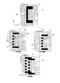
まず、図7(A)は、CPU151のフォントROM157に格納されている上記図6の図柄850のビットマップデータを示し、図中C1〜Cnは、X軸座標(水平方向位置)に対応する列アドレスを示し、図中D1〜Dnは、Y軸座標(垂直方向位置)に対応する行アドレスを示している。
【0093】
図中の座標(C4、D2)などの黒色の画素は、液晶パネル804上の画素が光を透過する高輝度状態となっていることを示し、座標(C3、D2)などの白色の画素は、液晶パネル804上の画素が光を透過しない低輝度状態(黒やグレーなど)になっていることを示している。
【0094】
また、ビットマップデータは、赤、緑、青の3色から構成され、実際には3つのバッファ(記憶領域)から構成されるが、ここでは説明を簡易にするために白黒の画素で説明する。
【0095】
いま、図7(A)のように、図柄の一つである「C」の字状の図柄850の縦線部850Aが1ドットの幅で構成され、立体像として認識される図柄850の飛び出し量(Z軸方向位置)に応じた視差が2ドット(±1ドット)の場合、水平方向の基準位置とした列アドレス=C4とすれば、右眼用画像850Rは、図7(B)のように図柄850を列アドレス=C4から−1ドット(図中左側)だけ水平方向にシフトした図柄となり、左眼用画像850Lは、図7(C)のように、図柄850を列アドレス=C4から+1ドット(図中右側)だけ水平方向にシフトした図柄となる。
【0096】
次に、微細位相差板802の偏光特性の繰り返し間隔が、液晶表示パネル804垂直方向の座標に換算すると1ドット(1水平ライン)おきに設定されている場合、左眼用画像850Lと右眼用画像850Rは、垂直方向の1ドットずつ交互に表示されればよいので、表示制御装置150は、偶数の行アドレスD2、D4……を右眼用画像データの記憶領域とし、奇数の行アドレスD1、D3……を左眼用画像の記憶領域として設定する。なお、これらの記憶領域は表示制御装置150のRAM153等に確保される。
【0097】
したがって、右眼用画像850Rは、図7(B)で示すように、元の図柄850を−1ドットだけ水平方向にシフトして縦線部850Aを列アドレス=C3に設定すると共に、偶数の行アドレスで構成され、行アドレスの一つおきに画像データが生成される。
【0098】
同様に、左眼用画像850Lは、図7(C)で示すように、元の図柄850を+1ドットだけ水平方向にシフトして縦線部850Aを列アドレス=C5に設定すると共に、奇数の行アドレスで構成され、行アドレスの一つおきに画像データが生成される。
【0099】
表示制御装置150は、このように生成した左眼用画像および右眼用画像を、上述のL/R信号に応じて交互に送信する。なお、画像データの送信は垂直同期信号V_SYNCに同期して行われる。
【0100】
一方、合成変換装置170の制御部171は、垂直同期信号V_SYNCを受けると、そのときのL/R信号に基づいて、図3に示した左眼用バッファ173または右眼用バッファ174のいずれか一方に、受信した画像データを取り込む。
【0101】
そして、これらバッファ173、174に書き込まれた画像データは、合成変換装置170の出力バッファ178に書き込まれて合成され、立体視用画像データが生成される。すなわち、図7(D)で示すように、奇数ラインと偶数ラインを上書きすることで同一の記憶領域上で合成され、所定のタイミング(垂直同期信号V_SYNC)おきに画像表示装置8の液晶パネル804に出力される。なお、液晶パネル804への出力は、インターレース若しくはノンインターレースで行われる。
【0102】
次に、合成変換装置170の画像生成手段(モード)について説明する。
【0103】
本発明の実施の形態では、表示装置に表示させる立体画像(又は平面画像)の生成おいて、3種類の画像生成手段(モード)を持つ。VDC156及び合成変換装置170は、CPU151の指示によって、いずれのモードにおいて立体(又は平面)画像を生成し、画像表示装置にデータを送信するかを選択することができる。
【0104】
以下に、この3つのモードの詳細を説明する。モード1は、垂直方向に圧縮された左眼用画像及び右眼用画像を展開して合成し立体視用合成画像を生成するモードである。モード2は、左眼用画像及び右眼用画像を合成し立体視用合成画像を生成するモードである。モード3は、平面画像、すなわち左右の視差のない画像を生成するモードである。
【0105】
まず、モード2から説明すると、モード2は、立体画像を生成するモードである。VDC156は、フォントROM157から読み出した画像データから左眼用画像データと右眼用画像データとを生成し合成変換装置170に出力する。合成変換装置170では、VDC156から受け取った左眼用画像データの奇数番目の走査線に対応するデータと、右眼用画像データの偶数番目の走査線に対応するデータとを合成し、表示装置8に送信する。
【0106】
図8は、本発明の実施の形態のモード2における、VDC156による左眼用画像データ及び右眼用画像データの生成の様子を示す説明図である。フォントROM157には図8(A)のような状態でデータが保存されている。VDC156はこのデータを読み出し(ダウンロード)、着色処理(カラーパレットのデータの割り当て)やポリゴンのレンダリング処理等の処理を行う。(図8(B))さらに、VDC156は、画像データの表示位置をずらして、図8(C)及び(D)、のような左右で視差のある左眼用画像データ及び右眼用画像データを生成する。生成された左眼用画像データ及び右眼用画像データはCPU151からのL/R信号に同期して合成変換装置170に送られる。合成変換装置170では、送られてきた画像データをそのまま出力バッファ178に上書きし、所定のタイミングで表示装置8にデータを送る。
【0107】
図9は、本発明の実施の形態の合成変換装置170が、モード2において、左右の視差のある画像を合成して立体視用の画像の生成の様子を示す説明図である。
【0108】
左眼用バッファ173に保持されている左眼用画像(図9(A))と、右眼用バッファ174に保持されている右眼用画像(図9(B))とを1ライン毎に交互に読み出して、出力バッファ178に交互に書き込む(図9(C))。このとき、表示装置へ出力される画像データは、走査線の1ライン目は左眼用画像の第1ライン(L1)、2ライン目は右眼用画像の第2ライン(R2)、3ライン目は左眼用画像の第3ライン(L3)・・・というように出力バッファ178に書き込まれ、左眼用画像データと右眼用画像データとが合成される。すなわち、左眼用画像データの奇数番目の走査線に対応するデータ(図7の奇数の行アドレスのデータが対応)と右眼用画像データの偶数番目の走査線に対応するデータ(図7の偶数の行アドレスのデータが対応)とが合成されて表示され、左眼用画像データの走査線の偶数番目の走査線に対応するデータと、右眼用画像データの走査線の奇数番目の走査線に対応するデータとは破棄され、表示されない。
【0109】
図10は、モード2における、表示制御装置150から合成変換装置170と画像表示装置8とに送信される信号のタイミング図である。
【0110】
垂直同期信号V_SYNCは、画像データの走査開始タイミングを示すために表示制御装置150にて生成され、画像表示装置8に供給される。画像表示装置8では、垂直同期信号V_SYNCに従って、垂直同期信号V_SYNCの立ち上がりタイミングによって走査線の走査を開始して、画像表示装置8に画像データを表示する。
【0111】
L/R信号は、表示制御装置150から合成変換装置170に送信される信号で、現在VDC156から出力中の信号が、左眼用画像か右眼用画像かを示し、Hi状態では左眼用画像(L)が出力されており、Low状態では右眼用画像(R)が出力されていることを意味している。
【0112】
すなわち、表示制御装置150から合成変換装置170に送信される画像データは、L/R信号に合わせて左眼用画像及び右眼用画像が交互に送信される。合成変換装置170では、L/R信号の切り替えタイミングに応じて、表示制御回路(VDC156)から送信される画像データを取り込んで、左眼用バッファ173又は右眼用バッファ174に書き込む。なお、合成変換装置170が画像データを取り込むためのトリガ信号を、L/R信号とは別に設けてもよい。
【0113】
モード2の場合は、左眼用画像データの奇数番目の走査線に対応するデータと、右眼用画像データの偶数番目の走査線に対応するデータとを出力バッファ178へ転送して立体視用画像データを合成する。すなわち、垂直同期信号V1のタイミングでは、左眼用画像データL1と、右眼用画像データR0(この時点ではまだ右眼用画像データはVDC156で生成されていないので、実際にはR0は空のデータ)とを合成し、出力バッファ178にL1+R0のデータとして格納する。L1+R0の立体視用画像データは、次の垂直同期信号V2のタイミングで画像表示装置8に出力される。
【0114】
次の垂直同期信号V2のタイミングでは、右眼用画像データR2がVDC156より送信され、右眼用画像データR2と、前の垂直同期信号(V1)のタイミングで送信された左眼用画像データL1と合成し、出力バッファ178にデータL1+R2として格納する。L1+R2の立体視用画像データは、次の垂直同期信号V3のタイミングで画像表示装置8に出力される。
【0115】
これを順次繰り返し、出力バッファ178に格納された立体視用画像データは垂直同期信号V_SYNCのタイミングに合わせて画像表示装置8(LCDドライバ181)に出力される。
【0116】
すなわち、モード2では、垂直同期信号のタイミングで送信された右眼用画像データ又は左眼用画像データは、前の垂直同期信号のタイミングで送信された左眼用画像データ又は右眼用画像データと合成され、画像表示装置8に出力される。
【0117】
図11は、本発明の実施の形態でモード2において図柄を表示面の下方へ向けて縦スクロールによる変動表示を行った場合に、表示制御装置150が出力する右眼用画像データ及び左眼用画像データの関係を示す。
【0118】
画像データは、右眼用画像データがR2、R4、左眼用画像データがL1、L3であり、L1、R2、L3、R4、の順に表示される。
【0119】
表示制御装置150は、最初の垂直同期信号V1で左眼用画像データL1を出力し(実際には前回の右眼用画像も合わせて出力し)、左眼用バッファ173が更新される。右眼用バッファ174の内容は前回の垂直同期信号の内容(画像データR1)を保持する。
【0120】
次の垂直同期信号V2では、右眼用画像データR2を出力し(実際には前回の左眼用画像も合わせて出力され)、右眼用バッファ174が画像データR2で更新され、左眼用バッファの内容は前回の垂直同期信号の内容を保持する。
【0121】
この後、垂直同期信号毎に左右の画像データが交互に出力され、左右のフレームバッファは垂直同期信号の一つおきに更新されていく。そして、出力バッファ178では、奇数ラインと偶数ラインが順次上書きされて、左右の画像データが合成される。こうして合成された左右の画像データは、各垂直同期信号の時点の内容で画像表示装置8へ出力される。
【0122】
次に、モード3について説明する。
【0123】
モード3は、平面画像、すなわち左右の視差のない画像を生成するモードである。VDC156は、フォントROM157から読み出して生成した画像データを、そのまま合成変換装置170へ出力する。合成変換装置170では、受け取った該画像データを左眼用画像と右眼用画像とに視差を設ける処理を行うことなく、そのまま出力バッファに格納し、所定のタイミングで表示装置8に出力する。
【0124】
図12は、本発明の実施の形態のモード3における、表示制御装置150から合成変換装置170と画像表示装置8とに送信される信号を示すタイミング図である。
【0125】
垂直同期信号V_SYNCは、画像データの走査開始タイミングを示すために表示制御装置150において生成され、画像表示装置8に供給される。画像表示装置8では、垂直同期信号V_SYNCに従って、垂直同期信号V_SYNCの立ち上がりタイミングによって走査線の走査を開始して、画像表示装置8に画像データを表示する。
【0126】
L/R信号は、表示制御装置150から合成変換装置170に送信される信号で、現在GDP156から出力中の信号が、左眼用画像か右眼用画像かを示し、Hi状態では左眼用画像(L)が出力されており、Low状態では右眼用画像(R)が出力されていることを意味している。
【0127】
すなわち、表示制御装置150から合成変換装置170に送信される画像データは、L/R信号に合わせて左眼用画像及び右眼用画像が交互に送信される。合成変換装置170では、L/R信号の切り替えタイミングに応じて、表示制御回路(VDC156)から送信される画像データを取り込んで、左眼用バッファ173又は右眼用バッファ174に書き込む。なお、合成変換装置170が画像データを取り込むためのトリガ信号を、L/R信号とは別に設けてもよい。
【0128】
モード3の場合は、左眼用画像と右眼用画像との区別はないので、合成変換装置170は、L/R信号のいずれの信号のタイミングで送られてきたデータも、そのまま出力バッファ178に格納する。すなわち、垂直同期信号V1のタイミングでは、VDC156から送られたデータD1はそのまま出力バッファ178にD1として格納され、続いてD2、D3…と受信した画像デーを出力バッファ178に格納して、立体視用画像データとしては垂直同期信号V_SYNCのタイミングに合わせて画像表示装置8(LCDドライバ181)に出力される。
【0129】
図13は、本発明の実施の形態のモード3におけるVDC156による左眼用画像データ及び右眼用画像データの生成の様子を示す説明図である。
【0130】
フォントROM157には図13(A)のような状態で画像データが保存されている。VDC156はこのデータを読み出し(ダウンロード)、着色処理(カレーパレットのデータの割り当て)やポリゴンのレンダリング処理等の処理を行ない画像を生成する(図13(B))。生成された画像データは合成変換装置170に送られる。合成変換装置170では、送られてきた画像データをそのまま出力バッファ178に上書きし(図13(C))、所定のタイミングで表示装置8にデータを送る。
【0131】
次に、モード1について説明する。
【0132】
モード1は、モード2と同様に立体画像を生成するモードである。フォントROM157に格納される画像データの水平方向の画素数を、表示装置8の画面に表示する画素のうち、水平方向の画素は同じであるが、垂直方向(縦方向)の画素は半分である。例えば、画像表示装置8の画面の画素数が水平方向800×垂直方向480ドットであれば、左眼用画像データ及び右眼用画像データは水平方向800×垂直方向240ドットの画素数(垂直方向の画素数が、画像表示装置8の画素数の半分の画素数)に設定されている。
【0133】
すなわち、VDC156は、フォントROM157から読み出した画像データを左眼用画像データと右眼用画像データとに変換する。前述したような左眼画像データ及び右眼画像データの垂直方向の画素数が画像表示装置8の画素数の半分に設定されているので、フォントROM157から読み出した画像データを垂直方向に半分に圧縮して左眼用画像を左眼用バッファ173に書き込み、右眼用画像を右眼用バッファ174に書き込む。なお、フォントROM157から読み出した画像データを垂直方向に半分に圧縮して左眼用バッファ173及び右眼用バッファ174に書き込むのではなく、画像表示装置8の画素数の垂直方向において半分の画素数の画像データをフォントROM157に記憶しておいてもよい。
【0134】
生成された左眼用画像データ及び右眼用画像データは、CPU151からのL/R信号に同期して合成変換装置170に送られる。合成変換装置170では、VDC156から受け取った左眼用画像データの奇数番目の走査線に対応するデータと、右眼用画像データの偶数番目の走査線に対応するデータとを合成し、画像表示装置8に送信する。このとき左眼用画像データと右眼用画像データとの走査線に対応するデータを交互に合成し、画像表示装置8の画面に表示する画素に合わせて出力する。
【0135】
図14は、合成変換装置170が、モード1において、左右の視差のある画像を合成して立体視用の画像の生成の様子を示す説明図である。なお、左眼用画像及び右眼用画像の生成は、前述したモード2(図9)と同一なので、詳細な説明は省略する。左眼用バッファ173に保持されている左眼用画像(図14(A))と、右眼用バッファ174に保持されている右眼用画像(図14(B))とを1ライン毎に交互に読み出して、出力バッファ178に交互に書き込む(図14(C))。左眼用画像及び右眼用画像の縦方向の画素数は、画像表示装置8の画面の縦方向の画素数の半分なので、左眼用画像と右眼用画像との走査線に対応するデータを、画像表示装置8に表示する画像の1走査線毎に合成することで画像表示装置8の画面の画素数と同一の画素数のデータが得られる。
【0136】
なお、図8から図14では、フォントを模式的に表しているが、実際のフォントのデータは図7のような画素の集合である。
【0137】
次に、以上のように構成された本発明の実施の形態の遊技機について、次に画像生成及び合成の動作を説明する。
【0138】
図15は、CPU151及びVDC156によって、右眼用画像データ及び左眼用画像データを生成して合成変換装置170に画像データ出力する処理のフローチャートを示す。
【0139】
まず、CPU151は、これから画像表示装置8に表示させる画像をどのモード(モード1、2又は3)で出力するかを決定し(ステップ101)、決定したモードを合成変換装置170に対して出力する(ステップ102)。
【0140】
次に、CPU151は、ステップ101で決定したモードが何であるかを判定する(ステップ103)。
【0141】
ステップ103においてモードが3であると判定された場合には、まず、VDC156はフォントROM157から指定されたフォントのデータを読み込み(ステップ104)、着色処理(カレーパレットのデータの割り当て)やポリゴンのレンダリング処理等の処理を行って出力する画像データを生成する。(ステップ105)。画像データの生成が完了するとステップ110に移行する。
【0142】
ステップ103においてモードが2であると判定された場合には、まず、CPU151は、L/R信号を発生させるためのL/Rフラグを更新する。すなわち、現在のL/RフラグがLである場合にはL/RフラグをRに設定し、現在のL/RフラグがRである場合にはL/RフラグをLに設定する(ステップ106)。次に、ステップ106で決定したL/Rフラグに基づいて所定のタイミング(垂直同期信号に同期させたタイミング)でL/R信号を出力する(ステップ107)。
【0143】
次に、VDC156は、フォントROM157から指定されたフォントのデータを読み込み(ステップ108)、着色処理(カレーパレットのデータの割り当て)やポリゴンのレンダリング処理等の処理を行う。さらに、モード2では、左右で視差のある画像データを出力するので、ステップ106で決定したL/Rフラグに基づいて、フラグがLの場合は左眼用に視差を設定した左眼用画像データを生成し、フラグがRの場合には右眼用に視差を設定した右眼用画像データを生成する(ステップ109)。左眼用画像データ又は右眼用画像データの生成が完了するとステップ110に移行する。
【0144】
ステップ110では、VDC156は、CPU151から送られる画面更新の割り込み信号(V_SYNC又はH_SYNC)の受信を待機する。画面更新割り込み信号を受信すると、信号に同期して合成変換装置170に対してステップ105又はステップ109で生成された画像データを出力する(ステップ111)。
【0145】
上記の図15の処理によって、VDC156が生成した左眼用画像データ及び右眼用画像データが、CPU151の生成する画面更新割り込み信号のタイミングで合成変換装置170に対して出力される。
【0146】
なお、ステップ104、105は、フォントROM157に記憶されているフォントのデータから左右の目に対して視差を有しない平面画像用の画像データを生成する処理であり、ステップ108、109は、フォントROM157に記憶されているフォントのデータから左右の目で視差を生じる立体画像用の画像データを生成する処理であることから、フォントROM157に記憶されている1つのフォントのデータ(共通に利用されるフォントデータ)から、平面画像用と立体画像用との両方の画像データを各々生成することが可能である。
【0147】
すなわち、互いに視差を有する左眼用画像と右眼用画像とを交互に生成する画像交互生成手段によって生成される左眼用画像及び右眼用画像、並びに、互いに視差を有しない左目用画像及び右目用画像を同時に生成する画像同時生成手段によって生成される画像の各々は、フォント記憶手段(フォントROM157)に記憶されている共通のフォントデータから生成するように構成することができる。この構成により、画像生成に必要となるフォントデータ全体の容量を削減することができる。さらに、この構成により、画像交互生成手段で生成される画像の大きさと、画像同時生成手段で生成される画像の大きさを容易に統一化することもできる。
【0148】
図16は、VDC156によって生成され出力された画像データを、合成変換装置170が合成処理を行い画像表示装置8に画像データを出力する処理のフローチャートを示す。
【0149】
まず、合成変換装置170は、CPU151から送られたモードを受信し(ステップ201)、受信したモードを決定する(ステップ202)。
【0150】
次に、CPU151から送られたL/R信号を受信し(ステップ203)、VDCから送られてきた画像データがL側(左眼用画像データ)であるか、R側(右眼用画像データ)であるかを決定する(ステップ204)。
【0151】
次に、VDC156から送られてきた画像データを受信し、対応する左眼用バッファ173又は右眼用バッファ174に取り込む(ステップ205)。そして、取り込んだ画像をステップ204において決定したどのモードで処理するかを判定する(ステップ206)。
【0152】
ステップ206において、現在のモードがモード3であると判定された場合には、モード3では立体画像処理を行わないので、VDC156から送られ左眼用バッファ173又は右眼用バッファ174に取り込んだ画像をそのままの状態で出力バッファ178に上書きする(ステップ207)。このようにすることで、VDC156から送られた画像データをそのままの状態で画像表示装置8に表示することができる。出力バッファ178に上書きが完了するとステップ215に移行する。
【0153】
ステップ206において、現在のモードがモード1であると判定された場合には、モード1では立体画像処理を行うので、VDC156から送られた画像データが、ステップ204にて受信したL/R信号によって決定されたL側又はR側のどちらの画像データであるかを判別する(ステップ208)、画像データがL側である場合には、取り込んだ画像データを左眼用バッファ173に格納する(ステップ209)。一方、画像データがR側である場合には、取り込んだ画像データを右眼用バッファ174に格納する(ステップ210)。
【0154】
次に、左眼用バッファ173及び右眼用バッファ174に格納された画像は、処理部171によって合成され出力バッファ178に送られ、出力バッファ178の内容を上書きする(ステップ211)。出力バッファ178に上書きが完了するとステップ215に移行する。
【0155】
ステップ206において、現在のモードがモード2であると判定された場合には、モード2では立体画像処理を行うので、VDC156から送られた画像データが、ステップ204にて受信したL/R信号によって決定されたL側又はR側のどちらの画像データであるかを判別する(ステップ212)、画像データがL側である場合には、取り込んだ画像データのうち水平画素の奇数ラインのみを読み出して左眼用バッファに格納する(ステップ213)。一方、画像データがR側である場合には、取り込んだ画像データのうち水平画素の偶数ラインのみを読み出して右眼用バッファに格納する(ステップ214)。
【0156】
次に、左眼用バッファ173及び右眼用バッファ174に格納された画像は、処理部171によって合成され出力バッファ178に送られ、出力バッファ178の内容を上書きする(ステップ211)。出力バッファ178に上書きが完了するとステップ215に移行する。
【0157】
ステップ215では、CPU151から送られる画面更新割り込み信号(V_SYNC又はH_SYNC)の受信を待機する。画面更新割り込み信号を受信すると、信号に同期して表示装置8に対して出力バッファの内容を出力する(ステップ216)。
【0158】
上記の図16の処理によってVDC156によって生成された左眼用又は画像データを合成変換装置170によって立体又は平面画像に変換し、表示装置8に出力され、遊技者に対して立体又は平面の画像を表示することができる。
【0159】
今回開示した実施の形態は、全ての点で例示であって制限的なものではない。本発明の範囲は上記した発明の説明ではなくて特許請求の範囲によって示され、特許請求の範囲と均等の意味及び内容の範囲での全ての変更が含まれることが意図される。
【図面の簡単な説明】
【図1】本発明の実施形態の遊技機全体の構成を示す正面図である。
【図2】同じく制御系の一部を示すブロック図である。
【図3】同じく合成変換装置を示すブロック図である。
【図4】同じく画像表示装置の光学系を説明するための分解斜視図である。
【図5】同じく画像表示装置の光学系の平面図である。
【図6】同じく画像表示装置に図柄を立体的に表示させたときの実際の画像と立体像との関係を示す斜視図である。
【図7】同じく表示制御装置と合成変換装置で行われる、左右画像の生成と、合成の様子を説明図である。
【図8】同じくモード2における、VDC156による左右画像データの生成の様子を示す説明図である。
【図9】同じくモード2における、合成変換装置170が左右の視差のある画像を合成して立体視用の画像の生成の様子を示す説明図である。
【図10】同じくモード2における、表示制御装置150から合成変換装置170と画像表示装置8とに送信される信号のタイミング図である。
【図11】同じくモード2における、図柄を表示面の下方へ向けて縦スクロールによる変動表示を行った場合の、表示制御装置150が出力するデータの関係の説明図である。
【図12】同じくモード3における、表示制御装置150から合成変換装置170と画像表示装置8とに送信される信号のタイミング図である。
【図13】同じくモード3における、VDC156による左右画像データの生成の様子を示す説明図である。
【図14】同じくモード1における、合成変換装置170が左右の視差のある画像を合成して立体視用の画像の生成の様子を示す説明図である。
【図15】右眼用画像データ及び左眼用画像データを生成して合成変換装置170に画像データを出力する処理のフローチャートである。
【図16】合成変換装置170が合成処理を行い画像表示装置8に画像データを出力する処理のフローチャートである。
【符号の説明】
1 遊技機
8 画像表示装置
100 遊技制御装置
150 表示制御装置
151 CPU
170 合成変換装置
171 制御部
172 入力インターフェース
173 右眼用バッファ
174 左眼用バッファ
175 出力バッファ
181 LCDドライブ
182 光源ドライブ
801 光源
810 発光素子
811 偏光フィルタ
812 フレネルレンズ
802 微細位相差板
803 偏光板
804 液晶表示パネル
805 偏光板
806 ディフューザ[0001]
BACKGROUND OF THE INVENTION
The present invention relates to a gaming machine provided with a display device capable of displaying a plurality of types of symbols in a three-dimensional manner, and more particularly to a gaming machine capable of updating images at high speed.
[0002]
[Prior art]
Conventionally, in a game machine such as a pachinko machine, when a so-called reach state or a big hit state is reached, a normal 3D display state is displayed on a 3D display unit via a driver with numbers and pictures read from the frame memory. A gaming machine including a display device that pops out and displays is known (for example, see Patent Document 1).
[0003]
Further, in this type of stereoscopic image display device, a plurality of left-eye sprite image information and right-eye sprite image information corresponding to each left-eye sprite image information are displayed based on storage means and display control information stored in advance. One or more sets of left-eye sprite image information and right-eye sprite image information are read from the storage means, and based on the display priority between the left-eye sprite images and the display priority between the right-eye sprite images, 1 Based on the means for selecting and outputting the left-eye sprite image information and the right-eye sprite image information to be displayed on the screen, and the output left-eye image information and right-eye image information, the sprite image is displayed on the three-dimensional display device. One provided with means for displaying a stereoscopic image has been proposed (see, for example, Patent Document 2).
[0004]
[Patent Document 1]
JP-A-9-103558
[Patent Document 2]
JP-A-10-222139
[0005]
[Problems to be solved by the invention]
However, in the invention described in the
[0006]
Therefore, the present invention has been made in view of the above-described problems, and an object of the present invention is to provide a gaming machine having an image display device that prevents a left-right eye image from being shifted when a screen is updated when an image is displayed.
[0007]
[Means for Solving the Problems]
The first invention displays a left-eye image and a right-eye image for each line, thereby generating a display device that allows a player to recognize the image as a three-dimensional image or a planar image, and generating a timing signal for vertical synchronization in the display device. Update timing signal generating means for generating, and a display control means for generating the left-eye image and the right-eye image and displaying the generated image on the display device in association with the timing signal. In the gaming machine, the display control unit displays the left-eye image and the right-eye image having parallax with each other when the image displayed on the display device is displayed recognizable as a stereoscopic image to the player. In the case where the image alternate generating means for alternately generating each time a signal is generated and the image displayed on the display device are displayed recognizable as a planar image to the player From the image simultaneous generation unit that generates one common image that is used in common as the left-eye image and the right-eye image every time the timing signal is generated, and the image alternate generation unit or the image simultaneous generation unit Receiving means for receiving an image each time the timing signal is generated, image combining means for outputting an image to a display device each time the timing signal is generated, based on an image received by the receiving means; Command means for instructing whether to generate an image by the image alternate generation means or to generate an image by the image simultaneous generation means, and performing display control for scrolling a predetermined symbol on the display device, The image synthesizing means, when the command means instructs the image generation by the image alternate generating means, the image alternate generating means. Of the left-eye image and the right-eye image that are generated alternately, one of the images received by the receiving means when the first timing signal is generated, and immediately before the first timing signal. The other image of the images received by the receiving means when the generated second timing signal is generated is alternately synthesized for each line, and output to the display device. When the command means instructs the image generation by the generation means, the common image received by the receiving means when the timing signal is generated is output to the display device as it is.
[0008]
In a second aspect based on the first aspect, the image synthesizing unit includes a left-eye image buffer and a right-eye image buffer, and the image received by the receiving unit is stored in the left-eye image buffer and the right-eye image. The image of the odd-numbered lines in the buffer for the left-eye image and the image of the even-numbered lines in the buffer for the right-eye image are output to the display device. It is characterized by.
[0009]
According to a third invention, in the first or second invention, the display control means further includes a font storage means for storing image image data, and the display device can display an image for each line. A liquid crystal display panel, a fine retardation plate that varies the polarization characteristics of light transmitted through the liquid crystal display panel for each line, and light having different polarization characteristics is transmitted to the fine retardation plate and the liquid crystal display panel. A light source that allows the transmitted light to reach the left and right eyes of the observer, and the image alternate generation means divides one image data read from the font storage means into two image data for each line. The left-eye image and the right-eye image are generated by shifting one of the two divided image data in the right direction and shifting the other in the left direction. To.
[0012]
【The invention's effect】
Therefore, according to the first and second aspects of the invention, a display device that displays a left-eye image and a right-eye image for each line to allow a player to recognize the image as a stereoscopic image or a planar image, and vertical synchronization in the display device. Update timing signal generating means for generating a timing signal to be generated, display control for generating the left-eye image and the right-eye image, and displaying the generated image on the display device in relation to the timing signal The display control means, when displaying the image displayed on the display device recognizable as a stereoscopic image to the player, the left-eye image and the right-eye image that have parallax with each other Image alternate generation means for alternately generating an image every time the timing signal is generated, and an image displayed on the display device as a planar image to the player When the timing signal is generated, the image simultaneous generation unit and the image alternate generation unit generate one common image that is used in common as the left-eye image and the right-eye image. Or an accepting means for accepting an image from the simultaneous image generating means every time the timing signal is generated, and an image to the display device each time the timing signal is generated based on the image accepted by the accepting means. Image synthesizing means for outputting, and command means for instructing whether to generate an image by the image alternate generating means or to generate an image by the image simultaneous generating means, and the display device displays a predetermined pattern. When the display unit performs scrolling display control and the image synthesizing unit commands the image generation by the image alternating generation unit, Of the left-eye image and the right-eye image that are alternately generated by the image-alternating image generating unit, one of the images received by the receiving unit when the first timing signal is generated, and the first image One of the images received by the receiving means at the time of generation of the second timing signal generated immediately before one timing signal is alternately synthesized for each line, and the display device When the command means instructs the image generation by the image simultaneous generation means, the common image received by the receiving means when the timing signal is generated is output to the display device as it is. The image synthesizing unit includes a left-eye image buffer and a right-eye image buffer, and the image received by the receiving unit is converted into the left-eye image buffer. And the right-eye image buffer, the odd-numbered line image in the left-eye image buffer and the even-numbered line image in the right-eye image buffer are combined and output to the display device Therefore, when displaying a stereoscopic image, a left-eye image and a right-eye image are alternately generated and the image is updated. Therefore, a complicated circuit that simultaneously generates a left-eye image and a right-eye image is provided. do not need. Further, when displaying a planar image, the left-eye image and the right-eye image are images that have no parallax, so even if the left-eye image and the right-eye image are generated simultaneously, the processing load increases. Therefore, the update speed can be increased.
[0013]
Also,The processing load can be reduced by separating the image generation processing and the image combining processing, and furthermore, since the image is combined for each odd (or even) line, a beautiful image is combined. be able to.
[0014]
Also,Even when the stereoscopic image of the design is changed at high speed, it is possible to display a stereoscopic image in which the displacement of the stereoscopic image is difficult to be recognized.
[0015]
According to the third invention,The display control means further includes font storage means for storing image image data. The display device can display an image for each line, and polarization of light transmitted through the liquid crystal display panel. A fine phase difference plate having different characteristics for each line and light having different polarization characteristics are transmitted through the fine phase difference plate and the liquid crystal display panel, and the transmitted light reaches the left and right eyes of the observer. A light source, and the image alternate generation means divides one image data read from the font storage means into two image data for each line, and one of the divided two image data The left-eye image and the right-eye image are generated by shifting to the right and shifting the other to the left.Therefore, a left-eye image that reaches the left eye but does not reach the right eye and a right-eye image that reaches the right eye but does not reach the left eye are generated, and the stereoscopic image is displayed on the liquid crystal display panel. be able to.
At this time, the left-eye image and the right-eye image can be generated from the common font data stored in the font storage means. Thereby, the capacity of the entire font data required for image generation can be reduced.
[0017]
DETAILED DESCRIPTION OF THE INVENTION
Hereinafter, embodiments of the present invention will be described with reference to the drawings.
[0018]
FIG. 1 is a front view showing the overall configuration of a gaming machine (a CR machine with a card ball lending unit) showing an embodiment of the present invention.
[0019]
A
[0020]
A game area surrounded by guardrails is formed on the surface of the
[0021]
The display screen of the
[0022]
Below the
[0023]
In the gaming machine of the present embodiment, a game is played by launching a game ball (pachinko ball) from a hit ball launching device (not shown) toward the game area, and the launched game balls are placed in various places in the game area. The game area is made to flow down while changing the rolling direction by a rolling guide member such as a windmill arranged in the base, and the start opening 16, the general winning
[0024]
When a game ball wins the start opening 16, the general winning
[0025]
When a game ball is won at the
[0026]
The winning of the game ball to the
[0027]
The winning of the game ball to the special
[0028]
When there is a winning game ball at the normal
[0029]
The passing of the game ball to the normal
[0030]
A decoration light-emitting device such as a decoration lamp or LED is provided at a key point of the gaming machine. In other words, a decorative lamp that emits light according to the progress of the game is provided in a center case (around the image display device 8) provided in the center of the game board and an attacker (around the variable winning device 10) provided in the lower part of the game board. Is provided. Further, side case lamps are provided on the upper left and right sides of the game board, and side lamps are provided on the left and right sides of the game board. The game frame is provided with a game frame decoration lamp. These lamps are turned on as the game progresses so that the player's interest in the game continues. In addition, the
[0031]
An
[0032]
An
[0033]
The card
[0034]
FIG. 2 is a block diagram showing a control system centered on the
[0035]
The
[0036]
The
[0037]
The
[0038]
The
[0039]
The
[0040]
Communication from the
[0041]
A power supply device (not shown) of the gaming machine includes a backup power supply unit and a power failure monitoring circuit in addition to the power supply circuit. When the power failure monitoring circuit detects a predetermined voltage drop of the power supply device, the power failure monitoring circuit sequentially outputs a power failure detection signal and a reset signal to the
[0042]
The
[0043]
The
[0044]
The
[0045]
The drawing processing performed by the
[0046]
Note that the
[0047]
Here, as the frame buffer, a plurality of frame buffers are respectively set in a predetermined storage area of the
[0048]
An
[0049]
The RGB signal output from the
[0050]
Further, the
[0051]
Further, the
[0052]
FIG. 3 is a block diagram showing a control system centering on the
[0053]
The
[0054]
Based on the L / R signal from the
[0055]
As shown in FIG. 4, the generation of the stereoscopic image by combining the left-eye image and the right-eye image is performed at every interval of the half-
[0056]
In a normal display state, the left-eye image data transmitted from the
[0057]
In the
[0058]
The
[0059]
Next, the configuration of the image display device will be described.
[0060]
FIG. 4 is an explanatory diagram showing the configuration of the
[0061]
The
[0062]
Of the light emitted from the
[0063]
In addition, even if it does not use a light emitting element and a polarizing filter, what is necessary is just to comprise so that light of a different polarization may be irradiated from a different position, for example, providing two light emitting elements which generate the light of a different polarization, You may comprise so that light may be irradiated to the
[0064]
The light transmitted through the
[0065]
At this time, the light transmitted through the
[0066]
Of the light irradiated on the liquid
[0067]
The liquid
[0068]
A
[0069]
In the fine
[0070]
The half-
[0071]
The repetition of the polarization characteristics of the
[0072]
Alternatively, the repetition of the polarization characteristics of the
[0073]
Thus, since it is necessary to irradiate the display element (horizontal line) of the liquid
[0074]
That is, the
[0075]
The
[0076]
Such a
[0077]
The
[0078]
FIG. 5 is a plan view showing an optical system of the
[0079]
Light emitted from the
[0080]
The
[0081]
On the other hand, light that has passed through the
[0082]
The
[0083]
In this manner, the light emitted from the
[0084]
FIG. 6 is a perspective view showing an example of displaying a two-
[0085]
Here, the
[0086]
In this way, when the
[0087]
That is, the left-
[0088]
Accordingly, in FIG. 6, by changing the amount of shift 2dx in the X-axis direction between the left-
Further, in order to project the three-
[0089]
In FIG. 6 described above, the left-
[0090]
Next, image composition will be described.
[0091]
FIG. 7 is a diagram for explaining how left and right images are generated and combined by the
[0092]
First, FIG. 7A shows the bitmap data of the
[0093]
Black pixels such as coordinates (C4, D2) in the figure indicate that the pixels on the
[0094]
Bitmap data is composed of three colors of red, green, and blue, and is actually composed of three buffers (storage areas). Here, in order to simplify the description, the description will be made with monochrome pixels. .
[0095]
Now, as shown in FIG. 7A, the
[0096]
Next, when the repetition interval of the polarization characteristics of the
[0097]
Therefore, as shown in FIG. 7B, the right-
[0098]
Similarly, as shown in FIG. 7C, the left-
[0099]
The
[0100]
On the other hand, when receiving the vertical synchronization signal V_SYNC, the
[0101]
Then, the image data written in the buffers 173 and 174 is written in the
[0102]
Next, the image generation means (mode) of the
[0103]
In the embodiment of the present invention, there are three types of image generation means (modes) for generating a stereoscopic image (or a planar image) to be displayed on the display device. In accordance with an instruction from the
[0104]
Details of these three modes will be described below.
[0105]
First, the
[0106]
FIG. 8 is an explanatory diagram showing how left-eye image data and right-eye image data are generated by the
[0107]
FIG. 9 is an explanatory diagram illustrating how the
[0108]
The left-eye image (FIG. 9A) held in the left-eye buffer 173 and the right-eye image (FIG. 9B) held in the right-eye buffer 174 are displayed for each line. The data are alternately read and written alternately in the output buffer 178 (FIG. 9C). At this time, the image data output to the display device includes the first line of the left eye image (L1) for the first scanning line, the second line (R2) for the right eye image, and the third line for the second line. The eyes are written in the
[0109]
FIG. 10 is a timing chart of signals transmitted from the
[0110]
The vertical synchronization signal V_SYNC is generated by the
[0111]
The L / R signal is a signal transmitted from the
[0112]
That is, in the image data transmitted from the
[0113]
In
[0114]
At the timing of the next vertical synchronization signal V2, the image data for right eye R2 is transmitted from the
[0115]
This is sequentially repeated, and the stereoscopic image data stored in the
[0116]
That is, in
[0117]
FIG. 11 shows the image data for the right eye and the image for the left eye output from the
[0118]
The image data is displayed in the order of L1, R2, L3, and R4, with the image data for the right eye being R2 and R4 and the image data for the left eye being L1 and L3.
[0119]
The
[0120]
In the next vertical synchronizing signal V2, the right-eye image data R2 is output (actually, the previous left-eye image is also output), the right-eye buffer 174 is updated with the image data R2, and the left-eye image data R2 is output. The contents of the buffer hold the contents of the previous vertical synchronizing signal.
[0121]
Thereafter, left and right image data are alternately output for each vertical synchronization signal, and the left and right frame buffers are updated every other vertical synchronization signal. In the
[0122]
Next,
[0123]
[0124]
FIG. 12 is a timing chart showing signals transmitted from the
[0125]
The vertical synchronization signal V_SYNC is generated in the
[0126]
The L / R signal is a signal transmitted from the
[0127]
That is, in the image data transmitted from the
[0128]
In
[0129]
FIG. 13 is an explanatory diagram showing how left-eye image data and right-eye image data are generated by the
[0130]
The
[0131]
Next,
[0132]
[0133]
That is, the
[0134]
The generated left-eye image data and right-eye image data are sent to the
[0135]
FIG. 14 is an explanatory diagram showing how the
[0136]
8 to 14 schematically show fonts, the actual font data is a set of pixels as shown in FIG.
[0137]
Next, image generation and composition operations will be described for the gaming machine according to the embodiment of the present invention configured as described above.
[0138]
FIG. 15 shows a flowchart of processing in which the
[0139]
First, the
[0140]
Next, the
[0141]
If it is determined in
[0142]
When it is determined in
[0143]
Next, the
[0144]
In step 110, the
[0145]
The left eye image data and right eye image data generated by the
[0146]
[0147]
That is, a left-eye image and a right-eye image generated by an image alternate generation unit that alternately generates a left-eye image and a right-eye image that have parallax with each other, and a left-eye image that has no parallax with each other, and Each of the images generated by the image simultaneous generation unit that simultaneously generates the right-eye image can be configured to be generated from common font data stored in the font storage unit (font ROM 157). With this configuration, it is possible to reduce the capacity of the entire font data necessary for image generation. Furthermore, with this configuration, the size of the image generated by the image alternate generation unit and the size of the image generated by the image simultaneous generation unit can be easily unified.
[0148]
FIG. 16 is a flowchart of processing in which the image data generated and output by the
[0149]
First, the
[0150]
Next, the L / R signal sent from the
[0151]
Next, the image data sent from the
[0152]
If it is determined in
[0153]
If it is determined in
[0154]
Next, the images stored in the left-eye buffer 173 and the right-eye buffer 174 are combined by the
[0155]
If it is determined in
[0156]
Next, the images stored in the left-eye buffer 173 and the right-eye buffer 174 are combined by the
[0157]
In
[0158]
The left eye or image data generated by the
[0159]
The embodiments disclosed herein are illustrative and non-restrictive in every respect. The scope of the present invention is defined not by the above description of the invention but by the scope of the claims, and is intended to include all modifications within the scope and meaning equivalent to the scope of the claims.
[Brief description of the drawings]
FIG. 1 is a front view showing a configuration of an entire gaming machine according to an embodiment of the present invention.
FIG. 2 is a block diagram showing a part of the control system.
FIG. 3 is a block diagram showing a composite conversion device.
FIG. 4 is an exploded perspective view for explaining an optical system of the image display apparatus.
FIG. 5 is a plan view of an optical system of the image display device.
FIG. 6 is a perspective view showing a relationship between an actual image and a three-dimensional image when a pattern is displayed three-dimensionally on the image display device.
FIG. 7 is an explanatory diagram showing how left and right images are generated and combined, similarly performed by the display control apparatus and the combining conversion apparatus.
FIG. 8 is an explanatory diagram showing how left and right image data is generated by the
FIG. 9 is an explanatory diagram showing a manner of generating a stereoscopic image by combining the images with parallax between the left and right in
10 is a timing chart of signals transmitted from the
11 is an explanatory diagram of the relationship of data output by the
12 is a timing chart of signals transmitted from the
13 is an explanatory diagram showing how left and right image data is generated by the
FIG. 14 is an explanatory diagram showing a manner of generating a stereoscopic image by synthesizing images with parallax on the left and right in
15 is a flowchart of processing for generating image data for the right eye and image data for the left eye and outputting the image data to the
FIG. 16 is a flowchart of processing in which the
[Explanation of symbols]
1 gaming machine
8 Image display device
100 game control device
150 Display control device
151 CPU
170 Composite converter
171 Controller
172 Input interface
173 Right eye buffer
174 Left eye buffer
175 Output buffer
181 LCD drive
182 Light source drive
801 Light source
810 Light emitting device
811 Polarizing filter
812 Fresnel lens
802 Fine retardation plate
803 Polarizing plate
804 LCD panel
805 Polarizing plate
806 Diffuser
Claims (3)
前記表示装置において垂直同期となるタイミング信号を発生させる更新タイミング信号発生手段と、
前記左目用画像と前記右目用画像とを生成すると共に、前記生成した画像を、前記タイミング信号に関連して前記表示装置に表示する表示制御手段と、を備えた遊技機において、
前記表示制御手段は、
前記表示装置に表示される画像を、遊技者に立体画像として認識可能に表示する場合に、互いに視差を有する左目用画像と右目用画像とを、前記タイミング信号が発生する毎に交互に生成する画像交互生成手段と、
前記表示装置に表示される画像を、遊技者に平面画像として認識可能に表示する場合に、前記左目用画像及び右目用画像として共通に用いられる一つの共通の画像を、前記タイミング信号が発生する毎に生成する画像同時生成手段と、
前記画像交互生成手段又は前記画像同時生成手段からの画像を、前記タイミング信号が発生する毎に受け入れる受入手段と、
前記受入手段が受け入れた画像に基づいて、前記タイミング信号が発生する毎に表示装置に対して画像を出力する画像合成手段と、
前記画像交互生成手段によって画像を生成するか、又は、画像同時生成手段によって画像を生成するか、を指令する指令手段と、を備え、
前記表示装置において所定の図柄をスクロールさせる表示制御を行い、
前記画像合成手段は、
前記画像交互生成手段による画像生成を前記指令手段が指令した場合には、前記画像交互生成手段によって交互に生成される左目用画像及び右目用画像のうち、第1タイミング信号の発生時に前記受入手段により受け入れられた前記各画像のうちのいずれか一方の画像と、前記第1タイミング信号の直前で発生した第2タイミング信号の発生時に前記受入手段により受け入れられた前記各画像のうちのいずれか他方の画像と、を前記ライン毎に交互に合成して、前記表示装置に出力し、
前記画像同時生成手段による画像生成を前記指令手段が指令した場合には、前記タイミング信号が発生した際に前記受入手段が受け入れた共通の画像を、そのまま前記表示装置に出力することを特徴とする遊技機。A display device that allows the player to recognize the image for the left eye and the image for the right eye for each line as a stereoscopic image or a planar image;
Update timing signal generating means for generating a timing signal for vertical synchronization in the display device ;
In the gaming machine comprising the display control means for generating the left-eye image and the right-eye image and displaying the generated image on the display device in association with the timing signal,
The display control means includes
When the image displayed on the display device is displayed recognizable as a stereoscopic image to the player, a left-eye image and a right-eye image having parallax are alternately generated each time the timing signal is generated. Image alternate generation means;
When the image displayed on the display device is displayed recognizable as a planar image to a player , the timing signal generates one common image that is commonly used as the left-eye image and the right-eye image. Image simultaneous generation means for generating each;
Receiving means for receiving an image from the alternate image generating means or the simultaneous image generating means every time the timing signal is generated;
Image synthesizing means for outputting an image to a display device every time the timing signal is generated based on the image accepted by the accepting means;
Command means for instructing whether to generate an image by the image alternating generation means or to generate an image by the image simultaneous generation means,
Perform display control to scroll a predetermined symbol in the display device,
The image composition means includes
When the command means instructs image generation by the image alternate generation means, the receiving means when the first timing signal is generated among the left eye image and the right eye image generated alternately by the image alternate generation means. Any one of the images received by the receiving means when the second timing signal generated immediately before the first timing signal and the second timing signal generated immediately before the first timing signal are received. Are alternately synthesized for each line, and output to the display device,
When the command means instructs image generation by the image simultaneous generation means, the common image received by the receiving means when the timing signal is generated is output to the display device as it is. Gaming machine.
左目用画像のバッファと右目用画像のバッファとを備え、
前記受入手段が受け入れた画像を、該左目用画像のバッファと右目用画像のバッファとに格納し、
前記左目用画像のバッファにおける奇数番目のラインの画像と、前記右目用画像のバッファにおける偶数番目のラインの画像とを合成して、前記表示装置に出力することを特徴とする請求項1に記載の遊技機。 The image composition means includes
A left-eye image buffer and a right-eye image buffer,
Storing the image received by the receiving means in the left-eye image buffer and the right-eye image buffer;
The odd-numbered line image in the left-eye image buffer and the even-numbered line image in the right-eye image buffer are combined and output to the display device. Game machines.
前記表示装置は、
前記ライン毎に画像を表示可能な液晶表示パネルと、
前記液晶表示パネルを透過する光の偏光特性を、前記ライン毎に異ならせる微細位相差板と、
異なる偏光特性の光を、前記微細位相差板と前記液晶表示パネルとに透過させ、透過した光を観察者の左目及び右目に到達させる光源と、を備え、
前記画像交互生成手段は、
前記フォント記憶手段から読み出した一つの画像データを前記ライン毎に二つの画像データに分割し、
前記分割された二つの画像データのうちの一方を右方向にずらし、また、他方を左方向にずらすことによって、前記左目用画像と前記右目用画像とを生成することを特徴とする請求項1又は2に記載の遊技機。 The display control means further includes a font storage means for storing design image data,
The display device
A liquid crystal display panel capable of displaying an image for each line;
A fine retardation plate that varies the polarization characteristics of light transmitted through the liquid crystal display panel for each line;
A light source that transmits light having different polarization characteristics to the fine phase difference plate and the liquid crystal display panel, and allows the transmitted light to reach the left and right eyes of an observer,
The image alternate generation means includes
One image data read from the font storage means is divided into two image data for each line,
The left-eye image and the right-eye image are generated by shifting one of the two divided image data in the right direction and shifting the other in the left direction. Or the gaming machine of 2.
Priority Applications (1)
| Application Number | Priority Date | Filing Date | Title |
|---|---|---|---|
| JP2003049812A JP4252820B2 (en) | 2003-02-26 | 2003-02-26 | Game machine |
Applications Claiming Priority (1)
| Application Number | Priority Date | Filing Date | Title |
|---|---|---|---|
| JP2003049812A JP4252820B2 (en) | 2003-02-26 | 2003-02-26 | Game machine |
Publications (3)
| Publication Number | Publication Date |
|---|---|
| JP2004254954A JP2004254954A (en) | 2004-09-16 |
| JP2004254954A5 JP2004254954A5 (en) | 2005-10-27 |
| JP4252820B2 true JP4252820B2 (en) | 2009-04-08 |
Family
ID=33115423
Family Applications (1)
| Application Number | Title | Priority Date | Filing Date |
|---|---|---|---|
| JP2003049812A Expired - Fee Related JP4252820B2 (en) | 2003-02-26 | 2003-02-26 | Game machine |
Country Status (1)
| Country | Link |
|---|---|
| JP (1) | JP4252820B2 (en) |
Families Citing this family (4)
| Publication number | Priority date | Publication date | Assignee | Title |
|---|---|---|---|---|
| JP5979801B1 (en) * | 2015-03-25 | 2016-08-31 | 株式会社サンセイアールアンドディ | Game machine |
| JP6983825B2 (en) * | 2019-01-07 | 2021-12-17 | 株式会社ユニバーサルエンターテインメント | Pachinko machine |
| JP7346049B2 (en) * | 2019-03-25 | 2023-09-19 | 株式会社平和 | gaming machine |
| CN115190284B (en) * | 2022-07-06 | 2024-02-27 | 敏捷医疗科技(苏州)有限公司 | Image processing method |
-
2003
- 2003-02-26 JP JP2003049812A patent/JP4252820B2/en not_active Expired - Fee Related
Also Published As
| Publication number | Publication date |
|---|---|
| JP2004254954A (en) | 2004-09-16 |
Similar Documents
| Publication | Publication Date | Title |
|---|---|---|
| JP2004287057A (en) | Game machine | |
| US7355658B2 (en) | Image display unit and game machine | |
| JP4060865B2 (en) | Game machine | |
| JP3940663B2 (en) | Game machine | |
| JP4068998B2 (en) | Game machine | |
| JP4252820B2 (en) | Game machine | |
| JP2004159889A (en) | Game machine | |
| JP3778893B2 (en) | Game machine | |
| JP2004180821A (en) | Game machine | |
| JP3677019B2 (en) | Stereoscopic image display device | |
| JP4336688B2 (en) | Game machine | |
| JP3965150B2 (en) | Game machine | |
| JP3698702B2 (en) | Image display device | |
| JP4323192B2 (en) | Game machine | |
| JP4589372B2 (en) | Game machine | |
| JP4628404B2 (en) | Game machine | |
| JP4585548B2 (en) | Game machine | |
| JP3792206B2 (en) | Game machine | |
| JP4154263B2 (en) | Image display device and game machine equipped with image display device | |
| JP4080858B2 (en) | Game machine | |
| JP2004267442A (en) | Game machine and image display device | |
| JP2004233462A (en) | Image display device and game machine having the device | |
| JP2004174023A (en) | Game machine | |
| JP4027250B2 (en) | Game machine | |
| JP4027414B2 (en) | Game machine |
Legal Events
| Date | Code | Title | Description |
|---|---|---|---|
| A521 | Written amendment |
Free format text: JAPANESE INTERMEDIATE CODE: A523 Effective date: 20050719 |
|
| A621 | Written request for application examination |
Free format text: JAPANESE INTERMEDIATE CODE: A621 Effective date: 20050719 |
|
| A131 | Notification of reasons for refusal |
Free format text: JAPANESE INTERMEDIATE CODE: A131 Effective date: 20080819 |
|
| A521 | Written amendment |
Free format text: JAPANESE INTERMEDIATE CODE: A523 Effective date: 20081017 |
|
| TRDD | Decision of grant or rejection written | ||
| A01 | Written decision to grant a patent or to grant a registration (utility model) |
Free format text: JAPANESE INTERMEDIATE CODE: A01 Effective date: 20090120 |
|
| A01 | Written decision to grant a patent or to grant a registration (utility model) |
Free format text: JAPANESE INTERMEDIATE CODE: A01 |
|
| A61 | First payment of annual fees (during grant procedure) |
Free format text: JAPANESE INTERMEDIATE CODE: A61 Effective date: 20090122 |
|
| R150 | Certificate of patent or registration of utility model |
Ref document number: 4252820 Country of ref document: JP Free format text: JAPANESE INTERMEDIATE CODE: R150 Free format text: JAPANESE INTERMEDIATE CODE: R150 |
|
| FPAY | Renewal fee payment (event date is renewal date of database) |
Free format text: PAYMENT UNTIL: 20120130 Year of fee payment: 3 |
|
| FPAY | Renewal fee payment (event date is renewal date of database) |
Free format text: PAYMENT UNTIL: 20120130 Year of fee payment: 3 |
|
| FPAY | Renewal fee payment (event date is renewal date of database) |
Free format text: PAYMENT UNTIL: 20150130 Year of fee payment: 6 |
|
| R250 | Receipt of annual fees |
Free format text: JAPANESE INTERMEDIATE CODE: R250 |
|
| R250 | Receipt of annual fees |
Free format text: JAPANESE INTERMEDIATE CODE: R250 |
|
| R250 | Receipt of annual fees |
Free format text: JAPANESE INTERMEDIATE CODE: R250 |
|
| LAPS | Cancellation because of no payment of annual fees |