JP4251990B2 - Surface coated cutting tool - Google Patents
Surface coated cutting tool Download PDFInfo
- Publication number
- JP4251990B2 JP4251990B2 JP2003561812A JP2003561812A JP4251990B2 JP 4251990 B2 JP4251990 B2 JP 4251990B2 JP 2003561812 A JP2003561812 A JP 2003561812A JP 2003561812 A JP2003561812 A JP 2003561812A JP 4251990 B2 JP4251990 B2 JP 4251990B2
- Authority
- JP
- Japan
- Prior art keywords
- layer
- cutting tool
- coated cutting
- outer layer
- intermediate layer
- Prior art date
- Legal status (The legal status is an assumption and is not a legal conclusion. Google has not performed a legal analysis and makes no representation as to the accuracy of the status listed.)
- Expired - Lifetime
Links
Images


Classifications
-
- B—PERFORMING OPERATIONS; TRANSPORTING
- B23—MACHINE TOOLS; METAL-WORKING NOT OTHERWISE PROVIDED FOR
- B23B—TURNING; BORING
- B23B27/00—Tools for turning or boring machines; Tools of a similar kind in general; Accessories therefor
- B23B27/14—Cutting tools of which the bits or tips or cutting inserts are of special material
-
- C—CHEMISTRY; METALLURGY
- C23—COATING METALLIC MATERIAL; COATING MATERIAL WITH METALLIC MATERIAL; CHEMICAL SURFACE TREATMENT; DIFFUSION TREATMENT OF METALLIC MATERIAL; COATING BY VACUUM EVAPORATION, BY SPUTTERING, BY ION IMPLANTATION OR BY CHEMICAL VAPOUR DEPOSITION, IN GENERAL; INHIBITING CORROSION OF METALLIC MATERIAL OR INCRUSTATION IN GENERAL
- C23C—COATING METALLIC MATERIAL; COATING MATERIAL WITH METALLIC MATERIAL; SURFACE TREATMENT OF METALLIC MATERIAL BY DIFFUSION INTO THE SURFACE, BY CHEMICAL CONVERSION OR SUBSTITUTION; COATING BY VACUUM EVAPORATION, BY SPUTTERING, BY ION IMPLANTATION OR BY CHEMICAL VAPOUR DEPOSITION, IN GENERAL
- C23C16/00—Chemical coating by decomposition of gaseous compounds, without leaving reaction products of surface material in the coating, i.e. chemical vapour deposition [CVD] processes
- C23C16/22—Chemical coating by decomposition of gaseous compounds, without leaving reaction products of surface material in the coating, i.e. chemical vapour deposition [CVD] processes characterised by the deposition of inorganic material, other than metallic material
- C23C16/30—Deposition of compounds, mixtures or solid solutions, e.g. borides, carbides, nitrides
-
- C—CHEMISTRY; METALLURGY
- C23—COATING METALLIC MATERIAL; COATING MATERIAL WITH METALLIC MATERIAL; CHEMICAL SURFACE TREATMENT; DIFFUSION TREATMENT OF METALLIC MATERIAL; COATING BY VACUUM EVAPORATION, BY SPUTTERING, BY ION IMPLANTATION OR BY CHEMICAL VAPOUR DEPOSITION, IN GENERAL; INHIBITING CORROSION OF METALLIC MATERIAL OR INCRUSTATION IN GENERAL
- C23C—COATING METALLIC MATERIAL; COATING MATERIAL WITH METALLIC MATERIAL; SURFACE TREATMENT OF METALLIC MATERIAL BY DIFFUSION INTO THE SURFACE, BY CHEMICAL CONVERSION OR SUBSTITUTION; COATING BY VACUUM EVAPORATION, BY SPUTTERING, BY ION IMPLANTATION OR BY CHEMICAL VAPOUR DEPOSITION, IN GENERAL
- C23C30/00—Coating with metallic material characterised only by the composition of the metallic material, i.e. not characterised by the coating process
- C23C30/005—Coating with metallic material characterised only by the composition of the metallic material, i.e. not characterised by the coating process on hard metal substrates
-
- Y—GENERAL TAGGING OF NEW TECHNOLOGICAL DEVELOPMENTS; GENERAL TAGGING OF CROSS-SECTIONAL TECHNOLOGIES SPANNING OVER SEVERAL SECTIONS OF THE IPC; TECHNICAL SUBJECTS COVERED BY FORMER USPC CROSS-REFERENCE ART COLLECTIONS [XRACs] AND DIGESTS
- Y10—TECHNICAL SUBJECTS COVERED BY FORMER USPC
- Y10T—TECHNICAL SUBJECTS COVERED BY FORMER US CLASSIFICATION
- Y10T428/00—Stock material or miscellaneous articles
- Y10T428/24—Structurally defined web or sheet [e.g., overall dimension, etc.]
- Y10T428/24942—Structurally defined web or sheet [e.g., overall dimension, etc.] including components having same physical characteristic in differing degree
- Y10T428/2495—Thickness [relative or absolute]
- Y10T428/24967—Absolute thicknesses specified
- Y10T428/24975—No layer or component greater than 5 mils thick
-
- Y—GENERAL TAGGING OF NEW TECHNOLOGICAL DEVELOPMENTS; GENERAL TAGGING OF CROSS-SECTIONAL TECHNOLOGIES SPANNING OVER SEVERAL SECTIONS OF THE IPC; TECHNICAL SUBJECTS COVERED BY FORMER USPC CROSS-REFERENCE ART COLLECTIONS [XRACs] AND DIGESTS
- Y10—TECHNICAL SUBJECTS COVERED BY FORMER USPC
- Y10T—TECHNICAL SUBJECTS COVERED BY FORMER US CLASSIFICATION
- Y10T428/00—Stock material or miscellaneous articles
- Y10T428/26—Web or sheet containing structurally defined element or component, the element or component having a specified physical dimension
- Y10T428/263—Coating layer not in excess of 5 mils thick or equivalent
- Y10T428/264—Up to 3 mils
- Y10T428/265—1 mil or less
Description
技術分野
本発明は、鋼材の切削などに好適な被覆切削工具に関するものである。
背景技術
被覆切削工具には種々のものが提案されており、例えば、基体に被覆を設けた工具を開示する文献として、特許文献1〜6が挙げられる。そのような被覆構造の一例として、内側層にTi系膜、外側層にAl2O3膜、最外層にTi系膜を配したものが知られている。この内側層と外側層は密着力が悪く、様々な接着層が提案されている。
(特許文献1)
特公昭57−42152号公報
(特許文献2)
特公昭58−67858号公報
(特許文献3)
特公昭59−44385号公報
(特許文献4)
特公昭60−37189号公報
(特許文献5)
特公平1−12835号公報
(特許文献6)
特開平5−8103号公報
しかし、近年、被削材の複雑形状による加工接触回数の増加、難削材化による工具への溶着量の増加など、被覆膜に対する切削負荷が極めて大きくなっている。具体的には溶着量増加に伴い切削抵抗が大きくなり膜剥離(膜の層間剥離)や膜の摩耗が急激に発生し、工具寿命を短くしている。
発明の開示
本発明の主目的は、溶着に伴う膜剥離を抑制できる表面被覆切削工具を提供することにある。
本発明表面被覆切削工具は基体表面に被覆層を有する。この被覆層は、各々少なくとも一層の内側層、中間層および外側層を具える。この内側層は、周期律表IVa、Va、VIa族の炭化物、窒化物、炭窒化物、硼化物、硼窒化物、硼窒炭化物、酸化物、炭酸化物、酸窒化物、炭窒酸化物よりなる群から選択される少なくとも一種の材料で構成され、かつ柱状組織からなる層を含む。外側層は、酸化アルミニウム、酸化ジルコニウム、酸化ハフニウムおよびそれらの固溶体よりなる群から選択される少なくとも一種の酸化物層からなる。中間層は、下記の式1を満たす硼窒化チタンTiBxNy(x、y:atomic%)からなる。そして、この中間層の平均膜厚を0.1〜1μmとすることを特徴とする。
![]()
(内側層)
内側層2は、周期律表IVa、Va、VIa族の炭化物、窒化物、炭窒化物、硼化物、硼窒化物、硼窒炭化物、酸化物、炭酸化物、酸窒化物、炭窒酸化物よりなる群から選択される少なくとも一種の材料で構成される。より具体的には、TiC、TiN、TiCN、TiCNO、TiB2、TiBN、TiCBN、ZrC、ZrO2、HfC、HfNなどが挙げられる。
内側層には、柱状組織からなる層を含むことが好ましい。柱状組織からなる層は耐摩耗性に優れる。柱状組織となる層の具体的材質としては炭窒化チタンまたは炭窒酸化チタンが好適である。柱状組織の内側層は、主に製造条件における反応ガス組成や温度を調整したり、成膜時間をある程度長くすることで得ることができる。柱状組織のアスペクト比は5以上であることが好ましい。アスペクト比5以上の柱状晶としたのは、主に外側層が摩滅もしくは剥離した後の耐摩耗性を考慮したためである。
アスペクト比は、柱状晶TiCN層の上端の水平方向粒径をd1、下端の水平方向粒径をd2としたとき、(d1+d2)/2と結晶粒の長さ(垂直方向長さ=膜厚)との比をとる。
アスペクト比の測定方法は次の通りである。切削工具の縦断面に対して平行あるいは適当な角度(10°以下が好ましい)をつけて研磨し、適当な腐食液を用いて結晶粒界を浮かび上がらせた後に、走査型電子顕微鏡で観察して、適切な倍率で撮影した写真から結晶粒径の成長方向、アスペクト比を算出する。
内側層の平均膜厚は1.0〜20.0μmであることが望ましい。この下限値を下回ると柱状晶を得ることが難しくなり、外側層の剥離後に耐摩耗性を維持することが困難となる。逆に上限値を超えても膜が脆くなって耐摩耗性が低下する。
(外側層)
外側層4は、酸化アルミニウム、酸化ジルコニウム、酸化ハフニウムおよびそれらの固溶体よりなる群から選択される少なくとも一種の酸化物層からなる。これらの酸化物は、化学的に安定であり、鉄との反応性が低く、溶着が生じ難い。中でもAl2O3が好ましい。特にα型Al2O3を主成分とする外側層が好適である。α型Al2O3は高温安定型の材料であり、強度、耐熱性に優れる。α型Al2O3を主成分とするとは、外側層に占めるα型Al2O3の重量比が50%以上のものを言う。外側層の平均膜厚は0.5〜10.0μmが好ましい。この下限値を下回ると溶着を抑制する効果が少なく、上限値を超えても欠損や剥離が生じやすくなる。
(中間層)
内側層2と外側層4の間に介在される中間層3は、式1を満たす硼窒化チタンTiBxNy(x、y:atomic%)からなる。ただし、不純物として含まれる塩素は化学式に加えていない。
![]()
![]()
内側層と外側層の密着性向上を目的とした中間層には、TiB2も考えられる。しかし、図2のグラフに示すように、TiB2は鉄との反応性がTiNに比べ35倍程度高く、被削材が溶着し易い。一方、中間層にTiBNの代わりとしてTiNを配することは、内側・外側層間の密着力を低下させ、かつ硬度低下が著しいため、工具の寿命延命ができなくなる。本発明では、中間層のB量を制限することで、外側層が剥離または摩滅して中間層が露出した際の鉄との反応性を下げて被削材の溶着を抑制する。また、TiBN層が露出した場合、B量を少なくしたための硬度低下(硬度:TiB2>TiN)に起因する耐摩耗性低下は、TiBNの膜厚と柱状晶組織を有する内側層で補って耐摩耗性の向上を図る。
加えて、上記のTiBN層とすることで、外側層となる酸化物膜の粒度を抑制でき、それにより被覆層表面の凹凸を少なくし、切削抵抗の負荷を下げることが可能となる。これは、TiNへのBの微量添加により、TiBN膜が微粒化した組織となり、その外側層の核発生を均一化し、かつ微細化することができるからである。より具体的には、中間層の基準長さ1μmの表面粗さで、最高部の水平線である山頂線と最低部の水平線である谷底線との間の垂直距離を50〜500nmとする。このことにより外側層を均一に成長させ、表面被覆工具の最表面の凹凸を極力無くすことが可能となる。そして、中間層と外側層との密着力も向上できる。
また、TiBN膜の厚みを抑制し、内層に柱状組織を有するTi系の膜を1層以上配することにより、耐摩耗性の向上を図ることができる。この中間層の平均膜厚は0.1〜1μmとすることが好適である。この下限値を下回ると、内側層と外側層の密着性を高める効果が少なく、上限値を上回ると被覆層の耐摩耗性を向上させる効果が少ないからである。
あるいは、この中間層3は式1を満たす硼窒化チタンTiBxNy(x,y:atomic%)とTi・B・Nを除く内側層および/または外側層を構成する元素を含み、
![]()
この中間層は、硼窒化チタンTiBxNy(x、y:atomic%)の代わりに硼窒酸化チタンTiBxNyOz(x、y、z:atomic%)とし、式1および式3を満たすことも好ましい。
x/(x+y+z)の値が0.0005以下になると、B量を少なくしたために硬度低下が生じてしまう。逆に、x/(x+y+z)の値が0.04以上になると、被削材との反応性が高くなり中間層が露出したときに被削材と反応して、溶着物が工具の刃先に強固に付着し、内側層の剥離現象を促進してしまう。x/(x+y+z)の上限値を0.02以下とすることも好適である。また、z/(x+y+z)が0となると酸素を含まない硼窒化チタンTiBxNy(x、y:atomic%)と変わらず、0.5より大きくなると、膜の硬度は増すが靭性が低下し、断続切削時の耐欠損性が低くなってしまう。
さらに、中間層は、内側層側に酸素を含まない硼窒化チタンTiBxNy(x、y:atomic%)を配し、外側層側に酸素を含む硼窒酸化チタンTiBxNyOz(x、y、z:atomic%)を配することが好ましい。この構造により、内側層と外側層の両方の密着力を高め、工具の寿命を更に延命できる。特に、内層側から外層側に向かって酸素の含有量が段階的または連続的に増加する傾斜組成構造の中間層を設けることが好ましい。
(識別層)
外側層よりも更に外側に、周期律表IVa、Va、VIa族の炭化物、窒化物、炭窒化物、酸化物、炭酸化物、酸窒化物、炭窒酸化物よりなる群から選択される少なくとも一種の材料で構成される識別層5を有することが好ましい。一般に、Al2O3は黒色又は褐色を呈し、被覆層の最外層に全面的に配置すると、使用済みコーナを識別することが難しい。そのために識別層を設け、使用済みコーナの識別を容易にすると共に、耐摩耗性を高めている。識別層は単層でも複層でもかまわない。識別層の平均膜厚は0.2〜5.0μm程度が適切である。
(被覆層の表面粗さ)
被覆層の最表面のうち刃先稜線部近傍以外で被削材と接触する個所の平均面粗さが、工具断面から観察する方法によって測定される基準長さ5μmに対しRmax0.2〜1.3μmであることが好適である。
また、被覆層の最表面のうち刃先稜線部近傍における面粗さが、工具断面から観察する方法によって測定される基準長さ5μmに対しRmax0.2μm以下であることが望ましい。この規定値を上回ると溶着しやすくなり、切り屑の流れも悪くなる。刃先稜線部近傍は、実質的に切削に関与して切削抵抗が最も作用する個所であり、その表面を平滑にすることで切削抵抗を低減すると共に高精度の加工を可能にする。
(基体)
基体1は硬質相と結合相とからなる超硬合金とする。硬質相は、炭化タングステンを主成分とし、周期律表IVa、Va、VIa族金属の炭化物、窒化物、炭窒化物及びそれらの固溶体(WCを除く)よりなる群から選択された少なくとも1種を含むものとする。炭化タングステンを主成分とするとは、硬質相中に占める炭化タングステンの重量比が50%以上であるものを言う。結合相は、鉄族金属から選択された少なくとも1種を含むものとする。
(用途)
本発明切削工具の具体的用途は、エンドミル、切削用のチップ、フライス用のチップ、旋削用のチップなどが挙げられる。
(被削材)
本発明切削工具が特に有効な被削材としては、低炭素鋼、中炭素鋼、高炭素鋼などの鋼一般の他、特に溶着の生じやすいダクタイル鋳鉄、ステンレス、インコネルなどが挙げられる。
発明を実施するための最良の形態
以下、本発明の実施の形態を説明する。
(試験例1)
下記に示す基体Aの材料粉末をボールミルにより15H湿式混合し、乾燥した後、圧粉体にプレス成形した。本例の圧粉体の形状は、全周型チップブレーカのISO・CNMG120408に定める形状とした。この圧粉体を焼結炉内に挿入し1526.85℃(1800K)の温度で0.5H真空焼結(100Pa)を行い、焼結体を作製した。その後、刃先稜線部のみにSiCブラシでホーニング処理を行った。
(基体の原料粉末:重量%)
A TaC:2.3、NbC:1.2、TiC:2、TiN:2、ZrC:0.2 Co:6 残りWC
B TaC:2.3、NbC:1.2、TiC:2、TiN:2、TiCN:0.2 Co:6 Ni:3残りWC
C TaC:2.3、NbC:1.2、TiC:2、TiN:2、ZrC:0.2 Fe:6 残りWC
この基体A上に、CVD炉内において表1に示すガス組成、圧力条件、温度で被覆層を形成した。ここでは、被覆層組成として、表1中のTiCN、TiBN、α−Al2O3、TiNを選択して、それぞれ順に内層、中間層、外側層、識別層とした。厚みは、内側層:10μm、中間層:1.0μm、外側層:7μm、識別層:3μmである。内側層のTiCNは全て柱状晶組織であり、そのアスペクト比は7.0である。また、TiBNは、表2に示すように、TiBxNy(x、y:atomic%)で0.001<x/(x+y)<0.04を満たすものと満たさないものの両方を作製した。得られた被覆層最表面の面粗さは、工具断面から観察する方法によって測定される基準長さ5μmに対し、刃先稜線部でRmax0.15μm、刃先稜線部以外の個所でRmax0.70μmである。また、TiBNは基準長さ1μmの表面粗さで、山頂線と谷底線との間の垂直距離が50〜150nmであった。
(試験例2)
試験例1に記載の基体A上にCVD炉内において表1に示すガス組成、圧力条件、温度で被覆層を形成する。ここでは、被覆組成として、表1中のTiCN、TiBN、α−Al2O3、TiNを選択して、それぞれ順に内側層、中間層、外側層、識別層とした。また中間層中の内側層構成元素の量を中間層の内側層側から中間層の膜厚の中央に向かう方向に連続または段階的に減少する方法は、中間層形成ガスを流すのに加え、内側層形成ガスの量を、中間層の膜が内側層側から中間層の膜厚の中央に向かう方向に、連続または段階的に減らしていくことで得られ、および/または中間層中の外側層構成元素の量を中間層の外側層側から中間層の膜厚の中央に向かう方向に連続または段階的に減少する方法は、中間層形成ガスを流すのに加え、中間層の膜が膜厚の中央から中間層の外側層側に向かう方向に外側層形成ガスの量を連続または段階的に増やしていくことで得られる。
この上記記載の方法で得られた膜と比較するために試験例1の表2の試料1−3を用いた。尚、上記記載の方法で得られた膜は膜厚、アスペクト比、x/(x+y)=0.01、工具最表面の面粗さ、TiBNの山頂線と谷底線との垂直距離を全て試料No.1−3と同様になるように温度、圧力の調整を行った。
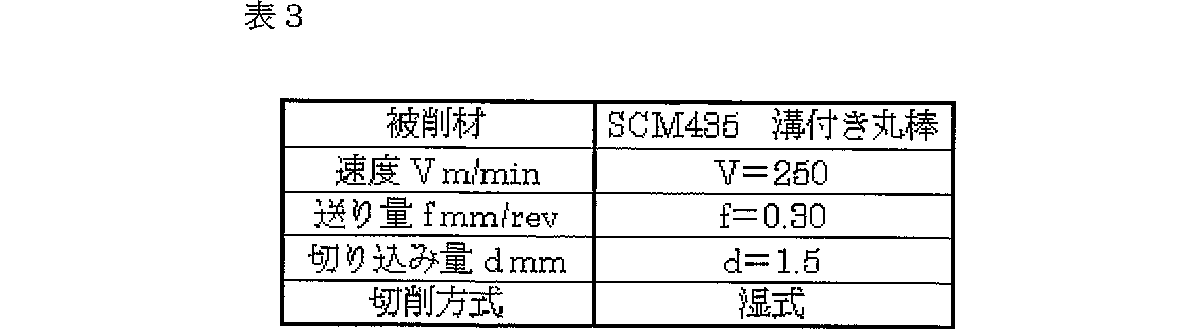
上記の得られた試料と試料No.1−3を表3に示す条件にて断続試験を行い、工具寿命までの加工時間を測定した結果、No.1−3は30分間の加工ができたのに対して、40分間加工が可能になった。
また、表4に示す条件にて連続切削試験を行って、工具寿命までの加工時間を測定した結果、No.1−3が20分間の切削可能時間に対して、30分間の連続切削が可能となった。
このように、前記中間層は式1を満たす硼窒化チタンTiBxNy(x,y:atomic%)とTi・B・Nを除く内側層および/または外側層を構成する元素を含み
![]()
(試験例3)
さらに、試験例1に示す基体A〜Cを用いて、表5に示す構造の被覆層を形成し、試験例1と同様の切削試験を行った。各組成の被覆層の成膜条件は試験例1の表1に示す通りである。各試料のx/(x+y)、アスペクト比、表面粗さ及び試験結果を表6に示す。表6中の「中間層表面粗さ」は、基準長さ1μmの表面粗さで、山頂線と谷底線との間の垂直距離で表している。
▲1▼内側層は、柱状晶のTiCNが好適であり、そのアスペクト比が5以上のものが好ましい。
▲2▼中間層の厚みは0.1〜2.0μmが好適である。
▲3▼外側層の厚みは0.5〜10μmが望ましい。また、外側層の材質はα−Al2O3が望ましい。
▲4▼表面粗さは、刃先稜線部近傍以外でRmax0.2〜1.3μmとし、刃先稜線部近傍でRmax0.2μm以下とすることが好ましい。
(試験例4)
次に、試験例1に示した基体AでISO・CNMG120408に定める形状の焼結体を作製し、その焼結体表面に被覆層を作製した。被覆層は、内側層(TiCN)、中間層(TiBNおよびTiBNOの少なくとも一方)、外側層(α−Al2O3)、識別層(TiN)からなり、厚みは内側層:10μm、中間層:1.0μm、外側層:7μm、識別層:3μmとした。中間層は、内側層側から外側層側に向かって酸素含有量が連続的に多くなる傾斜組成構造のものも作製した。各試料の中間層の組成を表7に示す。
TiBxNyOzで0.001<x/(x+y)<0.04および0.0005<x/(x+y+z)<0.04、0<z/(x+y+z)<0.5を満たすものは、次の条件により成膜する。
TiCl4:2容量%、BCl3:0.005〜2容量%、N2:5〜15容量%、NO:5〜15容量%、H2:残、圧力:4〜10.7kPa、温度:800〜930℃。
TiBxNyOzで0.001<x/(x+y)<0.04および0.0005<x/(x+y+z)<0.04、0<z/(x+y+z)<0.5を満たさないものは、次の条件により成膜する。
TiCl4:2容量%、BCl3:5容量%、N2:5〜15容量%、NO:1〜10容量%、H2:残、圧力:13.3kPa、温度:950℃。
また、傾斜組成構造の中間層を得るには、徐々に酸素量を変化させればよい。すなわち、酸化窒素NOのガス量と成膜圧力・成膜温度を変化させることで可能となる。
内側層は全て柱状晶組織であり、そのアスペクト比は7.0である。得られた被覆層最表面の面粗さは、工具断面から観察する方法によって測定される基準長さ5μmに対し、刃先綾線部でRmax0.15μm、刃先綾線部以外の個所でRmax0.90μmである。TiBNOは基準長さ1μmの表面粗さで、山頂線と谷底線との間の垂直距離が100〜300nmであった。TiBNは基準長さ1μmの表面粗さで、山頂線と谷底線との間の垂直距離が50〜150nmであった。
このような試料を用いて表3に示す条件にて断続切削試験を、表4に示す条件にて連続切削試験を行って、工具寿命までの加工時間を測定した。その結果も表7に示す。
産業上の利用可能性
以上説明したように、本発明切削工具によれば、内側層と外側層との接着層として硼窒化チタンと硼窒酸化チタンの少なくとも一方を用い、その硼素の含有量や酸素の含有量を特定することで、内側層と外側層との接着性を高めることができる。また、硼素の含有量を特定した硼窒化チタンを用いることで、外側層が剥離した場合でも被削材との反応を極力低くし、被削材の溶着を防止することができる。特に、内側層側に酸素を含まない硼窒化チタンを配し、外側層側に酸素を含む硼窒酸化チタンを配した中間層を用いれば、一層工具寿命を改善することができる。
【図面の簡単な説明】
図1は、本発明切削工具の被覆構造を示す模式説明図である。
図2は、各種セラミックスと鉄との反応性および熱伝導率の関係を示すグラフである。TECHNICAL FIELD The present invention relates to a coated cutting tool suitable for cutting steel materials.
Background Art Various types of coated cutting tools have been proposed. For example, Patent Documents 1 to 6 are cited as documents that disclose a tool in which a substrate is coated. As an example of such a covering structure, a structure in which a Ti-based film is disposed on the inner layer, an Al 2 O 3 film is disposed on the outer layer, and a Ti-based film is disposed on the outermost layer is known. The inner layer and the outer layer have poor adhesion, and various adhesive layers have been proposed.
(Patent Document 1)
Japanese Patent Publication No.57-42152 (Patent Document 2)
Japanese Patent Publication No. 58-67858 (Patent Document 3)
Japanese Patent Publication No.59-44385 (Patent Document 4)
Japanese Patent Publication No. 60-37189 (Patent Document 5)
Japanese Examined Patent Publication No. 1-1835 (Patent Document 6)
However, in recent years, the cutting load on the coating film has become extremely large, such as an increase in the number of machining contacts due to the complicated shape of the work material and an increase in the amount of welding to the tool due to the difficult-to-cut material. . Specifically, the cutting resistance increases as the welding amount increases, and film peeling (film delamination) and film wear occur rapidly, shortening the tool life.
DISCLOSURE OF THE INVENTION A main object of the present invention is to provide a surface-coated cutting tool capable of suppressing film peeling accompanying welding.
The surface-coated cutting tool of the present invention has a coating layer on the substrate surface. The covering layers each comprise at least one inner layer, intermediate layer and outer layer. This inner layer is composed of carbides, nitrides, carbonitrides, borides, boronitrides, boronitrides, oxides, carbonates, oxynitrides, oxynitrides of the periodic table groups IVa, Va, VIa A layer composed of at least one material selected from the group consisting of a columnar structure. The outer layer is made of at least one oxide layer selected from the group consisting of aluminum oxide, zirconium oxide, hafnium oxide, and solid solutions thereof. The intermediate layer is made of titanium boronitride TiBxNy (x, y: atomic%) satisfying the following formula 1. And the average film thickness of this intermediate | middle layer shall be 0.1-1 micrometer.
![]()
(Inner layer)
The
The inner layer preferably includes a layer made of a columnar structure. A layer composed of a columnar structure is excellent in wear resistance. Titanium carbonitride or titanium carbonitride is preferred as the specific material for the layer that forms the columnar structure. The inner layer of the columnar structure can be obtained mainly by adjusting the reaction gas composition and temperature under the manufacturing conditions, or by increasing the film formation time to some extent. The aspect ratio of the columnar structure is preferably 5 or more. The reason why the columnar crystals have an aspect ratio of 5 or more is mainly due to consideration of wear resistance after the outer layer is worn or peeled off.
The aspect ratio is (d1 + d2) / 2 when the horizontal grain size at the upper end of the columnar TiCN layer is d1 and the horizontal grain size at the lower end is d2, and the length of the crystal grains (vertical length = film thickness). And take the ratio.
The method for measuring the aspect ratio is as follows. After polishing with a parallel or appropriate angle (preferably 10 ° or less) with respect to the longitudinal section of the cutting tool, and using a suitable corrosive solution to raise the crystal grain boundaries, observe with a scanning electron microscope. The growth direction and aspect ratio of the crystal grain size are calculated from a photograph taken at an appropriate magnification.
The average film thickness of the inner layer is desirably 1.0 to 20.0 μm. Below this lower limit, it becomes difficult to obtain columnar crystals, and it becomes difficult to maintain wear resistance after the outer layer is peeled off. Conversely, even if the upper limit is exceeded, the film becomes brittle and wear resistance decreases.
(Outer layer)
The outer layer 4 is made of at least one oxide layer selected from the group consisting of aluminum oxide, zirconium oxide, hafnium oxide, and solid solutions thereof. These oxides are chemically stable, have low reactivity with iron, and hardly cause welding. Of these, Al 2 O 3 is preferable. In particular, an outer layer mainly composed of α-type Al 2 O 3 is suitable. α-type Al 2 O 3 is a high-temperature stable material and has excellent strength and heat resistance. “α-type Al 2 O 3 as a main component” means that the weight ratio of α-type Al 2 O 3 in the outer layer is 50% or more. The average thickness of the outer layer is preferably 0.5 to 10.0 μm. Below this lower limit, the effect of suppressing welding is small, and even when the upper limit is exceeded, defects and delamination tend to occur.
(Middle layer)
The intermediate layer 3 interposed between the
![]()
![]()
TiB 2 is also considered as an intermediate layer for the purpose of improving the adhesion between the inner layer and the outer layer. However, as shown in the graph of FIG. 2, TiB 2 has a reactivity with iron that is about 35 times higher than that of TiN, and the work material is easily welded. On the other hand, disposing TiN instead of TiBN in the intermediate layer decreases the adhesion between the inner and outer layers and significantly reduces the hardness, so that the tool life cannot be extended. In the present invention, by limiting the amount of B in the intermediate layer, the reactivity with iron when the outer layer is peeled or worn away and the intermediate layer is exposed is lowered, thereby suppressing welding of the work material. Further, when the TiBN layer is exposed, the decrease in wear resistance due to the decrease in the amount of B (hardness: TiB 2 > TiN) is compensated by the inner layer having the TiBN film thickness and the columnar crystal structure. Improve wearability.
In addition, by using the above TiBN layer, the particle size of the oxide film serving as the outer layer can be suppressed, thereby reducing the irregularities on the surface of the coating layer and reducing the load of cutting resistance. This is because by adding a small amount of B to TiN, the TiBN film becomes a finely divided structure, and the nucleation of the outer layer can be made uniform and fine. More specifically, the vertical distance between the peak line, which is the highest horizontal line, and the valley line, which is the lowest horizontal line, is 50 to 500 nm with a surface roughness of 1 μm as the reference length of the intermediate layer. This makes it possible to grow the outer layer uniformly and eliminate as much as possible the unevenness on the outermost surface of the surface-coated tool. And the adhesive force of an intermediate | middle layer and an outer side layer can also be improved.
Further, the wear resistance can be improved by suppressing the thickness of the TiBN film and disposing one or more Ti-based films having a columnar structure in the inner layer. The intermediate layer preferably has an average film thickness of 0.1 to 1 μm. If the lower limit is not reached, the effect of increasing the adhesion between the inner layer and the outer layer is small, and if the upper limit is exceeded, the effect of improving the wear resistance of the coating layer is small.
Alternatively, the intermediate layer 3 includes titanium boronitride TiBxNy (x, y: atomic%) satisfying formula 1 and elements constituting the inner layer and / or the outer layer excluding Ti · B · N,
![]()
This intermediate layer is preferably made of boronitride titanium TiBxNyOz (x, y, z: atomic%) instead of titanium boronitride TiBxNy (x, y: atomic%), and satisfying Equations 1 and 3.
When the value of x / (x + y + z) is 0.0005 or less, the hardness is lowered because the amount of B is reduced. On the contrary, when the value of x / (x + y + z) is 0.04 or more, the reactivity with the work material is increased, and when the intermediate layer is exposed, it reacts with the work material and the welded material is applied to the cutting edge of the tool. It adheres firmly and promotes the peeling phenomenon of the inner layer. It is also preferable that the upper limit value of x / (x + y + z) is 0.02 or less. Further, when z / (x + y + z) is 0, it is not different from titanium boronitride TiBxNy (x, y: atomic%) which does not contain oxygen, and when it is larger than 0.5, the hardness of the film increases but the toughness decreases, and intermittent The chipping resistance during cutting is reduced.
Further, the intermediate layer is provided with titanium boronitride TiBxNy (x, y: atomic%) not containing oxygen on the inner layer side, and boronitride titanium TiBxNyOz containing oxygen on the outer layer side (x, y, z: atomic). %) Is preferred. With this structure, the adhesion of both the inner layer and the outer layer can be increased, and the tool life can be further extended. In particular, it is preferable to provide an intermediate layer having a gradient composition structure in which the oxygen content increases stepwise or continuously from the inner layer side toward the outer layer side.
(Identification layer)
Further outside the outer layer, at least one selected from the group consisting of carbides, nitrides, carbonitrides, oxides, carbonates, oxynitrides, oxynitrides of the periodic table groups IVa, Va, VIa It is preferable to have the discriminating layer 5 made of the above material. In general, Al 2 O 3 has a black or brown color, and when it is disposed entirely on the outermost layer of the coating layer, it is difficult to identify used corners. Therefore, an identification layer is provided to facilitate identification of used corners and improve wear resistance. The identification layer may be a single layer or multiple layers. The average thickness of the identification layer is suitably about 0.2 to 5.0 μm.
(Surface roughness of coating layer)
Of the outermost surface of the coating layer, the average surface roughness of the portion in contact with the work material other than the vicinity of the edge of the cutting edge is Rmax 0.2 to 1.3 μm with respect to a reference length of 5 μm measured by a method of observing from the tool cross section. It is preferable that
Further, it is desirable that the surface roughness in the vicinity of the cutting edge ridge line portion of the outermost surface of the coating layer is Rmax 0.2 μm or less with respect to a reference length of 5 μm measured by a method of observing from the tool cross section. When this specified value is exceeded, welding becomes easier and the flow of chips becomes worse. The vicinity of the edge portion of the cutting edge is a portion where the cutting resistance is most affected by cutting and the surface is smoothed to reduce the cutting resistance and enable high-precision machining.
(Substrate)
The substrate 1 is a cemented carbide alloy composed of a hard phase and a binder phase. The hard phase is mainly composed of tungsten carbide, and includes at least one selected from the group consisting of carbides, nitrides, carbonitrides and solid solutions thereof (except WC) of Group IVa, Va, and VIa metals of the periodic table. Shall be included. “Containing tungsten carbide as a main component” means that the weight ratio of tungsten carbide in the hard phase is 50% or more. The binder phase includes at least one selected from iron group metals.
(Use)
Specific applications of the cutting tool of the present invention include end mills, cutting tips, milling tips, turning tips and the like.
(Work material)
Examples of work materials in which the cutting tool of the present invention is particularly effective include general steels such as low carbon steel, medium carbon steel, and high carbon steel, as well as ductile cast iron, stainless steel, and Inconel that are particularly susceptible to welding.
BEST MODE FOR CARRYING OUT THE INVENTION Embodiments of the present invention will be described below.
(Test Example 1)
The material powder of the base A shown below was wet mixed by a ball mill for 15H, dried, and press-molded into a green compact. The shape of the green compact of this example was a shape defined in ISO / CNMG120408 of an all-around chip breaker. This green compact was inserted into a sintering furnace, and 0.5H vacuum sintering (100 Pa) was performed at a temperature of 1526.85 ° C. (1800 K) to produce a sintered body. Then, honing processing was performed only with the edge ridge line part with the SiC brush.
(Base material powder:% by weight)
A TaC: 2.3, NbC: 1.2, TiC: 2, TiN: 2, ZrC: 0.2 Co: 6 Remaining WC
B TaC: 2.3, NbC: 1.2, TiC: 2, TiN: 2, TiCN: 0.2 Co: 6 Ni: 3 Remaining WC
C TaC: 2.3, NbC: 1.2, TiC: 2, TiN: 2, ZrC: 0.2 Fe: 6 Remaining WC
On this substrate A, a coating layer was formed in a CVD furnace with the gas composition, pressure conditions and temperature shown in Table 1. Here, TiCN, TiBN, α-Al 2 O 3 , and TiN in Table 1 were selected as the coating layer composition, and an inner layer, an intermediate layer, an outer layer, and an identification layer were sequentially formed. The thickness is 10 μm for the inner layer, 1.0 μm for the intermediate layer, 7 μm for the outer layer, and 3 μm for the identification layer. The inner layer TiCN has a columnar crystal structure, and its aspect ratio is 7.0. Moreover, as shown in Table 2, TiBN produced both TiBxNy (x, y: atomic%) satisfying 0.001 <x / (x + y) <0.04 and not satisfying it. The surface roughness of the obtained outermost surface of the coating layer is Rmax 0.15 μm at the edge portion of the blade edge and Rmax 0.70 μm at portions other than the edge portion of the edge with respect to a reference length of 5 μm measured by a method of observing from the tool cross section. . Further, TiBN had a surface roughness of a reference length of 1 μm, and the vertical distance between the peak line and the valley bottom line was 50 to 150 nm.
(Test Example 2)
A coating layer is formed on the substrate A described in Test Example 1 in a CVD furnace with the gas composition, pressure conditions, and temperature shown in Table 1. Here, TiCN, TiBN, α-Al 2 O 3, and TiN in Table 1 were selected as the coating composition, and the inner layer, the intermediate layer, the outer layer, and the identification layer were sequentially formed. Moreover, the method of decreasing the amount of the inner layer constituent element in the intermediate layer continuously or stepwise in the direction from the inner layer side of the intermediate layer toward the center of the film thickness of the intermediate layer, in addition to flowing the intermediate layer forming gas, The amount of the inner layer forming gas is obtained by continuously or stepwise decreasing the amount of the inner layer forming gas from the inner layer side toward the middle of the intermediate layer thickness, and / or outside the intermediate layer. The method of reducing the amount of layer constituent elements continuously or stepwise in the direction from the outer layer side of the intermediate layer toward the center of the intermediate layer thickness is not only to flow the intermediate layer forming gas, but also to the intermediate layer film. It is obtained by increasing the amount of the outer layer forming gas continuously or stepwise in the direction from the center of the thickness toward the outer layer side of the intermediate layer.
Samples 1-3 in Table 2 of Test Example 1 were used for comparison with the film obtained by the above-described method. Note that the film obtained by the above-described method has a film thickness, an aspect ratio, x / (x + y) = 0.01, a surface roughness of the tool outermost surface, and a vertical distance between a TiBN peak line and a valley bottom line. No. The temperature and pressure were adjusted to be the same as in 1-3.
The obtained sample and sample No. No. 1-3 was subjected to an intermittent test under the conditions shown in Table 3, and the machining time until the tool life was measured. 1-3 could be processed for 30 minutes, while processing for 40 minutes was possible.
In addition, a continuous cutting test was performed under the conditions shown in Table 4, and the machining time until the tool life was measured. 1-3 was able to cut continuously for 30 minutes with respect to the cutting possible time of 20 minutes.
As described above, the intermediate layer contains titanium boronitride TiBxNy (x, y: atomic%) satisfying formula 1 and elements constituting the inner layer and / or the outer layer excluding Ti · B · N.
![]()
(Test Example 3)
Furthermore, using the substrates A to C shown in Test Example 1, a coating layer having a structure shown in Table 5 was formed, and the same cutting test as in Test Example 1 was performed. The film forming conditions of the coating layer of each composition are as shown in Table 1 of Test Example 1. Table 6 shows x / (x + y), aspect ratio, surface roughness, and test results of each sample. The “intermediate layer surface roughness” in Table 6 is a surface roughness having a reference length of 1 μm, and is represented by a vertical distance between the peak line and the valley line.
(1) The inner layer is preferably columnar TiCN, and the aspect ratio is preferably 5 or more.
(2) The thickness of the intermediate layer is preferably 0.1 to 2.0 μm.
(3) The thickness of the outer layer is preferably 0.5 to 10 μm. The material of the outer layer is preferably α-Al 2 O 3 .
{Circle around (4)} The surface roughness is preferably Rmax 0.2 to 1.3 μm except in the vicinity of the cutting edge ridge line portion, and is preferably Rmax 0.2 μm or less in the vicinity of the cutting edge ridge line portion.
(Test Example 4)
Next, a sintered body having a shape defined in ISO · CNMG120408 was produced from the base A shown in Test Example 1, and a coating layer was produced on the surface of the sintered body. The covering layer is composed of an inner layer (TiCN), an intermediate layer (at least one of TiBN and TiBNO), an outer layer (α-Al 2 O 3 ), and an identification layer (TiN). The thickness is an inner layer: 10 μm, and the intermediate layer: 1.0 μm, outer layer: 7 μm, identification layer: 3 μm. As the intermediate layer, a gradient composition structure in which the oxygen content continuously increased from the inner layer side toward the outer layer side was also produced. Table 7 shows the composition of the intermediate layer of each sample.
TiBxNyOz satisfying 0.001 <x / (x + y) <0.04 and 0.0005 <x / (x + y + z) <0.04, 0 <z / (x + y + z) <0.5 Form a film.
TiCl 4 : 2% by volume, BCl 3 : 0.005 to 2 % by volume, N 2 : 5 to 15% by volume, NO: 5 to 15% by volume, H 2 : remaining, pressure: 4 to 10.7 kPa, temperature: 800-930 ° C.
TiBxNyOz that does not satisfy 0.001 <x / (x + y) <0.04 and 0.0005 <x / (x + y + z) <0.04 and 0 <z / (x + y + z) <0.5 The film is formed by
TiCl 4 : 2% by volume, BCl 3 : 5% by volume, N 2 : 5 to 15% by volume, NO: 1 to 10% by volume, H 2 : remaining, pressure: 13.3 kPa, temperature: 950 ° C.
In order to obtain an intermediate layer having a gradient composition structure, the oxygen amount may be gradually changed. That is, it is possible by changing the amount of nitrogen oxide NO gas and the film formation pressure / film formation temperature.
All the inner layers have a columnar crystal structure, and the aspect ratio is 7.0. The surface roughness of the outermost surface of the coating layer obtained was Rmax 0.15 μm at the blade edge twill line portion and Rmax 0.90 μm at locations other than the blade edge twill line portion with respect to a reference length of 5 μm measured by the method of observing from the tool cross section. It is. TiBNO had a surface roughness of a reference length of 1 μm, and the vertical distance between the peak line and the valley line was 100 to 300 nm. TiBN had a reference length of 1 μm and a vertical distance between the peak line and the valley line of 50 to 150 nm.
Using such a sample, an intermittent cutting test was performed under the conditions shown in Table 3, and a continuous cutting test was performed under the conditions shown in Table 4, and the machining time until the tool life was measured. The results are also shown in Table 7.
Industrial Applicability As described above, according to the cutting tool of the present invention, at least one of titanium boronitride and titanium boronitride is used as an adhesive layer between the inner layer and the outer layer, and the boron content or By specifying the oxygen content, the adhesion between the inner layer and the outer layer can be enhanced. Further, by using titanium boronitride whose boron content is specified, even when the outer layer is peeled off, the reaction with the work material can be made as low as possible, and welding of the work material can be prevented. In particular, the tool life can be further improved by using an intermediate layer in which titanium boronitride containing no oxygen is arranged on the inner layer side and titanium boron oxynitride containing oxygen is arranged on the outer layer side.
[Brief description of the drawings]
FIG. 1 is a schematic explanatory view showing a covering structure of the cutting tool of the present invention.
FIG. 2 is a graph showing the relationship between reactivity and thermal conductivity between various ceramics and iron.
Claims (9)
前記被覆層は、各々少なくとも一層の内側層、中間層および外側層を具え、
前記内側層は、周期律表IVa、Va、VIa族の炭化物、窒化物、炭窒化物、硼化物、硼窒化物、硼窒炭化物、酸化物、炭酸化物、酸窒化物、炭窒酸化物よりなる群から選択される少なくとも一種の材料で構成され、かつ柱状組織からなる層を含み、
前記外側層は、酸化アルミニウム、酸化ジルコニウム、酸化ハフニウムおよびそれらの固溶体よりなる群から選択される少なくとも一種の酸化物層からなり、
前記中間層は、内側層側が式1を満たす硼窒化チタンTiBxNy(x、y:atomic%)からなり、外側層側が式1および式3を満たす硼窒酸化チタンTiBxNyOz(x、y、z:atomic%)からなって、内側層側から外側層側に向かって酸素含有量が多くなる構造であり、
0.001<x/(x+y)<0.04 …式1
0.0005<x/(x+y+z)<0.04 且つ 0<z/(x+y+z)<0.5 …式3
この中間層の平均膜厚が0.1〜1μmで、且つこの中間層の基準長さ1μmの表面粗さで、山頂線と谷底線との間の垂直距離が50〜500nmであることを特徴とする表面被覆切削工具。In the surface-coated cutting tool provided with a coating layer on the substrate surface,
Each of the covering layers comprises at least one inner layer, intermediate layer and outer layer;
The inner layer includes periodic table IVa, Va, VIa group carbide, nitride, carbonitride, boride, boronitride, boron nitride carbide, oxide, carbonate, oxynitride, carbonitride oxide A layer composed of at least one material selected from the group consisting of a columnar structure,
The outer layer is made of at least one oxide layer selected from the group consisting of aluminum oxide, zirconium oxide, hafnium oxide, and solid solutions thereof,
The intermediate layer is made of titanium boronitride TiBxNy (x, y: atomic%) satisfying the formula 1 on the inner layer side, and titanium oxynitride TiBxNyOz (x, y, z: atomic on the outer layer side satisfying the formulas 1 and 3. %), And the oxygen content increases from the inner layer side toward the outer layer side,
0.001 <x / (x + y) <0.04 Equation 1
0.0005 <x / (x + y + z) <0.04 and 0 <z / (x + y + z) <0.5 Equation 3
The intermediate layer has an average film thickness of 0.1 to 1 μm, the intermediate layer has a reference length of 1 μm, and the vertical distance between the peak line and the bottom line is 50 to 500 nm. Surface coated cutting tool.
0.003<x/(x+y)<0.02 …式22. The surface-coated cutting tool according to claim 1 , wherein TiBxNy (x, y: atomic%) of the intermediate layer satisfies Formula 2. 3.
0.003 <x / (x + y) <0.02 ... Formula 2
この炭窒化チタン層または炭窒酸化チタン層の平均膜厚が1.0〜20.0μmで、
柱状組織のアスペクト比が5以上であることを特徴とする請求項1〜3のいずれかに記載の表面被覆切削工具。The columnar structure of the inner layer is a titanium carbonitride layer or a titanium carbonitride oxide layer,
The average film thickness of this titanium carbonitride layer or titanium carbonitride oxide layer is 1.0-20.0 μm,
The surface-coated cutting tool according to any one of claims 1 to 3 , wherein the columnar structure has an aspect ratio of 5 or more.
識別層の平均膜厚が0.2〜5.0μmであることを特徴とする請求項1〜5のいずれかに記載の表面被覆切削工具。Further outside the outer layer, at least selected from the group consisting of carbides, nitrides, carbonitrides, oxides, carbonates, oxynitrides, oxynitrides of the periodic table IVa, Va, VIa Having an identification layer made of a kind of material,
The surface-coated cutting tool according to any one of claims 1 to 5, the average thickness of the identification layer is characterized in that it is a 0.2 to 5.0 .mu.m.
炭化タングステンを主成分とし、周期律表IVa、Va、VIa族金属の炭化物、窒化物、炭窒化物及びそれらの固溶体(WCを除く)よりなる群から選択された少なくとも1種を含む硬質相と、
鉄族金属から選択された少なくとも1種を含む結合相とからなる超硬合金であることを特徴とする請求項1〜8のいずれかに記載の表面被覆切削工具。The substrate is
A hard phase comprising tungsten carbide as a main component and containing at least one selected from the group consisting of carbides, nitrides, carbonitrides and their solid solutions (excluding WC) of periodic table IVa, Va, VIa metals ,
The surface-coated cutting tool according to any one of claims 1 to 8 , wherein the surface-coated cutting tool is a cemented carbide composed of a binder phase containing at least one selected from iron group metals.
Applications Claiming Priority (5)
| Application Number | Priority Date | Filing Date | Title |
|---|---|---|---|
| JP2002010098 | 2002-01-18 | ||
| JP2002010098 | 2002-01-18 | ||
| JP2002347391 | 2002-11-29 | ||
| JP2002347391 | 2002-11-29 | ||
| PCT/JP2003/000232 WO2003061885A1 (en) | 2002-01-18 | 2003-01-14 | Surface-coated cutting tool |
Publications (2)
| Publication Number | Publication Date |
|---|---|
| JPWO2003061885A1 JPWO2003061885A1 (en) | 2005-05-19 |
| JP4251990B2 true JP4251990B2 (en) | 2009-04-08 |
Family
ID=27615662
Family Applications (1)
| Application Number | Title | Priority Date | Filing Date |
|---|---|---|---|
| JP2003561812A Expired - Lifetime JP4251990B2 (en) | 2002-01-18 | 2003-01-14 | Surface coated cutting tool |
Country Status (6)
| Country | Link |
|---|---|
| US (1) | US7087295B2 (en) |
| EP (1) | EP1473101A4 (en) |
| JP (1) | JP4251990B2 (en) |
| KR (1) | KR20040073570A (en) |
| CN (1) | CN1319689C (en) |
| WO (1) | WO2003061885A1 (en) |
Cited By (2)
| Publication number | Priority date | Publication date | Assignee | Title |
|---|---|---|---|---|
| US8962126B2 (en) | 2011-02-03 | 2015-02-24 | Mitsubishi Materials Corporation | Surface-coated cutting tool having hard-coating layer with excellent chipping resistance and fracturing resistance |
| JP2017221992A (en) * | 2016-06-14 | 2017-12-21 | 住友電工ハードメタル株式会社 | Surface-coated cutting tool |
Families Citing this family (49)
| Publication number | Priority date | Publication date | Assignee | Title |
|---|---|---|---|---|
| JP4958134B2 (en) * | 2003-12-18 | 2012-06-20 | 日立ツール株式会社 | Hard coating tool |
| JP4958135B2 (en) * | 2003-12-26 | 2012-06-20 | 日立ツール株式会社 | Hard coating tool |
| JP2005297141A (en) * | 2004-04-13 | 2005-10-27 | Sumitomo Electric Hardmetal Corp | Surface-coated throwaway tip |
| EP1736262B1 (en) | 2004-04-13 | 2017-06-07 | Sumitomo Electric Hardmetal Corp. | Surface-coated cutting tool |
| JP2005335040A (en) * | 2004-05-31 | 2005-12-08 | Sumitomo Electric Hardmetal Corp | Surface coating cutting tool |
| KR100600573B1 (en) * | 2004-06-30 | 2006-07-13 | 한국야금 주식회사 | Coating materials for a cutting tool/an abrasion resistance tool |
| JP2006175560A (en) * | 2004-12-22 | 2006-07-06 | Sumitomo Electric Hardmetal Corp | Surface coated cutting tool |
| JP2006181645A (en) * | 2004-12-24 | 2006-07-13 | Sumitomo Electric Hardmetal Corp | Surface coated cutting tool |
| EP1757389A4 (en) * | 2004-12-22 | 2012-02-08 | Sumitomo Elec Hardmetal Corp | Surface-coated cutting tool |
| US20090274525A1 (en) * | 2005-03-25 | 2009-11-05 | Sumitomo Electric Hardmetal Corp. | Indexable insert |
| KR101165115B1 (en) * | 2005-04-07 | 2012-07-12 | 스미또모 덴꼬오 하드메탈 가부시끼가이샤 | Indexable insert |
| SE529015C2 (en) * | 2005-09-09 | 2007-04-10 | Sandvik Intellectual Property | PVD coated cutting tool inserts made of cemented carbide |
| JP2007136631A (en) † | 2005-11-21 | 2007-06-07 | Sumitomo Electric Hardmetal Corp | Cutting tip with replaceable edge |
| JP4783153B2 (en) * | 2006-01-06 | 2011-09-28 | 住友電工ハードメタル株式会社 | Replaceable cutting edge |
| JP4753249B2 (en) * | 2006-01-13 | 2011-08-24 | 株式会社神戸製鋼所 | Mold for glass molding |
| BRPI0710255B1 (en) | 2006-03-28 | 2019-08-13 | Sumitomo Metal Ind | cutting tool and production method |
| CN100443625C (en) * | 2006-07-20 | 2008-12-17 | 上海交通大学 | Hard nanometer layered ZrO2/TiN coating |
| AT9748U1 (en) * | 2007-04-02 | 2008-03-15 | Ceratizit Austria Gmbh | MULTILAYER CVD LAYER |
| JP2009095907A (en) * | 2007-10-15 | 2009-05-07 | Sumitomo Electric Hardmetal Corp | Blade edge replaceable cutting chip |
| US7947363B2 (en) * | 2007-12-14 | 2011-05-24 | Kennametal Inc. | Coated article with nanolayered coating scheme |
| WO2010050877A1 (en) * | 2008-10-30 | 2010-05-06 | Sandvik Intellectual Property Ab | A coated tool and a method of making thereof |
| JP2010214522A (en) | 2009-03-17 | 2010-09-30 | Futaba Corp | Cutting tool |
| AT12293U1 (en) | 2009-10-05 | 2012-03-15 | Ceratizit Austria Gmbh | CUTTING TOOL FOR MACHINING METALLIC MATERIALS |
| DE202010009721U1 (en) * | 2010-07-01 | 2010-10-14 | Clarkson Gmbh | Cutting plate for a cutting tool |
| CN103052456B (en) * | 2010-08-04 | 2015-04-22 | 株式会社图格莱 | Coated tool |
| JP5488824B2 (en) * | 2010-08-12 | 2014-05-14 | 三菱マテリアル株式会社 | Surface-coated cutting tool that exhibits excellent peeling resistance and excellent wear resistance due to high-speed cutting of hard difficult-to-cut materials |
| JP5866650B2 (en) * | 2010-11-10 | 2016-02-17 | 住友電工ハードメタル株式会社 | Surface coated cutting tool |
| JP5553013B2 (en) * | 2010-11-25 | 2014-07-16 | 三菱マテリアル株式会社 | A surface-coated cutting tool that provides excellent peeling resistance and excellent chipping resistance in high-speed, high-feed cutting of hard difficult-to-cut materials. |
| US8524360B2 (en) * | 2011-08-29 | 2013-09-03 | Kennametal Inc. | Cutting insert with a titanium oxycarbonitride coating and method for making the same |
| JP2012030359A (en) * | 2011-09-21 | 2012-02-16 | Sumitomo Electric Hardmetal Corp | Cutting edge replaceable cutting tip |
| AT13091U1 (en) * | 2012-02-27 | 2013-06-15 | Ceratizit Austria Gmbh | Method for producing a hard material layer on a substrate, hard material layer and cutting tool |
| JP6041160B2 (en) * | 2012-04-19 | 2016-12-07 | 住友電工ハードメタル株式会社 | Surface coated cutting tool |
| JP5618429B2 (en) * | 2012-12-28 | 2014-11-05 | 住友電工ハードメタル株式会社 | Surface covering member and manufacturing method thereof |
| US9017809B2 (en) | 2013-01-25 | 2015-04-28 | Kennametal Inc. | Coatings for cutting tools |
| US9138864B2 (en) | 2013-01-25 | 2015-09-22 | Kennametal Inc. | Green colored refractory coatings for cutting tools |
| CZ304957B6 (en) * | 2013-07-11 | 2015-02-04 | Technická univerzita v Liberci | Coated pressing or forming tools |
| US9427808B2 (en) | 2013-08-30 | 2016-08-30 | Kennametal Inc. | Refractory coatings for cutting tools |
| KR102107878B1 (en) * | 2015-08-28 | 2020-05-07 | 스미또모 덴꼬오 하드메탈 가부시끼가이샤 | Surface-coated cutting tool |
| EP3296044B1 (en) * | 2015-08-28 | 2019-10-02 | Sumitomo Electric Hardmetal Corp. | Surface-coated cutting tool |
| UA113360C2 (en) * | 2015-12-07 | 2017-01-10 | IMPLANT | |
| CN105401129A (en) * | 2015-12-12 | 2016-03-16 | 河南广度超硬材料有限公司 | Superhard composite coating and preparation method thereof |
| US10005614B2 (en) * | 2016-02-25 | 2018-06-26 | Hemlock Semiconductor Operations Llc | Surface conditioning of conveyor materials or contact surfaces |
| JP6604553B2 (en) * | 2016-03-30 | 2019-11-13 | 三菱マテリアル株式会社 | Surface coated cutting tool |
| WO2017203738A1 (en) * | 2016-05-27 | 2017-11-30 | 住友電気工業株式会社 | Sintered body and cutting tool containing same |
| EP3542938A4 (en) * | 2017-01-16 | 2020-06-03 | OSG Corporation | Tool |
| AT15677U1 (en) * | 2017-01-31 | 2018-04-15 | Ceratizit Austria Gmbh | Coated tool |
| JP6999383B2 (en) | 2017-11-29 | 2022-01-18 | 株式会社タンガロイ | Cover cutting tool |
| CN112941462B (en) * | 2021-01-28 | 2022-03-22 | 东莞市华升真空镀膜科技有限公司 | Composite coating cutter and preparation method and application thereof |
| CN114941126B (en) * | 2022-06-29 | 2023-08-25 | 武汉苏泊尔炊具有限公司 | Antibacterial cutter and manufacturing method thereof |
Family Cites Families (21)
| Publication number | Priority date | Publication date | Assignee | Title |
|---|---|---|---|---|
| FR2370551A1 (en) * | 1976-11-10 | 1978-06-09 | Eurotungstene | Sintered carbide cutting tools - coated with titanium boronitride by chemical vapour deposition to increase wear resistance |
| US4239536A (en) * | 1977-09-09 | 1980-12-16 | Sumitomo Electric Industries, Ltd. | Surface-coated sintered hard body |
| JPS5732366A (en) | 1980-08-04 | 1982-02-22 | Sumitomo Electric Ind Ltd | Coated superhard alloy member |
| JPS5742152A (en) | 1980-08-27 | 1982-03-09 | Nec Corp | Resin sealed type semiconductor and manufacture thereof |
| JPS6037189B2 (en) * | 1981-07-06 | 1985-08-24 | 住友電気工業株式会社 | Coated cemented carbide parts |
| JPS5867858A (en) | 1981-10-15 | 1983-04-22 | Sumitomo Electric Ind Ltd | Coated sintered hard alloy member |
| DE3229215A1 (en) | 1982-08-05 | 1984-02-09 | Basf Ag, 6700 Ludwigshafen | 1- (HALOGENALKYL) -1,2,3,4-TETRAHYDRO-SS-CARBOLINE, THEIR PRODUCTION AND USE |
| JPS6037189A (en) | 1983-08-09 | 1985-02-26 | Mitsubishi Electric Corp | Silent discharge exciting coaxial type laser oscillator |
| DE3434616C2 (en) * | 1983-12-19 | 1997-06-19 | Hartmetall Beteiligungsgesells | Process for the production of titanium-boron oxynitride layers on cemented carbide bodies |
| JPS61195975A (en) * | 1985-02-26 | 1986-08-30 | Sumitomo Electric Ind Ltd | Multiple-coating sintered hard alloy |
| JPS6412835A (en) | 1987-07-06 | 1989-01-17 | Nippon Telegraph & Telephone | Power source system |
| AT387988B (en) * | 1987-08-31 | 1989-04-10 | Plansee Tizit Gmbh | METHOD FOR PRODUCING MULTI-LAYER COATED HARD METAL PARTS |
| JP2793696B2 (en) * | 1990-05-17 | 1998-09-03 | 神鋼コベルコツール株式会社 | Wear resistant coating |
| JP2864798B2 (en) | 1991-06-28 | 1999-03-08 | 三菱マテリアル株式会社 | Surface-coated tungsten carbide based cemented carbide cutting tool members |
| KR100250587B1 (en) * | 1994-10-04 | 2000-04-01 | 구라우치 노리타카 | Coated hard alloy |
| FR2744461B1 (en) * | 1996-02-01 | 1998-05-22 | Tecmachine | TITANIUM NITRIDE DOPED BY BORON, SUBSTRATE COATING BASED ON THIS NEW COMPOUND, HAVING HIGH HARDNESS AND ALLOWING VERY GOOD WEAR RESISTANCE, AND PARTS WITH SUCH COATING |
| JP3859286B2 (en) | 1996-12-10 | 2006-12-20 | オーツェー エルリコン バルツェルス アクチェンゲゼルシャフト | Coated hard alloy |
| JP3658949B2 (en) | 1997-11-04 | 2005-06-15 | 住友電気工業株式会社 | Coated cemented carbide |
| IL130803A (en) * | 1997-11-06 | 2002-12-01 | Sumitomo Electric Industries | Coated cemented carbide cutting tool |
| DE19980940B4 (en) * | 1998-04-14 | 2005-05-25 | Sumitomo Electric Industries, Ltd. | Coated carbide cutting tool |
| JP3346335B2 (en) | 1998-11-06 | 2002-11-18 | 住友電気工業株式会社 | Coated cemented carbide tool |
-
2003
- 2003-01-14 US US10/501,527 patent/US7087295B2/en not_active Expired - Lifetime
- 2003-01-14 JP JP2003561812A patent/JP4251990B2/en not_active Expired - Lifetime
- 2003-01-14 KR KR10-2004-7011041A patent/KR20040073570A/en not_active Application Discontinuation
- 2003-01-14 EP EP03701086A patent/EP1473101A4/en not_active Withdrawn
- 2003-01-14 CN CNB038024233A patent/CN1319689C/en not_active Expired - Lifetime
- 2003-01-14 WO PCT/JP2003/000232 patent/WO2003061885A1/en not_active Application Discontinuation
Cited By (4)
| Publication number | Priority date | Publication date | Assignee | Title |
|---|---|---|---|---|
| US8962126B2 (en) | 2011-02-03 | 2015-02-24 | Mitsubishi Materials Corporation | Surface-coated cutting tool having hard-coating layer with excellent chipping resistance and fracturing resistance |
| JP2017221992A (en) * | 2016-06-14 | 2017-12-21 | 住友電工ハードメタル株式会社 | Surface-coated cutting tool |
| WO2017217012A1 (en) * | 2016-06-14 | 2017-12-21 | 住友電工ハードメタル株式会社 | Surface-coated cutting tool |
| US10987738B2 (en) | 2016-06-14 | 2021-04-27 | Sumitomo Electric Hardmetal Corp. | Surface-coated cutting tool |
Also Published As
| Publication number | Publication date |
|---|---|
| EP1473101A1 (en) | 2004-11-03 |
| US7087295B2 (en) | 2006-08-08 |
| CN1620349A (en) | 2005-05-25 |
| CN1319689C (en) | 2007-06-06 |
| JPWO2003061885A1 (en) | 2005-05-19 |
| WO2003061885A1 (en) | 2003-07-31 |
| US20050042482A1 (en) | 2005-02-24 |
| KR20040073570A (en) | 2004-08-19 |
| EP1473101A4 (en) | 2007-10-24 |
Similar Documents
| Publication | Publication Date | Title |
|---|---|---|
| JP4251990B2 (en) | Surface coated cutting tool | |
| KR100817658B1 (en) | Surface-coated cutting tool | |
| EP1788124A1 (en) | Surface coated cutting tool made of cermet having property-modified alpha type Al2O3 layer of hard coating layer | |
| JP4854359B2 (en) | Surface coated cutting tool | |
| EP1952920A1 (en) | Cutting tip of cutting edge replacement type | |
| KR20070085526A (en) | Surface-covered cutting tool | |
| US6939607B2 (en) | Cutting tool | |
| JP4942326B2 (en) | Surface covering member and cutting tool using surface covering member | |
| JP4022865B2 (en) | Coated cutting tool | |
| CN103764322A (en) | Cutting tool | |
| JP4019244B2 (en) | Surface coated cemented carbide cutting tools with excellent chipping resistance | |
| JP2005297141A (en) | Surface-coated throwaway tip | |
| JP3377090B2 (en) | Coated cutting tool | |
| JP2011093003A (en) | Surface-coated member | |
| JP7190111B2 (en) | surface coated cutting tools | |
| JP4845490B2 (en) | Surface coated cutting tool | |
| JP3360565B2 (en) | Surface coated cemented carbide cutting tool with a hard coating layer exhibiting excellent wear resistance | |
| JP3519127B2 (en) | High thermal conductive coated tool | |
| JP3468221B2 (en) | Surface coated cemented carbide cutting tool | |
| JP7373110B2 (en) | Surface-coated cutting tools with hard coating layer that exhibits excellent wear resistance | |
| JP2982359B2 (en) | Cemented carbide with excellent wear and fracture resistance | |
| JP2019166584A (en) | Surface-coated cutting tool allowing hard coating layer to exhibit excellent wear resistance | |
| WO2023189595A1 (en) | Surface-coated cutting tool | |
| JPH11236672A (en) | Throw away cutting tip made of surface-coated cemented carbide excellent in chipping resistance | |
| JP2022030402A (en) | Surface-coated cutting tool |
Legal Events
| Date | Code | Title | Description |
|---|---|---|---|
| A621 | Written request for application examination |
Free format text: JAPANESE INTERMEDIATE CODE: A621 Effective date: 20050524 |
|
| RD02 | Notification of acceptance of power of attorney |
Free format text: JAPANESE INTERMEDIATE CODE: A7422 Effective date: 20050527 |
|
| A711 | Notification of change in applicant |
Free format text: JAPANESE INTERMEDIATE CODE: A712 Effective date: 20060308 |
|
| A131 | Notification of reasons for refusal |
Free format text: JAPANESE INTERMEDIATE CODE: A131 Effective date: 20080512 |
|
| A521 | Request for written amendment filed |
Free format text: JAPANESE INTERMEDIATE CODE: A523 Effective date: 20080708 |
|
| A131 | Notification of reasons for refusal |
Free format text: JAPANESE INTERMEDIATE CODE: A131 Effective date: 20080924 |
|
| A521 | Request for written amendment filed |
Free format text: JAPANESE INTERMEDIATE CODE: A523 Effective date: 20081117 |
|
| TRDD | Decision of grant or rejection written | ||
| A01 | Written decision to grant a patent or to grant a registration (utility model) |
Free format text: JAPANESE INTERMEDIATE CODE: A01 Effective date: 20090109 |
|
| A01 | Written decision to grant a patent or to grant a registration (utility model) |
Free format text: JAPANESE INTERMEDIATE CODE: A01 |
|
| A61 | First payment of annual fees (during grant procedure) |
Free format text: JAPANESE INTERMEDIATE CODE: A61 Effective date: 20090120 |
|
| R150 | Certificate of patent or registration of utility model |
Ref document number: 4251990 Country of ref document: JP Free format text: JAPANESE INTERMEDIATE CODE: R150 Free format text: JAPANESE INTERMEDIATE CODE: R150 |
|
| FPAY | Renewal fee payment (event date is renewal date of database) |
Free format text: PAYMENT UNTIL: 20120130 Year of fee payment: 3 |
|
| FPAY | Renewal fee payment (event date is renewal date of database) |
Free format text: PAYMENT UNTIL: 20120130 Year of fee payment: 3 |
|
| FPAY | Renewal fee payment (event date is renewal date of database) |
Free format text: PAYMENT UNTIL: 20130130 Year of fee payment: 4 |
|
| FPAY | Renewal fee payment (event date is renewal date of database) |
Free format text: PAYMENT UNTIL: 20130130 Year of fee payment: 4 |
|
| FPAY | Renewal fee payment (event date is renewal date of database) |
Free format text: PAYMENT UNTIL: 20140130 Year of fee payment: 5 |
|
| R250 | Receipt of annual fees |
Free format text: JAPANESE INTERMEDIATE CODE: R250 |
|
| R250 | Receipt of annual fees |
Free format text: JAPANESE INTERMEDIATE CODE: R250 |
|
| R250 | Receipt of annual fees |
Free format text: JAPANESE INTERMEDIATE CODE: R250 |
|
| R250 | Receipt of annual fees |
Free format text: JAPANESE INTERMEDIATE CODE: R250 |
|
| R250 | Receipt of annual fees |
Free format text: JAPANESE INTERMEDIATE CODE: R250 |
|
| R250 | Receipt of annual fees |
Free format text: JAPANESE INTERMEDIATE CODE: R250 |
|
| R250 | Receipt of annual fees |
Free format text: JAPANESE INTERMEDIATE CODE: R250 |
|
| R250 | Receipt of annual fees |
Free format text: JAPANESE INTERMEDIATE CODE: R250 |
|
| EXPY | Cancellation because of completion of term |