JP4241663B2 - Image reading device - Google Patents
Image reading device Download PDFInfo
- Publication number
- JP4241663B2 JP4241663B2 JP2005129481A JP2005129481A JP4241663B2 JP 4241663 B2 JP4241663 B2 JP 4241663B2 JP 2005129481 A JP2005129481 A JP 2005129481A JP 2005129481 A JP2005129481 A JP 2005129481A JP 4241663 B2 JP4241663 B2 JP 4241663B2
- Authority
- JP
- Japan
- Prior art keywords
- pulley
- wire
- phosphor plate
- image reading
- reading apparatus
- Prior art date
- Legal status (The legal status is an assumption and is not a legal conclusion. Google has not performed a legal analysis and makes no representation as to the accuracy of the status listed.)
- Expired - Fee Related
Links
- OAICVXFJPJFONN-UHFFFAOYSA-N Phosphorus Chemical compound [P] OAICVXFJPJFONN-UHFFFAOYSA-N 0.000 claims description 89
- 230000003287 optical effect Effects 0.000 claims description 44
- 230000005284 excitation Effects 0.000 claims description 16
- 239000000463 material Substances 0.000 claims description 13
- 238000001514 detection method Methods 0.000 claims description 11
- 230000001678 irradiating effect Effects 0.000 claims description 10
- 238000004020 luminiscence type Methods 0.000 claims description 4
- 230000005855 radiation Effects 0.000 description 16
- 238000000034 method Methods 0.000 description 11
- 230000007723 transport mechanism Effects 0.000 description 8
- GGCZERPQGJTIQP-UHFFFAOYSA-N sodium;9,10-dioxoanthracene-2-sulfonic acid Chemical compound [Na+].C1=CC=C2C(=O)C3=CC(S(=O)(=O)O)=CC=C3C(=O)C2=C1 GGCZERPQGJTIQP-UHFFFAOYSA-N 0.000 description 4
- XEEYBQQBJWHFJM-UHFFFAOYSA-N Iron Chemical compound [Fe] XEEYBQQBJWHFJM-UHFFFAOYSA-N 0.000 description 2
- 230000006866 deterioration Effects 0.000 description 2
- 238000010586 diagram Methods 0.000 description 2
- 230000007246 mechanism Effects 0.000 description 2
- 239000011347 resin Substances 0.000 description 2
- 229920005989 resin Polymers 0.000 description 2
- 230000004936 stimulating effect Effects 0.000 description 2
- 239000004677 Nylon Substances 0.000 description 1
- 229910000831 Steel Inorganic materials 0.000 description 1
- 238000010521 absorption reaction Methods 0.000 description 1
- 238000006243 chemical reaction Methods 0.000 description 1
- 238000003745 diagnosis Methods 0.000 description 1
- 201000010099 disease Diseases 0.000 description 1
- 208000037265 diseases, disorders, signs and symptoms Diseases 0.000 description 1
- 229910052742 iron Inorganic materials 0.000 description 1
- 229910052751 metal Inorganic materials 0.000 description 1
- 239000002184 metal Substances 0.000 description 1
- 229920001778 nylon Polymers 0.000 description 1
- 239000004065 semiconductor Substances 0.000 description 1
- 229910001220 stainless steel Inorganic materials 0.000 description 1
- 239000010935 stainless steel Substances 0.000 description 1
- 239000010959 steel Substances 0.000 description 1
- 238000002834 transmittance Methods 0.000 description 1
- 238000012800 visualization Methods 0.000 description 1
- 238000004804 winding Methods 0.000 description 1
Images
Landscapes
- Facsimile Scanning Arrangements (AREA)
- Radiography Using Non-Light Waves (AREA)
Description
本発明は、画像形成装置に関し、特に医療分野や印刷分野で用いられると好適な、輝尽性蛍光体プレートの走査搬送性に優れた画像読取装置に関する。 The present invention relates to an image forming apparatus, and more particularly to an image reading apparatus excellent in scanning transportability of a photostimulable phosphor plate that is suitable for use in the medical field or printing field.
X線画像のような放射線画像は、病気診断などに多く用いられている。従来では、このような放射線画像を得るために、被写体を通過したX線を蛍光体層(蛍光スクリーン)に照射し、これにより可視光を生じさせてこの可視光を通常の写真を撮るときと同じように銀塩を使用したフィルムに照射して現像した、いわゆる放射線写真が利用されていた。しかし、近年銀塩を塗布したフィルムを使用しないで蛍光体層から直接画像を取り出す手法が工夫されるようになった。
この手法の一例としては、患者などの被写体を透過した放射線を蛍光体に吸収せしめ、しかる後、この蛍光体を例えば、光又は熱エネルギーで励起することによりこの蛍光体が上記吸収により蓄積している放射線エネルギーを蛍光として放射せしめ、この蛍光を検出して画像化するものがある。支持体上に輝尽性蛍光体層を形成した輝尽性蛍光体プレートを使用するもので、この輝尽性蛍光体プレートの輝尽性蛍光体層に被写体を透過した放射線を当てて、被写体各部の放射線透過度に対応する放射線エネルギーを蓄積させて潜像を形成し、しかる後に、この輝尽性蛍光体層を輝尽励起光で走査することによって、各部の蓄積された放射線エネルギーを放射させて、これを光に変換し、この光の強弱をフォトマルなどの光電変換手段を介して画像信号に変換して、デジタル画像データとして放射線画像を得るものである。
このようなデジタル画像データに基づいて、銀塩フィルムに画像形成が行われ、あるいはCRT等に画像が出力されて可視化される。また、デジタル画像データは、半導体記憶装置、磁気記憶装置、光ディスク記憶装置等の画像記憶装置に格納され、その後、必要に応じてこれら画像記憶装置から取り出されて銀塩フィルム、CRT等を介して可視化されることができる。
Radiation images such as X-ray images are often used for disease diagnosis and the like. Conventionally, in order to obtain such a radiographic image, X-rays that have passed through a subject are irradiated onto a phosphor layer (fluorescent screen), thereby generating visible light and taking a normal picture of this visible light. Similarly, so-called radiographs in which a film using a silver salt was irradiated and developed were used. However, in recent years, a technique has been devised for extracting an image directly from a phosphor layer without using a film coated with silver salt.
As an example of this method, radiation that has passed through a subject such as a patient is absorbed by the phosphor, and then the phosphor is accumulated by the above absorption by exciting the phosphor with, for example, light or thermal energy. Some radiation energy is emitted as fluorescence, and this fluorescence is detected and imaged. A stimulable phosphor plate having a photostimulable phosphor layer formed on a support is used. The stimulable phosphor layer of this stimulable phosphor plate is irradiated with radiation transmitted through the subject, Radiation energy corresponding to the radiation transmittance of each part is accumulated to form a latent image, and then the stimulable phosphor layer is scanned with stimulated excitation light to radiate the accumulated radiation energy of each part. Then, this is converted into light, and the intensity of this light is converted into an image signal via a photoelectric conversion means such as photomultiplier to obtain a radiation image as digital image data.
Based on such digital image data, an image is formed on a silver salt film, or an image is output to a CRT or the like for visualization. The digital image data is stored in an image storage device such as a semiconductor storage device, a magnetic storage device, or an optical disk storage device, and then taken out from the image storage device as necessary, via a silver salt film, a CRT, or the like. Can be visualized.
ところで、輝尽性蛍光体プレートを輝尽励起光で走査する場合に、輝尽性蛍光体プレートに対して画像読取部(光学ユニット)を一定の速度で精密に相対移動させなければならない。そのため、従来技術においては、リニアモータとロータリエンコーダとワイヤによって搬送体を搬送させる方法が示されている(例えば、特許文献1参照)。
ところで、輝尽性蛍光体プレートを輝尽励起光で走査するために搬送体を搬送させるが、搬送体の等速性が要求されており、高性能な速度制御を行うことが必要とされている。しかし、上記特許文献1に記載の技術においては、リニアモータの位置検出をロータリエンコーダとワイヤによって行っているが、等速性に関する記載はなく、位置検出のみでは所望の等速搬送性能を得ることができない可能性がある。そのため、搬送体の速度ムラが悪化し、輝尽性蛍光体プレートを輝尽励起光で走査する際に、画像ムラとなり、診断画像に支障を来たす場合があった。
本発明は、上記事情に鑑みてなされたもので、等速性を向上させ、画像ムラの無い良好な診断画像を得ることのできる画像読取装置を提供することを目的としている。
By the way, the transporting body is transported to scan the photostimulable phosphor plate with the stimulating light. However, the transport body is required to have a constant velocity, and high-performance speed control is required. Yes. However, in the technique described in
The present invention has been made in view of the above circumstances, and an object of the present invention is to provide an image reading apparatus capable of improving a constant speed and obtaining a good diagnostic image without image unevenness.
上記課題を解決するために、請求項1の発明は、輝尽性蛍光体シートを添付した輝尽性蛍光体プレートに励起光を照射して画像情報を読み取る画像読取装置において、
前記輝尽性蛍光体プレートに光源からの励起光を走査させながら照射して前記輝尽性蛍光体プレートから発せられる輝尽発光光を集光し光電変換させて画像情報を読み取る光学ユニットと、
前記光学ユニットを移動するリニアモータと、
前記光学ユニットの移動に伴い、ワイヤを介して回転せしめられるプーリと、
前記プーリの回転速度を検出するロータリエンコーダと、
前記ロータリエンコーダの検出結果から前記リニアモータを制御する制御手段とを備え、
前記ワイヤは、前記プーリの回転軸に直交する直交線に対して、所定角度となるように傾斜させて、前記プーリの軸回りに1回転以上巻き付けられていることを特徴とする。
In order to solve the above-mentioned problem, the invention of
An optical unit that reads the image information by condensing and photoelectrically converting the photostimulated luminescence emitted from the photostimulable phosphor plate by irradiating the photostimulable phosphor plate while scanning with excitation light from a light source;
A linear motor that moves the optical unit;
As the optical unit moves, a pulley that is rotated through a wire;
A rotary encoder for detecting the rotational speed of the pulley;
Control means for controlling the linear motor from the detection result of the rotary encoder,
The wire is wound at least once around the axis of the pulley, inclined at a predetermined angle with respect to an orthogonal line orthogonal to the rotation axis of the pulley.
請求項1の発明によれば、リニアモータの駆動により光源から照射する励起光と輝尽発光光を集光する光学ユニットが移動し、これに伴ってワイヤを介してプーリが回転し、その回転速度をロータリエンコーダによって検出する。そして、制御手段によって光学ユニットの移動が等速度となるようにリニアモータが制御される。また、ワイヤは、プーリの回転軸に直交する直交線に対して所定角度となるように傾斜させて1回転以上巻き付けられているので、ワイヤ同士の擦れが発生することがなく、プーリへの負荷変動を抑制することができるので、プーリをより等速に回転させることができる。また、ワイヤ同士の擦れが発生しないことから、ワイヤ自身の耐久性も向上させることができる。 According to the first aspect of the invention, the optical unit for condensing the excitation light and the stimulated emission light emitted from the light source by the driving of the linear motor moves, and the pulley rotates through the wire in accordance with this movement. The speed is detected by a rotary encoder. Then, the linear motor is controlled by the control means so that the optical unit moves at a constant speed. In addition, since the wire is wound at least once by being inclined so as to be at a predetermined angle with respect to an orthogonal line orthogonal to the rotation axis of the pulley, the wires are not rubbed and a load on the pulley is not generated. Since the fluctuation can be suppressed, the pulley can be rotated at a constant speed. Further, since the wires do not rub, the durability of the wires themselves can be improved.
請求項2の発明は、輝尽性蛍光体シートを添付した輝尽性蛍光体プレートに励起光を照射して画像情報を読み取る画像読取装置において、
前記輝尽性蛍光体プレートに光源からの励起光を走査させながら照射して前記輝尽性蛍光体プレートから発せられる輝尽発光光を集光し光電変換させて画像情報を読み取る光学ユニットと、
前記輝尽性蛍光体プレートを移動するリニアモータと、
前記輝尽性蛍光体プレートとともに移動するワイヤと、
前記輝尽性蛍光体プレートの移動がワイヤを介して伝達されることによって回転するプーリと、
前記プーリの回転速度を検出するロータリエンコーダと、
前記ロータリエンコーダの検出結果から前記リニアモータを制御する制御手段とを備え、
前記ワイヤは、前記プーリの回転軸に直交する直交線に対して、所定角度となるように傾斜させて、前記プーリの軸回りに1回転以上巻き付けられていることを特徴とする。
The invention of
An optical unit that reads the image information by condensing and photoelectrically converting the photostimulated luminescence emitted from the photostimulable phosphor plate by irradiating the photostimulable phosphor plate while scanning with excitation light from a light source;
A linear motor for moving the photostimulable phosphor plate;
A wire that moves with the photostimulable phosphor plate;
A pulley rotated by being transmitted via a mobile side ear of the stimulable phosphor plate,
A rotary encoder for detecting the rotational speed of the pulley;
Control means for controlling the linear motor from the detection result of the rotary encoder,
The wire is wound at least once around the axis of the pulley, inclined at a predetermined angle with respect to an orthogonal line orthogonal to the rotation axis of the pulley.
請求項2の発明によれば、リニアモータの駆動により輝尽性蛍光体プレートが移動し、
これに伴ってワイヤを介してプーリが回転し、その回転速度をロータリエンコーダによって検出する。そして、制御手段によって輝尽性蛍光体プレートの移動が等速度となるようにリニアモータが制御される。また、ワイヤは、プーリの回転軸に直交する直交線に対して所定角度となるように傾斜させて1回転以上巻き付けられているので、ワイヤ同士の擦れが発生することがなく、プーリへの負荷変動を抑制することができるので、プーリをより等速に回転させることができる。また、ワイヤ同士の擦れが発生しないことから、ワイヤ自身の耐久性も向上させることができる。
According to the invention of
Along with this, the pulley rotates through the wire, and its rotational speed is detected by the rotary encoder. The linear motor is controlled by the control means so that the stimulable phosphor plate moves at a constant speed. In addition, since the wire is wound at least once by being inclined so as to be at a predetermined angle with respect to an orthogonal line orthogonal to the rotation axis of the pulley, the wires are not rubbed and a load on the pulley is not generated. Since the fluctuation can be suppressed, the pulley can be rotated at a constant speed. Further, since the wires do not rub, the durability of the wires themselves can be improved.
請求項3の発明は、請求項1又は2に記載の画像読取装置において、
前記所定角度をθとすると、下記式の関係で前記ワイヤが前記プーリの軸回りに巻き付けられていることを特徴とする。
θ≧tan-1(2r/2πR)
r:ワイヤの半径、R:プーリの半径
The invention of claim 3 is the image reading apparatus according to
When the predetermined angle is θ, the wire is wound around the pulley axis according to the following equation.
θ ≧ tan -1 (2r / 2πR)
r: radius of wire, R: radius of pulley
請求項3の発明によれば、プーリの回転軸に直交する直交線に対し、θ≧tan-1(2r/2πR)の関係を満足する角度でワイヤがプーリに巻き付けられているので、プーリ上でワイヤ同士が接触することがなく、それによりワイヤ同士の擦れが発生しない。 According to the invention of claim 3, since the wire is wound around the pulley at an angle satisfying the relationship of θ ≧ tan −1 (2r / 2πR) with respect to the orthogonal line orthogonal to the rotation axis of the pulley, Thus, the wires do not come into contact with each other, so that the wires do not rub.
請求項4の発明は、請求項1〜3のいずれか一項に記載の画像読取装置において、
前記ロータリエンコーダの回転軸とプーリとが一体的な形状をなしていることを特徴とする。
The invention of
The rotary shaft of the rotary encoder and a pulley are integrally formed.
請求項4の発明によれば、ロータリエンコーダの回転軸とプーリとが一体的な形状をなしているので、回転による偏芯を抑制することができ、ロータリエンコーダをより等速に回転させることができる。
According to the invention of
請求項5の発明は、請求項1〜4のいずれか一項に記載の画像読取装置において、
前記プーリの材質の表面硬度は、ワイヤの材質の表面硬度以上であることを特徴とする。
Invention of
The pulley has a surface hardness that is greater than or equal to the surface hardness of the wire material.
請求項5の発明によれば、プーリの材質の表面硬度をワイヤの材質の表面硬度以上とすることにより、プーリの摩耗を抑制することができ、プーリ自身の耐久性を向上させることができるとともに摩耗による等速回転の悪化を抑制することができる。
請求項6の発明は、請求項1〜5のいずれか一項に記載の画像読取装置において、
前記ワイヤの両端部が画像読取装置内の非稼働部に固定されていることを特徴とする。
According to the invention of
The invention of
Both ends of the wire are fixed to a non-operating part in the image reading apparatus.
本発明に係る画像読取装置によれば、光学ユニット又は輝尽性蛍光体プレートを等速度で移動させて等速性を向上させることができ、輝尽性蛍光体プレートを励起光で走査する場合に、画像ムラのない良好な画像を得ることができる。 According to the image reading apparatus of the present invention, the optical unit or the photostimulable phosphor plate can be moved at a constant speed to improve the constant speed, and the photostimulable phosphor plate is scanned with excitation light. In addition, a good image without image unevenness can be obtained.
以下、本発明の第1〜第2の実施の形態について図面を参照しながら説明する。
なお、本発明において、輝尽性蛍光体シートは単体では剛性が無く、装置内での取り扱いが難しいため、輝尽性蛍光体シートを単体で扱うことは少なく、多くの場合は金属板や樹脂板などの支持体に貼付したり、カセッテと呼ばれる着脱自在のケースに収納してカセッテ内面に接着するなどして支持している。このように、輝尽性蛍光体シートが上記支持体やカセッテに支持された構成を以下の説明では輝尽性蛍光体プレートと呼ぶこととする。また、この輝尽性蛍光体プレートは、その支持体側がラバーマグネット等で固定板に取り付けられることにより支持されている。
この輝尽性蛍光体プレートは、撮影時に被写体を透過した放射線が吸収され、そのエネルギーの一部が輝尽性蛍光体中の放射線画像の情報として蓄積される。本発明に係る画像読取装置は、このような輝尽性蛍光体中に蓄積された放射線画像の情報を読み取る装置である。
Hereinafter, first to second embodiments of the present invention will be described with reference to the drawings.
In the present invention, the stimulable phosphor sheet is not rigid alone and difficult to handle in the apparatus, so the stimulable phosphor sheet is rarely handled alone, and in many cases is a metal plate or resin. It is supported by sticking it on a support such as a plate or by housing it in a removable case called a cassette and bonding it to the inner surface of the cassette. In this way, the structure in which the photostimulable phosphor sheet is supported by the support or the cassette is referred to as a photostimulable phosphor plate in the following description. The photostimulable phosphor plate is supported by attaching the support side to a fixed plate with a rubber magnet or the like.
The photostimulable phosphor plate absorbs the radiation transmitted through the subject at the time of photographing, and a part of the energy is accumulated as information of the radiation image in the photostimulable phosphor. The image reading apparatus according to the present invention is an apparatus for reading information on a radiographic image accumulated in such a stimulable phosphor.
[第1の実施の形態]
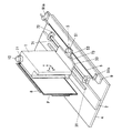
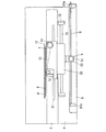
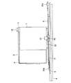
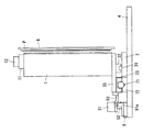
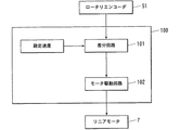
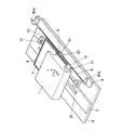
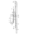
図1は、本発明の第1の実施の形態の画像読取装置における搬送機構の斜視図、図2は、図1におけるX−Z平面図、図3は、図1におけるX−Y平面図、図4は、図1におけるY−Z平面図、図5は、速度制御部を示すブロック図である。
図1〜図4に示すように、画像読取装置は、輝尽性蛍光体プレートPにレーザ光照射装置(光源)(図示しない)からのレーザ光(励起光)を走査しながら照射して輝尽性蛍光体プレートPから発せられる輝尽発光光を集光し、光電変換させて画像情報を読み取る光学ユニット1と、基台4上に設けられて光学ユニット1を水平方向に移動可能に支持する支持部材2と、光学ユニット1を移動させるリニアモータ7と、支持部材2に設けられて光学ユニット1を水平方向に案内するガイドレール31とを備えている。
また、光学ユニット1が取り付けられた移動板33に連結し、光学ユニット1とともに移動するワイヤ6及びロータリエンコーダユニット5と、光学ユニット1の移動がワイヤ6を介して伝達されて回転するプーリ52と、プーリ52の回転速度を検出するロータリエンコーダ51と、ロータリエンコーダ51の検出結果と予め設定された設定速度とを比較することによってリニアモータ7を制御する速度制御部(制御手段)100とを備えている。
以下、各構成部材について詳細に説明する。
[First Embodiment]
1 is a perspective view of a transport mechanism in an image reading apparatus according to a first embodiment of the present invention, FIG. 2 is an XZ plan view in FIG. 1, and FIG. 3 is an XY plan view in FIG. 4 is a YZ plan view of FIG. 1, and FIG. 5 is a block diagram showing a speed control unit.
As shown in FIGS. 1 to 4, the image reading apparatus irradiates the stimulable phosphor plate P while irradiating it with laser light (excitation light) from a laser light irradiation device (light source) (not shown). An
Further, the
Hereinafter, each component will be described in detail.
基台4は、略矩形板状をなしており、輝尽性蛍光体プレートPを支持する固定板8が基台4上に固定されることによって、基台4の上面に対して輝尽性蛍光体プレートPのレーザ光照射面が略垂直となるように、輝尽性蛍光体プレートPは基台4上に保持されている。
また、この輝尽性蛍光体プレートPに対向して光学ユニット1が配置されており、光学ユニット1は、下面に取り付けられた移動板33が基台4に対して移動可能に設けられ、これによって光学ユニット1は基台4に対して移動可能とされている。
The
Further, the
基台4上面の略中央には、水平方向に延在する長尺な板状の支持部材2が略水平となるように固定されている。支持部材2の上面には、光学ユニット1を水平方向に案内するガイドレール31が設けられている。
ガイドレール31は断面視略矩形状の棒状部材であって、図4に示すように、ガイドレール31に案内される断面視略コ字型状の被ガイド部材32が係合している。そして、被ガイド部材32は移動板33の下面に取り付けられている。
このように、光学ユニット1は、支持部材2、ガイドレール31、被ガイド部材32、移動板33等によって基台4上に支持されており、輝尽性蛍光体プレートPに対向して配置されている。
A long plate-
The
As described above, the
また、基台4上面で、支持部材2の側方には、リニアモータ7を構成するマグネット部71を保持するためのリニアモータ保持部72が設けられている。マグネット部71は、断面円形状の永久磁石のN極同士あるいはS極同士を複数連結してシャフト状に形成されている。
また、マグネット部71には、リニアモータ7を構成する可動コイル73が設けられている。可動コイル73は円筒状に形成されたコイルを有しており、コイルは箱状のカバー部材により覆われている。そして、可動コイル73が移動板33の下面に設けられており、リニアモータ7は可動コイル73の中心をマグネット部71が貫通するように構成されている。
Further, on the upper surface of the
Further, the
さらに、基台4上面で、リニアモータ保持部72の側方には、支持部材2と平行して水平方向に延在する長尺な板状の保持部材9が略水平となるように固定されている。保持部材9の上面の長手方向両端部には、図1に示すように、断面視略L字型の固定部材91a、91bがそれぞれ設けられており、これら固定部材91a、91bにワイヤ6の両端部が異なる高さとなるように固定され、ワイヤ6にロータリエンコーダユニット5が連結されている。図1中、ワイヤ6の右側端部は、左側端部よりも高くなるように、固定部材91aに固定されている。これによって後述するように、プーリ52に巻き付けられたワイヤ6同士が互いに接することにより擦れが発生することなく、ワイヤ6をプーリ52に1回転以上傾斜させて巻き付けることができる。
Further, on the upper surface of the
ロータリエンコーダユニット5は、移動板33に固定されて移動板33とともに移動可能な支持台53と、支持台53上に設けられたロータリエンコーダ51と、ロータリエンコーダ51の回転軸(図示しない)に連結されて支持台53の下面に取り付けられたプーリ52とを備えている。このようにロータリエンコーダ51の回転軸とプーリ52とは一体的な形状をなしている。つまり、ロータリエンコーダ51の回転軸とプーリ52の回転軸とが同じ軸となる。このように一体的な形状とすることにより、回転による偏芯を抑制することができ、ロータリエンコーダ51をより等速に回転させることが可能となる。
The
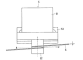
図6は、プーリ52にワイヤ6が巻き付けられた状態を示す正面図である。固定部材91a、91bに、両端部の高さが異なるように固定されたワイヤ6が、プーリ52の回転軸に直交する直交線Aに対して所定角度θとなるように傾斜した状態でプーリ52の軸回りに1回転以上巻き付けられている(図面では1回転巻き付けている)。ここで、所定角度θは、直交線Aに対して下記式(1)の関係を満たすことが好ましい。
θ≧tan-1(2r/2πR) …式(1)
r:ワイヤの半径、R:プーリの半径
このような関係でプーリ52にワイヤ6を巻き付けることにより、プーリ52上でワイヤ6同士が接触することがなく、ワイヤ6同士の擦れの発生を防止することができる。
また、ワイヤ6は、所定の張力となるように固定部材91a、91bによって調整されている。
プーリ52の材質としては、鉄材又はステンレス材が好ましく、ワイヤ6の材質としてはプーリ52の材質の表面硬度以下の材料を使用することが好ましく、例えばステンレス材上にナイロン等の樹脂をコーティングしたものを使用することが好ましい。このように
プーリ52の材質の表面硬度をワイヤ6の材質の表面硬度以上とすることにより、プーリ52の摩耗を抑制することができ、プーリ52自身の耐久性を向上させることができるとともに摩耗による等速回転の悪化を抑制することができる。
FIG. 6 is a front view showing a state where the
θ ≧ tan −1 (2r / 2πR) (1)
r: Radius of wire, R: Radius of pulley By winding the
Further, the
The material of the
このようにプーリ52に巻き付けられたワイヤ6は、光学ユニット1及び移動板33の移動に連動して水平方向に移動するようになっている。そして、ワイヤ6の移動により回転するプーリ52及びロータリエンコーダ51の回転軸から、ロータリエンコーダ51はその回転速度を検出する。そして、検出された回転速度情報は、リニアモータ7の回転速度を制御する速度制御部100に出力されるようになっている。
Thus, the
速度制御部100は、図5に示すように、差分回路101、モータ駆動制御回路102を備えている。差分回路101には、輝尽性蛍光体プレートPの水平方向に沿った移動速度に対応する上述の回転速度情報が入力される。そして、差分回路101は、この回転速度情報を処理して回転速度信号として出力し、予め設定された設定速度から得た設定速度信号と比較して差分信号を生成する。これをモータ駆動回路102に制御信号として出力する。モータ駆動回路102は差分信号に基づいてリニアモータ7を制御する。
The
一方、光学ユニット1は、レーザ光L1を輝尽性蛍光体プレートPの移動方向と直交する方向に走査させながら輝尽性蛍光体プレートPに対して照射するレーザ光照射装置と、レーザ光照射装置により輝尽性蛍光体プレートPにレーザ光L1が照射されることで励起された輝尽発光光L2を導く導光板13と、導光板13により導かれた輝尽発光光L2を集光する集光管11と、集光管11により集光された輝尽発光光L2を電気信号に変換する光電変換器12とを有している。
On the other hand, the
なお、本発明の画像読取装置には、図示しないが光学ユニット1により放射線エネルギーの読取処理がなされた後、輝尽性蛍光体プレートPに残留する放射線エネルギーを放出させるために輝尽性蛍光体プレートPに対して消去光を照射する消去装置が設けられている。
In the image reading apparatus of the present invention, although not shown, the photostimulable phosphor is used to release the radiation energy remaining in the photostimulable phosphor plate P after the radiation energy is read by the
次に、上述の構成からなる画像読取装置の動作について説明する。
搬送手段によって輝尽性蛍光体プレートPが画像読取装置の内部に取り込まれて、固定板8に固定される。画像の読取処理を行う際には、まず、リニアモータ7を駆動させて、光学ユニット1を支持する移動板33をガイドレール31に沿って水平方向に移動させる。
これにより、光学ユニット1が輝尽性蛍光体プレートPのレーザ照射面に対向する位置まで移動され、輝尽性蛍光体プレートPの水平方向に沿って移動しながら、レーザ光照射装置からレーザ光が走査される。このときレーザ光は光学ユニット1の移動方向と直交する方向に走査させながら照射される。その結果、励起された輝尽発光光が導光板13により導かれて集光管11に集光され、光電変換器12によって電気信号に変換される。
このように光学ユニット1が水平方向に移動することによって、移動板33に設けられたロータリエンコーダユニット5の支持台53を介してワイヤ6にその移動が伝達されて、プーリ52及びロータリエンコーダ51の回転軸が回転する。この際に、プーリ52にワイヤ6が、上記式(1)の条件で1回転以上巻き付けられているので、ワイヤ6がプーリ52上で接触することがなく、プーリ6を安定して定速に回転させることができる。これに伴って回転軸に連結されたロータリエンコーダ51でその回転速度が検出され、その検出結果は速度制御部100に出力される。
Next, the operation of the image reading apparatus configured as described above will be described.
The photostimulable phosphor plate P is taken into the image reading apparatus by the conveying means and fixed to the fixed
Thereby, the
As the
ロータリエンコーダ51によって検出された回転速度は、差分回路101にて予め設定された設定速度から得られた設定速度信号と比較され、その結果に応じてモータ駆動回路102がリニアモータ7の駆動を制御する。
The rotation speed detected by the
なお、リニアモータ7の駆動方法は、周知の駆動方法が用いられる。例えば、インバータ制御により交流の駆動電流の周波数と電圧とを変更することによりリニアモータ7の移動速度を制御することができる。また、PWM制御により、リニアモータ7の可動コイル73に入力するパルス電圧のパルス幅によって制御するものとしても良い。また、ステッピングモータならば、リニアモータ7に入力するパルスの周期を設定することで移動速度を制御することができる。
このようにロータリエンコーダ51の回転速度を常に検出し、その検出結果に基づいてリニアモータ7の移動速度を制御することによって、輝尽性蛍光体プレートPの移動速度を一定に保つことができる。よって、輝尽性蛍光体プレートPに蓄積された放射線エネルギーを均一に励起して、画像ムラの無い、良好な画像を得ることができる。
A known driving method is used as the driving method of the
Thus, by always detecting the rotational speed of the
輝尽性蛍光体プレートPの一方の端部まで光学ユニット1による読取処理が完了すると、リニアモータ7を停止させる。
その後、図示しない消去装置によって、輝尽性蛍光体プレートPに対して消去光を照射させ、これにより輝尽性蛍光体プレートPに残存する放射線画像を消去させる。そして、さらに搬送手段によって輝尽性蛍光体プレートPを画像読取装置の外部へと搬送させる。
When the reading process by the
Thereafter, the photostimulable phosphor plate P is irradiated with erase light by an eraser (not shown), thereby erasing the radiation image remaining on the photostimulable phosphor plate P. Further, the stimulable phosphor plate P is transported to the outside of the image reading device by the transporting means.
なお、長時間、装置が可動していない場合には、ワイヤ6がプーリ52に巻かれているため、プーリ52に沿うように巻き癖が発生する場合があるので、ワイヤ6の巻き癖を無くすため、読み取り動作を開始する前に、移動動作をさせることが好ましい。
In addition, when the apparatus is not movable for a long time, since the
以上、本発明の第1の実施の形態の画像読取装置によれば、ワイヤ6は、プーリ52の回転軸に直交する直交線Aに対して、所定角度θとなるように傾斜させて1回転以上巻き付けられているので、ワイヤ6同士の擦れが発生することがなく、プーリ52への負荷変動を抑制することができるので、プーリ52をより等速に回転させることができる。その結果、光学ユニット1を等速度で移動させて等速性を向上させることができ、輝尽性蛍光体プレートPを励起光で走査する場合に、画像ムラのない良好な画像を得ることができる。
また、ワイヤ6同士の擦れが発生しないことから、ワイヤ6自身の耐久性も向上させることができる。
As described above, according to the image reading apparatus of the first embodiment of the present invention, the
Moreover, since the friction between the
[第2の実施の形態]
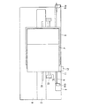
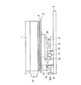
図7は、本発明の第2の実施の形態の画像読取装置における搬送機構の斜視図、図8は、図7におけるX−Z平面図、図9は、図7におけるX−Y平面図、図10は、図7におけるY−Z平面図である。
本発明の第2の実施の形態の画像読取装置は、第1の実施の形態と異なり、光学ユニット1が基台4に固定され、輝尽性蛍光体プレートPが水平方向に移動するように構成されている。
すなわち、図7〜図10に示すように、基台4の上面に対向して光学ユニット1が配置され、基台4と光学ユニット1との間に輝尽性蛍光体プレートPが配置されている。輝尽性蛍光体プレートPは、その下面に取り付けられた固定板8が、基台4に対して移動可能な移動板33に取り付けられており、これによって光学ユニット1は基台4に対して移動可能とされている。
[Second Embodiment]
7 is a perspective view of a conveyance mechanism in the image reading apparatus according to the second embodiment of the present invention, FIG. 8 is an XZ plan view in FIG. 7, and FIG. 9 is an XY plan view in FIG. 10 is a YZ plan view of FIG.
Unlike the first embodiment, the image reading apparatus of the second embodiment of the present invention is such that the
That is, as shown in FIGS. 7 to 10, the
なお、以下に説明する第1の実施の形態と同様の構成部分については、同様の符号を付すこととする。
基台4の上面の略中央に、支持部材2、支持部材2上にガイドレール31が設けられている。また、ガイドレール31には被ガイド部材32が係合し、被ガイド部材32は移動板33の下面に取り付けられている。
このように、輝尽性蛍光体プレートPは、支持部材2、ガイドレール31、被ガイド部材32、移動板33等によって基台4上に支持されており、光学ユニット1に対向して配置されている。
Components similar to those in the first embodiment described below are denoted by the same reference numerals.
A
As described above, the photostimulable phosphor plate P is supported on the
また、基台4上面には、第1の実施の形態と同様のリニアモータ7、リニアモータ保持部72、マグネット部71、可動コイル73が設けられ、さらに、保持部材9、固定部材91a、91bが設けられている。そして、固定部材91a、91bにワイヤ6の両端部が高さが異なるように固定され、ワイヤ6にロータリエンコーダユニット5が連結されている。
The top surface of the
ロータリエンコーダユニット5も、第1の実施の形態と同様に、移動板33に固定されて移動可能な支持台53と、ロータリエンコーダ51と、プーリ52とを備えており、ロータリエンコーダ51の回転軸とプーリ52とが一体的な形状をなしている。
また、ワイヤ6はプーリ52の回転軸に直交する直交線Aに対して所定角度θとなるように傾斜した状態でプーリ52の軸回りに1回転以上巻きつけられ、所定角度θが上記式(1)の関係とされている。
Similarly to the first embodiment, the
Further, the
その他、第2の実施の形態においても第1の実施の形態と同様の速度制御部100を備え、また、光学ユニット1も第1の実施の形態と同様の機能を有する。
In addition, the second embodiment also includes a
次に、上述の構成からなる画像読取装置の動作について説明する。
搬送手段によって輝尽性蛍光体プレートPが画像読取装置の内部に取り込まれて、固定板8に固定される。画像の読取処理を行う際には、まず、リニアモータ7を駆動させて、輝尽性蛍光体プレートPを支持する移動板33をガイドレール31に沿って水平方向に移動させる。
これにより、輝尽性蛍光体プレートPが光学ユニット1のレーザ照射面に対向する位置まで移動され、光学ユニット1の水平方向に沿って移動しながら、レーザ光照射装置からレーザ光が走査される。このときレーザ光は光学ユニット1の移動方向と直交する方向に走査させながら照射される。その結果、励起された輝尽発光光が導光板13により導かれて集光管11に集光され、光電変換器12によって電気信号に変換される。
このように輝尽性蛍光体プレートPが水平方向に移動することによって、移動板33に設けられたロータリエンコーダユニット5の支持台53を介してワイヤ6にその移動が伝達されて、プーリ52及びロータリエンコーダ51の回転軸が回転する。この際に、プーリ52にワイヤ6が、上記式(1)の条件で1回転以上巻き付けられているので、ワイヤ6がプーリ52上で接触することがなく、プーリ52を安定して定速に回転させることができる。これに伴って回転軸に連結されたロータリエンコーダ51でその回転速度が検出され、その検出結果は速度制御部100に出力される。
Next, the operation of the image reading apparatus configured as described above will be described.
The photostimulable phosphor plate P is taken into the image reading apparatus by the conveying means and fixed to the fixed
Thereby, the photostimulable phosphor plate P is moved to a position facing the laser irradiation surface of the
As the photostimulable phosphor plate P moves in the horizontal direction in this way, the movement is transmitted to the
ロータリエンコーダ51によって検出された回転速度は、差分回路101にて予め設定された設定速度から得られた設定速度信号と比較され、その結果に応じてモータ駆動回路102がリニアモータ7の駆動を制御する。
このようにロータリエンコーダ5の回転速度を常に検出し、その検出結果に基づいてリニアモータ7の移動速度を制御することによって、輝尽性蛍光体プレートPの移動速度を一定に保つことができる。よって、輝尽性蛍光体プレートPに蓄積された放射線エネルギーを均一に励起して、画像ムラの無い、良好な画像を得ることができる。
The rotation speed detected by the
Thus, by always detecting the rotational speed of the
輝尽性蛍光体プレートPの一方の端部まで光学ユニット1による読取処理が完了すると、リニアモータ7を停止させ、その後、図示しない消去装置によって、輝尽性蛍光体プレートPに対して消去光を照射させ、輝尽性蛍光体プレートPに残存する放射線画像を消去させる。そして、さらに搬送手段によって輝尽性蛍光体プレートPを画像読取装置の外部へと搬送させる。
When the reading process by the
また、本発明の第2の実施の形態においても、長時間、装置が可動していない場合には、プーリ52に巻き付けられたワイヤ6の巻き癖を無くすため、読み取り動作を開始する前に、移動動作をさせることが好ましい。
Also in the second embodiment of the present invention, when the apparatus has not been moved for a long time, before starting the reading operation, the
以上、本発明の第2の実施の形態の画像読取装置によれば、ワイヤ6は、プーリ52の回転軸に直交する直交線Aに対して、所定角度θとなるように傾斜させて1回転以上巻き付けられているので、ワイヤ6同士の擦れが発生することがなく、プーリ52への負荷変動を抑制することができるので、プーリ52をより等速に回転させることができる。その結果、輝尽性蛍光体プレートPを等速度で移動させて等速性を向上させることができ、輝尽性蛍光体プレートPを励起光で走査する場合に、画像ムラのない良好な画像を得ることができる。
また、ワイヤ6同士の擦れが発生しないことから、ワイヤ6自身の耐久性も向上させることができる。
As described above, according to the image reading apparatus of the second embodiment of the present invention, the
Moreover, since the friction between the
なお、本発明の実施の形態は、上記実施の形態に限定されるものではなく、その要旨を変更しない限り適宜変更可能である。
例えば、ガイドレール31は断面視略矩形状の棒状部材であるとしたが、断面視略円形状等としても良い。
また、本実施の形態では、プーリ52にワイヤ6を1回転しか巻き付けていないが、複数回巻き付けるようにしても良い。この場合、固定部材91a、91bに固定するワイヤ6の両端部の高さを、さらに変えることが好ましい。
さらに、本実施の形態で使用するワイヤ6の材料としては、例えばスチールワイヤ等が挙げられるが、特に限定されるものではない。
In addition, embodiment of this invention is not limited to the said embodiment, It can change suitably, unless the summary is changed.
For example, the
Further, in the present embodiment, the
Furthermore, examples of the material of the
1 光学ユニット
6 ワイヤ
7 リニアモータ
51 ロータリエンコーダ
52 プーリ
100 速度制御部(制御手段)
P 輝尽性蛍光体プレート
A 直交線
DESCRIPTION OF
P photostimulable phosphor plate A orthogonal line
Claims (6)
前記輝尽性蛍光体プレートに光源からの励起光を走査させながら照射して前記輝尽性蛍光体プレートから発せられる輝尽発光光を集光し光電変換させて画像情報を読み取る光学ユニットと、
前記光学ユニットを移動するリニアモータと、
前記光学ユニットの移動に伴い、ワイヤを介して回転せしめられるプーリと、
前記プーリの回転速度を検出するロータリエンコーダと、
前記ロータリエンコーダの検出結果から前記リニアモータを制御する制御手段とを備え、
前記ワイヤは、前記プーリの回転軸に直交する直交線に対して、所定角度となるように傾斜させて、前記プーリの軸回りに1回転以上巻き付けられていることを特徴とする画像読取装置。 In the image reading apparatus that reads the image information by irradiating the stimulable phosphor plate with the stimulable phosphor sheet with excitation light,
An optical unit that reads the image information by condensing and photoelectrically converting the photostimulated luminescence emitted from the photostimulable phosphor plate by irradiating the photostimulable phosphor plate while scanning with excitation light from a light source;
A linear motor that moves the optical unit;
As the optical unit moves, a pulley that is rotated through a wire;
A rotary encoder for detecting the rotational speed of the pulley;
Control means for controlling the linear motor from the detection result of the rotary encoder,
The image reading apparatus according to claim 1, wherein the wire is wound at least once around the axis of the pulley so as to be inclined at a predetermined angle with respect to an orthogonal line orthogonal to the rotation axis of the pulley.
前記輝尽性蛍光体プレートに光源からの励起光を走査させながら照射して前記輝尽性蛍光体プレートから発せられる輝尽発光光を集光し光電変換させて画像情報を読み取る光学ユニットと、
前記輝尽性蛍光体プレートを移動するリニアモータと、
前記輝尽性蛍光体プレートとともに移動するワイヤと、
前記輝尽性蛍光体プレートの移動がワイヤを介して伝達されることによって回転するプーリと、
前記プーリの回転速度を検出するロータリエンコーダと、
前記ロータリエンコーダの検出結果から前記リニアモータを制御する制御手段とを備え、
前記ワイヤは、前記プーリの回転軸に直交する直交線に対して、所定角度となるように傾斜させて、前記プーリの軸回りに1回転以上巻き付けられていることを特徴とする画像読取装置。 In the image reading apparatus that reads the image information by irradiating the stimulable phosphor plate with the stimulable phosphor sheet with excitation light,
An optical unit that reads the image information by condensing and photoelectrically converting the photostimulated luminescence emitted from the photostimulable phosphor plate by irradiating the photostimulable phosphor plate while scanning with excitation light from a light source;
A linear motor for moving the photostimulable phosphor plate;
A wire that moves with the photostimulable phosphor plate;
A pulley rotated by being transmitted via a mobile side ear of the stimulable phosphor plate,
A rotary encoder for detecting the rotational speed of the pulley;
Control means for controlling the linear motor from the detection result of the rotary encoder,
The image reading apparatus according to claim 1, wherein the wire is wound at least once around the axis of the pulley so as to be inclined at a predetermined angle with respect to an orthogonal line orthogonal to the rotation axis of the pulley.
θ≧tan-1(2r/2πR)
r:ワイヤの半径、R:プーリの半径 3. The image reading apparatus according to claim 1, wherein when the predetermined angle is θ, the wire is wound around the axis of the pulley according to the following formula.
θ ≧ tan -1 (2r / 2πR)
r: radius of wire, R: radius of pulley
Priority Applications (4)
| Application Number | Priority Date | Filing Date | Title |
|---|---|---|---|
| JP2005129481A JP4241663B2 (en) | 2005-04-27 | 2005-04-27 | Image reading device |
| US11/912,472 US20090078893A1 (en) | 2005-04-27 | 2006-04-14 | Image reading apparatus |
| CNA2006800136912A CN101164012A (en) | 2005-04-27 | 2006-04-14 | image reading device |
| PCT/JP2006/307900 WO2006118000A1 (en) | 2005-04-27 | 2006-04-14 | Image scanner |
Applications Claiming Priority (1)
| Application Number | Priority Date | Filing Date | Title |
|---|---|---|---|
| JP2005129481A JP4241663B2 (en) | 2005-04-27 | 2005-04-27 | Image reading device |
Publications (2)
| Publication Number | Publication Date |
|---|---|
| JP2006308752A JP2006308752A (en) | 2006-11-09 |
| JP4241663B2 true JP4241663B2 (en) | 2009-03-18 |
Family
ID=37475734
Family Applications (1)
| Application Number | Title | Priority Date | Filing Date |
|---|---|---|---|
| JP2005129481A Expired - Fee Related JP4241663B2 (en) | 2005-04-27 | 2005-04-27 | Image reading device |
Country Status (2)
| Country | Link |
|---|---|
| JP (1) | JP4241663B2 (en) |
| CN (1) | CN101164012A (en) |
Families Citing this family (2)
| Publication number | Priority date | Publication date | Assignee | Title |
|---|---|---|---|---|
| CN106907447A (en) * | 2017-04-13 | 2017-06-30 | 三峡大学 | Convert rotational motion is the device of straight reciprocating motion |
| JP6978124B2 (en) * | 2018-03-31 | 2021-12-08 | つくばテクノロジー株式会社 | X-ray inspection device for drones, X-ray inspection device using drones, X-ray generator for drones |
-
2005
- 2005-04-27 JP JP2005129481A patent/JP4241663B2/en not_active Expired - Fee Related
-
2006
- 2006-04-14 CN CNA2006800136912A patent/CN101164012A/en active Pending
Also Published As
| Publication number | Publication date |
|---|---|
| JP2006308752A (en) | 2006-11-09 |
| CN101164012A (en) | 2008-04-16 |
Similar Documents
| Publication | Publication Date | Title |
|---|---|---|
| JP4241663B2 (en) | Image reading device | |
| JPWO2006043425A1 (en) | Image reading device | |
| JP2007017870A (en) | Image reader and image forming apparatus | |
| US7391044B2 (en) | Movable-component linear drive apparatus | |
| JP2007017869A (en) | Image scanner and image forming apparatus | |
| JP2006141141A (en) | Transport device, image scanner, and image forming apparatus | |
| JP2007020083A (en) | Image reader, image forming device and conveyance control method | |
| JP2007193171A (en) | Image reader and image reading method | |
| JP2007279074A (en) | Image reader and conveying apparatus | |
| JP2006113169A (en) | Image scanner | |
| US20090078893A1 (en) | Image reading apparatus | |
| JP2003248276A (en) | Laser light scanner and image reader | |
| JP2006136051A (en) | Linear motor | |
| JP4342994B2 (en) | Radiation image recording / reading apparatus and radiation image recording cassette | |
| JP5391136B2 (en) | Radiation image reading apparatus and image recording body | |
| JP2004212523A (en) | Radiography reader | |
| JP2005073042A (en) | Image reader and image recorder | |
| JP2004212524A (en) | Radiography reader | |
| JP2005070533A (en) | Moving device, image reader, and image forming device | |
| JP2008122487A (en) | Image reading apparatus | |
| JP4281951B2 (en) | Optical scanning method and apparatus | |
| JP2005073023A (en) | Image reading apparatus and image forming apparatus | |
| JP5921511B2 (en) | Radiation image reading apparatus, radiation image reading program, and radiation image reading method | |
| JP2006038975A (en) | Medical x-ray radiographic apparatus | |
| JP2004258304A (en) | Image reader |
Legal Events
| Date | Code | Title | Description |
|---|---|---|---|
| A131 | Notification of reasons for refusal |
Free format text: JAPANESE INTERMEDIATE CODE: A131 Effective date: 20080722 |
|
| A521 | Written amendment |
Free format text: JAPANESE INTERMEDIATE CODE: A523 Effective date: 20080908 |
|
| TRDD | Decision of grant or rejection written | ||
| A01 | Written decision to grant a patent or to grant a registration (utility model) |
Free format text: JAPANESE INTERMEDIATE CODE: A01 Effective date: 20081209 |
|
| A01 | Written decision to grant a patent or to grant a registration (utility model) |
Free format text: JAPANESE INTERMEDIATE CODE: A01 |
|
| A61 | First payment of annual fees (during grant procedure) |
Free format text: JAPANESE INTERMEDIATE CODE: A61 Effective date: 20081222 |
|
| FPAY | Renewal fee payment (event date is renewal date of database) |
Free format text: PAYMENT UNTIL: 20120109 Year of fee payment: 3 |
|
| R150 | Certificate of patent or registration of utility model |
Free format text: JAPANESE INTERMEDIATE CODE: R150 |
|
| LAPS | Cancellation because of no payment of annual fees |