JP2005073023A - Image reading apparatus and image forming apparatus - Google Patents
Image reading apparatus and image forming apparatus Download PDFInfo
- Publication number
- JP2005073023A JP2005073023A JP2003301077A JP2003301077A JP2005073023A JP 2005073023 A JP2005073023 A JP 2005073023A JP 2003301077 A JP2003301077 A JP 2003301077A JP 2003301077 A JP2003301077 A JP 2003301077A JP 2005073023 A JP2005073023 A JP 2005073023A
- Authority
- JP
- Japan
- Prior art keywords
- image
- moving
- moving body
- linear motor
- recording medium
- Prior art date
- Legal status (The legal status is an assumption and is not a legal conclusion. Google has not performed a legal analysis and makes no representation as to the accuracy of the status listed.)
- Pending
Links
Images


Landscapes
- Image Input (AREA)
- Facsimiles In General (AREA)
- Facsimile Scanning Arrangements (AREA)
Abstract
Description
本発明は、画像読取装置及び画像形成装置に係り、特に、画像読取処理あるいは画像形成処理における主走査又は副走査の駆動源としてリニアモータを用いた画像読取装置及び画像形成装置に関する。 The present invention relates to an image reading apparatus and an image forming apparatus, and more particularly to an image reading apparatus and an image forming apparatus using a linear motor as a driving source for main scanning or sub scanning in image reading processing or image forming processing.
一般に様々な分野において、例えば、画像が記録された記録媒体に対してレーザ光を主走査方向に走査させながら記録媒体を主走査方向と直交する副走査方向に搬送させることにより画像を読み取る画像読取装置や、例えば、所定の画像データに基づいてレーザ光照射装置を記録媒体に対して主走査方向に走査させながら記録媒体を主走査方向と直交する副走査方向に搬送させることにより画像を形成する画像形成装置が用いられている。 In general, in various fields, for example, image reading for reading an image by transporting the recording medium in a sub-scanning direction orthogonal to the main scanning direction while scanning a laser beam in the main scanning direction with respect to the recording medium on which the image is recorded. An image is formed by conveying the recording medium in a sub-scanning direction orthogonal to the main scanning direction while the apparatus or, for example, a laser beam irradiation device scans the recording medium in the main scanning direction based on predetermined image data. An image forming apparatus is used.
特に、医療の分野においては、放射線画像が病気診断等に広く用いられており、この放射線画像を得るための方式として、被写体を透過させた放射線を輝尽性蛍光体シートに蓄積、記録させた後、画像読取装置により励起光を照射することによって蓄積、記録された放射線エネルギーを輝尽発光させ、この輝尽発光光の強弱を電気信号に変換し、この電気信号に基づいて画像形成装置により可視画像を記録媒体に形成させることが行われている。 In particular, in the medical field, radiographic images are widely used for disease diagnosis and the like. As a method for obtaining such radiographic images, radiation transmitted through a subject is accumulated and recorded in a stimulable phosphor sheet. After that, the radiation energy stored and recorded by irradiating the excitation light with the image reading device is stimulated to emit light, the intensity of this stimulated emission light is converted into an electric signal, and the image forming device is based on this electric signal. A visible image is formed on a recording medium.
このように医療の分野で用いられる画像読取装置及び画像形成装置においては、特に、得られた画像に基づいて病気の診断等を行う観点から、高精細な画像を得られることが要請される。高精細な画像を得るためには、記録媒体やレーザ光照射装置等の走査を正確かつ滑らかに行う必要があり、このため、近年、記録媒体やレーザ光照射装置等の直進移動の駆動源としてリニアモータを用いることが提案されている。 As described above, the image reading apparatus and the image forming apparatus used in the medical field are required to obtain a high-definition image particularly from the viewpoint of diagnosing a disease based on the obtained image. In order to obtain a high-definition image, it is necessary to scan the recording medium and the laser beam irradiation device accurately and smoothly. For this reason, as a drive source for linear movement of the recording medium and the laser beam irradiation device in recent years, It has been proposed to use a linear motor.
レーザ光照射装置の走査の駆動源としてリニアモータを用いた画像形成装置として、記録媒体を支持して回動可能な円筒状の支持ドラムと、この支持ドラムに対向して設けられ、記録媒体の幅方向に往復移動しながら所定の画像データに基づいてレーザ光を照射するレーザ光照射装置とを有し、このレーザ光照射装置を移動させるリニアモータを設けた画像形成装置が知られている(例えば特許文献1参照)。 As an image forming apparatus using a linear motor as a scanning drive source of a laser beam irradiation apparatus, a cylindrical support drum that supports and rotates a recording medium, and is provided to face the support drum. 2. Description of the Related Art An image forming apparatus that includes a laser light irradiation device that irradiates laser light based on predetermined image data while reciprocating in the width direction and includes a linear motor that moves the laser light irradiation device is known ( For example, see Patent Document 1).
この画像形成装置は、レーザ光照射装置を保持する保持部を有しており、この保持部の下方には、リニアモータを構成する断面コ字形状のマグネット部が、一側方に開口するとともに、記録媒体の搬送方向と直交する方向に延在して設けられている。また、保持部の下面には、リニアモータを構成し保持部の下面から垂下するとともに水平方向に延在する断面L字形状の可動コイルが、水平部の上下両面をマグネット部の開口部に挟まれるように設けられている。これにより、レーザ光照射装置が、保持部のリニアモータによる往復移動に伴って移動しながら、記録媒体に対してレーザ光を走査させるようになっている。
しかしながら、上記のような画像形成装置では、可動コイルの水平部及び垂直部の剛性が十分でない場合には、リニアモータの搬送速度に対して保持部に遅れが生じたり、振動が発生して滑らかな搬送ができず、その結果、保持部に保持されたレーザ光照射装置による記録媒体に対するレーザ光の照射に位置ずれが生じて、画像むらが発生する場合がある。したがって、良好な画像を得るためには、可動コイルの剛性を高める必要があり、この結果、可動コイルは一定以上の大きさを要し、装置の小型化及び低コスト化に限界があるという問題があった。 However, in the image forming apparatus as described above, when the horizontal portion and the vertical portion of the movable coil are not sufficiently rigid, the holding portion is delayed from the conveyance speed of the linear motor, or vibration is generated, resulting in smoothness. As a result, the laser beam irradiation apparatus holding the holding unit may shift the position of the laser beam applied to the recording medium, resulting in image unevenness. Therefore, in order to obtain a good image, it is necessary to increase the rigidity of the moving coil. As a result, the moving coil requires a certain size or more, and there is a limit to downsizing and cost reduction of the apparatus. was there.
また、マグネット部がコ字形状のリニアモータでは、磁束の利用効率が悪く、大きい推力を得たい場合には、磁束密度を大きくしなければならず、その結果、マグネット部の大きさが大きくなることからも、装置の小型化及び低コスト化に限界があった。 In addition, in a linear motor having a U-shaped magnet, the use efficiency of the magnetic flux is poor, and in order to obtain a large thrust, the magnetic flux density must be increased, resulting in an increase in the size of the magnet. For this reason, there was a limit to miniaturization and cost reduction of the apparatus.
そこで、本発明は、小型で低コストな装置構成により、高精細な画像を得ることができる画像読取装置及び画像形成装置を提供することを目的とする。 SUMMARY An advantage of some aspects of the invention is that it provides an image reading apparatus and an image forming apparatus that can obtain a high-definition image with a small and low-cost apparatus configuration.
上記課題を解決するために本発明による画像読取装置は、画像が記録された記録媒体及び前記記録媒体に記録された画像を読み取る読取部のいずれか一方からなる移動対象物を他方に対して移動させて画像を読み取る画像読取装置において、マグネット部と可動コイルとにより構成され前記移動対象物を直進移動させるリニアモータを設け、前記マグネット部を移動方向に延在するシャフト状に形成したことを特徴とする。 In order to solve the above-described problems, an image reading apparatus according to the present invention moves a moving object composed of one of a recording medium on which an image is recorded and a reading unit that reads the image recorded on the recording medium with respect to the other. In the image reading apparatus for reading an image, a linear motor configured by a magnet part and a movable coil is provided to linearly move the moving object, and the magnet part is formed in a shaft shape extending in the moving direction. And
請求項1に記載の発明によれば、マグネット部がシャフト状であるため、可動コイルでシャフト状のマグネット部の周面を覆うようにすればよく、可動コイルが剛性の得やすい形状となる。そのため、可動コイルを必要以上に大きくすることなく、リニアモータの搬送速度に対して移動速度の遅れを生じさせることを防止できる上、振動を発生させることなく記録媒体又は読取部が滑らかに搬送される。 According to the first aspect of the present invention, since the magnet portion is in the shape of a shaft, it is only necessary to cover the peripheral surface of the shaft-shaped magnet portion with the movable coil, and the movable coil has a shape that is easy to obtain rigidity. For this reason, it is possible to prevent the movement speed from being delayed with respect to the conveyance speed of the linear motor without enlarging the movable coil more than necessary, and the recording medium or the reading unit can be smoothly conveyed without generating vibration. The
また、シャフト状のマグネット部の周面を可動コイルで覆うようにすれば、磁束の利用効率が良く、大きい推力を得たい場合にも、マグネット部の大きさを必要以上に大きくせずにすむ。 In addition, if the peripheral surface of the shaft-shaped magnet part is covered with a movable coil, the magnetic flux can be used efficiently, and even when it is desired to obtain a large thrust, it is not necessary to increase the size of the magnet part more than necessary. .
また、請求項2に記載の発明は、請求項1に記載の画像読取装置において、前記移動対象物の直進移動をガイドするガイド部を設けたことを特徴とする。 According to a second aspect of the present invention, in the image reading apparatus according to the first aspect of the present invention, a guide portion that guides the straight movement of the moving object is provided.
請求項2に記載の発明によれば、移動対象物の直進移動をガイドするガイド部が設けられているため、移動対象物である記録媒体又は読取部が安定して搬送される。 According to the second aspect of the present invention, since the guide unit that guides the straight movement of the moving object is provided, the recording medium or the reading unit that is the moving object is stably conveyed.
また、請求項3に記載の発明は、請求項2に記載の画像読取装置において、前記ガイド部は単数であることを特徴とする。 According to a third aspect of the present invention, in the image reading apparatus according to the second aspect, the guide section is single.
請求項3に記載の発明によれば、より装置全体の小型化及び低コスト化を図ることができる。
According to the invention described in
また、請求項4に記載の発明は、請求項1から3のいずれか一項に記載の画像読取装置において、前記移動方向は鉛直方向であることを特徴とする。 According to a fourth aspect of the present invention, in the image reading apparatus according to any one of the first to third aspects, the moving direction is a vertical direction.
請求項4に記載の発明によれば、移動方向が鉛直方向であっても、可動コイルを必要以上に大きくすることなく、リニアモータの搬送速度に対して移動速度の遅れが生じることが防止され、振動が発生することなく、記録媒体又は読取部が滑らかに搬送される。 According to the fourth aspect of the present invention, even if the moving direction is the vertical direction, it is possible to prevent the moving speed from being delayed with respect to the linear motor conveying speed without making the movable coil larger than necessary. The recording medium or the reading unit is smoothly conveyed without vibration.
また、シャフト状のマグネット部の周面を可動コイルで覆うようにすれば、磁束の利用効率が良く、大きい推力を得たい場合にも、マグネット部の大きさを必要以上に大きくせずにすむ。 In addition, if the peripheral surface of the shaft-shaped magnet part is covered with a movable coil, the magnetic flux can be used efficiently, and even when it is desired to obtain a large thrust, it is not necessary to increase the size of the magnet part more than necessary. .
請求項5に記載の発明は、請求項4に記載の画像読取装置において、前記移動対象物を保持して移動する移動体と前記移動体と釣り合う釣合錘とを設けるとともに、前記移動体と前記釣合錘とを連結する連結部材を設け、前記移動体は前記リニアモータにより直進移動し、前記釣合錘は前記移動体と相対的に移動することを特徴とする。 According to a fifth aspect of the present invention, in the image reading device according to the fourth aspect of the present invention, a moving body that holds and moves the moving object and a counterweight that balances the moving body are provided, and the moving body A connecting member for connecting the counterweight is provided, the moving body moves linearly by the linear motor, and the counterweight moves relative to the moving body.
請求項5に記載の発明によれば、移動体をリニアモータにより上昇させる際に、釣合錘が自重落下するため、リニアモータによる推力を低減させることができる。 According to the fifth aspect of the present invention, when the moving body is raised by the linear motor, the counterweight falls by its own weight, so that the thrust by the linear motor can be reduced.
請求項6に記載の発明は、請求項5に記載の画像読取装置において、前記リニアモータの駆動停止時に、前記移動体又は前記釣合錘の自重落下を防止するブレーキ機構を備えたことを特徴とする。 A sixth aspect of the present invention is the image reading apparatus according to the fifth aspect, further comprising a brake mechanism that prevents the moving body or the counterweight from falling by its own weight when the driving of the linear motor is stopped. And
請求項6に記載の発明によれば、リニアモータの駆動が停止したときに、移動体又は釣合錘が自重により落下することを防止できる。 According to the sixth aspect of the present invention, it is possible to prevent the moving body or the counterweight from falling due to its own weight when the driving of the linear motor is stopped.
請求項7に記載の発明による画像形成装置は、記録媒体及び前記記録媒体に画像を記録する記録部のいずれか一方からなる移動対象物を他方に対して移動させて画像を形成する画像形成装置において、マグネット部と可動コイルとにより構成され前記移動対象物を直進移動させるリニアモータを設け、前記マグネット部を移動方向に延在するシャフト状に形成したことを特徴とする。 An image forming apparatus according to claim 7 forms an image by moving a moving object composed of either one of a recording medium and a recording unit for recording an image on the recording medium with respect to the other. In the present invention, a linear motor that includes a magnet portion and a movable coil and moves the moving object linearly is provided, and the magnet portion is formed in a shaft shape extending in the moving direction.
請求項7に記載の発明によれば、マグネット部がシャフト状であるため、可動コイルでシャフト状のマグネット部の周面を覆うようにすればよく、可動コイルが剛性の得やすい形状となる。そのため、可動コイルを必要以上に大きくすることなく、リニアモータの搬送速度に対して移動体に遅れを生じさせることを防止できる上、振動を発生させることなく記録媒体又は記録部が滑らかに搬送される。 According to the seventh aspect of the present invention, since the magnet portion has a shaft shape, it is only necessary to cover the peripheral surface of the shaft-shaped magnet portion with the movable coil, and the movable coil has a shape in which rigidity is easily obtained. Therefore, it is possible to prevent the moving body from being delayed with respect to the conveyance speed of the linear motor without enlarging the moving coil more than necessary, and the recording medium or the recording unit can be smoothly conveyed without generating vibration. The
また、シャフト状のマグネット部の周面を可動コイルで覆うようにすれば、磁束の利用効率が良く、大きい推力を得たい場合にも、マグネット部の大きさを必要以上に大きくせずにすむ。 In addition, if the peripheral surface of the shaft-shaped magnet part is covered with a movable coil, the magnetic flux can be used efficiently, and even when it is desired to obtain a large thrust, it is not necessary to increase the size of the magnet part more than necessary. .
請求項8に記載の発明は、請求項7に記載の画像形成装置において、前記移動対象物の直進移動をガイドするガイド部を設けたことを特徴とする。 According to an eighth aspect of the present invention, in the image forming apparatus according to the seventh aspect of the present invention, a guide portion that guides the straight movement of the moving object is provided.
請求項8に記載の発明によれば、移動対象物の直進移動をガイドするガイド部が設けられているため、移動対象物である記録媒体又は記録部が安定して搬送される。 According to the eighth aspect of the present invention, since the guide portion that guides the straight movement of the moving object is provided, the recording medium or the recording portion that is the moving object is stably conveyed.
請求項9に記載の発明は、請求項8に記載の画像形成装置において、前記ガイド部は単数であることを特徴とする。 According to a ninth aspect of the present invention, in the image forming apparatus according to the eighth aspect of the present invention, the guide section is single.
請求項9に記載の発明によれば、より装置全体の小型化及び低コスト化を図ることができる。
According to the invention described in
請求項10に記載の発明は、請求項7から9のいずれか一項に記載の画像形成装置において、前記移動方向は鉛直方向であることを特徴とする。 According to a tenth aspect of the present invention, in the image forming apparatus according to any one of the seventh to ninth aspects, the moving direction is a vertical direction.
請求項10に記載の発明によれば、移動方向が鉛直方向であっても、可動コイルを必要以上に大きくすることなく、リニアモータの搬送速度に対して移動体に遅れが生じることが防止され、振動が発生することなく、記録媒体又は記録部が滑らかに搬送される。 According to the tenth aspect of the present invention, even when the moving direction is the vertical direction, it is possible to prevent the moving body from being delayed with respect to the conveying speed of the linear motor without increasing the moving coil more than necessary. The recording medium or the recording unit is smoothly conveyed without vibration.
また、シャフト状のマグネット部の周面を可動コイルで覆うようにすれば、磁束の利用効率が良く、大きい推力を得たい場合にも、マグネット部の大きさを必要以上に大きくせずにすむ。 In addition, if the peripheral surface of the shaft-shaped magnet part is covered with a movable coil, the magnetic flux can be used efficiently, and even when it is desired to obtain a large thrust, it is not necessary to increase the size of the magnet part more than necessary. .
請求項11に記載の発明は、請求項10に記載の画像形成装置において、前記移動対象物を保持して移動する移動体と前記移動体と釣り合う釣合錘とを設けるとともに、前記移動体と前記釣合錘とを連結する連結部材を設け、前記移動体は前記リニアモータにより直進移動し、前記釣合錘は前記移動体と相対的に移動することを特徴とする。 According to an eleventh aspect of the present invention, in the image forming apparatus according to the tenth aspect of the present invention, a moving body that holds and moves the moving object and a counterweight that balances the moving body are provided. A connecting member for connecting the counterweight is provided, the moving body moves linearly by the linear motor, and the counterweight moves relative to the moving body.
請求項11に記載の発明によれば、移動体をリニアモータにより上昇させる際に、釣合錘が自重落下するため、リニアモータによる推力を低減させることができる。 According to the eleventh aspect of the present invention, since the counterweight falls by its own weight when the moving body is raised by the linear motor, the thrust by the linear motor can be reduced.
請求項12に記載の発明は、請求項11に記載の画像形成装置において、前記リニアモータの駆動停止時に、前記移動体又は前記釣合錘の自重落下を防止するブレーキ機構を備えたことを特徴とする。 According to a twelfth aspect of the present invention, in the image forming apparatus according to the eleventh aspect of the present invention, the image forming apparatus further includes a brake mechanism that prevents the movable body or the counterweight from falling by its own weight when the driving of the linear motor is stopped. And
請求項12に記載の発明によれば、リニアモータの駆動が停止したときに、移動体又は釣合錘が自重により落下することを防止できる。 According to the twelfth aspect of the present invention, it is possible to prevent the moving body or the counterweight from falling due to its own weight when the driving of the linear motor is stopped.
請求項1に記載の発明によれば、可動コイルが装置内に固定される上で剛性の得やすい形状となり、可動コイルを必要以上に大きくすることなく、リニアモータの搬送速度に対して移動速度の遅れが生じることが防止され、振動が発生することなく、記録媒体又は読取部が滑らかに搬送されるため、小型で低コストな装置構成により、高精細な画像を得ることができる。 According to the first aspect of the present invention, the movable coil is fixed in the apparatus so that rigidity is easily obtained, and the moving speed is increased with respect to the conveying speed of the linear motor without making the movable coil larger than necessary. Is prevented, and the recording medium or the reading unit is smoothly transported without generating vibration. Therefore, a high-definition image can be obtained with a small and low-cost apparatus configuration.
また、シャフト状のマグネット部の周面を可動コイルで覆うようにすれば、磁束の利用効率が良く、大きい推力を得たい場合にも、マグネット部の大きさを必要以上に大きくせずにすむことからも、装置の小型化及び低コスト化を図ることができる。 In addition, if the peripheral surface of the shaft-shaped magnet part is covered with a movable coil, the magnetic flux can be used efficiently, and even when it is desired to obtain a large thrust, it is not necessary to increase the size of the magnet part more than necessary. Therefore, it is possible to reduce the size and cost of the apparatus.
請求項2に記載の発明によれば、移動対象物をガイドするガイド部が設けられており、移動対象物である記録媒体又は読取部がより滑らかに搬送されるため、より高精細な画像を得ることができる。 According to the second aspect of the present invention, the guide unit that guides the moving object is provided, and the recording medium or the reading unit that is the moving object is more smoothly conveyed, so that a higher-definition image can be obtained. Can be obtained.
請求項3に記載の発明によれば、ガイド部は単数であるため、より装置全体の小型化及び低コスト化を図ることができる。 According to the third aspect of the present invention, since the guide portion is singular, the entire apparatus can be further reduced in size and cost.
請求項4に記載の発明によれば、移動方向が鉛直方向であっても、可動コイルを必要以上に大きくすることなく、リニアモータの搬送速度に対して移動速度の遅れが生じることが防止され、振動が発生することなく、記録媒体又は読取部が滑らかに搬送されるため、小型で低コストな装置構成により、高精細な画像を得ることができる。 According to the fourth aspect of the present invention, even if the moving direction is the vertical direction, it is possible to prevent the moving speed from being delayed with respect to the linear motor conveying speed without making the movable coil larger than necessary. Since the recording medium or the reading unit is smoothly conveyed without vibration, a high-definition image can be obtained with a small and low-cost apparatus configuration.
また、シャフト状のマグネット部の周面を可動コイルで覆うようにすれば、磁束の利用効率が良く、大きい推力を得たい場合にも、マグネット部の大きさを必要以上に大きくせずにすむことからも、装置の小型化及び低コスト化を図ることができる。 In addition, if the peripheral surface of the shaft-shaped magnet part is covered with a movable coil, the magnetic flux can be used efficiently, and even when it is desired to obtain a large thrust, it is not necessary to increase the size of the magnet part more than necessary. Therefore, it is possible to reduce the size and cost of the apparatus.
請求項5に記載の発明によれば、移動体をリニアモータにより上昇させる際に、釣合錘が自重落下することから、リニアモータによる推力を低減させることができるため、よりマグネット部及び可動コイルを小型化することができ、ひいては装置の小型化及び低コスト化を図ることができる。
According to the invention described in
請求項6に記載の発明によれば、リニアモータの駆動が停止したときに、移動体又は釣合錘が自重により落下することを防止できる。 According to the sixth aspect of the present invention, it is possible to prevent the moving body or the counterweight from falling due to its own weight when the driving of the linear motor is stopped.
請求項7に記載の発明によれば、可動コイルが装置内に固定される上で剛性の得やすい形状となり、可動コイルを必要以上に大きくすることなく、リニアモータの搬送速度に対して移動速度の遅れが生じることが防止され、振動が発生することなく、記録媒体又は記録部が滑らかに搬送されるため、小型で低コストな装置構成により、高精細な画像を得ることができる。 According to the seventh aspect of the present invention, the movable coil is fixed in the apparatus so that it is easy to obtain rigidity, and the moving speed is increased with respect to the conveying speed of the linear motor without making the movable coil larger than necessary. Is prevented, and the recording medium or the recording unit is smoothly conveyed without generating vibrations. Therefore, a high-definition image can be obtained with a small and low-cost apparatus configuration.
また、シャフト状のマグネット部の周面を可動コイルで覆うようにすれば、磁束の利用効率が良く、大きい推力を得たい場合にも、マグネット部の大きさを必要以上に大きくせずにすむことからも、装置の小型化及び低コスト化を図ることができる。 In addition, if the peripheral surface of the shaft-shaped magnet part is covered with a movable coil, the magnetic flux can be used efficiently, and even when it is desired to obtain a large thrust, it is not necessary to increase the size of the magnet part more than necessary. Therefore, it is possible to reduce the size and cost of the apparatus.
請求項8に記載の発明によれば、移動対象物の直進移動をガイドするガイド部が設けられており、移動対象物である記録媒体又は記録部がより滑らかに搬送されるため、より高精細な画像を得ることができる。 According to the eighth aspect of the present invention, since the guide portion for guiding the straight movement of the moving object is provided, and the recording medium or the recording portion that is the moving object is transported more smoothly, higher definition is achieved. Can be obtained.
請求項9に記載の発明によれば、ガイド部は単数であるため、より装置全体の小型化及び低コスト化を図ることができる。 According to the ninth aspect of the present invention, since the guide portion is singular, it is possible to further reduce the size and cost of the entire apparatus.
請求項10に記載の発明によれば、移動方向が鉛直方向であっても、可動コイルを必要以上に大きくすることなく、リニアモータの搬送速度に対して移動速度の遅れが生じることが防止され、振動が発生することなく、記録媒体又は記録部が滑らかに搬送されるため、小型で低コストな装置構成により、高精細な画像を得ることができる。 According to the tenth aspect of the present invention, even when the moving direction is the vertical direction, the moving speed is prevented from being delayed with respect to the conveying speed of the linear motor without increasing the moving coil more than necessary. Since the recording medium or the recording unit is smoothly conveyed without vibration, a high-definition image can be obtained with a small and low-cost apparatus configuration.
また、シャフト状のマグネット部の周面を可動コイルで覆うようにすれば、磁束の利用効率が良く、大きい推力を得たい場合にも、マグネット部の大きさを必要以上に大きくせずにすむことからも、装置の小型化及び低コスト化を図ることができる。 In addition, if the peripheral surface of the shaft-shaped magnet part is covered with a movable coil, the magnetic flux can be used efficiently, and even when it is desired to obtain a large thrust, it is not necessary to increase the size of the magnet part more than necessary. Therefore, it is possible to reduce the size and cost of the apparatus.
請求項11に記載の発明によれば、移動体をリニアモータにより上昇させる際に、釣合錘が自重落下することから、リニアモータによる推力を低減させることができるため、よりマグネット部及び可動コイルを小型化することができ、ひいては装置の小型化及び低コスト化を図ることができる。 According to the eleventh aspect of the invention, since the counterweight falls by its own weight when the moving body is raised by the linear motor, the thrust by the linear motor can be reduced. Can be downsized, and as a result, downsizing and cost reduction of the apparatus can be achieved.
請求項12に記載の発明によれば、リニアモータの駆動が停止したときに、移動体又は釣合錘が自重により落下することを防止できる。 According to the twelfth aspect of the present invention, it is possible to prevent the moving body or the counterweight from falling due to its own weight when the driving of the linear motor is stopped.
以下、本発明の実施の形態を、図1から図3を参照して説明する。 Hereinafter, embodiments of the present invention will be described with reference to FIGS. 1 to 3.
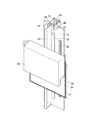
図1は、本発明に係る画像読取装置1の実施の一形態を示したもので、この画像読取装置1の正面側上部には、画像が記録された記録媒体としての輝尽性蛍光体シート14を収納したカセッテ2を挿入する挿入口3が設けられており、この挿入口3の下端部には、カセッテ2を画像読取装置1の内部へ送り込む送込ローラ4が設けられている。
FIG. 1 shows an embodiment of an image reading apparatus 1 according to the present invention, and a photostimulable phosphor sheet as a recording medium on which an image is recorded is provided on the upper part on the front side of the image reading apparatus 1. An
画像読取装置1の正面側上部であって挿入口3の後方には、読取り処理がなされたカセッテ2を取り出す取出口5が設けられており、この取出口5の下端部には、カセッテ2を画像読取装置1の外部に送り出す送出ローラ6が設けられている。
At the upper part on the front side of the image reading apparatus 1 and behind the
画像読取装置1の正面側下部には、カセッテ2を所定位置に搬送するカセッテ搬送装置7が、下端を支軸として図示しない駆動機構により回動可能に設けられており、挿入口3に対応する位置a、取出口5に対応する位置b、カセッテ2が略垂直となる位置cの各位置において停止可能とされている。
A cassette conveying device 7 that conveys the
カセッテ搬送装置7は、上面及び背面が開放された箱状のカセッテ支持部8を有しており、カセッテ支持部8の内部には、カセッテ2の下端部を支持して昇降可能な昇降台9が設けられている。
The cassette transport device 7 has a box-shaped cassette support portion 8 whose upper surface and back surface are open, and an
また、カセッテ支持部8の内部には、カセッテ2を、輝尽性蛍光体シート14を背面から保持するバック板10と輝尽性蛍光体シート14の表面を覆うフロント板11とに分離可能とするロック解除機構(図示しない)が設けられている。ロック解除機構としては、例えば、特開2002−278000号公報に開示されているロック解除機構を用いることができる。
Further, inside the cassette support portion 8, the
画像読取装置1の背面側には、基台12から鉛直方向に延在する板状の支持部材13が設けられており、この支持部材13には、輝尽性蛍光体シート14を保持してリニアモータにより鉛直方向に移動可能な移動体15と、移動体15と釣り合う釣合錘16とが、連結部材17を介して相対的に昇降可能に支持されている。この支持部材13の正面略中央には、鉛直方向に移動体15をガイドするガイド部としての第1ガイドレール18が設けられており、背面には、鉛直方向に釣合錘16をガイドする第2ガイドレール19が設けられている。
A plate-
移動体15は、図1から図3に示すように、輝尽性蛍光体シート14を支持したカセッテ2のバック板10を保持する板状の保持部20を有している。この保持部20の表面には、ラバーマグネットが設けられているとともに、カセッテ2のバック板10は、合成樹脂により形成された本体に強磁性体シートを貼着して構成されており、これにより、バック板10が保持部20に磁力で接着し、保持されるようになっている。
As shown in FIGS. 1 to 3, the moving
保持部20の裏面には、取付部材21が設けられており、この取付部材21の保持部取付け面と対向する面には、第1ガイドレール18に案内される断面コ字形状の第1被ガイド部材22が、取付部材21と一体的に設けられている。
A mounting
取付部材21の一側方には、リニアモータを構成するマグネット部23が、支持部材13と一体形成された支持片24に支持され鉛直方向に延在して設けられている。マグネット部23は、断面円形状の永久磁石のN極同士あるいはS極同士を複数連結してシャフト状に形成されている。
On one side of the
一方、取付部材21の側部には、リニアモータを構成する可動コイル25が設けられている。この可動コイル25は、円筒状に形成されたコイルを有しており、このコイルは箱状のカバー部材により覆われている。そして、リニアモータは、可動コイル25の中心をマグネット部23が貫通するように構成されている。
On the other hand, a
支持部材13の正面であって第1ガイドレール18をはさんでマグネット部23と反対側には、移動体15の位置や移動速度を検知するためのエンコーダを構成するリニアスケール26が、鉛直方向に延在して設けられている。また、保持部20のリニアスケール26と対向する位置には、エンコーダを構成しリニアスケール26を読み取るセンサ部27が設けられている。
On the front side of the
釣合錘16は、第2ガイドレール19に案内される断面コ字形状の第2被ガイド部材37を有している。
The
支持部材13の上方の正面側には、第1プーリ28が設けられているとともに、背面側には、第2プーリ29及び第3プーリ30が上下にわたって設けられている。これらプーリ28,29,30には、ベルト状の連結部材17が渡されており、この連結部材17の正面側端部には移動体15が締結され、背面側端部には釣合錘16が締結されている。連結部材17としてスチールワイヤーを用いることもできる。
A
なお、移動体15は、マグネット部23に対して移動可能な部材をさし、本実施形態においては、可動コイル25、保持部20、取付部材21及び第1被ガイド部材22により構成される。
The moving
また、第1プーリ28の軸部には、第1プーリ28の回転動作を停止させるトルクリミッタ、ワンウェイクラッチ、電磁ブレーキ等のブレーキ機構31が設けられている。
Further, a
移動体15の可動範囲の上部であって移動体15と対向する位置には、保持部20に保持された輝尽性蛍光体シート14に蓄積、記録された放射線エネルギーを読み取る読取部32が設けられている。
A
読取部32は、レーザ光L1を移動体15の移動方向と直交する方向に走査させながら輝尽性蛍光体シート14に対して照射するレーザ光照射装置33と、レーザ光照射装置33により輝尽性蛍光体シート14にレーザ光L1が照射されることで励起された輝尽発光光L2を導く導光板34と、導光板34により導かれた輝尽発光光L2を集光する集光管35と、集光管35により集光された輝尽発光光L2を電気信号に変換する光電変換器38とを有している。
The
読取部32の下方には、読取部32により放射線エネルギーの読取処理がなされた後、輝尽性蛍光体シート14に残留する放射線エネルギーを放出させるために輝尽性蛍光体シート14に対して消去光を照射する消去装置36が設けられている。
Below the
次に、本実施形態の作用について説明する。 Next, the operation of this embodiment will be described.
画像の読取処理を行う際には、カセッテ搬送装置7を挿入口3に対応する位置aに待機させ、この状態で、挿入口3より放射線画像が記録された輝尽性蛍光体シート14が収納されたカセッテ2を挿入すると、送込ローラ4によりカセッテ2がカセッテ搬送装置7に対して送り込まれる。すると、昇降台9がカセッテ2の下端部を支持した状態で下降し、カセッテ2がカセッテ搬送装置7内に収容され、ロック解除機構が作動することにより、カセッテ2がフロント板11と輝尽性蛍光体シート14を保持したバック板10とに分離可能な状態となる。
When performing the image reading process, the cassette carrying device 7 is put on standby at a position a corresponding to the
その後、カセッテ搬送装置7をカセッテ2が略垂直となる位置cまで移動させる。このとき、移動体15を可動範囲の最下端に位置させておくことにより、保持部20とカセッテ2のバック板10とが対向した状態となり、磁力により輝尽性蛍光体シート14を支持したバック板10が保持部20に吸着され、フロント板11と分離して輝尽性蛍光体シート14の表面が露出した状態で保持部20に保持される。なお、カセッテ搬送装置7は、フロント板11を保持させた状態で、取出口5に対応する位置bに退避させておくとよい。
Thereafter, the cassette carrying device 7 is moved to a position c where the
その後、リニアモータを駆動させて、移動体15を第1ガイドレール18に沿って上昇させる。これにより、輝尽性蛍光体シート14が読取部32に対向する位置まで搬送され、レーザ光照射装置33によりレーザ光L1が走査されて、これにより励起された輝尽発光光L2が、導光板34により導かれて集光管35に集光され、光電変換器38により電気信号に変換される。
Thereafter, the linear motor is driven to raise the moving
ここで、マグネット部23がシャフト状に形成されていることから、可動コイル25は、円筒状に形成されたコイルを箱状のカバー部材により覆った形状とされており、保持部20に固定される上で剛性の高い形状になっている。したがって、可動コイルを必要以上に大きくすることなく、リニアモータの搬送速度に対して移動体15に遅れを生じさせることを防止でき、振動を発生させることなく輝尽性蛍光体シート14が滑らかに搬送される。また、移動体15の上昇に伴ってプーリ28,29,30が回転して釣合錘16が第2ガイドレール19に沿って自重落下するため、リニアモータによる推力を低減させることができ、よりマグネット部及び可動コイルを小型化することが可能となる。
Here, since the
輝尽性蛍光体シート14の下端部まで読取部32による読取処理が完了すると、リニアモータを停止させる。このとき、ブレーキ機構31により第1プーリ28の回転が停止され、移動体15が安定した状態で停止する。
When the reading process by the
その後、再びリニアモータを駆動させて、移動体15を第1ガイドレール18に沿って下降させると同時に、消去装置36により輝尽性蛍光体シート14に対して消去光を照射させ、これにより、輝尽性蛍光体シート14に残存する放射線画像を消去させる。
Thereafter, the linear motor is driven again, and the moving
その後、移動体15が可動範囲の最下端まで下降して停止すると、カセッテ搬送装置7をカセッテ2が略垂直となる位置cに回動させる。これにより、バック板10とフロント板11とが合体した状態でロックが施される。
Then, when the moving
そして、図示しない駆動機構によりカセッテ搬送装置7を取出口5に対応する位置bに回動させながら、カセッテ2を保持部20から引き離し、昇降台9を上昇させるとともに、送出ローラ6を作動させることにより、カセッテ2が取出口5より取り出される。
And while rotating the cassette conveying apparatus 7 to the position b corresponding to the
以上より、本実施形態によれば、可動コイル25が保持部20に固定される上で剛性の得やすい形状となり、可動コイル25を必要以上に大きくすることなく、リニアモータの搬送速度に対して移動体15に遅れが生じることが防止され、振動を発生させることなく、記録媒体又は記録部が滑らかに搬送されるため、小型で低コストな装置構成により、高精細な画像を得ることができる。
As described above, according to the present embodiment, the shape is easy to obtain rigidity when the
また、円筒状に形成された可動コイル25をシャフト状のマグネット部23が貫くようになっているため、磁束の利用効率が良く、大きい推力を得たい場合にも、マグネット部23の大きさを必要以上に大きくせずにすむことからも、装置の小型化及び低コスト化を図ることができる。
In addition, since the shaft-shaped
さらに、移動体15をリニアモータにより上昇させる際に、釣合錘16が自重落下することから、リニアモータによる推力を低減させることができるため、マグネット部23及び可動コイル25を小型化することができ、ひいては装置の小型化及び低コスト化を図ることができる。
Furthermore, when the moving
次に、本発明の第2実施形態を、図4を参照して説明する。 Next, a second embodiment of the present invention will be described with reference to FIG.
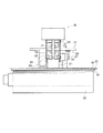
図4は、本発明に係る画像形成装置40の実施の一形態を示したもので、この画像形成装置40の内部には、複数の記録媒体41を積層して収容する収容トレイ42が設けられており、この収容トレイ42の一端部上側には、画像を記録しようとする記録媒体41を一枚ずつ収容トレイ42から取り出す取出し装置43が設けられている。
FIG. 4 shows an embodiment of the
なお、記録媒体41としては、色材層を有する第1シートとベース層を有する第2シートとから形成され、レーザ光を照射することにより色材層とベース層との間で材料のアブレーションを発生させ、色材層を第2シートに転写することにより画像を形成可能な記録媒体41が適用される。
The
この収容トレイ42下側方には、記録媒体41を支持する円筒状の支持ドラム44が回転自在に配設されており、この支持ドラム44は、ドラム駆動機構によって回転駆動されるようになっている。また、支持ドラム44の周面には、記録媒体41の前端部を全幅にわたって把持するグリッパ45a及び記録媒体41の後端部を全幅にわたって把持するグリッパ45bが、支持ドラム44の軸方向に延在して設けられている。
A
支持ドラム44の側方には、支持ドラム44に摺接して従動回転する従動ローラ46が、支持ドラム44に対して接離可能に設けられている。
On the side of the
画像形成装置40の上部には、画像が記録された記録媒体41を排出する排出トレイ47が設けられている。
A
画像形成装置40の内部には、収容トレイ42から供給された記録媒体41を、支持ドラム44の周面上部へ搬送し、記録媒体41が支持ドラム44の周面に沿って搬送された後に、支持ドラム44の周面上部から排出トレイ47へ排出させる搬送経路が設けられている。この搬送経路の所定位置には、搬送方向に記録媒体41を搬送するための複数対の搬送ローラ48が設けられている。
Inside the
支持ドラム44の周面側方には、支持ドラム44に支持された記録媒体41に対してレーザ光を照射する記録部としてのレーザ光照射装置49が設けられており、レーザ光照射装置49の下部には、レーザ光照射装置49を保持してリニアモータにより記録媒体41の搬送方向と直交する方向に往復移動可能な移動体50が設けられている。
A laser
移動体50の下方には、記録媒体41の搬送方向と直交する方向に延在する板状の支持部材51が設けられており、この支持部材51の上面略中央には、記録媒体41の幅方向に移動体50をガイドするガイド部としてのガイドレール52が設けられている。
A plate-
移動体50は、レーザ光照射装置49を保持する板状の保持部53を有している。この保持部53の裏面には、取付部材54が設けられており、この取付部材54の保持部取付け面と対向する面には、ガイドレール52に案内される断面コ字形状の被ガイド部材55が、取付部材54と一体的に設けられている。
The moving
取付部材54の一側方には、リニアモータを構成するマグネット部56が、支持部材51と一体形成された支持片57に支持され記録媒体41の搬送方向と直交する方向に延在して設けられている。マグネット部56は、断面円形状の永久磁石のN極同士あるいはS極同士を複数連結してシャフト状に形成されている。
On one side of the mounting
一方、取付部材54の側部には、リニアモータを構成する可動コイル58が設けられている。可動コイル58は、円筒状に形成されたコイルを有しており、このコイルは箱状のカバー部材により覆われている。そして、リニアモータは、可動コイル58の中心をマグネット部56が貫通するように構成されている。
On the other hand, a
支持部材51の上面であってガイドレール52をはさんでマグネット部56とは反対側には、移動体50の位置や移動速度を検知するためのエンコーダを構成するリニアスケール59が、記録媒体41の幅方向に延在して設けられている。また、保持部53のリニアスケール59と対向する位置には、エンコーダを構成しリニアスケール59を読み取るセンサ部60が設けられている。
On the upper surface of the
支持ドラム44より搬送経路下流側には、レーザ光照射装置49により露光された記録媒体41の第1シートと第2シートとを剥離する剥離装置61が設けられており、排出トレイ47の下方には、剥離装置61により第2シートと剥離された第1シートを巻き取って回収する回収ロール62が設けられている。また、剥離装置61より搬送経路下流側には、画像が形成された第2シートを排出トレイ47に排出させる排出ローラ63が設けられている。
A peeling
次に、本実施形態の作用について説明する。 Next, the operation of this embodiment will be described.
画像形成装置40に画像情報が送られると、取出し装置43が作動して、収容トレイ42に収容された最上位の記録媒体41を取出し、搬送ローラ48が回転動作して、この取出された記録媒体41を搬送させる。
When the image information is sent to the
記録媒体41が支持ドラム44の上部周面近傍まで到達したら、ドラム駆動機構により支持ドラム44が、記録媒体41の前端部をグリッパ45aに把持した状態で、図4において時計方向に回転動作する。支持ドラム44の回転に伴ってグリッパ45aが従動ローラ46の位置を通過すると、従動ローラ46が支持ドラム44に対して当接して、記録媒体41を支持ドラム44の周面に保持させる。そして、支持ドラム44の回転に伴ってグリッパ45bが、記録媒体41の後端部位置まで移動して、記録媒体41の後端部を把持すると、従動ローラ46が支持ドラム44から離間する。
When the
その後、支持ドラム44が図4において時計方向と反対方向に回転動作し、支持ドラム44の回転に伴って記録媒体41がレーザ光照射装置49の位置まで送られると、レーザ光照射装置49により画像情報に基づいて、記録媒体41に対してレーザ光が照射される。このとき、レーザ光照射装置49は、移動体50がリニアモータの駆動により記録媒体41の搬送方向と直交する方向に往復移動するのに伴って、記録媒体41に対してレーザ光を走査させる。
Thereafter, the
ここで、マグネット部56がシャフト状に形成されていることから、可動コイル58は、円筒状に形成されたコイルを箱状のカバー部材により覆った形状とされており、保持部53に固定される上で剛性の高い形状になっている。したがって、可動コイル58を必要以上に大きくすることなく、リニアモータの搬送速度に対して移動体50に遅れを生じさせることを防止でき、振動を発生させることなくレーザ光照射装置49が滑らかに走査される。
Here, since the
レーザ光照射装置49によるレーザ光の照射が完了すると、記録媒体41を搬送ローラ48により搬送経路に沿って搬送させる。
When the laser light irradiation by the laser
記録媒体41は、剥離装置61の位置まで搬送されると、剥離装置61により第1シートと第2シートとに剥離される。そして、第1シートは回収ロール62に回収され、第2シートは、搬送ローラ48及び排出ローラ63により、排出トレイ47に排出される。
When the
以上より、本実施形態によれば、可動コイル58が保持部53に固定される上で剛性の得やすい形状となり、可動コイル58を必要以上に大きくすることなく、リニアモータの搬送速度に対して移動体50に遅れが生じることが防止され、振動が発生することなく、レーザ光照射装置49が滑らかに搬送されるため、小型で低コストな装置構成により、高精細な画像を得ることができる。
As described above, according to the present embodiment, the
また、円筒状に形成された可動コイル58をシャフト状のマグネット部56が貫くようになっているため、磁束の利用効率が良く、大きい推力を得たい場合にも、マグネット部56の大きさを必要以上に大きくせずにすむことからも、装置の小型化及び低コスト化を図ることができる。
In addition, since the shaft-shaped
1 画像読取装置
2 カセッテ
14 輝尽性蛍光体シート(記録媒体)
15 移動体
16 釣合錘
17 連結部材
18 第1ガイドレール(ガイド部)
19 第2ガイドレール
20 保持部
23 マグネット部
25 可動コイル
31 ブレーキ機構
32 読取部
40 画像形成装置
41 記録媒体
44 支持ドラム
49 レーザ光照射装置(記録部)
50 移動体
52 ガイドレール(ガイド部)
53 保持部
56 マグネット部
58 可動コイル
DESCRIPTION OF SYMBOLS 1
15
19
50 Moving
53
Claims (12)
Priority Applications (3)
| Application Number | Priority Date | Filing Date | Title |
|---|---|---|---|
| JP2003301077A JP2005073023A (en) | 2003-08-26 | 2003-08-26 | Image reading apparatus and image forming apparatus |
| US10/921,238 US20050046908A1 (en) | 2003-08-26 | 2004-08-18 | Moving device, image reading device and image forming apparatus |
| EP04019704A EP1511162A1 (en) | 2003-08-26 | 2004-08-19 | Moving device, image reading device and image forming apparatus |
Applications Claiming Priority (1)
| Application Number | Priority Date | Filing Date | Title |
|---|---|---|---|
| JP2003301077A JP2005073023A (en) | 2003-08-26 | 2003-08-26 | Image reading apparatus and image forming apparatus |
Publications (2)
| Publication Number | Publication Date |
|---|---|
| JP2005073023A true JP2005073023A (en) | 2005-03-17 |
| JP2005073023A5 JP2005073023A5 (en) | 2006-10-05 |
Family
ID=34405805
Family Applications (1)
| Application Number | Title | Priority Date | Filing Date |
|---|---|---|---|
| JP2003301077A Pending JP2005073023A (en) | 2003-08-26 | 2003-08-26 | Image reading apparatus and image forming apparatus |
Country Status (1)
| Country | Link |
|---|---|
| JP (1) | JP2005073023A (en) |
-
2003
- 2003-08-26 JP JP2003301077A patent/JP2005073023A/en active Pending
Similar Documents
| Publication | Publication Date | Title |
|---|---|---|
| JP3971993B2 (en) | Sheet body conveying apparatus and radiation image reading apparatus | |
| US7274033B2 (en) | Reading method for radiation image information and radiation image reading apparatus | |
| JP2005073023A (en) | Image reading apparatus and image forming apparatus | |
| JP2005070533A (en) | Moving device, image reader, and image forming device | |
| JP4241663B2 (en) | Image reading device | |
| US20090078893A1 (en) | Image reading apparatus | |
| JP2007020083A (en) | Image reader, image forming device and conveyance control method | |
| JP2006141141A (en) | Transport device, image scanner, and image forming apparatus | |
| JPWO2006043425A1 (en) | Image reading device | |
| JP4342994B2 (en) | Radiation image recording / reading apparatus and radiation image recording cassette | |
| JP2007017870A (en) | Image reader and image forming apparatus | |
| JP2006136051A (en) | Linear motor | |
| JP2008122487A (en) | Image reading apparatus | |
| JP2005073019A (en) | Image reading apparatus and image forming apparatus | |
| JP2006137547A (en) | Conveyance device, image reading device, and image forming device | |
| JP2003270746A (en) | Radiograph reader and radiograph read system | |
| JP2005073042A (en) | Image reader and image recorder | |
| JP2005070525A (en) | Image scanner and image recorder | |
| US20050046908A1 (en) | Moving device, image reading device and image forming apparatus | |
| JP2003344964A (en) | Radiation image reader | |
| JP2007017869A (en) | Image scanner and image forming apparatus | |
| JP2004264711A (en) | Image scanner | |
| JP4574359B2 (en) | Radiation image acquisition method | |
| JP2003270745A (en) | Radiograph reader | |
| JPS6367859A (en) | Control method for sheet body conveying mechanism |
Legal Events
| Date | Code | Title | Description |
|---|---|---|---|
| A521 | Written amendment |
Free format text: JAPANESE INTERMEDIATE CODE: A523 Effective date: 20060822 |
|
| A621 | Written request for application examination |
Free format text: JAPANESE INTERMEDIATE CODE: A621 Effective date: 20060822 |
|
| A977 | Report on retrieval |
Free format text: JAPANESE INTERMEDIATE CODE: A971007 Effective date: 20080902 |
|
| A131 | Notification of reasons for refusal |
Free format text: JAPANESE INTERMEDIATE CODE: A131 Effective date: 20080909 |
|
| A02 | Decision of refusal |
Free format text: JAPANESE INTERMEDIATE CODE: A02 Effective date: 20090120 |