JP4236609B2 - Mounting structure of rotary joint on turning work machine - Google Patents

Mounting structure of rotary joint on turning work machine Download PDF

Info

Publication number
JP4236609B2
JP4236609B2 JP2004136553A JP2004136553A JP4236609B2 JP 4236609 B2 JP4236609 B2 JP 4236609B2 JP 2004136553 A JP2004136553 A JP 2004136553A JP 2004136553 A JP2004136553 A JP 2004136553A JP 4236609 B2 JP4236609 B2 JP 4236609B2
Authority
JP
Japan
Prior art keywords
rotary joint
frame
plate
traveling
swivel
Prior art date
Legal status (The legal status is an assumption and is not a legal conclusion. Google has not performed a legal analysis and makes no representation as to the accuracy of the status listed.)
Expired - Lifetime
Application number
JP2004136553A
Other languages
Japanese (ja)
Other versions
JP2005315027A (en
JP2005315027A5 (en
Inventor
謙三 古賀
静夫 下家
好洋 加藤
孝則 松本
Current Assignee (The listed assignees may be inaccurate. Google has not performed a legal analysis and makes no representation or warranty as to the accuracy of the list.)
Kubota Corp
Original Assignee
Kubota Corp
Priority date (The priority date is an assumption and is not a legal conclusion. Google has not performed a legal analysis and makes no representation as to the accuracy of the date listed.)
Filing date
Publication date
Application filed by Kubota Corp filed Critical Kubota Corp
Priority to JP2004136553A priority Critical patent/JP4236609B2/en
Publication of JP2005315027A publication Critical patent/JP2005315027A/en
Publication of JP2005315027A5 publication Critical patent/JP2005315027A5/ja
Application granted granted Critical
Publication of JP4236609B2 publication Critical patent/JP4236609B2/en
Anticipated expiration legal-status Critical
Expired - Lifetime legal-status Critical Current

Links

Images

Landscapes

  • Component Parts Of Construction Machinery (AREA)

Description

本発明は、バックホー等の旋回作業機におけるロータリジョイントの取付構造に関するものである。   The present invention relates to a rotary joint mounting structure in a turning work machine such as a backhoe.

バックホー等の旋回作業機には、掘削装置を備えた旋回体を、走行装置上に上下方向の旋回軸心回りに回動自在に備え、走行装置の走行フレームの旋回軸心上に、ロータリジョイントが取り付けられるものがあり、この種の従来の旋回作業機のロータリジョイントの取付構造は、走行装置の走行フレームの底板に、直接又は取付ブラケット等を介して、ロータリジョイントを載置して、ロータリージョイントの底面を走行フレームの底板に又は取付ブラケット等を介してボルト等の固定具で固定していた(例えば特許文献1、特許文献2)。
特開2001−271380号公報 特開平11−93209号公報
A swivel working machine such as a backhoe is provided with a swivel body equipped with an excavator so as to be rotatable about a swivel axis in the vertical direction on the travel device, and on a swivel axis of a travel frame of the travel device, a rotary joint The rotary joint mounting structure of this type of conventional swivel work machine has a rotary joint mounted directly on the bottom plate of the traveling frame of the traveling device or via a mounting bracket. The bottom surface of the joint is fixed to the bottom plate of the traveling frame or a fixing tool such as a bolt via a mounting bracket (for example, Patent Document 1 and Patent Document 2).
JP 2001-271380 A JP-A-11-93209

従って、従来の場合、ロータリジョイントに回動トルクがかかると、底面側を支点にロータリジョイントを大きく揺動させるように作用し、このため走行フレームの底板のロータリジョイント取付部分や取付ブラケット等に大きな強度を持たせる必要があった。
また、ボルト等の固定具が緩むと、ロータリジョイントが底面側を支点に大きく揺動して、ロータリジョイントに連結した油圧ホースを破損したりするおそれが大であった。
そこで、本発明は、上記問題点に鑑み、ロータリジョイント取付部分の強度が小さくて済み、しかもボルト等の固定具が緩んでも、ロータリジョイントが回動トルクによって大きく揺動しないようにしたものである。
Therefore, in the conventional case, when a rotational torque is applied to the rotary joint, the rotary joint acts so as to largely swing around the bottom surface side. Therefore, the rotary joint mounting portion on the bottom plate of the traveling frame, the mounting bracket, etc. It was necessary to have strength.
In addition, when a fixing tool such as a bolt is loosened, there is a high possibility that the rotary joint swings with the bottom surface side as a fulcrum and the hydraulic hose connected to the rotary joint is damaged.
Therefore, in view of the above-described problems, the present invention is such that the strength of the rotary joint mounting portion is small, and the rotary joint does not swing greatly due to the rotational torque even if the fixture such as a bolt is loosened. .

この技術的課題を解決するための本発明の技術的手段は、作業装置を備えた旋回体を、走行装置上に上下方向の旋回軸心回りに回動自在に備え、走行装置の走行フレームの旋回軸心X上に、ロータリジョイントが取り付けられた旋回作業機におけるロータリジョイントの取付構造において、
走行フレームの底板に支持ステーが上方突設され、ロータリジョイントの上下方向中央部が、前記支持ステーを介して走行フレームの底板に取り付けられ
前記支持ステーはロータリジョイントに対して一対設けられ、各支持ステーへのロータリジョイントの取付部は、互いに上下にずらされている点にある。
The technical means of the present invention for solving this technical problem is provided with a revolving body provided with a working device, which is rotatable on a traveling device around a vertical pivot axis, and is provided on a traveling frame of the traveling device. In the rotary joint mounting structure in the swing work machine in which the rotary joint is mounted on the swing axis X,
A support stay projects upward from the bottom plate of the traveling frame, and the vertical center of the rotary joint is attached to the bottom plate of the traveling frame via the support stay ,
A pair of the support stays are provided with respect to the rotary joints, and the attachment portions of the rotary joints to the respective support stays are shifted vertically .

また、本発明の他の技術的手段は、前記支持ステーは、ロータリジョイントの前後に一対設けられている点にある。
また、本発明の他の技術的手段は、前記ロータリジョイントに、側面視L字状の取付部材が設けられ、このL字状の取付部材の一片が、ロータリジョイント側に固定され、取付部材の他片が、前記支持ステーのロータリジョイント取付部に、載置して固定されている点にある。
Another technical means of the present invention, the supporting stay is that are a pair provided et the front and rear of the rotary joint.
According to another technical means of the present invention, the rotary joint is provided with an L-shaped attachment member in a side view, and one piece of the L-shaped attachment member is fixed to the rotary joint side. The other piece is that it is placed and fixed on the rotary joint mounting portion of the support stay.

本発明によれば、ロータリジョイント取付部分の強度が小さくて済み、しかもボルト等の固定具が緩んでも、ロータリジョイントが回動トルクによって大きく揺動しないようになる。   According to the present invention, the strength of the rotary joint mounting portion can be small, and even if a fixture such as a bolt is loosened, the rotary joint does not swing greatly due to the rotational torque.

以下、本発明の実施の形態を図面を参照して説明する。
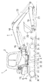
図1において、1は旋回作業機として例示するバックホーであり、該バックホー1は上部の旋回体2(機体)と、下部の走行装置3とから主構成されている。
なお、バックホー1の走行方向(図1の左右方向)を前後方向といい、この前後方向に直交する横方向(図1の紙面貫通方向)を左右方向という。
旋回体2は、走行装置3上に上下方向の旋回軸心X回りに旋回自在に支持された旋回台6と、旋回台6の前部に設けられた作業装置(掘削装置)7と、旋回台6に設けられた運転席と、エンジン、燃料タンク、油圧ポンプ、作動油タンク,コントロールバルブ、ラジエータ、オイルクーラ、リザーブタンク、バッテリー等の旋回台6に搭載された各種機器等とを備えて構成されている。
Hereinafter, embodiments of the present invention will be described with reference to the drawings.
In FIG. 1, reference numeral 1 denotes a backhoe exemplified as a turning work machine, and the backhoe 1 mainly includes an upper turning body 2 (airframe) and a lower traveling device 3.
Note that the traveling direction of the backhoe 1 (the left-right direction in FIG. 1) is referred to as the front-rear direction, and the lateral direction orthogonal to the front-rear direction (the paper penetration direction in FIG.
The swivel body 2 includes a swivel base 6 that is supported on the travel device 3 so as to be pivotable around a swivel axis X in the vertical direction, a work device (excavation device) 7 provided at the front of the swivel base 6, A driver's seat provided on the base 6 and various devices mounted on the swivel base 6 such as an engine, a fuel tank, a hydraulic pump, a hydraulic oil tank, a control valve, a radiator, an oil cooler, a reserve tank, and a battery. It is configured.

旋回台6は、走行装置3上に旋回ベアリング11を介して旋回軸心X廻りに旋回自在に支持された旋回基板12を備えると共にこの旋回基板12上に補強部材や、各種機器等を取付固定するための取付部材等を固定してなる旋回フレームと、この旋回フレームの後部に取付固定されていて旋回台6前部の作業装置7等に対する重量バランスを図ると共に旋回台6の後部を構成するカウンタウエイト13とから主構成されている。
旋回基板12の前部には、旋回台6から前方突出状した支持ブラケット16が設けられ、この支持ブラケット16に、揺動ブラケット17が上下軸廻りに左右揺動自在に支持されている。
The swivel base 6 includes a swivel board 12 that is supported on the travel device 3 via a swivel bearing 11 so as to be pivotable about a swivel axis X, and a reinforcing member, various devices, and the like are mounted and fixed on the swivel board 12. And a rear part of the swivel base 6, and a rear part of the swivel base 6, and a rear part of the swivel base 6. Mainly composed of a counterweight 13.
A support bracket 16 projecting forward from the swivel base 6 is provided at the front portion of the swivel board 12, and a swing bracket 17 is supported on the support bracket 16 so as to be swingable left and right around the vertical axis.

揺動ブラケット17に横軸廻りに揺動自在に支持されたブーム18と、このブーム18の先端側に横軸廻りに揺動自在に支持されたアーム19と、このアーム19の先端側にスクイ・ダンプ動作可能に取り付けられたバケット20とから前記作業装置7が主構成されており、これらブーム18、アーム19、バケット20は、それぞれ油圧シリンダからなるブームシリンダ21、アームシリンダ22、バケットシリンダ23によって作動可能とされている。
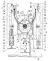
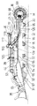
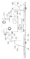
図2〜図7において、走行装置3は、走行フレーム27を備え、走行フレーム27の左右両側に、後部に配置された駆動輪30、前部に配置されたアイドラ31(遊転輪)、これら駆動輪30とアイドラ31との間に配置された複数個の転輪32及びキャリアローラ33を回転自在に支持すると共に、これら駆動輪30、アイドラ31、キャリアローラ33及び転輪32にゴム製又は鉄製の無端ベルト状のクローラベルト34を巻き掛け、駆動輪30を油圧モータM等で駆動してクローラベルト34を循環回走させるように構成した左右一対のクローラ走行体36が設けられている。走行装置3の前部にはドーザ35が備えられている。
A boom 18 supported by the swing bracket 17 so as to be swingable about the horizontal axis, an arm 19 supported so as to be swingable about the horizontal axis on the tip side of the boom 18, and a squeeze on the tip side of the arm 19. The working device 7 is mainly composed of a bucket 20 attached so as to be capable of dumping. The boom 18, the arm 19, and the bucket 20 are a boom cylinder 21, an arm cylinder 22, and a bucket cylinder 23, each of which is a hydraulic cylinder. It can be operated by.
2 to 7, the traveling device 3 includes a traveling frame 27, on both the left and right sides of the traveling frame 27, drive wheels 30 disposed at the rear, idlers 31 (idling wheels) disposed at the front, these A plurality of rollers 32 and a carrier roller 33 disposed between the driving wheel 30 and the idler 31 are rotatably supported, and the driving wheel 30, the idler 31, the carrier roller 33, and the rollers 32 are made of rubber or A pair of left and right crawler traveling bodies 36 configured to wrap around an iron endless belt-like crawler belt 34 and drive the driving wheel 30 with a hydraulic motor M or the like to circulate and rotate the crawler belt 34 are provided. A dozer 35 is provided at the front of the traveling device 3.

前記走行フレーム27は、図2〜図5に示すように、大別して、センタフレーム37と、このセンタフレーム37の左右両側に配置されたサイドフレーム38とを備えて構成されている。
センタフレーム37は、上板39と、底板40とを有し、これら上板39と底板40との対向内面間に立設されていて、その上下端縁が上板39及び底板40に固着された左右の側縦壁42と、後縦壁43と、前縦壁44とを有する。これら上板39、底板40、縦壁42,43,44は鉄板又は鋼板等で形成されている。すなわち、センタフレーム37の主要部は、上板39と底板40とを縦壁42,43,44によって連結した立体構造物を構成している。
As shown in FIGS. 2 to 5, the traveling frame 27 is roughly configured to include a center frame 37 and side frames 38 disposed on the left and right sides of the center frame 37.
The center frame 37 has an upper plate 39 and a bottom plate 40, and is erected between opposed inner surfaces of the upper plate 39 and the bottom plate 40, and upper and lower edges thereof are fixed to the upper plate 39 and the bottom plate 40. The left and right side vertical walls 42, the rear vertical wall 43, and the front vertical wall 44 are provided. The upper plate 39, the bottom plate 40, and the vertical walls 42, 43, and 44 are formed of an iron plate or a steel plate. That is, the main part of the center frame 37 constitutes a three-dimensional structure in which the upper plate 39 and the bottom plate 40 are connected by the vertical walls 42, 43, 44.

センタフレーム37は、その主要部の中央部が平面視略矩形状に形成されていて、その上面に旋回ベアリング11を介して旋回体3を回転自在に支持するとともに、その前部にドーザ35を支持している。
具体的には、センタフレーム37の中央部における上板39には、上下方向に貫通する円形の開口46が形成されるとともに、この開口46の周りに、旋回ベアリング11を取り付けるためのボルト孔が多数形成され、この部分が旋回ベアリング11の受け部Aを構成している。
The center portion of the center frame 37 is formed in a substantially rectangular shape in plan view. The center frame 37 rotatably supports the swivel body 3 via the swivel bearing 11 on the upper surface thereof, and a dozer 35 on the front portion thereof. I support it.
Specifically, a circular opening 46 penetrating in the vertical direction is formed in the upper plate 39 in the center portion of the center frame 37, and a bolt hole for attaching the swivel bearing 11 is formed around the opening 46. A large number are formed, and this portion constitutes the receiving portion A of the slewing bearing 11.

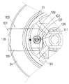
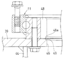
図10及び図11に示すように、センタフレーム37の上板39における開口46の内周面が、旋回ベアリング11のインナーギヤ48の歯底縁48a近傍に形成され、開口46の内周面が、旋回ベアリング11のインナーギヤ48の歯底縁48aよりも径方向外方に配置されると共に、開口46の内周面の上端側に、インナーギヤ48の歯底縁48a直下から開口46の内方に向けて下降傾斜した土だまり防止面49が形成されている。従って、旋回ベアリング11のインナーギヤ48側から落下した土は、上板39の開口46縁部上に落ちることなく、土だまり防止面49を滑り落ちて、開口46から落下するため、土が上板39の開口46縁部上に貯まることがなくなる。   As shown in FIGS. 10 and 11, the inner peripheral surface of the opening 46 in the upper plate 39 of the center frame 37 is formed in the vicinity of the tooth bottom edge 48 a of the inner gear 48 of the slewing bearing 11, and the inner peripheral surface of the opening 46 is The slewing bearing 11 is disposed radially outward from the tooth bottom edge 48a of the inner gear 48, and is located on the upper end side of the inner peripheral surface of the opening 46 from directly below the tooth bottom edge 48a of the inner gear 48. An accumulation prevention surface 49 inclined downward is formed. Accordingly, the soil that has fallen from the inner gear 48 side of the slewing bearing 11 does not fall on the edge of the opening 46 of the upper plate 39, slides down the accumulation prevention surface 49 and falls from the opening 46, so It will not accumulate on the edge of the opening 46 of the plate 39.

また、センタフレーム37の中央部の前部には、左右方向中央部に支持ブラケット53が左右一対設けられていると共に、この支持ブラケット53の左右両側にも支持ブラケット54が左右一対ずつ設けられている。
中央部の支持ブラケット54には、ドーザ35を昇降するドーザシリンダ55の後端側が左右方向の軸心廻りに回動自在に枢支されており、左右の支持ブラケット54には、ドーザ35の揺動フレームを構成する左右の支持アーム57の後端側が左右方向の軸心廻りに回動自在に枢支されている。
In addition, a pair of left and right support brackets 53 are provided at the front of the center portion of the center frame 37 at the center in the left-right direction, and a pair of left and right support brackets 54 are provided on both left and right sides of the support bracket 53. Yes.
The rear end side of the dozer cylinder 55 that moves up and down the dozer 35 is pivotally supported by the support bracket 54 at the center so as to be rotatable about the left and right axis. The left and right support brackets 54 swing the dozer 35. The rear end sides of the left and right support arms 57 that constitute the moving frame are pivotally supported so as to be rotatable around a horizontal axis.

前記センタフレーム37の左右両側部には、中央部から左右方向外方へ突出して左右サイドフレーム38に連結される左右の脚部C1を有している。
なお、前記底板40は、センタフレーム37の中央部から脚部C1に亘って1枚の板材で形成されていて、該底板40の左右両側部分で脚部C1の下面を構成しており、これに対して、上板39は、旋回ベアリング受け部Aが形成される中央部分39Aと、脚部C1の上面を構成する板材からなる上部壁39Bとが別部材として形成され、それを溶接等で固着して一体とされている。
The left and right side portions of the center frame 37 have left and right leg portions C1 that project outward from the center portion in the left-right direction and are connected to the left and right side frames 38.
The bottom plate 40 is formed of a single plate material from the center portion of the center frame 37 to the leg portion C1, and the left and right side portions of the bottom plate 40 constitute the lower surface of the leg portion C1. On the other hand, in the upper plate 39, a central portion 39A where the swivel bearing receiving portion A is formed and an upper wall 39B made of a plate material constituting the upper surface of the leg portion C1 are formed as separate members, which are welded or the like. It is fixed and integrated.

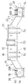
センタフレーム37の中央部はサイドフレーム38よりも高い位置に配置されており、前記脚部C1(センタフレーム37の外側部)は、図6に示すように、左右方向方に向かうにしたがって下方に移行する傾斜状に形成されている。
左右のサイドフレーム38は、図2、図5、図6に示すように、センタフレーム37の側方に配置されて脚部C1に連結された前後方向に長いメインフレーム59を備える。メインフレーム59の後端側に連結板60を介してモータケース61が後方突設され、メインフレーム59の前部側に連結板63を介してアイドラ保持部64が後方突設されている。
The center part of the center frame 37 is arranged at a position higher than the side frame 38, and the leg part C1 (outer part of the center frame 37) is lowered downward in the left-right direction as shown in FIG. It is formed in the shape of transition.
As shown in FIGS. 2, 5, and 6, the left and right side frames 38 include a main frame 59 that is disposed on the side of the center frame 37 and is connected to the leg portion C <b> 1 in the front-rear direction. A motor case 61 protrudes rearward from the rear end side of the main frame 59 via a connecting plate 60, and an idler holding portion 64 protrudes rearward from the front side of the main frame 59 via a connecting plate 63.

サイドフレーム38のメインフレーム59の上面は、センタフレーム37の外側部(脚部C1)の上面に連続するように、外側方に向けて徐々に下降するように傾斜されている。
サイドフレーム38(メインフレーム59)は、図7、図12に示すように、上壁72と、この上壁72の左右方向内端側から下方に延びる内側壁73と、上壁72の左右方向外端側から下方に延びる外側壁74とを備える断面門型に形成され、下端側が開口されている。
The upper surface of the main frame 59 of the side frame 38 is inclined so as to gradually descend outward so as to be continuous with the upper surface of the outer portion (leg portion C1) of the center frame 37.
As shown in FIGS. 7 and 12, the side frame 38 (main frame 59) includes an upper wall 72, an inner wall 73 extending downward from the inner end side in the left-right direction of the upper wall 72, and the left-right direction of the upper wall 72. It is formed in a cross-sectional gate shape including an outer wall 74 extending downward from the outer end side, and the lower end side is opened.

上壁72は左右方向外方に向かうにしたがって下方に移行する傾斜状に形成され、図6に示すように前記脚部C1上壁を構成する上部壁39B(板材)は、メインフレーム59の上壁72の内方側に重合されて溶接等によって固着されている。
図1、図3、図4に示すように、メインフレーム59の、内外側壁73,74間の下部に、前記転輪32が前後に間隔をおいて配置されていて、左右方向の軸心廻りに回動自在に支持されている。キャリアローラ33は、メインフレーム59の上壁72に左右方向の軸心廻りに回動自在に支持されている。
The upper wall 72 is formed in an inclined shape that moves downward as it goes outward in the left-right direction, and the upper wall 39B (plate material) that constitutes the upper wall of the leg portion C1, as shown in FIG. Polymerized on the inner side of the wall 72 and fixed by welding or the like.
As shown in FIGS. 1, 3, and 4, the rolling wheel 32 is disposed at a lower part of the main frame 59 between the inner and outer walls 73 and 74 with a space in the front and rear direction. It is rotatably supported by. The carrier roller 33 is supported on the upper wall 72 of the main frame 59 so as to be rotatable around a horizontal axis.

図2〜図5及び図6〜図9に示すように、アイドラ保持部64の上壁には、アイドラ31との干渉を避けるために、前方開放状で平面視U字形の切欠溝78が形成されており、アイドラ保持部64には、ヨーク86が前後方向摺動自在に支持されており、このヨーク86の前部にアイドラ31が左右方向の支軸87を介して回転自在に取り付けられ、アイドラ31はアイドラ保持部64の切欠溝78から上下及び前方に外方突出した状態に支持されている。
左右各メインフレーム59の前部には、クローラベルト34にテンションを与えるため及びそのテンションを調整するために、図2に示すテンション装置88が収納されている。
As shown in FIGS. 2 to 5 and FIGS. 6 to 9, a notch groove 78 having a front opening and a U-shape in plan view is formed on the upper wall of the idler holding portion 64 in order to avoid interference with the idler 31. A yoke 86 is supported on the idler holding portion 64 so as to be slidable in the front-rear direction. The idler 31 is rotatably attached to the front portion of the yoke 86 via a support shaft 87 in the left-right direction. The idler 31 is supported in a state in which the idler 31 protrudes outward from the cutout groove 78 of the idler holding portion 64 in the vertical and forward directions.
2 is housed in front portions of the left and right main frames 59 in order to apply tension to the crawler belt 34 and adjust the tension.

モータケース61は、左右方向内方側が開口した箱形に形成され、油圧モータMはモータケース61に取付用開口部68を介して内外突出状に支持されている。
モータケース61は、メインフレーム59よりも左右方向内方寄りに配置され、メインフレーム59の後端に、溶接、締結具その他の固定手段によって固定されている。その結果、モータケース61は、センタフレーム37の外側部の後端からサイドフレーム38のメインフレーム59の後端に亘って、後方突出状に取り付けられている。
前記モータケース61には駆動輪30を駆動する油圧モータMが左右方向外方に突出状に保持され、この突出部分に駆動輪30が取付固定されており、クローラベルト34は、サイドフレーム38を外囲いするように、駆動輪30,アイドラ31、転輪32及びキャリアローラ18に巻回されている。
The motor case 61 is formed in a box shape whose inner side in the left-right direction is open, and the hydraulic motor M is supported by the motor case 61 so as to project inward and outward through an attachment opening 68.
The motor case 61 is disposed inward in the left-right direction with respect to the main frame 59, and is fixed to the rear end of the main frame 59 by welding, a fastener, or other fixing means. As a result, the motor case 61 is attached in a protruding manner from the rear end of the outer portion of the center frame 37 to the rear end of the main frame 59 of the side frame 38.
A hydraulic motor M for driving the drive wheels 30 is held in the motor case 61 so as to protrude outward in the left-right direction. The drive wheels 30 are fixedly attached to the protruding portions, and the crawler belt 34 has a side frame 38 attached thereto. It is wound around the drive wheel 30, the idler 31, the roller wheel 32 and the carrier roller 18 so as to enclose it.

駆動輪30は、油圧モータMによって正逆転自在に回転駆動され、図1において、駆動輪30の反時計回りの回転によりクローラベルト34が反時計回りに循環回走してバックホー1が前進し、駆動輪30の時計回りの回転によりクローラベルト34が時計回りに循環回走してバックホー1が後進する。
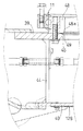
図3〜図5及び図12〜図14に示すように、サイドフレーム38(メインフレーム59)に、複数の転輪32が前後方向に間隔をおいて下方突出状に支持されている。転輪32を取り付ける取付板95は、転輪32に対応してサイドフレーム38の前後方向に複数設けられていて、サイドフレーム38の前後方向に互いに間隔をおいて断続的に配置されている。複数の取付板95は、前後方向の一端側が開口した嵌合凹部96を有する平面視コの字状に形成され、各取付板95は、サイドフレーム38の左右一対の側壁73,74の下端間を連結するように、サイドフレーム38に溶接等により装着(固定)されている。各取付板95の下面側に、転輪32を左右軸97廻りに回転自在に支持する支持体98がボルト等の固定具99により固定され、これにより、転輪32は嵌合凹部96から取付板95の上下に突出した状態で回転自在に支持されている。
The drive wheel 30 is rotationally driven by a hydraulic motor M so as to be able to rotate forward and backward. In FIG. 1, the crawler belt 34 circulates counterclockwise by the counterclockwise rotation of the drive wheel 30 and the backhoe 1 moves forward. The crawler belt 34 circulates in the clockwise direction by the clockwise rotation of the drive wheel 30 and the backhoe 1 moves backward.
As shown in FIG. 3 to FIG. 5 and FIG. 12 to FIG. A plurality of mounting plates 95 to which the wheel 32 is attached are provided in the front-rear direction of the side frame 38 corresponding to the wheel 32, and are intermittently arranged at intervals in the front-rear direction of the side frame 38. The plurality of mounting plates 95 are formed in a U shape having a fitting recess 96 opened at one end in the front-rear direction, and each mounting plate 95 is between the lower ends of the pair of left and right side walls 73, 74 of the side frame 38. Are attached (fixed) to the side frame 38 by welding or the like. On the lower surface side of each mounting plate 95, a support body 98 that supports the wheel 32 rotatably around the left and right axis 97 is fixed by a fixture 99 such as a bolt, whereby the wheel 32 is mounted from the fitting recess 96. The plate 95 is supported so as to be rotatable in a state of projecting up and down.

図15及び図16において、走行装置3の左側のクローラベルト34の前端側に、鉄製のクローラベルト34を回動不能にロックするロック機構100が設けられている。このロック機構100は、コの字状のロックプレート101とロックシャフト102と施錠具103とロックピン104とを備える。ロックプレート101は、左右一対の側板部105と、側板部105の前端部同士を左右に連結する連結板部106とを有するコの字状に形成され、一対の側板部105に挿通孔111が設けられている。ロックプレート101は、クローラベルト34の前端部の前側と左右外側とを囲むように、クローラベルト34の前端部側に配置されている。ロックプレート101の左右一対の側板部105間にロックシャフト102が連結されている。ロックシャフト102は、挿通孔111を通して一方(左側)の側板部105の外側方から他方の側板部105に向けて左右方向に挿通され、アイドラ31の貫通孔109を介してアイドラ31を左右に貫通して、他方(右側)の側板部105を貫通するように挿入され、その外方突出した挿入端部に取付孔107を介して施錠具103の施錠杆108が挿入され、この状態で施錠具103が施錠されている。これにより、他方の側板部105に対してロックシャフト102を施錠具103によって抜け止めしている。   15 and 16, a lock mechanism 100 that locks the iron crawler belt 34 so as not to rotate is provided on the front end side of the left crawler belt 34 of the traveling device 3. The lock mechanism 100 includes a U-shaped lock plate 101, a lock shaft 102, a locking tool 103, and a lock pin 104. The lock plate 101 is formed in a U shape having a pair of left and right side plate portions 105 and a connecting plate portion 106 that connects the front end portions of the side plate portions 105 to the left and right, and an insertion hole 111 is formed in the pair of side plate portions 105. Is provided. The lock plate 101 is disposed on the front end portion side of the crawler belt 34 so as to surround the front side of the front end portion and the left and right outer sides of the crawler belt 34. A lock shaft 102 is connected between a pair of left and right side plate portions 105 of the lock plate 101. The lock shaft 102 is inserted in the left-right direction from the outer side of one (left side) side plate part 105 through the insertion hole 111 toward the other side plate part 105, and penetrates the idler 31 left and right through the through hole 109 of the idler 31. Then, it is inserted so as to penetrate the other (right) side plate portion 105, and the locking rod 108 of the locking device 103 is inserted into the insertion end portion protruding outward from the insertion end 107, and in this state the locking device 103 is locked. As a result, the lock shaft 102 is prevented from coming off from the other side plate portion 105 by the lock 103.

ロックプレート101の連結板部106に、ロックピン104が突設されており、ロックピン104は、クローラベルト34の開口孔110に挿通され、前記ロックシャフト102が、一方の側板部105、アイドラ31及び他方の側板部105に挿通して施錠具103により抜け止めすることにより、ロックピン104は、クローラベルト34の開口孔110に挿通された状態に保持されるようになっている。これにより、ロック機構100によって左側のサイドフレーム38に対してクローラベルト34が回動不能になるようにロックされている。   A lock pin 104 protrudes from the connecting plate portion 106 of the lock plate 101, and the lock pin 104 is inserted into the opening hole 110 of the crawler belt 34, and the lock shaft 102 includes one side plate portion 105 and an idler 31. The lock pin 104 is held in a state of being inserted through the opening hole 110 of the crawler belt 34 by being inserted into the other side plate portion 105 and prevented from being removed by the locking device 103. Thereby, the crawler belt 34 is locked by the lock mechanism 100 so as not to rotate with respect to the left side frame 38.

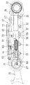
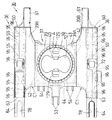
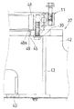
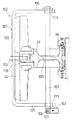
図2、図4、図5、図8及び図9において、走行装置3の走行フレーム27の旋回軸心X上に、ロータリジョイント117が設けられている。このロータリジョイント117の上端が上板39の開口46を介して旋回体2側に突出されている。ロータリジョイント117は、筒形のアウタースリーブ119と、このアウタースリーブ119に回動自在に挿入されるインナーシャフト120とから構成され、これらの内部に複数の油路が形成されている。
また、インナーシャフト120の頭部は旋回体3内に突出するとともに、旋回体3内の油圧ポンプからの油圧配管が制御弁を介して接続され、アウタースリーブ119の外周面には、接続口を介して左右の走行モータMやドーザシリンダ55等からの油圧ホース125が接続されている。
In FIGS. 2, 4, 5, 8, and 9, a rotary joint 117 is provided on the turning axis X of the traveling frame 27 of the traveling device 3. The upper end of the rotary joint 117 protrudes toward the revolving structure 2 through the opening 46 of the upper plate 39. The rotary joint 117 includes a cylindrical outer sleeve 119 and an inner shaft 120 that is rotatably inserted into the outer sleeve 119, and a plurality of oil passages are formed therein.
Further, the head of the inner shaft 120 protrudes into the swing body 3, and hydraulic piping from the hydraulic pump in the swing body 3 is connected via a control valve. A connection port is provided on the outer peripheral surface of the outer sleeve 119. The hydraulic hoses 125 from the left and right traveling motors M, the dozer cylinder 55, and the like are connected to each other.

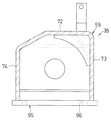
センタフレーム37の底板40には、センタフレーム37内の点検等に用いられる開口127が形成され、底板40に、前記開口127を下側から塞ぐようにカバー体128が着脱自在に取り付けられ、走行フレーム27の底板40に、前後一対の支持ステー129が上方突設されている。この一対の支持ステー129は、ロータリジョイント117の前後に配置されている。各支持ステー129は、コの字状の固定部130と該固定部130からL字状に上方突出したロータリジョイント取付部131とを有し、固定部130は底板40の開口127の前後に溶接又はボルト等の固定具により取り付けられている。ロータリジョイント117の上下方向中央部が、前記左右一対の支持ステー129を介して走行フレーム27の底板40に取り付けられている。   The bottom plate 40 of the center frame 37 is formed with an opening 127 used for inspection in the center frame 37, and a cover body 128 is detachably attached to the bottom plate 40 so as to close the opening 127 from below. A pair of front and rear support stays 129 protrudes upward from the bottom plate 40 of the frame 27. The pair of support stays 129 are disposed before and after the rotary joint 117. Each support stay 129 has a U-shaped fixing portion 130 and a rotary joint mounting portion 131 protruding upward in an L shape from the fixing portion 130, and the fixing portion 130 is welded before and after the opening 127 of the bottom plate 40. Or it is attached with fixing tools, such as a volt | bolt. A central portion of the rotary joint 117 in the vertical direction is attached to the bottom plate 40 of the traveling frame 27 via the pair of left and right support stays 129.

前記ロータリジョイント117の各支持ステー129への取付部135は、ロータリジョイント117の上下方向中央部の前後に、互いに上下にずらされて配置されている。前記ロータリジョイント117の前後に、側面視L字状の取付部材132が設けられている。この取付部材132は支持ステー129に対応して前後一対設けられ、一対の取付部材132の上部(一片)は、ボルト等の固定具133によりロータリジョイント117の一対の取付部135にそれぞれ固定されている。各取付部材132の(下部)他片は、各支持ステー129のロータリジョイント取付部131の水平な上部に、それぞれ載置してボルト等の固定具137により固定されている。   The attachment portions 135 of the rotary joint 117 to the respective support stays 129 are disposed so as to be vertically shifted from each other before and after the central portion of the rotary joint 117 in the vertical direction. Front and rear of the rotary joint 117 are provided with attachment members 132 that are L-shaped in side view. A pair of front and rear mounting members 132 are provided corresponding to the support stays 129, and upper portions (one piece) of the pair of mounting members 132 are respectively fixed to a pair of mounting portions 135 of the rotary joint 117 by a fixing member 133 such as a bolt. Yes. The other part (lower part) of each attachment member 132 is placed on the horizontal upper part of the rotary joint attachment part 131 of each support stay 129 and fixed by a fixture 137 such as a bolt.

上記実施の形態によれば、バックホー1を盗難防止するには、図15及び図16に示すように、ロックプレート101を、走行装置3のクローラベルト34の前端部の前側と左右外側とを囲むように、クローラベルト34の前端部側に配置して、ロックピン104を、クローラベルト34の開口孔110に挿通し、その後、ロックシャフト102を、一方の側板部105の外側方から他方の側板部105に向けて左右方向に挿通し、アイドラ31を左右に貫通して、他方の側板部105を貫通するように挿入し、その外方突出した挿入端部に取付孔107を介して施錠具103の施錠杆108を挿入し、この状態で施錠具103を施錠すればよい。これにより、サイドフレーム38に対してクローラベルト34が回動不能になるように簡単にロックされ、バックホー1の盗難防止が図られる。   According to the above embodiment, in order to prevent the backhoe 1 from being stolen, as shown in FIGS. 15 and 16, the lock plate 101 is surrounded by the front side of the front end portion of the crawler belt 34 of the traveling device 3 and the left and right outer sides. In this way, the lock pin 104 is inserted into the opening hole 110 of the crawler belt 34 and disposed on the front end side of the crawler belt 34, and then the lock shaft 102 is moved from the outer side of the one side plate portion 105 to the other side plate. It is inserted in the left-right direction toward the part 105, penetrates through the idler 31 left and right, and penetrates through the other side plate part 105, and is locked to the insertion end part protruding outward through the attachment hole 107. The locking rod 108 of 103 is inserted, and the locking tool 103 may be locked in this state. Thereby, the crawler belt 34 is easily locked with respect to the side frame 38 so that the crawler belt 34 cannot rotate, and the backhoe 1 can be prevented from being stolen.

そして、ロック機構100のロックを解除するには、ロックシャフト102の挿入端部から施錠具103を取り外し、その後、ロックシャフト102を、一方の側板部105側に引いて、他方の側板部105、アイドラ31及び一方の側板部105側から抜き取って、その後、ロックプレート101を、前方に引っ張って、ロックピン104をクローラベルト34の開口孔110から抜けばよく、ロック機構100によるロックを簡単に外すことができる。
また、転輪32を取り付けるための取付板95がサイドフレーム38の前後方向に互いに間隔をおいて断続的に配置されているため、各取付板95は小型で軽量になって、各取付板95の製造が容易になるし、全ての取付板95の合計の重量も、複数の転輪32に対して一体型のものとされていた従来の取付板に比べて相当軽くなり、取付板95は取り扱いやすくサイドフレーム38への装着も簡単になる。また、転輪32に対応する嵌合凹部96も各々別個の取付板95に形成されるため、嵌合凹部96同士の間隔の調整も容易になし得、このため、転輪32のピッチ寸法も精度が出し易くなり、この点からも取付板95のサイドフレーム38への装着が容易になる。
In order to unlock the lock mechanism 100, the locking device 103 is removed from the insertion end of the lock shaft 102, and then the lock shaft 102 is pulled toward one side plate portion 105, and the other side plate portion 105, After pulling out from the idler 31 and one side plate part 105 side, the lock plate 101 can be pulled forward and the lock pin 104 can be removed from the opening hole 110 of the crawler belt 34, and the lock by the lock mechanism 100 can be easily removed. be able to.
Further, since the mounting plates 95 for mounting the rolling wheels 32 are intermittently arranged at intervals in the front-rear direction of the side frame 38, the mounting plates 95 are small and light weight. The total weight of all the mounting plates 95 is considerably lighter than that of the conventional mounting plate that is integrated with the plurality of rolling wheels 32. Easy to handle and easy to attach to the side frame 38. In addition, since the fitting recesses 96 corresponding to the rolling wheels 32 are also formed on the separate mounting plates 95, the interval between the fitting recesses 96 can be easily adjusted. From this point, the mounting plate 95 can be easily attached to the side frame 38.

また、ロータリジョイント117の上下方向中央部が、前記支持ステー129を介して走行フレーム27の底板40に取り付けられているので、ロータリジョイント117に回動トルクがかかると、この回動トルクが、ロータリジョイント117に対して上下方向中央部を支点に揺動させるように作用することになり、このため、ロータリージョイント117の底面側乃至上端側が揺動する大きさを半減することができ、この点からロータリージョイント117の揺動をうまく抑制することができる。また、このため、走行フレーム27の底板40のロータリジョイント117支持部分や支持ステー129等に大きな強度を持たせる必要もなくなった。また、支持ステー129は、ロータリジョイント117の前後に一対設けられ、各支持ステー129へのロータリジョイント117の取付部135は、互いに上下にずらされているので、ロータリージョイント117が特定位置を支点に揺動するのを効果的に防止することができ、この点からも、ロータリージョイント117の揺動を抑制することができる。また、ボルト等の固定具が緩んでも、ロータリジョイント117が回動トルクによって大きく揺動しなくなり、これによってロータリジョイント117に連結した油圧ホース125が破損するのを防止できるようになる。   In addition, since the central portion of the rotary joint 117 in the vertical direction is attached to the bottom plate 40 of the traveling frame 27 via the support stay 129, when the rotational torque is applied to the rotary joint 117, the rotational torque is The joint 117 acts so that the central portion in the vertical direction is swung about the fulcrum, so that the magnitude of the swing of the bottom surface side to the upper end side of the rotary joint 117 can be halved. The swing of the rotary joint 117 can be suppressed well. For this reason, it is no longer necessary to give the rotary joint 117 supporting portion of the bottom plate 40 of the traveling frame 27, the support stay 129, etc. high strength. Also, a pair of support stays 129 are provided in front of and behind the rotary joint 117, and the attachment portions 135 of the rotary joint 117 to the respective support stays 129 are shifted up and down with respect to each other. Oscillation can be effectively prevented, and also from this point, oscillation of the rotary joint 117 can be suppressed. In addition, even if a fixture such as a bolt is loosened, the rotary joint 117 does not swing greatly due to the rotational torque, thereby preventing the hydraulic hose 125 connected to the rotary joint 117 from being damaged.

図17は他の実施形態を示し、クローラベルト34を、図15に示す鉄製に代えてゴム製のものを使用したものである。その他の点は前記実施の形態の場合と同様の構成である。
図18は他の実施形態を示し、開口46の内周面が、旋回ベアリング11のインナーギヤ68の歯底縁48aよりも径方向内方に突出するように配置されると共に、開口46の内周面の上端側に、インナーギヤ68の歯底縁直下から開口46の内方に向けて下降傾斜した土だまり防止面49が形成されている。その他の点は、前記実施形態の場合と同様の構成である。この場合も、旋回ベアリング11のインナーギヤ68側から落下した土は、上板39の開口46縁部上に落ちることなく、土だまり防止面49を滑り落ちて、開口46から落下するため、土が上板39の開口46縁部上に貯まることがなくなる。
FIG. 17 shows another embodiment in which the crawler belt 34 is made of rubber instead of the iron shown in FIG. The other points are the same as those in the above embodiment.
FIG. 18 shows another embodiment, in which the inner peripheral surface of the opening 46 is arranged so as to protrude radially inward from the root edge 48a of the inner gear 68 of the slewing bearing 11, and On the upper end side of the circumferential surface, an accumulation preventing surface 49 is formed that is inclined downward from directly below the tooth bottom edge of the inner gear 68 toward the inside of the opening 46. The other points are the same as those in the above embodiment. Also in this case, the soil that has fallen from the inner gear 68 side of the slewing bearing 11 does not fall on the edge of the opening 46 of the upper plate 39, but slides down the accumulation prevention surface 49 and falls from the opening 46. Will not accumulate on the edge of the opening 46 of the upper plate 39.

本願発明の一実施の形態を示すバックホーの側面図である。It is a side view of the backhoe which shows one embodiment of the invention in this application. 同バックホーの旋回台の平面図である。It is a top view of the swivel of the backhoe. 同バックホーの旋回台の側面断面図である。It is side surface sectional drawing of the swivel of the backhoe. 同バックホーの旋回台の他の側面断面図である。It is other side surface sectional drawing of the swivel of the backhoe. 同バックホーの走行フレームの平面図である。It is a top view of the traveling frame of the backhoe. 同バックホーの走行フレームの正面図である。It is a front view of the traveling frame of the backhoe. 同バックホーの走行フレームの側面図である。It is a side view of the traveling frame of the backhoe. 同ロータリジョイント部分の側面図である。It is a side view of the rotary joint part. 同ロータリジョイント部分の平面図である。It is a top view of the rotary joint part. 同センタフレーム前部の側断面図である。It is side sectional drawing of the center frame front part. 同センタフレーム後部の側断面図である。It is side sectional drawing of the center frame rear part. 同図7のA−A線断面図である。It is the sectional view on the AA line of the same FIG. 同転輪部分の側面図である。It is a side view of the same wheel part. 同他の転輪部分の側面図である。It is a side view of the other wheel part. 同ロック機構部分の平面断面図である。It is a plane sectional view of the lock mechanism part. 同ロック機構部分の側面図である。It is a side view of the lock mechanism part. 他の実施形態を示すロック機構部分の平面断面図である。It is a plane sectional view of a lock mechanism portion showing other embodiments. 他の実施形態を示すセンタフレーム前部の上端部分の側断面図である。It is side sectional drawing of the upper end part of the center frame front part which shows other embodiment.

符号の説明Explanation of symbols

1 バックホー
2 旋回体
3 走行装置
27 走行フレーム
32 転輪
38 サイドフレーム
39 上板
40 底板
73 内側壁
74 外側壁
95 取付板
96 嵌合凹部
97 左右軸
117 ロータリジョイント
129 支持ステー
132 取付部材
135 取付部
DESCRIPTION OF SYMBOLS 1 Backhoe 2 Revolving body 3 Traveling apparatus 27 Traveling frame 32 Rolling wheel 38 Side frame 39 Top plate 40 Bottom plate 73 Inner side wall 74 Outer side wall 95 Mounting plate 96 Fitting recessed part 97 Right and left shaft 117 Rotary joint 129 Support stay 132 Mounting member 135 Mounting part

Claims (3)

作業装置(7)を備えた旋回体(2)を、走行装置(3)上に上下方向の旋回軸心(X)回りに回動自在に備え、走行装置(3)の走行フレーム(27)の旋回軸心X上に、ロータリジョイント(117)が取り付けられた旋回作業機におけるロータリジョイントの取付構造において、
走行フレーム(27)の底板(40)に支持ステー(129)が上方突設され、ロータリジョイント(117)の上下方向中央部が、前記支持ステー(129)を介して走行フレーム(27)の底板(40)に取り付けられ
前記支持ステー(129)はロータリジョイント(117)に対して一対設けられ、各支持ステー(129)へのロータリジョイント(117)の取付部(135)は、互いに上下にずらされていることを特徴とする旋回作業機におけるロータリジョイントの取付構造。
A revolving body (2) provided with a work device (7) is provided on a traveling device (3) so as to be rotatable about a vertical pivot axis (X), and a traveling frame (27) of the traveling device (3). In the rotary joint mounting structure in the swing working machine in which the rotary joint (117) is mounted on the swing axis X of
A support stay (129) is provided on the bottom plate (40) of the traveling frame (27) so as to project upward, and the center portion in the vertical direction of the rotary joint (117) is interposed between the bottom plate of the traveling frame (27) and the support stay (129). Attached to (40) ,
A pair of the support stays (129) is provided with respect to the rotary joint (117), and the mounting portion (135) of the rotary joint (117) to each support stay (129) is shifted up and down. The rotary joint mounting structure in the swing work machine.
前記支持ステー(129)は、ロータリジョイント(117)の前後に一対設けられていることを特徴とする請求項1に記載の旋回作業機におけるロータリジョイントの取付構造。 It said support stay (129) is mounted structure of the rotary joint in rotary working machine according to claim 1, characterized in that is a pair provided et the front and rear of the rotary joint (117). 前記ロータリジョイント(117)に、側面視L字状の取付部材(132)が設けられ、このL字状の取付部材(132)の一片が、ロータリジョイント(117)側に固定され、取付部材(132)の他片が、前記支持ステー(129)のロータリジョイント取付部(131)に、載置して固定されていることを特徴とする請求項1又は2に記載の旋回作業機におけるロータリジョイントの取付構造。   The rotary joint (117) is provided with an L-shaped attachment member (132) in a side view, and a piece of the L-shaped attachment member (132) is fixed to the rotary joint (117) side, and the attachment member ( 132) The rotary joint in the swivel working machine according to claim 1 or 2, wherein the other piece is mounted and fixed to the rotary joint mounting portion (131) of the support stay (129). Mounting structure.
JP2004136553A 2004-04-30 2004-04-30 Mounting structure of rotary joint on turning work machine Expired - Lifetime JP4236609B2 (en)

Priority Applications (1)

Application Number Priority Date Filing Date Title
JP2004136553A JP4236609B2 (en) 2004-04-30 2004-04-30 Mounting structure of rotary joint on turning work machine

Applications Claiming Priority (1)

Application Number Priority Date Filing Date Title
JP2004136553A JP4236609B2 (en) 2004-04-30 2004-04-30 Mounting structure of rotary joint on turning work machine

Publications (3)

Publication Number Publication Date
JP2005315027A JP2005315027A (en) 2005-11-10
JP2005315027A5 JP2005315027A5 (en) 2007-11-08
JP4236609B2 true JP4236609B2 (en) 2009-03-11

Family

ID=35442737

Family Applications (1)

Application Number Title Priority Date Filing Date
JP2004136553A Expired - Lifetime JP4236609B2 (en) 2004-04-30 2004-04-30 Mounting structure of rotary joint on turning work machine

Country Status (1)

Country Link
JP (1) JP4236609B2 (en)

Cited By (1)

* Cited by examiner, † Cited by third party
Publication number Priority date Publication date Assignee Title
CN102888871A (en) * 2012-11-06 2013-01-23 淄博大力矿山机械有限公司 Rock loading machine of automatic rotating device with rotary central shaft

Cited By (1)

* Cited by examiner, † Cited by third party
Publication number Priority date Publication date Assignee Title
CN102888871A (en) * 2012-11-06 2013-01-23 淄博大力矿山机械有限公司 Rock loading machine of automatic rotating device with rotary central shaft

Also Published As

Publication number Publication date
JP2005315027A (en) 2005-11-10

Similar Documents

Publication Publication Date Title
KR20070109906A (en) Construction machine
WO2009017076A1 (en) Construction machine
JP4236645B2 (en) Mounting structure of rotary joint on turning work machine
JP4236609B2 (en) Mounting structure of rotary joint on turning work machine
JP2005313836A (en) Mounting structure of wheel in working vehicle
JP2011074605A (en) Crawler type traveling device
JP2008214887A (en) Construction machine
JP3808733B2 (en) Crawler type traveling device
JP2003328383A (en) Boom for drilling device
JP3660538B2 (en) Mounting structure of rotary joint in turning work machine
JP3615479B2 (en) Swivel work machine
JP7147622B2 (en) construction machinery
JP2003056005A (en) Crawler type travelling equipment
JP2019044425A (en) Work vehicle
JP2019203333A (en) Construction machine
JP7345536B2 (en) working machine
JP5124503B2 (en) Cover device for swivel work machine
JP7374031B2 (en) working machine
JP4633028B2 (en) Carrier roller support structure of crawler type traveling device
JP3611997B2 (en) Mounting structure of rotary joint in turning work machine
JP4675925B2 (en) Tractor frame structure
JP4693734B2 (en) Crawler type traveling device
JP3917356B2 (en) Crawler type traveling device
JP2020147909A (en) Construction machine
JP2005163533A (en) Working machine

Legal Events

Date Code Title Description
A621 Written request for application examination

Free format text: JAPANESE INTERMEDIATE CODE: A621

Effective date: 20060926

A521 Written amendment

Free format text: JAPANESE INTERMEDIATE CODE: A523

Effective date: 20070921

A977 Report on retrieval

Free format text: JAPANESE INTERMEDIATE CODE: A971007

Effective date: 20080411

A131 Notification of reasons for refusal

Free format text: JAPANESE INTERMEDIATE CODE: A131

Effective date: 20080422

A521 Written amendment

Free format text: JAPANESE INTERMEDIATE CODE: A523

Effective date: 20080619

TRDD Decision of grant or rejection written
A01 Written decision to grant a patent or to grant a registration (utility model)

Free format text: JAPANESE INTERMEDIATE CODE: A01

Effective date: 20081216

A01 Written decision to grant a patent or to grant a registration (utility model)

Free format text: JAPANESE INTERMEDIATE CODE: A01

A61 First payment of annual fees (during grant procedure)

Free format text: JAPANESE INTERMEDIATE CODE: A61

Effective date: 20081216

R150 Certificate of patent or registration of utility model

Ref document number: 4236609

Country of ref document: JP

Free format text: JAPANESE INTERMEDIATE CODE: R150

Free format text: JAPANESE INTERMEDIATE CODE: R150

FPAY Renewal fee payment (event date is renewal date of database)

Free format text: PAYMENT UNTIL: 20111226

Year of fee payment: 3

FPAY Renewal fee payment (event date is renewal date of database)

Free format text: PAYMENT UNTIL: 20121226

Year of fee payment: 4

FPAY Renewal fee payment (event date is renewal date of database)

Free format text: PAYMENT UNTIL: 20131226

Year of fee payment: 5