JP7345536B2 - working machine - Google Patents

working machine Download PDF

Info

Publication number
JP7345536B2
JP7345536B2 JP2021197392A JP2021197392A JP7345536B2 JP 7345536 B2 JP7345536 B2 JP 7345536B2 JP 2021197392 A JP2021197392 A JP 2021197392A JP 2021197392 A JP2021197392 A JP 2021197392A JP 7345536 B2 JP7345536 B2 JP 7345536B2
Authority
JP
Japan
Prior art keywords
counterweight
cylinder
sprocket
top cover
attachment
Prior art date
Legal status (The legal status is an assumption and is not a legal conclusion. Google has not performed a legal analysis and makes no representation as to the accuracy of the status listed.)
Active
Application number
JP2021197392A
Other languages
Japanese (ja)
Other versions
JP2023083170A (en
Inventor
裕洋 持丸
Current Assignee (The listed assignees may be inaccurate. Google has not performed a legal analysis and makes no representation or warranty as to the accuracy of the list.)
Komatsu Ltd
Original Assignee
Komatsu Ltd
Priority date (The priority date is an assumption and is not a legal conclusion. Google has not performed a legal analysis and makes no representation as to the accuracy of the date listed.)
Filing date
Publication date
Application filed by Komatsu Ltd filed Critical Komatsu Ltd
Priority to JP2021197392A priority Critical patent/JP7345536B2/en
Priority to PCT/JP2022/042422 priority patent/WO2023100645A1/en
Publication of JP2023083170A publication Critical patent/JP2023083170A/en
Application granted granted Critical
Publication of JP7345536B2 publication Critical patent/JP7345536B2/en
Active legal-status Critical Current
Anticipated expiration legal-status Critical

Links

Images

Classifications

    • EFIXED CONSTRUCTIONS
    • E02HYDRAULIC ENGINEERING; FOUNDATIONS; SOIL SHIFTING
    • E02FDREDGING; SOIL-SHIFTING
    • E02F9/00Component parts of dredgers or soil-shifting machines, not restricted to one of the kinds covered by groups E02F3/00 - E02F7/00
    • E02F9/18Counterweights

Description

本発明は、作業機械に関する。 TECHNICAL FIELD The present invention relates to working machines.

作業機械の一例である油圧ショベルには、カウンタウエイトが装着されている。大型の油圧ショベルでは、輸送規制にあわせるためにカウンタウエイトが車両本体に対して着脱可能に構成されている(例えば、特許文献1参照)。 A hydraulic excavator, which is an example of a working machine, is equipped with a counterweight. In large hydraulic excavators, a counterweight is configured to be detachable from the vehicle body in order to comply with transportation regulations (for example, see Patent Document 1).

特許文献1に示す油圧ショベルには、カウンタウエイトを車両本体に着脱するために着脱装置が設けられている。カウンタウエイトを車両本体に装着した状態では、着脱装置は、カウンタウエイトの切り欠き形状部分である収納部に配置される。この切り欠き形状部分の開口から土砂等が入り込むことを防ぐために上面カバーが設けられている。上面カバーは、車両本体にヒンジによって開閉可能に取り付けられており、着脱装置の上下方向への伸縮によって自動で開閉する。 The hydraulic excavator disclosed in Patent Document 1 is provided with an attachment/detachment device for attaching and detaching the counterweight to the vehicle body. When the counterweight is mounted on the vehicle body, the attachment/detachment device is disposed in a storage portion that is a cutout-shaped portion of the counterweight. A top cover is provided to prevent earth and sand from entering through the opening of this notch-shaped portion. The top cover is attached to the vehicle body with a hinge so that it can be opened and closed, and is automatically opened and closed by vertical expansion and contraction of the attachment/detachment device.

特開平11-1940号公報Japanese Patent Application Publication No. 11-1940

しかしながら、特許文献1の構成では、油圧ショベルの動作による振動によって上面カバーがヒンジを中心に振動するため、バタ付きが発生し、雨水・土砂等が入り込むおそれがある。 However, in the configuration of Patent Document 1, the top cover vibrates around the hinge due to vibrations caused by the operation of the hydraulic excavator, which may cause flapping and the possibility of rainwater, dirt, etc. entering.

本開示は、カウンタウエイトに形成された開口からの雨水・土砂等の侵入を抑制することが可能な作業機械を提供することを目的とする。 An object of the present disclosure is to provide a working machine that can suppress intrusion of rainwater, earth and sand through an opening formed in a counterweight.

本開示の第1の態様にかかる作業機械は、車両本体と、カウンタウエイトと、アクチュエータと、上面カバーと、を備える。カウンタウエイトは、車両本体に着脱可能である。アクチュエータは、車両本体にカウンタウエイトが装着された状態においてカウンタウエイトに形成された収納部に配置され、車両本体にカウンタウエイトを着脱する際に収納部の上方の開口を通して上下方向に伸縮する。上面カバーは、着脱装置の上側に取り付けられ、着脱装置の伸縮に伴って上下方向に移動し、最低位置で開口を塞ぐ。 A working machine according to a first aspect of the present disclosure includes a vehicle body, a counterweight, an actuator, and a top cover. The counterweight is removable from the vehicle body. The actuator is disposed in a storage section formed in the counterweight when the counterweight is attached to the vehicle body, and expands and contracts in the vertical direction through the upper opening of the storage section when the counterweight is attached to and removed from the vehicle body. The top cover is attached above the attachment/detachment device, moves vertically as the attachment/detachment device expands and contracts, and closes the opening at the lowest position.

本開示の態様によれば、カウンタウエイトに形成された開口からの雨水・土砂等の侵入を抑制することが可能な作業機械を提供することができる。 According to the aspect of the present disclosure, it is possible to provide a working machine that can suppress intrusion of rainwater, earth and sand through an opening formed in a counterweight.

本開示の実施形態にかかる油圧ショベルを示す斜視図である。1 is a perspective view showing a hydraulic excavator according to an embodiment of the present disclosure. 本開示の実施形態にかかる油圧ショベルにおいて旋回体のフレーム、カウンタウエイト、および着脱装置を前方から視た斜視図平面図である。FIG. 2 is a perspective plan view of a frame, a counterweight, and an attachment/detachment device of a revolving body viewed from the front in a hydraulic excavator according to an embodiment of the present disclosure. 本開示の実施形態にかかる油圧ショベルにおいてカウンタウエイトを旋回体のフレームから離間した状態を示す斜視図である。FIG. 2 is a perspective view showing a state in which the counterweight is separated from the frame of the rotating body in the hydraulic excavator according to the embodiment of the present disclosure. 本開示の実施形態にかかる油圧ショベルにおいてカウンタウエイトを旋回体のフレームから離間した状態を示す斜視図である。FIG. 2 is a perspective view showing a state in which the counterweight is separated from the frame of the rotating body in the hydraulic excavator according to the embodiment of the present disclosure. (a)本開示の実施形態にかかる油圧ショベルの着脱装置および上面カバーを示す斜視図である、(b)スプロケットの変形例を示す斜視図である。(a) It is a perspective view which shows the attachment/detachment device of the hydraulic excavator and a top cover concerning embodiment of this indication, (b) It is a perspective view which shows the modification of a sprocket. 図2の状態からシリンダを伸長した状態を示す斜視図である。FIG. 3 is a perspective view showing a state in which the cylinder is extended from the state in FIG. 2; 本開示の実施形態にかかる油圧ショベルにおける旋回体とカウンタウエイトへのチェーンの接続を説明するための斜視図であるIt is a perspective view for explaining connection of a chain to a revolving body and a counterweight in a hydraulic excavator according to an embodiment of the present disclosure. 本開示の実施形態にかかる油圧ショベルにおける車両本体側から視た着脱装置の上部分および上面カバーを示す図である。FIG. 2 is a diagram showing an upper portion and a top cover of the attachment/detachment device in the hydraulic excavator according to the embodiment of the present disclosure, as seen from the vehicle main body side. 図8Aに示す着脱装置の上部分を左側方から視た図である。FIG. 8B is a left side view of the upper portion of the attachment/detachment device shown in FIG. 8A; 本開示の実施形態にかかる油圧ショベルにおける車両本体側から視た脱着装置の上部分示す断面図である。FIG. 2 is a cross-sectional view showing the upper part of the attachment/detachment device in the hydraulic excavator according to the embodiment of the present disclosure, viewed from the vehicle main body side. 本開示の実施形態にかかる油圧ショベルにおける着脱装置の上部分および上面カバーを示す斜視図である。FIG. 2 is a perspective view showing an upper portion and a top cover of the attachment/detachment device in the hydraulic excavator according to the embodiment of the present disclosure. 本開示の実施形態にかかる油圧ショベルにおいてカウンタウエイトが車両本体に取り付けられた状態を示す断面図である。1 is a cross-sectional view showing a state in which a counterweight is attached to a vehicle body in a hydraulic excavator according to an embodiment of the present disclosure. 図9に示す状態からシリンダを伸長した状態を示す断面図である。10 is a sectional view showing a state in which the cylinder is extended from the state shown in FIG. 9. FIG. 図10Aの状態の旋回体全体を示す斜視図である。FIG. 10A is a perspective view showing the entire rotating structure in the state shown in FIG. 10A. 図10Aに示す状態からシリンダを収縮してカウンタウエイトを下方に移動させた状態を示す断面図である。10A is a sectional view showing a state in which the cylinder is contracted and the counterweight is moved downward from the state shown in FIG. 10A. FIG. 図10Aの状態の旋回体全体を示す斜視図である。FIG. 10A is a perspective view showing the entire rotating structure in the state shown in FIG. 10A. (a)、(b)本開示の実施形態の油圧ショベルにおけるショルダーボルトに配置されているスプリングの機能を説明するための模式図である。(a), (b) It is a schematic diagram for demonstrating the function of the spring arrange|positioned at the shoulder bolt in the hydraulic excavator of embodiment of this disclosure.

本開示にかかる作業機械の一例としての油圧ショベルについて図面を参照しながら以下に説明する。 A hydraulic excavator as an example of a working machine according to the present disclosure will be described below with reference to the drawings.

<構成>
(油圧ショベル1の概要)
図1は、本実施の形態の油圧ショベル1の構成を示す模式図である。
<Configuration>
(Overview of hydraulic excavator 1)
FIG. 1 is a schematic diagram showing the configuration of a hydraulic excavator 1 according to the present embodiment.

油圧ショベル1(作業機械の一例)は、車両本体2と、カウンタウエイト3と、着脱装置4(図2参照)と、上面カバー5と、を有する。車両本体2は、図1に示すように、走行体11と、旋回体12と、作業機13と、を有している。走行体11は、一対の走行装置11a、11bを有する。各走行装置11a、11bは、履帯11c、11dを有している。エンジンからの駆動力によって走行モータが回転して履帯11c、11dが駆動されることによって油圧ショベル1が走行する。 The hydraulic excavator 1 (an example of a working machine) includes a vehicle body 2, a counterweight 3, an attachment/detachment device 4 (see FIG. 2), and a top cover 5. As shown in FIG. 1, the vehicle main body 2 includes a traveling body 11, a revolving body 12, and a working machine 13. The traveling body 11 has a pair of traveling devices 11a and 11b. Each traveling device 11a, 11b has crawler belts 11c, 11d. The hydraulic excavator 1 travels by rotating the travel motor by the driving force from the engine and driving the tracks 11c and 11d.

旋回体12は、走行体11上に載置されている。旋回体12は、図示しない旋回装置によって上下方向に沿った軸を中心として走行体11に対して旋回可能に構成されている。旋回体12の前部左側位置には、オペレータが運転時に着座する運転席としてのキャブ14が設けられている。キャブ14の内部には、運転席、作業機13を操作するためのレバー、各種の表示装置等が配置されている。キャブ14の後方には、エンジンを収納するエンジンルーム15が配置されている。 The revolving body 12 is placed on the traveling body 11. The revolving body 12 is configured to be able to rotate relative to the traveling body 11 about an axis along the vertical direction by a rotating device (not shown). A cab 14 is provided at the front left side of the revolving structure 12 as a driver's seat where an operator sits during operation. Inside the cab 14, a driver's seat, levers for operating the work implement 13, various display devices, etc. are arranged. An engine room 15 for storing an engine is arranged behind the cab 14.

尚、本実施の形態において断りなき場合、前後左右はキャブ14内の運転席を基準として説明する。運転席が正面に正対する方向を前方向(矢印Xf参照)とし、前方向に対向する方向を後方向(矢印Xb参照)とする。運転席が正面に正対したときの側方方向の右側、左側をそれぞれ右方向(矢印Yr参照)、左方向(矢印Yl参照)とする。また、本明細書において「上下方向」は、特段記載のない限り、油圧ショベル1が傾斜せずに水平な状態での方向を示している。 In this embodiment, unless otherwise specified, front, rear, left and right will be described with reference to the driver's seat inside the cab 14. The direction in which the driver's seat faces the front is defined as the front direction (see arrow Xf), and the direction facing the front direction is defined as the rear direction (see arrow Xb). The right side and the left side in the lateral direction when the driver's seat faces the front are respectively defined as the right direction (see arrow Yr) and the left direction (see arrow Yl). Furthermore, in this specification, the term "vertical direction" refers to a direction when the hydraulic excavator 1 is in a horizontal state without being tilted, unless otherwise specified.

作業機13は、旋回体12の前部中央位置に取り付けられている。作業機13は、図1に示すように、ブーム21、アーム22、掘削バケット23を有する。ブーム21の基端部は、旋回体12に回動可能に連結されている。また、ブーム21の先端部はアーム22の基端部に回動可能に連結されている。アーム22の先端部は、掘削バケット23に回動可能に連結されている。掘削バケット23は、その開口が旋回体12の方向(後方)を向くことができるようにアーム22に取り付けられている。掘削バケット23が、このような向きに取り付けられた油圧ショベル1は、バックホウと呼ばれている。 The working machine 13 is attached to the front central position of the revolving body 12. The work machine 13 has a boom 21, an arm 22, and an excavation bucket 23, as shown in FIG. A base end portion of the boom 21 is rotatably connected to the revolving body 12. Further, the distal end of the boom 21 is rotatably connected to the base end of the arm 22. The tip of the arm 22 is rotatably connected to the excavation bucket 23. The excavation bucket 23 is attached to the arm 22 so that its opening can face toward the rotating body 12 (rearward). The hydraulic excavator 1 with the excavation bucket 23 attached in this orientation is called a backhoe.

ブーム21、アーム22および掘削バケット23のそれぞれに対応するように油圧シリンダ24~26(ブームシリンダ24、アームシリンダ25およびバケットシリンダ26)が配置されている。これらの油圧シリンダ24~26が駆動されることによって作業機13が駆動される。これにより、掘削等の作業が行われる。 Hydraulic cylinders 24 to 26 (boom cylinder 24, arm cylinder 25, and bucket cylinder 26) are arranged to correspond to boom 21, arm 22, and excavation bucket 23, respectively. The working machine 13 is driven by driving these hydraulic cylinders 24 to 26. As a result, work such as excavation is performed.

カウンタウエイト3は、車両本体2の後側に装着されている。カウンタウエイト3は、車両本体2に対して着脱可能である。詳しくは後述するが、着脱装置4は、カウンタウエイト3を車両本体2に着脱する。 The counterweight 3 is attached to the rear side of the vehicle body 2. The counterweight 3 is removable from the vehicle body 2. As will be described in detail later, the attachment/detachment device 4 attaches and detaches the counterweight 3 to and from the vehicle body 2.

(カウンタウエイト3)
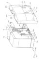
図2は、旋回体12のフレーム12aとカウンタウエイト3と着脱装置4を前方から視た斜視図である。図3は、カウンタウエイト3を旋回体12のフレーム12aから離間した状態を左後方から視た斜視図である。図4は、フレーム12aからカウンタウエイト3を離間した状態を前上方から視た斜視図である。
(Counterweight 3)
FIG. 2 is a perspective view of the frame 12a, counterweight 3, and attachment/detachment device 4 of the revolving body 12, viewed from the front. FIG. 3 is a perspective view of the counterweight 3 separated from the frame 12a of the rotating body 12, viewed from the left rear. FIG. 4 is a perspective view of the counterweight 3 separated from the frame 12a, viewed from the front and upper side.

カウンタウエイト3は、旋回体12のフレーム12aのうち後部のフレーム部分12bに取り付けられる。フレーム部分12bは、前後方向に対して垂直な板状の部分である。 The counterweight 3 is attached to a rear frame portion 12b of the frame 12a of the revolving body 12. The frame portion 12b is a plate-shaped portion perpendicular to the front-rear direction.

カウンタウエイト3には、前後方向に貫通した貫通孔31が複数個形成されている。図3に示すように、本実施の形態では、6つの貫通孔31がカウンタウエイト3に形成されている。6つの貫通孔31は、上下方向に沿って並んだ3つの貫通孔31の組が左右方向に並んで2組設けられている。フレーム部分12bには、各々の貫通孔31に対応する位置にボルトの挿入孔12cが形成されている。後方から貫通孔31を通して挿入孔12cにボルトを挿入することによって、カウンタウエイト3はフレーム部分12bに固定されている。なお、図3では、挿入孔12cは、左側面側の3つのみ図示されており、右側面側の3つの挿入孔12cは、着脱装置4によって隠れているため図示されていない。 The counterweight 3 is formed with a plurality of through holes 31 that penetrate in the front-rear direction. As shown in FIG. 3, six through holes 31 are formed in the counterweight 3 in this embodiment. The six through holes 31 are provided such that two sets of three through holes 31 are arranged in the vertical direction and are arranged in the left and right direction. Bolt insertion holes 12c are formed in the frame portion 12b at positions corresponding to the respective through holes 31. The counterweight 3 is fixed to the frame portion 12b by inserting a bolt into the insertion hole 12c through the through hole 31 from the rear. In addition, in FIG. 3, only the three insertion holes 12c on the left side are shown, and the three insertion holes 12c on the right side are hidden by the attachment/detachment device 4 and are therefore not shown.

図4に示すように、カウンタウエイト3には、上下方向に沿って凹部32(収納部の一例)が形成されている。凹部32によって、カウンタウエイト3に切り欠き形状部分が形成される。カウンタウエイト3を車両本体2に装着した状態では、図2に示すように、凹部32に、着脱装置4が配置される。凹部32は、カウンタウエイト3の上面33から下面まで形成されている。上面33には、図3および図4に示すように、凹部32による開口32aが形成されている。開口32aは、上面カバー5によって塞がれる。 As shown in FIG. 4, a recess 32 (an example of a storage section) is formed in the counterweight 3 along the vertical direction. The recess 32 forms a notch-shaped portion in the counterweight 3. When the counterweight 3 is attached to the vehicle body 2, the attachment/detachment device 4 is disposed in the recess 32, as shown in FIG. The recess 32 is formed from the upper surface 33 of the counterweight 3 to the lower surface. As shown in FIGS. 3 and 4, an opening 32a formed by the recess 32 is formed in the upper surface 33. As shown in FIGS. The opening 32a is closed by the top cover 5.

また、図4に示すように、カウンタウエイト3の前側の面のうち凹部32の最後部に対応する面部分32bには、上下方向に沿った板状のブラケット34が2つ配置されている。ブラケット34には、後述するチェーン44の端部44bが接続される。 Further, as shown in FIG. 4, two plate-shaped brackets 34 extending in the vertical direction are arranged on a surface portion 32b of the front surface of the counterweight 3 corresponding to the rearmost portion of the recess 32. An end portion 44b of a chain 44, which will be described later, is connected to the bracket 34.

(着脱装置4)
着脱装置4は、図5(a)に示すように車両本体2の後側に配置されている。着脱装置4の上側に上面カバー5は配置されている。
(Detachable device 4)
The attachment/detachment device 4 is arranged on the rear side of the vehicle main body 2, as shown in FIG. 5(a). A top cover 5 is arranged above the attachment/detachment device 4.

図5(a)は、着脱装置4を示す斜視図である。 FIG. 5(a) is a perspective view showing the attachment/detachment device 4. FIG.

着脱装置4は、図2に示すように、シリンダ41と、軸部材42と、スプロケット43と、チェーン44と、支持台45と、スプロケットカバー46(固定部の一例)と、ショルダーボルト47(支持部材の一例)と、スプリング48((弾性部材の一例)図8C参照)と、を備える。 As shown in FIG. 2, the attachment/detachment device 4 includes a cylinder 41, a shaft member 42, a sprocket 43, a chain 44, a support base 45, a sprocket cover 46 (an example of a fixed part), and a shoulder bolt 47 (supporting part). (an example of a member) and a spring 48 ((an example of an elastic member) see FIG. 8C).

シリンダ41は、図3に示すように、旋回体12の後部のフレーム部分12bに取り付けられている。フレーム部分12bは、前後方向に対して垂直な板状の部分である。フレーム部分12bの後面にシリンダ41が固定されている。シリンダ41は、上下方向に沿って配置されている。 The cylinder 41 is attached to the rear frame portion 12b of the revolving body 12, as shown in FIG. The frame portion 12b is a plate-shaped portion perpendicular to the front-rear direction. A cylinder 41 is fixed to the rear surface of the frame portion 12b. The cylinders 41 are arranged along the vertical direction.

詳細には、シリンダ41は、図5(a)に示すように、シリンダチューブ41aと、シリンダロッド41bと、を有する。シリンダチューブ41aは、上下方向に沿って配置されている。シリンダチューブ41aは、フレーム部分12bの後面に固定されている。シリンダロッド41bの下端には、図示しないピストンが配置されている。ピストンは、シリンダチューブ41a内に移動可能に配置されている。シリンダロッド41bの上端は、シリンダチューブ41aから上方に突出している。ピストンによってシリンダチューブ41aの内部空間は、ボトム側の空間とロッド側の空間に分けられる。 Specifically, as shown in FIG. 5(a), the cylinder 41 includes a cylinder tube 41a and a cylinder rod 41b. The cylinder tube 41a is arranged along the vertical direction. Cylinder tube 41a is fixed to the rear surface of frame portion 12b. A piston (not shown) is arranged at the lower end of the cylinder rod 41b. The piston is movably arranged within the cylinder tube 41a. The upper end of the cylinder rod 41b projects upward from the cylinder tube 41a. The internal space of the cylinder tube 41a is divided into a bottom side space and a rod side space by the piston.

図6は、図2の状態からシリンダ41を伸長した状態を示す図である。図示しないポンプによってシリンダチューブ41aのボトム側の空間に作動油を供給し、ロッド側の空間から作動油を排出することによってシリンダロッド41bがシリンダチューブ41aに対して上方に移動する。これによって、図6に示すようにシリンダ41が伸長する。 FIG. 6 is a diagram showing a state in which the cylinder 41 is extended from the state shown in FIG. A pump (not shown) supplies hydraulic oil to the space on the bottom side of the cylinder tube 41a, and discharges the hydraulic oil from the space on the rod side, thereby moving the cylinder rod 41b upward with respect to the cylinder tube 41a. This causes the cylinder 41 to expand as shown in FIG.

また、シリンダチューブ41aのボトム側の空間から作動油を排出し、ロッド側の空間に作動油を供給することによってシリンダロッド41bがシリンダチューブ41aに対して下方に移動する。これによって、図2に示すようにシリンダ41が収縮する。 Further, by discharging hydraulic oil from the space on the bottom side of the cylinder tube 41a and supplying hydraulic oil to the space on the rod side, the cylinder rod 41b moves downward with respect to the cylinder tube 41a. This causes the cylinder 41 to contract as shown in FIG.

軸部材42は、シリンダロッド41bの先端41cに固定されている。軸部材42は、左右方向に沿って配置されている。軸部材42は、先端41cから左方向側に突出し、先端41cから右方向側に突出している。 The shaft member 42 is fixed to the tip 41c of the cylinder rod 41b. The shaft member 42 is arranged along the left-right direction. The shaft member 42 projects leftward from the tip 41c, and projects rightward from the tip 41c.

図5(a)に示すように、スプロケット43は、シリンダロッド41bの先端41cの左側と右側の双方に配置されている。スプロケット43は、軸部材42に回転可能に配置されている。なお、本実施の形態では、スプロケット43には左右方向に沿って貫通孔が形成されており、その貫通孔に軸部材42が挿入されている。スプロケット43が軸部材42に対して回転すると、軸部材42の外周面とスプロケット43の貫通孔の内周面が摺動するが、このような構成に限らなくてもよい。例えば、図5(b)に示すように、スプロケット43に形成されている貫通孔43aの内側にベアリング143が圧入されていてもよい。ベアリング143は、軸部材42とスプロケット43の間に配置される。 As shown in FIG. 5(a), the sprocket 43 is arranged on both the left and right sides of the tip 41c of the cylinder rod 41b. The sprocket 43 is rotatably arranged on the shaft member 42. In this embodiment, a through hole is formed in the sprocket 43 along the left-right direction, and the shaft member 42 is inserted into the through hole. When the sprocket 43 rotates with respect to the shaft member 42, the outer peripheral surface of the shaft member 42 and the inner peripheral surface of the through hole of the sprocket 43 slide, but the structure is not limited to this. For example, as shown in FIG. 5(b), a bearing 143 may be press-fitted inside a through hole 43a formed in the sprocket 43. Bearing 143 is arranged between shaft member 42 and sprocket 43.

チェーン44は、スプロケット43に巻き掛けられている。チェーン44は、旋回体12とカウンタウエイト3に接続されている。左右方向におけるシリンダロッド41bの先端41cの両側にスプロケット43が配置されているため、チェーン44もシリンダロッド41bの先端41cの左右両側に配置されている。 The chain 44 is wound around the sprocket 43. The chain 44 is connected to the revolving body 12 and the counterweight 3. Since the sprockets 43 are arranged on both sides of the tip 41c of the cylinder rod 41b in the left-right direction, the chains 44 are also arranged on both the left and right sides of the tip 41c of the cylinder rod 41b.

図7は、旋回体12とカウンタウエイト3へのチェーン44の接続を説明するための斜視図である。図7では、チェーン44の両端を見やすくするためにシリンダ41を伸ばした状態を示す。また、チェーン44の紙面奥側の構造を示し、チェーン44は二点鎖線で示されている。 FIG. 7 is a perspective view for explaining the connection of the chain 44 to the revolving body 12 and the counterweight 3. As shown in FIG. In FIG. 7, the cylinder 41 is shown extended to make it easier to see both ends of the chain 44. Further, the structure of the chain 44 on the back side of the paper is shown, and the chain 44 is indicated by a chain double-dashed line.

左右の各々のチェーン44の一方の端部44aは、フレーム部分12bに接続されている。フレーム部分12bの後方側の面には、2つのブラケット12dが配置されている。各々のブラケット12dは後方に向かって突出した板状部分を有し、その板状部分は上下方向に沿って配置されている。各々のチェーン44の端部44aは、各々のブラケット12dの板状部分に左右方向に沿った軸を中心に回転可能に取り付けられている。 One end 44a of each of the left and right chains 44 is connected to the frame portion 12b. Two brackets 12d are arranged on the rear side surface of the frame portion 12b. Each bracket 12d has a plate-shaped portion that protrudes toward the rear, and the plate-shaped portion is arranged along the vertical direction. An end portion 44a of each chain 44 is rotatably attached to a plate-shaped portion of each bracket 12d about an axis along the left-right direction.

各々のチェーン44の他方の端部44bは、カウンタウエイト3の前側の面に接続されている。各々のチェーン44の端部44bは、上述した面部分32bに配置された各々のブラケット34に左右方向に沿った軸を中心に回転可能に取り付けられている。 The other end 44b of each chain 44 is connected to the front surface of the counterweight 3. The end portion 44b of each chain 44 is rotatably attached to each bracket 34 disposed on the above-mentioned surface portion 32b about an axis along the left-right direction.

図8Aは、車両本体2側から視た着脱装置4の上部分および上面カバー5を示す図である。図8Aは、シリンダ41が収縮して開口32aが上面カバー5によって塞がれている状態を示す。図8Bは、着脱装置4の上部分を左側方から視た図である。図8Cは、車両本体2側から視た着脱装置4の上部分を示す断面図である。図8Dは、着脱装置4の上部分および上面カバー5を示す斜視図である。 FIG. 8A is a diagram showing the upper portion of the attachment/detachment device 4 and the top cover 5 as viewed from the vehicle main body 2 side. FIG. 8A shows a state in which the cylinder 41 is contracted and the opening 32a is closed by the top cover 5. FIG. 8B is a diagram of the upper portion of the attachment/detachment device 4 viewed from the left side. FIG. 8C is a sectional view showing the upper part of the attachment/detachment device 4 viewed from the vehicle main body 2 side. FIG. 8D is a perspective view showing the upper portion of the attachment/detachment device 4 and the top cover 5. FIG.

支持台45は、図8Aに示すように、シリンダ41の先端41cに固定されている。支持台45は、先端41cの上側に配置されている。支持台45は、スプロケットカバー46を支持するために設けられている。 The support stand 45 is fixed to the tip 41c of the cylinder 41, as shown in FIG. 8A. The support stand 45 is arranged above the tip 41c. The support stand 45 is provided to support the sprocket cover 46.

スプロケットカバー46は、スプロケット43の上方を覆うように配置されている。スプロケットカバー46は、図8Aに示すように、支持台45の上側にボルト101によって固定されている。スプロケットカバー46は、図8Cに示すように、スプロケット43の上方を覆う上面部46aと、上面部46aの左右の端から下方に延びる縁部46bと、を有する。上面部46aとスプロケット43との間の隙間と、縁部46bとスプロケット43との間の隙間は、チェーン44が通過できないような大きさに形成されている。 The sprocket cover 46 is arranged to cover the upper part of the sprocket 43. The sprocket cover 46 is fixed to the upper side of the support base 45 with bolts 101, as shown in FIG. 8A. As shown in FIG. 8C, the sprocket cover 46 has an upper surface portion 46a that covers above the sprocket 43, and edges 46b that extend downward from the left and right ends of the upper surface portion 46a. The gap between the upper surface portion 46a and the sprocket 43 and the gap between the edge portion 46b and the sprocket 43 are formed to a size such that the chain 44 cannot pass through.

ショルダーボルト47は、スプロケットカバー46の上面部46aの上側に配置されている。ショルダーボルト47は、例えば4つ配置されている。各々のショルダーボルト47は、上下方向に沿って配置されている。図8Aおよび図8Bに示すように、4本のショルダーボルト47が配置されている。4本のショルダーボルト47は、左右方向に2つ並んだ組が前後方向に並んで2組配置されている。上面部46aには、ショルダーボルト47を固定する台座46cが配置されている。台座46cは、左右方向に並んで2つ配置されており、左側の台座46cには、左側の2つのショルダーボルト47が固定され、右側の台座46cには、右側の2つのショルダーボルト47が固定されている。 The shoulder bolt 47 is arranged above the upper surface portion 46a of the sprocket cover 46. For example, four shoulder bolts 47 are arranged. Each shoulder bolt 47 is arranged along the vertical direction. As shown in FIGS. 8A and 8B, four shoulder bolts 47 are arranged. The four shoulder bolts 47 are arranged in two sets, with two sets lined up in the left-right direction, and two sets lined up in the front-rear direction. A pedestal 46c to which a shoulder bolt 47 is fixed is arranged on the upper surface portion 46a. Two pedestals 46c are arranged side by side in the left-right direction, and two left shoulder bolts 47 are fixed to the left pedestal 46c, and two right shoulder bolts 47 are fixed to the right pedestal 46c. has been done.

ショルダーボルト47は、棒状部47a(貫通部の一例)とヘッド部47bとを有する。棒状部47aは、下端が台座46cに固定されている。ヘッド部47bは、棒状部47aの上端に配置されている。ヘッド部47bの外径は棒状部47aの外径よりも大きく形成されている。4つのショルダーボルト47のヘッド部47bの上側には、上面カバー5が載置されている。 The shoulder bolt 47 has a rod-shaped portion 47a (an example of a penetrating portion) and a head portion 47b. The lower end of the rod-shaped portion 47a is fixed to the base 46c. The head portion 47b is arranged at the upper end of the rod-shaped portion 47a. The outer diameter of the head portion 47b is larger than the outer diameter of the rod-shaped portion 47a. The top cover 5 is placed above the head portions 47b of the four shoulder bolts 47.

スプリング48は、図8Cに示すように、各々のショルダーボルト47の周囲に配置されている。スプリング48にはショルダーボルト47の棒状部47aが通っている。スプリング48は、上面カバー5のスプリング支持部53の平面部533(後述する)とヘッド部47bの間に配置されている。 A spring 48 is disposed around each shoulder bolt 47, as shown in FIG. 8C. A rod-shaped portion 47a of the shoulder bolt 47 passes through the spring 48. The spring 48 is disposed between a flat portion 533 (described later) of the spring support portion 53 of the top cover 5 and the head portion 47b.

(上面カバー5)
上面カバー5は、上述したように着脱装置4の上側に配置されている。上面カバー5は、シリンダ41の伸縮とともに上下方向に移動する。
(Top cover 5)
The top cover 5 is arranged above the attachment/detachment device 4 as described above. The top cover 5 moves in the vertical direction as the cylinder 41 expands and contracts.

上面カバー5は、シリンダ41が収縮した際に、図8Aに示すように、カウンタウエイト3の上面33に当接し、凹部32の開口32aを塞ぐことが出来る。 When the cylinder 41 contracts, the top cover 5 can come into contact with the top surface 33 of the counterweight 3 and close the opening 32a of the recess 32, as shown in FIG. 8A.

上面カバー5は、図8Aに示すように、カバー本体51と、弾性部材52と、スプリング支持部53と、を有している。カバー本体51は、板形状である。カバー本体51は、カウンタウエイト3の上面33に形成されている開口32aよりも若干大きく形成されている。カバー本体51は矩形状である。カバー本体51の矩形状の2組の辺のうち一方の組の各々の辺は、左右方向に沿って配置されている。矩形状の2組の辺のうち他方の組の各々の辺は、前後方向に沿って配置されている。これら全ての辺は、下方に向かって折れ曲げられている。 As shown in FIG. 8A, the top cover 5 includes a cover body 51, an elastic member 52, and a spring support portion 53. The cover body 51 has a plate shape. The cover main body 51 is formed slightly larger than the opening 32a formed in the upper surface 33 of the counterweight 3. The cover body 51 has a rectangular shape. Each side of one set of the two sets of rectangular sides of the cover main body 51 is arranged along the left-right direction. Of the two sets of rectangular sides, each side of the other set is arranged along the front-rear direction. All these edges are bent downward.

弾性部材52は、例えばゴムによって形成されている。弾性部材52は、図8Bおよび図8Cに示すように、カバー本体51の上面33と接する面51dの端部に配置されている。弾性部材52は、図8Dに示すカバー本体51の後側の辺51aと、左側の辺51bと、右側の辺51cの夫々に沿って配置されている。弾性部材52は、図8Bに示すように、取付部521と、緩衝部522と、を有する。取付部521は、カバー本体51の縁に取り付けられる部分である。カバー本体51の下方に向かって折り曲げられた端に、取付部521を下方から差し込むことによって、カバー本体51に弾性部材52が取り付けられる。緩衝部522は、円筒状である。上面カバー5によって開口32aが閉じられる際、緩衝部522がカウンタウエイト3の開口32aの周囲の上面33に当接する。緩衝部522の円筒形状が潰れることによって、上面カバー5とカウンタウエイト3の上面33が密着し、雨水・土砂等の侵入を防ぐことができる。また、上面カバー5のバタつきを抑制できる。着脱装置4の収縮によって、上面カバー5は最低位置で開口32aを塞ぐが、最低位置は弾性部材52の潰し代分による上下位置の変動を含む。 The elastic member 52 is made of rubber, for example. As shown in FIGS. 8B and 8C, the elastic member 52 is disposed at the end of the surface 51d that is in contact with the top surface 33 of the cover body 51. The elastic member 52 is arranged along each of the rear side 51a, the left side 51b, and the right side 51c of the cover body 51 shown in FIG. 8D. The elastic member 52 has a mounting portion 521 and a buffer portion 522, as shown in FIG. 8B. The attachment portion 521 is a portion attached to the edge of the cover body 51. The elastic member 52 is attached to the cover body 51 by inserting the attachment portion 521 into the downwardly bent end of the cover body 51 from below. The buffer portion 522 has a cylindrical shape. When the opening 32a is closed by the top cover 5, the buffer portion 522 comes into contact with the top surface 33 of the counterweight 3 around the opening 32a. By collapsing the cylindrical shape of the buffer portion 522, the top cover 5 and the top surface 33 of the counterweight 3 are brought into close contact with each other, thereby preventing intrusion of rainwater, earth and sand, etc. Moreover, flapping of the top cover 5 can be suppressed. When the attachment/detachment device 4 contracts, the top cover 5 closes the opening 32a at the lowest position, but the lowest position includes fluctuations in the vertical position due to the crushing allowance of the elastic member 52.

スプリング支持部53は、図8Aに示すように、カバー本体51の下側に取り付けられている。スプリング支持部53は、板状の部材を折り曲げることによって形成することができる。スプリング支持部53は、U字形状を有する。スプリング支持部53は、左側面部531と、右側面部532と、平面部533と、を有する。 The spring support portion 53 is attached to the lower side of the cover body 51, as shown in FIG. 8A. The spring support portion 53 can be formed by bending a plate-like member. The spring support portion 53 has a U-shape. The spring support portion 53 has a left side surface portion 531, a right side surface portion 532, and a flat portion 533.

図8Cに示すように、左側面部531は、左側の2つのショルダーボルト47よりも左側に配置されている。左側面部531は、カバー本体51から下方に向かって突出している。左側面部531は、板状である。左側面部531は前後方向に沿って配置されている。右側面部532は、右側の2つのショルダーボルト47よりも右側に配置されている。右側面部532は、カバー本体51から下方に向かって突出している。右側面部532は、板状である。右側面部532は前後方向に沿って配置されている。 As shown in FIG. 8C, the left side portion 531 is disposed to the left of the two left shoulder bolts 47. The left side portion 531 projects downward from the cover body 51. The left side portion 531 is plate-shaped. The left side portion 531 is arranged along the front-rear direction. The right side portion 532 is located to the right of the two right shoulder bolts 47. The right side portion 532 projects downward from the cover body 51. The right side portion 532 is plate-shaped. The right side portion 532 is arranged along the front-rear direction.

平面部533は、左側面部531の下端と右側面部532の下端を繋ぐように配置されている。平面部533は、板状である。図8Cに示すように、平面部533は、上下方向に対して垂直に配置されている。平面部533には、上下方向に沿った貫通孔53aが4つ形成されている。各々の貫通孔にショルダーボルト47が通されている。 The plane part 533 is arranged to connect the lower end of the left side part 531 and the lower end of the right side part 532. The flat portion 533 is plate-shaped. As shown in FIG. 8C, the plane portion 533 is arranged perpendicularly to the up-down direction. Four through holes 53a are formed in the plane portion 533 along the vertical direction. A shoulder bolt 47 is passed through each through hole.

<動作>
次に、本実施の形態の油圧ショベル1におけるカウンタウエイト3の着脱動作について説明する。
<Operation>
Next, the operation of attaching and detaching the counterweight 3 in the hydraulic excavator 1 of this embodiment will be explained.

図9、図10A、図10B、図11Aおよび図11Bは、車両本体2からのカウンタウエイト3の取り外し動作を説明するための図である。 9, FIG. 10A, FIG. 10B, FIG. 11A, and FIG. 11B are diagrams for explaining the operation of removing the counterweight 3 from the vehicle body 2.

図9は、カウンタウエイト3が車両本体2に取り付けられており、カウンタウエイト3の上面33の開口32aが上面カバー5によって閉じられている状態を示す断面図である。図9に示す状態で、油圧ショベル1は駆動して作業等を行う。この状態では、チェーン44の余った部分は、フレーム部分12bの前側の面に配置されている収納ボックス49に収納されている。 FIG. 9 is a sectional view showing a state in which the counterweight 3 is attached to the vehicle body 2 and the opening 32a of the upper surface 33 of the counterweight 3 is closed by the upper surface cover 5. As shown in FIG. In the state shown in FIG. 9, the hydraulic excavator 1 is driven and performs work. In this state, the remaining portion of the chain 44 is stored in a storage box 49 arranged on the front surface of the frame portion 12b.

カウンタウエイト3を車両本体2から取り外す際には、図10Aに示すように、シリンダ41が伸長される。シリンダチューブ41aのボトム側の空間に作動油を供給し、ロッド側の空間から作動油を排出することによって、シリンダロッド41bがシリンダチューブ41aに対して上方に移動する。シリンダ41の伸長とともに、スプロケット43が回転しながらチェーン44が収納ボックス49から引き出される。図10Bは、シリンダ41が伸長した状態の車両本体2を示す斜視図である。 When removing the counterweight 3 from the vehicle body 2, the cylinder 41 is extended as shown in FIG. 10A. By supplying hydraulic oil to the space on the bottom side of the cylinder tube 41a and discharging the hydraulic oil from the space on the rod side, the cylinder rod 41b moves upward with respect to the cylinder tube 41a. As the cylinder 41 expands, the chain 44 is pulled out from the storage box 49 while the sprocket 43 rotates. FIG. 10B is a perspective view showing the vehicle body 2 with the cylinder 41 extended.

この状態で、カウンタウエイト3に設けられている貫通孔31に挿入されているボルトが取り外されて、カウンタウエイト3のフレーム部分12bとの締結が解除される。 In this state, the bolt inserted into the through hole 31 provided in the counterweight 3 is removed, and the fastening with the frame portion 12b of the counterweight 3 is released.

次に、図11Aに示すように、シリンダ41を収縮させる。シリンダチューブ41aのロッド側の空間に作動油を供給し、ボトム側の空間から作動油を排出することによって、シリンダロッド41bがシリンダチューブ41aに対して下方に移動する。シリンダ41の収縮とともに、スプロケット43が回転しながら、チェーン44の端部44bに接続されているカウンタウエイト3が下方に移動する。図11Bは、カウンタウエイト3が下方に移動して地面に接した状態の車両本体2を示す斜視図である。 Next, as shown in FIG. 11A, the cylinder 41 is contracted. By supplying hydraulic oil to the space on the rod side of the cylinder tube 41a and discharging the hydraulic oil from the space on the bottom side, the cylinder rod 41b moves downward with respect to the cylinder tube 41a. As the cylinder 41 contracts and the sprocket 43 rotates, the counterweight 3 connected to the end 44b of the chain 44 moves downward. FIG. 11B is a perspective view showing the vehicle body 2 in a state where the counterweight 3 has moved downward and is in contact with the ground.

次に、チェーン44の他方の端部44bとブラケット34の接続が解除される。これによって、カウンタウエイト3を車両本体2から取り外すことができる。 Next, the connection between the other end 44b of the chain 44 and the bracket 34 is released. Thereby, the counterweight 3 can be removed from the vehicle body 2.

なお、車両本体2にカウンタウエイト3を装着する際の動作は、概ね上記と逆の手順で行われる。 The operation for mounting the counterweight 3 on the vehicle body 2 is generally performed in the reverse order to the above.

図11Bに示すように、車両本体2の後側にカウンタウエイト3が配置される。そして、チェーン44の端部44bがカウンタウエイト3のブラケット34に接続される。 As shown in FIG. 11B, the counterweight 3 is arranged on the rear side of the vehicle body 2. Then, the end portion 44b of the chain 44 is connected to the bracket 34 of the counterweight 3.

次に、図10Aに示すように、シリンダ41が伸長されて、カウンタウエイト3が上方に引き上げられる。 Next, as shown in FIG. 10A, the cylinder 41 is extended and the counterweight 3 is pulled upward.

次に、後方から6つの貫通孔31の夫々を通して挿入孔12cにボルトを挿入し、カウンタウエイト3がフレーム部分12bに固定される。 Next, bolts are inserted from the rear into the insertion holes 12c through each of the six through holes 31, and the counterweight 3 is fixed to the frame portion 12b.

次に、図9に示すように、シリンダ41が収縮され、余ったチェーン44が自重によって収納ボックス49に収納され、上面カバー5がカウンタウエイト3の開口32aを塞ぐ。 Next, as shown in FIG. 9, the cylinder 41 is contracted, the excess chain 44 is stored in the storage box 49 by its own weight, and the top cover 5 closes the opening 32a of the counterweight 3.

ここで、ショルダーボルト47に配置されているスプリング48の機能について説明する。図12(a)および図12(b)は、ショルダーボルト47に配置されているスプリング48の機能を説明するための模式図である。 Here, the function of the spring 48 disposed on the shoulder bolt 47 will be explained. FIGS. 12(a) and 12(b) are schematic diagrams for explaining the function of the spring 48 disposed on the shoulder bolt 47. FIG.

図12(a)は、着脱装置4の上部および上面カバー5を示す模式図である。この状態からシリンダ41が収縮することによって上面カバー5がカウンタウエイト3の上面33に当接する。このとき、製造誤差等によって、シリンダ41が収縮した際の上面カバー5の高さ位置が、カウンタウエイト3の上面33の高さ位置とずれていても、スプリング48の潰し代によって吸収することができる。図12(b)に示すように、上面カバー5がカウンタウエイト3の上面33に当接してからも、スプリング48の潰し代分、ショルダーボルト47はシリンダロッド41bとともに下方に移動することができる。この際、図12(b)に示すように、ヘッド部47bとカバー本体51の間に隙間が生じることが可能である。このため、製造誤差によって上面カバー5の位置と上面33の位置がずれていたとしても、上面カバー5を上面33に密着させることができる。 FIG. 12A is a schematic diagram showing the upper part of the attachment/detachment device 4 and the top cover 5. FIG. As the cylinder 41 contracts from this state, the top cover 5 comes into contact with the top surface 33 of the counterweight 3. At this time, even if the height position of the top cover 5 when the cylinder 41 is contracted deviates from the height position of the top surface 33 of the counterweight 3 due to manufacturing errors, it can be absorbed by the crushing allowance of the spring 48. can. As shown in FIG. 12(b), even after the top cover 5 comes into contact with the top surface 33 of the counterweight 3, the shoulder bolt 47 can move downward together with the cylinder rod 41b by the amount of compression of the spring 48. At this time, as shown in FIG. 12(b), a gap may occur between the head portion 47b and the cover body 51. Therefore, even if the position of the top cover 5 and the position of the top surface 33 deviate due to manufacturing errors, the top cover 5 can be brought into close contact with the top surface 33.

<特徴等>
(1)
本実施の形態の油圧ショベル1(作業機械の一例)は、車両本体2と、カウンタウエイト3と、着脱装置4と、上面カバー5と、を備える。カウンタウエイト3は、車両本体2に着脱可能である。着脱装置4は、車両本体2にカウンタウエイト3が装着された状態においてカウンタウエイト3に形成された凹部32(収納部の一例)に配置され、車両本体2にカウンタウエイト3を着脱する際に凹部32の上方の開口32aを通して上下方向に伸縮する。上面カバー5は、着脱装置4に取り付けられ、着脱装置4の伸縮に伴って上下方向に移動し、最低位置で開口32aを塞ぐ。
<Features etc.>
(1)
The hydraulic excavator 1 (an example of a working machine) of the present embodiment includes a vehicle body 2, a counterweight 3, an attachment/detachment device 4, and a top cover 5. The counterweight 3 is removable from the vehicle body 2. The attachment/detachment device 4 is disposed in a recess 32 (an example of a storage portion) formed in the counterweight 3 when the counterweight 3 is attached to the vehicle body 2, and is inserted into the recess when the counterweight 3 is attached to or detached from the vehicle body 2. It expands and contracts in the vertical direction through the opening 32a above 32. The top cover 5 is attached to the attachment/detachment device 4, moves vertically as the attachment/detachment device 4 expands and contracts, and closes the opening 32a at the lowest position.

このように、上面カバー5を着脱装置4に取り付けることによって、上面カバー5によって開口32aが閉じられた状態において油圧ショベル1が動作した場合であっても着脱装置4の自重によって上面カバー5が振動し難くバタ付きが抑制される。 In this way, by attaching the top cover 5 to the attachment/detachment device 4, even if the hydraulic excavator 1 operates with the opening 32a closed by the top cover 5, the top cover 5 will not vibrate due to the weight of the attachment/detachment device 4. It is difficult to do so, and flapping is suppressed.

このため、着脱装置4の動作のためにカウンタウエイト3に形成された開口32aから雨水・土砂が浸入することを抑制することができる。 Therefore, it is possible to suppress rainwater and dirt from entering through the opening 32a formed in the counterweight 3 for the operation of the attachment/detachment device 4.

(2)
本実施の形態の油圧ショベル1では、着脱装置4は、シリンダ41を有する。シリンダ41は、上下方向に伸縮する。シリンダ41は、シリンダチューブ41aと、シリンダロッド41bとを含む。シリンダチューブ41aは、車両本体2に上下方向に沿って固定されている。シリンダロッド41bは、シリンダチューブ41aに対して上方に移動する。上面カバー5は、シリンダロッド41bの先端に取り付けられている。
(2)
In the hydraulic excavator 1 of this embodiment, the attachment/detachment device 4 has a cylinder 41. The cylinder 41 expands and contracts in the vertical direction. Cylinder 41 includes a cylinder tube 41a and a cylinder rod 41b. The cylinder tube 41a is fixed to the vehicle body 2 along the vertical direction. Cylinder rod 41b moves upward relative to cylinder tube 41a. The top cover 5 is attached to the tip of the cylinder rod 41b.

これにより、シリンダチューブ41aに対してシリンダロッド41bが下方に移動することによって、開口32aを上面カバー5で塞ぐことができる。また、シリンダ41を油圧で作動させた場合、シリンダ41が収縮した状態において下方に向かって作動油圧が生じているため、上面カバー5のバタつきをより抑制することができる。 Thereby, the cylinder rod 41b moves downward with respect to the cylinder tube 41a, so that the opening 32a can be closed with the top cover 5. Further, when the cylinder 41 is hydraulically operated, since the hydraulic pressure is generated downward in the contracted state of the cylinder 41, the flapping of the top cover 5 can be further suppressed.

(3)
本実施の形態の油圧ショベル1では、着脱装置4は、スプロケット43と、チェーン44を更に有する。スプロケット43は、シリンダロッド41bの先端に回転可能に配置されている。チェーン44は、車両本体2とカウンタウエイト3に接続されスプロケット43に巻き掛けられている。
(3)
In the hydraulic excavator 1 of this embodiment, the attachment/detachment device 4 further includes a sprocket 43 and a chain 44. The sprocket 43 is rotatably arranged at the tip of the cylinder rod 41b. The chain 44 is connected to the vehicle body 2 and the counterweight 3 and is wound around the sprocket 43.

これにより、シリンダ41の伸縮に伴ってチェーン44に接続されているカウンタウエイト3を上下方向に移動することができる。 Thereby, the counterweight 3 connected to the chain 44 can be moved in the vertical direction as the cylinder 41 expands and contracts.

(4)
本実施の形態の油圧ショベル1では、着脱装置4は、スプロケットカバー46を更に有する。スプロケットカバー46は、スプロケット43の上側を覆うようにシリンダロッド41bの先端に配置されている。上面カバー5は、スプロケットカバー46の上側に配置されており、スプロケットカバー46を介してシリンダロッド41bの先端に取り付けられている。
(4)
In the hydraulic excavator 1 of this embodiment, the attachment/detachment device 4 further includes a sprocket cover 46. The sprocket cover 46 is arranged at the tip of the cylinder rod 41b so as to cover the upper side of the sprocket 43. The top cover 5 is disposed above the sprocket cover 46, and is attached to the tip of the cylinder rod 41b via the sprocket cover 46.

スプロケット43を覆うスプロケットカバー46を設けることによって、シリンダ41の伸縮によってチェーン44のスプロケット43からの脱落を防止することができる。 By providing a sprocket cover 46 that covers the sprocket 43, it is possible to prevent the chain 44 from falling off the sprocket 43 due to expansion and contraction of the cylinder 41.

(5)
本実施の形態の油圧ショベル1では、着脱装置4は、ショルダーボルト47(支持部材の一例)と、スプロケットカバー46(固定部の一例)と、スプリング48(弾性部材の一例)と、スプリング支持部53(弾性部材支持部の一例)と、を有する。ショルダーボルト47は、棒状であり、上面カバー5の下側に配置され、上面カバー5を支持する。スプロケットカバー46は、ショルダーボルト47をシリンダロッド41bの先端に固定する。スプリング48は、ショルダーボルト47の周囲に配置されている。スプリング支持部53は、スプリング48を下方から支持し、ショルダーボルト47が通る貫通孔53aを有し、上面カバー5に固定されている。ショルダーボルト47は、棒状部47a(貫通部の一例)と、ヘッド部47bと、を有する。棒状部47aは、貫通孔53aを通る。ヘッド部47bは、棒状部47aの上側に配置されている。スプリング48は、ヘッド部47bとスプリング支持部53の間に配置されている。
(5)
In the hydraulic excavator 1 of the present embodiment, the attachment/detachment device 4 includes a shoulder bolt 47 (an example of a support member), a sprocket cover 46 (an example of a fixed part), a spring 48 (an example of an elastic member), and a spring support part. 53 (an example of an elastic member support part). The shoulder bolt 47 has a rod shape, is disposed below the top cover 5, and supports the top cover 5. Sprocket cover 46 fixes shoulder bolt 47 to the tip of cylinder rod 41b. Spring 48 is arranged around shoulder bolt 47. The spring support portion 53 supports the spring 48 from below, has a through hole 53a through which the shoulder bolt 47 passes, and is fixed to the top cover 5. The shoulder bolt 47 has a rod-shaped portion 47a (an example of a penetrating portion) and a head portion 47b. The rod-shaped portion 47a passes through the through hole 53a. The head portion 47b is arranged above the rod-shaped portion 47a. The spring 48 is arranged between the head portion 47b and the spring support portion 53.

これにより、スプリング48の潰し代を用いて、上面カバー5をカウンタウエイト3の上面33に密着させることができるため、雨水・土砂等の開口32aからの侵入をより確実に防止することができる。 Thereby, the upper surface cover 5 can be brought into close contact with the upper surface 33 of the counterweight 3 using the crushing margin of the spring 48, so that it is possible to more reliably prevent rainwater, dirt, etc. from entering through the opening 32a.

(6)
本実施の形態の油圧ショベル1では、着脱装置4は、軸部材42と、ベアリング143と、を更に有する。軸部材42は、シリンダロッド41bの先端に配置されている。ベアリング143は、軸部材42が通されるスプロケット43の貫通孔43aに圧入されている。
(6)
In the hydraulic excavator 1 of this embodiment, the attachment/detachment device 4 further includes a shaft member 42 and a bearing 143. The shaft member 42 is arranged at the tip of the cylinder rod 41b. The bearing 143 is press-fitted into a through hole 43a of the sprocket 43 through which the shaft member 42 is passed.

これにより、スプロケット43の軸部材42に対する摺動抵抗を低減することができるため、スプロケット43がスムーズに回転可能となり、チェーン44の格納性を向上することができる。
(7)
本実施の形態の油圧ショベル1では、カウンタウエイト3は、開口33aが形成された上面33を有する。上面カバー5は、上面33と接する面51dの端部に配置された弾性部材52を有する。
これによって、上面カバー5とカウンタウエイト3の上面33が密着し、雨水・土砂等の侵入を防ぐことができる。また、上面カバー5のバタつきを抑制できる。
Thereby, the sliding resistance of the sprocket 43 with respect to the shaft member 42 can be reduced, so that the sprocket 43 can rotate smoothly, and the retractability of the chain 44 can be improved.
(7)
In the hydraulic excavator 1 of this embodiment, the counterweight 3 has an upper surface 33 in which an opening 33a is formed. The top cover 5 has an elastic member 52 disposed at the end of a surface 51d in contact with the top surface 33.
As a result, the upper surface cover 5 and the upper surface 33 of the counterweight 3 come into close contact with each other, and it is possible to prevent rainwater, dirt, etc. from entering. Moreover, flapping of the top cover 5 can be suppressed.

(他の実施形態)
以上、本発明の一実施形態について説明したが、本発明は上記実施形態に限定されるものではなく、発明の要旨を逸脱しない範囲で種々の変更が可能である。
(Other embodiments)
Although one embodiment of the present invention has been described above, the present invention is not limited to the above embodiment, and various changes can be made without departing from the gist of the invention.

(A)
上記実施の形態では、着脱装置4の伸縮機構としてシリンダ41が用いられており、シリンダ41として油圧シリンダを例に挙げて説明しているが、これに限らなくてもよく、電動シリンダが用いられていてもよい。また、シリンダにかぎらなくてもよく、スライドして伸縮するようなアクチュエータが用いられてもよい。
(A)
In the above embodiment, the cylinder 41 is used as the expansion/contraction mechanism of the attachment/detachment device 4, and the explanation is given using a hydraulic cylinder as an example of the cylinder 41, but it is not limited to this, and an electric cylinder may be used. You can leave it there. Further, the actuator is not limited to a cylinder, and an actuator that slides and expands and contracts may be used.

(B)
上記実施の形態では、着脱装置4にスプロケット43およびチェーン44が用いられているが、これに限らなくてもよく、例えば滑車とワイヤー等が用いられてもよい。
(B)
In the above embodiment, the sprocket 43 and the chain 44 are used in the attachment/detachment device 4, but the attachment/detachment device 4 is not limited to this, and for example, a pulley, a wire, etc. may be used.

(C)
上記実施の形態では、スプロケットカバー46を介して上面カバー5がシリンダ41に取り付けられているが、スプロケットカバー46が設けられておらず、上面カバー5がシリンダ41に直接取り付けられていてもよい。
(C)
In the above embodiment, the top cover 5 is attached to the cylinder 41 via the sprocket cover 46, but the sprocket cover 46 may not be provided and the top cover 5 may be attached directly to the cylinder 41.

(D)
上記実施の形態では、作業機械の一例として油圧ショベルを用いて説明したが、これに限らなくてもよく、ホイールローダ等のカウンタウエイトが設けられている作業機械に適用することができる。
(D)
Although the above embodiment has been described using a hydraulic excavator as an example of a working machine, the invention is not limited to this, and can be applied to a working machine such as a wheel loader that is provided with a counterweight.

本開示によれば、カウンタウエイトに形成された開口からの雨水・土砂等の侵入を抑制することが可能な作業機械を提供することができ、油圧ショベル等に有用である。 According to the present disclosure, it is possible to provide a working machine that can suppress intrusion of rainwater, earth and sand through an opening formed in a counterweight, and is useful for hydraulic excavators and the like.

1:油圧ショベル、 2:車両本体、 3:カウンタウエイト、 4:着脱装置、 5:上面カバー、 11:走行体、 11a:走行装置、 11b:走行装置、 11c:履帯、 11d:履帯、 12:旋回体、 12a:フレーム、 12b:フレーム部分、 12c:挿入孔、12d:ブラケット、 13:作業機、 14:キャブ、 15:エンジンルーム、 21:ブーム、 22:アーム、 23:掘削バケット、 24:ブームシリンダ、 25:アームシリンダ、 26:バケットシリンダ、 31:貫通孔、 32:凹部、 32a:開口、 32b:面部分、 33:上面、 34:ブラケット、 41:シリンダ、 41a:シリンダチューブ、 41b:シリンダロッド、 41c:先端部、 42:軸部材、 43:スプロケット、 43a:貫通孔、 44:チェーン、 44a:端部、 44b:端部、 45:支持台、 46:スプロケットカバー、 46a:上面部、 46b:縁部、 46c:台座、 47:ショルダーボルト、 47a:棒状部、 47b:ヘッド部、 48:スプリング、 49:収納ボックス、 51:カバー本体、 51a:辺、 51b:辺、 51c:辺、 52:弾性部材、 53:スプリング支持部、 101:ボルト、 143:ベアリング、 521:取付部、 522:緩衝部、 531:左側面部、 532:右側面部、 533:平面部
DESCRIPTION OF SYMBOLS 1: Hydraulic excavator, 2: Vehicle main body, 3: Counterweight, 4: Attachment/detaching device, 5: Top cover, 11: Traveling body, 11a: Traveling device, 11b: Traveling device, 11c: Track, 11d: Track, 12: revolving body, 12a: frame, 12b: frame part, 12c: insertion hole, 12d: bracket, 13: work equipment, 14: cab, 15: engine room, 21: boom, 22: arm, 23: excavation bucket, 24: Boom cylinder, 25: Arm cylinder, 26: Bucket cylinder, 31: Through hole, 32: Recess, 32a: Opening, 32b: Surface portion, 33: Top surface, 34: Bracket, 41: Cylinder, 41a: Cylinder tube, 41b: Cylinder rod, 41c: Tip, 42: Shaft member, 43: Sprocket, 43a: Through hole, 44: Chain, 44a: End, 44b: End, 45: Support, 46: Sprocket cover, 46a: Top surface , 46b: edge, 46c: pedestal, 47: shoulder bolt, 47a: bar, 47b: head, 48: spring, 49: storage box, 51: cover body, 51a: side, 51b: side, 51c: side , 52: Elastic member, 53: Spring support part, 101: Bolt, 143: Bearing, 521: Mounting part, 522: Buffer part, 531: Left side part, 532: Right side part, 533: Plane part

Claims (7)

車両本体と、
前記車両本体に着脱可能なカウンタウエイトと、
前記車両本体に前記カウンタウエイトが装着された状態において前記カウンタウエイトに形成された収納部に配置され、前記車両本体に前記カウンタウエイトを着脱する際に前記収納部の上方の開口を通して上下方向に伸縮する着脱装置と、
前記着脱装置の上側に取り付けられ、前記着脱装置の伸縮に伴って上下方向に移動し、最低位置で前記開口を塞ぐ上面カバーと、を備えた、
作業機械。
The vehicle body,
a counterweight that is detachable from the vehicle body;
When the counterweight is attached to the vehicle body, it is disposed in a storage part formed in the counterweight, and when the counterweight is attached to or removed from the vehicle body, it expands and contracts in the vertical direction through an opening above the storage part. a detachable device for
a top cover that is attached to the upper side of the detachable device, moves in the vertical direction as the detachable device expands and contracts, and closes the opening at the lowest position;
working machine.
前記着脱装置は、
前記車両本体に上下方向に沿って固定されたシリンダチューブと、前記シリンダチューブに対して上方に移動するシリンダロッドと、を含み、上下方向に伸縮するシリンダを有し、
前記上面カバーは、前記シリンダロッドの先端に取り付けられている、
請求項1に記載の作業機械。
The attachment/detachment device is
The vehicle includes a cylinder tube fixed to the vehicle body along the vertical direction, and a cylinder rod that moves upward with respect to the cylinder tube, and has a cylinder that expands and contracts in the vertical direction,
The top cover is attached to the tip of the cylinder rod,
The working machine according to claim 1.
前記着脱装置は、
前記シリンダロッドの先端に回転可能に配置されたスプロケットと、
前記車両本体と前記カウンタウエイトに接続され前記スプロケットに巻き掛けられたチェーンと、を更に有する、
請求項2に記載の作業機械。
The attachment/detachment device is
a sprocket rotatably disposed at the tip of the cylinder rod;
further comprising a chain connected to the vehicle body and the counterweight and wrapped around the sprocket;
A working machine according to claim 2.
前記着脱装置は、
前記スプロケットの上側を覆うように前記シリンダロッドの先端に配置されたスプロケットカバーを更に有し、
前記上面カバーは、前記スプロケットカバーの上側に配置されており、前記スプロケットカバーを介して前記シリンダロッドの先端に取り付けられている、
請求項3に記載の作業機械。
The attachment/detachment device is
further comprising a sprocket cover disposed at the tip of the cylinder rod so as to cover the upper side of the sprocket;
The top cover is disposed above the sprocket cover, and is attached to the tip of the cylinder rod via the sprocket cover.
A working machine according to claim 3.
前記着脱装置は、
前記上面カバーの下側に配置され、前記上面カバーを支持する棒状の支持部材と、
前記支持部材を前記シリンダロッドの先端に固定する固定部と、
前記支持部材の周囲に配置された弾性部材と、
前記弾性部材を下方から支持し、前記支持部材が通る貫通孔を有し、前記上面カバーに固定された弾性部材支持部と、を有し、
前記支持部材は、前記貫通孔を通る貫通部と、前記貫通部の上側に配置されたヘッド部と、を有し、
前記弾性部材は、前記ヘッド部と前記弾性部材支持部の間に配置されている、
請求項2に記載の作業機械。
The attachment/detachment device is
a rod-shaped support member disposed below the top cover and supporting the top cover;
a fixing part that fixes the support member to the tip of the cylinder rod;
an elastic member disposed around the support member;
an elastic member support part that supports the elastic member from below, has a through hole through which the support member passes, and is fixed to the top cover;
The support member has a penetrating portion passing through the through hole, and a head portion disposed above the penetrating portion,
the elastic member is disposed between the head section and the elastic member support section;
A working machine according to claim 2.
前記着脱装置は、
前記シリンダロッドの先端に配置された軸部材と、
前記軸部材が通される前記スプロケットの貫通孔に圧入されたベアリングと、を更に有する、
請求項3に記載の作業機械。
The attachment/detachment device is
a shaft member disposed at the tip of the cylinder rod;
further comprising a bearing press-fitted into a through hole of the sprocket through which the shaft member is passed;
A working machine according to claim 3.
前記カウンタウエイトは、前記開口が形成された上面を有し、
前記上面カバーは、前記上面と接する面の端部に配置された弾性部材を有する、
請求項1に記載の作業機械。
The counterweight has an upper surface in which the opening is formed,
The top cover has an elastic member disposed at an end of a surface in contact with the top surface.
The working machine according to claim 1.
JP2021197392A 2021-12-03 2021-12-03 working machine Active JP7345536B2 (en)

Priority Applications (2)

Application Number Priority Date Filing Date Title
JP2021197392A JP7345536B2 (en) 2021-12-03 2021-12-03 working machine
PCT/JP2022/042422 WO2023100645A1 (en) 2021-12-03 2022-11-15 Work machine

Applications Claiming Priority (1)

Application Number Priority Date Filing Date Title
JP2021197392A JP7345536B2 (en) 2021-12-03 2021-12-03 working machine

Publications (2)

Publication Number Publication Date
JP2023083170A JP2023083170A (en) 2023-06-15
JP7345536B2 true JP7345536B2 (en) 2023-09-15

Family

ID=86612051

Family Applications (1)

Application Number Title Priority Date Filing Date
JP2021197392A Active JP7345536B2 (en) 2021-12-03 2021-12-03 working machine

Country Status (2)

Country Link
JP (1) JP7345536B2 (en)
WO (1) WO2023100645A1 (en)

Citations (5)

* Cited by examiner, † Cited by third party
Publication number Priority date Publication date Assignee Title
JP2002167807A (en) 2000-11-30 2002-06-11 Kobelco Contstruction Machinery Ltd Counter-weight disconnecting device
JP2011246926A (en) 2010-05-26 2011-12-08 Hitachi Constr Mach Co Ltd Counterweight attaching/detaching device of working machine
JP2019206807A (en) 2018-05-28 2019-12-05 日立建機株式会社 Work machine
JP2020143436A (en) 2019-03-04 2020-09-10 株式会社日立建機ティエラ Construction machine
JP7268908B2 (en) 2021-06-08 2023-05-08 全国農業協同組合連合会 Method for improving carcass performance of cattle after short-distance transportation

Family Cites Families (1)

* Cited by examiner, † Cited by third party
Publication number Priority date Publication date Assignee Title
JP2922778B2 (en) * 1994-03-29 1999-07-26 日立建機株式会社 Counterweight removal equipment for work equipment

Patent Citations (5)

* Cited by examiner, † Cited by third party
Publication number Priority date Publication date Assignee Title
JP2002167807A (en) 2000-11-30 2002-06-11 Kobelco Contstruction Machinery Ltd Counter-weight disconnecting device
JP2011246926A (en) 2010-05-26 2011-12-08 Hitachi Constr Mach Co Ltd Counterweight attaching/detaching device of working machine
JP2019206807A (en) 2018-05-28 2019-12-05 日立建機株式会社 Work machine
JP2020143436A (en) 2019-03-04 2020-09-10 株式会社日立建機ティエラ Construction machine
JP7268908B2 (en) 2021-06-08 2023-05-08 全国農業協同組合連合会 Method for improving carcass performance of cattle after short-distance transportation

Also Published As

Publication number Publication date
JP2023083170A (en) 2023-06-15
WO2023100645A1 (en) 2023-06-08

Similar Documents

Publication Publication Date Title
JP4544121B2 (en) Construction machinery
KR100693978B1 (en) Swiveling work machine
KR20070109906A (en) Construction machine
JP6340068B2 (en) Excavator
JP4920022B2 (en) Swivel construction machine
JP7345536B2 (en) working machine
JP3718434B2 (en) Cylinder protection device
WO2007105326A1 (en) Excavation machine
JP6346676B2 (en) Excavator
JP5296640B2 (en) Work vehicle and method for removing generator motor from work vehicle
JP7398422B2 (en) working machine
JP2010059681A (en) Loader work machine
JP4836849B2 (en) Work machine dozer equipment
JP4798985B2 (en) Swivel work machine
JP3820113B2 (en) Excavator
JP5507348B2 (en) Construction machinery
JP4583315B2 (en) Swivel work machine
JP4425061B2 (en) Dozer equipment
JP6595927B2 (en) Work vehicle
JP4381287B2 (en) Swivel work machine
JP4236609B2 (en) Mounting structure of rotary joint on turning work machine
JP4633028B2 (en) Carrier roller support structure of crawler type traveling device
JP4522298B2 (en) Swivel work machine
JP2022180239A (en) Construction machine
JP5153552B2 (en) Machine room of construction machinery

Legal Events

Date Code Title Description
A621 Written request for application examination

Free format text: JAPANESE INTERMEDIATE CODE: A621

Effective date: 20230112

TRDD Decision of grant or rejection written
A01 Written decision to grant a patent or to grant a registration (utility model)

Free format text: JAPANESE INTERMEDIATE CODE: A01

Effective date: 20230822

A61 First payment of annual fees (during grant procedure)

Free format text: JAPANESE INTERMEDIATE CODE: A61

Effective date: 20230905

R151 Written notification of patent or utility model registration

Ref document number: 7345536

Country of ref document: JP

Free format text: JAPANESE INTERMEDIATE CODE: R151