JP4223936B2 - Projection optical system, enlargement projection optical system, enlargement projection apparatus, and image projection apparatus - Google Patents
Projection optical system, enlargement projection optical system, enlargement projection apparatus, and image projection apparatus Download PDFInfo
- Publication number
- JP4223936B2 JP4223936B2 JP2003409304A JP2003409304A JP4223936B2 JP 4223936 B2 JP4223936 B2 JP 4223936B2 JP 2003409304 A JP2003409304 A JP 2003409304A JP 2003409304 A JP2003409304 A JP 2003409304A JP 4223936 B2 JP4223936 B2 JP 4223936B2
- Authority
- JP
- Japan
- Prior art keywords
- optical system
- projection
- image
- transmission
- refractive
- Prior art date
- Legal status (The legal status is an assumption and is not a legal conclusion. Google has not performed a legal analysis and makes no representation as to the accuracy of the status listed.)
- Expired - Lifetime
Links
- 230000003287 optical effect Effects 0.000 title claims description 648
- 230000005540 biological transmission Effects 0.000 claims description 106
- 238000003384 imaging method Methods 0.000 claims description 43
- 230000004075 alteration Effects 0.000 description 34
- 238000005286 illumination Methods 0.000 description 16
- 239000004973 liquid crystal related substance Substances 0.000 description 16
- 238000000034 method Methods 0.000 description 15
- 238000012937 correction Methods 0.000 description 12
- 238000013461 design Methods 0.000 description 12
- 230000000694 effects Effects 0.000 description 10
- 230000015572 biosynthetic process Effects 0.000 description 8
- 238000011144 upstream manufacturing Methods 0.000 description 8
- 230000009471 action Effects 0.000 description 7
- 230000004907 flux Effects 0.000 description 7
- 230000009467 reduction Effects 0.000 description 7
- 238000010586 diagram Methods 0.000 description 5
- 238000000926 separation method Methods 0.000 description 5
- 238000003491 array Methods 0.000 description 4
- 230000008859 change Effects 0.000 description 3
- 238000005457 optimization Methods 0.000 description 3
- 230000010287 polarization Effects 0.000 description 3
- 238000012545 processing Methods 0.000 description 3
- 210000001747 pupil Anatomy 0.000 description 3
- 238000003786 synthesis reaction Methods 0.000 description 3
- 239000002131 composite material Substances 0.000 description 2
- 239000006185 dispersion Substances 0.000 description 2
- 238000006073 displacement reaction Methods 0.000 description 2
- 238000011156 evaluation Methods 0.000 description 2
- 230000005484 gravity Effects 0.000 description 2
- 229910052736 halogen Inorganic materials 0.000 description 2
- 150000002367 halogens Chemical class 0.000 description 2
- 230000006872 improvement Effects 0.000 description 2
- 239000000463 material Substances 0.000 description 2
- QSHDDOUJBYECFT-UHFFFAOYSA-N mercury Chemical compound [Hg] QSHDDOUJBYECFT-UHFFFAOYSA-N 0.000 description 2
- 229910052753 mercury Inorganic materials 0.000 description 2
- 229910001507 metal halide Inorganic materials 0.000 description 2
- 150000005309 metal halides Chemical class 0.000 description 2
- 238000000465 moulding Methods 0.000 description 2
- 230000008569 process Effects 0.000 description 2
- 238000004088 simulation Methods 0.000 description 2
- 229910052724 xenon Inorganic materials 0.000 description 2
- FHNFHKCVQCLJFQ-UHFFFAOYSA-N xenon atom Chemical compound [Xe] FHNFHKCVQCLJFQ-UHFFFAOYSA-N 0.000 description 2
- 238000013459 approach Methods 0.000 description 1
- 238000005452 bending Methods 0.000 description 1
- 230000008901 benefit Effects 0.000 description 1
- 239000003086 colorant Substances 0.000 description 1
- 230000007423 decrease Effects 0.000 description 1
- 230000006866 deterioration Effects 0.000 description 1
- 230000003511 endothelial effect Effects 0.000 description 1
- 238000005516 engineering process Methods 0.000 description 1
- 230000001747 exhibiting effect Effects 0.000 description 1
- 230000010354 integration Effects 0.000 description 1
- 230000001678 irradiating effect Effects 0.000 description 1
- 239000000203 mixture Substances 0.000 description 1
- 238000007517 polishing process Methods 0.000 description 1
- 238000003672 processing method Methods 0.000 description 1
- 230000035945 sensitivity Effects 0.000 description 1
- 239000000126 substance Substances 0.000 description 1
- 239000013589 supplement Substances 0.000 description 1
- 238000012546 transfer Methods 0.000 description 1
Images


Classifications
-
- G—PHYSICS
- G03—PHOTOGRAPHY; CINEMATOGRAPHY; ANALOGOUS TECHNIQUES USING WAVES OTHER THAN OPTICAL WAVES; ELECTROGRAPHY; HOLOGRAPHY
- G03B—APPARATUS OR ARRANGEMENTS FOR TAKING PHOTOGRAPHS OR FOR PROJECTING OR VIEWING THEM; APPARATUS OR ARRANGEMENTS EMPLOYING ANALOGOUS TECHNIQUES USING WAVES OTHER THAN OPTICAL WAVES; ACCESSORIES THEREFOR
- G03B21/00—Projectors or projection-type viewers; Accessories therefor
- G03B21/14—Details
- G03B21/28—Reflectors in projection beam
-
- G—PHYSICS
- G02—OPTICS
- G02B—OPTICAL ELEMENTS, SYSTEMS OR APPARATUS
- G02B13/00—Optical objectives specially designed for the purposes specified below
- G02B13/16—Optical objectives specially designed for the purposes specified below for use in conjunction with image converters or intensifiers, or for use with projectors, e.g. objectives for projection TV
-
- G—PHYSICS
- G02—OPTICS
- G02B—OPTICAL ELEMENTS, SYSTEMS OR APPARATUS
- G02B17/00—Systems with reflecting surfaces, with or without refracting elements
- G02B17/08—Catadioptric systems
- G02B17/0804—Catadioptric systems using two curved mirrors
- G02B17/0816—Catadioptric systems using two curved mirrors off-axis or unobscured systems in which not all of the mirrors share a common axis of rotational symmetry, e.g. at least one of the mirrors is warped, tilted or decentered with respect to the other elements
-
- G—PHYSICS
- G02—OPTICS
- G02B—OPTICAL ELEMENTS, SYSTEMS OR APPARATUS
- G02B17/00—Systems with reflecting surfaces, with or without refracting elements
- G02B17/08—Catadioptric systems
- G02B17/0836—Catadioptric systems using more than three curved mirrors
- G02B17/0848—Catadioptric systems using more than three curved mirrors off-axis or unobscured systems in which not all of the mirrors share a common axis of rotational symmetry, e.g. at least one of the mirrors is warped, tilted or decentered with respect to the other elements
-
- G—PHYSICS
- G02—OPTICS
- G02B—OPTICAL ELEMENTS, SYSTEMS OR APPARATUS
- G02B17/00—Systems with reflecting surfaces, with or without refracting elements
- G02B17/08—Catadioptric systems
- G02B17/0852—Catadioptric systems having a field corrector only
Description
この発明は、投射光学系、拡大投射光学系、拡大投射装置及び画像投射装置に関する。 The present invention relates to a projection optical system, an enlargement projection optical system, an enlargement projection apparatus, and an image projection apparatus.
画像投射装置として広く知られた液晶プロジェクタは、近来、液晶パネルの高解像化、
光源ランプの高効率化に伴う明るさの改善、低価格化などが進んでいる。
また、DMD(Digital Micro-mirror Device)を利用した小型軽量な画像投射装置が
普及し、オフィスや学校のみならず家庭においても広くこれら画像投射装置が利用される
ようになってきている。特に、フロントタイプのプロジェクタは携帯性が向上し、数人規
模の小会議にも使われるようになってきている。
Liquid crystal projectors, widely known as image projection devices, have recently been increasing the resolution of liquid crystal panels,
Improvements in brightness and price reductions are being made in line with higher efficiency of light source lamps.
In addition, compact and lightweight image projection devices using DMD (Digital Micro-mirror Device) have become widespread, and these image projection devices are widely used not only in offices and schools but also at home. In particular, front-type projectors have improved portability and have been used for small meetings of several people.
画像投射装置であるプロジェクタには、大画面の画像を投射できること(投射画面の大
画面化)と共に「プロジェクタ外に必要とされる投影空間」をできるだけ小さくできるこ
とが要請されている。
A projector that is an image projection apparatus is required to be able to project an image on a large screen (enlarge the projection screen) and to make the “projection space required outside the projector” as small as possible.
投射画面の大画面化を図りつつ、プロジェクタ外の投影空間を縮小するには、投射され
る画像を結像する結像光束の光路を、できるだけ「画像投射装置内部に繰り込む」のが良
く、このような工夫を行った画像投射装置として、特許文献1〜5記載のものが知られて
いる。
In order to reduce the projection space outside the projector while enlarging the projection screen, the optical path of the imaging light beam that forms the projected image should be “retracted inside the image projection device” as much as possible. As an image projection apparatus having such a device, those described in
特許文献1記載の画像投射装置は、結像光学系の大型化を抑えて、広画角化を図るため
、第1〜第4の反射鏡を備え、第1反射鏡を凹面形状、第2〜第4反射鏡を凸面として、
これら反射鏡により結像光学系を構成している。また、第1〜第4反射鏡のうち少なくと
も1面を自由曲面形状として投射性能の確保を図っている。
The image projection apparatus described in
These reflecting mirrors constitute an imaging optical system. In addition, at least one of the first to fourth reflecting mirrors has a free-form surface to ensure projection performance.
特許文献2記載の画像投射装置は、スクリーンまでの投射距離を短くした面投射型ディ
スプレイであり、凹面鏡と「発散作用を有する凸面鏡」との対と、投射レンズとにより結
像光学系を構成している。
The image projection apparatus described in
特許文献3記載の画像投射装置は「ビデオプロジエクタ」であって、結像光学系におけ
る第1番目の鏡面を凸面形状とし、装置の薄型化を図っている。
The image projection apparatus described in
特許文献1、3に記載された画像投射方式では、ライトバルブの画像をスクリーン上に
拡大投射するのに、反射鏡のみで結像を行っており、色収差が原理的に発生しないという
メリットがある。しかし、単板式でなく、3板式のように赤・緑・青の画像を3つのライ
トバルブに別個に表示し、各画像をスクリーン上で合成するような場合には、クロスプリ
ズムやフィリップスプリズム等の色合成手段を介在させる必要があり、色合成の際に色収
差が発生するが、反射面のみによる結像光学系では色収差補正ができない。
The image projection methods described in
特許文献4記載の画像投射装置では、画像表示パネルからの光束を、正のパワーを持つ
結像レンズ系と、負のパワーの曲面ミラーを含む反射光学系とによる拡大投射光学系によ
り順次スクリーンに導光して結像させている。
In the image projection apparatus described in Patent Document 4, the light beam from the image display panel is sequentially applied to the screen by an enlargement projection optical system including an imaging lens system having a positive power and a reflection optical system including a curved mirror having a negative power. The light is guided to form an image.
スクリーンの高さと結像レンズ系は高さをずらして設定され、ミラーで折り返されてス
クリーンに導光される。このため、スクリーン上の投射拡大画像の中心部(画像表示パネ
ルの中心部に対応する)の上側と下側とで、結像光束の光路長が異なり、その結果として
所謂「台形歪み」が発生する。
The height of the screen and the imaging lens system are set so as to be shifted from each other, folded back by a mirror, and guided to the screen. For this reason, the optical path length of the imaging light flux is different between the upper side and the lower side of the center portion of the enlarged projection image on the screen (corresponding to the center portion of the image display panel). As a result, so-called “trapezoidal distortion” occurs. To do.
台形歪みは「キーストン補正」により補正することができるが、キーストン補正は、ス
クリーン上の拡大画像の像質劣化をもたらし易い。
The trapezoidal distortion can be corrected by “keystone correction”, but the keystone correction tends to cause image quality deterioration of the enlarged image on the screen.
台形歪みを少なくする構成として、結像レンズ系とスクリーンの間に「凸面ミラーを、
結像レンズの光軸に対して偏芯させて設け」る構成が知られている。凸面ミラーを偏芯配
置させる場合、結像レンズ系の「スクリーン側焦点位置よりも結像レンズ側」に凸面ミラ
ーを配置し、凸面ミラーの有する負の屈折力によって、投射レンズの焦点位置を伸ばす。
As a configuration to reduce the trapezoidal distortion, a “convex mirror between the imaging lens system and the screen,
A configuration is known in which the lens is decentered with respect to the optical axis of the imaging lens. When the convex mirror is arranged eccentrically, a convex mirror is arranged on the imaging lens system "on the imaging lens side than the focal position on the screen side", and the focal position of the projection lens is extended by the negative refractive power of the convex mirror. .
このような構成で、薄型且つ大画面の拡大投射装置を実現するのに、凸面ミラーの負の
パワーを大きくして画角を広げる方法があるが、凸面ミラーの形状精度や組付公差が厳し
くなり、またディストーションも大きくなる。
In order to realize a thin and large screen enlargement projection device with such a configuration, there is a method of increasing the negative power of the convex mirror to widen the angle of view, but the shape accuracy and assembly tolerance of the convex mirror are severe. And distortion increases.
結像レンズと凸面ミラーの間の距離を大きくすることにより、凸面ミラーの屈折力を弱
くでき、ディストーションを軽減できるが、結像レンズと凸面ミラーの距離が大きくなる
ことに伴い、凸面ミラーが大型化してミラーのコストが高くなり、拡大投射装置も大型化
しやすい。
Increasing the distance between the imaging lens and the convex mirror can weaken the refractive power of the convex mirror and reduce distortion. However, as the distance between the imaging lens and the convex mirror increases, the convex mirror becomes larger. As a result, the cost of the mirror increases, and the enlargement projection device tends to increase in size.
特許文献5では、反射ミラーのみで拡大投射光学系が構成されている。このように、レ
ンズ光学系を用いずに所望の光学性能を得ようとすると、各反射面の面精度や位置精度を
極めて高く設定する必要があり、拡大投射光学系の組みつけ精度が厳しくなる。
In Patent Document 5, an enlargement projection optical system is configured only by a reflection mirror. As described above, when obtaining desired optical performance without using the lens optical system, it is necessary to set the surface accuracy and position accuracy of each reflecting surface to be extremely high, and the assembling accuracy of the magnifying projection optical system becomes severe. .
この発明は、上述した事情に鑑みてなされたものであって、投射画面の大画面化を図り
つつ、投射装置外の投影空間を縮小するために、反射面を含む結像光学系を採用しつつ、
色収差も補正可能な投射光学系、拡大投射光学系、拡大投射装置および、このような投射
光学系等を用いる画像投射装置の実現を課題とする。
この発明はまた、画像投射装置を薄型化するとともに、歪みなく大画面を投射できるよ
うにすることを課題とする。
The present invention has been made in view of the above-described circumstances, and employs an imaging optical system including a reflecting surface in order to reduce the projection space outside the projection apparatus while increasing the size of the projection screen. While
It is an object of the present invention to realize a projection optical system that can also correct chromatic aberration, an enlarged projection optical system, an enlarged projection apparatus, and an image projection apparatus using such a projection optical system.
Another object of the present invention is to reduce the thickness of the image projection apparatus and to project a large screen without distortion.
請求項1以下の発明を説明するのに先立ち、この発明と類似の参考技術S1〜S34を説明し、合わせて用語等の説明を行う。参考技術S1〜S34は、以下「S1〜S34」と表記する。
S1の投射光学系は「変調信号に応じて画像形成するライトバルブに、光源からの照明光を照射し、ライトバルブに形成された画像を、投射光学系により拡大投射する画像投射装置において、ライトバルブに形成された画像を拡大投影する投射光学系」であって、以下の特徴を有する。
Prior to the description of the invention of
The projection optical system of S1 is “in the image projection apparatus that irradiates the light valve that forms an image according to the modulation signal with the illumination light from the light source and enlarges and projects the image formed on the light valve by the projection optical system. A projection optical system for enlarging and projecting an image formed on a bulb ”, which has the following characteristics.
即ち、ライトバルブの投影側(投射光束の進行側)に、ライトバルブの側から第1、第
2の順に配設される第1及び第2の光学系を有する。
「第1の光学系」は、1以上の屈折光学系を含み、正のパワーを有する。
「第2の光学系」は、パワーを有する反射面を1以上含み、正のパワーを有する。
ライトバルブにより形成された画像は、第1および第2の光学系の作用により、第1及
び第2の光学系の光路上に一旦「中間像」として結像され、この中間像がさらに拡大され
てスクリーン等の表示面上に投射される。
That is, the first and second optical systems are arranged in the first and second order from the light valve side on the light valve projection side (projection light beam traveling side).
The “first optical system” includes one or more refractive optical systems and has a positive power.
The “second optical system” includes one or more reflecting surfaces having power and has positive power.
The image formed by the light valve is once formed as an “intermediate image” on the optical paths of the first and second optical systems by the action of the first and second optical systems, and this intermediate image is further enlarged. Projected onto a display surface such as a screen.
S1の投射光学系においては、第1及び第2の光学系の光路上において「中間像の結像位置を第2の光学系における正のパワーを持つ反射面に近づける」ための負のパワーをもつ光学素子を「中間像のライトバルブ側」に有することができる(S2)。
この場合、第2の光学系は少なくとも「正のパワーを有する反射面と負のパワーを有する
反射面とを有する」ことができる(S3)。
In the projection optical system of S1, a negative power for “making the imaging position of the intermediate image close to the reflecting surface having a positive power in the second optical system” on the optical paths of the first and second optical systems is provided. The optical element can be provided on the “light valve side of the intermediate image” ( S2 ).
In this case, the second optical system can at least “have a reflective surface having a positive power and a reflective surface having a negative power” ( S3 ).
上記S1〜S3の任意の1の投射光学系において、第2の光学系の有する反射面の1面以上を自由曲面で構成することができる(S4)。
請求項1〜4の任意の1に記載の投射光学系において、「中間像形成後の光束を最初に
反射する正のパワーを持つ反射面」を自由曲面で形成することが好ましい(S5)。
In any one of the projection optical systems S1 to S3, one or more of the reflecting surfaces of the second optical system can be configured as a free-form surface ( S4 ).
In the projection optical system according to any one of
上記S1〜S5の任意の1の投射光学系において、第1の光学系は、「屈折光学系のみ」で構成することもできるし(S6)、「回転対称軸を有する反射面と屈折光学系と」で構成することもできる(S7)。 In any one of the projection optical systems S1 to S5 described above , the first optical system can be constituted by “only a refractive optical system” ( S6 ), or “a reflective surface having a rotational symmetry axis and a refractive optical system” And "" ( S7 ).
これらS6またはS7の投射光学系において、屈折光学系は自由曲面として「非球面形状の屈折面」を有することができる(S8)。 In the projection optical system of S6 or S7 , the refractive optical system can have an “aspherical refractive surface” as a free-form surface ( S8 ).
S9の画像投射装置は「変調信号に応じて画像形成するライトバルブに、光源からの照明光を照射し、ライトバルブに形成された画像を、投射光学系により拡大投射する画像投射装置」であって、ライトバルブに形成された画像を拡大投影する投射光学系として、S1〜Sの任意の1に記載のものを有することを特徴とする。 The image projection apparatus of S9 is " an image projection apparatus that irradiates a light valve that forms an image according to a modulation signal with illumination light from a light source and enlarges and projects an image formed on the light valve by a projection optical system". As a projection optical system for enlarging and projecting an image formed on the light valve, the projection optical system according to any one of S1 to S is provided.
S10の拡大投射光学系は「画像表示パネルからの光束をスクリーンに導光し、スクリーンの法線に対し傾斜した方向から投射して、スクリーン上に、画像表示パネルに表示された画像の拡大像を結像させる拡大投射光学系」である。 The enlargement projection optical system of S10 guides the light beam from the image display panel to the screen, projects it from a direction inclined with respect to the normal line of the screen, and enlarges the image displayed on the image display panel on the screen. Is an enlarged projection optical system that forms an image.
「画像表示パネル」は、透過型や反射型の各種液晶パネル等のライトバルブ(LV)や、デジタル・マイクロミラー・デバイス(DMD)等である。 The “image display panel” is a light valve (LV) such as various transmissive or reflective liquid crystal panels, a digital micromirror device (DMD), or the like.
S10の拡大投射光学系は以下のごとき特徴を有する。
即ち、拡大投射光学系は反射光学系と透過光学系とを有する。
「反射光学系」は、パワーを持つ複数の反射面により構成され、回転非対称反射面を1
面以上含む。「回転非対称反射面」は、反射面の形状が、回転対称軸を持たない反射面で
ある。
「透過光学系」は、屈折力をもつ透過面により構成され、非球面を1面以上含む。
The enlargement projection optical system of S10 has the following characteristics.
That is, the enlargement projection optical system has a reflection optical system and a transmission optical system.
The “reflective optical system” is composed of a plurality of reflective surfaces having power, and a rotationally asymmetric reflective surface is 1
Includes more than surface. The “rotationally asymmetric reflection surface” is a reflection surface in which the shape of the reflection surface does not have a rotational symmetry axis.
The “transmission optical system” is constituted by a transmission surface having refractive power and includes one or more aspheric surfaces.
このS10の拡大投射光学系において「透過光学系における画像表示パネル側から第1面と、反射光学系におけるスクリーン側から第1面との間に絞りを設け、そのスクリーン側に配置した光学素子により、上記絞りの像が、負の縮小倍率で結像するように構成する」ことが好ましい(S11)。 In the enlargement projection optical system of S10 , “a diaphragm is provided between the first surface from the image display panel side in the transmission optical system and the first surface from the screen side in the reflection optical system, and an optical element disposed on the screen side is used. It is preferable that the diaphragm image is formed at a negative reduction magnification "( S11 ).
S12の拡大投射光学系は、以下の如き特徴を有する。
即ち、「複数の透過面からなる透過光学系」と「複数の反射面から成る反射光学系」と
「絞り」とを有し、反射光学系における反射面のうち「絞りを通過した光束が最初に入射
するパワーを持つ反射面」のパワーが負である。
The enlargement projection optical system in S12 has the following characteristics.
That is, it has “a transmission optical system composed of a plurality of transmission surfaces”, “a reflection optical system composed of a plurality of reflection surfaces”, and “aperture”. The power of the reflecting surface having the power incident on is negative.
このS12の拡大投射光学系において、「絞りを通過した光束が最初に入射する負のパワーを持つ反射面」に続く反射面は正のパワーを持つことが好ましい(S13)。 In the enlargement projection optical system of S12, it is preferable that the reflecting surface following the “reflecting surface having negative power on which the light beam having passed through the aperture first enters” has positive power ( S13 ).
S12またはS13の拡大投射光学系における反射光学系は「パワーを持つ複数の反射面により構成され、回転非対称反射面を1面以上含」み、透過光学系は「屈折力をもつ透過面により構成され、非球面を1面以上含」むことが好ましい(S14)。 The reflecting optical system in the enlargement projection optical system of S12 or S13 includes “a plurality of reflecting surfaces having power and includes at least one rotationally asymmetric reflecting surface”, and the transmitting optical system includes “a transmitting surface having refractive power. It is preferable to include one or more aspheric surfaces ”( S14 ).
S15の拡大投射光学系は以下の如き特徴を有する。
即ち、画像表示パネル側からスクリーンに至る光束が生成する画像表示パネルの、負の
倍率の中間像(拡大投射光学系による結像光束の光路上において生成される画像パネルの
中間像)と、スクリーン側から画像表示パネルに至る光束が生成するスクリーンの負の倍
率の中間像(拡大投射光学系に、仮想的にスクリーン側から光を入射させたときに、上記
光路上に生成するスクリーンの中間像。因みにこのときのスクリーンの像は縮小像で画像
表示パネル上に結像する)の位置・形状が略一致している。
The enlargement projection optical system in S15 has the following characteristics.
That is, an intermediate image of a negative magnification (an intermediate image of an image panel generated on the optical path of the imaged light beam by the magnifying projection optical system) of the image display panel that generates a light beam from the image display panel side to the screen, and the screen An intermediate image of negative magnification of the screen generated by the light flux from the side to the image display panel (the intermediate image of the screen generated on the optical path when light is virtually incident on the enlargement projection optical system from the screen side) Incidentally, the position and shape of the screen image at this time is a reduced image formed on the image display panel).
このS15の拡大投射光学系は「複数の反射面から成る反射光学系」と「複数の透過面からなる透過光学系」とを有することができ(S16)、この場合において、拡大投射光学系は「絞り」を有し、反射光学系における反射面のうち「絞りを通過した光束が最初に入射するパワーを持つ反射面」のパワーを負とすることができる(S17)。この場合「絞りを通過した光束が最初に入射する負のパワーを持つ反射面に続く反
射面」が正のパワーを持つことが好ましい(S18)。
The enlargement projection optical system in S15 can have a “reflection optical system consisting of a plurality of reflection surfaces” and a “transmission optical system consisting of a plurality of transmission surfaces” ( S16 ). It has a “diaphragm”, and the power of the “reflecting surface having the power at which the light beam that has passed through the iris first enters” among the reflecting surfaces in the reflecting optical system can be made negative ( S17 ). In this case, it is preferable that the “reflecting surface following the reflecting surface having a negative power on which the light beam having passed through the aperture first enters” has a positive power ( S18 ).
S16〜18の任意の1の拡大投射光学系においては、反射光学系を「パワーを持つ複数の反射面により構成され、回転非対称反射面を1面以上含む構成」とし、透過光学系を「屈折力をもつ透過面により構成され、非球面を1面以上含む構成」とすることができる(S19)。 In any one of the magnification projection optical systems in S16 to S18 , the reflection optical system is “a configuration including a plurality of reflective surfaces having power and including one or more rotationally asymmetric reflection surfaces”, and the transmission optical system is “refracted”. It is configured by a transmission surface having a force and includes one or more aspheric surfaces ”( S19 ).
上記S10、11、14、19の任意の1の拡大投射光学系において、反射光学系に含まれる「回転非対称反射面」は、投射光路上において最もスクリーン側に配置されることが好ましい(S20)。 In any one of the magnification projection optical systems of S10, 11, 14, and 19, the “rotationally asymmetric reflection surface” included in the reflection optical system is preferably disposed on the most screen side in the projection optical path ( S20 ). .
上記S10〜14、16〜19の任意の1の拡大投射光学系において、透過光学系は「屈折力を有する回転非対称な透過面」を含むことが好ましい(S21)。 In any one of the magnification projection optical systems of S10 to 14 and 16 to 19, it is preferable that the transmission optical system includes a “rotationally asymmetric transmission surface having refractive power” ( S21 ).
S10〜14、16〜21の任意の1の拡大投射光学系において、透過光学系の光軸は、画像表示パネル位置に対し、導光光路(画像表示パネルからスクリーンに至る光路における、画像表示パネルの中心から、スクリーン上の拡大像の中心に至る主光線の光路)を含む面内で偏芯して設定されることができる(S22)。 In any one of the magnification projection optical systems of S10 to 14 and 16 to 21, the optical axis of the transmission optical system is a light guide optical path (an optical display panel in an optical path from the image display panel to the screen) with respect to the image display panel position. Can be set eccentrically in a plane including the principal ray optical path from the center to the center of the magnified image on the screen ( S22 ).
上記S10〜14、16〜22の任意の1の拡大投射光学系における反射光学系は「ユニット」として構成することができる(S23)。 The reflection optical system in any one of the enlarged projection optical systems of S10 to 14 and 16 to 22 can be configured as a “unit” ( S23 ).
S24の拡大投射装置は「画像表示パネルに画像を表示し、画像表示パネルを光源からの光で照明し、照明された画像表示パネルからの光束を拡大投射光学系によりスクリーンに導光し、スクリーンの法線に対し傾斜した方向から投射して、スクリーン上に、画像表示パネルに表示された画像の拡大像を投射する拡大投射装置」であって、拡大投射光学系として、S10〜23の任意の1の拡大投射光学系を用いたことを特徴とする。 The enlargement projection apparatus of S24 displays an image on the image display panel, illuminates the image display panel with light from the light source, guides the luminous flux from the illuminated image display panel to the screen by the enlargement projection optical system, and Projecting from a direction inclined with respect to the normal line, and projecting a magnified image of the image displayed on the image display panel on the screen ”, and as a magnified projection optical system, any of S10-23 The above-mentioned 1 enlargement projection optical system is used.
S10〜24について若干補足すると、上に説明した「透過光学系」に含まれる「透過面」は、レンズ面のみならず、フレネルレンズ面でもよい。
また、反射光学系に含まれる反射面における光の反射が「内部全反射条件を満たす」構
成でも良い。このように反射面を「内部全反射面」とする場合、「透過光学系からの光束を取り込む面」は透過面である。この場合、この透過面への光束入射を面に直交させると、入射の際に収差が発生しないので好ましい。
If S10-24 is supplemented slightly, the “transmission surface” included in the “transmission optical system” described above may be not only a lens surface but also a Fresnel lens surface.
In addition, a configuration in which the reflection of light on the reflection surface included in the reflection optical system satisfies the “total internal reflection condition” may be employed. As described above, when the reflection surface is the “total internal reflection surface”, the “surface that takes in the light beam from the transmission optical system” is the transmission surface. In this case, it is preferable to make the light beam incident on the transmission surface perpendicular to the surface because no aberration occurs during the incidence.
拡大投射装置に用いられる「画像表示パネル」は1枚に限らない。3枚の画像表示パネ
ルを用い、R(赤)、G(緑)、B(青)の各色成分画像を、色ごとに「異なる画像表示
パネル」に表示し、これら画像表示パネルからの光を合成して、拡大投射光学系によりス
クリーンへ導光し、スクリーン上にカラー画像を表示するように構成することができるこ
とは言うまでも無い。
The “image display panel” used in the magnifying projection apparatus is not limited to one. Using three image display panels, each R (red), G (green), and B (blue) color component image is displayed on a “different image display panel” for each color, and light from these image display panels is displayed. Needless to say, the image can be synthesized and guided to the screen by the enlarged projection optical system, and a color image can be displayed on the screen.
この発明の拡大投射光学系では、結像光束をスクリーン法線に対して傾いた方向から投
射して、スクリーン上に結像させるので「スクリーン法線の方向から投射する場合に、結
像光束がスクリーン法線に対して傾いた場合に生じる表示画像の歪み」を有効に軽減させ
ることができる。
In the magnifying projection optical system of the present invention, the imaged light beam is projected from the direction inclined with respect to the screen normal, and is imaged on the screen. It is possible to effectively reduce the “distortion of the display image that occurs when tilted with respect to the screen normal”.
また、透過光学系の屈折力をもつ透過面はレンズ系による実現が容易で、セル化も容易
であり、組付け精度を出し易くコストダウン効果が得られる。また、反射光学系に含まれ
る回転非対称反射面により、非対称な収差成分を補正できる。
In addition, the transmission surface having the refractive power of the transmission optical system can be easily realized by a lens system, can be easily made into a cell, and can be easily assembled, resulting in a cost reduction effect. Further, an asymmetrical aberration component can be corrected by the rotationally asymmetric reflecting surface included in the reflecting optical system.
拡大投射光学系を屈折面のみで構成すると、屈折面の配列が1方向に伸びていくので、
光学系の3次元的構造を小型化できないが、透過面と反射面の組み合わせによって光路を
折り返す構成をとることができ、光学系を小型化できる。
If the magnifying projection optical system is configured with only the refracting surface, the array of refracting surfaces will extend in one direction.
Although the three-dimensional structure of the optical system cannot be reduced in size, a configuration in which the optical path is folded back by a combination of the transmission surface and the reflection surface can be adopted, and the optical system can be reduced in size.
例えば、透過光学系の光路をスクリーンと平行に設定し、透過光学系の像側でスクリー
ンに向けて光路を折り曲げれば、同じ光路長の光学系でも薄型の構成を実現できる。
For example, if the optical path of the transmission optical system is set parallel to the screen and the optical path is bent toward the screen on the image side of the transmission optical system, a thin configuration can be realized even with an optical system having the same optical path length.
S10の拡大投射光学系のように、透過光学系における画像表示パネル側の第1面と、反射光学系におけるスクリーン側の第1面との間に絞りを配置し、パネル側からの光束によって、絞りの像を全光学系中で1回結像させると、絞り像の結像位置はスクリーン側の射出瞳となる。絞りの像は実像であり、負の縮小倍率になっている。絞りの像を縮小倍率で結像させるようにすることで、絞り像以後の反射面の光線有効径を小さく抑え、反射面を小型化できる。 Like the enlarged projection optical system of S10, a stop is disposed between the first surface on the image display panel side in the transmission optical system and the first surface on the screen side in the reflection optical system, and by the light flux from the panel side, When the image of the aperture is formed once in the entire optical system, the image formation position of the aperture image becomes the exit pupil on the screen side. The aperture image is a real image and has a negative reduction magnification. By forming the image of the aperture at a reduced magnification, the effective diameter of the light beam on the reflective surface after the aperture image can be kept small, and the size of the reflective surface can be reduced.
絞りは透過光学系中もしくは「透過光学系と反射光学系の間」に配置することができる
。絞りを通過した光が最初に入射する「パワーをもつ反射面」は反射光学系中にある。反
射光学系と透過光学系を一体化することは難しく、透過光学系と反射光学系は別々に組み
付けられる。このとき、透過光学系と反射光学系の各々に組み付け誤差が付随するので、両光学系の「相対的な位置ずれ」を完全にゼロすることは難しく、相対的な位置ずれの発
生を前提とすると、公差感度の観点から、上記「パワーをもつ反射面」は負のパワーの反
射面であるのが良い。
The stop can be arranged in the transmission optical system or “between the transmission optical system and the reflection optical system”. The “reflecting surface having power” on which the light passing through the stop first enters is in the reflecting optical system. It is difficult to integrate the reflection optical system and the transmission optical system, and the transmission optical system and the reflection optical system are assembled separately. At this time, since an assembly error is attached to each of the transmission optical system and the reflection optical system, it is difficult to completely eliminate the “relative displacement” of both optical systems, and it is assumed that relative displacement occurs. Then, from the viewpoint of tolerance sensitivity, the “power reflecting surface” is preferably a negative power reflecting surface.
透過光学系から射出する光束が発散光束であるケースは稀であり、通常は集光されてい
る。このとき、反射光学系において最初に反射するパワーを持つ面のパワーを正とすると
、光束の集光が強められる方向に作用する。一方、上記面のパワーを負とすれば光束の集
光が緩められる方向に作用する。両者を比較した場合「透過光学系と反射光学系の相対的
位置ずれによる光束状態の変化」は、前者において大きく、組みつけ公差が厳しくなる。
上記反射面のパワーを負とすることにより組付け公差を緩くできる。
The case where the light beam emitted from the transmission optical system is a divergent light beam is rare, and is usually condensed. At this time, if the power of the surface having the first reflected power in the reflective optical system is positive, it acts in the direction in which the light beam is more focused. On the other hand, if the power of the surface is negative, it acts in a direction in which the light beam is condensed. When both are compared, the “change in the state of the light beam due to the relative positional deviation between the transmission optical system and the reflection optical system” is large in the former, and the assembly tolerance becomes severe.
By making the power of the reflecting surface negative, the assembly tolerance can be relaxed.
上記負のパワーを持つ反射面に続いて正のパワーを持つ反射面を配すると、画角の異な
る光束の分離を抑制でき、これらの光束を受ける反射面を小型化することができる。
If a reflecting surface having a positive power is arranged subsequent to the reflecting surface having a negative power, separation of light beams having different angles of view can be suppressed, and the reflecting surface that receives these light beams can be miniaturized.
S15のように「絞り、スクリーンの中間像の形状・位置を略一致させる」ことにより、画像表示パネルから中間像までの歪曲収差と、中間像からスクリーンまでの歪曲収差の和を0に近づけることができ、スクリーン上に歪みの少ない像を形成できる。 As in S15, the sum of the distortion aberration from the image display panel to the intermediate image and the distortion aberration from the intermediate image to the screen is brought close to 0 by “making the shape and position of the diaphragm and the intermediate image on the screen substantially coincide with each other”. And an image with less distortion can be formed on the screen.
S20のように、結像光路上の最終面を回転非対称反射面とすると、各光束の照射位置に対応して取り得る面形状の自由度が高くなる。この最終面に至る各像高位置の光束の残存収差を入射位置毎に適した形状を与えることで補正が容易になる。 When the final surface on the imaging optical path is a rotationally asymmetric reflecting surface as in S20, the degree of freedom of the surface shape that can be taken corresponding to the irradiation position of each light beam is increased. The residual aberration of the light flux at each image height position reaching the final surface is easily corrected by giving a shape suitable for each incident position.
S21のように、透過光学系に回転非対称な透過面を用いると、回転対称な透過面では発生させることのできない収差を発生させることができ、このように発生させた収差を他の収差のキャンセルに利用できる。 When a rotationally asymmetric transmission surface is used in the transmission optical system as in S21 , aberrations that cannot be generated by a rotationally symmetric transmission surface can be generated. Available to:
S22のように、透過光学系の光軸を、画像表示パネル位置に対し、導光光路を含む面内で偏芯して設定すると、反射光学系における偏芯反射面で発生する収差と逆の収差を透過光学系で発生させ、両者をキャンセルさせることができる。 If the optical axis of the transmission optical system is decentered in the plane including the light guide optical path with respect to the image display panel position as in S22 , the aberration is opposite to the aberration generated on the eccentric reflection surface in the reflection optical system. Aberrations can be generated in the transmission optical system and both can be canceled.
S25の投射光学系は、第1及び第2の光学系を有する。
「第1の光学系」は、屈折光学系を少なくとも1つ含み、正のパワーを有する。
The projection optical system in S25 has first and second optical systems.
The “first optical system” includes at least one refractive optical system and has a positive power.
「第2の光学系」は、パワーを有する反射面を少なくとも1つ含み、全体で正のパワー
を有する。
The “second optical system” includes at least one reflecting surface having power, and has a positive power as a whole.
これら第1及び第2の光学系は、物体面に近い側から第1、第2の光学系の順に配置さ
れる、物体像が一旦中間像として形成された後に正規像として結像されるように構成され
る。
These first and second optical systems are arranged in the order of the first and second optical systems from the side close to the object plane, so that the object image is once formed as an intermediate image and then formed as a normal image. Configured.
S25の投射光学系は以下のごとき特徴を有する。
即ち、第1の光学系において「物体側にもっとも近い屈折力を持った光学要素」の光軸
に対して他の光学要素が、1カ所以上において、平行偏芯および/またはチルト偏芯して
いる。即ち、平行偏芯あるいはチルト偏芯は「光学要素単位」で行われる。
The projection optical system of S25 has the following characteristics.
That is, in the first optical system, the other optical element is decentered in parallel and / or tilted at one or more positions with respect to the optical axis of “the optical element having the refractive power closest to the object side”. Yes. That is, parallel eccentricity or tilt eccentricity is performed in “optical element units”.
S26の投射光学系は、第1及び第2の光学系を有する。
「第1の光学系」は、屈折光学系を少なくとも1つ含み、正のパワーを有する。
The projection optical system in S26 has first and second optical systems.
The “first optical system” includes at least one refractive optical system and has a positive power.
「第2の光学系」は、パワーを有する反射面を少なくとも1つ含み、全体で正のパワー
を有する。
The “second optical system” includes at least one reflecting surface having power, and has a positive power as a whole.
これら第1及び第2の光学系は、物体面に近い側から第1、第2の光学系の順に配置さ
れる、物体像が一旦中間像として形成された後に正規像として結像されるように構成され
る。
These first and second optical systems are arranged in the order of the first and second optical systems from the side close to the object plane, so that the object image is once formed as an intermediate image and then formed as a normal image. Configured.
S26の投射光学系は以下のごとき特徴を有する。
即ち、第1の光学系において「物体側にもっとも近い屈折力を持った光学要素」の光軸
に対して第1の光学系の各要素は「チルト偏芯」していない。
The projection optical system of S26 has the following characteristics.
That is, in the first optical system, each element of the first optical system is not “tilt decentered” with respect to the optical axis of “an optical element having a refractive power closest to the object side”.
このS26の投射光学系においては「第1の光学系を2以上の群で構成し、2以上の群のうちの少なくとも1つの群を平行偏芯させた構成」とすることができる(S27)。 In the projection optical system of S26, "the first optical system is composed of two or more groups, and at least one of the two or more groups is parallelly decentered" ( S27 ). .
S25〜27の任意の1の投射光学系において、第2の光学系に含まれる反射面の1以上を「自由曲面」とすることが好ましい(S28)。この場合、第2の光学系に含まれる反射面のうち「正規像の結像位置側に最も近い反射面のみ」を自由曲面とすることができる(S29)。 In any one of the projection optical systems of S25 to S27, it is preferable that at least one of the reflecting surfaces included in the second optical system is a “free curved surface” ( S28 ). In this case, among the reflecting surfaces included in the second optical system, “only the reflecting surface closest to the imaging position side of the normal image” can be a free-form surface ( S29 ).
S25〜29の任意の1の投射光学系において「第2の光学系に入射した光束が初めて反射される正のパワーを有する反射面」を、回転対称な面とすることが好ましい(S30)。この場合、回転対称な反射面を「球面反射面」とすることができる(S31)。 In any one of the projection optical systems in S25 to S29, it is preferable that the “reflecting surface having a positive power on which the light beam incident on the second optical system is reflected for the first time” be a rotationally symmetric surface ( S30 ). In this case, the rotationally symmetric reflecting surface can be a “spherical reflecting surface” ( S31 ).
S25〜31の任意の1の投射光学系において「第1の光学系を屈折光学系のみで構成」することができる(S32)。この場合、第1の光学系における屈折光学系には「非球面形状が含まれていない」ようにできる(S33)。 In any one of the projection optical systems in S25 to S31 , “the first optical system can be configured only with a refractive optical system” ( S32 ). In this case, the refractive optical system in the first optical system can be “not including an aspherical shape” ( S33 ).
S34の画像投射装置は、画像表示パネルからの光束を投射光学系によってスクリーンに導光し、スクリーン上に画像表示パネルに表示された画像の正規像を結像させる画像投射装置であって、投射光学系として、S25〜33の任意の1の投射光学系を搭載したことを特徴とする。 The image projection apparatus of S34 is an image projection apparatus that guides a light beam from the image display panel to a screen by a projection optical system, and forms a normal image of the image displayed on the image display panel on the screen. As an optical system, any one projection optical system of S25 to 33 is mounted.
上記S25〜34につき若干補足すると、S25〜33の投射光学系を用いる画像投射装置において、投射される物体像を表示する物体としては、液晶パネル等のライトバルブやDMD、スライドフィルム等のように、外部光源からの光で照明される方式の画像表示手段を用いることができることは勿論、発光ダイオードを2次元的に配列したものやプラズマディスプレイ、EL発光素子アレイ等、自己発光型の画像表示手段を用いることができることは言うまでもない。 As a supplement to S25 to 34, in the image projection apparatus using the projection optical system of S25 to 33, the object for displaying the projected object image is a light valve such as a liquid crystal panel, DMD, slide film, or the like. Of course, it is possible to use an image display means of a type illuminated with light from an external light source, as well as self-luminous image display means such as a two-dimensional array of light emitting diodes, a plasma display, an EL light emitting element array, etc. It goes without saying that can be used.
また「屈折光学系」は、レンズ以外に、「回折作用を示す光透過型の素子」であること
もできる。
In addition to the lens, the “refractive optical system” can also be a “light transmission element exhibiting a diffractive action”.
以下、請求項1以下の発明を説明する。
請求項1記載の投射光学系は「被投影物体面からの光束を、透過型屈折光学系と、1枚の反射ミラーからなる反射型屈折光学系を介して投影面上に導光し投影する投射光学系」であって以下のごとき特徴を有する。
The invention of
The projection optical system according to
「透過型屈折光学系」は複数の透過型屈折素子を有する。 The “transmissive refractive optical system” has a plurality of transmissive refractive elements.
「透過型屈折素子」は、「光透過性媒質の境界面において光の屈折作用を示す光学素子
全般」を意味し、代表的な素子はレンズであるが、それ以外に「回折作用を示す光透過型
の素子」であることもできる。
“Transmissive refraction element” means “all optical elements that exhibit a refractive action of light at the boundary surface of a light-transmitting medium”, and a typical element is a lens. It can also be a “transmission element”.
「反射型屈折光学系」をなす反射ミラーは、反射境界面における光の反射屈折作用を示
す光学素子全般を意味し、「回折作用を示す光反射型光学素子」であることもできる。
The reflection mirror that forms the “reflection-type refractive optical system” means all optical elements that exhibit the catadioptric action of light at the reflection boundary surface, and can also be a “light-reflective optical element that exhibits a diffraction action”.
被投影物体面から上記透過型屈折光学系の第1面までが略テレセントリックである。 The distance from the projection object surface to the first surface of the transmissive refractive optical system is substantially telecentric.
「被投影物体面」は、投影されるべき画像が物体として表示される面であるが、この面
の実体をなすものは、前述した液晶パネル等のライトバルブやDMD、スライドフィルム
等のように、外部光源からの光で照明される方式の画像表示手段を用いることができ、さ
らには、発光ダイオードを2次元的に配列したものやプラズマディスプレイ、EL発光素
子アレイ等、自己発光型の画像表示手段を用いることができる。
The “projected object plane” is a plane on which an image to be projected is displayed as an object, and what constitutes the substance of this plane is a light valve such as a liquid crystal panel, a DMD, a slide film, etc. It is possible to use an image display means that is illuminated with light from an external light source, and furthermore, a self-luminous image display such as a two-dimensional array of light emitting diodes, a plasma display, an EL light emitting element array, etc. Means can be used.
透過型屈折光学系よりも反射型屈折光学系側の結像光路上の空間に、被投影物体面の中間像面が位置し、この中間像面における倒立した中間像が、1枚のみの反射ミラーを介して投影面上に正規像として再結像される。 The intermediate image plane of the object surface to be projected is located in the space on the imaging optical path on the reflection type refractive optical system side than the transmission type refractive optical system , and the inverted intermediate image on this intermediate image plane is reflected by only one sheet. It is re-imaged as a normal image on the projection surface via the mirror.
反射型屈折光学系の上記「1枚のみの反射ミラー(反射型屈折光学系が1枚の反射ミラーにより構成されるときは当該反射ミラー、反射型屈折光学系が2枚の反射ミラーで構成される場合には、結像光路上で中間像よりも投影面側にある反射ミラー)」は、上下方向と左右方向とでパワーが異なるアナモフィックな多項式自由曲面である。
透過型屈折光学系と上記1枚のみの反射ミラーとの間に中間像を結像させ、「該中間像を結像した後の発散する光束」を、上記1枚のみの反射ミラーで反射し、その反射光の光束が上記1枚のみの反射ミラーのパワーで投影面に集束する。
反射型屈折光学系から投影面に至る光線は投影面の法線に対して傾斜して導光される。
The above-mentioned “only one reflection mirror of the reflection type refractive optical system (when the reflection type refractive optical system is constituted by one reflection mirror, the reflection mirror and the reflection type refractive optical system are constituted by two reflection mirrors. In this case, the reflection mirror on the imaging optical path closer to the projection plane than the intermediate image) is an anamorphic polynomial free-form surface having different powers in the vertical direction and the horizontal direction.
An intermediate image is formed between the transmissive refractive optical system and the single reflection mirror, and “the divergent light beam after forming the intermediate image” is reflected by the single reflection mirror. The light flux of the reflected light is focused on the projection surface by the power of the single reflecting mirror.
Light rays from the reflective refractive optical system to the projection surface are guided with an inclination with respect to the normal line of the projection surface.
透過型屈折光学系は被投影物体面の法線に対して偏芯し、透過型屈折光学系の有する複
数の透過型屈折素子は互いに偏芯することなく構成されている。
The transmission refractive optical system is decentered with respect to the normal line of the projection object surface, and the plurality of transmission refractive elements included in the transmission refractive optical system are configured without being decentered from each other.
請求項2記載の投射光学系は「被投影物体面からの光束を、透過型屈折光学系と、1枚の反射ミラーから成る反射型屈折光学系を介して投影面上に導光し投影する投射光学系」であって、透過型屈折光学系は複数の透過型屈折素子を有し、被投影物体面から透過型屈折光学系の第1面までが略テレセントリックであり、透過型屈折光学系よりも反射型屈折光学系側の結像光路上の空間に被投影物体面の中間像面が位置し、中間像面における倒立した中間像が、1枚のみの反射ミラーを介して投影面上に正規像として再結像される。
反射型屈折光学系の上記1枚のみの反射ミラーは、上下方向と左右方向とでパワーが異なるアナモフィックな多項式自由曲面であり、透過型屈折光学系と上記1枚のみの反射ミラーとの間に中間像を結像させ、該中間像を結像した後の発散する光束を上記1枚のみの反射ミラーで反射し、その反射光の光束が上記1枚のみの反射ミラーのパワーで投影面に集束する。
反射型屈折光学系から上記投影面に至る光線は、投影面の法線に対して傾斜して導光される。
透過型屈折光学系は被投影物体面の法線に対して偏芯し、透過型屈折光学系の有する複数の透過型屈折素子は群単位レベルでは互いに偏芯することなく構成されている。
The projection optical system according to
The single reflection mirror of the reflection type refractive optical system is an anamorphic polynomial free-form surface having different powers in the vertical direction and the horizontal direction, and between the transmission type refractive optical system and the single reflection mirror. An intermediate image is formed, and the divergent light beam after the intermediate image is formed is reflected by the single reflection mirror, and the reflected light beam is projected onto the projection surface by the power of the single reflection mirror. Focus.
Light rays from the reflective refractive optical system to the projection surface are guided with an inclination with respect to the normal line of the projection surface.
The transmission refractive optical system is decentered with respect to the normal line of the projection object surface, and the plurality of transmission refractive elements included in the transmission refractive optical system are configured without being decentered from each other at the group unit level.
請求項2記載の投射光学系の特徴とするところは「透過型屈折光学系が被投影物体面の法線に対して偏芯し、透過型屈折光学系の有する複数の透過型屈折素子は群単位レベルでは互いに偏芯することなく構成されている」点にある。
The projection optical system according to
上記請求項1または2記載の投射光学系は「反射型屈折光学系が、透過型屈折光学系の側から第1、第2の順に配置される2枚の反射ミラーを有し、被投影物体面の中間像面が第1及び第2の反射ミラーの間に位置し、第1の反射ミラーは負のパワーの軸対称な反射面、第2の反射ミラーは上下方向と左右方向とでパワーが異なるアナモフィックな多項式自由曲面であることができる(請求項3)。
The projection optical system according to
請求項1または2または3記載の投射光学系は「被投影物体面の中間像の、アスペクト比を補正する手段」として、透過型屈折光学系内に、上下方向と左右方向とでパワーが異なるアナモフィックな多項式自由曲面を有することができる(請求項4)。
The projection optical system according to
「中間像のアスペクト比」を反射型屈折光学系の反射ミラーの形状により行うことは不
可能ではない。しかし、反射型屈折光学系の反射ミラーは主にディストーション補正を中
心に形状を決定することが望ましい。従って、透過型屈折光学系においてアスペクト比を
予め調整できていることが望ましく、透過型屈折光学系でアスペクト比を補正する手段と
して上記多項式自由曲面を用いることが有効である。
It is not impossible to perform the “aspect ratio of the intermediate image” by the shape of the reflection mirror of the reflective refractive optical system. However, it is desirable to determine the shape of the reflection mirror of the reflective refractive optical system mainly with distortion correction as the center. Therefore, it is desirable that the aspect ratio can be adjusted in advance in the transmissive refractive optical system, and it is effective to use the polynomial free-form surface as means for correcting the aspect ratio in the transmissive refractive optical system.
透過型屈折光学系への多項式自由曲面の採用は1面に限られないが、後述する実施例1では、透過型屈折光学系に多項式自由曲面を1面だけ使用して充分な補正効果が得られた。透過型屈折光学系に採用される多項式自由曲面は、被投影物体面に近い位置に採用しても良いが、補正効果を高めるには投影面側に近い位置に採用することが好ましい。因みに実施例1では透過型屈折光学系系の最終面に多項式自由曲面を採用している。 Although the adoption of a polynomial free-form surface in a transmissive refractive optical system is not limited to one surface, in Example 1 described later, a sufficient correction effect can be obtained by using only one polynomial free-form surface in a transmissive refractive optical system. It was. The polynomial free-form surface employed in the transmissive refractive optical system may be employed at a position close to the projection object surface, but is preferably employed at a position close to the projection surface side in order to enhance the correction effect. Incidentally, in the first embodiment , a polynomial free-form surface is adopted as the final surface of the transmissive refractive optical system.
請求項1〜4の任意の1に記載の投射光学系は「透過型屈折光学系における被投影物体面側のNAが、中間像面側のNAよりも大きい」ことが好ましい(請求項5)。
Preferably, in the projection optical system according to any one of
透過型屈折光学系を構成する場合、被投影物体面側のNA(「NA1」と言う。)は照明系の配向分布特性によって決まるが、中間像面側のNA(「NA2」と言う。)は透過型屈折光学系の構成配置によって変えることができる。投射倍率を高くするためには反射型屈折光学系のパワーを強くすることが有効であるが、このようにすると反射型屈折光学系の像側焦点距離が短くなるので、光束の集光点が反射型屈折光学系の反射ミラー側に寄り、そのため小さいサイズの正規像しか結像できない、つまり拡大倍率が小さくなる。この課題をクリアするため、反射型屈折光学系に入射する光束のNA2に着目したところ、NA2をNA1より小さくすることが「投射光学系倍率を高く」する上で特段の効果があることがわかった。 When a transmissive refractive optical system is configured, the NA on the projection object plane side (referred to as “NA1”) is determined by the orientation distribution characteristics of the illumination system, but the NA on the intermediate image plane side (referred to as “NA2”). Can be changed depending on the arrangement of the transmissive refractive optical system. In order to increase the projection magnification, it is effective to increase the power of the reflective refracting optical system. However, if this is done, the focal length of the image side of the reflective refracting optical system is shortened. It is closer to the reflection mirror side of the reflection type refractive optical system, so that only a small-sized regular image can be formed, that is, the enlargement magnification is reduced. In order to clear this problem, attention was paid to the NA2 of the light beam incident on the reflective refractive optical system, and it was found that making NA2 smaller than NA1 has a special effect in increasing the projection optical system magnification. It was.
上記請求項1〜5の任意の1に記載の投射光学系において、中間像面は「被投影物体面の中心から射出する光束の主光線に対して傾斜湾曲」していることができる(請求項6)。このようにすると、中間像面に対する自由度が増え、光学系全体の設計が容易になる。 A projection optical system according to any one of the claims 1-5, the intermediate image plane may be "inclined curved with respect to the principal ray of the light beam emitted from the center of the projected object plane" (according Item 6 ). In this way, the degree of freedom with respect to the intermediate image plane is increased, and the design of the entire optical system is facilitated.
請求項1〜6の任意の1に記載の投射光学系において「透過型屈折光学系の最終面において、被投影物体面の中心から射出した主光線と、被投影物体面の周辺から射出した主光線とが略平行である」ことが好ましい。
The projection optical system according to any one of
また、上に記載した投射光学系において「中間像の倍率:M1は1〜5」程度が好ましく、投影倍率は40以上であることができ、この場合、投影面に対する投射角度:θが、5°より大きいことが好ましい。 Further, in the projection optical system described above , “intermediate image magnification: M1 is about 1 to 5” is preferable, and the projection magnification can be 40 or more . In this case , the projection angle with respect to the projection plane: θ is 5 It is preferable to be larger than ° .
対角線で0.9インチサイズの被投影物体面の像を60インチ画面に拡大投射する拡大
投射光学系を「薄さ:500mm以下」で実現するには上記NA2が0.005〜0.0
1程度になっているとよいことがわかった。NA2を小さくしすぎると透過型屈折系の全
長が伸びてしまうので、装置の全体サイズを小型化することを考慮するとNA2は0.0
05から0.01程度が望ましい。
In order to realize an enlargement projection optical system for enlarging and projecting an image of an object surface of 0.9 inch diagonally on a 60 inch screen with a “thinness: 500 mm or less”, the above NA2 is 0.005 to 0.0.
It turned out that it should be about 1. If NA2 is made too small, the entire length of the transmissive refracting system is extended. Therefore, considering that the overall size of the apparatus is reduced, NA2 is 0.0.
About 05 to 0.01 is desirable.
またNA2を0.01以上にしたときには透過型屈折系はコンパクトになるが、NAが
大きくなることにより、投射画面のディストーション補正、あるいは、倍率性能の確保が
難しくなってくる傾向がある。勿論、画面サイズが60インチよりも小さい場合にはNA
2の上限値は0.01以上でもよい。
When NA2 is 0.01 or more, the transmission type refraction system becomes compact. However, as NA increases, it tends to be difficult to correct distortion of the projection screen or to ensure magnification performance. Of course, if the screen size is smaller than 60 inches, NA
The upper limit of 2 may be 0.01 or more.
請求項7記載の画像投射装置は「被投影物体面に表示される画像を投射光学系により投影面上に拡大投影する画像投射装置」であって、投射光学系として、請求項1〜6の任意の1に記載のものを用いたことを特徴とする。この請求項7記載の画像投射装置は、フロントプロジェクタ型として構成することもできるし(請求項8)、結像光路を折り返す折り返しミラーを有するリアプロジェクタ型として構成することもできる(請求項9)。他の請求項に記載された画像投射装置も、同様にして、フロントプロジェクタ型、リアプロジェクタ型にできることは言うまでもない。
The image projection apparatus according to
なお、上の説明における「上下方向と左右方向とでパワーが異なるアナモフィックな多
項式自由曲面」は、上下方向(投射される画像を基準として上下方向と左右方向とを考え
る。)をY方向、左右方向をX方向、曲面のデプスをZ、「X2、Y2、X2Y、Y3、
X2Y2等」を係数として、
Z=X2・x2+Y2・y2+X2Y・x2y+Y3・y3+X4・x4+X2Y2・x2y2+Y4・y4+
X4Y・x4y+X2Y3・x 2 y 3 +Y5・y5+X6・x6+X4Y2・x4y2+X2Y4・x2y4+Y6・y6+・・(1)
で表される形状である。
In the above description, the “anamorphic polynomial free-form surface having different power in the vertical direction and the horizontal direction” refers to the vertical direction (considering the vertical direction and the horizontal direction based on the projected image) as the Y direction and the horizontal direction. The direction is the X direction, the depth of the curved surface is Z, “X2, Y2, X2Y, Y3,
X2Y2 etc. "as a coefficient
Z = X2 · x 2 + Y2 ·
X4Y · x 4 y + X2Y3 · x 2 y 3 + Y5 · y 5 + X6 · x 6 + X4Y2 · x 4 y 2 + X2Y4 · x 2 y 4 + Y6 · y 6 + · · (1)
It is a shape represented by.
以上の如く、この発明によれば、新規な投射光学系、拡大投射光学系、拡大投射装置お
よび画像投射装置を実現できる。
As described above, according to the present invention, a novel projection optical system, enlarged projection optical system, enlarged projection apparatus, and image projection apparatus can be realized.
S1〜S8の任意の1の投射光学系は、第1、第2の光学系により構成され、ライトバルブにより形成された画像を、第1及び第2の光学系の光路上に中間像として結像させ、この中間像をさらに拡大して投射するので、大きな投射倍率を実現でき、第1の光学系が屈折光学系を含むので、色合成プリズムを用いた場合においても色分散特性を利用して色収差補正が可能であり、結像光束の光路を第2の光学系の含む反射面で折り返すのでコンパクトに構成できる。 Any one projection optical system of S1 to S8 is composed of the first and second optical systems, and an image formed by the light valve is formed as an intermediate image on the optical path of the first and second optical systems. Since this intermediate image is further magnified and projected, a large projection magnification can be realized, and the first optical system includes a refractive optical system. Therefore, even when a color synthesis prism is used, color dispersion characteristics are used. Chromatic aberration correction is possible, and the optical path of the imaging light beam is folded back by the reflecting surface included in the second optical system, so that a compact configuration can be achieved.
従って、S1〜S8の任意の1の投射光学系を用いるS9の画像投射装置は、コンパクトに構成でき、結像光束の光路を装置空間内おいて長くとれるため、装置外の投影空間を縮小しながら大サイズの画像を投射表示できる。 Therefore, the image projection apparatus of S9 using any one of the projection optical systems of S1 to S8 can be configured compactly, and the optical path of the imaging light beam can be made long in the apparatus space. Therefore, the projection space outside the apparatus can be reduced. A large image can be projected and displayed.
S10〜23の任意の1の拡大投射光学系は、画像表示パネル上の画像をスクリーン上に「歪みの少ない大画面」として投射でき、また、この拡大投射光学系を用いる請求項24記載の拡大投射装置は薄型に実現できる。 The enlargement / projection optical system according to any one of S10 to 23, wherein the enlargement / projection optical system of any one of S10 to 23 can project an image on the image display panel as a "large screen with little distortion" on the screen, and uses the enlargement / projection optical system. The projection device can be realized thinly.
S25〜33の任意の1の投射光学系は、第1の光学系により中間像を形成して、第2の光学系で拡大投影することにより、光学系の合成の拡大倍率をあげることができ、第1の光学系に屈折光学系を加えたことにより、色分解プリズムを用いた場合においても、色分散特性を利用して色収差補正が可能である。また、屈折光学系を構成するレンズ要素を平行偏芯もしくはチルト偏芯させることにより、投射画像に歪みが生じないように「中間像に逆歪みを効果的に発生させる」ことができる。従って、S34の画像投射装置は、所望の拡大倍率で至近距離投射が可能である。 In any one of the projection optical systems of S25 to 33, an intermediate image is formed by the first optical system, and enlarged projection is performed by the second optical system, thereby increasing the magnification of the synthesis of the optical system. By adding a refracting optical system to the first optical system, chromatic aberration can be corrected using chromatic dispersion characteristics even when a color separation prism is used. Further, by causing the lens elements constituting the refractive optical system to be decentered in parallel or tilt, it is possible to “effectively generate reverse distortion in the intermediate image” so as not to cause distortion in the projected image. Therefore, the image projection apparatus of S34 can project at a close distance at a desired magnification.
請求項1〜6の任意の1に記載の投射光学系は、歪みなく大画面を投射でき、請求項7〜9記載の画像投射装置は薄型に構成可能である。
The projection optical system according to any one of
請求項1以下の発明の実施の形態を説明するのに先立って、上記参考技術S1〜S34に関する実施の形態を説明する。
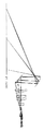
図1は、S9の画像投射装置の実施の1形態における要部を略示している。
Prior to the description of the embodiments of the invention below, the embodiments related to the reference techniques S1 to S34 will be described.
FIG. 1 schematically shows the main part of the first embodiment of the image projection apparatus of S9 .
符号15で示す「ライトバルブ」は、この実施の形態において液晶パネルであり、以下
、単にパネル15と称する。符号10で示す光源は、ランプとリフレクタによる発光部1
1と、この発光部11からの光束を照明光束とする照明光学系12とにより構成されてい
る。光源10からの照明光束は、パネル15に照射される。
A “light valve” indicated by
1 and an illumination
ライトバルブであるパネル15は「変調信号に応じて画像形成」され、形成された画像
は、光源10からの照明光束を2次元的に強度変調して透過させる。パネル15を透過し
た光束は、第1の光学系17と第2の光学系19により構成される「投射光学系」により
スクリーン21上に投射結像され、「パネル15に画像形成された画像」の拡大像を表示
する。
The
図2は、図1における投射光学系の部分を説明するための図である。 FIG. 2 is a diagram for explaining a portion of the projection optical system in FIG.
ライトバルブであるパネル15の投影側に、パネル15の側から第1、第2の順に配設
される第1及び第2の光学系17、19を有し、第1の光学系17は屈折光学系(レンズ
)で正のパワーを有し、第2の光学系19はパワーを有する反射面を有し、正のパワーを
有する。
On the projection side of the
パネル15により形成された画像は、第1及び第2の光学系17、19の光路上に中間
像Iintとして結像され、スクリーン21上には、この中間像Iintを「さらに拡大した画
像」が投射結像される。
The image formed by the
第1の光学系17は、図2において1枚のレンズとして示しているが、具体的には「屈
折光学系を含む種々の形態」、例えば、複数レンズによる構成や、レンズとミラーの組合
せ、反射面と屈折面を一体化した構成等が適宜可能である。
Although the first
第1の光学系17は、全体的に正のパワーを有しており、図2に示されたように、第1
の光学系17により形成される中間像Iintは「パネル15に形成された画像の倒立像」
である。中間像Iintの倍率は、パネル15上の画像の1〜数倍程度であることが好まし
い。中間像Iintが縮小像であると、第1および第2の光学系全体として「大きな拡大率
の表示画像」を得るためには、第2の光学系に大きな拡大倍率が必要となり、収差の補正
等と大倍率のバランスを実現することが困難になる。
The first
The intermediate image Iint formed by the
It is. The magnification of the intermediate image Iint is preferably about 1 to several times that of the image on the
逆に、中間像Iintの拡大倍率が大きくなりすぎると、第2の光学系のサイズが大きく
なり、投射光学系、延いては画像投射装置を大型化してしまう。
On the other hand, if the magnification of the intermediate image Iint is too large, the size of the second optical system is increased, and the projection optical system, and hence the image projection apparatus, is increased in size.
図2には、+側の最大像高(図1における位置:a)と−側の最大像高(図1における
位置:b)の2点に対応するパネル15上の位置:A、Bから上記位置:a、bへ向う光
束の光路を模式的に示している。
In FIG. 2, from positions A and B on the
中間像Iintは必ずしも「平面状に結像」する必要は無く、第1の光学系17と第2の
光学系19との合成光学系でスクリーン21上に投射される画像が「満足のいく画像」と
なるよう、合成光学系全体として性能を確保していればよい。従って、第1の光学系17
による結像性能には特に制約はない。
The intermediate image Iint does not necessarily have to be “planarly formed”, and the image projected on the
There are no particular restrictions on the imaging performance of the.
図1、図2に示す実施の形態においては、第1の光学系17により形成された中間像I
intを結像させた光束を、第2の光学系19で反射して光路を折り返し、中間像Iintを形
成する光束の進行方向と逆の向きに投射画像を投影するようになっている。
In the embodiment shown in FIGS. 1 and 2, the intermediate image I formed by the first
The light beam that forms an int is reflected by the second
図1、図2の実施の形態では、第2の光学系19を1面の凹面鏡で構成した例であるが
、第2の光学系の形態はこれに限らず、反射面を2以上含むことができるし、反射面とと
もに屈折光学系を含むこともできる。
In the embodiment of FIGS. 1 and 2, the second
図1、図2の構成において、第2の光学系中に「さらに1面の反射面を付け加える」こ
とにより、最終的に投射される光束の向きを「図1の向きと逆」にすることもできる。ま
た、図1、図2の構成において、中間像Iintの形成される位置と、反射面19との間に
、第2の光学系の一部として屈折光学系(レンズ系)を配し、反射面19に「より効率的に
光量を取り込む」ようにすることができる。
In the configuration of FIGS. 1 and 2, the direction of the finally projected light beam is made “reverse to the direction of FIG. 1” by “adding one more reflective surface” to the second optical system. You can also. 1 and FIG. 2, a refractive optical system (lens system) is arranged as a part of the second optical system between the position where the intermediate image Iint is formed and the reflecting
図2に示したように、パネル15における位置:Aを起点とする光束は、中間像Iint
における位置:A'に重心を持つように集まり、集光後の光線は、集束角と同じ発散角で
広がり、正のパワーを有する第2の光学系19により反射されて、図1におけるスクリー
ン21上の位置:aに結像する。
As shown in FIG. 2, the light beam starting from position A on
The light beam collected with a center of gravity at the position A ′ and condensed is spread at the same divergence angle as the converging angle, reflected by the second
同様に、パネル15における位置:Bを起点とする光束は、中間像Iintにおける位置:B'に重心を持つように集まり、集光後の光線は、集束角と同じ発散角で広がり、第2の光学系19により反射されて、図1におけるスクリーン21上の位置:bに結像する。
Similarly, the light beam starting from the position B on the
中間像Iintを形成させることにより、パネル15における位置:A、Bからの光束の結像に寄与する反射面19の有効領域を「局所的に狭める」ことが可能となる。即ち、図2に示すように、位置:Aからの光束に対する結像性能には、第2の光学系19の「反射領域A’’」の形状が影響し、位置:Bからの光束に対する結像性能は「反射領域B’’」の形状が影響する。
By forming the intermediate image Iint, it is possible to “locally narrow” the effective area of the reflecting
従って、図1、図2に示す構成により、反射領域A’’、B’’の面形状を最適化することが可能である。さらには、第2の光学系19における凹面の形状を「局所的に変化」させることにより、スクリーン21上の各部への集光特性が制御可能となる。
特に、上記凹面を自由曲面形状とすることでその効果を最大限に生かせる。
Therefore, it is possible to optimize the surface shapes of the reflection regions A ″ and B ″ by the configuration shown in FIGS. Furthermore, the condensing characteristic to each part on the
In particular, the effect can be maximized by making the concave surface a free-form surface.
従来から知られた光線追跡法などのシュミュレーション手法により、最適な諸元設定を
行えばよい。反射面により最適化を行えるので、色収差の発生、増加を抑えて、そのほか
の集光特性を向上させる設計が可能となる。
What is necessary is just to perform optimal specification setting by simulation methods, such as the ray tracing method known conventionally. Since the optimization can be performed by the reflecting surface, it is possible to design to improve the other light collecting characteristics while suppressing the occurrence and increase of chromatic aberration.
第1の光学系17は、屈折光学系を含むので、「反射面だけでは補正不能な色収差」を
屈折光学系により補正することが可能である。
Since the first
また、スクリーン21上に投射される投射像に影響する諸収差で、第2の光学系の反射
面のみでは補正できない部分は、第2の光学系に積極的に屈折光学系を取り入れて補正す
るようにしてもよい。
Further, various aberrations that affect the projected image projected on the
図1に示す如き構成において、第2の光学系19の結像倍率を高めるには、中間像Iin
tの形成される位置を、第2の光学系19の反射面に近づければよい。これを、図3、図
4を参照して説明する。
In the configuration as shown in FIG. 1, in order to increase the imaging magnification of the second
The position where t is formed may be close to the reflecting surface of the second
図3において、符号15はパネル、符号17Aは第1の光学系(レンズ)、符号19Aは
第2の光学系(凹面鏡)を示し、符号21はスクリーンを示す。
In FIG. 3,
光学系の緒元の表記に従い、パネル側から数えて、第i番目の面の曲率半径をRi(i
=1〜3 i=1は第1の光学系17Aの入射側面、i=3は第2の光学系19Aの反射
面)、第i番目の面と第i+1番目の面との間の面間隔をTi(i=0〜3 i=0はパ
ネル15と第1の光学系17Aの入射側面との間、i=3は第2の光学系19Aとスクリ
ーン21との間)とする。
According to the notation of the specification of the optical system, the radius of curvature of the i-th surface counted from the panel side is Ri (i
= 1 to 3 i = 1 is the incident side surface of the first
図3の光学系の緒元は以下の通りである。
i Ri(mm) Ti(mm) 材質
0 85
1 65 25 BK7
2 −55 225
3 −135 −400 。
The specifications of the optical system in FIG. 3 are as follows.
i Ri (mm) Ti (mm)
1 65 25 BK7
2-55 225
3-135-400.
パネル15における物体高は、±7.5mmである。
The object height in the
像高位置0(スクリーン21上のP点)で、投射画像が最適に結像するよう設定すると、
物体であるパネル15における位置:A、Bを起点として、スクリーン21上の位置:a
、bに到達する各主光線の間隔は約208mmとなる。
If the projection image is set to be optimally formed at the image height position 0 (P point on the screen 21),
Position on the
, B reaches about 208 mm.
ここで、図4に示すように、第1の光学系17Bと第2の光学系19Bを用い、第1の
光学系17Bのパワーを緩め、中間像Iintの位置を第1の光学系17Bから遠ざけるよ
うにし、同時に「像高0における集光性が保たれるように位置関係を保った」まま、第2
の光学系19Bにおける正のパワーを調整すると、これら光学系の緒元は以下の如くにな
る。
i Ri’(mm) Ti’(mm) 材質
0 85
1 65 25 BK7
2 −60 225
3 −98 −400 。
Here, as shown in FIG. 4, the first optical system 17B and the second
When the positive power in the
i Ri ′ (mm) Ti ′ (mm)
1 65 25 BK7
2-60 225
3-98-400.
パネル15における物体高は、±7.5mmである。
The object height in the
図4は、説明上、図3と光学配置を異なるように描いているが、上記緒元から明らかな
ように、光学系の配置は、図3の配置と同じであり、図3の光学系と異なっているのは第
1の光学系17Bの射出側面の曲率と、第2の光学系19Bの反射面の曲率のみである。
4 illustrates the optical arrangement different from that of FIG. 3 for the sake of explanation. As is apparent from the above description, the arrangement of the optical system is the same as that of FIG. The only difference is the curvature of the exit side surface of the first optical system 17B and the curvature of the reflection surface of the second
このとき、パネル15における位置:A、Bを起点として、スクリーン21上の位置:
a’、b’に到達する各主光線の間隔は約362mmとなり、図3に示す場合(208m
m)よりも拡大率が向上している。即ち、第1の光学系における正のパワーが弱まり、中
間像Iintが第2の光学系19Bの「正のパワーを持つ反射面」に近づいた結果、拡大率
が増大しているのである。上記のように、光学配置を変えることなく、屈折面・反射面の
曲率半径を変化させるのみで、拡大率を向上させることができる。
At this time, the position on the
The interval between the principal rays reaching a ′ and b ′ is about 362 mm, which is shown in FIG.
The enlargement ratio is improved over m). That is, the positive power in the first optical system is weakened and the intermediate image Iint approaches the “reflecting surface having positive power” of the second
上に説明したところを具体化するには、第1及び第2の光学系の光路上において「中間
像の結像位置を第2の光学系における正のパワーを持つ反射面に近づけるための、負のパ
ワーをもつ光学素子」を、中間像のライトバルブ側に設ければよい(S2)。
In order to embody the above description, on the optical path of the first and second optical systems, “to make the imaging position of the intermediate image close to the reflecting surface having positive power in the second optical system, An optical element having negative power ”may be provided on the light valve side of the intermediate image ( S2 ).
中間像の位置を第2の光学系における正のパワーを持つ反射面に近づけるために、中間
像のライトバルブ側に設ける負のパワーを持つ光学素子としては、凹レンズやフレネル凹
レンズ、凸面状の反射鏡、あるいはこれらの複合系等を考えることができる。
In order to bring the position of the intermediate image closer to the reflecting surface having a positive power in the second optical system, an optical element having a negative power provided on the light valve side of the intermediate image may be a concave lens, a Fresnel concave lens, a convex reflection A mirror or a composite system of these can be considered.
実際には、各像高位置での集光特性を確保し、像面の歪みを補正する必要があるが、屈
折面や反射面の面数を増やして設計の自由度を上げるなどし、従来から知られた光線追跡
法などによるシミュレーションで最適化設計を行えばよい。
Actually, it is necessary to secure the condensing characteristics at each image height position and correct the distortion of the image plane, but by increasing the number of refracting and reflecting surfaces to increase the degree of freedom of design, etc. Optimization design may be performed by simulation using a ray tracing method known from the above.
図5は、S3の実施の1形態を略示している。煩雑をさけるため、混同の虞がないと思われるものについては、図1におけると同一の符号を付した。
この実施の形態では、第2の光学系190は、正のパワーを有する反射面192と負のパワーを有する反射面191とを有する。
FIG. 5 schematically shows an embodiment of S3 . In order to avoid complications, the same reference numerals as those in FIG.
In this embodiment, the second
パネル15からの光束は第1の光学系17の作用により結像光束となるが、中間像Iin
tが結像される以前に、負のパワーを持つ反射面191に入射し、反射面192に向って
反射される。そして、中間像Iintは反射面191と反射面192との中間部に形成され
る。中間像Iintは、反射面192の正のパワーによりさらに拡大され、スクリーン21
上にパネル15上の画像が投射される。
The light beam from the
Before t is imaged, it enters the reflecting
The image on the
即ち、第2の光学系190における反射面191は、請求項2記載の発明における「中
間像Iintが形成される位置を、第2の光学系190の正のパワーを持つ反射面192に
近づける作用をもつ負のパワーを持つ光学系」の1例である。
That is, the reflecting
反射面191としては、凸反射面、フレネル凸反射鏡、正のパワーを持つホログラム反
射鏡等、発散パワーを有する反射光学素子を適宜に利用できる。
As the reflecting
中間像の位置をライトバルブから離すために、投射光学系は多少大きくならざるを得な
いが、上記「負のパワーをもつ光学系」を、反射鏡で構成することにより、光路を折り返
すレイアウトを採用でき、光学系全体のサイズは小さくすることができる。
In order to move the position of the intermediate image away from the light valve, the projection optical system must be somewhat larger, but by constructing the above "optical system with negative power" with a reflecting mirror, a layout that turns the optical path back. It can be adopted, and the size of the entire optical system can be reduced.
S2やS3の「中間像の結像位置を第2の光学系における正のパワーを持つ反射面に近づけるための、負のパワーをもつ光学素子」は、これを用いることにより、「第2の光学系における正のパワーを持つ反射面」への入射光束の「発散の程度」を狭める調整が可能となり、上記正のパワーを持つ反射面の「有効反射エリア」を小さくすることが可能となる。 In S2 and S3, “an optical element having a negative power for bringing the imaging position of the intermediate image close to a reflecting surface having a positive power in the second optical system” can be used to make “ It is possible to adjust to reduce the “degree of divergence” of the incident light beam on the “reflecting surface having positive power in the optical system”, and to reduce the “effective reflection area” of the reflecting surface having positive power. .
上記正のパワーを持つ反射面の有効反射エリアの調整や、同反射面の形状の局所的な形
状付与、即ち「自由曲面形状の設定」により、集光特性や歪みなどをよりきめ細かく制御
できる。
上記の如き構成の採用により、従来の投射光学系より広角化が可能となる。
By adjusting the effective reflection area of the reflecting surface having the positive power and providing the shape of the reflecting surface locally, that is, “setting of a free-form surface”, the light condensing characteristics and distortion can be controlled more finely.
By adopting the configuration as described above, a wider angle can be obtained than in the conventional projection optical system.
上の実施の形態で説明した各種の反射面のうち、少なくとも1面を自由曲面で構成する
ことにより、設計の自由度が増し、諸収差の補正がし易くなる(S4)。
By configuring at least one of the various reflecting surfaces described in the above embodiment as a free-form surface, the degree of freedom in design increases, and various aberrations can be easily corrected ( S4 ).
ここに謂う「自由曲面」は、アナモフィック面や、X−Yポリノミナル面等、「非回転
対称な面形状」を含む面である。
The so-called “free-form surface” is a surface including “non-rotationally symmetric surface shape” such as an anamorphic surface or an XY polynomial surface.
投射光学系に含まれる全ての面(屈折面、反射面)を自由曲面で構成すれば、設計上は、
極めて良好な結像特性を実現できるが、実際には各面の相対位置誤差や偏芯誤差等の要求
精度が厳しくなるので、自由曲面の数は多いほど良いというわけではなく、最適な自由曲
面の数を設定するのがよい。
If all surfaces (refractive surface, reflective surface) included in the projection optical system are configured with free-form surfaces,
Although extremely good imaging characteristics can be realized, the required accuracy such as relative position error and eccentricity error of each surface becomes strict, so the larger the number of free-form surfaces, the better. It is better to set the number of
上に説明したように、中間像Iintを形成した光束は、その後、発散光束となり、第2
の光学系における正のパワーを持つ反射面(凹面鏡)に入射する。従って、中間像Iintの
各位置からの発散性の光束は、上記凹面鏡における局所的な反射領域で反射されてスクリ
ーン上に結像する。換言すると、スクリーン上の各位置に結像する光束は、上記凹面鏡に
おいて「像高ごとに局所的な反射領域」に対応する。
As explained above, the light beam that formed the intermediate image Iint then becomes a divergent light beam,
Is incident on a reflecting surface (concave mirror) having positive power in the optical system. Accordingly, the divergent light beam from each position of the intermediate image Iint is reflected by the local reflection region of the concave mirror and forms an image on the screen. In other words, the light beam that forms an image at each position on the screen corresponds to a “local reflection region for each image height” in the concave mirror.
このことから、上記凹面鏡(中間像を形成した光束が、中間像形成後最初に反射される
反射面)の面形状を自由曲面とし「それぞれの像高に対する反射領域」ごとに、反射面の
曲面形状を調整することにより、最も効果的に諸収差補正が可能となり性能向上を図るこ
とができる(S5)。
For this reason, the surface of the concave mirror (the reflecting surface on which the light beam that formed the intermediate image is reflected first after the intermediate image is formed) is a free-form surface, and the curved surface of the reflecting surface for each “reflection region for each image height”. By adjusting the shape, various aberrations can be corrected most effectively and the performance can be improved ( S5 ).
面加工や組み付け性を考慮すると、自由曲面の数はできるだけ少ないのがよく、中間像
を形成した直後の正のパワーを有する反射面(凹面鏡)に優先的に適用するのが最も効果
的である。反射領域の調整に加え、「集光パワーを持つ凹面の局所的な形状を調整できる
自由曲面」の形状設定によって、集光特性や像の歪みなどの特性をより向上させる設計が
可能となる。
Considering surface processing and assembly, the number of free-form surfaces should be as small as possible, and it is most effective to preferentially apply to a reflecting surface (concave mirror) having a positive power immediately after forming an intermediate image. . In addition to the adjustment of the reflection region, the shape setting of “a free curved surface capable of adjusting the local shape of the concave surface having the light condensing power” enables the design to further improve the characteristics such as the light condensing characteristic and the image distortion.
中間像の倍率は「等倍〜数倍程度」であれば良く、中間像の形成に拘わる第1の光学系の結像倍率は大きい必要がない、従って、第1の光学系は、従来からある屈折光学系のみによる構成(S6)で最適化が可能である。第1の光学系を屈折光学系のみで構成すると、第1の光学系の光学設計が容易になり、面加工や組み付け性に関しても許容公差を緩くすることが可能となる。 The magnification of the intermediate image only needs to be “approximately 1 to several times”, and the imaging magnification of the first optical system related to the formation of the intermediate image does not need to be large. Therefore, the first optical system has been conventionally used. Optimization is possible with a configuration ( S6 ) using only a certain refractive optical system. If the first optical system is composed only of a refractive optical system, the optical design of the first optical system is facilitated, and the tolerances can be relaxed with respect to surface processing and assembly.
また、屈折面数等を増やして設計の自由度を増し、それにより、公差を分配して性能向
上させることも可能である。
It is also possible to increase the number of refracting surfaces and the like to increase the degree of design freedom, thereby distributing tolerances and improving performance.
S6では、第1の光学系を「屈折光学系のみ」で構成するが、さらなる性能向上を望む場合は「第1の光学系構成上の自由度をさらに向上させる」ことが必要となる。 In S6, the first optical system is configured by “only refractive optical system”. However, if further improvement in performance is desired, it is necessary to “further improve the degree of freedom in the configuration of the first optical system”.
このような更なる性能向上を図る場合には、第1の光学系を「回転対称軸を有する反射
面と屈折光学系とで構成」するのが良い(S7)。「回転対称軸を持つ反射面」は比較的作り易く、加工性と組み付け性を損なうことなく設計の自由度を向上するのに極めて有効である。この回転対称軸をもつ反射面を、非球面形状とすることによりさらに自由度が向上する。また、この反射面にシフト偏芯やチルト偏芯の自由度を与えることにより、より自由度を向上させた設計が可能となる。
In order to further improve the performance as described above, it is preferable that the first optical system is “configured by a reflecting surface having a rotational symmetry axis and a refractive optical system” ( S7 ). A “reflecting surface having a rotationally symmetric axis” is relatively easy to make and is extremely effective in improving the degree of freedom in design without impairing workability and assembly. The degree of freedom is further improved by making the reflecting surface having the rotational symmetry axis an aspherical surface. In addition, by providing the reflecting surface with a degree of freedom of shift eccentricity and tilt eccentricity , a design with improved degree of freedom becomes possible.
また、屈折光学系においても非球面形状を用いることができる。このような構成を採用
することにより設計の自由度が向上し、より高性能な投射光学系を実現できる。
An aspherical shape can also be used in the refractive optical system. By adopting such a configuration, the degree of freedom in design is improved, and a higher performance projection optical system can be realized.
反射面の加工には、従来から知られた研磨加工や、金型による成形加工、精密な形状転
写加工等、様々な加工法を採用できる。また、屈折透過面と反射面とが一体となった構成
とし、内部全反射構造としてもよい。
Various processing methods such as a conventionally known polishing process, a molding process using a mold, and a precise shape transfer process can be employed for processing the reflecting surface. Further, the refractive transmission surface and the reflection surface may be integrated to form an internal total reflection structure.
図1を参照して、画像投射装置の1形態を説明する。
光源10における発光部11のランプとしては、ハロゲンランプ、キセノンランプ、メ
タルハライドランプ、超高圧水銀ランプなどを用いることができる。
With reference to FIG. 1, one form of an image projection apparatus is demonstrated .
As the lamp of the light emitting unit 11 in the
高効率な照明効率を得られるように、ランプ近傍にランプと一体化して設けられたリフ
レクタを用いる。図1に図示されていないが、リフレクタにより反射されて「指向性を持
った光束」を、光強度を均一化してパネル15上に照射できるように「インテグレータ光
学系と呼ばれる公知の照度均一化手段」を用い、パネル面上に均一な照明分布の照明を行
うようにすることもできる。
In order to obtain high illumination efficiency, a reflector provided integrally with the lamp is used in the vicinity of the lamp. Although not shown in FIG. 1, “a well-known illuminance uniformizing unit called an integrator optical system” is used so that a “directed light beam” reflected by a reflector can be irradiated onto the
図1に、ライトバルブとして例示した透過型の液晶パネル15に換えて「反射型の液晶
ライトバルブ」を用いる場合は、偏光ビームスプリッタ等を用いて、照明光路と投射光路
を分離することにより「効率のよい照明」が可能である。
In the case of using a “reflective liquid crystal light valve” instead of the transmissive
また、ライトバルブとして「デジタル・マイクロミラー・デバイス(DMD)」を用い
る場合には「斜め入射光学系や全反射プリズムを使った光路分離光学系」を用いる。この
ようにライトバルブの種類に応じて適切な光学系を採用できる。
Further, when a “digital micromirror device (DMD)” is used as a light valve, an “optical path separation optical system using an oblique incident optical system or a total reflection prism” is used. Thus, an appropriate optical system can be employed according to the type of light valve.
フロントタイプのプロジェクタでは、投射画像を上方にシフトさせ、観察者からみて投
射画像がプロジェクタの陰にならないようにするのが良い。即ち、投射光学系の光軸(第
1の光学系17の光軸)に対して垂直な面内で、ライトバルブ15をシフト(図では下側
)し、投射光学系の下方から光束を入射させるようにしている。
In a front type projector, it is preferable to shift the projection image upward so that the projection image is not shaded by the projector. That is, the
ライトバルブ15の上記シフト量が大きいほど、第1の光学系17に要求される仕様と
して、特に有効画角を広くとる必要がある。ライトバルブ15の上記シフト量は必要に応
じて適宜の大きさに設定し、第1の光学系17により一旦中間像Iintを形成し、正のパ
ワーを有する第2の光学系19により、ライトバルブ15で形成した画像をスクリーン2
1上に拡大投射する。
As the shift amount of the
1 is enlarged and projected.
リアプロタイプでは、投射光路に平面ミラーを配置して、光路を折り曲げ空間占有率を
より小さくすることができることは当然である。
In the rear pro type, it is natural that a plane mirror can be arranged in the projection optical path, and the optical path can be bent to further reduce the space occupation ratio.
なお、上には簡単のため、パネル15を1枚のみ示したが、赤・緑・青用の3枚のパネ
ルを用い、各パネルにより変調された光束を、公知のダイクロイックプリズム等の色合成
手段により色合成した後に、第1の光学系17等へ入射させることにより、スクリーン2
1上にカラー画像を投射することができることは言うまでも無い。
For the sake of simplicity, only one
Needless to say, a color image can be projected onto the
以下に、S10〜24に関する実施の形態を説明する。 Below, the embodiment regarding S10-24 is described .
図6に示す実施の形態において、符号1で示す画像表示パネル(以下、単にパネル1と
いう)から符号2で示す「スクリーン」に向かう光束群の基準光線はスクリーン2の法線
と所定の傾きをもってスクリーン2に入射する。「基準光線」は、パネル1の中心からス
クリーン2に導光される光束の主光線とする。
In the embodiment shown in FIG. 6, the reference beam of the light beam group directed from the image display panel indicated by reference numeral 1 (hereinafter simply referred to as panel 1) to the “screen” indicated by
パネル1は反射型の液晶パネルで、直線偏光した照明光が、偏光ビームスプリッタ10Aを介して照射され、パネル1により変調された光束が偏光ビームスプリッタ10Aを介して結像光束となる。
The
光の伝搬においてパネル1側を「上流」、スクリーン2側を「下流」と呼ぶと、パネル
1の下流側に「屈折力をもつ透過面から成り、非球面を1面以上含」む透過光学系3が配
置され、その下流側に、複数の反射面4、5、6、7、8を有する「反射光学系」が配置
される。
In the light propagation, when the
パネル1からの結像光束は、透過光学系3内を伝搬し、反射光学系を構成する反射面4
〜8を介してスクリーン2へ導光される。反射光学系を構成する反射面4〜8のうち、反
射面8は「回転非対称反射面」となっている。
The imaging light beam from the
Is guided to the
透過光学系3には光束集光作用を与えることが好ましいが、この実施の形態では、透過
光学系3における「倍率拡大の作用負担」を緩め、特に「下流側のレンズの口径が大型化
しない」ようにしている。従って、拡大投射光学系としての倍率拡大の作用は、その全て
、もしくは相当部分を反射光学系が負っている。
Although it is preferable to give the light beam condensing function to the transmission
回転非対称反射面8によって「非対称収差(図において、上記基準軸の上下方向におけ
る非対称性に起因する収差)」を補正するとともに、透過光学系3の光軸をパネル1に対
して偏芯して設定(この実施の形態では、光軸が、パネル1の中心よりも、図の上方へ偏
芯している)することにより、非対称収差の補正効果を高くしている。即ち、透過光学系
3と反射光学系の双方に「非対称収差の補正を分担」させている。
The rotationally
透過光学系3はセル化を容易にするため「全体を共軸」に組付けている。
この実施の形態のように、拡大投射光学系を、透過光学系と反射光学系で構成すると、
全ての光学面を反射面で構成するよりも、光学系を組み付け易くなり、反射面による「光
路折り返し効果」も活かすことができ、全系を小型化できる。
The transmission
As in this embodiment, when the enlarged projection optical system is composed of a transmission optical system and a reflection optical system,
It is easier to assemble the optical system than when all the optical surfaces are made of reflecting surfaces, the “optical path folding effect” by the reflecting surfaces can be utilized, and the entire system can be downsized.
透過光学系3の下流側で反射面4の上流側には符号9で示す「絞り」が設けられ、絞り
9より下流側の反射面により、絞り9の像I9が「負の縮小倍率」で結像光路上に結像す
るようになっている。即ち、絞り9の「縮小倍率の像I9」は反射光学系の反射面4、5
、6、7の作用により、反射面7と回転非対称反射面8との間に倒立像として結像する。
A “diaphragm” indicated by reference numeral 9 is provided on the downstream side of the transmission
, 6 and 7, an inverted image is formed between the reflecting
このように、絞り9の像I9が縮小倍率で結像するようなパワー配置を取ると、絞り9
の像I9より下流側にある反射面(説明中の実施の形態では反射面8)に入射する光束が
大きく広がらないため、この反射面を小型にできる。
In this way, when the power is arranged such that the image I9 of the diaphragm 9 forms an image with a reduced magnification, the diaphragm 9
Since the light beam incident on the reflecting surface (the reflecting
上述の如く、絞り9の像I9は、反射光学系の光路内(反射面7と回転非対称反射面8
との間)で結像しており、この結像位置は「スクリーン側の瞳」、即ち拡大投射光学系の
「射出瞳」となる。
As described above, the image I9 of the stop 9 is in the optical path of the reflecting optical system (the reflecting
The image forming position is the “screen-side pupil”, that is, the “exit pupil” of the magnifying projection optical system.
結像光束は、反射光学系内の光路上においてパネル1の中間像を結像する。この中間像
は、絞り9の像I9と同様「負の倍率の実像」で等立像である。図に示す実施の形態では
、パネル1の中間像は反射面7の反射面近傍に結像される。即ち、パネル1の中間像は、
透過光学系3と反射面4〜6とにより形成される。
The imaging light beam forms an intermediate image of the
It is formed by the transmission
スクリーン2に結像するのは「パネル1の中間像の、反射面7と回転非対称反射面8に
よる拡大像」であり、このときの結像倍率も負である。このように、パネル1からの光束
は中間像が倒立像として結像され、さらにこの倒立像が倒立された正立像としてスクリー
ン2上に結像する。その際、中間像において発生する台形歪みが、スクリーン上に結像さ
れるときの台形歪みと相殺しあい、台形歪みの少ない表示画像を得ることができる。
The image formed on the
透過光学系3を1つのユニットとしてセル化すると、拡大投射光学系における位置調整
としては、セル化された透過光学系3と反射光学系との相対的な位置調整が残される。こ
のとき、反射光学系における最も上流側の反射面4のパワーが正であると、透過光学系3
から射出した光束が集光光束である場合、この光束は反射面4の正のパワーによりさらに
集光される作用を受ける。
When the transmission
When the light beam emitted from the light beam is a condensed light beam, the light beam is further condensed by the positive power of the reflecting surface 4.
この実施の形態では「反射面4のパワー」を負としている。反射面4のパワーを正にす
ると、透過光学系3と反射光学系の相対位置が「ズレ」たときに発生する収差が大きくな
る。換言すると、透過光学系3と「反射光学系」のズレ量が同一である場合、ズレ量に対
する収差の変化量が大きい。
In this embodiment, “power of the reflecting surface 4” is negative. When the power of the reflecting surface 4 is positive, the aberration that occurs when the relative position between the transmission
実施の形態のように、反射面4のパワーを負にすると上記「ずれ量に対する収差の変化
量」が小さい。従って、透過光学系3と反射光学系との相対的な位置関係の精度が緩やか
になり、光学系組付けが容易となる。
As in the embodiment, when the power of the reflecting surface 4 is negative, the “aberration change amount with respect to the shift amount” is small. Accordingly, the accuracy of the relative positional relationship between the transmission
上記反射面4のパワーを負にした上で、その下流に配置する反射面5のパワーは正とな
っている。反射光学系における上流側において、負のパワーの反射面が続くと入射光束の
発散性が過大になり、反射光学系内に「絞りの像」を結像させることができなくなる。
After making the power of the reflection surface 4 negative, the power of the reflection surface 5 arranged downstream is positive. If a negative power reflecting surface continues on the upstream side in the reflecting optical system, the divergence of the incident light beam becomes excessive, and an “aperture image” cannot be formed in the reflecting optical system.
反射面5のパワーを正とすることは、反射面5により反射される結像光束を収束傾向と
し、絞り9の像I9を反射光学系の光路内に結像する上で重要である。即ち、絞り9と絞
りの像I9の間に設ける光学系(反射面4〜7)の合成パワーは正である。
Making the power of the reflecting surface 5 positive is important for making the imaging light beam reflected by the reflecting surface 5 converge and tend to form the image I9 of the stop 9 in the optical path of the reflecting optical system. That is, the combined power of the optical system (reflecting surfaces 4 to 7) provided between the stop 9 and the stop image I9 is positive.
反射面4とともに反射面5も負のパワーとし、その下流側の反射面6のパワーを正にし
ても良いが、反射面6のパワーを強くする必要性が生じたり、面間距離が長くなったりし
て収差発生量が増え、光学系が大きくなり、構成面数も増えるので、メリットはあまりな
い。
The reflecting surface 5 as well as the reflecting surface 4 may have negative power and the power of the reflecting surface 6 on the downstream side may be positive. However, it is necessary to increase the power of the reflecting surface 6 or the distance between the surfaces becomes long. As a result, the amount of aberration increases, the optical system becomes larger, and the number of components increases, so there is not much merit.
パネル1とスクリーン2が共に平面で「斜め投射」を行う拡大投射光学系において、こ
の発明では「パネル1側からスクリーン2へ向う光束が生成するパネル1の、負の倍率の
中間像」と、「スクリーン2側からパネル1へ向う光束が生成するスクリーン2の、負の
倍率の中間像」の位置・形状が略一致するように、中間像面の上流側および下流側の光学
系を構成している。
In the magnifying projection optical system in which both the
「スクリーン2側からパネル1に向う光束」は、拡大投射光学系設計の際に、スクリー
ンを物体面、パネルを像面として光線追跡を行う際において使用される仮想的な光束を言
う。
The “light beam from the
反射光学系部において、回転非対称反射面8は、この実施の形態におけるように、結像
光束の光路上、最下流のスクリーン2に最も近い位置に配置することが好ましい。反射面
4〜8における「異なる画角に対応する各々の光束」の入射位置は、上流においては重な
っている領域が広く、下流に行くほど「重なる領域」が少なくなるようにする。
In the reflection optical system portion, the rotationally
回転非対称反射面は、入射位置に対して取り得る面形状の自由度が高いので、回転非対
称反射面8を最下流側とし、この面位置において「異なる画角に対応する各々の光束の互
いに重なる領域」が少なくなるようにすると、回転非対称反射面8よりも上流側の光学系
による「各画角の光束が有する残存収差の補正に適する面形状」を回転非対称反射面8に
与えることができ、高い収差補正効果を実現できる。
Since the rotationally asymmetric reflecting surface has a high degree of freedom of the surface shape that can be taken with respect to the incident position, the rotationally
上記とは逆に、反射光学系の上流側に回転非対称反射面を設けると、その反射面の同位
置に「異なる画角の光束が重なって入射している状態」となるから、異なる画角の光束の
各々が有する収差を同時に補正する「反射面の形状解」を得ることが困難になる。
Contrary to the above, if a rotationally asymmetric reflecting surface is provided on the upstream side of the reflecting optical system, the light beams with different angles of view are incident on the same position of the reflecting surface. It is difficult to obtain a “reflecting surface shape solution” that simultaneously corrects aberrations of each of the light beams.
この実施の形態においては、透過光学系3にも「非対称収差成分の補正」を分担させる
ことができる。このような場合、補正効果を高くするには、透過光学系3に「回転非対称
な透過面」を与える。回転非対称面は「回転対称非球面では補正困難な収差成分を補正」
するのに有効である。
In this embodiment, the transmission
It is effective to do.
反射光学系は複数の反射面4〜8で構成されているが、これらをユニットとして一体に
構成することによって、反射面同士の相対位置精度を出し易くなり、拡大投射光学系の組
付けが容易になる。反射面の一体化は例えばモールド成形法によって実現できるが、これ
に限らず、他の適宜の方法で実現して良い。
The reflective optical system is composed of a plurality of reflective surfaces 4 to 8. However, when these are integrated as a unit, the relative positional accuracy between the reflective surfaces can be easily obtained, and the enlarged projection optical system can be easily assembled. become. The integration of the reflecting surfaces can be realized by, for example, a molding method, but is not limited thereto, and may be realized by other appropriate methods.
若干付言すると、絞り9を配置する位置は、図1の位置に限らず、例えば、透過光学系3における面間に設けても良い。この場合には、絞りの像の結像に、透過光学系の一部も参与することになる。
In other words, the position where the diaphragm 9 is disposed is not limited to the position shown in FIG. 1, and may be provided between the surfaces of the transmission
画像表示パネルは1枚に限らず、3枚の画像表示パネルを用い、R(赤)、G(緑)、
B(青)の各色成分画像を色ごとに異なる画像表示パネルに表示し、これら画像表示パネ
ルからの光を合成して、拡大投射光学系によりスクリーンへ導光し、スクリーン上にカラ
ー画像を表示するように構成することもできる。
The image display panel is not limited to one, and three image display panels are used, and R (red), G (green),
Each color component image of B (blue) is displayed on a different image display panel for each color, and the light from these image display panels is combined and guided to the screen by an enlarged projection optical system, and a color image is displayed on the screen. It can also be configured to.
このような場合には、図1において、パネル1と透過光学系3との間の偏光ビームスプ
リッタとダイクロイクプリズムを組合せたもの(カラー画像投射装置において広く知られ
ている)を用いることができる。
また、スクリーンは必ずしも平面でなくてもよい。
In such a case, in FIG. 1, a combination of a polarizing beam splitter between the
Further, the screen does not necessarily have to be a plane.
上に説明したように、図1に示す拡大投射光学系は、画像表示パネル1からの光束をスクリーン2に導光し、スクリーン2の法線に対し傾斜した方向から投射して、スクリーン2上に画像表示パネル1に表示された画像の拡大像を結像させる拡大投射光学系であって、反射光学系4〜8と透過光学系3とを有し、反射光学系はパワーをもつ複数の反射面4〜8により構成され、回転非対称反射面8を含み、透過光学系3は屈折力をもつ透過面により構成され、非球面を1面以上含む(S10)。
As described above, the enlarged projection optical system shown in FIG. 1 guides the light beam from the
透過光学系3における画像表示パネル側から第1面と、反射光学系におけるスクリーン
側から第1面との間に絞り9が設けられ、そのスクリーン側に配置した光学素子4〜7に
より、絞り9の像I9が負の縮小倍率で結像するように構成されている(S11)。
A diaphragm 9 is provided between the first surface from the image display panel side in the transmission
図1の拡大投射装置はまた、複数の透過面からなる透過光学系3と、複数の反射面4〜
8から成る反射光学系と、絞り9とを有し、反射光学系における反射面のうち、絞り9を
通過した光束が最初に入射するパワーを持つ反射面4のパワーが負であり(S12)、絞り9を通過した光束が最初に入射する負のパワーを持つ反射面4に続く反射面5が正のパワーを持ち(S13)、反射光学系は、パワーを持つ複数の反射面4〜8により構成され、回転非対称反射面8を含み、透過光学系3は屈折力をもつ透過面により構成され、非球面を1面以上含む(S14)。
1 also includes a transmission
The reflection optical system comprising 8 and the stop 9 have a negative power of the reflection surface 4 having the power at which the light beam that has passed through the stop 9 first enters among the reflection surfaces in the reflection optical system ( S12 ). The reflecting surface 5 following the reflecting surface 4 having negative power on which the light beam having passed through the diaphragm 9 first enters has positive power ( S13 ), and the reflecting optical system has a plurality of reflecting surfaces 4 to 8 having power. And includes the rotationally
図1の拡大投射光学系はまた、画像表示パネル1側からスクリーン2に至る光束が生成
する画像表示パネルの負の倍率の中間像と、スクリーン2側から画像表示パネル1に至る
光束が生成するスクリーン2の負の倍率の中間像の位置・形状が略一致し(S15)、複数の反射面から成る反射光学系4〜8と、複数の透過面からなる透過光学系3とを有し(S16)、絞り9を有し、反射光学系における反射面のうち、絞りを通過した光束が最初に入射するパワーを持つ反射面4のパワーが負であり(S17)、絞り9を通過した光束が最初に入射する負のパワーを持つ反射面4に続く反射面5が正のパワーを持ち(S18)、反射光学系はパワーを持つ複数の反射面により構成され、回転非対称反射面8を含み、透過光学系3は屈折力をもつ透過面により構成され、非球面を1面以上含む(S19)。
The magnification projection optical system of FIG. 1 also generates a negative magnification intermediate image of the image display panel that generates a light beam from the
さらに、回転非対称反射面8は、投射光路上において「最もスクリーン2側」に配置さ
れ(S20)、透過光学系3が、屈折力を有する回転非対称な透過面を含み(S21)、画像表示パネル1の位置に対し、透過光学系3の光軸が、導光光路を含む面内で偏芯して設定されている(S22)。また、反射光学系はユニットとして一体に構成することができる(S23)。
Further, the rotationally
従って、図6に示した拡大投射光学系に対して、公知の各種の光源を付加することにより、画像表示パネル1に画像を表示し、画像表示パネル1を光源からの光で照明し、照明された画像表示パネル1からの光束を拡大投射光学系によりスクリーン2に導光し、スクリーン2の法線に対し傾斜した方向から投射して、スクリーン2上に画像表示パネル1に表示された画像の拡大像を投射する拡大投射装置であって、拡大投射光学系としてS9〜23の任意の1の拡大投射光学系を用いた拡大投射装置(S24)を実現できる。
Therefore, by adding various known light sources to the enlarged projection optical system shown in FIG. 6, an image is displayed on the
以下、S25〜34の実施の形態を説明する。 Hereinafter, embodiments of S25 to 34 will be described.
図7は、S25の投射光学系を有する画像投射装置の実施の1形態を示している。投射光学系の部分を拡大して図8に示す。 FIG. 7 shows an embodiment of an image projection apparatus having the projection optical system of S25 . A portion of the projection optical system is enlarged and shown in FIG.
図8において、符号71で示す部分は物体側に配された第1の光学系、符号72で示す
部分は像側に配された第2の光学系を示す。第1の光学系71はレンズ711〜716で
構成されレンズ713の直後に絞りSを有する。レンズ713は「接合レンズ」である。
符号721、722は第2の光学系を構成する2面の反射面を示している。
In FIG. 8, a portion denoted by
第1の光学系71の物体側は、図6に即して説明したような「反射型の液晶パネルに、
直線偏光した照明光を、偏光ビームスプリッタを介して照射し、液晶パネルにより変調さ
れた反射光束が偏光ビームスプリッタを介して結像光束となる型のもの」が想定され、符
号PBが「偏光ビームスプリッタ」を示している。
The object side of the first
It is assumed that the linearly polarized illumination light is irradiated through a polarizing beam splitter and the reflected light beam modulated by the liquid crystal panel becomes an imaging light beam through the polarizing beam splitter. A splitter is shown.
物体側からの光束は第1の光学系71、第2の光学系72を介して図示されない投影面
(図7に示すスクリーン)上に画像を投射するが、物体の中間像は反射面721と722
の間の位置に結像し、反射面722により投影面上に正規像として結像する。
The light beam from the object side projects an image on a projection surface (screen shown in FIG. 7) (not shown) via the first
An image is formed at a position between and a normal image is formed on the projection surface by the
「投射されるべき画像を表示する物体」としてはまた、図1に即して示した「ライトバ
ルブ15を、ランプとリフレクタによる発光部11からの光束を照明光学系12により照
明する構成のもの」を用いることができる。発光部の具体例としては、ハロゲンランプ、
キセノンランプ、メタルハライドランプ、超高圧水銀ランプなどが好適である。照明光学
系には「リフレクタにより反射されて指向性を持った光束の強度をライトバルブに対して
均一化するインテグレータ光学系」を搭載することもできる。
As the “object for displaying the image to be projected”, the “
A xenon lamp, a metal halide lamp, an ultrahigh pressure mercury lamp, or the like is suitable. The illumination optical system can also be equipped with an “integrator optical system that makes the intensity of the light beam reflected by the reflector and having directivity uniform with respect to the light valve”.
上記物体としてはまた、DMDパネルに対し「斜め入射光学系」や全反射プリズムで、
光路分離を行う方式のものを用いることもできる。勿論、LEDアレイやELアレイ、プ
ラズマディスプレイ等の自己発光型の物体を用いることもできる。
As the above object, “obliquely incident optical system” or total reflection prism with respect to the DMD panel,
A system that performs optical path separation can also be used. Of course, self-luminous objects such as LED arrays, EL arrays, and plasma displays can also be used.
即ち、図7、図8に示す実施の形態における投射光学系は、屈折光学系(レンズ711
等)を少なくとも1つ含み、正のパワーを有する第1の光学系71と、パワーを有する反
射面(721等)を少なくとも1つ含み、全体で正のパワーを有する第2の光学系72と
を有し、物体面に近い側から第1、第2の光学系の順に配置され、物体像が一旦中間像と
して形成された後に正規像として結像されるように構成され、第1の光学系において物体
側にもっとも近い屈折力を持った光学要素711の光軸に対して他の光学要素712〜7
16、721、722が平行偏芯および/またはチルト偏芯している(S25)。
That is, the projection optical system in the embodiment shown in FIGS. 7 and 8 is a refractive optical system (lens 711).
And the like, and a first
16, 721, and 722 are parallel eccentricity and / or tilt eccentricity ( S25 ).
S26〜34に関する構成は参考具体例として後述する。 The configuration related to S26 to 34 will be described later as a reference specific example .
図12に、請求項1記載の投射光学系を有する画像投射装置の実施の1形態を示す。
図13にその投射光学系の部分を拡大して示す。
図13において、符号100で示す部分は、図6に即して説明した「反射型の液晶パネ
ルに、直線偏光した照明光を、偏光ビームスプリッタを介して照射し、液晶パネル1によ
り変調された反射光束が偏光ビームスプリッタを介して結像光束となる型」の物体側部分
であり、反射型の液晶パネルの画像表示面が「被投影物体面」である。図中、符号PBが
偏光ビームスプリッタを示す。物体側の構成はこれに限らず、図1に即して説明した「ラ
イトバルブ15を、ランプとリフレクタによる発光部11からの光束を照明光学系12に
より照明する構成のもの、あるいはこれにインテグレ−タ光学系を付加したもの」を用い
ることもできるし、DMDパネルに対し斜め入射光学系や全反射プリズムで光路分離を行
う方式のものを用いることもでき、LEDアレイやELアレイ、プラズマディスプレイ等
の自己発光型の物体を用いることもできる。
FIG. 12 shows an embodiment of an image projection apparatus having the projection optical system according to
FIG. 13 shows an enlarged portion of the projection optical system.
In FIG. 13, the part denoted by
符号120で示す部分は「透過型屈折光学系」を示し、符号130で示す部分は「反射
型屈折光学系」である。
A portion denoted by
透過型屈折光学系120はレンズ121〜127により構成されている。レンズ123
とレンズ126とは接合レンズであり、全体は9枚のレンズで構成されている。反射型屈
折光学系130は第1の反射ミラー131(反射面のみを示す。)、第2の反射ミラー1
32(反射面のみを示す。)からなる。
The transmissive refractive
The
32 (only the reflecting surface is shown).
即ち、図12、図13に示す投射光学系では、被投影物体面からの光束は、透過型屈折
光学系120と、この透過型屈折光学系の側から第1及び第2の順に配置される2枚の反
射ミラー131、132から成る反射型屈折光学系130を介して図示されない投影面上
に導光されて投影される。
That is, in the projection optical system shown in FIGS. 12 and 13, the light beam from the object surface to be projected is arranged in the first and second order from the transmission type refractive
透過型屈折光学系120は複数の透過型屈折素子121〜127を有し、図示の如く、
投影物体面から透過型屈折光学系の第1面(レンズ121の物体側面)までは、図に示さ
れたように「略テレセントリック」であり、反射型屈折光学系130における2枚の反射
ミラー131、132の間に、被投影物体面の中間像面が位置し、中間像面における中間
像が、第2の反射ミラー132を介して投影面上に正規像として再結像される。
The transmissive refractive
From the projection object surface to the first surface of the transmissive refractive optical system (the object side surface of the lens 121) is “substantially telecentric” as shown in the figure, and the two reflecting
後述する実施例1に示すように、第1の反射ミラー131は負のパワーの軸対称な反射面であり、第2の反射ミラー132は「上下方向と左右方向とでパワーが異なるアナモフィックな多項式自由曲面」であり(請求項3)、第2の反射ミラー132から図示されない投影面に至る光線は投影面の法線に対して傾斜して導光される。
As shown in Example 1 described later, the first reflecting
そして、透過型屈折光学系120は、被投影物体面の法線に対して偏芯するが、透過型
屈折光学系の有する複数の透過型屈折素子121〜127は互いに偏芯することなく構成
されている。
The transmission refractive
レンズ123とレンズ126とは接合レンズであり、これら接合レンズ123、126
はそれぞれレンズの「群単位」を構成するが、これら接合レンズは「群単位レベルでは互
いに偏芯することなく構成」されている(請求項2)。
The
Each constitutes a “group unit” of the lens, and these cemented lenses are “configured without decentering each other at the group unit level” ( claim 2 ).
また、反射ミラー132、133の間に結像される中間像の像面は図13から分かるように「被投影物体面の中心から射出する光束の主光線に対して傾斜湾曲して」おり(請求項6)、透過型屈折光学系の最終面(レンズ127の射出側面)において「被投影物体面の中心から射出した主光線と、被投影物体面の周辺から射出した主光線とが略平行」である。
Further, as shown in FIG. 13, the image plane of the intermediate image formed between the reflecting
図12の画像投射装置は「フロントプロジェクタ型」であるが(請求項8)、勿論、結像光路内に光路を折り曲げる反射鏡を付加することにより「リアプロジェクタ型」とすることができる(請求項9)。 Although the image projection apparatus of FIG. 12 is a "front projector type" (claim 8), of course, it can be a "rear projector type" by adding a reflecting mirror for bending the optical path in the imaging optical path (according Item 9 ).
以下、参考技術に関する参考具体例と、請求項1以下の発明に関する実施例を挙げる。
光学系の諸元において、面番号は物体面(投射されるべき画像が表示される面)を第0
面として、以下順次に第1面、第2面・・と数える。全実施例を通じ、第1面および第2
面は「偏光ビームスプリッタ」の液晶パネル側および投射光学系側の面である。
「参考具体例1」 Hereinafter, exemplified in Reference Examples relating to the reference technique, the examples relating to claim 1 following invention.
In the specifications of the optical system, the surface number is the 0th object surface (the surface on which the image to be projected is displayed).
The surfaces are sequentially counted as a first surface, a second surface, and so on. Through all examples, the first side and the second side
The surfaces are surfaces of the “polarization beam splitter” on the liquid crystal panel side and the projection optical system side.
“Reference Example 1”
参考具体例1は、先に、図7、図8に示した画像投射装置・投射光学系の具体的な実施例である。即ち、屈折光学系を少なくとも1つ含み、正のパワーを有する第1の光学系71と、パワーを有する反射面を少なくとも1つ含み、全体で正のパワーを有する第2の光学系72とを有し、物体面に近い側から第1、第2の光学系の順に配置され、物体像が一旦中間像として形成された後に正規像として結像されるように構成され、第1の光学系において物体側にもっとも近い屈折力を持った光学要素711の光軸に対して他の光学要素712〜716、721、722が平行偏芯および/またはチルト偏芯している。
中間像の拡大率は3倍程度である。
Reference specific example 1 is a specific example of the image projection apparatus / projection optical system shown in FIGS. That is, a first
The magnification of the intermediate image is about 3 times.
参考具体例1の諸元を表1に示す。 Table 1 shows the specifications of Reference Specific Example 1 .

表1において、シフトとあるのはシフト偏芯量、チルトとあるのはチルト偏芯量を示す
。曲率半径、面間隔およびシフト偏芯量の単位は「mm」、チルト偏芯量の単位は「度」
である。以下の各実施例においても同様である。
In Table 1, “shift” indicates the amount of shift eccentricity, and “tilt” indicates the amount of tilt eccentricity. The unit of curvature radius, surface spacing and shift eccentricity is “mm”, and the unit of tilt eccentricity is “degree”.
It is. The same applies to the following embodiments.
第18面である第2の反射ミラーの反射面は前述の式(1)で示される「上下方向と左
右方向とでパワーが異なるアナモフィックな多項式自由曲面」であるが、この多項式自由
曲面における係数を表2に挙げる。
The reflecting surface of the second reflecting mirror, which is the 18th surface, is an “anamorphic polynomial free-form surface having different powers in the vertical direction and the left-right direction” represented by the above-described equation (1). Are listed in Table 2.
上記の表記において例えば「1.14641E-11」は「1.14641×10⁻¹¹」を意味する。以下に
おいても同様である。
In the above notation, for example, “1.14641E-11” means “1.14641 × 10 −11 ”. The same applies to the following.
上記の如く、第1の光学系は7枚のレンズにより構成され、第2の光学系は2面の反射
面で構成されているが、反射面721は球面で、反射面722は多項式自由曲面である。
As described above, the first optical system is composed of seven lenses, and the second optical system is composed of two reflecting surfaces, but the reflecting
正規像の像面(スクリーン)は、図7の左右方向に平行な平面であるが、像高の低い位
置(物体に近い側)と高い位置(物体から遠い側)ではスクリーンへ入射する角度の差が
大きため「下すぼみの歪んだ投射画像」になりがちであるが、中間像の歪みを逆に設定し
、最終像面での歪みを補正した。
The image plane (screen) of the normal image is a plane parallel to the left-right direction in FIG. 7, but the angle of incidence on the screen is low at a position where the image height is low (side closer to the object) and at a position where the image height is high (side far from the object). Although the difference is large, it tends to be a “projection image with a distorted bottom dent”, but the distortion of the intermediate image is set in reverse to correct the distortion on the final image plane.
最終的な像面での「像の歪みの状態」を図11に示す。図11は、対角:略0.9イン
チの液晶パネルの表示される画像をスクリーン上に60インチ程度に拡大して投射した時
のディストーションの様子を示している。図の如く、グリッドの像を略等間隔に形成でき
、台形歪みが良好に補正されていることが分かる。投射サイズは1200mm×900m
mサイズ、拡大率は65倍以上で、歪みは0.5%以下で非常に良好である。
「参考具体例2」
FIG. 11 shows an “image distortion state” on the final image plane. FIG. 11 shows a state of distortion when an image displayed on a liquid crystal panel having a diagonal of about 0.9 inches is projected on the screen by being enlarged to about 60 inches. As shown in the figure, it can be seen that the grid images can be formed at substantially equal intervals, and the trapezoidal distortion is well corrected. Projection size is 1200mm x 900m
The size m and the enlargement ratio are 65 times or more, and the distortion is 0.5% or less, which is very good.
“Reference Example 2”
参考具体例2は、図9に示す画像投射装置・投射光学系の具体的な実施例である。図9は、画像投射装置の投射光学系部分を拡大して示している。 Reference specific example 2 is a specific example of the image projection apparatus / projection optical system shown in FIG. FIG. 9 is an enlarged view of the projection optical system portion of the image projection apparatus.
第1の光学系81は6枚のレンズ811〜816により構成され、第2の光学系82は
2枚の反射面821、822により構成されている。図示されない絞りが、レンズ813
とレンズ814の間に配置されている。
The first
And the
参考具体例1と同様、中間像は反射面821、822の中間に、第1の光学系81により反転像として形成される。また、第2の光学系82に入射した光側を最初に反射する正のパワーを有する反射面821は回転対称な非球面形状とし、反射面822は多項式自由曲面とした。回転対称な非球面形状の採用により、自由度のより高い設計が可能となった例である。
As in Reference Example 1 , the intermediate image is formed as a reverse image by the first
参考具体例2の諸元を表3に示す。 Table 3 shows specifications of Reference Specific Example 2 .
第16面に用いられている回転対象の非球面は、Zを光軸方向のデプス、cを近軸曲率
半径、rを光軸からの光軸直交方向の距離、kを円錐定数、A、B、C、・・等を高次の
非球面係数とする周知の非球面式:
Z=c・r2/[1+√{1-(1+k)c2r2}]+Ar4+Br6+Cr8
において、k、A、B、Cを与えて形状を特定する。以下の他の実施例においても同様で
ある。
The aspherical surface to be rotated used in the sixteenth surface is such that Z is the depth in the optical axis direction, c is the paraxial radius of curvature, r is the distance in the optical axis orthogonal direction from the optical axis, k is the conic constant, A, A well-known aspherical expression in which B, C,...
Z = c · r 2 / [1 + √ {1- (1 + k) c 2 r 2 }] + Ar 4 + Br 6 + Cr 8
The shape is specified by giving k, A, B, and C. The same applies to the following other embodiments.
第16面の非球面の係数を表4に与える。 Table 16 gives the coefficients of the aspheric surface of the sixteenth surface.
第17面の多項式自由曲面の係数の値を表5に与える。 Table 5 gives the values of the coefficients of the polynomial free-form surface of the 17th surface.
「参考具体例3」
"Reference Example 3"
参考具体例3は、図10に示す画像投射装置・投射光学系の具体的な実施例である。
第1の光学系91は5枚のレンズ911〜915により構成され、第2の光学系92は
2枚の反射面921、922により構成されている。レンズ913は接合レンズである。
図示されない絞りが、レンズ913とレンズ914の間に配置されている。
Reference specific example 3 is a specific example of the image projection apparatus / projection optical system shown in FIG.
The first
A diaphragm (not shown) is disposed between the
参考具体例1、2と同様、中間像は反射面921、922の中間に形成される。第1の光学系により中間像が反転像として形成される。また、第2の光学系に入射した光側を最初に反射する正のパワーを有する反射面921は球面形状、反射面922は多項式自由曲面である。
Similar to the reference specific examples 1 and 2, the intermediate image is formed between the reflecting
参考具体例3の諸元を表6に示す。 Table 6 shows the specifications of Reference Specific Example 3.
表6から明らかなように、レンズ911の第1面(表6において第3面)は2.2度チ
ルトしているが、このレンズ911の光軸に対し、レンズ912〜915はチルト偏芯せ
ず、レンズ911〜915はレンズ911の光軸に対して平行偏芯しているのみである。
屈折光学系は1組の接合レンズ913を含み、これは1群として作用する。
As is clear from Table 6, the first surface of lens 911 (the third surface in Table 6) is tilted by 2.2 degrees, but
The refractive optical system includes a set of cemented
第16面の多項式自由曲面の係数の値を表7に示す。 Table 17 shows the coefficient values of the polynomial free-form surface of the sixteenth surface.
参考具体例4は、上にあげた参考具体例3と同様の光学系構成(図10)で諸元を異ならせたものである。 The reference specific example 4 is different from the above-mentioned reference specific example 3 in the optical system configuration (FIG. 10).
参考具体例4の諸元を表8に示す。 Table 8 shows the specifications of Reference Concrete Example 4.
第16面の多項式自由曲面の係数の値を表9に示す。 Table 9 shows the coefficient values of the polynomial free-form surface of the sixteenth surface.
参考具体例5も、上にあげた参考具体例3と同様の光学系構成(図10)で諸元を異ならせたものである。 The reference specific example 5 also has different specifications with the same optical system configuration (FIG. 10) as the reference specific example 3 given above.
参考具体例5の諸元を表10に示す。 Table 10 shows the specifications of Reference Specific Example 5.
第16面の多項式自由曲面の係数の値を表11に示す。 Table 11 shows the coefficient values of the polynomial free-form surface of the sixteenth surface.
上述したように、上記参考具体例1〜5は、屈折光学系を少なくとも1つ含み、正のパワーを有する第1の光学系と、パワーを有する反射面を少なくとも1つ含み、全体で正のパワーを有する第2の光学系とを有し、物体面に近い側から第1、第2の光学系の順に配置され、物体像が一旦中間像として形成された後に正規像として結像されるように構成され、第1の光学系において物体側にもっとも近い屈折力を持った光学要素の光軸に対して、他の光学要素が、1カ所以上において、平行偏芯および/またはチルト偏芯しており(S25)、参考具体例3〜5では、第1の光学系91において物体側にもっとも近い、屈折力
を持った光学要素911の光軸に対して第1の光学系91の各要素がチルト偏芯していな
い(S26)。
As described above, each of the reference specific examples 1 to 5 includes at least one refractive optical system, includes a first optical system having a positive power, and at least one reflecting surface having a power. A second optical system having power, arranged in the order of the first and second optical systems from the side closer to the object plane, and once the object image is formed as an intermediate image, it is formed as a normal image With respect to the optical axis of the optical element having the refractive power closest to the object side in the first optical system, the other optical element has parallel eccentricity and / or tilt eccentricity at one or more locations. ( S25 ), in Reference Specific Examples 3 to 5, each of the first
また、参考具体例3〜4では、第1の光学系91が2以上の群で構成され、2以上の群のうちの接合レンズとして1つの群をなすレンズ913が平行偏芯している(S27)。
In Reference Specific Examples 3 to 4, the first
参考具体例1〜5とも、第2の光学系に含まれる反射面の1以上が、自由曲面であり(S28)、第2の光学系に含まれる反射面のうち、正規像の結像位置側に最も近い反射面
のみが自由曲面であり(S29)、参考具体例1〜5では、第2の光学系に入射した光束
が初めて反射される正のパワーを有する反射面が回転対称な面であり(S30)、参考具体例1、3、〜5においては上記回転対称な反射面が球面反射面である(S31)。
In Reference Specific Examples 1 to 5 , one or more of the reflecting surfaces included in the second optical system are free-form surfaces ( S28 ), and the imaging position of the regular image among the reflecting surfaces included in the second optical system. Only the reflection surface closest to the side is a free-form surface (S29), and in Reference Examples 1 to 5, the reflection surface having a positive power for reflecting the light beam incident on the second optical system for the first time is a rotationally symmetric surface. ( S30 ), and in Reference Examples 1 , 3, and 5, the rotationally symmetric reflective surface is a spherical reflective surface ( S31 ).
また、参考具体例1〜5とも第1の光学系が屈折光学系のみで構成され(S32)、第
1の光学系における屈折光学系には、非球面形状が含まれていない(S33)。
In each of Reference Specific Examples 1 to 5, the first optical system is configured only by a refractive optical system ( S32 ), and the refractive optical system in the first optical system does not include an aspherical shape ( S33 ).
従って、上記参考具体例の投射光学系に物体を組み合わせた画像投射装置は、S34の画像投射装置の具体例を構成する。 Therefore, the image projection apparatus combining an object with the projection optical system of the above reference specific example constitutes a specific example of the image projection apparatus of S34 .
以下に挙げる実施例1は、先に、図12、図13に即して実施の形態を説明した投射光
学系・画像投射装置の具体的実施例である。
Example 1 given below is a specific example of the projection optical system / image projection apparatus whose embodiment has been described with reference to FIGS.
実施例1の諸元を表12に示す。 Table 12 shows the specifications of Example 1 .
第7面と第15面の非球面の係数を表13に与える。 Table 13 gives the aspheric coefficients of the seventh and fifteenth surfaces.
第19面と第21面の多項式自由曲面の係数の値を表14に与える。 Table 14 gives the values of the coefficients of the polynomial free-form surfaces of the 19th and 21st surfaces.
実施例1の投射光学系によるスクリーン上におけるMTF性能は周波数:0.5c/m
mにおいて60%以上、ディストーションは2%以下である。
実施例6において正規像を投射するスクリーンのサイズは60インチであり、投射光学
系の「スクリーンに直交する方向の最大幅」は472mmである。
The MTF performance on the screen by the projection optical system of Example 1 has a frequency of 0.5 c / m.
The m is 60% or more, and the distortion is 2% or less.
In Example 6, the size of the screen for projecting the normal image is 60 inches, and the “maximum width in the direction perpendicular to the screen” of the projection optical system is 472 mm.
図14に示す如く、スクリーンに、X方向(左右方向)とY方向(上下方向)とにおい
て、±1.0Y、±0.5Y、0.0Y、±1.0X、±0.5X、0.0Xの碁盤状の線を設
定し、評価周波数:0.5c/mmに対するMTF値を調べたところ、表15の如くにな
った。
As shown in FIG. 14, the screen has ± 1.0Y, ± 0.5Y, 0.0Y, ± 1.0X, ± 0.5X, 0 in the X direction (left and right direction) and Y direction (up and down direction). When a 0.0X grid-like line was set and the MTF value for the evaluation frequency: 0.5 c / mm was examined, it was as shown in Table 15.
図15に、X=0.0Xにおける周波数:0〜0.5c/mmの範囲における±1.0Y
、0.0Yにおけるサジタル方向(s)およびメリディオナル方向(m)のMTF特性を
示す。図16に、X=0.5Xにおける周波数:0〜0.5c/mmの範囲における±1.
0Y、0.0Yにおけるサジタル方向(s)およびメリディオナル方向(m)のMTF特
性を示す。図17に、X=1.0Xにおける周波数:0〜0.5c/mmの範囲における
±1.0Y、0.0Yにおけるサジタル方向(s)およびメリディオナル方向(m)のMT
F特性を示す。これらの図から明らかなように、実施例1は良好なMTF特性を有してい
る。
FIG. 15 shows the frequency at X = 0.0X: ± 1.0 Y in the range of 0 to 0.5 c / mm.
MTF characteristics in the sagittal direction (s) and the meridional direction (m) at 0.0Y. FIG. 16 shows a frequency at X = 0.5X: ± 1.0 in a range of 0 to 0.5 c / mm.
The MTF characteristics in the sagittal direction (s) and the meridional direction (m) at 0Y and 0.0Y are shown. FIG. 17 shows the frequency at X = 1.0X: ± 1.0Y in the range of 0 to 0.5c / mm, MT in sagittal direction (s) and meridional direction (m) at 0.0Y.
F characteristics are shown. As is clear from these figures, Example 1 has good MTF characteristics.
実施例1の投射光学系は、反射屈型屈折光学系は透過型屈折光学系の側から第1、第2
の順に配置される2枚の反射ミラーを有し、被投影物体面の中間像面が上記第1及び第2
の反射ミラーの間に位置し、第1の反射ミラーは負のパワーの軸対称な反射面(第22面
)、第2の反射ミラーは上下方向と左右方向とでパワーが異なるアナモフィックな多項式自由曲面(第23面)であり(請求項3)、被投影物体面の中間像の、アスペクト比を補正する手段として、透過型屈折光学系内に、上下方向と左右方向とでパワーが異なるア
ナモフィックな多項式自由曲面(第19面)を有する(請求項4)。
In the projection optical system of Example 1, the catadioptric refractive optical system is first and second from the transmission refractive optical system side.
Are arranged in this order, and the intermediate image plane of the object surface to be projected is the first and second
The first reflecting mirror is an axisymmetric reflecting surface with negative power (22nd surface), and the second reflecting mirror is an anamorphic polynomial whose power is different in the vertical and horizontal directions. curved a (23rd surface) (claim 3), anamorphic as a means for correcting the intermediate image of the projection object surface, the aspect ratio, the transmission refractive optical endothelial system, the powers in the vertical and horizontal directions different polynomial has a free-form surface (surface No. 19) (claim 4).
また、透過型屈折光学系における被投影物体面側のNA(=0.143)が、中間像面側のNA(=0.01)よりも大きく(請求項5)、中間像の倍率:M1(=1.5)は1〜5の範囲にあり、投影倍率(=75倍)は40以上であり、投影面に対する投射角度:θ(=11度)は5°より大きい。 Further, the NA (= 0.143) on the projection object plane side in the transmissive refractive optical system is larger than the NA (= 0.01) on the intermediate image plane side, and the magnification of the intermediate image: M1 (= 1.5) is in the range of 1 to 5, the projection magnification (= 75 times) is 40 or more, the projection angle with respect to the projection plane: theta (= 11 deg) is greater than 5 °.
L1 第1レンズ
L2 第2レンズ
L3 第3レンズ
1 画像表示パネル
2 スクリーン
3 透過光学系
4〜8 反射光学系を構成する反射面
8 回転非対称反射面
9 絞り
I9 絞りの像
L1 1st lens L2 2nd lens L3
Claims (9)
透過型屈折光学系は複数の透過型屈折素子を有し、
被投影物体面から上記透過型屈折光学系の第1面までが略テレセントリックであり、
上記透過型屈折光学系よりも上記反射型屈折光学系側の結像光路上の空間に、上記被投影物体面の中間像面が位置し、上記中間像面における倒立した中間像が、1枚のみの上記反射ミラーを介して投影面上に正規像として再結像され、
上記反射型屈折光学系の上記1枚のみの反射ミラーは、上下方向と左右方向とでパワーが異なるアナモフィックな多項式自由曲面であり、
上記透過型屈折光学系と上記1枚のみの反射ミラーとの間に上記中間像を結像させ、該中間像を結像した後の発散する光束を上記1枚のみの反射ミラーで反射し、その反射光の光束が上記1枚のみの反射ミラーのパワーで上記投影面に集束し、さらに、上記反射型屈折光学系から上記投影面に至る光線が、上記投影面の法線に対して傾斜して導光され、
上記透過型屈折光学系は被投影物体面の法線に対して偏芯し、上記透過型屈折光学系の有する複数の透過型屈折素子は互いに偏芯することなく構成されていることを特徴とする投射光学系。 A projection optical system that guides and projects a light beam from a projection object surface onto a projection surface via a transmission type refractive optical system and a reflective type refractive optical system including a single reflection mirror;
The transmission refractive optical system has a plurality of transmission refractive elements,
The surface from the object surface to be projected to the first surface of the transmission refractive optical system is substantially telecentric,
The intermediate image plane of the object surface to be projected is located in a space on the imaging optical path closer to the reflective refractive optical system than the transmissive refractive optical system, and one inverted intermediate image on the intermediate image plane Is re-imaged as a normal image on the projection plane through the above-mentioned reflection mirror,
The single reflection mirror of the reflective refractive optical system is an anamorphic polynomial free-form surface having different power in the vertical direction and the horizontal direction,
The intermediate image is formed between the transmissive refractive optical system and the single reflection mirror, and the divergent light beam after the intermediate image is formed is reflected by the single reflection mirror. The reflected light beam is focused on the projection surface by the power of the single reflection mirror, and the light beam from the reflective refractive optical system to the projection surface is tilted with respect to the normal line of the projection surface. Is guided,
The transmission-type refractive optical system is decentered with respect to the normal line of the projection object surface, and the plurality of transmission-type refractive elements included in the transmission-type refractive optical system are configured without being decentered from each other. Projection optical system.
透過型屈折光学系は複数の透過型屈折素子を有し、
被投影物体面から上記透過型屈折光学系の第1面までが略テレセントリックであり、
上記透過型屈折光学系よりも上記反射型屈折光学系側の結像光路上の空間に、上記被投影物体面の中間像面が位置し、上記中間像面における倒立した中間像が、1枚のみの上記反射ミラーを介して投影面上に正規像として再結像され、
上記反射型屈折光学系の上記1枚のみの反射ミラーは、上下方向と左右方向とでパワーが異なるアナモフィックな多項式自由曲面であり、
上記透過型屈折光学系と上記1枚のみの反射ミラーとの間に上記中間像を結像させ、該中間像を結像した後の発散する光束を上記1枚のみの反射ミラーで反射し、その反射光の光束が上記1枚のみの反射ミラーのパワーで上記投影面に集束し、さらに、上記反射型屈折光学系から上記投影面に至る光線が、上記投影面の法線に対して傾斜して導光され、
上記透過型屈折光学系は被投影物体面の法線に対して偏芯し、上記透過型屈折光学系の有する複数の透過型屈折素子は群単位レベルでは互いに偏芯することなく構成されていることを特徴とする投射光学系。 A projection optical system that guides and projects a light beam from a projection object surface onto a projection surface via a transmission type refractive optical system and a reflective type refractive optical system including a single reflection mirror;
The transmission refractive optical system has a plurality of transmission refractive elements,
The surface from the object surface to be projected to the first surface of the transmission refractive optical system is substantially telecentric,
The intermediate image plane of the object surface to be projected is located in a space on the imaging optical path closer to the reflective refractive optical system than the transmissive refractive optical system, and one inverted intermediate image on the intermediate image plane Is re-imaged as a normal image on the projection plane through the above-mentioned reflection mirror,
The single reflection mirror of the reflective refractive optical system is an anamorphic polynomial free-form surface having different power in the vertical direction and the horizontal direction,
The intermediate image is formed between the transmissive refractive optical system and the single reflection mirror, and the divergent light beam after the intermediate image is formed is reflected by the single reflection mirror. The reflected light beam is focused on the projection surface by the power of the single reflection mirror, and the light beam from the reflective refractive optical system to the projection surface is tilted with respect to the normal line of the projection surface. Is guided,
The transmissive refractive optical system is decentered with respect to the normal line of the projection object surface, and the transmissive refractive elements of the transmissive refractive optical system are configured so as not to be decentered from each other at the group unit level. A projection optical system characterized by that.
反射型屈折光学系は透過型屈折光学系の側から第1、第2の順に配置される2枚の反射ミラーを有し、
被投影物体面の中間像面が上記第1及び第2の反射ミラーの間に位置し、
上記第1の反射ミラーは負のパワーの軸対称な反射面、上記第2の反射ミラーは上下方向と左右方向とでパワーが異なるアナモフィックな多項式自由曲面であることを特徴とする投射光学系。 The projection optical system according to claim 1 or 2,
The reflective refractive optical system has two reflective mirrors arranged in the first and second order from the transmission refractive optical system side,
An intermediate image plane of the projection object surface is located between the first and second reflecting mirrors;
The projection optical system, wherein the first reflecting mirror is an axisymmetric reflecting surface having a negative power, and the second reflecting mirror is an anamorphic polynomial free-form surface having different powers in the vertical direction and the horizontal direction.
被投影物体面の中間像の、アスペクト比を補正する手段として、
透過型屈折光学系内に、上下方向と左右方向とでパワーが異なるアナモフィックな多項
式自由曲面を有することを特徴とする投射光学系。 In the projection optical system according to claim 1, 2 or 3,
As a means to correct the aspect ratio of the intermediate image of the projected object surface,
A projection optical system comprising an anamorphic polynomial free-form surface having different powers in a vertical direction and a horizontal direction in a transmissive refractive optical system.
透過型屈折光学系における被投影物体面側のNAが、中間像面側のNAよりも大きいことを特徴とする投射光学系。 In the projection optical system according to any one of claims 1 to 4,
A projection optical system characterized in that the NA on the object side to be projected in the transmissive refractive optical system is larger than the NA on the intermediate image plane side.
中間像面が、被投影物体面の中心から射出する光束の主光線に対して傾斜湾曲していることを特徴とする投射光学系。 In the projection optical system according to any one of claims 1 to 5,
A projection optical system, characterized in that the intermediate image plane is inclined and curved with respect to a principal ray of a light beam emitted from the center of the projection object surface.
投射光学系として、請求項1〜6の任意の1に記載のものを用いたことを特徴とする画像投射装置。 An image projection apparatus that projects an image displayed on a projection object surface on a projection surface by a projection optical system,
An image projection apparatus using the optical system according to any one of claims 1 to 6 as a projection optical system.
フロントプロジェクタ型であることを特徴とする画像投射装置。 The image projection apparatus according to claim 7, wherein
An image projection apparatus characterized by being a front projector type.
結像光路を折り返す折り返しミラーを有し、リアプロジェクタ型であることを特徴とする画像投射装置。 The image projection apparatus according to claim 7, wherein
An image projection apparatus having a folding mirror for folding an imaging optical path and being a rear projector type.
Priority Applications (12)
| Application Number | Priority Date | Filing Date | Title |
|---|---|---|---|
| JP2003409304A JP4223936B2 (en) | 2003-02-06 | 2003-12-08 | Projection optical system, enlargement projection optical system, enlargement projection apparatus, and image projection apparatus |
| US10/771,523 US7048388B2 (en) | 2003-02-06 | 2004-02-05 | Projection optical system, magnification projection optical system, magnification projection apparatus, and image projection apparatus |
| US11/345,493 US7441908B2 (en) | 2003-02-06 | 2006-02-02 | Projection optical system, magnification projection optical system, magnification projection apparatus, and image projection apparatus |
| US12/055,520 US20080304019A1 (en) | 2003-02-06 | 2008-03-26 | Projection optical system, magnification projection optical system, magnification projection apparatus, and image projection apparatus |
| US12/233,672 US7637618B2 (en) | 2003-02-06 | 2008-09-19 | Projection optical system, magnification projection optical system, magnification projection apparatus, and image projection apparatus |
| US12/233,653 US7631975B2 (en) | 2003-02-06 | 2008-09-19 | Projection optical system, magnification projection optical system, magnification projection apparatus, and image projection apparatus |
| US12/233,650 US7637621B2 (en) | 2003-02-06 | 2008-09-19 | Projection optical system, magnification projection optical system, magnification projection apparatus, and image projection apparatus |
| US12/582,363 US7922341B2 (en) | 2003-02-06 | 2009-10-20 | Projection optical system, magnification projection optical system, magnification projection apparatus, and image projection apparatus |
| US12/909,540 US7938545B2 (en) | 2003-02-06 | 2010-10-21 | Projection optical system, magnification projection optical system, magnification projection apparatus, and image projection apparatus |
| US13/861,124 USRE45258E1 (en) | 2003-02-06 | 2013-04-11 | Projection optical system, magnification projection optical system, magnification projection apparatus, and image projection apparatus |
| US13/973,783 USRE45728E1 (en) | 2003-02-06 | 2013-08-22 | Projection optical system, magnification projection optical system, magnification projection apparatus, and image projection apparatus |
| US15/462,378 USRE48309E1 (en) | 2003-02-06 | 2017-03-17 | Projection optical system, magnification projection optical system, magnification projection apparatus, and image projection apparatus |
Applications Claiming Priority (3)
| Application Number | Priority Date | Filing Date | Title |
|---|---|---|---|
| JP2003029595 | 2003-02-06 | ||
| JP2003029602 | 2003-02-06 | ||
| JP2003409304A JP4223936B2 (en) | 2003-02-06 | 2003-12-08 | Projection optical system, enlargement projection optical system, enlargement projection apparatus, and image projection apparatus |
Related Child Applications (1)
| Application Number | Title | Priority Date | Filing Date |
|---|---|---|---|
| JP2007220413A Division JP4210314B2 (en) | 2003-02-06 | 2007-08-27 | Projection optical system, enlargement projection optical system, enlargement projection apparatus, and image projection apparatus |
Publications (3)
| Publication Number | Publication Date |
|---|---|
| JP2004258620A JP2004258620A (en) | 2004-09-16 |
| JP2004258620A5 JP2004258620A5 (en) | 2007-10-11 |
| JP4223936B2 true JP4223936B2 (en) | 2009-02-12 |
Family
ID=32830635
Family Applications (1)
| Application Number | Title | Priority Date | Filing Date |
|---|---|---|---|
| JP2003409304A Expired - Lifetime JP4223936B2 (en) | 2003-02-06 | 2003-12-08 | Projection optical system, enlargement projection optical system, enlargement projection apparatus, and image projection apparatus |
Country Status (2)
| Country | Link |
|---|---|
| US (11) | US7048388B2 (en) |
| JP (1) | JP4223936B2 (en) |
Cited By (2)
| Publication number | Priority date | Publication date | Assignee | Title |
|---|---|---|---|---|
| EP2410378A1 (en) | 2010-07-21 | 2012-01-25 | Ricoh Company, Ltd. | Projection optical system and image projection device |
| US9606425B2 (en) | 2015-06-19 | 2017-03-28 | Canon Kabushiki Kaisha | Imaging optical system, optical apparatus and image projection apparatus |
Families Citing this family (189)
| Publication number | Priority date | Publication date | Assignee | Title |
|---|---|---|---|---|
| US7714943B2 (en) * | 2002-06-12 | 2010-05-11 | Geo Semiconductor Inc. | Ultra-thin image projection system |
| US7150537B2 (en) | 2002-08-16 | 2006-12-19 | Infocus Corporation | Projection television device and screen |
| JP4223936B2 (en) * | 2003-02-06 | 2009-02-12 | 株式会社リコー | Projection optical system, enlargement projection optical system, enlargement projection apparatus, and image projection apparatus |
| JP2005181965A (en) * | 2003-11-25 | 2005-07-07 | Ricoh Co Ltd | Spatial light modulator, display device, and projection display device |
| JP2005234452A (en) * | 2004-02-23 | 2005-09-02 | Konica Minolta Opto Inc | Projection optical system |
| FR2878968B1 (en) * | 2004-12-03 | 2008-02-22 | Thomson Licensing Sa | PROJECTION SYSTEM |
| BRPI0509037A (en) * | 2004-03-30 | 2007-08-07 | Thomson Licensing | projection module and projector built into it |
| JP2005301074A (en) * | 2004-04-14 | 2005-10-27 | Konica Minolta Opto Inc | Projection optical system |
| US7495831B2 (en) * | 2004-08-20 | 2009-02-24 | Ricoh Company, Ltd. | Optical device, display device, and three-dimension image display device for changing a polarization state of a light beam in time |
| KR100677134B1 (en) * | 2004-09-24 | 2007-02-02 | 삼성전자주식회사 | Slim projection optical system and image display device |
| CN100417969C (en) * | 2004-10-21 | 2008-09-10 | 索尼株式会社 | Projection optical system and projection type image display device |
| TWI289210B (en) * | 2004-10-21 | 2007-11-01 | Sony Corp | Projection optical system and projection type image display device |
| JP5102940B2 (en) * | 2004-11-01 | 2012-12-19 | 株式会社日立製作所 | Projection image display device and projection optical unit used therefor |
| JP2006178406A (en) * | 2004-11-25 | 2006-07-06 | Konica Minolta Opto Inc | Projection optical system |
| JP4890771B2 (en) | 2005-02-28 | 2012-03-07 | 富士フイルム株式会社 | Projection optical system and projection display device using the same |
| JP5114828B2 (en) * | 2005-04-08 | 2013-01-09 | 株式会社日立製作所 | Projection optical unit |
| JP2006292900A (en) * | 2005-04-08 | 2006-10-26 | Hitachi Ltd | Projection optical unit and projection type image display apparatus using the same |
| JP4718883B2 (en) * | 2005-04-11 | 2011-07-06 | Necディスプレイソリューションズ株式会社 | Projection display |
| JP2006308830A (en) * | 2005-04-28 | 2006-11-09 | Konica Minolta Opto Inc | Projecting optical system |
| US20070014027A1 (en) * | 2005-07-12 | 2007-01-18 | Ken Agatsuma | Projection device |
| US20070058229A1 (en) * | 2005-09-15 | 2007-03-15 | Russell Hudyma | Volumetric Three-Dimensional Display System |
| JP4933083B2 (en) * | 2005-11-04 | 2012-05-16 | 株式会社日立製作所 | Projection-type image display device and projection optical unit thereof |
| KR100772383B1 (en) * | 2005-11-22 | 2007-11-01 | 삼성전자주식회사 | Compact rear projection display |
| JP4910384B2 (en) * | 2005-12-16 | 2012-04-04 | 株式会社日立製作所 | Free-form optical element and projection optical unit or projection-type image display apparatus including the same |
| DE102006003524A1 (en) * | 2006-01-24 | 2007-07-26 | Oerlikon Contraves Ag | Panoramic view system especially in combat vehicles |
| US7530694B2 (en) * | 2006-02-01 | 2009-05-12 | Mitsubishi Digital Electronics America, Inc. | Flat projection television |
| JP4965133B2 (en) * | 2006-02-09 | 2012-07-04 | 株式会社リコー | Optical system and image display device |
| JP4267023B2 (en) * | 2006-04-25 | 2009-05-27 | 三菱電機株式会社 | Projection display |
| JP5006069B2 (en) | 2006-05-01 | 2012-08-22 | 株式会社リコー | Projection optical system and image display apparatus |
| US20080186415A1 (en) * | 2006-06-16 | 2008-08-07 | Alphacurve, Inc. | Curved screen display system and method |
| JP5374848B2 (en) | 2006-09-15 | 2013-12-25 | 株式会社リコー | Projection optical system |
| JP5937962B2 (en) * | 2006-09-15 | 2016-06-22 | 株式会社リコー | Projection optical system and image projection apparatus |
| JP5585709B2 (en) * | 2006-09-15 | 2014-09-10 | 株式会社リコー | Image projection device |
| JP2008096983A (en) | 2006-09-15 | 2008-04-24 | Ricoh Co Ltd | Projection optical system and image projection device |
| CN101154025B (en) * | 2006-09-29 | 2010-09-15 | 三洋电机株式会社 | Projection-type image display device and projection-type image display system |
| JP4467609B2 (en) * | 2006-09-29 | 2010-05-26 | 三洋電機株式会社 | Projection display apparatus and projection display system |
| JP4464948B2 (en) * | 2006-10-13 | 2010-05-19 | 株式会社日立製作所 | Projection display system |
| JP4668159B2 (en) | 2006-11-06 | 2011-04-13 | ソニー株式会社 | Projection optical system and projection-type image display device |
| JP5030732B2 (en) * | 2006-12-04 | 2012-09-19 | 株式会社リコー | Projection optical system and image projection apparatus |
| JP5181637B2 (en) * | 2006-12-04 | 2013-04-10 | 株式会社リコー | Image projection device |
| CN100449350C (en) * | 2006-12-07 | 2009-01-07 | 浙江大学 | Super thin reflective projection display imaging method and objective lens based on free camber |
| US20080151199A1 (en) * | 2006-12-21 | 2008-06-26 | Bao-Gang Wu | Projection display system of quasi-axial optical imagery |
| EP1950594A1 (en) | 2007-01-17 | 2008-07-30 | Carl Zeiss SMT AG | Imaging optical system, projection illumination unit for microlithography with such an optical system, method for manufacturing a microstructured component with such a projection illumination unit, microstructured component produced by the manufacturing method and use of such an optical system |
| WO2008090001A1 (en) | 2007-01-25 | 2008-07-31 | Young Optics Inc. | Rear projection apparatus and method for a rear projection apparatus |
| JP5060792B2 (en) | 2007-01-29 | 2012-10-31 | 三洋電機株式会社 | Projection optical system, projection unit, and projection display device |
| JP2008191211A (en) * | 2007-02-01 | 2008-08-21 | Tohoku Univ | Projector |
| JP4329863B2 (en) * | 2007-02-14 | 2009-09-09 | コニカミノルタオプト株式会社 | Projection optical system and image projection apparatus |
| US7922340B2 (en) | 2007-02-14 | 2011-04-12 | Konica Minolta Opto, Inc. | Projection optical system with enlargement at a varying magnification |
| WO2008108203A1 (en) | 2007-03-01 | 2008-09-12 | Konica Minolta Opto, Inc. | Projection optical system |
| US8113667B2 (en) | 2007-03-01 | 2012-02-14 | Konica Minolta Opto, Inc. | Projection optical system |
| JP2008216643A (en) | 2007-03-05 | 2008-09-18 | Sanyo Electric Co Ltd | Projection type display device |
| US8246176B2 (en) | 2007-03-06 | 2012-08-21 | Sanyo Electric Co., Ltd. | Projection display device having an operation section for displacing a lens |
| US7967453B2 (en) | 2007-03-06 | 2011-06-28 | Sanyo Electric Co., Ltd. | Holding structure for holding a member in an external cabinet |
| US7901092B2 (en) | 2007-03-06 | 2011-03-08 | Sanyo Elctric Co., Ltd | Projection display device having a level difference correction section |
| JP4901595B2 (en) * | 2007-03-06 | 2012-03-21 | 三洋電機株式会社 | Projection display |
| US8096663B2 (en) | 2007-03-06 | 2012-01-17 | Sanyo Electric Co., Ltd. | Projection display device and stand used for the projection display device |
| JP2008216867A (en) | 2007-03-07 | 2008-09-18 | Sanyo Electric Co Ltd | Projection type display device |
| JP4909141B2 (en) | 2007-03-16 | 2012-04-04 | 三洋電機株式会社 | Projection display |
| US7857463B2 (en) * | 2007-03-29 | 2010-12-28 | Texas Instruments Incorporated | Optical system for a thin, low-chin, projection television |
| JP5002319B2 (en) | 2007-04-27 | 2012-08-15 | 三洋電機株式会社 | Projection display |
| US7967448B2 (en) * | 2007-07-02 | 2011-06-28 | Texas Instruments Incorporated | Optical system for a thin, low-chin, projection television |
| US8128238B2 (en) | 2007-09-07 | 2012-03-06 | Ricoh Company, Ltd. | Projection optical system and image displaying apparatus |
| JP5286963B2 (en) * | 2007-09-07 | 2013-09-11 | 株式会社リコー | Projection optical system |
| JP4829196B2 (en) | 2007-09-28 | 2011-12-07 | 株式会社リコー | Projection optical device |
| US8014075B2 (en) | 2007-11-06 | 2011-09-06 | Seiko Epson Corporation | Projection type image display device |
| CN101884001A (en) * | 2007-11-30 | 2010-11-10 | 3M创新有限公司 | Comprise toric optical element and preparation method thereof |
| JP5166847B2 (en) * | 2007-12-14 | 2013-03-21 | 三洋電機株式会社 | Projection display device |
| JP5045429B2 (en) * | 2007-12-27 | 2012-10-10 | コニカミノルタアドバンストレイヤー株式会社 | Oblique projection optical system |
| JP5422897B2 (en) * | 2008-02-27 | 2014-02-19 | 株式会社リコー | Projection optical system and image display apparatus |
| JP5476668B2 (en) * | 2008-03-13 | 2014-04-23 | 株式会社リコー | Projection optical system |
| WO2009119808A1 (en) * | 2008-03-27 | 2009-10-01 | 三洋電機株式会社 | Projection video display device |
| US20090257117A1 (en) * | 2008-04-09 | 2009-10-15 | Tomoyuki Baba | Projection optical system and projection type display using the same |
| JP5153485B2 (en) * | 2008-07-01 | 2013-02-27 | 三菱電機株式会社 | Rear projection display |
| JP5181899B2 (en) * | 2008-07-25 | 2013-04-10 | 株式会社リコー | Image reading apparatus and image forming apparatus |
| JP5359607B2 (en) * | 2008-09-02 | 2013-12-04 | 株式会社リコー | Variable magnification optical system, projector |
| JP2010164944A (en) * | 2008-12-16 | 2010-07-29 | Olympus Corp | Projection optical system and visual display apparatus using the same |
| JP5332686B2 (en) | 2009-02-13 | 2013-11-06 | セイコーエプソン株式会社 | Projection optical system and projection-type image display device |
| JP5412875B2 (en) * | 2009-02-26 | 2014-02-12 | 株式会社リコー | Front projector |
| JP5412884B2 (en) * | 2009-03-04 | 2014-02-12 | 株式会社リコー | Optical system and image display device |
| US8054556B2 (en) * | 2009-03-13 | 2011-11-08 | Young Optics Inc. | Lens |
| TWI413822B (en) * | 2009-03-13 | 2013-11-01 | Young Optics Inc | Lens |
| JP5484098B2 (en) * | 2009-03-18 | 2014-05-07 | 三菱電機株式会社 | Projection optical system and image display apparatus |
| JP5358280B2 (en) * | 2009-05-12 | 2013-12-04 | 日立コンシューマエレクトロニクス株式会社 | Projection board device and transmissive screen used therefor |
| US8279527B2 (en) * | 2009-06-16 | 2012-10-02 | Delta Electronics, Inc. | Wide-angle projection optical system |
| JP2011033738A (en) * | 2009-07-30 | 2011-02-17 | Fujifilm Corp | Projection optical system and projection type display using the same |
| JP2011033737A (en) | 2009-07-30 | 2011-02-17 | Fujifilm Corp | Projection optical system and projection type display using the same |
| US20110068258A1 (en) * | 2009-09-18 | 2011-03-24 | Tekolste Robert D | Nonrotationally symmetric lens, imaging system including the same, and associated methods |
| JP4965631B2 (en) * | 2009-11-25 | 2012-07-04 | 株式会社リコー | Optical system and image display device |
| EP2369401B1 (en) * | 2010-03-23 | 2015-09-23 | Max-Planck-Gesellschaft zur Förderung der Wissenschaften e.V. | Optical modulator device and spatio-temporally light modulated imaging system |
| KR101091236B1 (en) * | 2010-04-02 | 2011-12-07 | 엘지이노텍 주식회사 | Projector opitcal system |
| JP5703591B2 (en) * | 2010-05-18 | 2015-04-22 | 株式会社リコー | Projection optical system and image projection apparatus |
| JP5561087B2 (en) * | 2010-10-14 | 2014-07-30 | 株式会社リコー | Image projection device |
| KR101070583B1 (en) * | 2010-12-10 | 2011-10-06 | 주식회사 슈프리마 | Optical structure for acquiring image of fingerprint |
| JP5621583B2 (en) | 2010-12-27 | 2014-11-12 | 株式会社リコー | Projection optical system and image projection apparatus |
| JP5907404B2 (en) * | 2011-03-15 | 2016-04-26 | 株式会社リコー | Image projection device |
| JP5835647B2 (en) | 2011-07-01 | 2015-12-24 | 株式会社ニコン | Catadioptric lens |
| CN103782222B (en) * | 2011-07-05 | 2016-01-27 | 日东光学株式会社 | Projection optics system and projection arrangement |
| JP5790248B2 (en) | 2011-07-27 | 2015-10-07 | 株式会社リコー | Image projection device |
| CN102287763B (en) * | 2011-08-09 | 2012-10-03 | 深圳亚锐光电科技有限公司 | Oriented emergent light lens |
| US8390917B1 (en) | 2011-08-24 | 2013-03-05 | Palo Alto Research Center Incorporated | Multiple line single-pass imaging using spatial light modulator and anamorphic projection optics |
| US9030515B2 (en) | 2011-08-24 | 2015-05-12 | Palo Alto Research Center Incorporated | Single-pass imaging method using spatial light modulator and anamorphic projection optics |
| US8767270B2 (en) | 2011-08-24 | 2014-07-01 | Palo Alto Research Center Incorporated | Single-pass imaging apparatus with image data scrolling for improved resolution contrast and exposure extent |
| US8477403B2 (en) | 2011-08-24 | 2013-07-02 | Palo Alto Research Center Incorporated | Variable length imaging apparatus using electronically registered and stitched single-pass imaging systems |
| US9630424B2 (en) | 2011-08-24 | 2017-04-25 | Palo Alto Research Center Incorporated | VCSEL-based variable image optical line generator |
| US8670172B2 (en) | 2011-08-24 | 2014-03-11 | Palo Alto Research Center Incorporated | Variable length imaging method using electronically registered and stitched single-pass imaging |
| US8872875B2 (en) | 2011-08-24 | 2014-10-28 | Palo Alto Research Center Incorporated | Single-pass imaging system with anamorphic optical system |
| US8472104B2 (en) | 2011-08-24 | 2013-06-25 | Palo Alto Research Center Incorporated | Single-pass imaging system using spatial light modulator anamorphic projection optics |
| US8405913B2 (en) | 2011-08-24 | 2013-03-26 | Palo Alto Research Center Incorporated | Anamorphic projection optical system |
| US8520045B2 (en) | 2011-08-24 | 2013-08-27 | Palo Alto Research Center Incorporated | Single-pass imaging system with spatial light modulator and catadioptric anamorphic optical system |
| US8502853B2 (en) | 2011-08-24 | 2013-08-06 | Palo Alto Research Center Incorporated | Single-pass imaging method with image data scrolling for improved resolution contrast and exposure extent |
| JP5686255B2 (en) | 2011-08-30 | 2015-03-18 | 株式会社リコー | Projector device |
| JP5686256B2 (en) | 2011-08-30 | 2015-03-18 | 株式会社リコー | Projector device |
| US8950874B2 (en) | 2011-09-16 | 2015-02-10 | Ricoh Company, Ltd. | Projection optical system and image display apparatus |
| JP5669020B2 (en) | 2011-09-16 | 2015-02-12 | 株式会社リコー | Image projection device |
| JP5825047B2 (en) | 2011-10-28 | 2015-12-02 | 株式会社リコー | Image display device |
| JP5849613B2 (en) * | 2011-10-31 | 2016-01-27 | 株式会社リコー | Image display device |
| JP5935131B2 (en) | 2011-10-31 | 2016-06-15 | 株式会社リコー | Image display device |
| JP5696644B2 (en) | 2011-11-04 | 2015-04-08 | 株式会社リコー | Image display device |
| JP5692654B2 (en) | 2011-11-04 | 2015-04-01 | 株式会社リコー | Image projection device |
| JP5950179B2 (en) | 2011-11-04 | 2016-07-13 | 株式会社リコー | Image projection device |
| JP5641441B2 (en) | 2011-11-04 | 2014-12-17 | 株式会社リコー | Image projection device |
| JP5945900B2 (en) | 2011-11-04 | 2016-07-05 | 株式会社リコー | Image projection device |
| JP5664979B2 (en) | 2011-11-04 | 2015-02-04 | 株式会社リコー | Image projection device |
| JP5692655B2 (en) | 2011-11-17 | 2015-04-01 | 株式会社リコー | Image projection device |
| US8791972B2 (en) | 2012-02-13 | 2014-07-29 | Xerox Corporation | Reflex-type digital offset printing system with serially arranged single-pass, single-color imaging systems |
| JP5934606B2 (en) * | 2012-08-10 | 2016-06-15 | 株式会社Qdレーザ | Optical component and image projection apparatus |
| US9625691B2 (en) | 2012-08-20 | 2017-04-18 | Young Optics Inc. | Projection lens |
| JP6048056B2 (en) * | 2012-10-15 | 2016-12-21 | 株式会社ニコン | Catadioptric lens |
| US9158119B2 (en) | 2012-10-31 | 2015-10-13 | Ricoh Company, Ltd. | Enlargement optical system |
| US8922883B2 (en) | 2012-11-05 | 2014-12-30 | Ricoh Company, Ltd. | Magnification optical system |
| WO2014103324A1 (en) | 2012-12-28 | 2014-07-03 | 日東光学株式会社 | Projection optical system and projector device |
| JP6496977B2 (en) * | 2013-03-13 | 2019-04-10 | 株式会社リコー | Projection optical system and projector apparatus |
| JP6368988B2 (en) | 2013-05-20 | 2018-08-08 | 株式会社リコー | Projection optical system and image display device |
| JP5963057B2 (en) * | 2013-07-26 | 2016-08-03 | 株式会社リコー | Projection optical system and image projection apparatus |
| JP5975012B2 (en) * | 2013-11-19 | 2016-08-23 | 株式会社リコー | Image projection device |
| TWI497114B (en) | 2013-12-05 | 2015-08-21 | Delta Electronics Inc | Wide-angle projection optical system |
| US10107996B2 (en) | 2013-12-05 | 2018-10-23 | Delta Electronics, Inc. | Wide-angle projection optical system |
| US9890938B2 (en) | 2016-02-08 | 2018-02-13 | Gemmy Industries Corp. | Decorative light |
| US10400966B2 (en) | 2013-12-31 | 2019-09-03 | Gemmy Industries Corp. | Decorative lights and related methods |
| JP5754522B2 (en) * | 2014-02-12 | 2015-07-29 | 株式会社リコー | Image projection device |
| US9354379B2 (en) | 2014-09-29 | 2016-05-31 | Palo Alto Research Center Incorporated | Light guide based optical system for laser line generator |
| WO2016068269A1 (en) | 2014-10-31 | 2016-05-06 | 日東光学株式会社 | Projection optical system and projector device |
| JP6481886B2 (en) * | 2014-11-19 | 2019-03-13 | 株式会社リコー | Projection optical system and image display device |
| WO2016125848A1 (en) * | 2015-02-05 | 2016-08-11 | コニカミノルタ株式会社 | Imaging lens and imaging device |
| JP6280063B2 (en) | 2015-02-25 | 2018-02-14 | 富士フイルム株式会社 | Projection optical system and projection display device |
| TWI588534B (en) * | 2015-11-12 | 2017-06-21 | 財團法人國家實驗研究院 | Projector and image module therefor |
| US10234118B2 (en) | 2016-02-08 | 2019-03-19 | Gemmy Industries Corp. | Decorative light |
| USD791381S1 (en) | 2016-02-08 | 2017-07-04 | Gemmy Industries Corp. | Decorative light |
| JP2017187736A (en) * | 2016-03-30 | 2017-10-12 | パナソニックIpマネジメント株式会社 | Projection optical system and image projector |
| WO2018008199A1 (en) * | 2016-07-04 | 2018-01-11 | パナソニックIpマネジメント株式会社 | Projection optical system and image projection device |
| JP2018006250A (en) * | 2016-07-06 | 2018-01-11 | リコーインダストリアルソリューションズ株式会社 | Luminaire |
| JP6811412B2 (en) * | 2017-03-30 | 2021-01-13 | パナソニックIpマネジメント株式会社 | Projection optics, image projection device and image projection system |
| JP7217231B2 (en) * | 2017-07-04 | 2023-02-02 | マクセル株式会社 | Projection optical system and head-up display device |
| CN113918481A (en) | 2017-07-30 | 2022-01-11 | 纽罗布拉德有限公司 | Memory chip |
| JP6847003B2 (en) * | 2017-08-17 | 2021-03-24 | 富士フイルム株式会社 | Projection optical system and projection type display device |
| JP6797087B2 (en) * | 2017-08-17 | 2020-12-09 | 富士フイルム株式会社 | Projection optical system and projection type display device |
| CN107490846B (en) * | 2017-09-18 | 2020-04-03 | 上海理鑫光学科技有限公司 | Projection lens |
| JP6467023B2 (en) * | 2017-11-29 | 2019-02-06 | 株式会社nittoh | Projection optical system mounting structure |
| CN110456599B (en) * | 2018-05-08 | 2020-12-01 | 青岛海信激光显示股份有限公司 | Projection imaging system and laser projection device |
| WO2020008942A1 (en) | 2018-07-04 | 2020-01-09 | 株式会社nittoh | Projection optical system and projector device |
| WO2020013416A1 (en) | 2018-07-12 | 2020-01-16 | 에스케이텔레콤 주식회사 | Image projection device |
| US10996448B2 (en) * | 2018-07-26 | 2021-05-04 | Fujifilm Corporation | Imaging optical system, projection display device, and imaging apparatus having a catoptric system and a dioptric system |
| JP7183608B2 (en) | 2018-07-27 | 2022-12-06 | セイコーエプソン株式会社 | Lens and projection type image display device |
| EP3611548B1 (en) | 2018-07-27 | 2023-01-18 | Seiko Epson Corporation | Projection system and projection-type image display apparatus |
| JP7124521B2 (en) | 2018-07-30 | 2022-08-24 | セイコーエプソン株式会社 | Projection optical system and projection image display device |
| CN109557028B (en) * | 2018-12-09 | 2021-05-14 | 山西大学 | Multi-pass tank with dense light spot patterns |
| JP7259411B2 (en) | 2019-03-01 | 2023-04-18 | セイコーエプソン株式会社 | PROJECTION OPTICAL SYSTEM, PROJECTION TYPE IMAGE DISPLAY DEVICE, AND IMAGING DEVICE |
| JP7259412B2 (en) * | 2019-03-01 | 2023-04-18 | セイコーエプソン株式会社 | PROJECTION OPTICAL SYSTEM, PROJECTION TYPE IMAGE DISPLAY DEVICE, IMAGING DEVICE, AND OPTICAL ELEMENT MANUFACTURING METHOD |
| JP7259413B2 (en) | 2019-03-01 | 2023-04-18 | セイコーエプソン株式会社 | PROJECTION OPTICAL SYSTEM, PROJECTION TYPE IMAGE DISPLAY DEVICE, AND IMAGING DEVICE |
| JP7331385B2 (en) | 2019-03-05 | 2023-08-23 | セイコーエプソン株式会社 | Optical element and projection type image display device |
| JP7342681B2 (en) | 2019-12-19 | 2023-09-12 | セイコーエプソン株式会社 | Lens unit, projection optical system, and projector |
| JP7127634B2 (en) | 2019-12-19 | 2022-08-30 | セイコーエプソン株式会社 | Projection optics and projectors |
| JP2021117276A (en) | 2020-01-23 | 2021-08-10 | セイコーエプソン株式会社 | Projection optical system and projector |
| JP2021117279A (en) | 2020-01-23 | 2021-08-10 | セイコーエプソン株式会社 | Projection optical system and projector |
| JP7459523B2 (en) | 2020-01-23 | 2024-04-02 | セイコーエプソン株式会社 | Projection optics and projector |
| JP7380246B2 (en) | 2020-01-23 | 2023-11-15 | セイコーエプソン株式会社 | Projection optical system and projector |
| JP7424072B2 (en) | 2020-01-24 | 2024-01-30 | セイコーエプソン株式会社 | Projection optical system and projector |
| JP7120259B2 (en) | 2020-01-24 | 2022-08-17 | セイコーエプソン株式会社 | Projection optical system and projector |
| JP7363518B2 (en) | 2020-01-24 | 2023-10-18 | セイコーエプソン株式会社 | Projection optics and projector |
| US11738870B2 (en) * | 2020-03-05 | 2023-08-29 | B/E Aerospace, Inc. | Short throw projector as in-flight entertainment display |
| JP2022040809A (en) | 2020-08-31 | 2022-03-11 | 株式会社リコー | Image projection device |
| JP2022040642A (en) | 2020-08-31 | 2022-03-11 | セイコーエプソン株式会社 | Lens, optical system, projector, and imaging apparatus |
| JP2022040639A (en) | 2020-08-31 | 2022-03-11 | セイコーエプソン株式会社 | Optical system, projector, and imaging apparatus |
| JP2022040640A (en) | 2020-08-31 | 2022-03-11 | セイコーエプソン株式会社 | Optical system, projector, and imaging apparatus |
| JP2022048543A (en) * | 2020-09-15 | 2022-03-28 | セイコーエプソン株式会社 | Optical device, projector, and imaging apparatus |
| KR102544194B1 (en) | 2020-11-02 | 2023-06-15 | 삼성전기주식회사 | Optical Imaging System |
| TWI781701B (en) * | 2020-11-18 | 2022-10-21 | 中強光電股份有限公司 | Projection lens and projection apparatus |
| EP4001987A1 (en) * | 2020-11-18 | 2022-05-25 | Coretronic Corporation | Imaging system and projection device |
| US20220155569A1 (en) * | 2020-11-18 | 2022-05-19 | Coretronic Corporation | Projection lens and projection apparatus |
Family Cites Families (85)
| Publication number | Priority date | Publication date | Assignee | Title |
|---|---|---|---|---|
| US2510080A (en) * | 1946-03-18 | 1950-06-06 | Lawrence J Cuneo | Optical projection system |
| US3930723A (en) * | 1974-04-22 | 1976-01-06 | Creative Optics, Inc. | Method and apparatus for viewing pictures |
| JPS5123724A (en) | 1974-08-06 | 1976-02-25 | Ricoh Kk | Fukushakitoniokeru suritsutoshomeisochi |
| JPS52123625A (en) | 1976-04-09 | 1977-10-18 | Ricoh Co Ltd | Focusing optical system for electrophotographic copier |
| JPS57192972A (en) | 1981-05-25 | 1982-11-27 | Ricoh Co Ltd | Electrophotographic copier capable of copying solid body |
| JPS585706A (en) | 1981-07-02 | 1983-01-13 | Ricoh Co Ltd | Single ftheta lens |
| JPS5893021A (en) | 1981-11-28 | 1983-06-02 | Ricoh Co Ltd | 2-group ftheta lens having fall compensating effect of deflected surface |
| US4586782A (en) | 1982-05-01 | 1986-05-06 | Nobuo Sakuma | Laser beam optical system with inclined cylindrical lens |
| JPS60133414A (en) | 1983-12-22 | 1985-07-16 | Ricoh Co Ltd | Post-objective type optical deflector |
| JPS61128218A (en) | 1984-11-28 | 1986-06-16 | Ricoh Co Ltd | Two-element ftheta lens |
| JPS61156020A (en) | 1984-12-28 | 1986-07-15 | Ricoh Co Ltd | Post objective type light deflecting system |
| JPS61172109A (en) | 1985-01-25 | 1986-08-02 | Ricoh Co Ltd | Ftheta lens for scanner |
| JPS61175616A (en) | 1985-01-30 | 1986-08-07 | Ricoh Co Ltd | Lens system for deflected light beam |
| JPH0672981B2 (en) | 1985-07-31 | 1994-09-14 | 株式会社リコー | Optical beam scanning optical system |
| US4943128A (en) | 1986-10-28 | 1990-07-24 | Ricoh Company, Ltd. | Light scanning device |
| US4935911A (en) | 1987-05-20 | 1990-06-19 | Ricoh Company, Ltd. | Optical head device for recording and reproducing information |
| US5060212A (en) | 1987-08-17 | 1991-10-22 | Ricoh Company, Ltd. | Integrated optical pick-up device |
| US4934772A (en) | 1987-12-02 | 1990-06-19 | Ricoh Company, Ltd. | Light beam scanning lens and light beam scanning device |
| JP2554724B2 (en) | 1987-12-11 | 1996-11-13 | 株式会社リコー | Optical scanning optical system using laser diode array |
| JP2682641B2 (en) | 1988-06-03 | 1997-11-26 | 株式会社リコー | Semiconductor laser light source device |
| US5005928A (en) | 1988-07-15 | 1991-04-09 | Ricoh Company, Ltd. | Optical scanning system |
| JP2598473B2 (en) | 1988-08-01 | 1997-04-09 | 株式会社リコー | Scanning optical system |
| US5233455A (en) | 1989-07-20 | 1993-08-03 | Ricoh Company, Ltd. | Scanning optical system |
| US5155616A (en) | 1989-07-20 | 1992-10-13 | Ricoh Company, Ltd. | Scanning optical system |
| US5128795A (en) | 1989-08-14 | 1992-07-07 | Ricoh Company, Ltd. | Scanning lens and scanning apparatus using scanning lens |
| JPH0384515A (en) | 1989-08-29 | 1991-04-10 | Seiko Epson Corp | Oblique projection type display device |
| JP3118016B2 (en) | 1990-07-06 | 2000-12-18 | 株式会社リコー | Image reading device |
| JP2956149B2 (en) | 1990-07-12 | 1999-10-04 | セイコーエプソン株式会社 | Projection display device |
| JPH0470807A (en) | 1990-07-12 | 1992-03-05 | Seiko Epson Corp | Projection type display device |
| JP3034637B2 (en) | 1990-08-28 | 2000-04-17 | 株式会社リコー | Optical deflection element and optical scanning device |
| JPH04107521A (en) | 1990-08-29 | 1992-04-09 | Seiko Epson Corp | Oblique projection type display device |
| US5157534A (en) | 1990-11-27 | 1992-10-20 | Ricoh Company, Ltd. | Optical scanner |
| JP3157550B2 (en) | 1991-02-28 | 2001-04-16 | 株式会社リコー | Imaging reflector for constant-speed optical scanning and optical scanning device |
| US5373390A (en) | 1991-09-30 | 1994-12-13 | Ricoh Company, Ltd. | Optical scanning system |
| US5426298A (en) | 1992-03-17 | 1995-06-20 | Ricoh Company, Ltd. | Optical scanner |
| EP0566001B1 (en) | 1992-04-07 | 1999-07-14 | Raytheon Company | Wide spectral bandwidth virtual image display optical system |
| JP3155336B2 (en) | 1992-04-24 | 2001-04-09 | オリンパス光学工業株式会社 | Visual display device |
| US5594588A (en) | 1992-04-24 | 1997-01-14 | Olympus Optical Co., Ltd. | Visual display |
| JP3337510B2 (en) | 1992-07-22 | 2002-10-21 | 株式会社リコー | Optical scanning device |
| JP3155360B2 (en) | 1992-07-27 | 2001-04-09 | オリンパス光学工業株式会社 | Visual display device |
| JPH0691641A (en) | 1992-09-14 | 1994-04-05 | Matsushita Electric Works Ltd | Method for solidifying thermosetting resin by cooling |
| JP2786796B2 (en) | 1993-06-23 | 1998-08-13 | シャープ株式会社 | projector |
| EP0632303B1 (en) | 1993-06-30 | 2001-04-25 | Canon Kabushiki Kaisha | Image displaying apparatus |
| JP3283678B2 (en) | 1994-01-26 | 2002-05-20 | 株式会社リコー | Optical scanning device |
| JP3537881B2 (en) | 1994-03-29 | 2004-06-14 | 株式会社リコー | LED array head |
| US5729349A (en) | 1995-02-10 | 1998-03-17 | Ricoh Company, Ltd. | Method and device for determining fiber orientation of paper, and apparatus for removing image forming substance from paper |
| US5907438A (en) | 1996-01-30 | 1999-05-25 | Ricoh Company, Ltd. | Imaging device |
| JP3499359B2 (en) | 1996-02-14 | 2004-02-23 | 株式会社リコー | Multi-beam writing optical system |
| TW391139B (en) | 1996-12-26 | 2000-05-21 | Plus Kk | Image display device |
| GB9711366D0 (en) | 1997-06-02 | 1997-07-30 | Pilkington Perkin Elmer Ltd | Optical imaging system |
| US6292305B1 (en) | 1997-08-25 | 2001-09-18 | Ricoh Company, Ltd. | Virtual screen display device |
| US6177667B1 (en) | 1997-10-03 | 2001-01-23 | Ricoh Company, Ltd. | Imaging device |
| JP3795653B2 (en) | 1997-12-24 | 2006-07-12 | 株式会社リコー | Imaging element |
| DE60040425D1 (en) * | 1999-07-14 | 2008-11-13 | Nec Display Solutions Ltd | See-through protection system with obliquely incident light beam |
| TW538256B (en) * | 2000-01-14 | 2003-06-21 | Zeiss Stiftung | Microlithographic reduction projection catadioptric objective |
| JP2001228401A (en) | 2000-02-16 | 2001-08-24 | Canon Inc | Projection optical system, projection aligner by this projection optical system and method for manufacturing device |
| JP4453154B2 (en) | 2000-03-17 | 2010-04-21 | コニカミノルタオプト株式会社 | Oblique projection optical system and rear projection optical system |
| JP3727543B2 (en) * | 2000-05-10 | 2005-12-14 | 三菱電機株式会社 | Image display device |
| JP3402464B2 (en) | 2000-05-17 | 2003-05-06 | 三菱電機株式会社 | Retrofocus lens and projection display device |
| TW436661B (en) * | 2000-05-24 | 2001-05-28 | Acer Peripherals Inc | Curved surface reflective-type projection structure of digital projector |
| JP3833448B2 (en) | 2000-07-05 | 2006-10-11 | 株式会社リコー | Optical pickup method and apparatus, and optical information processing apparatus |
| JP3808293B2 (en) | 2000-07-28 | 2006-08-09 | Necビューテクノロジー株式会社 | Reflective imaging optical system |
| JP2002057963A (en) | 2000-08-10 | 2002-02-22 | Canon Inc | Display device |
| JP2004514943A (en) * | 2000-11-28 | 2004-05-20 | カール・ツアイス・エスエムテイ・アーゲー | Catadioptric projection system for 157nm lithography |
| JP3864699B2 (en) | 2000-12-06 | 2007-01-10 | 株式会社日立製作所 | Rear projection type display device |
| JP4349550B2 (en) | 2001-03-29 | 2009-10-21 | フジノン株式会社 | Reflective projection optics |
| US6866404B2 (en) | 2001-04-23 | 2005-03-15 | Ricoh Company, Ltd. | Illumination apparatus and a liquid crystal projector using the illumination apparatus |
| DE10127621A1 (en) * | 2001-06-07 | 2002-12-12 | Zeiss Carl Jena Gmbh | Image projection arrangement, has optics device connected on input side to light modulator for imaging light from luminous field on to light modulator |
| JP3631182B2 (en) * | 2001-09-04 | 2005-03-23 | キヤノン株式会社 | Image projection device |
| US6984044B2 (en) * | 2002-07-30 | 2006-01-10 | Canon Kabushiki Kaisha | Projection optical system, projection type image display apparatus, and image display system |
| JP2004061961A (en) * | 2002-07-30 | 2004-02-26 | Canon Inc | Projection optical system, projection image display device, and image display system |
| JP2004061960A (en) * | 2002-07-30 | 2004-02-26 | Canon Inc | Projection type picture display device and picture display system |
| JP2004061959A (en) * | 2002-07-30 | 2004-02-26 | Canon Inc | Projection optical system, projection type picture display device and picture display system |
| JP4223936B2 (en) | 2003-02-06 | 2009-02-12 | 株式会社リコー | Projection optical system, enlargement projection optical system, enlargement projection apparatus, and image projection apparatus |
| US7085075B2 (en) * | 2003-08-12 | 2006-08-01 | Carl Zeiss Smt Ag | Projection objectives including a plurality of mirrors with lenses ahead of mirror M3 |
| TWI289210B (en) * | 2004-10-21 | 2007-11-01 | Sony Corp | Projection optical system and projection type image display device |
| US20060198018A1 (en) * | 2005-02-04 | 2006-09-07 | Carl Zeiss Smt Ag | Imaging system |
| JP5374848B2 (en) | 2006-09-15 | 2013-12-25 | 株式会社リコー | Projection optical system |
| JP4668159B2 (en) * | 2006-11-06 | 2011-04-13 | ソニー株式会社 | Projection optical system and projection-type image display device |
| WO2008108203A1 (en) * | 2007-03-01 | 2008-09-12 | Konica Minolta Opto, Inc. | Projection optical system |
| US8165938B2 (en) * | 2007-06-04 | 2012-04-24 | Visa U.S.A. Inc. | Prepaid card fraud and risk management |
| JP4829196B2 (en) * | 2007-09-28 | 2011-12-07 | 株式会社リコー | Projection optical device |
| JP5332686B2 (en) * | 2009-02-13 | 2013-11-06 | セイコーエプソン株式会社 | Projection optical system and projection-type image display device |
| US8054556B2 (en) * | 2009-03-13 | 2011-11-08 | Young Optics Inc. | Lens |
| JP5621583B2 (en) * | 2010-12-27 | 2014-11-12 | 株式会社リコー | Projection optical system and image projection apparatus |
-
2003
- 2003-12-08 JP JP2003409304A patent/JP4223936B2/en not_active Expired - Lifetime
-
2004
- 2004-02-05 US US10/771,523 patent/US7048388B2/en not_active Expired - Lifetime
-
2006
- 2006-02-02 US US11/345,493 patent/US7441908B2/en not_active Expired - Lifetime
-
2008
- 2008-03-26 US US12/055,520 patent/US20080304019A1/en not_active Abandoned
- 2008-09-19 US US12/233,650 patent/US7637621B2/en not_active Expired - Lifetime
- 2008-09-19 US US12/233,672 patent/US7637618B2/en not_active Expired - Lifetime
- 2008-09-19 US US12/233,653 patent/US7631975B2/en not_active Expired - Lifetime
-
2009
- 2009-10-20 US US12/582,363 patent/US7922341B2/en not_active Ceased
-
2010
- 2010-10-21 US US12/909,540 patent/US7938545B2/en not_active Expired - Lifetime
-
2013
- 2013-04-11 US US13/861,124 patent/USRE45258E1/en not_active Expired - Lifetime
- 2013-08-22 US US13/973,783 patent/USRE45728E1/en not_active Ceased
-
2017
- 2017-03-17 US US15/462,378 patent/USRE48309E1/en not_active Expired - Lifetime
Cited By (4)
| Publication number | Priority date | Publication date | Assignee | Title |
|---|---|---|---|---|
| EP2410378A1 (en) | 2010-07-21 | 2012-01-25 | Ricoh Company, Ltd. | Projection optical system and image projection device |
| JP2012027113A (en) * | 2010-07-21 | 2012-02-09 | Ricoh Co Ltd | Projective optical system and picture projecting device |
| US8657450B2 (en) | 2010-07-21 | 2014-02-25 | Ricoh Company, Ltd. | Projection optical system and image projection device |
| US9606425B2 (en) | 2015-06-19 | 2017-03-28 | Canon Kabushiki Kaisha | Imaging optical system, optical apparatus and image projection apparatus |
Also Published As
| Publication number | Publication date |
|---|---|
| US7938545B2 (en) | 2011-05-10 |
| JP2004258620A (en) | 2004-09-16 |
| US20110038039A1 (en) | 2011-02-17 |
| US7048388B2 (en) | 2006-05-23 |
| US20080304019A1 (en) | 2008-12-11 |
| US20090015910A1 (en) | 2009-01-15 |
| US7441908B2 (en) | 2008-10-28 |
| US20090021703A1 (en) | 2009-01-22 |
| USRE45258E1 (en) | 2014-11-25 |
| US20100039625A1 (en) | 2010-02-18 |
| US20090015801A1 (en) | 2009-01-15 |
| US20060126032A1 (en) | 2006-06-15 |
| USRE45728E1 (en) | 2015-10-06 |
| US7637621B2 (en) | 2009-12-29 |
| US20040156117A1 (en) | 2004-08-12 |
| USRE48309E1 (en) | 2020-11-17 |
| US7922341B2 (en) | 2011-04-12 |
| US7637618B2 (en) | 2009-12-29 |
| US7631975B2 (en) | 2009-12-15 |
Similar Documents
| Publication | Publication Date | Title |
|---|---|---|
| JP4223936B2 (en) | Projection optical system, enlargement projection optical system, enlargement projection apparatus, and image projection apparatus | |
| JP4878042B2 (en) | Projection optical system and image projection apparatus | |
| JP2004258620A5 (en) | ||
| JP5030732B2 (en) | Projection optical system and image projection apparatus | |
| JP5703591B2 (en) | Projection optical system and image projection apparatus | |
| JP2008096983A (en) | Projection optical system and image projection device | |
| TW201908857A (en) | Image display device and projection optical system | |
| JP5476668B2 (en) | Projection optical system | |
| JP5754522B2 (en) | Image projection device | |
| WO2022044674A1 (en) | Reflection optical system and projection display device | |
| JP5937962B2 (en) | Projection optical system and image projection apparatus | |
| JP5311880B2 (en) | Light source device and image display device using the same | |
| JP5585709B2 (en) | Image projection device |
Legal Events
| Date | Code | Title | Description |
|---|---|---|---|
| A621 | Written request for application examination |
Free format text: JAPANESE INTERMEDIATE CODE: A621 Effective date: 20060515 |
|
| A521 | Request for written amendment filed |
Free format text: JAPANESE INTERMEDIATE CODE: A523 Effective date: 20070827 |
|
| A871 | Explanation of circumstances concerning accelerated examination |
Free format text: JAPANESE INTERMEDIATE CODE: A871 Effective date: 20071109 |
|
| A975 | Report on accelerated examination |
Free format text: JAPANESE INTERMEDIATE CODE: A971005 Effective date: 20071221 |
|
| A131 | Notification of reasons for refusal |
Free format text: JAPANESE INTERMEDIATE CODE: A131 Effective date: 20080122 |
|
| A521 | Request for written amendment filed |
Free format text: JAPANESE INTERMEDIATE CODE: A523 Effective date: 20080324 |
|
| A02 | Decision of refusal |
Free format text: JAPANESE INTERMEDIATE CODE: A02 Effective date: 20080527 |
|
| A521 | Request for written amendment filed |
Free format text: JAPANESE INTERMEDIATE CODE: A523 Effective date: 20080725 |
|
| A911 | Transfer to examiner for re-examination before appeal (zenchi) |
Free format text: JAPANESE INTERMEDIATE CODE: A911 Effective date: 20080925 |
|
| A131 | Notification of reasons for refusal |
Free format text: JAPANESE INTERMEDIATE CODE: A131 Effective date: 20081021 |
|
| A521 | Request for written amendment filed |
Free format text: JAPANESE INTERMEDIATE CODE: A523 Effective date: 20081024 |
|
| TRDD | Decision of grant or rejection written | ||
| A01 | Written decision to grant a patent or to grant a registration (utility model) |
Free format text: JAPANESE INTERMEDIATE CODE: A01 Effective date: 20081118 |
|
| A01 | Written decision to grant a patent or to grant a registration (utility model) |
Free format text: JAPANESE INTERMEDIATE CODE: A01 |
|
| A61 | First payment of annual fees (during grant procedure) |
Free format text: JAPANESE INTERMEDIATE CODE: A61 Effective date: 20081120 |
|
| R150 | Certificate of patent or registration of utility model |
Ref document number: 4223936 Country of ref document: JP Free format text: JAPANESE INTERMEDIATE CODE: R150 Free format text: JAPANESE INTERMEDIATE CODE: R150 |
|
| FPAY | Renewal fee payment (event date is renewal date of database) |
Free format text: PAYMENT UNTIL: 20111128 Year of fee payment: 3 |
|
| FPAY | Renewal fee payment (event date is renewal date of database) |
Free format text: PAYMENT UNTIL: 20111128 Year of fee payment: 3 |
|
| FPAY | Renewal fee payment (event date is renewal date of database) |
Free format text: PAYMENT UNTIL: 20121128 Year of fee payment: 4 |
|
| FPAY | Renewal fee payment (event date is renewal date of database) |
Free format text: PAYMENT UNTIL: 20131128 Year of fee payment: 5 |
|
| EXPY | Cancellation because of completion of term |