JP7363518B2 - Projection optics and projector - Google Patents
Projection optics and projector Download PDFInfo
- Publication number
- JP7363518B2 JP7363518B2 JP2020009802A JP2020009802A JP7363518B2 JP 7363518 B2 JP7363518 B2 JP 7363518B2 JP 2020009802 A JP2020009802 A JP 2020009802A JP 2020009802 A JP2020009802 A JP 2020009802A JP 7363518 B2 JP7363518 B2 JP 7363518B2
- Authority
- JP
- Japan
- Prior art keywords
- optical system
- projection
- refraction
- optical element
- reflective surface
- Prior art date
- Legal status (The legal status is an assumption and is not a legal conclusion. Google has not performed a legal analysis and makes no representation as to the accuracy of the status listed.)
- Active
Links
Images

Classifications
-
- G—PHYSICS
- G03—PHOTOGRAPHY; CINEMATOGRAPHY; ANALOGOUS TECHNIQUES USING WAVES OTHER THAN OPTICAL WAVES; ELECTROGRAPHY; HOLOGRAPHY
- G03B—APPARATUS OR ARRANGEMENTS FOR TAKING PHOTOGRAPHS OR FOR PROJECTING OR VIEWING THEM; APPARATUS OR ARRANGEMENTS EMPLOYING ANALOGOUS TECHNIQUES USING WAVES OTHER THAN OPTICAL WAVES; ACCESSORIES THEREFOR
- G03B21/00—Projectors or projection-type viewers; Accessories therefor
- G03B21/14—Details
- G03B21/142—Adjusting of projection optics
-
- G—PHYSICS
- G02—OPTICS
- G02B—OPTICAL ELEMENTS, SYSTEMS OR APPARATUS
- G02B13/00—Optical objectives specially designed for the purposes specified below
- G02B13/001—Miniaturised objectives for electronic devices, e.g. portable telephones, webcams, PDAs, small digital cameras
- G02B13/0015—Miniaturised objectives for electronic devices, e.g. portable telephones, webcams, PDAs, small digital cameras characterised by the lens design
- G02B13/002—Miniaturised objectives for electronic devices, e.g. portable telephones, webcams, PDAs, small digital cameras characterised by the lens design having at least one aspherical surface
-
- G—PHYSICS
- G02—OPTICS
- G02B—OPTICAL ELEMENTS, SYSTEMS OR APPARATUS
- G02B13/00—Optical objectives specially designed for the purposes specified below
- G02B13/001—Miniaturised objectives for electronic devices, e.g. portable telephones, webcams, PDAs, small digital cameras
- G02B13/0055—Miniaturised objectives for electronic devices, e.g. portable telephones, webcams, PDAs, small digital cameras employing a special optical element
- G02B13/0065—Miniaturised objectives for electronic devices, e.g. portable telephones, webcams, PDAs, small digital cameras employing a special optical element having a beam-folding prism or mirror
- G02B13/007—Miniaturised objectives for electronic devices, e.g. portable telephones, webcams, PDAs, small digital cameras employing a special optical element having a beam-folding prism or mirror the beam folding prism having at least one curved surface
-
- G—PHYSICS
- G02—OPTICS
- G02B—OPTICAL ELEMENTS, SYSTEMS OR APPARATUS
- G02B13/00—Optical objectives specially designed for the purposes specified below
- G02B13/16—Optical objectives specially designed for the purposes specified below for use in conjunction with image converters or intensifiers, or for use with projectors, e.g. objectives for projection TV
-
- G—PHYSICS
- G02—OPTICS
- G02B—OPTICAL ELEMENTS, SYSTEMS OR APPARATUS
- G02B13/00—Optical objectives specially designed for the purposes specified below
- G02B13/18—Optical objectives specially designed for the purposes specified below with lenses having one or more non-spherical faces, e.g. for reducing geometrical aberration
-
- G—PHYSICS
- G02—OPTICS
- G02B—OPTICAL ELEMENTS, SYSTEMS OR APPARATUS
- G02B17/00—Systems with reflecting surfaces, with or without refracting elements
- G02B17/08—Catadioptric systems
- G02B17/0856—Catadioptric systems comprising a refractive element with a reflective surface, the reflection taking place inside the element, e.g. Mangin mirrors
-
- G—PHYSICS
- G02—OPTICS
- G02B—OPTICAL ELEMENTS, SYSTEMS OR APPARATUS
- G02B17/00—Systems with reflecting surfaces, with or without refracting elements
- G02B17/08—Catadioptric systems
- G02B17/0884—Catadioptric systems having a pupil corrector
- G02B17/0888—Catadioptric systems having a pupil corrector the corrector having at least one aspheric surface, e.g. Schmidt plates
-
- G—PHYSICS
- G03—PHOTOGRAPHY; CINEMATOGRAPHY; ANALOGOUS TECHNIQUES USING WAVES OTHER THAN OPTICAL WAVES; ELECTROGRAPHY; HOLOGRAPHY
- G03B—APPARATUS OR ARRANGEMENTS FOR TAKING PHOTOGRAPHS OR FOR PROJECTING OR VIEWING THEM; APPARATUS OR ARRANGEMENTS EMPLOYING ANALOGOUS TECHNIQUES USING WAVES OTHER THAN OPTICAL WAVES; ACCESSORIES THEREFOR
- G03B21/00—Projectors or projection-type viewers; Accessories therefor
- G03B21/14—Details
- G03B21/28—Reflectors in projection beam
Description
本発明は、投写光学系、およびプロジェクターに関する。 The present invention relates to a projection optical system and a projector.
画像形成部が形成した投写画像を、投写光学系により拡大して投写するプロジェクターは特許文献1に記載されている。同文献の投写光学系は、縮小側から拡大側に向かって順に第1光学系と、第2光学系と、からなる。第1光学系は屈折光学系を備える。第2光学系は凹形状の反射面を備える反射ミラーからなる。画像形成部は、光源とライトバルブとを備える。画像形成部は、投写光学系の縮小側結像面に投写画像を形成する。投写光学系は、第1光学系と反射面との間に中間像を形成し、拡大側結像面に配置されたスクリーンに最終像を投写する。 A projector that uses a projection optical system to enlarge and project a projection image formed by an image forming section is described in Patent Document 1. The projection optical system disclosed in this document includes a first optical system and a second optical system in order from the reduction side to the enlargement side. The first optical system includes a refractive optical system. The second optical system consists of a reflecting mirror with a concave reflecting surface. The image forming section includes a light source and a light valve. The image forming section forms a projected image on the reduction side image forming surface of the projection optical system. The projection optical system forms an intermediate image between the first optical system and the reflective surface, and projects a final image onto a screen disposed on the magnification-side imaging surface.
投写光学系およびプロジェクターには、投写距離を短くすることが要求されている。しかしながら、特許文献1の投写光学系を用いて、投写仕様の変更を行う場合、投写仕様が容易に変更できず、投写仕様の変更にはコストがかかるという課題があった。 Projection optical systems and projectors are required to shorten the projection distance. However, when changing the projection specifications using the projection optical system of Patent Document 1, there is a problem that the projection specifications cannot be easily changed and changing the projection specifications is costly.
上記の課題を解決するために、本発明は、縮小側から拡大側に向かって順に、第1光学系と、第2光学系と、を備える投写光学系において、前記縮小側から順に、第1入射面と、第1反射面と、第1射出面と、を有する第1光学素子と、前記縮小側から順に、第2入射面と、第2反射面と、第2射出面と、を有する第2光学素子と、を有し、前記第2光学系には、前記第1光学素子、または前記第2光学素子の一方が交換可能に配置され、前記第2光学系に前記第1光学素子が配置された場合の投写角度を第1投写角度とし、前記第2光学系に前記第2光学素子が配置された場合の前記投写角度を第2投写角度としたときに、前記第1投写角度と前記第2投写角度とは相違することを特徴とする。
また、本発明の投写光学系は、縮小側から拡大側に向かって順に、第1光学系と、第2光学系と、を備える投写光学系において、前記縮小側から順に、第1入射面と、第1反射面と、第1射出面と、を有する第1光学素子と、前記縮小側から順に、第2入射面と、第2反射面と、第2射出面と、を有する第2光学素子と、を有し、前記第2光学系には、前記第1光学素子、または前記第2光学素子の一方が交換可能に配置され、前記第2光学系に前記第1光学素子が配置された場合の投写角度を第1投写角度とし、前記第2光学系に前記第2光学素子が配置された場合の前記投写角度を第2投写角度としたときに、前記第1投写角度と前記第2投写角度とは相違しており、前記第1光学系は、前記第1光学系の最も前記拡大側に位置する第1レンズと、前記第1レンズよりも前記縮小側に位置する第2レンズとを備え、前記第1レンズと前記第2レンズとの間の距離は、前記第2光学系に前記第1光学素子を配置する場合と、前記第2光学系に前記第2光学素子を配置する場合とで異なることを特徴とする。
In order to solve the above problems, the present invention provides a projection optical system including, in order from the reduction side to the enlargement side, a first optical system and a second optical system. a first optical element having an entrance surface, a first reflection surface, and a first exit surface; and a second optical element comprising, in order from the reduction side, a second entrance surface, a second reflection surface, and a second exit surface. a second optical element, one of the first optical element and the second optical element is replaceably disposed in the second optical system, and the first optical element is disposed in the second optical system. The first projection angle is the projection angle when the second optical element is arranged in the second optical system, and the second projection angle is the second projection angle when the second optical element is arranged in the second optical system. and the second projection angle are different.
Further, in the projection optical system of the present invention, the projection optical system includes a first optical system and a second optical system in order from the reduction side to the enlargement side. , a first optical element having a first reflective surface and a first exit surface, and a second optical element having, in order from the reduction side, a second entrance surface, a second reflective surface, and a second exit surface. element, one of the first optical element or the second optical element is arranged in the second optical system so as to be exchangeable, and the first optical element is arranged in the second optical system. The first projection angle and the first projection angle are defined as a first projection angle, and a second projection angle is a second projection angle when the second optical element is disposed in the second optical system. 2 projection angles, the first optical system has a first lens located closest to the enlargement side of the first optical system, and a second lens located closer to the reduction side than the first lens. The distance between the first lens and the second lens is determined depending on whether the first optical element is arranged in the second optical system or the second optical element is arranged in the second optical system. The characteristics are different depending on the case.
次に、本発明のプロジェクターは、上記の投写光学系と、前記投写光学系の縮小側結像面に投写画像を形成する画像形成部と、を有することを特徴とする。 Next, a projector of the present invention is characterized in that it has the above-described projection optical system and an image forming section that forms a projected image on a reduction-side image forming surface of the projection optical system.
以下に図面を参照して、本発明の実施形態に係る投写光学系およびこれを備えるプロジェクターについて詳細に説明する。 DESCRIPTION OF THE PREFERRED EMBODIMENTS A projection optical system and a projector including the same according to embodiments of the present invention will be described in detail below with reference to the drawings.
(プロジェクター)
図1は本発明の投写光学系3を備えるプロジェクターの概略構成図である。図1に示すように、プロジェクター1は、スクリーンSに投写する投写画像を生成する画像形成部2と、投写画像を拡大してスクリーンSに拡大像を投写する投写光学系3と、画像形成部2の動作を制御する制御部4と、を備える。
(projector)
FIG. 1 is a schematic diagram of a projector including a projection optical system 3 according to the present invention. As shown in FIG. 1, the projector 1 includes an
(画像生成光学系および制御部)
画像形成部2は、光源10、第1インテグレーターレンズ11、第2インテグレーターレンズ12、偏光変換素子13、重畳レンズ14を備える。光源10は、例えば、超高圧水銀ランプ、固体光源等で構成される。第1インテグレーターレンズ11および第2インテグレーターレンズ12は、アレイ状に配列された複数のレンズ素子をそれぞれ有する。第1インテグレーターレンズ11は、光源10からの光束を複数に分割する。第1インテグレーターレンズ11の各レンズ素子は、光源10からの光束を第2インテグレーターレンズ12の各レンズ素子の近傍に集光させる。
(Image generation optical system and control unit)
The
偏光変換素子13は、第2インテグレーターレンズ12からの光を所定の直線偏光に変換させる。重畳レンズ14は、第1インテグレーターレンズ11の各レンズ素子の像を、第2インテグレーターレンズ12を介して、後述する液晶パネル18R、液晶パネル18G、および、液晶パネル18Bの表示領域上で重畳させる。
The
また、画像形成部2は、第1ダイクロイックミラー15、反射ミラー16およびフィールドレンズ17R、および、液晶パネル18Rを備える。第1ダイクロイックミラー15は、重畳レンズ14から入射した光線の一部であるR光を反射させ、重畳レンズ14から入射した光線の一部であるG光およびB光を透過させる。第1ダイクロイックミラー15で反射されたR光は、反射ミラー16およびフィールドレンズ17Rを経て、液晶パネル18Rへ入射する。液晶パネル18Rは光変調素子である。液晶パネル18RはR光を画像信号に応じて変調することにより、赤色の投写画像を形成する。
The
さらに、画像形成部2は、第2ダイクロイックミラー21、フィールドレンズ17G、および、液晶パネル18Gを備える。第2ダイクロイックミラー21は、第1ダイクロイックミラー15からの光線の一部であるG光を反射させ、第1ダイクロイックミラー15からの光線の一部であるB光を透過させる。第2ダイクロイックミラー21で反射されたG光は、フィールドレンズ17Gを経て、液晶パネル18Gへ入射する。液晶パネル18Gは光変調素子である。液晶パネル18GはG光を画像信号に応じて変調することにより、緑色の投写画像を形成する。
Further, the
また、画像形成部2は、リレーレンズ22、反射ミラー23、リレーレンズ24、反射ミラー25、およびフィールドレンズ17B、および、液晶パネル18Bを備える。第2ダイクロイックミラー21を透過したB光は、リレーレンズ22、反射ミラー23、リレーレンズ24、反射ミラー25、およびフィールドレンズ17Bを経て、液晶パネル18Bへ入射する。液晶パネル18Bは光変調素子である。液晶パネル18BはB光を画像信号に応じて変調することにより、青色の投写画像を形成する。
The
液晶パネル18R、液晶パネル18G、および、液晶パネル18Bは、クロスダイクロイックプリズム19を3方向から囲んでいる。クロスダイクロイックプリズム19は、光合成用のプリズムであり、各液晶パネル18R、18G、18Bで変調された光を合成した投写画像を生成する。
ここで、クロスダイクロイックプリズム19は投写光学系3の一部分を構成する。投写光学系3は、クロスダイクロイックプリズム19が合成した投写画像(各液晶パネル18R、18G、18Bが形成した画像)をスクリーンSに拡大して投写する。スクリーンSは、投写光学系3の拡大側結像面である。
Here, the cross
制御部4は、ビデオ信号等の外部画像信号が入力される画像処理部6と、画像処理部6から出力される画像信号に基づいて液晶パネル18R、液晶パネル18Gおよび液晶パネル18Bを駆動する表示駆動部7と、を備える。
The
画像処理部6は、外部の機器から入力された画像信号を各色の階調等を含む画像信号に変換する。表示駆動部7は、画像処理部6から出力された各色の投写画像信号に基づいて液晶パネル18R、液晶パネル18Gおよび液晶パネル18Bを動作させる。これにより、画像処理部6は、画像信号に対応した投写画像を液晶パネル18R、液晶パネル18Gおよび液晶パネル18Bに表示する。
The
(投写光学系)
以下では、プロジェクター1に搭載される投写光学系3の構成例として実施例1~3を説明する。実施例1~3において、各投写光学系3は、縮小側から拡大側に向かって順に、第1光学系31と、第2光学系32と、を備える。また、各投写光学系3は、第2光学系32に第1光学素子33および第2光学素子34を有するとともに、第2光学系32に第1光学素子33および第2光学素子34の一方を選択的に配置可能な配置機構60を有する。第2光学系32に第1光学素子33が選択された場合でも、第2光学素子34が選択された場合でも、第1光学系31は共通である。すなわち、各実施例において、第1光学系31は一つである。
(Projection optical system)
Examples 1 to 3 will be described below as configuration examples of the projection optical system 3 mounted on the projector 1. In Examples 1 to 3, each projection optical system 3 includes a first
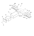
図2は、配置機構60の説明図である。配置機構60は、第1光学系31の第1光軸N上に、第1光学素子33および第2光学素子34の一方を選択的に配置する。配置機構60としては、例えば、第1光学素子33を保持する第1保持部材61と、第2光学素子34を保持する第2保持部材62と、第1保持部材61を移動させる第1移動機構66および第2保持部材62を移動させる第2移動機構67と、を備えるものとすることができる。第1移動機構66は、第1光学素子33が第1光学系31の第1光軸N上に位置する第1選択位置66Aと、第1光学素子33が第1光学系31の第1光軸Nから離間する第1退避位置66Bとの間で第1保持部材61を移動させる。第2移動機構67は、第2光学素子34が第1光学系31の第1光軸N上に位置する第2選択位置67Aと、第2光学素子34が第1光学系31の第1光軸Nから離間する第2退避位置67Bとの間で第2保持部材62を移動させる。第1選択位置66Aと第2選択位置67Aとは、第1光学系31の第1光軸方向の位置が相違する場合がある。第1保持部材61が第1選択位置66Aにある場合には、第2保持部材62は第2退避位置67Bに配置される。第2保持部材62が第2選択位置67Aにある場合には、第1保持部材61は第1退避位置66Bに配置される。第1移動機構66と第2移動機構67とは、連動して動作する。
FIG. 2 is an explanatory diagram of the
各実施例1~3の投写光学系の説明では、第2光学系32に第1光学素子33を選択した第1形態と、第2光学系32に第2光学素子34を選択した第2形態と、を並列に示す。また、各実施例1~3において、各投写光学系の光線図では、液晶パネル18R、液晶パネル18G、液晶パネル18Bを、液晶パネル18として表す。
In the description of the projection optical systems of Examples 1 to 3, a first embodiment in which the first optical element 33 is selected as the second optical system 32 and a second embodiment in which the second optical element 34 is selected as the second optical system 32 are described. and are shown in parallel. Further, in each of Examples 1 to 3, in the ray diagram of each projection optical system, the
(実施例1)
図3は、実施例1の第1形態の投写光学系3Aの全体を模式的に表す光線図である。図4は、実施例1の投写光学系3Aの第1形態の光線図である。図5は、実施例1の投写光学系3Aの第1形態における第2光学系の光線図である。図6は、実施例1の第2形態の投写光学系3Aの全体を模式的に表す光線図である。図7は、実施例1の第2形態の投写光学系3Aの光線図である。図8は、実施例1の投写光学系3Aの第2形態における第2光学系の光線図である。
(Example 1)
FIG. 3 is a ray diagram schematically showing the entire projection optical system 3A of the first embodiment of the first embodiment. FIG. 4 is a ray diagram of the first embodiment of the projection optical system 3A of the first embodiment. FIG. 5 is a ray diagram of the second optical system in the first form of the projection optical system 3A of Example 1. FIG. 6 is a ray diagram schematically showing the entire projection optical system 3A of the second embodiment of the first embodiment. FIG. 7 is a ray diagram of the projection optical system 3A of the second embodiment of the first embodiment. FIG. 8 is a ray diagram of the second optical system in the second form of the projection optical system 3A of Example 1.
図3に示すように、第1形態の投写光学系3Aは、広角投影が可能である。すなわち、第1形態の投写光学系3Aが最終像をスクリーンSに投写する投写角度である第1投写角度θ1は、比較的広い。図3および図6では、本例の投写光学系3AからスクリーンSに到達する光束を、光束F1~F3により模式的に示す。光束F1は最も像高が低い位置に達する光束である。光束F3は最も像高が高い位置に達する光束である。光束F2は光束F1と光束F3との間の位置に達する光束である。ここで、投写角度とは、第1光学系31の第1光軸Nと光束F3の最外郭の光線とが成す角度である。
As shown in FIG. 3, the projection optical system 3A of the first form is capable of wide-angle projection. That is, the first projection angle θ1, which is the projection angle at which the projection optical system 3A of the first form projects the final image onto the screen S, is relatively wide. In FIGS. 3 and 6, the light fluxes reaching the screen S from the projection optical system 3A of this example are schematically shown by light fluxes F1 to F3. The light flux F1 is the light flux that reaches the position where the image height is lowest. The light flux F3 is the light flux that reaches the position with the highest image height. The light flux F2 is a light flux that reaches a position between the light fluxes F1 and F3. Here, the projection angle is the angle formed by the first optical axis N of the first
(実施例1の第1形態)
第1形態の投写光学系3Aは、図4に示すように、縮小側から拡大側に向かって順に、第1光学系31、および第2光学系32からなる。第1光学系31は、複数枚のレンズを備える屈折光学系である。第2光学系32は第1光学素子33からなる。第1光学素子33は、縮小側から順に、第1入射面41、第1反射面42、および第1射出面43を有する。第1入射面41は、縮小側に突出する凸形状である。第1反射面42は凹形状を備える。第1射出面43は、拡大側に突出する凸形状である。第2光学系32を構成する第1光学素子33は、第1光学系31の第1光軸N上に配置される。本例では、第1光学系31の第1光軸Nと第1光学素子33の第1反射面42の第2光軸Mとは一致する。
(First form of Example 1)
As shown in FIG. 4, the projection optical system 3A of the first form includes a first
投写光学系3Aの縮小側結像面には、画像形成部2の液晶パネル18が配置されている。液晶パネル18は、第1光学系31の第1光軸Nに垂直な面内に、第1光軸Nに対して一方側に投写画像を形成する。投写光学系3Aの拡大側結像面には、スクリーンSが配置されている。第1光学系31と第1光学素子33の第1反射面42との間には、縮小側結像面と共役な中間像35が結像される。中間像35は拡大側結像面とも共役である。本例では、中間像35は、第1光学素子33の内側に形成される。すなわち、中間像35は、第1光学素子33の第1入射面41と第1反射面42との間に形成される。
The
以下の説明では、便宜上、互いに直交する3軸をX軸、Y軸(第1軸)、およびZ軸とする。また、拡大側結像面であるスクリーンSの幅方向をX軸方向、スクリーンSの上下方向をY軸方向、スクリーンSと垂直な方向をZ軸方向とする。また、第1光学系31の第1光軸Nおよび第1光学素子の第1反射面42の第2光軸Mを含む平面をYZ平面とする。
In the following description, for convenience, three mutually orthogonal axes are referred to as the X axis, the Y axis (first axis), and the Z axis. Further, the width direction of the screen S, which is the magnification-side imaging surface, is the X-axis direction, the vertical direction of the screen S is the Y-axis direction, and the direction perpendicular to the screen S is the Z-axis direction. Further, a plane including the first optical axis N of the first
本例では、第1光学系31の第1光軸N、および、第1光学素子33の第1反射面42の第2光軸Mは、Z軸方向に延びる。図3、図4、図5は、YZ平面上の光線図である。液晶パネル18は、第1光学系31の第1光軸Nの上方Y1に投写画像を形成する。
In this example, the first optical axis N of the first
図4に示すように、第1光学系31は、クロスダイクロイックプリズム19と、14枚のレンズL1~L14を有する。レンズL1~レンズL14は縮小側から拡大側に向かってこの順に配置されている。本例では、レンズL2とレンズL3は接合された第1接合レンズL21である。レンズL4とレンズL5は、接合された第2接合レンズL22である。レンズL9とレンズL10は接合された第3接合レンズL23である。レンズL7とレンズL8との間には、絞りOが配置されている。
As shown in FIG. 4, the first
図5に示すように、第1光学素子33は、第1反射面42の第2光軸Mを設計軸として設計されている。言い換えれば、第2光軸Mは、第1入射面41、第1射出面43および第1反射面42の設計上の光軸である。第1入射面41および第1反射面42は、第1反射面42の第2光軸Mの下方Y2に位置し、第1射出面43は、第1反射面42の第2光軸Mの上方Y1に位置する。本例では、第1光学素子33の第1入射面41、第1反射面42、および第1射出面43は、第1反射面42の第2光軸Mを回転軸として回転対称な形状を備える。従って、第1入射面41と第1射出面43とは回転対称な形状を備える。第1光学素子33の第1入射面41、第1反射面42および第1射出面43は、いずれも非球面である。第1反射面42は、第1光学素子33の第1入射面41とは反対側の面に設けた反射コーティング層である。なお、各非球面は、自由曲面の場合がある。この場合でも、自由曲面は、第2光軸Mを設計軸として設計されている。 As shown in FIG. 5, the first optical element 33 is designed with the second optical axis M of the first reflective surface 42 as a design axis. In other words, the second optical axis M is the designed optical axis of the first incident surface 41, the first exit surface 43, and the first reflective surface 42. The first incident surface 41 and the first reflective surface 42 are located below the second optical axis M of the first reflective surface 42, and the first exit surface 43 is located below the second optical axis M of the first reflective surface 42. Located above Y1. In this example, the first incident surface 41, first reflective surface 42, and first exit surface 43 of the first optical element 33 have shapes that are rotationally symmetrical about the second optical axis M of the first reflective surface 42. Be prepared. Therefore, the first entrance surface 41 and the first exit surface 43 have rotationally symmetrical shapes. The first entrance surface 41, first reflection surface 42, and first exit surface 43 of the first optical element 33 are all aspherical surfaces. The first reflective surface 42 is a reflective coating layer provided on the surface of the first optical element 33 opposite to the first incident surface 41 . Note that each aspherical surface may be a free-form surface. Even in this case, the free-form surface is designed with the second optical axis M as the design axis.
図5に示すように、第2光学系32の第1瞳P1は、第1光学素子33の内側に位置する。YZ平面における第2光学系32の第1瞳P1は、第1射出面43の有効光線範囲50のY軸方向の上端を通過する上端光束51の上周辺光線51aおよび有効光線範囲50のY軸方向の下端を通過する下端光束52の上周辺光線52aがYZ平面上で交差する上側交点53と、上端光束51の下周辺光線51bおよび下端光束52の下周辺光線52bがYZ平面上で交差する下側交点54とを結ぶ線で規定される。第1瞳P1は、YZ平面上で第1反射面42の第2光軸Mと垂直な仮想垂直線Vに対して傾斜する。 As shown in FIG. 5, the first pupil P1 of the second optical system 32 is located inside the first optical element 33. The first pupil P1 of the second optical system 32 in the YZ plane is connected to the upper peripheral ray 51a of the upper end light beam 51 passing through the upper end of the effective ray range 50 of the first exit surface 43 in the Y-axis direction and the Y-axis of the effective ray range 50. The upper intersection point 53 where the upper peripheral ray 52a of the lower end luminous flux 52 that passes through the lower end of the direction intersects on the YZ plane, and the lower peripheral ray 51b of the upper end luminous flux 51 and the lower peripheral ray 52b of the lower end luminous flux 52 intersect on the YZ plane. It is defined by a line connecting the lower intersection point 54. The first pupil P1 is inclined with respect to a virtual vertical line V perpendicular to the second optical axis M of the first reflective surface 42 on the YZ plane.
(レンズデータ)
投写光学系3Aのレンズデータは以下のとおりである。面番号は、縮小側から拡大側に順番に付してある。符号は、レンズ、第1入射面、第1反射面、および第1射出面の符号である。レンズ、第1入射面、第1反射面、および第1射出面に対応しない面番号のデータはダミーデータである。Rは曲率半径である。Dは軸上面間隔である。Cはアパーチャー半径である。R、D、Cの単位はmmである。
(lens data)
The lens data of the projection optical system 3A is as follows. The surface numbers are assigned in order from the reduced side to the enlarged side. The symbols are those of the lens, the first entrance surface, the first reflection surface, and the first exit surface. Data of surface numbers that do not correspond to the lens, the first entrance surface, the first reflection surface, and the first exit surface are dummy data. R is the radius of curvature. D is the axial spacing. C is the aperture radius. The units of R, D, and C are mm.
符号 面番号 形状 R D 硝材 屈折/反射 C
18 0 球 無限 8.4859 屈折 0.0000
19 1 球 無限 30.1506 SBSL7_OHARA 屈折 12.6334
2 球 無限 5.0143 屈折 14.8167
3 球 無限 0.0000 屈折 15.3698
4 球 無限 0.0000 屈折 15.3698
5 球 無限 0.0000 屈折 15.3698
L1 6 球 65.3371 5.8874 497451.7695 屈折 15.5777
7 球 -49.6319 0.1000 屈折 15.5634
L2 8 球 66.3089 8.4225 489067.6221 屈折 14.7615
L3 9 球 -22.5098 1.0000 834805.4272 屈折 14.4598
10 球 -72.9598 0.1000 屈折 14.5180
L4 11 球 61.0285 7.0224 466237.7988 屈折 14.0323
L5 12 球 -26.3124 1.0000 840873.3029 屈折 13.7644
13 球 29.8875 0.1216 屈折 13.7143
L6 14 球 30.5660 5.8252 827375.2424 屈折 13.7450
15 球 -89.6876 0.4982 屈折 13.7512
L7 16 球 -61.5318 3.7335 512482.7396 屈折 13.7509
17 球 -26.8299 18.5003 屈折 13.5002
O 絞り 球 無限 12.1803 屈折 8.0653
L8 19 球 -19.3204 1.0000 437001.951 屈折 8.0001
20 球 -26.1014 20.1363 屈折 8.3250
L9 21 球 43.9622 19.2102 655112.3105 屈折 15.8061
L10 22 球 -21.3739 1.0000 846663.2378 屈折 16.0445
23 球 48.4377 1.2197 屈折 17.6763
L11 24 球 74.6611 11.4179 667614.3028 屈折 17.6787
25 球 -24.9813 0.1000 屈折 18.1297
L12 26 球 -28.0717 1.0000 776762.4909 屈折 17.8804
27 球 -218.8664 0.1000 屈折 19.5619
L13 28 非球面 35.5372 6.0001 E48R_ZEON 屈折 21.0899
29 非球面 62.2622 18.2764 屈折 21.9723
L14 30 非球面 -260.9712 6.0001 E48R_ZEON 屈折 24.5560
31 非球面 -242.0358 11.8538 屈折 25.5340
32 球 無限 0.0000 屈折 24.3112
41 33 非球面 56.3202 39.2342 Z330R_ZEON 屈折 23.9622
34 球 無限 0.0000 Z330R_ZEON 屈折 18.3502
42 35 非球面 -17.6860 0.0000 Z330R_ZEON 反射 19.1699
36 球 無限 -39.2342 Z330R_ZEON 屈折 37.2226
43 37 非球面 56.3202 -110.0018 屈折 33.0898
38 球 無限 -95.0015 屈折 513.9232
39 球 無限 -301.0048 屈折 873.4344
S 40 球 無限 0.0000 屈折 2012.5170
Code Surface number Shape RD Glass material Refraction/reflection C
18 0 Sphere Infinity 8.4859 Refraction 0.0000
19 1 Sphere Infinite 30.1506 SBSL7_OHARA Refraction 12.6334
2 Sphere Infinity 5.0143 Refraction 14.8167
3 Sphere Infinity 0.0000 Refraction 15.3698
4 Sphere Infinity 0.0000 Refraction 15.3698
5 Sphere Infinity 0.0000 Refraction 15.3698
7 Sphere -49.6319 0.1000 Refraction 15.5634
L2 8 Sphere 66.3089 8.4225 489067.6221 Refraction 14.7615
L3 9 sphere -22.5098 1.0000 834805.4272 Refraction 14.4598
10 Sphere -72.9598 0.1000 Refraction 14.5180
13 Sphere 29.8875 0.1216 Refraction 13.7143
15 Sphere -89.6876 0.4982 Refraction 13.7512
17 Sphere -26.8299 18.5003 Refraction 13.5002
O Aperture Sphere Infinity 12.1803 Refraction 8.0653
20 Sphere -26.1014 20.1363 Refraction 8.3250
23 Sphere 48.4377 1.2197 Refraction 17.6763
25 Sphere -24.9813 0.1000 Refraction 18.1297
L12 26 Sphere -28.0717 1.0000 776762.4909 Refraction 17.8804
27 Sphere -218.8664 0.1000 Refraction 19.5619
L13 28 Aspheric 35.5372 6.0001 E48R_ZEON Refraction 21.0899
29 Aspheric 62.2622 18.2764 Refraction 21.9723
L14 30 Aspheric -260.9712 6.0001 E48R_ZEON Refraction 24.5560
31 Aspheric -242.0358 11.8538 Refraction 25.5340
32 Sphere Infinity 0.0000 Refraction 24.3112
41 33 Aspheric 56.3202 39.2342 Z330R_ZEON Refraction 23.9622
34 Sphere Infinity 0.0000 Z330R_ZEON Refraction 18.3502
42 35 Aspheric -17.6860 0.0000 Z330R_ZEON Reflection 19.1699
36 Sphere Infinity -39.2342 Z330R_ZEON Refraction 37.2226
43 37 Aspheric 56.3202 -110.0018 Refraction 33.0898
38 Sphere Infinity -95.0015 Refraction 513.9232
39 Sphere Infinity -301.0048 Refraction 873.4344
S 40 Sphere Infinity 0.0000 Refraction 2012.5170
各非球面の非球面係数は以下のとおりである。 The aspherical coefficients of each aspherical surface are as follows.
面番号 S28 S29 S30 S31
Y曲率半径 35.5372 62.2622 -260.9712 -242.0358
コーニック定数(K) -0.133920864 -8.315740849 90 0
4次の係数(A) -1.01937E-05 -6.03735E-06 -1.01994E-05 -2.82320E-05
6次の係数(B) -8.03197E-09 -2.41061E-08 -2.81612E-08 1.83126E-08
8次の係数(C) -3.19987E-11 5.87667E-13 3.19894E-11 -1.52624E-11
10次の係数(D)
12次の係数(E)
Surface number S28 S29 S30 S31
Y radius of curvature 35.5372 62.2622 -260.9712 -242.0358
Conic constant (K) -0.133920864 -8.315740849 90 0
Fourth order coefficient (A) -1.01937E-05 -6.03735E-06 -1.01994E-05 -2.82320E-05
6th order coefficient (B) -8.03197E-09 -2.41061E-08 -2.81612E-08 1.83126E-08
8th order coefficient (C) -3.19987E-11 5.87667E-13 3.19894E-11 -1.52624E-11
10th order coefficient (D)
12th order coefficient (E)
面番号 S33 S35 S37
Y曲率半径 56.3202 -17.6860 56.3202
コーニック定数(K) 1.649968721 -3.245671782 1.649968721
4次の係数(A) 4.94475E-07 -4.92801E-06 4.94475E-07
6次の係数(B) 2.03014E-09 1.05751E-08 2.03014E-09
8次の係数(C) -1.01723E-12 -8.36427E-12 -1.01723E-12
10次の係数(D) -9.62950E-16 1.90974E-14 -9.62950E-16
12次の係数(E) 1.00490E-18 1.00490E-18
Surface number S33 S35 S37
Y radius of curvature 56.3202 -17.6860 56.3202
Conic constant (K) 1.649968721 -3.245671782 1.649968721
Fourth order coefficient (A) 4.94475E-07 -4.92801E-06 4.94475E-07
6th order coefficient (B) 2.03014E-09 1.05751E-08 2.03014E-09
8th order coefficient (C) -1.01723E-12 -8.36427E-12 -1.01723E-12
10th order coefficient (D) -9.62950E-16 1.90974E-14 -9.62950E-16
12th order coefficient (E) 1.00490E-18 1.00490E-18
また、第1形態の投写光学系3Aの最大物体高、Fナンバー、投写角度、TRは、以下のとおりである。最大物体高は、液晶パネル18面上において画像形成領域の中で、第1形態の投写光学系3Aの第1光軸Nから最も離れた点までの寸法である。最大物体高の単位はmmである。FナンバーはFNOで示す。投写角度は、第1投写角度θ1であり、単位はdegである。TRは、スローレシオであり、投写距離を、投写画像をスクリーンSへ投写した時のX軸方向の寸法で除算した値である。
最大物体高 11.7
FNO 2.2
投写角度 75.3
TR(0.59”16:9LV) 0.230
Further, the maximum object height, F number, projection angle, and TR of the projection optical system 3A of the first form are as follows. The maximum object height is the dimension from the first optical axis N of the projection optical system 3A of the first form to the farthest point in the image forming area on the surface of the
Maximum object height 11.7
FNO 2.2
Projection angle 75.3
TR (0.59”16:9LV) 0.230
(実施例1の第2形態)
図3および図6に示すように、第2形態の投写光学系3Aが最終像をスクリーンSに投写する投写角度である第2投写角度θ2は、第1形態の投写光学系3Aが最終像をスクリーンSに投写する第1投写角度θ1と比較して、狭い。
(Second form of Example 1)
As shown in FIGS. 3 and 6, the second projection angle θ2, which is the projection angle at which the projection optical system 3A of the second form projects the final image onto the screen S, is the projection angle at which the projection optical system 3A of the first form projects the final image. It is narrower than the first projection angle θ1 for projecting onto the screen S.
第2形態の投写光学系3Aは、図7に示すように、縮小側から拡大側に向かって順に、第1光学系31、および第2光学系32からなる。第2光学系32は第2光学素子34からなる。第2光学素子34は、縮小側から順に、第2入射面46、第2反射面47、および第2射出面48を有する。第2入射面46は、縮小側に突出する凸形状である。第2反射面47は凹形状を備える。第2射出面48は、拡大側に突出する凸形状である。第2光学系32を構成する第2光学素子34は、第1光学系31の第1光軸N上に配置される。本例では、第1光学系31の第1光軸Nと第2反射面47の第2光軸Mとは一致する。第1光学系31は、第1形態の投写光学系と同一である。液晶パネル18の配置も第1形態の投写光学系と同一である。
As shown in FIG. 7, the projection optical system 3A of the second form includes a first
第1光学系31と第2光学素子34の第2反射面47との間には、縮小側結像面と共役な中間像35が結像される。中間像35は拡大側結像面とも共役である。中間像35は、第2光学素子34の内側に形成される。すなわち、中間像35は、第2光学素子34の第2入射面46と第2反射面47との間に形成される。
An intermediate image 35 that is conjugate with the reduction side imaging plane is formed between the first
図8に示すように、第2光学素子34は、第2反射面47の第2光軸Mを設計軸として設計されている。言い換えれば、第2光軸Mは、第2入射面46、第2射出面48および第2反射面47の設計上の光軸である。第2入射面46および第2反射面47は、第2反射面47の第2光軸Mの下方Y2に位置し、第2射出面48は、第2反射面47の第2光軸Mの上方Y1に位置する。本例では、第2光学素子34の第2入射面46、第2反射面47、および第2射出面48は、第2反射面47の第2光軸Mを回転軸として回転対称な形状を備える。従って、第2入射面46と第2射出面48とは回転対称な形状を備える。第2光学素子34の第2入射面46、第2反射面47および第2射出面48は、いずれも非球面である。第2反射面47は、第2光学素子34の第2入射面46とは反対側の面に設けた反射コーティング層である。なお、各非球面は、自由曲面の場合がある。この場合でも、自由曲面は、第2光軸Mを設計軸として設計されている。 As shown in FIG. 8, the second optical element 34 is designed with the second optical axis M of the second reflective surface 47 as a design axis. In other words, the second optical axis M is the designed optical axis of the second entrance surface 46, the second exit surface 48, and the second reflection surface 47. The second incident surface 46 and the second reflective surface 47 are located below the second optical axis M of the second reflective surface 47, and the second exit surface 48 is located below the second optical axis M of the second reflective surface 47. Located above Y1. In this example, the second entrance surface 46, second reflection surface 47, and second exit surface 48 of the second optical element 34 have shapes that are rotationally symmetrical about the second optical axis M of the second reflection surface 47. Be prepared. Therefore, the second entrance surface 46 and the second exit surface 48 have rotationally symmetrical shapes. The second entrance surface 46, second reflection surface 47, and second exit surface 48 of the second optical element 34 are all aspherical surfaces. The second reflective surface 47 is a reflective coating layer provided on the surface of the second optical element 34 opposite to the second incident surface 46 . Note that each aspherical surface may be a free-form surface. Even in this case, the free-form surface is designed with the second optical axis M as the design axis.
図9は、第1光学素子33と第2光学素子34との形状の相違の説明図である。図9では、第1光学素子33と第2光学素子34とを重ねた場合を示す。図9に示すように、第1光学素子33の第1入射面41、第1反射面42、および第1射出面43の形状と、第2光学素子34の第2入射面46、第2反射面47、および第2射出面48のそれぞれの形状とが、互いに相違する。すなわち、第2光学素子34の第2入射面46の非球面形状は、第1光学素子33の第1入射面41と相違する。第2光学素子34の第2反射面47の非球面形状は、第1光学素子33の第1反射面42と相違する。第2光学素子34の第2射出面48の非球面形状は、第1光学素子33の第1射出面43と相違する。また、第1光学素子33において、第1反射面42で反射された第1光束の主光線が第1射出面43に入射する第1入射角度は、第2光学素子34において、第2反射面47で反射された第2光束の主光線が第2射出面48に入射する第2入射角度よりも大きい。 FIG. 9 is an explanatory diagram of the difference in shape between the first optical element 33 and the second optical element 34. FIG. 9 shows a case where the first optical element 33 and the second optical element 34 are overlapped. As shown in FIG. 9, the shapes of the first entrance surface 41, first reflection surface 42, and first exit surface 43 of the first optical element 33, and the shapes of the second entrance surface 46 and the second reflection surface of the second optical element 34 are shown. The shapes of the surface 47 and the second exit surface 48 are different from each other. That is, the aspherical shape of the second entrance surface 46 of the second optical element 34 is different from the first entrance surface 41 of the first optical element 33 . The aspherical shape of the second reflective surface 47 of the second optical element 34 is different from the first reflective surface 42 of the first optical element 33 . The aspherical shape of the second exit surface 48 of the second optical element 34 is different from the first exit surface 43 of the first optical element 33 . Further, in the first optical element 33, the first incident angle at which the principal ray of the first luminous flux reflected by the first reflective surface 42 is incident on the first exit surface 43 is the same as that of the second reflective surface in the second optical element 34. The principal ray of the second light beam reflected at 47 is larger than the second incident angle at which it enters the second exit surface 48 .
図8に示すように、第2光学系32の第2瞳P2は、第2光学素子34の内側に位置する。YZ平面における第2光学系32の第2瞳P2は、第2射出面48の有効光線範囲50のY軸方向の上端を通過する上端光束51の上周辺光線51aおよび有効光線範囲50のY軸方向の下端を通過する下端光束52の上周辺光線52aがYZ平面上で交差する上側交点53と、上端光束51の下周辺光線51bおよび下端光束52の下周辺光線52bがYZ平面上で交差する下側交点54とを結ぶ線で規定されるものである。第2瞳P2は、YZ平面上で第2反射面47の第2光軸Mと垂直な仮想垂直線Vに対して傾斜する。 As shown in FIG. 8, the second pupil P2 of the second optical system 32 is located inside the second optical element 34. The second pupil P2 of the second optical system 32 in the YZ plane is the upper peripheral ray 51a of the upper end light beam 51 passing through the upper end of the effective ray range 50 of the second exit surface 48 in the Y-axis direction and the Y-axis of the effective ray range 50. The upper intersection point 53 where the upper peripheral ray 52a of the lower end luminous flux 52 that passes through the lower end of the direction intersects on the YZ plane, and the lower peripheral ray 51b of the upper end luminous flux 51 and the lower peripheral ray 52b of the lower end luminous flux 52 intersect on the YZ plane. It is defined by a line connecting the lower intersection point 54. The second pupil P2 is inclined with respect to a virtual vertical line V perpendicular to the second optical axis M of the second reflective surface 47 on the YZ plane.
(レンズデータ)
第2形態の投写光学系3Aでは、第1光学系31のレンズL14と第2光学素子34との軸上面間距離である第2距離と、第1形態の投写光学系3Aの第1光学系31のレンズL14と第1光学素子33との軸上面間距離である第1距離とは相違する。すなわち、本例の投写光学系では、配置機構60は、第1光学素子33と第2光学素子34とを、第1光学系31の第1光軸N上において、異なる位置に配置する。第2形態の投写光学系3Aのレンズデータは以下のとおりである。面番号は、縮小側から拡大側に順番に付してある。符号は、レンズ、第2入射面、第2反射面、および第2射出面の符号である。レンズ、第2入射面、第2反射面、および第2射出面に対応しない面番号のデータはダミーデータである。Rは曲率半径である。Dは軸上面間隔である。Cはアパーチャー半径である。R、D、Cの単位はmmである。
(lens data)
In the projection optical system 3A of the second form, the second distance, which is the distance between the axial surfaces of the lens L14 of the first
符号 面番号 形状 R D 硝材 屈折/反射 C
18 0 球 無限 8.4859 屈折 0.0000
19 1 球 無限 30.1506 SBSL7_OHARA 屈折 12.6334
2 球 無限 5.0143 屈折 14.8167
3 球 無限 0.0000 屈折 15.3698
4 球 無限 0.0000 屈折 15.3698
5 球 無限 0.0000 屈折 15.3698
L1 6 球 65.3371 5.8874 497451.7695 屈折 15.5777
7 球 -49.6319 0.1000 屈折 15.5634
L2 8 球 66.3089 8.4225 489067.6221 屈折 14.7615
L3 9 球 -22.5098 1.0000 834805.4272 屈折 14.4598
10 球 -72.9598 0.1000 屈折 14.5180
L4 11 球 61.0285 7.0224 466237.7988 屈折 14.0323
L5 12 球 -26.3124 1.0000 840873.3029 屈折 13.7644
13 球 29.8875 0.1216 屈折 13.7143
L6 14 球 30.5660 5.8252 827375.2424 屈折 13.7450
15 球 -89.6876 0.4982 屈折 13.7512
L7 16 球 -61.5318 3.7335 512482.7396 屈折 13.7509
17 球 -26.8299 18.5003 屈折 13.5002
O1 絞り 球 無限 12.1803 屈折 8.0653
L8 19 球 -19.3204 1.0000 437001.951 屈折 8.0001
20 球 -26.1014 20.1363 屈折 8.3250
L9 21 球 43.9622 19.2102 655112.3105 屈折 15.8061
L10 22 球 -21.3739 1.0000 846663.2378 屈折 16.0445
23 球 48.4377 1.2197 屈折 17.6763
L11 24 球 74.6611 11.4179 667614.3028 屈折 17.6787
25 球 -24.9813 0.1000 屈折 18.1297
L12 26 球 -28.0717 1.0000 776762.4909 屈折 17.8804
27 球 -218.8664 0.1000 屈折 19.5619
L13 28 非球面 35.5372 6.0001 E48R_ZEON 屈折 21.0899
29 非球面 62.2622 18.2764 屈折 21.9723
L14 30 非球面 -260.9712 6.0001 E48R_ZEON 屈折 24.5560
31 非球面 -242.0358 11.0000 屈折 25.5340
32 球 無限 0.0000 屈折 24.3112
46 33 非球面 43.3299 39.2342 Z330R_ZEON 屈折 23.9622
34 球 無限 0.0000 Z330R_ZEON 屈折 18.3502
47 35 非球面 -20.7986 0.0000 Z330R_ZEON 反射 19.1699
36 球 無限 -39.2342 Z330R_ZEON 屈折 37.2226
48 37 非球面 43.3299 -110.0018 屈折 33.0898
38 球 無限 -95.0015 屈折 513.9232
39 球 無限 -301.0048 屈折 873.4344
S 40 球 無限 0.0000 屈折 2012.5170
Code Surface number Shape RD Glass material Refraction/reflection C
18 0 Sphere Infinity 8.4859 Refraction 0.0000
19 1 Sphere Infinite 30.1506 SBSL7_OHARA Refraction 12.6334
2 Sphere Infinity 5.0143 Refraction 14.8167
3 Sphere Infinity 0.0000 Refraction 15.3698
4 Sphere Infinity 0.0000 Refraction 15.3698
5 Sphere Infinity 0.0000 Refraction 15.3698
7 Sphere -49.6319 0.1000 Refraction 15.5634
L2 8 Sphere 66.3089 8.4225 489067.6221 Refraction 14.7615
L3 9 sphere -22.5098 1.0000 834805.4272 Refraction 14.4598
10 Sphere -72.9598 0.1000 Refraction 14.5180
13 Sphere 29.8875 0.1216 Refraction 13.7143
15 Sphere -89.6876 0.4982 Refraction 13.7512
17 Sphere -26.8299 18.5003 Refraction 13.5002
O1 Aperture Sphere Infinity 12.1803 Refraction 8.0653
20 Sphere -26.1014 20.1363 Refraction 8.3250
23 Sphere 48.4377 1.2197 Refraction 17.6763
25 Sphere -24.9813 0.1000 Refraction 18.1297
L12 26 Sphere -28.0717 1.0000 776762.4909 Refraction 17.8804
27 Sphere -218.8664 0.1000 Refraction 19.5619
L13 28 Aspheric 35.5372 6.0001 E48R_ZEON Refraction 21.0899
29 Aspheric 62.2622 18.2764 Refraction 21.9723
L14 30 Aspheric -260.9712 6.0001 E48R_ZEON Refraction 24.5560
31 Aspheric -242.0358 11.0000 Refraction 25.5340
32 Sphere Infinity 0.0000 Refraction 24.3112
46 33 Aspheric 43.3299 39.2342 Z330R_ZEON Refraction 23.9622
34 Sphere Infinity 0.0000 Z330R_ZEON Refraction 18.3502
47 35 Aspheric -20.7986 0.0000 Z330R_ZEON Reflection 19.1699
36 Sphere Infinity -39.2342 Z330R_ZEON Refraction 37.2226
48 37 Aspheric 43.3299 -110.0018 Refraction 33.0898
38 Sphere Infinity -95.0015 Refraction 513.9232
39 Sphere Infinity -301.0048 Refraction 873.4344
S 40 Sphere Infinity 0.0000 Refraction 2012.5170
第2光学素子34の各非球面の非球面係数は以下のとおりである。 The aspherical coefficients of each aspherical surface of the second optical element 34 are as follows.
面番号 S33 S35 S37
Y曲率半径 43.3299 -20.7986 43.3299
コーニック定数(K) 0.784834378 -3.517637827 0.784834378
4次の係数(A) -4.89548E-07 -1.03308E-05 -4.89548E-07
6次の係数(B) -6.28825E-09 3.81030E-08 -6.28825E-09
8次の係数(C) 1.27262E-11 -5.78676E-11 1.27262E-11
10次の係数(D) -8.63796E-15 5.74521E-14 -8.63796E-15
12次の係数(E) 2.12690E-18 2.12690E-18
Surface number S33 S35 S37
Y radius of curvature 43.3299 -20.7986 43.3299
Conic constant (K) 0.784834378 -3.517637827 0.784834378
Fourth order coefficient (A) -4.89548E-07 -1.03308E-05 -4.89548E-07
6th coefficient (B) -6.28825E-09 3.81030E-08 -6.28825E-09
8th order coefficient (C) 1.27262E-11 -5.78676E-11 1.27262E-11
10th order coefficient (D) -8.63796E-15 5.74521E-14 -8.63796E-15
12th order coefficient (E) 2.12690E-18 2.12690E-18
また、第2形態の投写光学系3Aの最大物体高、Fナンバー、投写角度、TRは、以下のとおりである。最大物体高は、液晶パネル18面上において画像形成領域の中で、第2形態の投写光学系3Aの第1光軸Nから最も離れた点までの寸法である。最大物体高の単位はmmである。FナンバーはFNOで示す。投写角度は、第2投写角度θ2であり、単位はdegである。TRは、スローレシオであり、投写距離を、投写画像をスクリーンSへ投写した時のX軸方向の寸法で除算した値である。
最大物体高 11.7
FNO 2.2
投写角度 70.9
TR(0.59”16:9LV) 0.304
Moreover, the maximum object height, F number, projection angle, and TR of the projection optical system 3A of the second embodiment are as follows. The maximum object height is the dimension from the first optical axis N of the projection optical system 3A of the second embodiment to the point farthest from the image forming area on the surface of the
Maximum object height 11.7
FNO 2.2
Projection angle 70.9
TR (0.59”16:9LV) 0.304
(作用効果)
本例の投写光学系3Aは、縮小側から拡大側に向かって順に、第1光学系31と、第2光学系32と、を備える。また、投写光学系3Aは、縮小側から順に、第1入射面41と、第1反射面42と、第1射出面43と、を有する第1光学素子33と、縮小側から順に、第2入射面46と、第2反射面47と、第2射出面48と、を有する第2光学素子34と、を有し、第2光学系32には、第1光学素子33、または第2光学素子34の一方が交換可能に配置される。また、投写光学系3Aは、第1光学素子33、または第2光学素子34の一方を、第2光学系32に選択的に配置する配置機構60を備える。
(effect)
The projection optical system 3A of this example includes a first
従って、本例の投写光学系3Aは、第2光学系32に第1光学素子33および第2光学素子34のいずれが選択された場合でも、反射面で反射した光束を、射出面で屈折させることができる。よって、第2光学系が、反射面のみを備える場合と比較して、投写光学系の投写距離を短くすることが容易である。言い換えれば、本例の投写光学系3Aは、第2光学系が反射面のみを備える場合と比較して、投写光学系を短焦点化することができる。 Therefore, the projection optical system 3A of this example refracts the light beam reflected on the reflective surface at the exit surface, regardless of which of the first optical element 33 and the second optical element 34 is selected for the second optical system 32. be able to. Therefore, compared to the case where the second optical system includes only a reflective surface, it is easier to shorten the projection distance of the projection optical system. In other words, the projection optical system 3A of this example can shorten the focus of the projection optical system compared to the case where the second optical system includes only a reflective surface.
また、本例では、第2光学系32に第1光学素子33が配置された場合の投写角度を第1投写角度θ1とし、第2光学系32に第2光学素子34が配置された場合の投写角度を第2投写角度θ2とした場合に、第1投写角度θ1と第2投写角度θ2とは相違する。すなわち、本例では、第2光学系32に第1光学素子33を選択した場合と、第2光学素子34を選択した場合とで、投写光学系3Aの投写角度を変化させることができる。ここで、従来は、投写角度を変えるためには、投写光学系の全体を交換する必要があった。これに対して、本例の投写光学系3Aによれば、予め備える2つの第2光学系32を選択的に配置するだけで、投写角度を変更できる。よって、レンズ交換のコストを抑制しながら、プロジエクターの投写角度を変更できる。 Furthermore, in this example, the projection angle when the first optical element 33 is arranged in the second optical system 32 is the first projection angle θ1, and the projection angle when the second optical element 34 is arranged in the second optical system 32 is the first projection angle θ1. When the projection angle is the second projection angle θ2, the first projection angle θ1 and the second projection angle θ2 are different. That is, in this example, the projection angle of the projection optical system 3A can be changed depending on whether the first optical element 33 is selected as the second optical system 32 or the second optical element 34 is selected. Here, conventionally, in order to change the projection angle, it was necessary to replace the entire projection optical system. On the other hand, according to the projection optical system 3A of this example, the projection angle can be changed simply by selectively arranging the two second optical systems 32 provided in advance. Therefore, the projection angle of the projector can be changed while suppressing the cost of lens replacement.
さらに、本例では、第2光学系32に第1光学素子33を選択した場合でも、第2光学素子34を選択した場合でも、第1光学系31は共通である。すなわち、第1光学系は1つである。従って、投写角度の変更にかかるコストを抑制できる。
Furthermore, in this example, the first
また、第1形態の投写光学系3Aにおいて、第1光学素子33は拡大側に突出する凸形状の第1射出面43を備えるので、第1射出面43において光束を屈折させることができる。従って、拡大側結像面であるスクリーンSと共役となる中間像35が、第1反射面42の第2光軸Mに沿って傾斜して大きくなることを抑制できる。よって、中間像35の拡大側に位置する第1反射面42が大型化することを抑制できる。同様に、第2形態の投写光学系3Aにおいて、第2光学素子34は拡大側に突出する凸形状の第2射出面48を備えるので、第2射出面48において光束を屈折させることができる。従って、拡大側結像面であるスクリーンSと共役となる中間像35が、第2反射面47の第2光軸Mに沿って傾斜して大きくなることを抑制できる。よって、中間像35の拡大側に位置する第2反射面47が大型化することを抑制できる。 Further, in the projection optical system 3A of the first embodiment, the first optical element 33 includes the first exit surface 43 having a convex shape that projects toward the enlargement side, so that the light beam can be refracted at the first exit surface 43. Therefore, it is possible to prevent the intermediate image 35 that is conjugate with the screen S, which is the magnification-side image formation surface, from tilting and increasing along the second optical axis M of the first reflective surface 42 . Therefore, it is possible to suppress the first reflecting surface 42 located on the enlarged side of the intermediate image 35 from increasing in size. Similarly, in the second embodiment of the projection optical system 3A, the second optical element 34 includes a convex second exit surface 48 that projects toward the enlargement side, so that the second exit surface 48 can refract the light beam. Therefore, it is possible to prevent the intermediate image 35 that is conjugate with the screen S, which is the magnification-side image formation surface, from tilting and increasing along the second optical axis M of the second reflective surface 47. Therefore, it is possible to suppress the second reflective surface 47 located on the enlarged side of the intermediate image 35 from increasing in size.
また、第1光学素子33では、第1入射面41、第1反射面42、および第1射出面43が、第1反射面42の第2光軸Mを回転軸として回転対称な形状を備える。従って、第1光学素子33の製造が容易である。また、第1光学素子33が回転対称な形状を備えるので、第1光学素子33が回転対称な形状ではない場合と比較して、製造時における第1光学素子33の歩留まりが向上する。同様に、第2光学素子34では、第2入射面46、第2反射面47、および第2射出面48が、第2反射面47の第2光軸Mを回転軸として回転対称な形状を備える。従って、第2光学素子34の製造が容易である。また、第2光学素子34が回転対称な形状を備えるので、第2光学素子34が回転対称な形状ではない場合と比較して、製造時における第2光学素子の歩留まりが向上する。 Furthermore, in the first optical element 33, the first incident surface 41, the first reflective surface 42, and the first exit surface 43 have shapes that are rotationally symmetrical about the second optical axis M of the first reflective surface 42 as a rotation axis. . Therefore, manufacturing of the first optical element 33 is easy. Further, since the first optical element 33 has a rotationally symmetrical shape, the yield of the first optical element 33 during manufacturing is improved compared to a case where the first optical element 33 does not have a rotationally symmetrical shape. Similarly, in the second optical element 34, the second entrance surface 46, the second reflection surface 47, and the second exit surface 48 have shapes that are rotationally symmetrical about the second optical axis M of the second reflection surface 47. Be prepared. Therefore, manufacturing of the second optical element 34 is easy. Further, since the second optical element 34 has a rotationally symmetrical shape, the yield of the second optical element during manufacturing is improved compared to a case where the second optical element 34 does not have a rotationally symmetrical shape.
ここで、第2光学系32に第1光学素子33を選択した場合でも、第2光学素子34を選択した場合でも、第2光学系32の瞳P(第1瞳P1および第2瞳P2)は、第1反射面42および第2反射面47の第2光軸Mと垂直な仮想垂直線Vに対して傾斜している。従って、第2光学系32の瞳Pが仮想垂直線Vと平行な場合と比較して、スクリーンSの上方Y1の周辺部の光量が低下することを抑制できる。すなわち、瞳Pが仮想垂直線Vに対して傾斜すれば、瞳Pが仮想垂直線Vと平行な場合と比較して、スクリーンSの上部へ達する光束F1の光量が多くなる。また、スクリーンSの上部へ達する光束F1の光量が多くなれば、スクリーンSの下部へ達する光束F3の光量との差が小さくなる。従って、スクリーンSの上部の周辺部の光量が、下部と比較して低下することを抑制できる。 Here, whether the first optical element 33 is selected as the second optical system 32 or the second optical element 34 is selected, the pupil P (first pupil P1 and second pupil P2) of the second optical system 32 is inclined with respect to an imaginary vertical line V perpendicular to the second optical axis M of the first reflective surface 42 and the second reflective surface 47. Therefore, compared to the case where the pupil P of the second optical system 32 is parallel to the virtual vertical line V, it is possible to suppress a decrease in the amount of light in the peripheral portion above Y1 of the screen S. That is, if the pupil P is inclined with respect to the virtual vertical line V, the amount of light flux F1 reaching the upper part of the screen S will be greater than when the pupil P is parallel to the virtual vertical line V. Further, as the amount of light F1 reaching the upper part of the screen S increases, the difference from the amount of light F3 reaching the lower part of the screen S becomes smaller. Therefore, the amount of light in the upper peripheral part of the screen S can be suppressed from decreasing compared to the lower part.
さらに、本例では、第1光学素子33において、中間像35の縮小側に位置する第1入射面41が非球面なので、中間像35での収差の発生を抑制できる。また、第1光学素子33の第1反射面42、および第1射出面43は、非球面である。従って、拡大側結像面において、収差の発生を抑制できる。同様に、第2光学素子34において、中間像35の縮小側に位置する第2入射面46が非球面なので、中間像35での収差の発生を抑制できる。また、第2光学素子34の第2反射面47、および第2射出面48は、非球面である。従って、拡大側結像面において、収差の発生を抑制できる。 Furthermore, in this example, in the first optical element 33, the first entrance surface 41 located on the reduction side of the intermediate image 35 is an aspherical surface, so that the occurrence of aberrations in the intermediate image 35 can be suppressed. Further, the first reflective surface 42 and the first exit surface 43 of the first optical element 33 are aspherical surfaces. Therefore, it is possible to suppress the occurrence of aberrations on the magnification-side imaging plane. Similarly, in the second optical element 34, since the second entrance surface 46 located on the reduction side of the intermediate image 35 is an aspherical surface, the occurrence of aberrations in the intermediate image 35 can be suppressed. Further, the second reflective surface 47 and the second exit surface 48 of the second optical element 34 are aspherical surfaces. Therefore, it is possible to suppress the occurrence of aberrations on the magnification-side imaging plane.
また、本例では、第1光学素子33の第1入射面41、第1反射面42、および第1射出面43の形状と、第2光学素子34の第2入射面46、第2反射面47、および第2射出面48のそれぞれの形状とが、互いに相違する。従って、第1光学素子33と第2光学素子34とを選択的に配置したときに、投写光学系の投写角度を変更することが容易である。 In addition, in this example, the shapes of the first entrance surface 41, first reflection surface 42, and first exit surface 43 of the first optical element 33, and the shapes of the second entrance surface 46 and the second reflection surface of the second optical element 34 are 47 and the shapes of the second exit surface 48 are different from each other. Therefore, when the first optical element 33 and the second optical element 34 are selectively arranged, it is easy to change the projection angle of the projection optical system.
さらに、本例では、第1光学素子33において、第1反射面42で反射された第1光束の主光線が第1射出面43に入射する第1入射角度は、第2光学素子34において、第2反射面47で反射された第2光束の主光線が第2射出面48に入射する第2入射角度よりも大きい。このように配置することにより、第1形態の投写光学系3Aの第1投写角度θ1を、第2形態の投写光学系の第2投写角度θ2よりも大きくすることが可能となる。 Furthermore, in the present example, in the first optical element 33, the first incident angle at which the principal ray of the first light flux reflected by the first reflecting surface 42 is incident on the first exit surface 43 is, in the second optical element 34, The principal ray of the second light beam reflected by the second reflecting surface 47 is larger than the second incident angle at which it enters the second exit surface 48 . By arranging in this way, it becomes possible to make the first projection angle θ1 of the projection optical system 3A of the first form larger than the second projection angle θ2 of the projection optical system of the second form.
図10は、第1形態の投写光学系3Aの拡大側のMTFを示す図である。図11は、第2形態の投写光学系3Aの拡大側のMTFを示す図である。図10、図11において、横軸は空間周波数であり、縦軸はコントラスト再現比である。図10、図11において、黒色のグラフは、タンジェンシャル光線(T)を示し、灰色のグラフは、ラジアル光線(R)を示す。また、タンジェンシャル光線(T)およびラジアル光線(R)のそれぞれにおいて、実線は、光束F1であり、間隔の長い破線は、光束F2であり、破線は、光束F3である。図10、図11に示すように、本例の投写光学系3Aは、高い解像度を有する。 FIG. 10 is a diagram showing the MTF on the enlargement side of the projection optical system 3A of the first embodiment. FIG. 11 is a diagram showing the MTF on the enlargement side of the projection optical system 3A of the second embodiment. In FIGS. 10 and 11, the horizontal axis is the spatial frequency, and the vertical axis is the contrast reproduction ratio. In FIGS. 10 and 11, black graphs indicate tangential rays (T), and gray graphs indicate radial rays (R). Further, in each of the tangential light ray (T) and the radial light ray (R), the solid line is the light flux F1, the broken line with a long interval is the light flux F2, and the broken line is the light flux F3. As shown in FIGS. 10 and 11, the projection optical system 3A of this example has high resolution.
(実施例2)
図12は、実施例2の第1形態の投写光学系3Bの全体を模式的に表す光線図である。図13は、実施例2の投写光学系3Bの第1形態の光線図である。図14は、実施例2の投写光学系3Bの第1形態の第2光学系の光線図である。図15は、実施例2の第2形態の投写光学系3Bの全体を模式的に表す光線図である。図16は、実施例2の第2形態の投写光学系3Bの光線図である。図17は、実施例2の投写光学系3Bの第2光学系の光線図である。
(Example 2)
FIG. 12 is a ray diagram schematically showing the entire projection optical system 3B of the first form of the second embodiment. FIG. 13 is a ray diagram of the first form of the projection optical system 3B of the second embodiment. FIG. 14 is a ray diagram of the second optical system of the first form of the projection optical system 3B of the second embodiment. FIG. 15 is a ray diagram schematically showing the entire projection optical system 3B of the second embodiment of the second embodiment. FIG. 16 is a ray diagram of the second embodiment of the projection optical system 3B of the second embodiment. FIG. 17 is a ray diagram of the second optical system of the projection optical system 3B of the second embodiment.
図12に示すように、第1形態の投写光学系3Bは、広角投影が可能である。すなわち、第1形態の投写光学系3Bが最終像をスクリーンSに投写する投写角度である第1投写角度θ1は、比較的、広い。図12および図15では、本例の投写光学系3BからスクリーンSに到達する光束を、光束F1~F3により模式的に示す。光束F1は最も像高が低い位置に達する光束である。光束F3は最も像高が高い位置に達する光束である。光束F2は光束F1と光束F3との間の位置に達する光束である。ここで、投写角度とは、第1光学系31の第1光軸Nと光束F3の最外郭の光線とが成す角度である。
As shown in FIG. 12, the projection optical system 3B of the first form is capable of wide-angle projection. That is, the first projection angle θ1, which is the projection angle at which the projection optical system 3B of the first form projects the final image onto the screen S, is relatively wide. In FIGS. 12 and 15, the light fluxes reaching the screen S from the projection optical system 3B of this example are schematically shown by light fluxes F1 to F3. The light flux F1 is the light flux that reaches the position where the image height is lowest. The light flux F3 is the light flux that reaches the position with the highest image height. The light flux F2 is a light flux that reaches a position between the light fluxes F1 and F3. Here, the projection angle is the angle formed by the first optical axis N of the first
(実施例2の第1形態)
第1形態の投写光学系3Bは、図12に示すように、縮小側から拡大側に向かって順に、第1光学系31、および第2光学系32からなる。第1光学系31は、複数枚のレンズを備える屈折光学系である。第2光学系32は第1光学素子33からなる。第1光学素子33は、縮小側から順に、第1入射面41、第1反射面42、および第1射出面43を有する。第1入射面41は、縮小側に突出する凸形状である。第1反射面42は凹形状を備える。第1射出面43は、拡大側に突出する凸形状である。第2光学系32を構成する第1光学素子33は、第1光学系31の第1光軸N上に配置される。本例では、第1光学系31の第1光軸Nと第1光学素子33の第1反射面42の第2光軸Mとは一致する。
(First form of Example 2)
As shown in FIG. 12, the projection optical system 3B of the first form includes a first
投写光学系3Bの縮小側結像面には、画像形成部2の液晶パネル18が配置されている。液晶パネル18は、第1光学系31の第1光軸Nに垂直な面内に、第1光軸Nに対して一方側に投写画像を形成する。投写光学系3Bの拡大側結像面には、スクリーンSが配置されている。第1光学系31と第1光学素子33の第1反射面42との間には、縮小側結像面と共役な中間像35が結像される。中間像35は拡大側結像面とも共役である。本例では、中間像35は、第1光学素子33の内側に形成される。すなわち、中間像35は、第1光学素子33の第1入射面41と第1反射面42との間に形成される。
A
本例では、第1光学系31の第1光軸N、および、第1光学素子33の第1反射面42の第2光軸Mは、Z軸方向に延びる。図12、図13、図14は、YZ平面上の光線図である。液晶パネル18は、第1光学系31の第1光軸Nの上方Y1に投写画像を形成する。
In this example, the first optical axis N of the first
図13に示すように、第1光学系31は、クロスダイクロイックプリズム19と、14枚のレンズL1~L14を有する。レンズL1~レンズL14は縮小側から拡大側に向かってこの順に配置されている。本例では、レンズL2とレンズL3は接合された第1接合レンズL21である。レンズL4とレンズL5は、接合された第2接合レンズL22である。レンズL9とレンズL10は接合された第3接合レンズL23である。レンズL7とレンズL8との間には、絞りOが配置されている。
As shown in FIG. 13, the first
図14に示すように、第1光学素子33は、第1反射面42の第2光軸Mを設計軸として設計されている。言い換えれば、第2光軸Mは、第1入射面41、第1射出面43および第1反射面42の設計上の光軸である。第1入射面41および第1反射面42は、第1反射面42の第2光軸Mの下方Y2に位置し、第1射出面43は、第1反射面42の第2光軸Mの上方Y1に位置する。本例では、第1光学素子33の第1入射面41、第1反射面42、および第1射出面43は、第1反射面42の第2光軸Mを回転軸として回転対称な形状を備える。従って、第1入射面41と第1射出面43とは回転対称な形状を備える。第1光学素子33の第1入射面41、第1反射面42および第1射出面43は、いずれも非球面である。第1反射面42は、第1光学素子33の第1入射面41とは反対側の面に設けた反射コーティング層である。なお、各非球面は、自由曲面の場合がある。この場合でも、自由曲面は、第2光軸Mを設計軸として設計されている。 As shown in FIG. 14, the first optical element 33 is designed with the second optical axis M of the first reflective surface 42 as a design axis. In other words, the second optical axis M is the designed optical axis of the first incident surface 41, the first exit surface 43, and the first reflective surface 42. The first incident surface 41 and the first reflective surface 42 are located below the second optical axis M of the first reflective surface 42, and the first exit surface 43 is located below the second optical axis M of the first reflective surface 42. Located above Y1. In this example, the first incident surface 41, first reflective surface 42, and first exit surface 43 of the first optical element 33 have shapes that are rotationally symmetrical about the second optical axis M of the first reflective surface 42. Be prepared. Therefore, the first entrance surface 41 and the first exit surface 43 have rotationally symmetrical shapes. The first entrance surface 41, first reflection surface 42, and first exit surface 43 of the first optical element 33 are all aspherical surfaces. The first reflective surface 42 is a reflective coating layer provided on the surface of the first optical element 33 opposite to the first incident surface 41 . Note that each aspherical surface may be a free-form surface. Even in this case, the free-form surface is designed with the second optical axis M as the design axis.
図14に示すように、第2光学系32の第1瞳P1は、第1光学素子33の内側に位置する。YZ平面における第2光学系32の第1瞳P1は、第1射出面43の有効光線範囲50のY軸方向の上端を通過する上端光束51の上周辺光線51aおよび有効光線範囲50のY軸方向の下端を通過する下端光束52の上周辺光線52aがYZ平面上で交差する上側交点53と、上端光束51の下周辺光線51bおよび下端光束52の下周辺光線52bがYZ平面上で交差する下側交点54とを結ぶ線で規定される。第1瞳P1は、YZ平面上で第1反射面42の第2光軸Mと垂直な仮想垂直線Vに対して傾斜する。 As shown in FIG. 14, the first pupil P1 of the second optical system 32 is located inside the first optical element 33. The first pupil P1 of the second optical system 32 in the YZ plane is connected to the upper peripheral ray 51a of the upper end light beam 51 passing through the upper end of the effective ray range 50 of the first exit surface 43 in the Y-axis direction and the Y-axis of the effective ray range 50. The upper intersection point 53 where the upper peripheral ray 52a of the lower end luminous flux 52 that passes through the lower end of the direction intersects on the YZ plane, and the lower peripheral ray 51b of the upper end luminous flux 51 and the lower peripheral ray 52b of the lower end luminous flux 52 intersect on the YZ plane. It is defined by a line connecting the lower intersection point 54. The first pupil P1 is inclined with respect to a virtual vertical line V perpendicular to the second optical axis M of the first reflective surface 42 on the YZ plane.
(レンズデータ)
投写光学系3Bのレンズデータは以下のとおりである。面番号は、縮小側から拡大側に順番に付してある。符号は、レンズ、第1入射面、第1反射面、および第1射出面の符号である。レンズ、第1入射面、第1反射面、および第1射出面に対応しない面番号のデータはダミーデータである。Rは曲率半径である。Dは軸上面間隔である。Cはアパーチャー半径である。R、D、Cの単位はmmである。
(lens data)
The lens data of the projection optical system 3B is as follows. The surface numbers are assigned in order from the reduced side to the enlarged side. The symbols are those of the lens, the first entrance surface, the first reflection surface, and the first exit surface. Data of surface numbers that do not correspond to the lens, the first entrance surface, the first reflection surface, and the first exit surface are dummy data. R is the radius of curvature. D is the axial spacing. C is the aperture radius. The units of R, D, and C are mm.
符号 面番号 形状 R D 硝材 屈折/反射 C
18 0 球 無限 8.4859 屈折 0.0000
19 1 球 無限 30.1506 SBSL7_OHARA 屈折 13.0791
2 球 無限 5.0143 屈折 16.2353
3 球 無限 0.0000 屈折 17.0378
4 球 無限 0.0000 屈折 17.0378
5 球 無限 0.0000 屈折 17.0378
L1 6 球 208.6545 5.2079 846663.2378 屈折 17.1508
7 球 -50.8988 0.1000 屈折 17.2211
L2 8 球 36.8543 14.2150 454294.8218 屈折 15.6673
L3 9 球 -22.5903 1.0000 843402.2598 屈折 13.8362
10 球 236.0866 0.1390 屈折 13.5990
L4 11 球 33.8621 11.1910 459927.8531 屈折 13.5407
L5 12 球 -25.9849 2.8206 845715.2419 屈折 12.7904
13 球 36.1675 5.2726 屈折 12.8547
L6 14 球 86.7155 5.7825 845955.238 屈折 14.4698
15 球 -36.4831 0.1000 屈折 14.6412
L7 16 球 -64.8378 3.7957 454002.8399 屈折 14.3829
17 球 -28.2734 17.7527 屈折 13.5002
O1 18 球 無限 2.5268 屈折 9.3221
L8 19 球 -23.2500 2.1606 737187.5312 屈折 10.5361
20 球 -29.1624 6.0204 屈折 11.2691
L9 21 球 46.1866 13.7216 666888.3032 屈折 13.5509
L10 22 球 -15.4811 1.0000 845175.2515 屈折 13.5566
23 球 -45.4883 0.1000 屈折 14.5996
L11 24 球 -46.5394 5.1285 437001.951 屈折 14.6009
25 球 -21.2061 0.2919 屈折 14.7583
L12 26 球 -29.2680 16.4379 834702.4273 屈折 13.8241
27 球 51.7480 9.0958 屈折 15.7392
L13 28 非球面 32.1031 6.0001 E48R_ZEON 屈折 20.7662
29 非球面 60.7245 13.9914 屈折 20.7662
L14 30 非球面 -228.1519 6.0001 E48R_ZEON 屈折 22.0626
31 非球面 -1050.9549 2.6027 屈折 23.5701
32 球 無限 0.0000 屈折 22.4862
41 33 非球面 42.9433 39.2342 Z330R_ZEON 屈折 22.0519
34 球 無限 0.0000 Z330R_ZEON 屈折 18.5297
42 35 非球面 -15.4921 0.0000 Z330R_ZEON 反射 18.7876
36 球 無限 -39.2342 Z330R_ZEON 屈折 33.9454
43 37 非球面 42.9433 -110.0018 屈折 33.4079
38 球 無限 -95.0015 屈折 518.8422
39 球 無限 -301.0048 屈折 877.1733
S 40 球 無限 0.0000 屈折 2012.5172
Code Surface number Shape RD Glass material Refraction/reflection C
18 0 Sphere Infinity 8.4859 Refraction 0.0000
19 1 Sphere Infinity 30.1506 SBSL7_OHARA Refraction 13.0791
2 Sphere Infinity 5.0143 Refraction 16.2353
3 Sphere Infinity 0.0000 Refraction 17.0378
4 Sphere Infinity 0.0000 Refraction 17.0378
5 Sphere Infinity 0.0000 Refraction 17.0378
7 Sphere -50.8988 0.1000 Refraction 17.2211
L2 8 Sphere 36.8543 14.2150 454294.8218 Refraction 15.6673
L3 9 sphere -22.5903 1.0000 843402.2598 Refraction 13.8362
10 Sphere 236.0866 0.1390 Refraction 13.5990
13 Sphere 36.1675 5.2726 Refraction 12.8547
15 Sphere -36.4831 0.1000 Refraction 14.6412
17 Sphere -28.2734 17.7527 Refraction 13.5002
20 Sphere -29.1624 6.0204 Refraction 11.2691
23 Sphere -45.4883 0.1000 Refraction 14.5996
25 Sphere -21.2061 0.2919 Refraction 14.7583
L12 26 Sphere -29.2680 16.4379 834702.4273 Refraction 13.8241
27 Sphere 51.7480 9.0958 Refraction 15.7392
L13 28 Aspheric 32.1031 6.0001 E48R_ZEON Refraction 20.7662
29 Aspheric 60.7245 13.9914 Refraction 20.7662
L14 30 Aspheric -228.1519 6.0001 E48R_ZEON Refraction 22.0626
31 Aspherical surface -1050.9549 2.6027 Refraction 23.5701
32 Sphere Infinity 0.0000 Refraction 22.4862
41 33 Aspheric 42.9433 39.2342 Z330R_ZEON Refraction 22.0519
34 Sphere Infinity 0.0000 Z330R_ZEON Refraction 18.5297
42 35 Aspheric -15.4921 0.0000 Z330R_ZEON Reflection 18.7876
36 Sphere Infinity -39.2342 Z330R_ZEON Refraction 33.9454
43 37 Aspheric 42.9433 -110.0018 Refraction 33.4079
38 Sphere Infinity -95.0015 Refraction 518.8422
39 Sphere Infinity -301.0048 Refraction 877.1733
S 40 Sphere Infinity 0.0000 Refraction 2012.5172
各非球面の非球面係数は以下のとおりである。 The aspherical coefficients of each aspherical surface are as follows.
面番号 S28 S29 S30 S31
Y曲率半径 32.1031 60.7245 -228.1519 -1050.9549
コーニック定数(K) -0.441757802 -25.25718891 90 0
4次の係数(A) -2.89277E-05 -3.89388E-05 -3.37813E-05 -5.64772E-05
6次の係数(B) 4.17176E-08 3.85256E-08 -3.39553E-08 5.64604E-08
8次の係数(C) -5.83352E-11 -3.28917E-11 7.47850E-11 -4.30075E-11
10次の係数(D)
12次の係数(E)
Surface number S28 S29 S30 S31
Y radius of curvature 32.1031 60.7245 -228.1519 -1050.9549
Conic constant (K) -0.441757802 -25.25718891 90 0
Fourth order coefficient (A) -2.89277E-05 -3.89388E-05 -3.37813E-05 -5.64772E-05
6th order coefficient (B) 4.17176E-08 3.85256E-08 -3.39553E-08 5.64604E-08
8th order coefficient (C) -5.83352E-11 -3.28917E-11 7.47850E-11 -4.30075E-11
10th order coefficient (D)
12th order coefficient (E)
面番号 S33 S35 S37
Y曲率半径 42.9433 -15.4921 42.9433
コーニック定数(K) 0.508272266 -3.277192413 0.508272266
4次の係数(A) -2.53066E-06 -9.22878E-06 -2.53066E-06
6次の係数(B) -5.39889E-10 3.33646E-08 -5.39889E-10
8次の係数(C) 5.51895E-12 -4.61597E-11 5.51895E-12
10次の係数(D) -5.67337E-15 3.44417E-14 -5.67337E-15
12次の係数(E) 1.96436E-18 1.96436E-18
Surface number S33 S35 S37
Y radius of curvature 42.9433 -15.4921 42.9433
Conic constant (K) 0.508272266 -3.277192413 0.508272266
Fourth order coefficient (A) -2.53066E-06 -9.22878E-06 -2.53066E-06
6th order coefficient (B) -5.39889E-10 3.33646E-08 -5.39889E-10
8th order coefficient (C) 5.51895E-12 -4.61597E-11 5.51895E-12
10th order coefficient (D) -5.67337E-15 3.44417E-14 -5.67337E-15
12th order coefficient (E) 1.96436E-18 1.96436E-18
また、第1形態の投写光学系3Bの最大物体高、Fナンバー、投写角度、TRは、以下のとおりである。最大物体高は、液晶パネル18面上において画像形成領域の中で、第1形態の投写光学系3Bの第1光軸Nから最も離れた点までの寸法である。最大物体高の単位はmmである。FナンバーはFNOで示す。投写角度は、第1投写角度θ1であり、単位はdegである。TRは、スローレシオであり、投写距離を、投写画像をスクリーンSへ投写した時のX軸方向の寸法で除算した値である。
最大物体高 11.7
FNO 1.880
投写角度 75.3
TR(0.59”16:9LV) 0.230
Further, the maximum object height, F number, projection angle, and TR of the projection optical system 3B of the first form are as follows. The maximum object height is the dimension from the first optical axis N of the projection optical system 3B of the first form to the farthest point in the image forming area on the surface of the
Maximum object height 11.7
FNO 1.880
Projection angle 75.3
TR (0.59”16:9LV) 0.230
(実施例2の第2形態)
図12および図15に示すように、第2形態の投写光学系3Bが最終像をスクリーンSに投写する投写角度である第2投写角度θ2は、第1形態の投写光学系3Bが最終像をスクリーンSに投写す第1投写角度θ1と比較して、狭い。
(Second form of Example 2)
As shown in FIGS. 12 and 15, the second projection angle θ2, which is the projection angle at which the projection optical system 3B of the second form projects the final image onto the screen S, is the projection angle at which the projection optical system 3B of the first form projects the final image. It is narrower than the first projection angle θ1 for projecting onto the screen S.
第2形態の投写光学系3Bは、図16に示すように、縮小側から拡大側に向かって順に、第1光学系31、および第2光学系32からなる。第2光学系32は第2光学素子34からなる。第2光学素子34は、縮小側から順に、第2入射面46、第2反射面47、および第2射出面48を有する。第2入射面46は、縮小側に突出する凸形状である。第2反射面47は凹形状を備える。第2射出面48は、拡大側に突出する凸形状である。第2光学系32を構成する第2光学素子34は、第1光学系31の第1光軸N上に配置される。本例では、第1光学系31の第1光軸Nと第2反射面47の第2光軸Mとは一致する。第1光学系31は、第1形態の投写光学系と同一である。液晶パネル18の配置も第1形態の投写光学系と同一である。
As shown in FIG. 16, the projection optical system 3B of the second form includes a first
第1光学系31と第2光学素子34の第2反射面47との間には、縮小側結像面と共役な中間像35が結像される。中間像35は拡大側結像面とも共役である。中間像35は、第2光学素子34の内側に形成される。すなわち、中間像35は、第2光学素子34の第2入射面46と第2反射面47との間に形成される。
An intermediate image 35 that is conjugate with the reduction side imaging plane is formed between the first
図17に示すように、第2光学素子34は、第2反射面47の第2光軸Mを設計軸として設計されている。言い換えれば、第2光軸Mは、第2入射面46、第2射出面48および第2反射面47の設計上の光軸である。第2入射面46および第2反射面47は、第2反射面47の第2光軸Mの下方Y2に位置し、第2射出面48は、第2反射面47の第2光軸Mの上方Y1に位置する。本例では、第2光学素子34の第2入射面46、第2反射面47、および第2射出面48は、第2反射面47の第2光軸Mを回転軸として回転対称な形状を備える。従って、第2入射面46と第2射出面48とは回転対称な形状を備える。第2光学素子34の第2入射面46、第2反射面47および第2射出面48は、いずれも非球面である。第2反射面47は、第2光学素子34の第2入射面46とは反対側の面に設けた反射コーティング層である。なお、各非球面は、自由曲面の場合がある。この場合でも、自由曲面は、第2光軸Mを設計軸として設計されている。 As shown in FIG. 17, the second optical element 34 is designed with the second optical axis M of the second reflective surface 47 as a design axis. In other words, the second optical axis M is the designed optical axis of the second entrance surface 46, the second exit surface 48, and the second reflection surface 47. The second incident surface 46 and the second reflective surface 47 are located below the second optical axis M of the second reflective surface 47, and the second exit surface 48 is located below the second optical axis M of the second reflective surface 47. Located above Y1. In this example, the second entrance surface 46, second reflection surface 47, and second exit surface 48 of the second optical element 34 have shapes that are rotationally symmetrical about the second optical axis M of the second reflection surface 47. Be prepared. Therefore, the second entrance surface 46 and the second exit surface 48 have rotationally symmetrical shapes. The second entrance surface 46, second reflection surface 47, and second exit surface 48 of the second optical element 34 are all aspherical surfaces. The second reflective surface 47 is a reflective coating layer provided on the surface of the second optical element 34 opposite to the second incident surface 46 . Note that each aspherical surface may be a free-form surface. Even in this case, the free-form surface is designed with the second optical axis M as the design axis.
図18は、第1光学素子33と第2光学素子34との形状の相違の説明図である。図18では、第1光学素子33と第2光学素子34とを重ねた場合を示す。図18に示すように、第1光学素子33の第1入射面41、第1反射面42、および第1射出面43の形状と、第2光学素子34の第2入射面46、第2反射面47、および第2射出面48のそれぞれの形状とが、互いに相違する。すなわち、第2光学素子34の第2入射面46の非球面形状は、第1光学素子33の第1入射面41と相違する。第2光学素子34の第2反射面47の非球面形状は、第1光学素子33の第1反射面42と相違する。第2光学素子34の第2射出面48の非球面形状は、第1光学素子33の第1射出面43と相違する。また、第1光学素子33において、第1反射面42で反射された第1光束の主光線が第1射出面43に入射する第1入射角度は、第2光学素子34において、第2反射面47で反射された第2光束の主光線が第2射出面48に入射する第2入射角度よりも大きい。 FIG. 18 is an explanatory diagram of the difference in shape between the first optical element 33 and the second optical element 34. FIG. 18 shows a case where the first optical element 33 and the second optical element 34 are overlapped. As shown in FIG. 18, the shapes of the first entrance surface 41, first reflection surface 42, and first exit surface 43 of the first optical element 33, and the shapes of the second entrance surface 46 and the second reflection surface of the second optical element 34 are shown. The shapes of the surface 47 and the second exit surface 48 are different from each other. That is, the aspherical shape of the second entrance surface 46 of the second optical element 34 is different from the first entrance surface 41 of the first optical element 33 . The aspherical shape of the second reflective surface 47 of the second optical element 34 is different from the first reflective surface 42 of the first optical element 33 . The aspherical shape of the second exit surface 48 of the second optical element 34 is different from the first exit surface 43 of the first optical element 33 . Further, in the first optical element 33, the first incident angle at which the principal ray of the first luminous flux reflected by the first reflective surface 42 is incident on the first exit surface 43 is the same as that of the second reflective surface in the second optical element 34. The principal ray of the second light beam reflected at 47 is larger than the second incident angle at which it enters the second exit surface 48 .
図17に示すように、第2光学系32の第2瞳P2は、第2光学素子34の内側に位置する。YZ平面における第2光学系32の第2瞳P2は、第2射出面48の有効光線範囲50のY軸方向の上端を通過する上端光束51の上周辺光線51aおよび有効光線範囲50のY軸方向の下端を通過する下端光束52の上周辺光線52aがYZ平面上で交差する上側交点53と、上端光束51の下周辺光線51bおよび下端光束52の下周辺光線52bがYZ平面上で交差する下側交点54とを結ぶ線で規定されるものである。第2瞳P2は、YZ平面上で第2反射面47の第2光軸Mと垂直な仮想垂直線Vに対して傾斜する。 As shown in FIG. 17, the second pupil P2 of the second optical system 32 is located inside the second optical element 34. The second pupil P2 of the second optical system 32 in the YZ plane is the upper peripheral ray 51a of the upper end light beam 51 passing through the upper end of the effective ray range 50 of the second exit surface 48 in the Y-axis direction and the Y-axis of the effective ray range 50. The upper intersection point 53 where the upper peripheral ray 52a of the lower end luminous flux 52 that passes through the lower end of the direction intersects on the YZ plane, and the lower peripheral ray 51b of the upper end luminous flux 51 and the lower peripheral ray 52b of the lower end luminous flux 52 intersect on the YZ plane. It is defined by a line connecting the lower intersection point 54. The second pupil P2 is inclined with respect to a virtual vertical line V perpendicular to the second optical axis M of the second reflective surface 47 on the YZ plane.
(レンズデータ)
第2形態の投写光学系3Bでは、第1光学系31のレンズL14と第2光学素子34との軸上面間距離である第2距離と、第1形態の投写光学系3Bの第1光学系31のレンズL14と第1光学素子33との軸上面間距離である第1距離と、が相違する。すなわち、本例の投写光学系3Bでは、配置機構60は、第1光学素子33と第2光学素子34とを、第1光学系31の第1光軸N上において、異なる位置に配置する。また、第2形態の投写光学系3Bでは、フォーカシングのために、第1光学系31の最も拡大側に位置する第1レンズであるレンズL14と、レンズL14よりも縮小側に位置する第2レンズであるレンズL13を第1光学系31の第1光軸N上で移動させている。すなわち、本例の投写光学系3Bでは、第2光学系32に第2光学素子34を配置した場合と、第2光学系32に第1光学素子33を配置した場合とでは、レンズL14とレンズL13との間の距離は、相違する。第2形態の投写光学系3Bのレンズデータは以下のとおりである。面番号は、縮小側から拡大側に順番に付してある。符号は、レンズ、第2入射面、第2反射面、および第2射出面の符号である。レンズ、第2入射面、第2反射面、および第2射出面に対応しない面番号のデータはダミーデータである。Rは曲率半径である。Dは軸上面間隔である。Cはアパーチャー半径である。R、D、Cの単位はmmである。
(lens data)
In the projection optical system 3B of the second form, the second distance, which is the distance between the axial surfaces of the lens L14 of the first
符号 面番号 形状 R D 硝材 屈折/反射 C
18 0 球 無限 8.4859 屈折 0.0000
19 1 球 無限 30.1506 SBSL7_OHARA 屈折 13.0791
2 球 無限 5.0143 屈折 16.2353
3 球 無限 0.0000 屈折 17.0378
4 球 無限 0.0000 屈折 17.0378
5 球 無限 0.0000 屈折 17.0378
L1 6 球 208.6545 5.2079 846663.2378 屈折 17.1508
7 球 -50.8988 0.1000 屈折 17.2211
L2 8 球 36.8543 14.2150 454294.8218 屈折 15.6673
L3 9 球 -22.5903 1.0000 843402.2598 屈折 13.8362
10 球 236.0866 0.1390 屈折 13.5990
L4 11 球 33.8621 11.1910 459927.8531 屈折 13.5407
L5 12 球 -25.9849 2.8206 845715.2419 屈折 12.7904
13 球 36.1675 5.2726 屈折 12.8547
L6 14 球 86.7155 5.7825 845955.238 屈折 14.4698
15 球 -36.4831 0.1000 屈折 14.6412
L7 16 球 -64.8378 3.7957 454002.8399 屈折 14.3829
17 球 -28.2734 17.7527 屈折 13.5002
O 18 球 無限 2.5268 屈折 9.3221
L8 19 球 -23.2500 2.1606 737187.5312 屈折 10.5361
20 球 -29.1624 6.0204 屈折 11.2691
L9 21 球 46.1866 13.7216 666888.3032 屈折 13.5509
L10 22 球 -15.4811 1.0000 845175.2515 屈折 13.5566
23 球 -45.4883 0.1000 屈折 14.5996
L11 24 球 -46.5394 5.1285 437001.951 屈折 14.6009
25 球 -21.2061 0.2919 屈折 14.7583
L12 26 球 -29.2680 16.4379 834702.4273 屈折 13.8241
27 球 51.7480 0.1000 屈折 15.7392
L13 28 非球面 32.1031 6.0001 E48R_ZEON 屈折 20.7662
29 非球面 60.7245 16.9807 屈折 20.7662
L14 30 非球面 -228.1519 6.0001 E48R_ZEON 屈折 22.0626
31 非球面 -1,050.9549 0.1000 屈折 23.5701
32 球 無限 0.0000 屈折 22.4862
46 33 非球面 30.7020 39.2342 Z330R_ZEON 屈折 22.0519
34 球 無限 0.0000 Z330R_ZEON 屈折 18.5297
47 35 非球面 -21.7497 0.0000 Z330R_ZEON 反射 18.7876
36 球 無限 -39.2342 Z330R_ZEON 屈折 33.9454
48 37 非球面 30.7020 -110.0018 屈折 33.4079
38 球 無限 -95.0015 屈折 518.8422
39 球 無限 -301.0048 屈折 877.1733
S 40 球 無限 0.0000 屈折 2012.5172
Code Surface number Shape RD Glass material Refraction/reflection C
18 0 Sphere Infinity 8.4859 Refraction 0.0000
19 1 Sphere Infinity 30.1506 SBSL7_OHARA Refraction 13.0791
2 Sphere Infinity 5.0143 Refraction 16.2353
3 Sphere Infinity 0.0000 Refraction 17.0378
4 Sphere Infinity 0.0000 Refraction 17.0378
5 Sphere Infinity 0.0000 Refraction 17.0378
7 Sphere -50.8988 0.1000 Refraction 17.2211
L2 8 Sphere 36.8543 14.2150 454294.8218 Refraction 15.6673
L3 9 sphere -22.5903 1.0000 843402.2598 Refraction 13.8362
10 Sphere 236.0866 0.1390 Refraction 13.5990
13 Sphere 36.1675 5.2726 Refraction 12.8547
15 Sphere -36.4831 0.1000 Refraction 14.6412
17 Sphere -28.2734 17.7527 Refraction 13.5002
20 Sphere -29.1624 6.0204 Refraction 11.2691
23 Sphere -45.4883 0.1000 Refraction 14.5996
25 Sphere -21.2061 0.2919 Refraction 14.7583
L12 26 Sphere -29.2680 16.4379 834702.4273 Refraction 13.8241
27 Sphere 51.7480 0.1000 Refraction 15.7392
L13 28 Aspheric 32.1031 6.0001 E48R_ZEON Refraction 20.7662
29 Aspheric 60.7245 16.9807 Refraction 20.7662
L14 30 Aspheric -228.1519 6.0001 E48R_ZEON Refraction 22.0626
31 Aspheric -1,050.9549 0.1000 Refraction 23.5701
32 Sphere Infinity 0.0000 Refraction 22.4862
46 33 Aspheric 30.7020 39.2342 Z330R_ZEON Refraction 22.0519
34 Sphere Infinity 0.0000 Z330R_ZEON Refraction 18.5297
47 35 Aspheric -21.7497 0.0000 Z330R_ZEON Reflection 18.7876
36 Sphere Infinity -39.2342 Z330R_ZEON Refraction 33.9454
48 37 Aspheric 30.7020 -110.0018 Refraction 33.4079
38 Sphere Infinity -95.0015 Refraction 518.8422
39 Sphere Infinity -301.0048 Refraction 877.1733
S 40 Sphere Infinity 0.0000 Refraction 2012.5172
第2光学素子34の各非球面の非球面係数は以下のとおりである。 The aspherical coefficients of each aspherical surface of the second optical element 34 are as follows.
面番号 S33 S35 S37
Y曲率半径 30.7020 -21.7497 30.7020
コーニック定数(K) 0.173779984 -1.706904246 0.173779984
4次の係数(A) -7.93334E-07 5.52070E-06 -7.93334E-07
6次の係数(B) -3.68186E-08 9.66595E-09 -3.68186E-08
8次の係数(C) 9.63890E-11 -2.00040E-11 9.63890E-11
10次の係数(D) -9.94669E-14 2.37406E-14 -9.94669E-14
12次の係数(E) 3.65376E-17 3.65376E-17
Surface number S33 S35 S37
Y radius of curvature 30.7020 -21.7497 30.7020
Conic constant (K) 0.173779984 -1.706904246 0.173779984
Fourth order coefficient (A) -7.93334E-07 5.52070E-06 -7.93334E-07
6th coefficient (B) -3.68186E-08 9.66595E-09 -3.68186E-08
8th order coefficient (C) 9.63890E-11 -2.00040E-11 9.63890E-11
10th order coefficient (D) -9.94669E-14 2.37406E-14 -9.94669E-14
12th order coefficient (E) 3.65376E-17 3.65376E-17
また、第2形態の投写光学系3Bの最大物体高、Fナンバー、投写角度、TRは、以下のとおりである。最大物体高は、液晶パネル18面上において画像形成領域の中で、第2形態の投写光学系3Bの第1光軸Nから最も離れた点までの寸法である。最大物体高の単位はmmである。FナンバーはFNOで示す。投写角度は、第2投写角度θ2であり、単位はdegである。TRは、スローレシオであり、投写距離を、投写画像をスクリーンSへ投写した時のX軸方向の寸法で除算した値である。
最大物体高 11.7
FNO 1.880
投写角度 64.5
TR(0.59”16:9LV) 0.419
Further, the maximum object height, F number, projection angle, and TR of the projection optical system 3B of the second embodiment are as follows. The maximum object height is the dimension from the first optical axis N of the projection optical system 3B of the second embodiment to the point farthest from the image forming area on the surface of the
Maximum object height 11.7
FNO 1.880
Projection angle 64.5
TR (0.59”16:9LV) 0.419
(作用効果)
本例においても、実施例1の投写光学系と同様の作用効果を得ることができる。
(effect)
In this example as well, the same effects as the projection optical system of Example 1 can be obtained.
図19は、第1形態の投写光学系3Bの拡大側のMTFを示す図である。図20は、第2形態の投写光学系3Bの拡大側のMTFを示す図である。図19、図20において、横軸は空間周波数であり、縦軸はコントラスト再現比である。図19、図20に示すように、本例の投写光学系3Bは、高い解像度を有する。 FIG. 19 is a diagram showing the MTF on the enlargement side of the projection optical system 3B of the first embodiment. FIG. 20 is a diagram showing the MTF on the enlargement side of the projection optical system 3B of the second embodiment. In FIGS. 19 and 20, the horizontal axis is the spatial frequency, and the vertical axis is the contrast reproduction ratio. As shown in FIGS. 19 and 20, the projection optical system 3B of this example has high resolution.
(実施例3)
図21は、実施例3の第1形態の投写光学系3Cの全体を模式的に表す光線図である。図22は、実施例2の投写光学系3Cの第1形態の光線図である。図23は、実施例3の投写光学系3Cの第1形態の第2光学系の光線図である。図24は、実施例3の第2形態の投写光学系3Cの全体を模式的に表す光線図である。図25は、実施例3の第2形態の投写光学系3Cの光線図である。図26は、実施例3の投写光学系3Cの第2形態の第2光学系の光線図である。
(Example 3)
FIG. 21 is a ray diagram schematically showing the entire projection optical system 3C of the first form of the third embodiment. FIG. 22 is a ray diagram of the first form of the projection optical system 3C of the second embodiment. FIG. 23 is a ray diagram of the second optical system of the first form of the projection optical system 3C of Example 3. FIG. 24 is a ray diagram schematically showing the entire projection optical system 3C of the second embodiment of the third embodiment. FIG. 25 is a ray diagram of the projection optical system 3C of the second embodiment of the third embodiment. FIG. 26 is a ray diagram of the second optical system of the second form of the projection optical system 3C of Example 3.
図21に示すように、第1形態の投写光学系3Cは、広角投影が可能である。すなわち、第1形態の投写光学系3Cが最終像をスクリーンSに投写する投写角度である第1投写角度θ1は、比較的広い。図21および図24では、本例の投写光学系3CからスクリーンSに到達する光束を、光束F1~F3により模式的に示す。光束F1は最も像高が低い位置に達する光束である。光束F3は最も像高が高い位置に達する光束である。光束F2は光束F1と光束F3との間の位置に達する光束である。ここで、投写角度とは、第1光学系31の第1光軸Nと光束F3の最外郭の光線とが成す角度である。
As shown in FIG. 21, the projection optical system 3C of the first form is capable of wide-angle projection. That is, the first projection angle θ1, which is the projection angle at which the projection optical system 3C of the first form projects the final image onto the screen S, is relatively wide. In FIGS. 21 and 24, the light fluxes reaching the screen S from the projection optical system 3C of this example are schematically shown by light fluxes F1 to F3. The light flux F1 is the light flux that reaches the position where the image height is lowest. The light flux F3 is the light flux that reaches the position with the highest image height. The light flux F2 is a light flux that reaches a position between the light fluxes F1 and F3. Here, the projection angle is the angle formed by the first optical axis N of the first
(実施例3の第1形態)
第1形態の投写光学系3Cは、図21に示すように、縮小側から拡大側に向かって順に、第1光学系31、および第2光学系32からなる。第1光学系31は、複数枚のレンズを備える屈折光学系である。第2光学系32は第1光学素子33からなる。第1光学素子33は、縮小側から順に、第1入射面41、第1反射面42、および第1射出面43を有する。第1入射面41は、縮小側に突出する凸形状である。第1反射面42は凹形状を備える。第1射出面43は、拡大側に突出する凸形状である。第2光学系32を構成する第1光学素子33は、第1光学系31の第1光軸N上に配置される。本例では、第1光学系31の第1光軸Nと第1光学素子33の第1反射面42の第2光軸Mとは一致する。
(First form of Example 3)
As shown in FIG. 21, the projection optical system 3C of the first form includes a first
投写光学系3Cの縮小側結像面には、画像形成部2の液晶パネル18が配置されている。液晶パネル18は、第1光学系31の第1光軸Nに垂直な面内に、第1光軸Nに対して一方側に投写画像を形成する。投写光学系3Cの拡大側結像面には、スクリーンSが配置されている。第1光学系31と第1光学素子33の第1反射面42との間には、縮小側結像面と共役な中間像35が結像される。中間像35は拡大側結像面とも共役である。本例では、中間像35は、第1光学素子33の内側に形成される。すなわち、中間像35は、第1光学素子33の第1入射面41と第1反射面42との間に形成される。
The
本例では、第1光学系31の第1光軸N、および、第1光学素子33の第1反射面42の第2光軸Mは、Z軸方向に延びる。図21、図22、図23は、YZ平面上の光線図である。液晶パネル18は、第1光学系31の第1光軸Nの上方Y1に投写画像を形成する。
In this example, the first optical axis N of the first
図21に示すように、第1光学系31は、クロスダイクロイックプリズム19と、14枚のレンズL1~L14を有する。レンズL1~レンズL14は縮小側から拡大側に向かってこの順に配置されている。本例では、レンズL2とレンズL3は接合された第1接合レンズL21である。レンズL4とレンズL5は、接合された第2接合レンズL22である。レンズL9とレンズL10は接合された第3接合レンズL23である。レンズL7とレンズL8との間には、絞りOが配置されている。
As shown in FIG. 21, the first
図23に示すように、第1光学素子33は、第1反射面42の第2光軸Mを設計軸として設計されている。言い換えれば、第2光軸Mは、第1入射面41、第1射出面43および第1反射面42の設計上の光軸である。第1入射面41および第1反射面42は、第1反射面42の第2光軸Mの下方Y2に位置し、第1射出面43は、第1反射面42の第2光軸Mの上方Y1に位置する。第1光学素子33の第1入射面41、第1反射面42および第1射出面43は、いずれも非球面である。第1反射面42は、第1光学素子33の第1入射面41とは反対側の面に設けた反射コーティング層である。なお、各非球面は、自由曲面の場合がある。この場合でも、自由曲面は、第2光軸Mを設計軸として設計されている。 As shown in FIG. 23, the first optical element 33 is designed with the second optical axis M of the first reflective surface 42 as a design axis. In other words, the second optical axis M is the designed optical axis of the first incident surface 41, the first exit surface 43, and the first reflective surface 42. The first incident surface 41 and the first reflective surface 42 are located below the second optical axis M of the first reflective surface 42, and the first exit surface 43 is located below the second optical axis M of the first reflective surface 42. Located above Y1. The first entrance surface 41, first reflection surface 42, and first exit surface 43 of the first optical element 33 are all aspherical surfaces. The first reflective surface 42 is a reflective coating layer provided on the surface of the first optical element 33 opposite to the first incident surface 41 . Note that each aspherical surface may be a free-form surface. Even in this case, the free-form surface is designed with the second optical axis M as the design axis.
図23に示すように、第2光学系32の第1瞳P1は、第1光学素子33の内側に位置する。YZ平面における第2光学系32の第1瞳P1は、第1射出面43の有効光線範囲50のY軸方向の上端を通過する上端光束51の上周辺光線51aおよび有効光線範囲50のY軸方向の下端を通過する下端光束52の上周辺光線52aがYZ平面上で交差する上側交点53と、上端光束51の下周辺光線51bおよび下端光束52の下周辺光線52bがYZ平面上で交差する下側交点54とを結ぶ線で規定される。第1瞳P1は、YZ平面上で第1反射面42の第2光軸Mと垂直な仮想垂直線Vに対して傾斜する。 As shown in FIG. 23, the first pupil P1 of the second optical system 32 is located inside the first optical element 33. The first pupil P1 of the second optical system 32 in the YZ plane is connected to the upper peripheral ray 51a of the upper end light beam 51 passing through the upper end of the effective ray range 50 of the first exit surface 43 in the Y-axis direction and the Y-axis of the effective ray range 50. The upper intersection point 53 where the upper peripheral ray 52a of the lower end luminous flux 52 that passes through the lower end of the direction intersects on the YZ plane, and the lower peripheral ray 51b of the upper end luminous flux 51 and the lower peripheral ray 52b of the lower end luminous flux 52 intersect on the YZ plane. It is defined by a line connecting the lower intersection point 54. The first pupil P1 is inclined with respect to a virtual vertical line V perpendicular to the second optical axis M of the first reflective surface 42 on the YZ plane.
(レンズデータ)
投写光学系3Cのレンズデータは以下のとおりである。面番号は、縮小側から拡大側に順番に付してある。符号は、レンズ、第1入射面、第1反射面、および第1射出面の符号である。レンズ、第1入射面、第1反射面、および第1射出面に対応しない面番号のデータはダミーデータである。Rは曲率半径である。Dは軸上面間隔である。Cはアパーチャー半径である。R、D、Cの単位はmmである。
(lens data)
The lens data of the projection optical system 3C is as follows. The surface numbers are assigned in order from the reduced side to the enlarged side. The symbols are those of the lens, the first entrance surface, the first reflection surface, and the first exit surface. Data of surface numbers that do not correspond to the lens, the first entrance surface, the first reflection surface, and the first exit surface are dummy data. R is the radius of curvature. D is the axial spacing. C is the aperture radius. The units of R, D, and C are mm.
符号 面番号 形状 R D 硝材 屈折/反射 C
18 0 球 無限 5.0771 屈折 0.0000
19 1 球 無限 21.5089 SBSL7_OHARA 屈折 8.2832
2 球 無限 3.0000 屈折 11.8012
3 球 無限 0.0000 屈折 12.5595
4 球 無限 0.0000 屈折 12.5595
5 球 無限 0.0000 屈折 12.5595
L1 6 球 41.7981 5.3869 454494.8186 屈折 13.0910
7 球 -22.2835 0.1000 屈折 13.0364
L2 8 球 54.2754 5.0410 451333.7958 屈折 11.4965
L3 9 球 -17.1845 1.0000 836974.3715 屈折 11.7006
10 球 -52.9270 0.1000 屈折 11.7951
L4 11 球 47.9808 4.5785 449429.8119 屈折 11.3586
L5 12 球 -17.2585 1.0000 836389.3853 屈折 11.5883
13 球 -421.1997 0.1070 屈折 11.9083
L6 14 球 63.7304 2.3863 846663.2378 屈折 8.4268
15 球 -108.4486 0.1539 屈折 12.0087
L7 16 球 -74.2437 2.5285 445852.8468 屈折 12.0373
17 球 -24.0570 8.6940 屈折 12.0172
O 18 球 無限 14.8700 屈折 6.4426
L8 19 球 -12.0396 1.0000 754999.5232 屈折 8.1861
20 球 -15.1143 8.3927 屈折 8.8321
L9 21 球 20.7081 6.3849 632937.3259 屈折 9.0259
L10 22 球 -17.4743 1.0000 846630.2381 屈折 15.7341
23 球 22.2176 1.3175 屈折 11.5123
L11 24 球 51.7320 6.4418 705847.283 屈折 10.8155
25 球 -14.8667 0.1000 屈折 10.9572
L12 26 球 -15.5940 1.0000 754950.5233 屈折 10.8132
27 球 -164.6925 0.1000 屈折 12.1253
L13 28 非球面 15.7262 3.8897 E48R_ZEON 屈折 13.7886
29 非球面 21.7673 11.6983 屈折 13.8868
L14 30 非球面 -162.8890 3.5584 E48R_ZEON 屈折 15.7563
31 非球面 19.2386 1.9369 屈折 16.3064
32 球 無限 0.0000 屈折 14.8181
41 33 非球面 11.4271 18.6477 Z330R_ZEON 屈折 13.7195
34 球 無限 0.0000 Z330R_ZEON 屈折 9.6146
42 35 非球面 -10.9153 0.0000 Z330R_ZEON 反射 10.7700
36 球 無限 -9.3261 Z330R_ZEON 屈折 18.0333
37 球 無限 0.0000 Z330R_ZEON 屈折 16.5347
38 球 無限 -9.3261 Z330R_ZEON 屈折 16.5347
43 39 非球面 22.7753 -65.8130 屈折 15.5849
40 球 無限 -56.8385 屈折 285.0512
41 球 無限 -180.0883 屈折 498.4798
S 42 球 無限 0.0000 屈折 1169.4561
Code Surface number Shape RD Glass material Refraction/reflection C
18 0 Sphere Infinity 5.0771 Refraction 0.0000
19 1 Sphere Infinite 21.5089 SBSL7_OHARA Refraction 8.2832
2 Sphere Infinity 3.0000 Refraction 11.8012
3 Sphere Infinity 0.0000 Refraction 12.5595
4 Sphere Infinity 0.0000 Refraction 12.5595
5 Sphere Infinity 0.0000 Refraction 12.5595
7 Sphere -22.2835 0.1000 Refraction 13.0364
L2 8 Sphere 54.2754 5.0410 451333.7958 Refraction 11.4965
L3 9 sphere -17.1845 1.0000 836974.3715 Refraction 11.7006
10 Sphere -52.9270 0.1000 Refraction 11.7951
13 Sphere -421.1997 0.1070 Refraction 11.9083
15 Sphere -108.4486 0.1539 Refraction 12.0087
17 Sphere -24.0570 8.6940 Refraction 12.0172
20 Sphere -15.1143 8.3927 Refraction 8.8321
23 Sphere 22.2176 1.3175 Refraction 11.5123
25 Sphere -14.8667 0.1000 Refraction 10.9572
L12 26 Sphere -15.5940 1.0000 754950.5233 Refraction 10.8132
27 Sphere -164.6925 0.1000 Refraction 12.1253
L13 28 Aspheric 15.7262 3.8897 E48R_ZEON Refraction 13.7886
29 Aspheric 21.7673 11.6983 Refraction 13.8868
L14 30 Aspheric -162.8890 3.5584 E48R_ZEON Refraction 15.7563
31 Aspheric 19.2386 1.9369 Refraction 16.3064
32 Sphere Infinity 0.0000 Refraction 14.8181
41 33 Aspheric 11.4271 18.6477 Z330R_ZEON Refraction 13.7195
34 Sphere Infinity 0.0000 Z330R_ZEON Refraction 9.6146
42 35 Aspheric -10.9153 0.0000 Z330R_ZEON Reflection 10.7700
36 Sphere Infinity -9.3261 Z330R_ZEON Refraction 18.0333
37 Sphere Infinity 0.0000 Z330R_ZEON Refraction 16.5347
38 Sphere Infinity -9.3261 Z330R_ZEON Refraction 16.5347
43 39 Aspheric 22.7753 -65.8130 Refraction 15.5849
40 Sphere Infinity -56.8385 Refraction 285.0512
41 Sphere Infinity -180.0883 Refraction 498.4798
S 42 Sphere Infinity 0.0000 Refraction 1169.4561
各非球面の非球面係数は以下のとおりである。 The aspherical coefficients of each aspherical surface are as follows.
面番号 S28 S29 S30 S31
Y曲率半径 15.7262 21.7673 -162.8890 19.2386
コーニック定数(K) -0.34070695 -7.775047152 90 0
4次の係数(A) -1.44445E-04 -1.26419E-04 -4.65331E-05 -3.29684E-04
6次の係数(B) 8.97377E-08 5.74077E-08 -4.32930E-07 5.68427E-07
8次の係数(C) 6.20294E-10 1.51258E-09 1.40636E-09 -8.11882E-10
10次の係数(D)
12次の係数(E)
Surface number S28 S29 S30 S31
Y radius of curvature 15.7262 21.7673 -162.8890 19.2386
Conic constant (K) -0.34070695 -7.775047152 90 0
Fourth order coefficient (A) -1.44445E-04 -1.26419E-04 -4.65331E-05 -3.29684E-04
6th order coefficient (B) 8.97377E-08 5.74077E-08 -4.32930E-07 5.68427E-07
8th order coefficient (C) 6.20294E-10 1.51258E-09 1.40636E-09 -8.11882E-10
10th order coefficient (D)
12th order coefficient (E)
面番号 S33 S35 S39
Y曲率半径 11.4271 -10.9153 22.7753
コーニック定数(K) -0.407326241 -3.984142888 1.077443753
4次の係数(A) -4.02438E-05 -6.19674E-05 -1.78454E-05
6次の係数(B) -4.67907E-07 8.46203E-07 1.11659E-07
8次の係数(C) 1.27376E-09 -2.18754E-09 4.18094E-10
10次の係数(D) -4.47766E-12 2.01334E-12 -4.22966E-12
12次の係数(E) -5.64150E-16 9.89579E-15
Surface number S33 S35 S39
Y radius of curvature 11.4271 -10.9153 22.7753
Conic constant (K) -0.407326241 -3.984142888 1.077443753
Fourth order coefficient (A) -4.02438E-05 -6.19674E-05 -1.78454E-05
6th order coefficient (B) -4.67907E-07 8.46203E-07 1.11659E-07
8th order coefficient (C) 1.27376E-09 -2.18754E-09 4.18094E-10
10th order coefficient (D) -4.47766E-12 2.01334E-12 -4.22966E-12
12th order coefficient (E) -5.64150E-16 9.89579E-15
また、第1形態の投写光学系3Cの最大物体高、開口数、投写角度、TRは、以下のとおりである。最大物体高は、液晶パネル18面上において画像形成領域の中で、第1形態の投写光学系3Cの第1光軸Nから最も離れた点までの寸法である。最大物体高の単位はmmである。開口数はNAで示す。投写角度は、第1投写角度θ1であり、単位はdegである。TRは、スローレシオであり、投写距離を、投写画像をスクリーンSへ投写した時のX軸方向の寸法で除算した値である。
最大物体高 7.0
NA 0.274
投写角度 75.0
TR(0.37”16:9LV) 0.221
Further, the maximum object height, numerical aperture, projection angle, and TR of the projection optical system 3C of the first form are as follows. The maximum object height is the dimension from the first optical axis N of the projection optical system 3C of the first form to the farthest point in the image forming area on the surface of the
Maximum object height 7.0
NA 0.274
Projection angle 75.0
TR (0.37”16:9LV) 0.221
(実施例3の第2形態)
図21および図24に示すように、第2形態の投写光学系3Cの投写方向(第2投写方向)は、第1形態の投写光学系3Cの投写方向(第1投写方向)と相違する。すなわち、第2形態の投写光学系3Cでは、第2光学系32から、第1光学系31とは反対側に向かって光束が投写される。なお、第2形態の投写光学系3Cが最終像をスクリーンSに投写する投写角度である第2投写角度θ2は、第1形態の投写光学系3Cが最終像をスクリーンSに投写する第1投写角度θ1と同一である。
(Second form of Example 3)
As shown in FIGS. 21 and 24, the projection direction (second projection direction) of the projection optical system 3C of the second form is different from the projection direction (first projection direction) of the projection optical system 3C of the first form. That is, in the projection optical system 3C of the second form, a light beam is projected from the second optical system 32 toward the side opposite to the first
第2形態の投写光学系3Cは、図25に示すように、縮小側から拡大側に向かって順に、第1光学系31、および第2光学系32からなる。第2光学系32は第2光学素子34からなる。第2光学素子34は、縮小側から順に、第2入射面46、第2反射面47、第3反射面49および第2射出面48を有する。すなわち、第2光学系32は、第2反射面47と、第2射出面48との間の光路上に第3反射面49を備える。第2反射面47の第2光軸Mに沿った方向において、第3反射面49は、第2入射面46と第2反射面47との間に位置する。また、第2反射面47の第2光軸Mに沿った方向において、第3反射面49は、第2入射面46と第2射出面48との間に位置する。
As shown in FIG. 25, the projection optical system 3C of the second form includes a first
第2入射面46は、縮小側に突出する凸形状である。第2反射面47は凹形状を備える。第3反射面49は、平面である。すなわち、第3反射面49は平面ミラーである。第2射出面48は、拡大側に突出する凸形状である。第2光学系32を構成する第2光学素子34は、第1光学系31の第1光軸N上に配置される。本例では、第1光学系31の第1光軸Nと第2反射面47の第2光軸Mとは一致する。第1光学系31は、第1形態の投写光学系と同一である。液晶パネル18の配置も第1形態の投写光学系と同一である。
The second entrance surface 46 has a convex shape that projects toward the reduction side. The second reflective surface 47 has a concave shape. The third reflective surface 49 is a flat surface. That is, the third reflective surface 49 is a plane mirror. The second injection surface 48 has a convex shape that projects toward the enlargement side. The second optical element 34 constituting the second optical system 32 is arranged on the first optical axis N of the first
第1光学系31と第2光学素子34の第2反射面47との間には、縮小側結像面と共役な中間像35が結像される。中間像35は拡大側結像面とも共役である。中間像35は、第2光学素子34の内側に形成される。すなわち、中間像35は、第2光学素子34の第2入射面46と第2反射面47との間に形成される。
An intermediate image 35 that is conjugate with the reduction side imaging plane is formed between the first
図26に示すように、第2光学素子34は、第2反射面47の第2光軸Mを設計軸として設計されている。言い換えれば、第2光軸Mは、第2入射面46、第2射出面48および第2反射面47の設計上の光軸である。第2入射面46および第2反射面47は、第2反射面47の第2光軸Mの下方Y2に位置し、第3反射面49および第2射出面48は、第2反射面47の第2光軸Mの上方Y1に位置する。第2光学素子34の第2入射面46、第2反射面47および第2射出面48は、いずれも非球面である。第2反射面47は、第2光学素子34の第2入射面46とは反対側の面に設けた反射コーティング層である。第3反射面49は、第2光学素子34において、第2光軸Mを間に挟んで第2入射面46とは反対側で第1光学系31の側を向く平面部に設けた反射コーティング層である。なお、各非球面は、自由曲面の場合がある。この場合でも、自由曲面は、第2光軸Mを設計軸として設計されている。
As shown in FIG. 26, the second optical element 34 is designed with the second optical axis M of the second reflective surface 47 as a design axis. In other words, the second optical axis M is the designed optical axis of the second entrance surface 46, the second exit surface 48, and the second reflection surface 47. The second incident surface 46 and the second reflective surface 47 are located below the second optical axis M of the second reflective surface 47 , and the third reflective surface 49 and the second exit surface 48 are located below the second optical axis M of the second reflective surface 47 . It is located above the second optical axis M at Y1. The second entrance surface 46, second reflection surface 47, and second exit surface 48 of the second optical element 34 are all aspherical surfaces. The second reflective surface 47 is a reflective coating layer provided on the surface of the second optical element 34 opposite to the second incident surface 46 . The third reflective surface 49 is a reflective coating provided on a flat portion of the second optical element 34 facing the first
図26に示すように、第2光学系32の第2瞳P2は、第2光学素子34の内側に位置する。YZ平面における第2光学系32の第2瞳P2は、第2射出面48の有効光線範囲50のY軸方向の上端を通過する上端光束51の上周辺光線51aおよび有効光線範囲50のY軸方向の下端を通過する下端光束52の上周辺光線52aがYZ平面上で交差する上側交点53と、上端光束51の下周辺光線51bおよび下端光束52の下周辺光線52bがYZ平面上で交差する下側交点54とを結ぶ線で規定される。第2瞳P2は、YZ平面上で第2反射面47の第2光軸Mと垂直な仮想垂直線Vに対して傾斜する。 As shown in FIG. 26, the second pupil P2 of the second optical system 32 is located inside the second optical element 34. The second pupil P2 of the second optical system 32 in the YZ plane is the upper peripheral ray 51a of the upper end light beam 51 passing through the upper end of the effective ray range 50 of the second exit surface 48 in the Y-axis direction and the Y-axis of the effective ray range 50. The upper intersection point 53 where the upper peripheral ray 52a of the lower end luminous flux 52 that passes through the lower end of the direction intersects on the YZ plane, and the lower peripheral ray 51b of the upper end luminous flux 51 and the lower peripheral ray 52b of the lower end luminous flux 52 intersect on the YZ plane. It is defined by a line connecting the lower intersection point 54. The second pupil P2 is inclined with respect to a virtual vertical line V perpendicular to the second optical axis M of the second reflective surface 47 on the YZ plane.
(レンズデータ)
投写光学系3Cのレンズデータは以下のとおりである。面番号は、縮小側から拡大側に順番に付してある。符号は、レンズ、第2入射面、第2反射面、第3反射面および第2射出面の符号である。レンズ、第2入射面、第2反射面、第3反射面および第2射出面に対応しない面番号のデータはダミーデータである。Rは曲率半径である。Dは軸上面間隔である。Cはアパーチャー半径である。R、D、Cの単位はmmである。
(lens data)
The lens data of the projection optical system 3C is as follows. The surface numbers are assigned in order from the reduced side to the enlarged side. The symbols are those of the lens, the second incident surface, the second reflective surface, the third reflective surface, and the second exit surface. Data of surface numbers that do not correspond to the lens, the second entrance surface, the second reflection surface, the third reflection surface, and the second exit surface are dummy data. R is the radius of curvature. D is the axial spacing. C is the aperture radius. The units of R, D, and C are mm.
符号 面番号 形状 R D 硝材 屈折/反射 C
18 0 球 無限 5.0771 屈折 0.0000
19 1 球 無限 21.5089 SBSL7_OHARA 屈折 8.2832
2 球 無限 3.0000 屈折 11.8012
3 球 無限 0.0000 屈折 12.5595
4 球 無限 0.0000 屈折 12.5595
5 球 無限 0.0000 屈折 12.5595
L1 6 球 41.7981 5.3869 454494.8186 屈折 13.0910
7 球 -22.2835 0.1000 屈折 13.0364
L2 8 球 54.2754 5.0410 451333.7958 屈折 11.4965
L3 9 球 -17.1845 1.0000 836974.3715 屈折 11.7006
10 球 -52.9270 0.1000 屈折 11.7951
L4 11 球 47.9808 4.5785 449429.8119 屈折 11.3586
L5 12 球 -17.2585 1.0000 836389.3853 屈折 11.5883
13 球 -421.1997 0.1070 屈折 11.9083
L6 14 球 63.7304 2.3863 846663.2378 屈折 8.4268
15 球 -108.4486 0.1539 屈折 12.0087
L7 16 球 -74.2437 2.5285 445852.8468 屈折 12.0373
17 球 -24.0570 8.6940 屈折 12.0172
O 18 球 無限 14.8700 屈折 6.4426
L8 19 球 -12.0396 1.0000 754999.5232 屈折 8.1861
20 球 -15.1143 8.3927 屈折 8.8321
L9 21 球 20.7081 6.3849 632937.3259 屈折 9.0259
L10 22 球 -17.4743 1.0000 846630.2381 屈折 15.7341
23 球 22.2176 1.3175 屈折 11.5123
L11 24 球 51.7320 6.4418 705847.283 屈折 10.8155
25 球 -14.8667 0.1000 屈折 10.9572
L12 26 球 -15.5940 1.0000 754950.5233 屈折 10.8132
27 球 -164.6925 0.1000 屈折 12.1253
L13 28 非球面 15.7262 3.8897 E48R_ZEON 屈折 13.7886
29 非球面 21.7673 11.6983 屈折 13.8868
L14 30 非球面 -162.8890 3.5584 E48R_ZEON 屈折 15.7563
31 非球面 19.2386 1.9369 屈折 16.3064
32 球 無限 0.0000 屈折 14.8181
41 33 非球面 11.4271 18.6477 Z330R_ZEON 屈折 13.7195
34 球 無限 0.0000 Z330R_ZEON 屈折 9.6146
42 35 非球面 -10.9153 0.0000 Z330R_ZEON 反射 10.7700
36 球 無限 -9.3261 Z330R_ZEON 屈折 18.0333
37 球 無限 0.0000 Z330R_ZEON 反射 16.5347
38 球 無限 9.3261 Z330R_ZEON 屈折 16.5347
43 39 非球面 22.7753 65.8130 屈折 15.5849
40 球 無限 56.8385 屈折 285.0512
41 球 無限 180.0883 屈折 498.4798
Code Surface number Shape RD Glass material Refraction/reflection C
18 0 Sphere Infinity 5.0771 Refraction 0.0000
19 1 Sphere Infinite 21.5089 SBSL7_OHARA Refraction 8.2832
2 Sphere Infinity 3.0000 Refraction 11.8012
3 Sphere Infinity 0.0000 Refraction 12.5595
4 Sphere Infinity 0.0000 Refraction 12.5595
5 Sphere Infinity 0.0000 Refraction 12.5595
7 Sphere -22.2835 0.1000 Refraction 13.0364
L2 8 Sphere 54.2754 5.0410 451333.7958 Refraction 11.4965
L3 9 sphere -17.1845 1.0000 836974.3715 Refraction 11.7006
10 Sphere -52.9270 0.1000 Refraction 11.7951
13 Sphere -421.1997 0.1070 Refraction 11.9083
15 Sphere -108.4486 0.1539 Refraction 12.0087
17 Sphere -24.0570 8.6940 Refraction 12.0172
20 Sphere -15.1143 8.3927 Refraction 8.8321
23 Sphere 22.2176 1.3175 Refraction 11.5123
25 Sphere -14.8667 0.1000 Refraction 10.9572
L12 26 Sphere -15.5940 1.0000 754950.5233 Refraction 10.8132
27 Sphere -164.6925 0.1000 Refraction 12.1253
L13 28 Aspheric 15.7262 3.8897 E48R_ZEON Refraction 13.7886
29 Aspheric 21.7673 11.6983 Refraction 13.8868
L14 30 Aspheric -162.8890 3.5584 E48R_ZEON Refraction 15.7563
31 Aspheric 19.2386 1.9369 Refraction 16.3064
32 Sphere Infinity 0.0000 Refraction 14.8181
41 33 Aspheric 11.4271 18.6477 Z330R_ZEON Refraction 13.7195
34 Sphere Infinity 0.0000 Z330R_ZEON Refraction 9.6146
42 35 Aspheric -10.9153 0.0000 Z330R_ZEON Reflection 10.7700
36 Sphere Infinity -9.3261 Z330R_ZEON Refraction 18.0333
37 Sphere Infinite 0.0000 Z330R_ZEON Reflection 16.5347
38 Sphere Infinity 9.3261 Z330R_ZEON Refraction 16.5347
43 39 Aspheric 22.7753 65.8130 Refraction 15.5849
40 Sphere Infinity 56.8385 Refraction 285.0512
41 Sphere Infinity 180.0883 Refraction 498.4798
第2光学素子34の各非球面の非球面係数は以下のとおりである。 The aspherical coefficients of each aspherical surface of the second optical element 34 are as follows.
面番号 S33 S35 S39
Y曲率半径 11.4271 -10.9153 -22.7753
コーニック定数(K) -0.407326241 -3.984142888 1.077443753
4次の係数(A) -4.02438E-05 -6.19674E-05 1.78454E-05
6次の係数(B) -4.67907E-07 8.46203E-07 -1.11659E-07
8次の係数(C) 1.27376E-09 -2.18754E-09 -4.18094E-10
10次の係数(D) -4.47766E-12 2.01334E-12 4.22966E-12
12次の係数(E) -5.64150E-16 -9.89579E-15
Surface number S33 S35 S39
Y radius of curvature 11.4271 -10.9153 -22.7753
Conic constant (K) -0.407326241 -3.984142888 1.077443753
Fourth order coefficient (A) -4.02438E-05 -6.19674E-05 1.78454E-05
6th coefficient (B) -4.67907E-07 8.46203E-07 -1.11659E-07
8th order coefficient (C) 1.27376E-09 -2.18754E-09 -4.18094E-10
10th order coefficient (D) -4.47766E-12 2.01334E-12 4.22966E-12
12th coefficient (E) -5.64150E-16 -9.89579E-15
また、第2形態の投写光学系3Cの最大物体高、開口数、投写角度、TRは、以下のとおりである。最大物体高は、液晶パネル18面上において画像形成領域の中で、第2形態の投写光学系3Cの第1光軸Nから最も離れた点までの寸法である。最大物体高の単位はmmである。開口数はNAで示す。投写角度は、第2投写角度θ2であり、単位はdegである。TRは、スローレシオであり、投写距離を、投写画像をスクリーンSへ投写した時のX軸方向の寸法で除算した値である。
最大物体高 7.0
NA 0.274
投写角度 105.0
TR(0.37”16:9LV) -0.221
Moreover, the maximum object height, numerical aperture, projection angle, and TR of the projection optical system 3C of the second embodiment are as follows. The maximum object height is the dimension from the first optical axis N of the projection optical system 3C of the second embodiment to the point farthest from the image forming area on the surface of the
Maximum object height 7.0
NA 0.274
Projection angle 105.0
TR (0.37”16:9LV) -0.221
(作用効果)
本例の投写光学系3Cは、縮小側から拡大側に向かって順に、第1光学系31と、第2光学系32と、を備える。また、第2光学系32として選択的に配置される第1光学素子33は、縮小側から順に第1入射面41、第1反射面42、および第1射出面43を備え、第2光学素子34は、縮小側から順に第2入射面46、第2反射面47、第3反射面49、および第2射出面48を備える。
(effect)
The projection optical system 3C of this example includes a first
従って、本例の投写光学系3Cは、第2光学系32として第1光学素子33および第2光学素子34のいずれが選択された場合でも、反射面で反射した光束を、射出面で屈折させることができる。よって、第2光学系が、反射面のみを備える場合と比較して、投写光学系の投写距離を短くすることが容易である。言い換えれば、本例の投写光学系3Cは、第2光学系が反射面のみを備える場合と比較して、投写光学系を短焦点化することができる。 Therefore, the projection optical system 3C of this example refracts the light beam reflected by the reflective surface at the exit surface, regardless of which of the first optical element 33 and the second optical element 34 is selected as the second optical system 32. be able to. Therefore, compared to the case where the second optical system includes only a reflective surface, it is easier to shorten the projection distance of the projection optical system. In other words, the projection optical system 3C of this example can shorten the focus of the projection optical system compared to the case where the second optical system includes only a reflective surface.
ここで、本例では、第1光学素子33と第2光学素子34とを入れ替えた場合に、スクリーンSと第1光軸Nとの成す角が同一であるが、投写方向を変更できる。すなわち、本例の投写光学系3Cでは、第2光学素子34は、第2反射面47と、第2射出面48との間の光路上に第3反射面49を備える。これにより、本例の投写光学系3Cでは、第1光学素子33と第2光学素子34とを入れ替えた場合に、投写方向を変更できる。 Here, in this example, when the first optical element 33 and the second optical element 34 are replaced, the angle formed by the screen S and the first optical axis N is the same, but the projection direction can be changed. That is, in the projection optical system 3C of this example, the second optical element 34 includes the third reflective surface 49 on the optical path between the second reflective surface 47 and the second exit surface 48. Thereby, in the projection optical system 3C of this example, when the first optical element 33 and the second optical element 34 are replaced, the projection direction can be changed.
ここで、本例では、第2光学系32に第1光学素子33を選択した場合でも、第2光学素子34を選択した場合でも、第1光学系31は共通である。すなわち、第1光学系31は1つである。従って、投写方向の変更にかかるコストを抑制できる。
Here, in this example, the first
なお、本例では、第1形態と第2形態との間でスクリーンSと第1光軸Nとの成す角が同一であるが、この点を除き、本例においても上記の投写光学系と同一の効果を得ることができる。 In addition, in this example, the angle formed by the screen S and the first optical axis N is the same between the first form and the second form, but except for this point, this example also has the same projection optical system as described above. You can get the same effect.
図27は、第1形態の投写光学系3Cの拡大側のMTFを示す図である。図28は、第2形態の投写光学系3Cの拡大側のMTFを示す図である。図27、図28において、横軸は空間周波数であり、縦軸はコントラスト再現比である。図27、図28に示すように、本例の投写光学系3Cは、高い解像度を有する。 FIG. 27 is a diagram showing the MTF on the enlargement side of the projection optical system 3C of the first embodiment. FIG. 28 is a diagram showing the MTF on the enlargement side of the projection optical system 3C of the second embodiment. In FIGS. 27 and 28, the horizontal axis is the spatial frequency, and the vertical axis is the contrast reproduction ratio. As shown in FIGS. 27 and 28, the projection optical system 3C of this example has high resolution.
ここで、上記の実施例1~3において、投写光学系3は、第1光学素子33および第2光学素子34の一方を選択的に配置可能な配置機構60を備えているが、投写光学系3は、配置機構60を備えない構成であってもよい。すなわち、投写光学系3は、第1光学素子33および第2光学素子34が交換可能であれば、配置機構60を備えていなくてもよい。
Here, in the above-mentioned Examples 1 to 3, the projection optical system 3 includes the
1…プロジェクター、2…画像形成部、3、3A、3B、3C…投写光学系、4…制御部、6…画像処理部、7…表示駆動部、10…光源、11…第1インテグレーターレンズ、12…第2インテグレーターレンズ、13…偏光変換素子、14…重畳レンズ、15…第1ダイクロイックミラー、16…反射ミラー、17R…フィールドレンズ、17G…フィールドレンズ、17B…フィールドレンズ、18R…液晶パネル、18G…液晶パネル、18B…液晶パネル、18R…各液晶パネル、19…クロスダイクロイックプリズム、21…第2ダイクロイックミラー、22…リレーレンズ、23…反射ミラー、24…リレーレンズ、25…反射ミラー、31…第1光学系、32…第2光学系、33…第1光学素子、34…第2光学素子、35…中間像、41…第1入射面、42…第1反射面、43…第1射出面、46…第2入射面、47…第2反射面、48…第2射出面、49…第3反射面、50…有効光線範囲、51…上端光束、51a…上周辺光線、51b…下周辺光線、52…下端光束、52a…上周辺光線、52b…下周辺光線、53…上側交点、54…下側交点、60…配置機構、61…第1保持部材、62…第2保持部材、66…第1移動機構、66A…第1選択位置、66B…第1退避位置、67…第2移動機構、67A…第2選択位置、67B…第2退避位置、F1~F3…光束、L1~L14…レンズ、L21~L23…接合レンズ、N…第1光軸、M…第2光軸、P1…第1瞳、P2…第2瞳、S…スクリーン、V…仮想垂直線、θ1…第1投写角度、θ2…第2投写角度。 DESCRIPTION OF SYMBOLS 1... Projector, 2... Image forming part, 3, 3A, 3B, 3C... Projection optical system, 4... Control part, 6... Image processing part, 7... Display drive part, 10... Light source, 11... First integrator lens, 12... Second integrator lens, 13... Polarization conversion element, 14... Superimposing lens, 15... First dichroic mirror, 16... Reflection mirror, 17R... Field lens, 17G... Field lens, 17B... Field lens, 18R... Liquid crystal panel, 18G...Liquid crystal panel, 18B...Liquid crystal panel, 18R...Each liquid crystal panel, 19...Cross dichroic prism, 21...Second dichroic mirror, 22...Relay lens, 23...Reflection mirror, 24...Relay lens, 25...Reflection mirror, 31 ...first optical system, 32...second optical system, 33...first optical element, 34...second optical element, 35...intermediate image, 41...first incidence surface, 42...first reflection surface, 43...first Emission surface, 46...Second incidence surface, 47...Second reflection surface, 48...Second emission surface, 49...Third reflection surface, 50...Effective ray range, 51...Upper end luminous flux, 51a...Upper peripheral ray, 51b... Lower peripheral ray, 52...Lower end light beam, 52a...Upper peripheral ray, 52b...Lower peripheral ray, 53...Upper intersection, 54...Lower intersection, 60...Arrangement mechanism, 61...First holding member, 62...Second holding member , 66...First moving mechanism, 66A...First selection position, 66B...First retraction position, 67...Second movement mechanism, 67A...Second selection position, 67B...Second evacuation position, F1-F3...Light flux, L1 ~L14...Lens, L21-L23...Cemented lens, N...First optical axis, M...Second optical axis, P1...First pupil, P2...Second pupil, S...Screen, V...Virtual vertical line, θ1... First projection angle, θ2...second projection angle.
Claims (30)
前記縮小側から順に、第1入射面と、第1反射面と、第1射出面と、を有する第1光学素子と、
前記縮小側から順に、第2入射面と、第2反射面と、第2射出面と、を有する第2光学素子と、を有し、
前記第2光学系には、前記第1光学素子、または前記第2光学素子の一方が交換可能に配置され、
前記第2光学系に前記第1光学素子が配置された場合の投写角度を第1投写角度とし、前記第2光学系に前記第2光学素子が配置された場合の前記投写角度を第2投写角度としたときに、前記第1投写角度と前記第2投写角度とは相違しており、
前記第1光学系は、前記第1光学系の最も前記拡大側に位置する第1レンズと、前記第1レンズよりも前記縮小側に位置する第2レンズとを備え、前記第1レンズと前記第2レンズとの間の距離は、前記第2光学系に前記第1光学素子を配置する場合と、前記第2光学系に前記第2光学素子を配置する場合とで異なることを特徴とする投写光学系。 A projection optical system including, in order from the reduction side to the enlargement side, a first optical system and a second optical system,
a first optical element having, in order from the reduction side, a first entrance surface, a first reflection surface, and a first exit surface;
a second optical element having, in order from the reduction side, a second entrance surface, a second reflection surface, and a second exit surface;
In the second optical system, one of the first optical element and the second optical element is replaceably arranged,
The projection angle when the first optical element is arranged in the second optical system is a first projection angle, and the projection angle when the second optical element is arranged in the second optical system is a second projection angle. When expressed as angles, the first projection angle and the second projection angle are different,
The first optical system includes a first lens located closest to the enlargement side of the first optical system, and a second lens located closer to the reduction side than the first lens, and the first lens and the The distance between the second lens and the second lens is different depending on whether the first optical element is arranged in the second optical system or the second optical element is arranged in the second optical system. projection optical system.
前記第1射出面は、前記第1反射面の光軸に対して他方側に位置することを特徴とする請求項1から13のうちいずれか一項に記載の投写光学系。 The first incident surface and the first reflective surface are located on one side with respect to the optical axis of the first reflective surface,
14. The projection optical system according to claim 1, wherein the first exit surface is located on the other side with respect to the optical axis of the first reflective surface.
前記第2射出面は、前記第2反射面の光軸に対して他方側に位置することを特徴とする請求項1から14のうちいずれか一項に記載の投写光学系。 The second incident surface and the second reflective surface are located on one side with respect to the optical axis of the second reflective surface,
15. The projection optical system according to claim 1, wherein the second exit surface is located on the other side with respect to the optical axis of the second reflective surface.
前記第1射出面の有効光線範囲の前記第1軸方向の上端を通過する上端光束の上周辺光線および前記有効光線範囲の前記第1軸方向の下端を通過する下端光束の上周辺光線が前記第1光学系の光軸および前記第1反射面の光軸を含む平面上で交差する上側交点と、前記上端光束の下周辺光線および前記下端光束の下周辺光線が前記平面上で交差する下側交点とを結ぶ第1瞳は、前記平面で前記第1反射面の光軸と垂直な仮想垂直線に対して傾斜していることを特徴とする請求項1から26のうちいずれか一項に記載の投写光学系。 If the axis perpendicular to the optical axis of the first reflective surface is the first axis,
An upper peripheral ray of the upper end luminous flux passing through the upper end in the first axial direction of the effective ray range of the first exit surface and an upper peripheral ray of the lower end luminous flux passing through the lower end of the effective ray range in the first axial direction are An upper intersection point where the optical axis of the first optical system and the optical axis of the first reflective surface intersect on a plane, and a lower intersection point where the lower peripheral ray of the upper end light beam and the lower peripheral ray of the lower end light bundle intersect on the plane. Any one of claims 1 to 26 , wherein the first pupil connecting the side intersection point is inclined with respect to an imaginary vertical line perpendicular to the optical axis of the first reflective surface in the plane. The projection optical system described in .
前記第2射出面の有効光線範囲の前記第1軸方向の上端を通過する上端光束の上周辺光線および前記有効光線範囲の前記第1軸方向の下端を通過する下端光束の上周辺光線が前記第1光学系の光軸および前記第2反射面の光軸を含む平面上で交差する上側交点と、前記上端光束の下周辺光線および前記下端光束の下周辺光線が前記平面上で交差する下側交点とを結ぶ第2瞳は、前記平面で前記第2反射面の光軸と垂直な仮想垂直線に対して傾斜していることを特徴とする請求項1から26のうちいずれか一項に記載の投写光学系。 If the axis perpendicular to the optical axis of the second reflective surface is the first axis,
An upper peripheral ray of the upper end luminous flux passing through the upper end in the first axial direction of the effective ray range of the second exit surface and an upper peripheral ray of the lower end luminous flux passing through the lower end of the effective ray range in the first axial direction are An upper intersection point where the optical axis of the first optical system and the optical axis of the second reflective surface intersect on a plane, and a lower intersection point where the lower peripheral ray of the upper end light beam and the lower peripheral ray of the lower end light bundle intersect on the plane. Any one of claims 1 to 26 , wherein the second pupil connecting the side intersection point is inclined with respect to an imaginary vertical line perpendicular to the optical axis of the second reflective surface in the plane. The projection optical system described in .
前記投写光学系の縮小側結像面に投写画像を形成する画像形成部と、
を有することを特徴とするプロジェクター。 A projection optical system according to any one of claims 1 to 29 ,
an image forming unit that forms a projected image on a reduction side image forming surface of the projection optical system;
A projector characterized by having.
Priority Applications (3)
| Application Number | Priority Date | Filing Date | Title |
|---|---|---|---|
| JP2020009802A JP7363518B2 (en) | 2020-01-24 | 2020-01-24 | Projection optics and projector |
| US17/155,171 US11333957B2 (en) | 2020-01-24 | 2021-01-22 | Projection system and projector |
| CN202110087257.5A CN113176698B (en) | 2020-01-24 | 2021-01-22 | Projection optical system and projector |
Applications Claiming Priority (1)
| Application Number | Priority Date | Filing Date | Title |
|---|---|---|---|
| JP2020009802A JP7363518B2 (en) | 2020-01-24 | 2020-01-24 | Projection optics and projector |
Publications (3)
| Publication Number | Publication Date |
|---|---|
| JP2021117317A JP2021117317A (en) | 2021-08-10 |
| JP2021117317A5 JP2021117317A5 (en) | 2022-09-28 |
| JP7363518B2 true JP7363518B2 (en) | 2023-10-18 |
Family
ID=76921770
Family Applications (1)
| Application Number | Title | Priority Date | Filing Date |
|---|---|---|---|
| JP2020009802A Active JP7363518B2 (en) | 2020-01-24 | 2020-01-24 | Projection optics and projector |
Country Status (3)
| Country | Link |
|---|---|
| US (1) | US11333957B2 (en) |
| JP (1) | JP7363518B2 (en) |
| CN (1) | CN113176698B (en) |
Families Citing this family (2)
| Publication number | Priority date | Publication date | Assignee | Title |
|---|---|---|---|---|
| JP2022048543A (en) * | 2020-09-15 | 2022-03-28 | セイコーエプソン株式会社 | Optical device, projector, and imaging apparatus |
| CN115729018A (en) * | 2021-08-31 | 2023-03-03 | 中强光电股份有限公司 | Projection lens and projection device |
Citations (7)
| Publication number | Priority date | Publication date | Assignee | Title |
|---|---|---|---|---|
| JP2001264633A (en) | 2000-03-16 | 2001-09-26 | Canon Inc | Optical system and optical device |
| JP2006292814A (en) | 2005-04-06 | 2006-10-26 | Olympus Corp | Optical system |
| JP2007328232A (en) | 2006-06-09 | 2007-12-20 | Olympus Corp | Optical system |
| JP2007334019A (en) | 2006-06-15 | 2007-12-27 | Olympus Corp | Optical system |
| JP2009199020A (en) | 2008-02-25 | 2009-09-03 | Seiko Epson Corp | Image forming device, projector, projection system, and method for manufacturing image forming device |
| WO2018055963A1 (en) | 2016-09-23 | 2018-03-29 | 富士フイルム株式会社 | Projection lens and projector |
| JP2019133061A (en) | 2018-02-01 | 2019-08-08 | リコーインダストリアルソリューションズ株式会社 | Projection optical system, and image display device |
Family Cites Families (25)
| Publication number | Priority date | Publication date | Assignee | Title |
|---|---|---|---|---|
| JP4223936B2 (en) | 2003-02-06 | 2009-02-12 | 株式会社リコー | Projection optical system, enlargement projection optical system, enlargement projection apparatus, and image projection apparatus |
| JP4210314B2 (en) | 2003-02-06 | 2009-01-14 | 株式会社リコー | Projection optical system, enlargement projection optical system, enlargement projection apparatus, and image projection apparatus |
| JP4500497B2 (en) | 2003-02-13 | 2010-07-14 | 株式会社リコー | Image projection device |
| JP2004348082A (en) * | 2003-05-26 | 2004-12-09 | Olympus Corp | Optical path bending optical system |
| JP4890771B2 (en) | 2005-02-28 | 2012-03-07 | 富士フイルム株式会社 | Projection optical system and projection display device using the same |
| CN100374905C (en) * | 2005-03-24 | 2008-03-12 | 精工爱普生株式会社 | Projector |
| JP5381363B2 (en) * | 2008-09-01 | 2014-01-08 | セイコーエプソン株式会社 | projector |
| TWI406005B (en) * | 2009-02-24 | 2013-08-21 | Asia Optical Co Inc | Small-sized zoom lens and image pickup device with the same |
| JP5767771B2 (en) * | 2009-03-19 | 2015-08-19 | セイコーエプソン株式会社 | projector |
| TWI421558B (en) * | 2010-12-10 | 2014-01-01 | Delta Electronics Inc | Projection lens of an imaging module and imaging module |
| JP5605211B2 (en) * | 2010-12-20 | 2014-10-15 | 株式会社リコー | Projection optical system and image projection apparatus |
| JP5929478B2 (en) * | 2011-06-17 | 2016-06-08 | セイコーエプソン株式会社 | Projection optical system and projector equipped with the same |
| JP2013003566A (en) * | 2011-06-22 | 2013-01-07 | Seiko Epson Corp | Projection optical system and projector provided therewith |
| JP5533798B2 (en) * | 2011-07-04 | 2014-06-25 | セイコーエプソン株式会社 | Projection optical system and projector equipped with the same |
| JP5621723B2 (en) * | 2011-07-04 | 2014-11-12 | セイコーエプソン株式会社 | Projection optical system and projector equipped with the same |
| CN103782222B (en) | 2011-07-05 | 2016-01-27 | 日东光学株式会社 | Projection optics system and projection arrangement |
| JP2013029569A (en) * | 2011-07-27 | 2013-02-07 | Seiko Epson Corp | Projection optical system and projector incorporating the same |
| JP2013083690A (en) * | 2011-10-06 | 2013-05-09 | Nikon Corp | Projection type image display device |
| JP5982780B2 (en) * | 2011-10-27 | 2016-08-31 | セイコーエプソン株式会社 | Projection optical system and projector equipped with the same |
| JP5767614B2 (en) | 2012-09-04 | 2015-08-19 | 日東光学株式会社 | Projection optical system and projector apparatus |
| JP6746328B2 (en) | 2016-03-04 | 2020-08-26 | キヤノン株式会社 | Optical system, imaging apparatus and projection apparatus including the same |
| JP2017156713A (en) | 2016-03-04 | 2017-09-07 | キヤノン株式会社 | Image capturing device and projection device |
| JP2017156712A (en) | 2016-03-04 | 2017-09-07 | キヤノン株式会社 | Optical system, and imaging device and projection device including the same |
| JP7148334B2 (en) | 2018-09-07 | 2022-10-05 | リコーインダストリアルソリューションズ株式会社 | Projection optical system and image projection device |
| JP7340789B2 (en) | 2019-05-29 | 2023-09-08 | パナソニックIpマネジメント株式会社 | Optical system, image projection device and imaging device |
-
2020
- 2020-01-24 JP JP2020009802A patent/JP7363518B2/en active Active
-
2021
- 2021-01-22 CN CN202110087257.5A patent/CN113176698B/en active Active
- 2021-01-22 US US17/155,171 patent/US11333957B2/en active Active
Patent Citations (7)
| Publication number | Priority date | Publication date | Assignee | Title |
|---|---|---|---|---|
| JP2001264633A (en) | 2000-03-16 | 2001-09-26 | Canon Inc | Optical system and optical device |
| JP2006292814A (en) | 2005-04-06 | 2006-10-26 | Olympus Corp | Optical system |
| JP2007328232A (en) | 2006-06-09 | 2007-12-20 | Olympus Corp | Optical system |
| JP2007334019A (en) | 2006-06-15 | 2007-12-27 | Olympus Corp | Optical system |
| JP2009199020A (en) | 2008-02-25 | 2009-09-03 | Seiko Epson Corp | Image forming device, projector, projection system, and method for manufacturing image forming device |
| WO2018055963A1 (en) | 2016-09-23 | 2018-03-29 | 富士フイルム株式会社 | Projection lens and projector |
| JP2019133061A (en) | 2018-02-01 | 2019-08-08 | リコーインダストリアルソリューションズ株式会社 | Projection optical system, and image display device |
Also Published As
| Publication number | Publication date |
|---|---|
| CN113176698B (en) | 2023-02-28 |
| JP2021117317A (en) | 2021-08-10 |
| CN113176698A (en) | 2021-07-27 |
| US20210232035A1 (en) | 2021-07-29 |
| US11333957B2 (en) | 2022-05-17 |
Similar Documents
| Publication | Publication Date | Title |
|---|---|---|
| JP6530795B2 (en) | Projection optical system | |
| JP3390402B2 (en) | Retrofocus lens and projection display device | |
| JP7124521B2 (en) | Projection optical system and projection image display device | |
| JP7259413B2 (en) | PROJECTION OPTICAL SYSTEM, PROJECTION TYPE IMAGE DISPLAY DEVICE, AND IMAGING DEVICE | |
| JP7259411B2 (en) | PROJECTION OPTICAL SYSTEM, PROJECTION TYPE IMAGE DISPLAY DEVICE, AND IMAGING DEVICE | |
| JP2020024377A (en) | Projection optical system and projection type image display device | |
| JP7363518B2 (en) | Projection optics and projector | |
| JP7127634B2 (en) | Projection optics and projectors | |
| JP7259412B2 (en) | PROJECTION OPTICAL SYSTEM, PROJECTION TYPE IMAGE DISPLAY DEVICE, IMAGING DEVICE, AND OPTICAL ELEMENT MANUFACTURING METHOD | |
| JP7424072B2 (en) | Projection optical system and projector | |
| CN113176699B (en) | Projection optical system and projector | |
| JP2022040640A (en) | Optical system, projector, and imaging apparatus | |
| JP7380246B2 (en) | Projection optical system and projector | |
| JP7363437B2 (en) | Projection optics and projector | |
| JP7088217B2 (en) | Projection optics and projector | |
| JP7459523B2 (en) | Projection optics and projector | |
| JP2021117276A (en) | Projection optical system and projector | |
| JP2023105386A (en) | Projection optical system, and projector | |
| JP2023105387A (en) | Projection optical system, and projector | |
| JP2022040639A (en) | Optical system, projector, and imaging apparatus | |
| CN113156746A (en) | Projection optical system and projector |
Legal Events
| Date | Code | Title | Description |
|---|---|---|---|
| RD07 | Notification of extinguishment of power of attorney |
Free format text: JAPANESE INTERMEDIATE CODE: A7427 Effective date: 20200827 |
|
| RD04 | Notification of resignation of power of attorney |
Free format text: JAPANESE INTERMEDIATE CODE: A7424 Effective date: 20210922 |
|
| RD03 | Notification of appointment of power of attorney |
Free format text: JAPANESE INTERMEDIATE CODE: A7423 Effective date: 20211104 |
|
| A521 | Request for written amendment filed |
Free format text: JAPANESE INTERMEDIATE CODE: A523 Effective date: 20220916 |
|
| A621 | Written request for application examination |
Free format text: JAPANESE INTERMEDIATE CODE: A621 Effective date: 20220916 |
|
| A977 | Report on retrieval |
Free format text: JAPANESE INTERMEDIATE CODE: A971007 Effective date: 20230619 |
|
| A131 | Notification of reasons for refusal |
Free format text: JAPANESE INTERMEDIATE CODE: A131 Effective date: 20230704 |
|
| A521 | Request for written amendment filed |
Free format text: JAPANESE INTERMEDIATE CODE: A523 Effective date: 20230829 |
|
| TRDD | Decision of grant or rejection written | ||
| A01 | Written decision to grant a patent or to grant a registration (utility model) |
Free format text: JAPANESE INTERMEDIATE CODE: A01 Effective date: 20230905 |
|
| A61 | First payment of annual fees (during grant procedure) |
Free format text: JAPANESE INTERMEDIATE CODE: A61 Effective date: 20230918 |
|
| R150 | Certificate of patent or registration of utility model |
Ref document number: 7363518 Country of ref document: JP Free format text: JAPANESE INTERMEDIATE CODE: R150 |