JP7340789B2 - Optical system, image projection device and imaging device - Google Patents
Optical system, image projection device and imaging device Download PDFInfo
- Publication number
- JP7340789B2 JP7340789B2 JP2019100454A JP2019100454A JP7340789B2 JP 7340789 B2 JP7340789 B2 JP 7340789B2 JP 2019100454 A JP2019100454 A JP 2019100454A JP 2019100454 A JP2019100454 A JP 2019100454A JP 7340789 B2 JP7340789 B2 JP 7340789B2
- Authority
- JP
- Japan
- Prior art keywords
- optical system
- conjugate point
- cross
- prism
- reflective surface
- Prior art date
- Legal status (The legal status is an assumption and is not a legal conclusion. Google has not performed a legal analysis and makes no representation as to the accuracy of the status listed.)
- Active
Links
Images


Classifications
-
- G—PHYSICS
- G02—OPTICS
- G02B—OPTICAL ELEMENTS, SYSTEMS OR APPARATUS
- G02B13/00—Optical objectives specially designed for the purposes specified below
- G02B13/16—Optical objectives specially designed for the purposes specified below for use in conjunction with image converters or intensifiers, or for use with projectors, e.g. objectives for projection TV
-
- G—PHYSICS
- G02—OPTICS
- G02B—OPTICAL ELEMENTS, SYSTEMS OR APPARATUS
- G02B13/00—Optical objectives specially designed for the purposes specified below
- G02B13/001—Miniaturised objectives for electronic devices, e.g. portable telephones, webcams, PDAs, small digital cameras
- G02B13/0055—Miniaturised objectives for electronic devices, e.g. portable telephones, webcams, PDAs, small digital cameras employing a special optical element
- G02B13/0065—Miniaturised objectives for electronic devices, e.g. portable telephones, webcams, PDAs, small digital cameras employing a special optical element having a beam-folding prism or mirror
- G02B13/007—Miniaturised objectives for electronic devices, e.g. portable telephones, webcams, PDAs, small digital cameras employing a special optical element having a beam-folding prism or mirror the beam folding prism having at least one curved surface
-
- G—PHYSICS
- G02—OPTICS
- G02B—OPTICAL ELEMENTS, SYSTEMS OR APPARATUS
- G02B17/00—Systems with reflecting surfaces, with or without refracting elements
- G02B17/08—Catadioptric systems
- G02B17/0856—Catadioptric systems comprising a refractive element with a reflective surface, the reflection taking place inside the element, e.g. Mangin mirrors
-
- G—PHYSICS
- G03—PHOTOGRAPHY; CINEMATOGRAPHY; ANALOGOUS TECHNIQUES USING WAVES OTHER THAN OPTICAL WAVES; ELECTROGRAPHY; HOLOGRAPHY
- G03B—APPARATUS OR ARRANGEMENTS FOR TAKING PHOTOGRAPHS OR FOR PROJECTING OR VIEWING THEM; APPARATUS OR ARRANGEMENTS EMPLOYING ANALOGOUS TECHNIQUES USING WAVES OTHER THAN OPTICAL WAVES; ACCESSORIES THEREFOR
- G03B17/00—Details of cameras or camera bodies; Accessories therefor
- G03B17/02—Bodies
- G03B17/17—Bodies with reflectors arranged in beam forming the photographic image, e.g. for reducing dimensions of camera
-
- G—PHYSICS
- G03—PHOTOGRAPHY; CINEMATOGRAPHY; ANALOGOUS TECHNIQUES USING WAVES OTHER THAN OPTICAL WAVES; ELECTROGRAPHY; HOLOGRAPHY
- G03B—APPARATUS OR ARRANGEMENTS FOR TAKING PHOTOGRAPHS OR FOR PROJECTING OR VIEWING THEM; APPARATUS OR ARRANGEMENTS EMPLOYING ANALOGOUS TECHNIQUES USING WAVES OTHER THAN OPTICAL WAVES; ACCESSORIES THEREFOR
- G03B21/00—Projectors or projection-type viewers; Accessories therefor
- G03B21/14—Details
- G03B21/28—Reflectors in projection beam
Description
本開示は、プリズムを用いた光学系に関する。また本開示は、こうした光学系を用いた画像投写装置および撮像装置に関する。 The present disclosure relates to an optical system using a prism. The present disclosure also relates to an image projection device and an imaging device using such an optical system.
特許文献1は、変倍光学系を開示しており、偏心配置したOff-Axial 光学素子を採用している。これにより変倍光学系内の光路を所望の形状に屈曲し、変倍光学系の全長を短縮している。
特許文献2は、複数の偏心プリズムを含む撮像光学系を開示する。詳細には、絞りの両側にそれぞれ回転非対称な反射面を持つ2つの偏心プリズムが配置され、絞りより前の偏心プリズム10の媒質と、絞りより後の偏心プリズム20の媒質とは光学的性質が異なる。 Patent Document 2 discloses an imaging optical system including a plurality of decentered prisms. Specifically, two decentered prisms each having a rotationally asymmetric reflecting surface are arranged on both sides of the aperture, and the medium of the decentered prism 10 before the aperture and the medium of the eccentric prism 20 after the aperture have optical properties. different.
本開示は、小型のプリズムを用いて短焦点かつ大画面の投写または撮像が可能になる光学系を提供する。また本開示は、こうした結像光学系を用いた画像投写装置および撮像装置を提供する。 The present disclosure provides an optical system that enables projection or imaging of a short focus and large screen using a small prism. The present disclosure also provides an image projection device and an imaging device using such an imaging optical system.
本開示は、縮小側の縮小共役点および拡大側の拡大共役点を有し、該縮小共役点および該拡大共役点とそれぞれ共役である中間結像位置を内部に有する光学系に関する。前記縮小共役点は、長手方向及び短手方向を有する矩形領域において結像関係を有する。前記光学系は、前記光学系を光束が通過する範囲を規定する開口絞りを含む第1サブ光学系と、該第1サブ光学系より拡大側に設けられ、透明な媒質で形成されたプリズムを含む第2サブ光学系とを備える。前記プリズムは、縮小側に位置する第1透過面、拡大側に位置する第2透過面、および該第1透過面と該第2透過面との間の光路上に位置する少なくとも1つの反射面を有する。前記開口絞りは、前記縮小共役点と前記中間結像位置との間に位置決めされる。前記中間結像位置に形成される中間像の一部または全部が、前記プリズムの媒質内部に位置決めされる。前記中間結像位置に最も近接した第1反射面は、前記第1反射面へ入射する光線が反射する方向に凹面を向けた形状を有し、前記第2透過面は、拡大側に凸面を向けた形状を有する。前記縮小共役点の前記矩形領域の長手方向をX方向、短手方向をY方向、法線方向をZ方向としたとき、X方向の中心を通る主光線が前記第1反射面で反射する位置を含む面をY断面とし、前記Y断面に対して垂直な断面をX断面として、前記Y断面に対して垂直な方向から見たとき、前記縮小共役点を通過する複数の主光線の一部が前記第1反射面と前記第2透過面との間の光路上で交差するように、かつ、前記X断面に対して垂直な方向から見たとき、前記縮小共役点を通過する複数の主光線の一部が前記第1反射面と前記第2透過面との間の光路上で交差するように、前記第1反射面の曲率形状が設定される。前記少なくとも1つの反射面は、前記プリズム内の光路上で前記第2透過面に最も近い第2反射面をさらに有する。
本開示の第1態様では、前記Y断面に対して垂直な方向から前記プリズムを見て、前記矩形領域の法線の方向を用いて表した場合、前記第1透過面は前記プリズムから前記第1サブ光学系に向けた前記法線の第1方向のみを向いて配置され、前記第2透過面は前記第1方向とは反対の第2方向のみを向いて配置される。
本開示の第2態様では、前記Y断面に対して垂直な方向から前記プリズムを見た場合、前記第1透過面は、前記第2透過面とは異なる形状を有し、前記第1透過面および前記第2透過面は、互いに離間して配置される。
本開示の第3態様では、前記第2反射面は、前記第2反射面へ入射する光線が反射する方向に凸面を向けた形状を有し、前記第1反射面および前記第2反射面は、非平面の曲率を有する。
The present disclosure relates to an optical system that has a reduction conjugate point on the reduction side and an enlargement conjugate point on the enlargement side, and has an intermediate imaging position therein that is conjugate with the reduction conjugate point and the enlargement conjugate point, respectively. The reduction conjugate points have an imaging relationship in a rectangular region having a longitudinal direction and a transverse direction. The optical system includes a first sub-optical system including an aperture stop that defines a range through which a light beam passes through the optical system, and a prism formed of a transparent medium and provided on the magnification side of the first sub-optical system. and a second sub-optical system. The prism includes a first transmission surface located on the reduction side, a second transmission surface located on the enlargement side, and at least one reflection surface located on the optical path between the first transmission surface and the second transmission surface. has. The aperture stop is positioned between the reduction conjugate point and the intermediate imaging position. Part or all of the intermediate image formed at the intermediate imaging position is positioned inside the medium of the prism. The first reflective surface closest to the intermediate imaging position has a concave surface facing the direction in which the light beam incident on the first reflective surface is reflected, and the second transmitting surface has a convex surface facing the magnification side. It has a oriented shape. When the longitudinal direction of the rectangular region of the reduction conjugate point is the X direction, the transverse direction is the Y direction, and the normal direction is the Z direction, a position where the chief ray passing through the center in the X direction is reflected by the first reflecting surface. A part of the plurality of chief rays passing through the reduction conjugate point when viewed from a direction perpendicular to the Y cross section, with a plane including the Y cross section being a Y cross section, and a cross section perpendicular to the Y cross section being an X cross section. a plurality of principal planes that pass through the reduction conjugate point when viewed from a direction perpendicular to the X-section and intersect on the optical path between the first reflective surface and the second transmission surface. The curvature shape of the first reflective surface is set such that a portion of the light ray intersects on the optical path between the first reflective surface and the second transmitting surface. The at least one reflective surface further includes a second reflective surface that is closest to the second transmitting surface on the optical path within the prism.
In the first aspect of the present disclosure, when the prism is viewed from a direction perpendicular to the Y cross-section and expressed using the direction of the normal line of the rectangular area, the first transmission surface extends from the prism to the first transmission surface. The second transmitting surface is arranged facing only in a first direction of the normal line toward one sub-optical system, and the second transmission surface is arranged facing only in a second direction opposite to the first direction.
In a second aspect of the present disclosure, when the prism is viewed from a direction perpendicular to the Y cross section, the first transmission surface has a shape different from the second transmission surface, and the first transmission surface and the second transmission surfaces are spaced apart from each other.
In a third aspect of the present disclosure, the second reflective surface has a shape with a convex surface facing in a direction in which light rays incident on the second reflective surface are reflected, and the first reflective surface and the second reflective surface are , has a non-planar curvature.
また本開示の他の一態様に係る画像投写装置は、上記光学系と、該光学系を経由してスクリーンに投写する画像を生成する画像形成素子と、を備える。 An image projection device according to another aspect of the present disclosure includes the optical system described above and an image forming element that generates an image to be projected onto a screen via the optical system.
また本開示の他の一態様に係る撮像装置は、上記光学系と、該光学系が形成する光学像を受光して電気的な画像信号に変換する撮像素子と、を備える。 An imaging device according to another aspect of the present disclosure includes the optical system described above and an imaging element that receives an optical image formed by the optical system and converts it into an electrical image signal.
本開示に係る光学系によると、Y断面およびX断面の両方に関して、複数の主光線がプリズムの第1反射面と第2透過面との間の光路上で交差している。そのため小型のプリズムを用いて短焦点かつ大画面の投写または撮像が可能になる。 According to the optical system according to the present disclosure, a plurality of chief rays intersect on the optical path between the first reflective surface and the second transmitting surface of the prism in both the Y cross section and the X cross section. Therefore, it becomes possible to project or image a large screen with a short focus using a small prism.
以下、適宜図面を参照しながら、実施の形態を詳細に説明する。但し、必要以上に詳細な説明は省略する場合がある。例えば、既によく知られた事項の詳細説明、あるいは実質的に同一の構成に対する重複説明を省略する場合がある。これは、以下の説明が不必要に冗長になるのを避け、当業者の理解を容易にするためである。 Hereinafter, embodiments will be described in detail with reference to the drawings as appropriate. However, more detailed explanation than necessary may be omitted. For example, detailed explanations of well-known matters or redundant explanations of substantially the same configurations may be omitted. This is to avoid unnecessary redundancy in the following description and to facilitate understanding by those skilled in the art.
なお、出願人は、当業者が本開示を十分に理解するために添付図面および以下の説明を提供するのであって、これらによって特許請求の範囲に記載の主題を限定することを意図するものでない。 The applicant provides the accompanying drawings and the following description to enable those skilled in the art to fully understand the present disclosure, and is not intended to limit the subject matter recited in the claims. .
以下に、本開示に係る光学系の各実施例について説明する。各実施例では、光学系が、画像信号に基づき液晶やDMD(デジタルマイクロミラーデバイス)等の画像形成素子によって入射光を空間変調した原画像SAの画像光を、スクリーンに投写するプロジェクタ(画像投写装置の一例)に用いられる場合について説明する。即ち、本開示に係る光学系は、拡大側の延長線上に図示しないスクリーンを配置して、縮小側に配置された画像形成素子上の原画像Sを拡大してスクリーンに投写するために利用できる。ただし、被投写面はスクリーンに限定するものではない。住宅や店舗、または移動交通手段に用いられる車両や機内の壁や天井や床、窓なども被投写面に含む。 Each example of the optical system according to the present disclosure will be described below. In each embodiment, the optical system is a projector (image projection projector) that projects image light of an original image SA, which spatially modulates incident light by an image forming element such as a liquid crystal or a DMD (digital micromirror device), on a screen based on an image signal. An example of a device) will be described below. That is, the optical system according to the present disclosure can be used to enlarge the original image S on the image forming element arranged on the reduction side and project it onto the screen by arranging a screen (not shown) on an extension of the enlargement side. However, the projection surface is not limited to the screen. Projection surfaces include walls, ceilings, floors, windows, etc. inside houses, stores, vehicles and aircraft used for transportation.
また、本開示に係る光学系は、拡大側の延長線上に位置する物体から放射される光を集光し、縮小側に配置された撮像素子の撮像面に物体の光学像を形成するためにも利用できる。 Further, the optical system according to the present disclosure collects light emitted from an object located on an extension line on the enlargement side, and forms an optical image of the object on an imaging surface of an image sensor disposed on the reduction side. Also available.
(実施形態1)
以下、図1~図20を用いて本開示の実施形態1に係る光学系について説明する。
(Embodiment 1)
An optical system according to
(実施例1)
図1は、実施例1に係る光学系1を示す配置図である。光学系1は、開口絞りSTを含む第1サブ光学系と、プリズムPMを含む第2サブ光学系とを備える。図1において、左側に縮小側の結像位置である縮小共役点が位置し、右側に拡大側の結像位置である拡大共役点が位置する。第2サブ光学系は、第1サブ光学系より拡大側に設けられる。
(Example 1)
FIG. 1 is a layout diagram showing an
図18は、縮小共役点での画像領域の一例を示す説明図である。縮小共役点での画像領域は、長手方向(X方向)及び短手方向(Y方向)を有する矩形領域として定義され、拡大共役点での画像領域と光学的に共役である結像関係を有する。光線は、この矩形領域の法線方向(Z方向)に沿って進行する。この矩形領域は、一例として、3:2,4:3,16:9,256:135などのアスペクト比を有し、画像投写装置の場合は画像形成素子の画像表示領域に相当し、撮像装置の場合は撮像素子の撮像領域に相当する。 FIG. 18 is an explanatory diagram showing an example of an image area at a reduction conjugate point. The image area at the reduction conjugate point is defined as a rectangular area having a longitudinal direction (X direction) and a transverse direction (Y direction), and has an imaging relationship that is optically conjugate with the image area at the enlargement conjugate point. . The light ray travels along the normal direction (Z direction) of this rectangular area. For example, this rectangular area has an aspect ratio of 3:2, 4:3, 16:9, 256:135, etc., and corresponds to an image display area of an image forming element in the case of an image projection device, and corresponds to an image display area of an image forming device in the case of an image projection device. The case corresponds to the imaging area of the image sensor.
また、光学系1の内部には、縮小共役点および拡大共役点とそれぞれ共役である中間結像位置が位置する。この中間結像位置は、図1においてY方向中間像IMyとして示しているが、X方向中間像IMxは図示しておらず、図4に関連して後述する。
Further, inside the
第1サブ光学系は縮小側から拡大側へと順に、光学素子PAと、レンズ素子L1~L14とを含む。光学素子PAは、TIR(total internal reflection)プリズム、色分解、色合成用のプリズム、光学フィルタ、平行平板ガラス、水晶ローパスフィルタ、赤外カットフィルタ等の光学素子を表している。光学素子PAの縮小側端面には、原画像SAが設置される(面1)。なお面番号については、後述する数値実施例を参照する。 The first sub-optical system includes an optical element PA and lens elements L1 to L14 in order from the reduction side to the enlargement side. The optical element PA represents an optical element such as a TIR (total internal reflection) prism, a prism for color separation or color synthesis, an optical filter, a parallel plate glass, a crystal low-pass filter, an infrared cut filter, or the like. The original image SA is placed on the reduction side end surface of the optical element PA (surface 1). Regarding the surface numbers, refer to numerical examples described later.
光学素子PAは、平行かつ平坦な2つの透過面を有する(面2,3)。レンズ素子L1は、縮小側に凸面を向けた正メニスカス形状を有する(面4,5)。レンズ素子L2は、縮小側に凸面を向けた負メニスカス形状を有する(面6,7)。レンズ素子L3は、両凸形状を有する(面7,8)。レンズ素子L4は、拡大側に凸面を向けた負メニスカス形状を有する(面8,9)。レンズ素子L2~L4は、互いに接合されて複合レンズを構成する。レンズ素子L5は、両凹形状を有する(面10,11)。レンズ素子L6は、両凸形状を有する(面11,12)。レンズ素子L5,L6は、互いに接合されて複合レンズを構成する。 Optical element PA has two parallel and flat transmission surfaces (surfaces 2, 3). The lens element L1 has a positive meniscus shape with a convex surface facing the reduction side (surfaces 4 and 5). The lens element L2 has a negative meniscus shape with a convex surface facing the reduction side (surfaces 6, 7). Lens element L3 has a biconvex shape (surfaces 7, 8). The lens element L4 has a negative meniscus shape with a convex surface facing the magnification side (surfaces 8, 9). The lens elements L2 to L4 are joined together to form a compound lens. Lens element L5 has a biconcave shape (surfaces 10, 11). Lens element L6 has a biconvex shape (surfaces 11, 12). Lens elements L5 and L6 are cemented together to form a compound lens.
レンズ素子L7は、両凸形状を有する(面14,15)。レンズ素子L8は、拡大側に凸面を向けた負メニスカス形状を有する(面16,17)。レンズ素子L9は、拡大側に凸面を向けた正メニスカス形状を有する(面17,18)。レンズ素子L8,L9は、互いに接合されて複合レンズを構成する。レンズ素子L10は、両凸形状を有する(面19,20)。レンズ素子L11は、両凸形状を有する(面21,22)。レンズ素子L12は、両凹形状を有する(面22,23)。レンズ素子L11,L12は、互いに接合されて複合レンズを構成する。レンズ素子L13は、縮小側に凸面を向けた負メニスカス形状を有する(面24,25)。レンズ素子L14は、拡大側に凸面を向けた正メニスカス形状を有する(面26,27)。 Lens element L7 has a biconvex shape (surfaces 14, 15). Lens element L8 has a negative meniscus shape with a convex surface facing the magnification side (surfaces 16, 17). Lens element L9 has a positive meniscus shape with a convex surface facing the magnification side (surfaces 17, 18). Lens elements L8 and L9 are joined together to form a compound lens. Lens element L10 has a biconvex shape (surfaces 19, 20). The lens element L11 has a biconvex shape (surfaces 21, 22). Lens element L12 has a biconcave shape (surfaces 22, 23). Lens elements L11 and L12 are cemented together to form a compound lens. The lens element L13 has a negative meniscus shape with a convex surface facing the reduction side (surfaces 24, 25). The lens element L14 has a positive meniscus shape with a convex surface facing the magnification side (surfaces 26, 27).
図17は、実施例1に係るプリズムPMの3次元形状を概略的に示しており、図17(a)は背面図、図17(b)は正面図、図17(c)は上面図、図17(d)は底面図、図17(e)は側面図である。 17 schematically shows the three-dimensional shape of the prism PM according to Example 1, in which FIG. 17(a) is a rear view, FIG. 17(b) is a front view, FIG. 17(c) is a top view, FIG. 17(d) is a bottom view, and FIG. 17(e) is a side view.
第2サブ光学系は、透明な媒質、例えば、ガラス、合成樹脂などで形成されたプリズムPMを含む。プリズムPMは、縮小側に位置する透過面Aと、拡大側に位置する透過面Bと、透過面Aと透過面Bとの間の光路上に位置する2つの反射面R1,R2を有する。透過面Aは、縮小側に凹面を向けた自由曲面形状を有する(面28)。反射面R1は、反射面R1へ入射する光線が反射する方向に凹面を向けた自由曲面形状を有する(面29)。反射面R2は、平面形状を有する(面30)。透過面Bは、拡大側に凸面を向けた自由曲面形状を有する(面31)。前記Y断面に対して垂直な方向からプリズムPMを見て、前記矩形領域の法線の方向を用いて表した場合、透過面Aは、プリズムPMから第1サブ光学系に向けた前記法線の第1方向のみを向いて配置され、透過面Bは、前記第1方向とは反対の第2方向のみを向いて配置される。前記Y断面に対して垂直な方向からプリズムPMを見た場合、透過面Aは、透過面Bとは異なる形状を有する。透過面Aおよび透過面Bは、互いに離間して配置される。 The second sub-optical system includes a prism PM made of a transparent medium, such as glass or synthetic resin. The prism PM has a transmission surface A located on the reduction side, a transmission surface B located on the enlargement side, and two reflection surfaces R1 and R2 located on the optical path between the transmission surface A and the transmission surface B. The transmission surface A has a free-form surface shape with a concave surface facing the reduction side (surface 28). The reflective surface R1 has a free-form surface shape with a concave surface facing in the direction in which the light beam incident on the reflective surface R1 is reflected (surface 29). The reflective surface R2 has a planar shape (surface 30). The transmission surface B has a free-form surface shape with a convex surface facing the enlargement side (surface 31). When the prism PM is viewed from a direction perpendicular to the Y cross-section and expressed using the direction of the normal line of the rectangular area , the transmission surface A is the normal line from the prism PM toward the first sub-optical system. The transmitting surface B is arranged facing only in a first direction , and the transmission surface B is arranged facing only in a second direction opposite to the first direction . When the prism PM is viewed from a direction perpendicular to the Y cross section, the transmission surface A has a different shape from the transmission surface B. The transmission surface A and the transmission surface B are spaced apart from each other.
開口絞りSTは、光学系1を光束が通過する範囲を規定するものであり、縮小共役点と上述した中間結像位置との間に位置決めされる。一例として、開口絞りSTは、レンズ素子L6とレンズ素子L7との間に位置する(面13)。
The aperture stop ST defines the range through which the light flux passes through the
中間結像位置に形成される中間像、即ち、Y方向中間像IMyおよびX方向中間像IMxの一部または全部は、プリズムPMの媒質内部に位置決めされる。
また、前記縮小共役点の前記矩形領域の長手方向をX方向、短手方向をY方向、法線方向をZ方向としたとき、X方向の中心を通る主光線が反射面R1で反射する位置を含む面をY断面とし、該Y断面に対して垂直な断面をX断面として、第1サブ光学系を通過する光束は、Y断面とX断面とで異なる中間結像位置を有し、即ち、Y方向中間像IMyとX方向中間像IMxは異なる位置に形成される。これによりゴミや汚れなどの外乱による画質への影響を低減できる。
Part or all of the intermediate images formed at the intermediate imaging position, that is, the Y-direction intermediate image IMy and the X-direction intermediate image IMx, are positioned inside the medium of the prism PM.
Further, when the longitudinal direction of the rectangular region of the reduction conjugate point is the X direction, the transverse direction is the Y direction, and the normal direction is the Z direction, the position where the principal ray passing through the center in the X direction is reflected by the reflecting surface R1 The plane including the Y cross section is the Y cross section, and the cross section perpendicular to the Y cross section is the X cross section, and the light beam passing through the first sub-optical system has different intermediate imaging positions in the Y cross section and the X cross section, i.e. , the Y-direction intermediate image IMy and the X-direction intermediate image IMx are formed at different positions. This makes it possible to reduce the influence of disturbances such as dust and dirt on image quality.
図2(a)は、実施例1に係る光学系1において主光線が通過する光路を示すY断面図であり、図2(b)は、光学系1を上方から見たときのX断面図である。なお、図2(b)では、光学系1の中間部分を省略し、プリズムPM内部の光路のみを概略的に示している。
FIG. 2(a) is a Y cross-sectional view showing the optical path through which the principal ray passes in the
図2(a)では、明確化のために、原画像SAのX方向の中心を通りY方向の最下部(縮小共役点での規格化高さY=0.0)を通過する主光線と、原画像SAのX方向の中心を通りY方向の最上部(縮小共役点での規格化高さY=1.0)を通過する主光線とを示す。両者の主光線は、第1サブ光学系を通過して、透過面Aを通ってプリズムPMの内部に入り、続いて反射面R1によって反射され、反射面R2に到達する手前で、破線円で示す領域CRyにおいて互いに交差している。 In FIG. 2(a), for clarity, the chief ray passing through the center of the original image SA in the X direction and the lowest point in the Y direction (normalized height Y = 0.0 at the reduction conjugate point) , and the principal ray passing through the center of the original image SA in the X direction and the top in the Y direction (normalized height Y=1.0 at the reduction conjugate point). Both chief rays pass through the first sub-optical system, enter the interior of the prism PM through the transmission surface A, and are then reflected by the reflection surface R1, and before reaching the reflection surface R2, they are indicated by the broken line circle. They intersect with each other in the region CRy shown.
図2(b)では、明確化のために、原画像SAのX方向左端部を通過する主光線と、原画像SAのX方向右端部を通過する主光線とを示す。両者の主光線は、第1サブ光学系を通過して、透過面Aを通ってプリズムPMの内部に入り、続いて反射面R1によって反射され、反射面R2に到達する手前で、破線円で示す領域CRxにおいて互いに交差している。 In FIG. 2(b), for clarity, a chief ray passing through the left end of the original image SA in the X direction and a chief ray passing through the right end of the original image SA in the X direction are shown. Both chief rays pass through the first sub-optical system, enter the interior of the prism PM through the transmission surface A, and are then reflected by the reflection surface R1, and before reaching the reflection surface R2, they are indicated by the broken line circle. They intersect with each other in the region CRx shown.
本開示では、図2(a)に示すように、Y断面に対して垂直な方向から見たとき、縮小共役点を通過する複数の主光線の一部が反射面R1と透過面Bとの間の光路上で交差するように、かつ、図2(b)に示すように、X断面に対して垂直な方向から見たとき、縮小共役点を通過する複数の主光線の一部が反射面R1と透過面Bとの間の光路上で交差するように、反射面R1の自由曲面の曲率形状が設定される。こうした構成により、小型のプリズムを用いて、第2サブ光学系を小型化し、かつ、短焦点かつ大画面の投写または撮像が可能になる。 In the present disclosure, as shown in FIG. 2(a), when viewed from a direction perpendicular to the Y cross-section, some of the plurality of chief rays passing through the reduction conjugate point are connected to the reflection surface R1 and the transmission surface B. When viewed from the direction perpendicular to the The curvature shape of the free-form surface of the reflecting surface R1 is set so that the surface R1 and the transmitting surface B intersect on the optical path. With this configuration, the second sub-optical system can be downsized by using a small prism, and it is possible to project or image a large screen with a short focus.
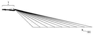
図3は、実施例1に係る光学系1を用いた画像投写装置の使用態様を示す説明図である。光学系1を含む画像投写装置は、テーブルなどの支持台の上に、または床の上に水平に配置される。スクリーンSCが、支持台から比較的短い水平距離、例えば、0.5mだけ離れた位置に、垂直上方に設置される。光学系1から発生した光は、前方斜め上方に向けて投写され、短焦点かつ大画面の投写を実現する。
FIG. 3 is an explanatory diagram showing how the image projection apparatus using the
図4は、実施例1に係る光学系1において反射面R1とY方向中間像IMyおよびX方向中間像IMxとの相対位置関係を示すグラフであり、Y断面に対して垂直な方向から見ている。横軸は、原画像SAのX方向中心を通り、Y方向最下部の光線が形成するIMxを基準としたZ方向の相対位置(単位mm)であり、縦軸は、原画像SAのX方向中心を通り、Y方向最下部の光線が形成するIMxを基準としたY方向の相対位置(単位mm)である。菱形マークは、X方向中間像IMxを示し、四角形マークは、Y方向中間像IMyを示し、三角形マークは、反射面R1の湾曲形状を示す。X方向中間像IMxは、光学系1を通過する光束がX方向にのみ集光し、Y方向には集光していない状態である。Y方向中間像IMyは、光学系1を通過する光束がY方向にのみ集光し、X方向には集光していない状態である。
FIG. 4 is a graph showing the relative positional relationship between the reflective surface R1 and the Y-direction intermediate image IMy and the X-direction intermediate image IMx in the
グラフを見ると、Y方向中間像IMyは、座標(-2.5,0)付近から座標(-19.5,-14.5)付近に向けてZ方向に対して斜めに分布している。X方向中間像IMxは、座標(0,0)付近から座標(-13,-15)付近に向けてZ方向に対して斜めに、かつ、縮小光路側に凹面を向けた形状で分布している。反射面R1は、座標(9,0)付近から座標(0.5,-17)付近に向けてZ方向に対して斜めに、かつ、縮小光路側に凹面を向けた形状で分布している。 Looking at the graph, the Y-direction intermediate image IMy is distributed obliquely to the Z direction from around the coordinates (-2.5, 0) to around the coordinates (-19.5, -14.5). . The X-direction intermediate image IMx is distributed obliquely to the Z direction from around the coordinates (0, 0) to around the coordinates (-13, -15), and in a shape with a concave surface facing the reduction optical path side. There is. The reflective surfaces R1 are distributed obliquely to the Z direction from around coordinates (9, 0) to around coordinates (0.5, -17), and have a concave surface facing the reduction optical path side. .
本開示では、反射面R1は、前記矩形領域の長手方向の中心を通る光線のX断面に平行なX方向の中間結像位置に沿って縮小光路側に凹面を向けた形状を有してもよい。これによりスクリーンSC上での画像歪みを抑制できる。 In the present disclosure, the reflective surface R1 may have a shape with a concave surface facing the reduction optical path side along an intermediate imaging position in the X direction parallel to the X cross section of the light ray passing through the center in the longitudinal direction of the rectangular region. good. This makes it possible to suppress image distortion on the screen SC.
(実施例2)
図5は、実施例2に係る光学系1を示す配置図である。この光学系1は、実施例1と同様な構成を有するが、第1サブ光学系は、レンズ素子L1~L13を含み、プリズムPMを含む第2サブ光学系は、画像投写装置の場合、前方斜め下方に向けて投写している。以下、実施例1と重複する説明は省略する。
(Example 2)
FIG. 5 is a layout diagram showing the
レンズ素子L1は、縮小側に凸面を向けた正メニスカス形状を有する(面4,5)。レンズ素子L2は、縮小側に凸面を向けた負メニスカス形状を有する(面6,7)。レンズ素子L3は、両凸形状を有する(面7,8)。レンズ素子L4は、拡大側に凸面を向けた負メニスカス形状を有する(面8,9)。レンズ素子L2~L4は、互いに接合されて複合レンズを構成する。レンズ素子L5は、両凹形状を有する(面10,11)。レンズ素子L6は、両凸形状を有する(面11,12)。レンズ素子L5,L6は、互いに接合されて複合レンズを構成する。 The lens element L1 has a positive meniscus shape with a convex surface facing the reduction side (surfaces 4 and 5). The lens element L2 has a negative meniscus shape with a convex surface facing the reduction side (surfaces 6, 7). Lens element L3 has a biconvex shape (surfaces 7, 8). The lens element L4 has a negative meniscus shape with a convex surface facing the magnification side (surfaces 8, 9). The lens elements L2 to L4 are joined together to form a compound lens. Lens element L5 has a biconcave shape (surfaces 10, 11). Lens element L6 has a biconvex shape (surfaces 11, 12). Lens elements L5 and L6 are cemented together to form a compound lens.
レンズ素子L7は、両凸形状を有する(面14,15)。レンズ素子L8は、拡大側に凸面を向けた負メニスカス形状を有する(面16,17)。レンズ素子L9は、両凸形状を有する(面18,19)。レンズ素子L10は、両凸形状を有する(面20,21)。レンズ素子L11は、両凹形状を有する(面21,22)。レンズ素子L10,L11は、互いに接合されて複合レンズを構成する。レンズ素子L12は、縮小側に凸面を向けた負メニスカス形状を有する(面23,24)。レンズ素子L13は、両凸形状を有する(面25,26)。 Lens element L7 has a biconvex shape (surfaces 14, 15). Lens element L8 has a negative meniscus shape with a convex surface facing the magnification side (surfaces 16, 17). Lens element L9 has a biconvex shape (surfaces 18, 19). Lens element L10 has a biconvex shape (surfaces 20, 21). Lens element L11 has a biconcave shape (surfaces 21, 22). Lens elements L10 and L11 are cemented together to form a compound lens. The lens element L12 has a negative meniscus shape with a convex surface facing the reduction side (surfaces 23, 24). Lens element L13 has a biconvex shape (surfaces 25, 26).
プリズムPMは、縮小側に位置する透過面Aと、拡大側に位置する透過面Bと、透過面Aと透過面Bとの間の光路上に位置する2つの反射面R1,R2を有する。透過面Aは、縮小側に凹面を向けた自由曲面形状を有する(面27)。反射面R1は、反射面R1へ入射する光線が反射する方向に凹面を向けた自由曲面形状を有する(面28)。反射面R2は、平面形状を有する(面29)。透過面Bは、拡大側に凸面を向けた自由曲面形状を有する(面30)。前記Y断面に対して垂直な方向からプリズムPMを見て、前記矩形領域の法線の方向を用いて表した場合、透過面Aは、プリズムPMから第1サブ光学系に向けた前記法線の第1方向のみを向いて配置され、透過面Bは、前記第1方向とは反対の第2方向のみを向いて配置される。前記Y断面に対して垂直な方向からプリズムPMを見た場合、透過面Aは、透過面Bとは異なる形状を有する。透過面Aおよび透過面Bは、互いに離間して配置される。 The prism PM has a transmission surface A located on the reduction side, a transmission surface B located on the enlargement side, and two reflection surfaces R1 and R2 located on the optical path between the transmission surface A and the transmission surface B. The transmission surface A has a free-form surface shape with a concave surface facing the reduction side (surface 27). The reflective surface R1 has a free-form surface shape with a concave surface facing in the direction in which the light beam incident on the reflective surface R1 is reflected (surface 28). The reflective surface R2 has a planar shape (surface 29). The transmission surface B has a free-form surface shape with a convex surface facing the magnification side (surface 30). When the prism PM is viewed from a direction perpendicular to the Y cross-section and expressed using the direction of the normal line of the rectangular area , the transmission surface A is the normal line from the prism PM toward the first sub-optical system. The transmitting surface B is arranged facing only in a first direction , and the transmission surface B is arranged facing only in a second direction opposite to the first direction . When the prism PM is viewed from a direction perpendicular to the Y cross section, the transmission surface A has a different shape from the transmission surface B. The transmission surface A and the transmission surface B are spaced apart from each other.
図6(a)は、実施例2に係る光学系1において主光線が通過する光路を示すY断面図であり、図6(b)は、光学系1を上方から見たときのX断面図である。
6(a) is a Y cross-sectional view showing the optical path through which the principal ray passes in the
図6(a)では、明確化のために、原画像SAのX方向の中心を通りY方向の最下部(縮小共役点での規格化高さY=0.0)を通過する主光線と、原画像SAのX方向の中心を通りY方向の最上部(縮小共役点での規格化高さY=1.0)を通過する主光線とを示す。両者の主光線は、第1サブ光学系を通過して、透過面Aを通ってプリズムPMの内部に入り、続いて反射面R1によって反射され、反射面R2に到達する手前で、破線円で示す領域CRyにおいて互いに交差している。 In FIG. 6(a), for clarity, the chief ray that passes through the center of the original image SA in the X direction and the lowest point in the Y direction (normalized height Y = 0.0 at the reduction conjugate point) , and the principal ray passing through the center of the original image SA in the X direction and the top in the Y direction (normalized height Y=1.0 at the reduction conjugate point). Both chief rays pass through the first sub-optical system, enter the interior of the prism PM through the transmission surface A, and are then reflected by the reflection surface R1, and before reaching the reflection surface R2, they are indicated by the broken line circle. They intersect with each other in the region CRy shown.
図6(b)では、明確化のために、原画像SAのX方向左端部を通過する主光線と、原画像SAのX方向右端部を通過する主光線とを示す。両者の主光線は、第1サブ光学系を通過して、透過面Aを通ってプリズムPMの内部に入り、続いて反射面R1によって反射され、反射面R2に到達する手前で、破線円で示す領域CRxにおいて互いに交差している。 In FIG. 6(b), for clarity, a chief ray passing through the left end of the original image SA in the X direction and a chief ray passing through the right end of the original image SA in the X direction are shown. Both chief rays pass through the first sub-optical system, enter the interior of the prism PM through the transmission surface A, and are then reflected by the reflection surface R1, and before reaching the reflection surface R2, they are indicated by the broken line circle. They intersect with each other in the region CRx shown.
図7は、実施例2に係る光学系1を用いた画像投写装置の使用態様を示す説明図である。光学系1を含む画像投写装置は、テーブルなどの支持台の上に、または床の上に水平に配置される。スクリーンSCが、支持台から比較的短い垂直距離、例えば、0.3mだけ離れた位置に水平前方に設置される。光学系1から発生した光は、前方斜め下方に向けて投写され、短焦点かつ大画面の投写を実現する。
FIG. 7 is an explanatory diagram showing how an image projection apparatus using the
図8は、実施例2に係る光学系1において反射面R1とY方向中間像IMyおよびX方向中間像IMxとの相対位置関係を示すグラフであり、Y断面に対して垂直な方向から見ている。
FIG. 8 is a graph showing the relative positional relationship between the reflective surface R1 and the Y-direction intermediate image IMy and the X-direction intermediate image IMx in the
グラフを見ると、Y方向中間像IMyは、座標(-3.5,0)付近から座標(-17,-10)付近に向けてZ方向に対して斜めに分布している。X方向中間像IMxは、座標(0,0)付近から座標(-12,-10)付近に向けてZ方向に対して斜めに、かつ、縮小光路側に凹面を向けた形状で分布している。反射面R1は、座標(5.5,0)付近から座標(-2,-11)付近に向けてZ方向に対して斜めに、かつ、縮小光路側に凹面を向けた形状で分布している。 Looking at the graph, the Y-direction intermediate image IMy is distributed obliquely with respect to the Z direction from around the coordinates (-3.5, 0) to around the coordinates (-17, -10). The X-direction intermediate image IMx is distributed obliquely to the Z direction from around coordinates (0, 0) to around coordinates (-12, -10), and in a shape with a concave surface facing the reduction optical path side. There is. The reflective surface R1 is distributed obliquely to the Z direction from around the coordinates (5.5, 0) to around the coordinates (-2, -11), and has a concave surface facing the reduction optical path side. There is.
本開示では、反射面R1は、前記矩形領域の長手方向の中心を通る光線のX断面に平行なX方向の中間結像位置に沿って縮小光路側に凹面を向けた形状を有してもよい。これによりスクリーンSC上での画像歪みを抑制できる。 In the present disclosure, the reflective surface R1 may have a shape with a concave surface facing the reduction optical path side along an intermediate imaging position in the X direction parallel to the X cross section of the light ray passing through the center in the longitudinal direction of the rectangular region. good. This makes it possible to suppress image distortion on the screen SC.
(実施例3)
図9は、実施例3に係る光学系1を示す配置図である。この光学系1は、実施例1と同様な構成を有するが、第1サブ光学系は、レンズ素子L1~L14を含み、プリズムPMを含む第2サブ光学系は、画像投写装置の場合、後方斜め上方に向けて投写している。以下、実施例1と重複する説明は省略する。
(Example 3)
FIG. 9 is a layout diagram showing the
レンズ素子L1は、縮小側に凸面を向けた正メニスカス形状を有する(面4,5)。レンズ素子L2は、縮小側に凸面を向けた負メニスカス形状を有する(面6,7)。レンズ素子L3は、両凸形状を有する(面7,8)。レンズ素子L4は、拡大側に凸面を向けた負メニスカス形状を有する(面8,9)。レンズ素子L2~L4は、互いに接合されて複合レンズを構成する。レンズ素子L5は、両凹形状を有する(面10,11)。レンズ素子L6は、両凸形状を有する(面11,12)。レンズ素子L5,L6は、互いに接合されて複合レンズを構成する。 The lens element L1 has a positive meniscus shape with a convex surface facing the reduction side (surfaces 4 and 5). The lens element L2 has a negative meniscus shape with a convex surface facing the reduction side (surfaces 6, 7). Lens element L3 has a biconvex shape (surfaces 7, 8). The lens element L4 has a negative meniscus shape with a convex surface facing the magnification side (surfaces 8, 9). The lens elements L2 to L4 are joined together to form a compound lens. Lens element L5 has a biconcave shape (surfaces 10, 11). Lens element L6 has a biconvex shape (surfaces 11, 12). Lens elements L5 and L6 are cemented together to form a compound lens.
レンズ素子L7は、両凸形状を有する(面14,15)。レンズ素子L8は、拡大側に凸面を向けた負メニスカス形状を有する(面16,17)。レンズ素子L9は、拡大側に凸面を向けた正メニスカス形状を有する(面17,18)。レンズ素子L8,L9は、互いに接合されて複合レンズを構成する。レンズ素子L10は、両凸形状を有する(面19,20)。レンズ素子L11は、両凸形状を有する(面21,22)。レンズ素子L12は、両凹形状を有する(面22,23)。レンズ素子L11,L12は、互いに接合されて複合レンズを構成する。レンズ素子L13は、縮小側に凸面を向けた負メニスカス形状を有する(面24,25)。レンズ素子L14は、拡大側に凸面を向けた正メニスカス形状を有する(面26,27)。 Lens element L7 has a biconvex shape (surfaces 14, 15). Lens element L8 has a negative meniscus shape with a convex surface facing the magnification side (surfaces 16, 17). Lens element L9 has a positive meniscus shape with a convex surface facing the magnification side (surfaces 17, 18). Lens elements L8 and L9 are joined together to form a compound lens. Lens element L10 has a biconvex shape (surfaces 19, 20). The lens element L11 has a biconvex shape (surfaces 21, 22). Lens element L12 has a biconcave shape (surfaces 22, 23). Lens elements L11 and L12 are cemented together to form a compound lens. The lens element L13 has a negative meniscus shape with a convex surface facing the reduction side (surfaces 24, 25). The lens element L14 has a positive meniscus shape with a convex surface facing the magnification side (surfaces 26, 27).
プリズムPMは、縮小側に位置する透過面Aと、拡大側に位置する透過面Bと、透過面Aと透過面Bとの間の光路上に位置する1つの反射面R1を有する。透過面Aは、縮小側に凹面を向けた自由曲面形状を有する(面28)。反射面R1は、反射面R1へ入射する光線が反射する方向に凹面を向けた自由曲面形状を有する(面29)。透過面Bは、拡大側に凸面を向けた自由曲面形状を有する(面30)。 Prism PM has a transmission surface A located on the reduction side, a transmission surface B located on the enlargement side, and one reflection surface R1 located on the optical path between transmission surface A and transmission surface B. The transmission surface A has a free-form surface shape with a concave surface facing the reduction side (surface 28). The reflective surface R1 has a free-form surface shape with a concave surface facing in the direction in which the light beam incident on the reflective surface R1 is reflected (surface 29). The transmission surface B has a free-form surface shape with a convex surface facing the magnification side (surface 30).
図10(a)は、実施例3に係る光学系1において主光線が通過する光路を示すY断面図であり、図10(b)は、光学系1を上方から見たときのそのX断面図である。
FIG. 10(a) is a Y cross-sectional view showing the optical path through which the principal ray passes in the
図10(a)では、明確化のために、原画像SAのX方向の中心を通りY方向の最下部(縮小共役点での規格化高さY=0.0)を通過する主光線と、原画像SAのX方向の中心を通りY方向の最上部(縮小共役点での規格化高さY=1.0)を通過する主光線とを示す。両者の主光線は、第1サブ光学系を通過して、透過面Aを通ってプリズムPMの内部に入り、続いて反射面R1によって反射され、透過面Bに到達する手前で、破線円で示す領域CRyにおいて互いに交差している。 In FIG. 10(a), for clarity, the chief ray passing through the center of the original image SA in the X direction and the lowest part in the Y direction (normalized height Y = 0.0 at the reduction conjugate point) , and the principal ray passing through the center of the original image SA in the X direction and the top in the Y direction (normalized height Y=1.0 at the reduction conjugate point). Both principal rays pass through the first sub-optical system, enter the interior of the prism PM through the transmission surface A, are then reflected by the reflection surface R1, and, before reaching the transmission surface B, are indicated by the broken line circle. They intersect with each other in the region CRy shown.
図10(b)では、明確化のために、原画像SAのX方向左端部を通過する主光線と、原画像SAのX方向右端部を通過する主光線とを示す。両者の主光線は、第1サブ光学系を通過して、透過面Aを通ってプリズムPMの内部に入り、続いて反射面R1によって反射され、透過面Bに到達する手前で、破線円で示す領域CRxにおいて互いに交差している。 In FIG. 10(b), for clarity, a chief ray passing through the left end of the original image SA in the X direction and a chief ray passing through the right end of the original image SA in the X direction are shown. Both principal rays pass through the first sub-optical system, enter the interior of the prism PM through the transmission surface A, are then reflected by the reflection surface R1, and, before reaching the transmission surface B, are indicated by the broken line circle. They intersect with each other in the region CRx shown.
図11は、実施例3に係る光学系1を用いた画像投写装置の使用態様を示す説明図である。光学系1を含む画像投写装置は、テーブルなどの支持台の上に、または床の上に水平に配置される。スクリーンSCが、支持台から後方側に比較的短い水平距離、例えば、0.6mだけ離れた位置に、垂直上方に設置される。光学系1から発生した光は、後方に斜め上方に向けて投写され、短焦点かつ大画面の投写を実現する。
FIG. 11 is an explanatory diagram showing how an image projection apparatus using the
図12は、実施例3に係る光学系1において反射面R1とY方向中間像IMyおよびX方向中間像IMxとの相対位置関係を示すグラフであり、Y断面に対して垂直な方向から見ている。
FIG. 12 is a graph showing the relative positional relationship between the reflective surface R1 and the Y-direction intermediate image IMy and the X-direction intermediate image IMx in the
グラフを見ると、Y方向中間像IMyは、座標(-2,0)付近から座標(-19,-14.5)付近に向けてZ方向に対して斜めに分布している。X方向中間像IMxは、座標(0,0)付近から座標(-12.5,-15)付近に向けてZ方向に対して斜めに、かつ、縮小光路側に凹面を向けた形状で分布している。反射面R1は、座標(9,0)付近から座標(1,-17)付近に向けてZ方向に対して斜めに、かつ、縮小光路側に凹面を向けた形状で分布している。 Looking at the graph, the Y-direction intermediate image IMy is distributed obliquely with respect to the Z direction from around the coordinates (-2, 0) to around the coordinates (-19, -14.5). The X-direction intermediate image IMx is distributed obliquely to the Z direction from around coordinates (0, 0) to around coordinates (-12.5, -15), with a concave surface facing the reduction optical path side. are doing. The reflective surfaces R1 are distributed obliquely to the Z direction from near the coordinates (9,0) to near the coordinates (1,-17), and have a concave surface facing the reduction optical path side.
本開示では、反射面R1は、前記矩形領域の長手方向の中心を通る光線のX断面に平行なX方向の中間結像位置に沿って縮小光路側に凹面を向けた形状を有してもよい。これによりスクリーンSC上での画像歪みを抑制できる。 In the present disclosure, the reflective surface R1 may have a shape with a concave surface facing the reduction optical path side along an intermediate imaging position in the X direction parallel to the X cross section of the light ray passing through the center in the longitudinal direction of the rectangular region. good. This makes it possible to suppress image distortion on the screen SC.
(実施例4)
図13は、実施例4に係る光学系1を示す配置図である。この光学系1は、実施例1と同様な構成を有するが、第1サブ光学系は、レンズ素子L1~L3およびプリズムPFを含み、プリズムPMを含む第2サブ光学系は、画像投写装置の場合、後方斜め上方に向けて投写している。以下、実施例1と重複する説明は省略する。
(Example 4)
FIG. 13 is a layout diagram showing the
レンズ素子L1は、両凸形状を有する(面2,3)。レンズ素子L2は、拡大側に凸面を向けた負メニスカス形状を有する(面4,5)。レンズ素子L3は、拡大側に凸面を向けた負メニスカス形状を有する(面6,7)。 Lens element L1 has a biconvex shape (surfaces 2, 3). The lens element L2 has a negative meniscus shape with a convex surface facing the magnification side (surfaces 4 and 5). The lens element L3 has a negative meniscus shape with a convex surface facing the magnification side (surfaces 6, 7).
プリズムPFは、プリズムPMと同様に、透明な媒質、例えば、ガラス、合成樹脂などで形成される。プリズムPFは、縮小側に位置する透過面Pと、拡大側に位置する透過面Qと、透過面Pと透過面Qとの間の光路上に位置する3つの反射面K1,K2,K3を有する。透過面Pは、縮小側に凹面を向けた自由曲面形状を有する(面9)。反射面K1は、縮小側および拡大側に凹面を向けた自由曲面形状を有する(面10)。反射面K2は、縮小側および拡大側に凸面を向けた自由曲面形状を有する(面11)。反射面K3は、縮小側および拡大側に凹面を向けた自由曲面形状を有する(面12)。透過面Qは、縮小側に凸面を向けた自由曲面形状を有する(面13)。 Prism PF, like prism PM, is formed of a transparent medium such as glass or synthetic resin. The prism PF has a transmission surface P located on the reduction side, a transmission surface Q located on the enlargement side, and three reflection surfaces K1, K2, K3 located on the optical path between the transmission surface P and the transmission surface Q. have The transmission surface P has a free-form surface shape with a concave surface facing the reduction side (surface 9). The reflective surface K1 has a free-form surface shape with concave surfaces facing the reduction side and the enlargement side (surface 10). The reflective surface K2 has a free-form surface shape with convex surfaces facing the reduction side and the enlargement side (surface 11). The reflective surface K3 has a free-form surface shape with concave surfaces facing the reduction side and the enlargement side (surface 12). The transmission surface Q has a free-form surface shape with a convex surface facing the reduction side (surface 13).
プリズムPMは、縮小側に位置する透過面Aと、拡大側に位置する透過面Bと、透過面Aと透過面Bとの間の光路上に位置する2つの反射面R1,R2を有する。透過面Aは、縮小側に凸面を向けた自由曲面形状を有する(面14)。反射面R1は、縮小側および拡大側に凹面を向けた自由曲面形状を有する(面15)。反射面R2は、反射面R2へ入射する光線が反射する方向に凸面を向けた自由曲面形状を有する(面16)。透過面Bは、拡大側に凸面を向けた自由曲面形状を有する(面17)。前記Y断面に対して垂直な方向からプリズムPMを見て、前記矩形領域の法線の方向を用いて表した場合、透過面Aは、プリズムPMから第1サブ光学系に向けた前記法線の第1方向のみを向いて配置され、透過面Bは、前記第1方向とは反対の第2方向のみを向いて配置される。前記Y断面に対して垂直な方向からプリズムPMを見た場合、透過面Aは、透過面Bとは異なる形状を有する。透過面Aおよび透過面Bは、互いに離間して配置される。反射面R2は、反射面R2へ入射する光線が反射する方向に凸面を向けた形状を有する。反射面R1,R2は、非平面の曲率を有する。 The prism PM has a transmission surface A located on the reduction side, a transmission surface B located on the enlargement side, and two reflection surfaces R1 and R2 located on the optical path between the transmission surface A and the transmission surface B. The transmission surface A has a free-form surface shape with a convex surface facing the reduction side (surface 14). The reflective surface R1 has a free-form surface shape with concave surfaces facing the reduction side and the enlargement side (surface 15). The reflective surface R2 has a free-form surface shape (surface 16) with a convex surface facing the direction in which the light rays incident on the reflective surface R2 are reflected. The transmission surface B has a free-form surface shape with a convex surface facing the enlargement side (surface 17). When the prism PM is viewed from a direction perpendicular to the Y cross-section and expressed using the direction of the normal line of the rectangular area , the transmission surface A is the normal line from the prism PM toward the first sub-optical system. The transmitting surface B is arranged facing only in a first direction , and the transmission surface B is arranged facing only in a second direction opposite to the first direction . When the prism PM is viewed from a direction perpendicular to the Y cross section, the transmission surface A has a different shape from the transmission surface B. The transmission surface A and the transmission surface B are spaced apart from each other. The reflective surface R2 has a shape with a convex surface facing the direction in which the light rays incident on the reflective surface R2 are reflected. The reflective surfaces R1 and R2 have non-planar curvature.
開口絞りSTは、光学系1を光束が通過する範囲を規定するものであり、縮小共役点と上述した中間結像位置との間に位置決めされる。一例として、開口絞りSTは、レンズ素子L3とプリズムPMの透過面Pとの間に位置する(面8)。
The aperture stop ST defines the range through which the light flux passes through the
図14(a)は、実施例4に係る光学系1において主光線が通過する光路を示すY断面図であり、図14(b)は、光学系1を上方から見たときのX断面図である。
14(a) is a Y cross-sectional view showing the optical path through which the principal ray passes in the
図14(a)では、明確化のために、原画像SAのX方向の中心を通りY方向の最下部(縮小共役点での規格化高さY=0.0)を通過する主光線と、原画像SAのX方向の中心を通りY方向の最上部(縮小共役点での規格化高さY=1.0)を通過する主光線とを示す。両者の主光線は、第1サブ光学系を通過して、透過面Aを通ってプリズムPMの内部に入り、続いて反射面R1によって反射され、反射面R2に到達する手前で、破線円で示す領域CRyにおいて互いに交差している。 In FIG. 14(a), for clarity, the chief ray passing through the center of the original image SA in the X direction and the lowest point in the Y direction (normalized height Y = 0.0 at the reduction conjugate point) , and the principal ray passing through the center of the original image SA in the X direction and the top in the Y direction (normalized height Y=1.0 at the reduction conjugate point). Both chief rays pass through the first sub-optical system, enter the interior of the prism PM through the transmission surface A, and are then reflected by the reflection surface R1, and before reaching the reflection surface R2, they are indicated by the broken line circle. They intersect with each other in the region CRy shown.
図14(b)では、明確化のために、原画像SAのX方向左端部を通過する主光線と、原画像SAのX方向右端部を通過する主光線とを示す。両者の主光線は、第1サブ光学系を通過して、透過面Aを通ってプリズムPMの内部に入り、続いて反射面R1によって反射され、反射面R2に到達する手前で、破線円で示す領域CRxにおいて互いに交差している。 In FIG. 14(b), for clarity, a chief ray passing through the left end of the original image SA in the X direction and a chief ray passing through the right end of the original image SA in the X direction are shown. Both chief rays pass through the first sub-optical system, enter the interior of the prism PM through the transmission surface A, and are then reflected by the reflection surface R1, and before reaching the reflection surface R2, they are indicated by the broken line circle. They intersect with each other in the region CRx shown.
図15は、実施例4に係る光学系1を用いた画像投写装置の使用態様を示す説明図である。光学系1を含む画像投写装置は、テーブルなどの支持台の上に、または床の上に水平に配置される。スクリーンSCが、支持台から後方側に比較的短い水平距離、例えば、0.2mだけ離れた位置に、垂直上方に設置される。光学系1から発生した光は、後方斜め上方に向けて投写され、短焦点かつ大画面の投写を実現する。
FIG. 15 is an explanatory diagram showing how an image projection apparatus using the
図16は、実施例4に係る光学系1において反射面R1とY方向中間像IMyおよびX方向中間像IMxとの相対位置関係を示すグラフであり、Y断面に対して垂直な方向から見ている。
FIG. 16 is a graph showing the relative positional relationship between the reflective surface R1 and the Y-direction intermediate image IMy and the X-direction intermediate image IMx in the
グラフを見ると、Y方向中間像IMyは、座標(-1,0)付近から座標(12,-5.7)付近に向けてZ方向に対して斜めに分布している。X方向中間像IMxは、座標(0,0)付近から座標(7.5,-6)付近に向けてZ方向に対して斜めに、かつ、縮小光路側に凹面を向けた形状で分布している。反射面R1は、座標(-4.5,-0.5)付近から座標(-0.8,-6.8)付近に向けてZ方向に対して斜めに、かつ、縮小光路側に凹面を向けた形状で分布している。 Looking at the graph, the Y-direction intermediate image IMy is distributed obliquely with respect to the Z direction from around the coordinates (-1, 0) to around the coordinates (12, -5.7). The X-direction intermediate image IMx is distributed obliquely to the Z direction from around the coordinates (0, 0) to around the coordinates (7.5, -6), and in a shape with a concave surface facing the reduction optical path side. ing. The reflective surface R1 is oblique to the Z direction from around the coordinates (-4.5, -0.5) to around the coordinates (-0.8, -6.8), and is concave toward the reduced optical path side. It is distributed in a shape that points toward the
本開示では、反射面R1は、前記矩形領域の長手方向の中心を通る光線のX断面に平行なX方向の中間結像位置に沿って縮小光路側に凹面を向けた形状を有してもよい。これによりスクリーンSC上での画像歪みを抑制できる。実施例4に係る光学系1において、プリズムPFとプリズムPMは、異なる屈折率、アッベ数を有する媒質で構成される方が、同じ媒質で構成する場合と比べて倍率色収差補正により効果的である。
In the present disclosure, the reflective surface R1 may have a shape with a concave surface facing the reduction optical path side along an intermediate imaging position in the X direction parallel to the X cross section of the light ray passing through the center in the longitudinal direction of the rectangular region. good. This makes it possible to suppress image distortion on the screen SC. In the
次に、本実施形態に係る光学系が満足し得る条件を説明する。なお、各実施例に係る光学系に対して、複数の条件が規定されるが、これら複数の条件すべてを満足してもよく、あるいは個別の条件を満足することにより、それぞれ対応する効果が得られる。 Next, conditions that can be satisfied by the optical system according to this embodiment will be explained. Although a plurality of conditions are specified for the optical system according to each example, it is possible to satisfy all of these conditions, or to obtain the corresponding effect by satisfying individual conditions. It will be done.
本実施形態に係る光学系は、縮小側の縮小共役点および拡大側の拡大共役点を有し、該縮小共役点および該拡大共役点とそれぞれ共役である中間結像位置を内部に有する光学系1であって、
前記縮小共役点は、長手方向及び短手方向を有する矩形領域において結像関係を有し、
前記光学系1を光束が通過する範囲を規定する開口絞りSTを含む第1サブ光学系と、
該第1サブ光学系より拡大側に設けられ、透明な媒質で形成されたプリズムPMを含む第2サブ光学系とを備え、
前記プリズムPMは、縮小側に位置する透過面A、拡大側に位置する透過面B、および該透過面Aと該透過面Bとの間の光路上に位置する少なくとも1つの反射面R1を有し、
前記開口絞りSTは、前記縮小共役点と前記中間結像位置との間に位置決めされ、
前記中間結像位置に形成される中間像IMx,IMyの一部または全部が、前記プリズムPMの媒質内部に位置決めされ、
前記中間結像位置に最も近接した反射面R1は、前記反射面R1へ入射する光線が反射する方向に凹面を向けた形状を有し、
前記透過面Bは、拡大側に凸面を向けた形状を有し、
前記縮小共役点の前記矩形領域の長手方向をX方向、短手方向をY方向、法線方向をZ方向としたとき、X方向の中心を通る主光線が前記反射面R1で反射する位置を含む面をY断面とし、該Y断面に対して垂直な断面をX断面として、Y断面に対して垂直な方向から見たとき、前記縮小共役点を通過する複数の主光線の一部が前記反射面R1と前記透過面Bとの間の光路上で交差するように、かつ、X断面に対して垂直な方向から見たとき、前記縮小共役点を通過する複数の主光線の一部が前記反射面R1と前記透過面Bとの間の光路上で交差するように、前記反射面R1の曲率形状が設定されてもよい。
The optical system according to the present embodiment has a reduction conjugate point on the reduction side and an enlargement conjugate point on the enlargement side, and has an intermediate imaging position therein that is conjugate with the reduction conjugate point and the enlargement conjugate point, respectively. 1,
The reduction conjugate point has an imaging relationship in a rectangular area having a longitudinal direction and a transverse direction,
a first sub-optical system including an aperture stop ST that defines a range through which the light flux passes through the
a second sub-optical system that is provided on the magnification side of the first sub-optical system and includes a prism PM formed of a transparent medium;
The prism PM has a transmission surface A located on the reduction side, a transmission surface B located on the expansion side, and at least one reflection surface R1 located on the optical path between the transmission surface A and the transmission surface B. death,
The aperture stop ST is positioned between the reduction conjugate point and the intermediate imaging position,
Part or all of the intermediate images IMx, IMy formed at the intermediate imaging position are positioned inside the medium of the prism PM,
The reflective surface R1 closest to the intermediate imaging position has a shape with a concave surface facing in the direction in which the light rays incident on the reflective surface R1 are reflected,
The transmission surface B has a shape with a convex surface facing the enlargement side,
When the longitudinal direction of the rectangular region of the reduction conjugate point is the X direction, the transversal direction is the Y direction, and the normal direction is the Z direction, the position where the chief ray passing through the center in the X direction is reflected on the reflective surface R1 is When viewed from a direction perpendicular to the Y cross section, with the plane including the Y cross section being the Y cross section and the cross section perpendicular to the Y cross section being the X cross section, some of the plurality of chief rays passing through the reduction conjugate point are When viewed from a direction perpendicular to the X-section and intersecting on the optical path between the reflective surface R1 and the transmitting surface B, some of the plurality of chief rays passing through the reduction conjugate point are The curvature shape of the reflective surface R1 may be set so that the reflective surface R1 and the transmitting surface B intersect on the optical path.
こうした構成によると、Y断面およびX断面の両方に関して、複数の主光線がプリズムの反射面R1と透過面Bとの間の光路上で交差している。そのため小型のプリズムを用いて、第2サブ光学系を小型化し、かつ、短焦点かつ大画面の投写または撮像が可能になる。 According to this configuration, a plurality of chief rays intersect on the optical path between the reflective surface R1 and the transmitting surface B of the prism in both the Y cross section and the X cross section. Therefore, by using a small prism, the second sub-optical system can be downsized, and it is possible to project or image a large screen with a short focus.
本実施形態に係る光学系は、前記反射面R1は、前記矩形領域の長手方向の中心を通る光線のX断面に平行なX方向の中間結像位置に沿って縮小光路側に凹面を向けた形状を有してもよい。 In the optical system according to the present embodiment, the reflective surface R1 has a concave surface facing the reduction optical path side along an intermediate imaging position in the X direction parallel to the X cross section of the light ray passing through the longitudinal center of the rectangular region. It may have a shape.
こうした構成によると、スクリーンSC上での画像歪みを抑制できる。 According to such a configuration, image distortion on the screen SC can be suppressed.
本実施形態に係る光学系では、前記第1サブ光学系を通過する光束は、Y断面とX断面とで異なる中間結像位置を含んでもよい。 In the optical system according to this embodiment, the light beam passing through the first sub-optical system may include different intermediate imaging positions in the Y cross section and the X cross section.
こうした構成によると、結像倍率をX方向とY方向とで個別に設定でき、設計の自由度が高くなる。 According to this configuration, the imaging magnification can be set individually in the X direction and the Y direction, increasing the degree of freedom in design.
図19は、中間結像位置における結像倍率MX,MYおよび拡大共役点における結像倍率MMX,MMYの定義を示す説明図である。本開示に係る光学系1において、縮小共役点、中間結像位置および拡大共役点は、互いに光学的に共役関係にある。
FIG. 19 is an explanatory diagram showing definitions of the imaging magnifications MX, MY at the intermediate imaging position and the imaging magnifications MMX, MMY at the expansion conjugate point. In the
Y方向に関して、縮小共役点での長さΔY1、Y方向の中間結像位置での長さΔY2、および拡大共役点での長さΔY3は、予め定めた倍率でそれぞれ結像される。この場合、縮小共役点に対するY断面に平行なY方向の中間結像位置における結像倍率MY、および縮小共役点に対する拡大共役点におけるY方向結像倍率MMYは、下記の式で与えられる。
MY=|ΔY2/ΔY1|
MMY=|ΔY3/ΔY1|
Regarding the Y direction, a length ΔY1 at the reduction conjugate point, a length ΔY2 at the intermediate imaging position in the Y direction, and a length ΔY3 at the enlargement conjugate point are imaged at predetermined magnifications, respectively. In this case, the imaging magnification MY at an intermediate imaging position in the Y direction parallel to the Y cross section with respect to the reduction conjugate point, and the Y direction imaging magnification MMY at the enlargement conjugate point with respect to the reduction conjugate point are given by the following formula.
MY=|ΔY2/ΔY1|
MMY=|ΔY3/ΔY1|
X方向に関しても同様に、縮小共役点での長さΔX1、X方向の中間結像位置での長さΔX2、および拡大共役点での長さΔX3は、予め定めた倍率でそれぞれ結像される。この場合、縮小共役点に対するX断面に平行なX方向の中間結像位置における結像倍率MX、および縮小共役点に対する拡大共役点におけるX方向結像倍率MMXは、下記の式で与えられる。
MX=|ΔX2/ΔX1|
MMX=|ΔX3/ΔX1|
Similarly, regarding the X direction, the length ΔX1 at the reduction conjugate point, the length ΔX2 at the intermediate imaging position in the X direction, and the length ΔX3 at the enlargement conjugate point are each imaged at a predetermined magnification. . In this case, the imaging magnification MX at an intermediate imaging position in the X direction parallel to the X cross section with respect to the reduction conjugate point, and the X direction imaging magnification MMX at the enlargement conjugate point with respect to the reduction conjugate point are given by the following formula.
MX=|ΔX2/ΔX1|
MMX=|ΔX3/ΔX1|
本実施形態に係る光学系は、以下の条件(1a)または条件(1b)を満足してもよい。
0<|MX|<10 ・・・(1a)
0<|MY|<10 ・・・(1b)
ここで、
MX:縮小共役点に対するX断面に平行なX方向の中間結像位置における結像倍率
MY:縮小共役点に対するY断面に平行なY方向の中間結像位置における結像倍率
である。
The optical system according to this embodiment may satisfy the following condition (1a) or condition (1b).
0<|MX|<10...(1a)
0<|MY|<10...(1b)
here,
MX: Imaging magnification at an intermediate imaging position in the X direction parallel to the X cross section with respect to the reduction conjugate point. MY: Imaging magnification at an intermediate imaging position in the Y direction parallel to the Y cross section with respect to the reduction conjugate point.
こうした構成によると、中間結像位置を適切に設定でき、第2サブ光学系を小型に維持しながら、スクリーンSC上での画像歪みを抑制できる。さらに、上記範囲においては、スクリーンSC上の、X方向結像倍率とY方向結像倍率の差を極力小さくできる。条件(1a)または条件(1b)の上限を超えると、第2サブ光学系内に形成する中間結像が大きくなり、小型化を維持することが困難となる。なお、中間結像位置における結像倍率MX、MYは縮小共役点での規格化高さY=0からY=1に向けて徐々に小さくなるように設定することが望ましい。そうすることで、中間結像位置の像面湾曲をアンダー側(縮小光路側)に設定でき、スクリーンSC上の像面湾曲を良好な範囲に抑えることが可能となる。 According to such a configuration, it is possible to appropriately set the intermediate imaging position, and it is possible to suppress image distortion on the screen SC while keeping the second sub-optical system small. Furthermore, within the above range, the difference between the X-direction imaging magnification and the Y-direction imaging magnification on the screen SC can be made as small as possible. If the upper limit of condition (1a) or condition (1b) is exceeded, the intermediate image formed within the second sub-optical system becomes large, making it difficult to maintain miniaturization. Note that it is desirable that the imaging magnifications MX and MY at the intermediate imaging position are set to gradually decrease from the normalized height Y=0 at the reduction conjugate point toward Y=1. By doing so, the curvature of field at the intermediate imaging position can be set to the underside (on the side of the reduced optical path), and the curvature of field on the screen SC can be suppressed within a favorable range.
さらに、以下の条件(1c)または(1d)を満足することで、上記効果をより奏功することができる。
0.5<|MX|<7.5 ・・・(1c)
0.5<|MY|<7.5 ・・・(1d)
Furthermore, by satisfying the following condition (1c) or (1d), the above effects can be more effectively achieved.
0.5<|MX|<7.5...(1c)
0.5<|MY|<7.5...(1d)
さらに、以下の条件(1e)または(1f)を満足することで、上記効果をより奏功することができる。
0.6<|MX|<5.0 ・・・(1e)
0.6<|MY|<5.0 ・・・(1f)
Furthermore, by satisfying the following condition (1e) or (1f), the above effects can be more effectively achieved.
0.6<|MX|<5.0...(1e)
0.6<|MY|<5.0...(1f)
本実施形態に係る光学系は、以下の条件(2)を満足してもよい。
|MX|>|MY| ・・・(2)
ここで、
MX:前記X方向結像倍率
MY:前記Y方向結像倍率
である。
The optical system according to this embodiment may satisfy the following condition (2).
|MX|>|MY| ...(2)
here,
MX: the imaging magnification in the X direction; MY: the imaging magnification in the Y direction.
こうした構成によると、スクリーンSC上のX方向結像倍率とY方向結像倍率の差を極力小さくできる。条件(2)を満たさない場合、スクリーンSC上にてX方向結像倍率とY方向結像倍率に差が生じ、適切な光学性能を維持することが困難となる。 With this configuration, the difference between the X-direction imaging magnification and the Y-direction imaging magnification on the screen SC can be minimized. If condition (2) is not satisfied, there will be a difference between the X-direction imaging magnification and the Y-direction imaging magnification on the screen SC, making it difficult to maintain appropriate optical performance.
本実施形態に係る光学系は、前記Y方向の中間結像位置と前記反射面R1との間に前記X方向の中間結像位置が存在してもよい。 In the optical system according to this embodiment, the intermediate imaging position in the X direction may exist between the intermediate imaging position in the Y direction and the reflective surface R1.
こうした構成によると、スクリーンSC上のX方向結像倍率とY方向結像倍率の差を極力小さくできる。 With this configuration, the difference between the X-direction imaging magnification and the Y-direction imaging magnification on the screen SC can be minimized.
本実施形態に係る光学系は、以下の条件(3)を満足してもよい。
Σ(|OPLY|-|OPLX|)>0 ・・・(3)
ここで、
OPLX:前記X方向の中間結像位置と前記反射面R1との間の光路長
OPLY:前記Y方向の中間結像位置と前記反射面R1との間の光路長
Σ(|OPLY|-|OPLX|):縮小共役点での規格化高さY=0.0,0.5,1.0をそれぞれ通過する3つの主光線について、光路長OPLXの絶対値と光路長OPLYの絶対値との差を加算した合計値
である。
The optical system according to this embodiment may satisfy the following condition (3).
Σ(|OPLY|-|OPLX|)>0...(3)
here,
OPLX: Optical path length between the intermediate imaging position in the X direction and the reflective surface R1 OPLY: Optical path length between the intermediate imaging position in the Y direction and the reflective surface R1 Σ(|OPLY|-|OPLX |): The absolute value of the optical path length OPLX and the absolute value of the optical path length OPLY for the three principal rays passing through the normalized heights Y=0.0, 0.5, and 1.0 at the reduced conjugate point, respectively. This is the total value obtained by adding the differences.
こうした構成によると、スクリーンSC上のX方向結像倍率とY方向結像倍率の差を極力小さくできる。条件(3)の下限値を下回る場合、スクリーンSC上のX方向結像倍率に対してY方向結像倍率が小さくなり、原画像SAを適切に再現することが困難となる。 With this configuration, the difference between the X-direction imaging magnification and the Y-direction imaging magnification on the screen SC can be minimized. If the lower limit of condition (3) is not reached, the Y-direction imaging magnification becomes smaller than the X-direction imaging magnification on the screen SC, making it difficult to properly reproduce the original image SA.
さらに、以下の条件(3a)を満足することで、上記効果をより奏功することができる。
Σ(|OPLY|-|OPLX|)>2.5 ・・・(3a)
Furthermore, by satisfying the following condition (3a), the above effects can be more achieved.
Σ(|OPLY|-|OPLX|)>2.5...(3a)
さらに、以下の条件(3b)を満足することで、上記効果をより奏功することができる。
Σ(|OPLY|-|OPLX|)>5.0 ・・・(3b)
Furthermore, by satisfying the following condition (3b), the above effects can be more effectively achieved.
Σ(|OPLY|-|OPLX|)>5.0...(3b)
本実施形態に係る光学系は、以下の条件(4)を満足してもよい。
|2×(MMX-MMY)/(MMX+MMY)|<0.30 ・・・(4)
ここで、
MMX:縮小共役点に対する拡大共役点におけるX方向結像倍率
MMY:縮小共役点に対する拡大共役点におけるY方向結像倍率
である。
The optical system according to this embodiment may satisfy the following condition (4).
|2×(MMX-MMY)/(MMX+MMY)|<0.30...(4)
here,
MMX: X-direction imaging magnification at the enlarged conjugate point relative to the reduced conjugate point MMY: Y-direction imaging magnification at the enlarged conjugate point relative to the reduced conjugate point.
こうした構成によると、スクリーンSC上での画像歪みを抑制でき、X方向結像倍率とY方向結像倍率の差を極力小さくできる。条件(4)の上限値を超える場合、スクリーンSC上のX方向結像倍率に対してY方向結像倍率が異なり、原画像SAを適切に再現することが困難となる。条件(4)はスクリーンSC上で原画像SAを適切に再現する範囲を規定している。 With this configuration, image distortion on the screen SC can be suppressed, and the difference between the X-direction imaging magnification and the Y-direction imaging magnification can be minimized. If the upper limit of condition (4) is exceeded, the Y-direction imaging magnification differs from the X-direction imaging magnification on the screen SC, making it difficult to properly reproduce the original image SA. Condition (4) defines the range in which the original image SA is appropriately reproduced on the screen SC.
さらに、以下の条件(4a)を満足することで、上記効果をより奏功することができる。
|2×(MMX-MMY)/(MMX+MMY)|<0.15 ・・・(4a)
Furthermore, by satisfying the following condition (4a), the above effects can be more achieved.
|2×(MMX-MMY)/(MMX+MMY)|<0.15...(4a)
さらに、以下の条件(4b)を満足することで、上記効果をより奏功することができる。
|2×(MMX-MMY)/(MMX+MMY)|<0.08 ・・・(4b)
Furthermore, by satisfying the following condition (4b), the above effects can be more achieved.
|2×(MMX-MMY)/(MMX+MMY)|<0.08...(4b)
本実施形態に係る光学系は、以下の条件(5)を満足してもよい。
|θi|<50 ・・・(5)
ここで、
θi:主光線が媒質の前記透過面Bを通過するときの前記透過面Bに主光線が入射する位置における前記透過面Bの法線に対する入射角(度)
である。
The optical system according to this embodiment may satisfy the following condition (5).
|θi|<50...(5)
here,
θi: Incident angle (degree) with respect to the normal to the transmission surface B at the position where the principal ray is incident on the transmission surface B when the principal ray passes through the transmission surface B of the medium
It is.
こうした構成によると、透過面Bを通過するときの透過面Bによる反射光を抑えることができ、透過光の損失を低減できるため、投写画像の光量低下を抑制できる。 According to such a configuration, it is possible to suppress the light reflected by the transmitting surface B when passing through the transmitting surface B, and the loss of transmitted light can be reduced, so that it is possible to suppress a decrease in the light amount of the projected image.
本実施形態に係る光学系は、前記透過面A、前記透過面Bおよび前記少なくとも1つの反射面R1のうち、前記透過面Bが最大の有効面積を有してもよい。 In the optical system according to this embodiment, the transmission surface B may have the largest effective area among the transmission surface A, the transmission surface B, and the at least one reflective surface R1.
こうした構成によると、投写画像において均一な光量を実現できる。 According to this configuration, a uniform amount of light can be achieved in the projected image.
本実施形態に係る光学系は、前記開口絞りSTは、前記縮小共役点と前記透過面Aとの間に位置決めしてもよい。 In the optical system according to this embodiment, the aperture stop ST may be positioned between the reduction conjugate point and the transmission surface A.
こうした構成によると、プリズムPMの小型化が図られる。 With this configuration, the prism PM can be made smaller.
本実施形態に係る光学系は、前記縮小共役点を通過する複数の主光線の全てが、前記反射面R1と前記透過面Bとの間の光路上で交差してもよい。 In the optical system according to the present embodiment, all of the plurality of principal rays passing through the reduction conjugate point may intersect on the optical path between the reflection surface R1 and the transmission surface B.
こうした構成によると、小型のプリズムを用いて、第2サブ光学系を小型化し、かつ、短焦点かつ大画面の投写または撮像が可能になる。 According to this configuration, the second sub-optical system can be downsized by using a small prism, and it is possible to project or image a large screen with a short focus.
本実施形態に係る光学系は、前記開口絞りに対応する入射瞳および射出瞳のいずれか一方が、前記プリズム内に位置決めされてもよい。なお、入射瞳は、縮小側から見た開口絞りの像である。射出瞳は、拡大側から見た開口絞りの像である。 In the optical system according to this embodiment, either an entrance pupil or an exit pupil corresponding to the aperture stop may be positioned within the prism. Note that the entrance pupil is an image of the aperture stop viewed from the reduction side. The exit pupil is an image of the aperture stop viewed from the magnifying side.
こうした構成によると、小型のプリズムを用いて、第2サブ光学系を小型化し、かつ、短焦点かつ大画面の投写または撮像が可能になる。 According to this configuration, the second sub-optical system can be downsized by using a small prism, and it is possible to project or image a large screen with a short focus.
本実施形態に係る光学系は、前記中間結像位置は、前記反射面R1から縮小側に離間して位置決めされてもよい。 In the optical system according to this embodiment, the intermediate imaging position may be positioned away from the reflective surface R1 toward the reduction side.
こうした構成によると、スクリーンSC上での画像歪みを抑制できる。 According to such a configuration, image distortion on the screen SC can be suppressed.
図20(a)~(d)は、プリズムPMの段付き構造の各種例を示すY方向断面図である。光学系1を構成する各種レンズ素子および各種プリズムは、一般に、接着剤、金具などを用いて鏡筒50の内部に取り付けられる。その際、光学設計の各種寸法を忠実に再現するために、高い精度の取り付け構造が必要になる。
FIGS. 20A to 20D are cross-sectional views in the Y direction showing various examples of stepped structures of the prism PM. Various lens elements and various prisms that constitute the
プリズムPMには、例えば、取り付け基準となる端面PMaおよび入隅部PMbが設けられる。一方、鏡筒50には、端面PMaおよび入隅部PMbの形状に対応した端面50aおよび出隅部50bが設けられる。取り付けの際、端面PMaと端面50aとが適合し、入隅部PMbと出隅部50bとが適合することによって、プリズムPMは、鏡筒50に対して高精度かつ安定に固定できる。
The prism PM is provided with, for example, an end face PMa and an inner corner part PMb that serve as attachment references. On the other hand, the
本実施形態に係る光学系は、前記プリズムPMの外周部に段付き構造が形成されてもよい。 In the optical system according to this embodiment, a stepped structure may be formed on the outer peripheral portion of the prism PM.
こうした構成によると、プリズムを外部ハウジングに対して高精度かつ安定に取り付け可能になる。 With this configuration, the prism can be attached to the external housing with high precision and stability.
本実施形態に係る光学系は、前記光学系は、結像光学系でもよい。 In the optical system according to this embodiment, the optical system may be an imaging optical system.
こうした構成によると、第2サブ光学系を小型化、かつ、短焦点かつ大画面の投写または撮像が可能になる。 According to such a configuration, the second sub-optical system can be miniaturized, and a short focus and large screen can be projected or imaged.
以下、実施例1~4に係る光学系の数値実施例を説明する。なお、各数値実施例において、表中の長さの単位はすべて「mm」であり、画角の単位はすべて「°」である。また、各数値実施例において、曲率半径、面間隔、Nd(d線に対する屈折率)、vd(d線に対するアッベ数)、N550(波長550nmでの屈折率)、偏心データ(光学系の一つ前の面に対するプリズム面の変位量X,Y,Zおよび一つ前の面に対するプリズム面の法線方向α,β,γ)を示す。また、面間隔において「可変」とあるのは、下側の表に示すように、拡大共役点での画像サイズ(100”(インチ),80”,60”など)に応じて変化可能であることを意味する。また、各数値実施例において、非球面の形状は次式で定義される。なお、非球面係数は、コーニック係数k以外は0でない係数のみ記す。 Numerical examples of the optical systems according to Examples 1 to 4 will be described below. In addition, in each numerical example, the unit of length in the table is all "mm", and the unit of angle of view is all "°". In addition, in each numerical example, the radius of curvature, interplanar spacing, Nd (refractive index for the d-line), vd (Abbe number for the d-line), N550 (refractive index at a wavelength of 550 nm), eccentricity data (one of the optical system The displacement amounts X, Y, Z of the prism surface relative to the previous surface and the normal directions α, β, γ) of the prism surface relative to the previous surface are shown. Also, "variable" in terms of surface spacing means that it can be changed depending on the image size (100" (inch), 80", 60", etc.) at the enlarged conjugate point, as shown in the table below. In addition, in each numerical example, the shape of the aspherical surface is defined by the following equation. Note that, as for the aspherical coefficients, only the coefficients other than the conic coefficient k that are not 0 are described.

ここで、
z:z軸に平行な面のサグ量、
r:半径方向の距離(=√(x2+y2))、
c:面頂点における曲率
k:コーニック係数、
A~H:rの4次~18次係数
である。
here,
z: Sag amount on the plane parallel to the z-axis,
r: radial distance (=√(x 2 + y 2 )),
c: curvature at surface apex k: conic coefficient,
A to H: 4th to 18th coefficients of r.
また、自由曲面形状は、その面頂点を原点とするローカルな直交座標系(x,y,z)
を用いた次式で定義している。
In addition, a free-form surface shape has a local orthogonal coordinate system (x, y, z) whose origin is the surface vertex.
It is defined using the following equation.


z:z軸に平行な面のサグ量
r:半径方向の距離(=√(x2+y2))
c:面頂点における曲率
k:コーニック係数
Cj:単項式xmynの係数
である。
z: Sag amount on the plane parallel to the z-axis r: Distance in the radial direction (=√(x 2 + y 2 ))
c: Curvature at the surface vertex k: Conic coefficient C j : Coefficient of monomial x m y n .
なお、以下の各データにおいて、多項式における自由曲面係数であるxのi次の項、yのj次の項を、x**i*y**jというように記載している。例えば、「X**2*Y」とは、多項式におけるxの2次、yの1次の項の自由曲面係数であることを示す。 In each data below, the i-th term of x and the j-th term of y, which are free-form surface coefficients in a polynomial, are written as x**i*y**j. For example, "X**2*Y" indicates the free-form surface coefficient of the second-order term of x and the first-order term of y in a polynomial.
(数値実施例1)
数値実施例1(実施例1に対応)の光学系について、レンズデータを表1に示し、レンズの非球面形状データを表2に示し、プリズムの自由曲面形状データを表3に示す。
(Numerical Example 1)
Regarding the optical system of Numerical Example 1 (corresponding to Example 1), lens data is shown in Table 1, aspherical surface shape data of the lens is shown in Table 2, and free-form surface shape data of the prism is shown in Table 3.


(数値実施例2)
数値実施例2(実施例2に対応)の光学系について、レンズデータを表4に示し、レンズの非球面形状データを表5に示し、プリズムの自由曲面形状データを表6に示す。
(Numerical Example 2)
Regarding the optical system of Numerical Example 2 (corresponding to Example 2), lens data is shown in Table 4, aspherical surface shape data of the lens is shown in Table 5, and free-form surface shape data of the prism is shown in Table 6.


(数値実施例3)
数値実施例3(実施例3に対応)の光学系について、レンズデータを表7に示し、レンズの非球面形状データを表8に示し、プリズムの自由曲面形状データを表9に示す。
(Numerical Example 3)
Regarding the optical system of Numerical Example 3 (corresponding to Example 3), lens data is shown in Table 7, aspherical surface shape data of the lens is shown in Table 8, and free-form surface shape data of the prism is shown in Table 9.


(数値実施例4)
数値実施例4(実施例4に対応)の光学系について、レンズデータを表10に示し、プリズムの自由曲面形状データを表11に示す。実施例4のみ、レンズデータは第1面基準の絶対値座標となる。
(Numerical Example 4)
Regarding the optical system of Numerical Example 4 (corresponding to Example 4), lens data is shown in Table 10, and free-form surface shape data of the prism is shown in Table 11. Only in Example 4, the lens data is absolute value coordinates based on the first surface.


以下の表12~表15に、各数値実施例1~4における各条件式(1)~(4)の対応値をそれぞれ示す。 Tables 12 to 15 below show the corresponding values of each conditional expression (1) to (4) in each numerical example 1 to 4, respectively.


以下の表16に、各数値実施例1~4における条件式(5)の対応値をそれぞれ示す。 Table 16 below shows the corresponding values of conditional expression (5) in each of Numerical Examples 1 to 4.

(実施形態2)
以下、図21を用いて本開示の実施形態2を説明する。図21は、本開示に係る画像投写装置の一例を示すブロック図である。画像投写装置100は、実施形態1で開示した光学系1と、画像形成素子101と、光源102と、制御部110などを備える。画像形成素子101は、液晶、DMDなどで構成され、光学系1を経由してスクリーンSCに投写する画像を生成する。光源102は、LED(発光ダイオード)、レーザなどで構成され、画像形成素子101に光を供給する。制御部110は、CPUまたはMPUなどで構成され、装置全体および各コンポーネントを制御する。光学系1は、画像投写装置100に対して着脱自在に取付け可能な交換レンズとして構成してもよく、あるいは画像投写装置100に一体化した組み込みレンズとして構成してもよい。
(Embodiment 2)
Embodiment 2 of the present disclosure will be described below using FIG. 21. FIG. 21 is a block diagram illustrating an example of an image projection device according to the present disclosure. The
以上の画像投写装置100は、実施形態1に係る光学系1により、小型な装置で短焦点かつ大画面の投写が可能になる。
The
(実施形態3)
以下、図22を用いて本開示の実施形態3を説明する。図22は、本開示に係る撮像装置の一例を示すブロック図である。撮像装置200は、実施形態1で開示した光学系1と、撮像素子201と、制御部210などを備える。撮像素子201は、CCD(電荷結合素子)イメージセンサ、CMOSイメージセンサなどで構成され、光学系1が形成する物体OBJの光学像を受光して電気的な画像信号に変換する。制御部110は、CPUまたはMPUなどで構成され、装置全体および各コンポーネントを制御する。光学系1は、撮像装置200に対して着脱自在に取付け可能な交換レンズとして構成してもよく、あるいは撮像装置200に一体化した組み込みレンズとして構成してもよい。
(Embodiment 3)
Embodiment 3 of the present disclosure will be described below using FIG. 22. FIG. 22 is a block diagram illustrating an example of an imaging device according to the present disclosure. The
以上の撮像装置200は、実施形態1に係る光学系1により、小型な装置で短焦点かつ大画面の撮像が可能になる。
The above-described
以上のように、本開示における技術の開示として、実施の形態を説明した。そのために添付図面および詳細な説明を提供した。 As described above, the embodiments have been described as disclosure of the technology in the present disclosure. To that end, the accompanying drawings and detailed description have been provided.
したがって、添付図面および詳細な説明に記載された構成要素の中には、課題解決のために必須な構成要素だけでなく、上記技術を例示するために、課題解決のためには必須でない構成要素も含まれ得る。そのため、それらの必須ではない構成要素が添付図面または詳細な説明に記載されていることをもって、直ちに、それらの必須ではない構成要素が必須であるとの認定をするべきでない。 Therefore, among the components described in the attached drawings and detailed description, there are not only components that are essential for solving the problem, but also components that are not essential for solving the problem, in order to exemplify the above technology. may also be included. Therefore, just because these non-essential components are described in the accompanying drawings or detailed description, it should not be immediately determined that those non-essential components are essential.
また、上述の実施の形態は、本開示における技術を例示するためのものであるから、特許請求の範囲またはその均等の範囲において、種々の変更、置換、付加、省略などを行うことができる。 Further, since the above-described embodiments are for illustrating the technology of the present disclosure, various changes, substitutions, additions, omissions, etc. can be made within the scope of the claims or equivalents thereof.
本開示は、プロジェクタ、ヘッドアップディスプレイなどの画像投写装置、およびデジタルスチルカメラ、デジタルビデオカメラ、監視システムにおける監視カメラ、Webカメラ、車載カメラ等の撮像装置に適用可能である。特に本開示は、プロジェクタ、デジタルスチルカメラシステム、デジタルビデオカメラシステムといった高画質が要求される光学系に適用可能である。 The present disclosure is applicable to image projection devices such as projectors and head-up displays, and imaging devices such as digital still cameras, digital video cameras, surveillance cameras in surveillance systems, web cameras, and vehicle-mounted cameras. In particular, the present disclosure is applicable to optical systems that require high image quality, such as projectors, digital still camera systems, and digital video camera systems.
1 光学系
SA 原画像
PA 光学素子
L1~L14 レンズ素子
ST 開口絞り
PM,PF プリズム
R1,R2,K1,K2,K3 反射面
A,B,P,Q 透過面
SC スクリーン
100 画像投写装置
200 撮像装置
1 Optical system SA Original image PA Optical element L1 to L14 Lens element ST Aperture stop PM, PF Prism R1, R2, K1, K2, K3 Reflective surface A, B, P, Q Transmissive
Claims (22)
前記縮小共役点は、長手方向と短手方向を有する矩形領域において結像関係を有し、
前記光学系を光束が通過する範囲を規定する開口絞りを含む第1サブ光学系と、
該第1サブ光学系より拡大側に設けられ、透明な媒質で形成されたプリズムを含む第2サブ光学系とを備え、
前記プリズムは、縮小側に位置する第1透過面、拡大側に位置する第2透過面、および該第1透過面と該第2透過面との間の光路上に位置する少なくとも1つの反射面を有し、
前記開口絞りは、前記縮小共役点と前記中間結像位置との間に位置決めされ、
前記プリズム内の光路上で前記第1透過面に最も近い第1反射面は、前記第1反射面へ入射する光線が反射する方向に凹面を向けた形状を有し、
前記第2透過面は、拡大側に凸面を向けた形状を有し、
前記中間結像位置は、前記第1反射面の縮小側のみに前記第1反射面と離間して位置決めされ、
前記中間結像位置に形成される中間像の一部または全部が、前記プリズムの媒質内部に位置決めされ、
前記矩形領域の長手方向の中心を通る主光線が前記第1反射面で反射する位置を含む面をY断面とし、前記Y断面に対して垂直な断面をX断面として、前記Y断面に対して垂直な方向から見たとき、前記縮小共役点を通過する複数の主光線の一部が前記第1反射面と前記第2透過面との間の光路上で交差するように、かつ、前記X断面に対して垂直な方向から見たとき、前記縮小共役点を通過する複数の主光線の一部が前記第1反射面と前記第2透過面との間の光路上で交差するように、前記第1反射面の曲率形状が設定され、
前記少なくとも1つの反射面は、前記プリズム内の光路上で前記第2透過面に最も近い第2反射面をさらに有し、
前記Y断面に対して垂直な方向から前記プリズムを見て、前記矩形領域の法線の方向を用いて表した場合、前記第1透過面は前記プリズムから前記第1サブ光学系に向けた前記法線の第1方向のみを向いて配置され、前記第2透過面は前記第1方向とは反対の第2方向のみを向いて配置される、光学系。 An optical system having a reduction conjugate point on the reduction side and an expansion conjugate point on the expansion side, and having an intermediate imaging position therein that is conjugate with the reduction conjugate point and the expansion conjugate point, respectively,
The reduction conjugate point has an imaging relationship in a rectangular region having a longitudinal direction and a transverse direction,
a first sub-optical system including an aperture stop that defines a range through which the light flux passes through the optical system;
a second sub-optical system that is provided on the magnifying side of the first sub-optical system and includes a prism formed of a transparent medium;
The prism includes a first transmission surface located on the reduction side, a second transmission surface located on the enlargement side, and at least one reflection surface located on the optical path between the first transmission surface and the second transmission surface. has
the aperture stop is positioned between the reduction conjugate point and the intermediate imaging position;
A first reflective surface closest to the first transmitting surface on the optical path within the prism has a shape with a concave surface facing in a direction in which light rays incident on the first reflective surface are reflected;
The second transmission surface has a shape with a convex surface facing the enlargement side,
The intermediate image forming position is positioned only on the reduction side of the first reflective surface and separated from the first reflective surface,
Part or all of the intermediate image formed at the intermediate imaging position is positioned inside the medium of the prism,
A plane including a position where the chief ray passing through the center in the longitudinal direction of the rectangular area is reflected by the first reflecting surface is a Y cross section, and a cross section perpendicular to the Y cross section is an X cross section, and with respect to the Y cross section. When viewed from the vertical direction, the X When viewed in a direction perpendicular to the cross section, some of the plurality of chief rays passing through the reduction conjugate point intersect on the optical path between the first reflective surface and the second transmitting surface, A curvature shape of the first reflective surface is set,
The at least one reflective surface further includes a second reflective surface that is closest to the second transmitting surface on the optical path within the prism,
When the prism is viewed from a direction perpendicular to the Y cross-section and expressed using the direction of the normal to the rectangular area, the first transmission surface is the first transmission surface directed from the prism toward the first sub -optical system. An optical system, wherein the optical system is arranged to face only a first normal direction, and the second transmission surface is arranged to face only a second direction opposite to the first direction.
前記縮小共役点は、長手方向と短手方向を有する矩形領域において結像関係を有し、
前記光学系を光束が通過する範囲を規定する開口絞りを含む第1サブ光学系と、
該第1サブ光学系より拡大側に設けられ、透明な媒質で形成されたプリズムを含む第2サブ光学系とを備え、
前記プリズムは、縮小側に位置する第1透過面、拡大側に位置する第2透過面、および該第1透過面と該第2透過面との間の光路上に位置する少なくとも1つの反射面を有し、
前記開口絞りは、前記縮小共役点と前記中間結像位置との間に位置決めされ、
前記プリズム内の光路上で前記第1透過面に最も近い第1反射面は、前記第1反射面へ入射する光線が反射する方向に凹面を向けた形状を有し、
前記第2透過面は、拡大側に凸面を向けた形状を有し、
前記中間結像位置は、前記第1反射面の縮小側のみに前記第1反射面と離間して位置決めされ、
前記中間結像位置に形成される中間像の一部または全部が、前記プリズムの媒質内部に位置決めされ、
前記矩形領域の長手方向の中心を通る主光線が前記第1反射面で反射する位置を含む面をY断面とし、前記Y断面に対して垂直な断面をX断面として、前記Y断面に対して垂直な方向から見たとき、前記縮小共役点を通過する複数の主光線の一部が前記第1反射面と前記第2透過面との間の光路上で交差するように、かつ、前記X断面に対して垂直な方向から見たとき、前記縮小共役点を通過する複数の主光線の一部が前記第1反射面と前記第2透過面との間の光路上で交差するように、前記第1反射面の曲率形状が設定され、
前記少なくとも1つの反射面は、前記プリズム内の光路上で前記第2透過面に最も近い第2反射面をさらに有し、
前記Y断面に対して垂直な方向から前記プリズムを見た場合、前記第1透過面は、前記第2透過面とは異なる形状を有し、前記第1透過面および前記第2透過面は、互いに離間して配置される、光学系。 An optical system having a reduction conjugate point on the reduction side and an expansion conjugate point on the expansion side, and having an intermediate imaging position therein that is conjugate with the reduction conjugate point and the expansion conjugate point, respectively,
The reduction conjugate point has an imaging relationship in a rectangular region having a longitudinal direction and a transverse direction,
a first sub-optical system including an aperture stop that defines a range through which the light flux passes through the optical system;
a second sub-optical system that is provided on the magnifying side of the first sub-optical system and includes a prism formed of a transparent medium;
The prism includes a first transmission surface located on the reduction side, a second transmission surface located on the enlargement side, and at least one reflection surface located on the optical path between the first transmission surface and the second transmission surface. has
the aperture stop is positioned between the reduction conjugate point and the intermediate imaging position;
A first reflective surface closest to the first transmitting surface on the optical path within the prism has a shape with a concave surface facing in a direction in which light rays incident on the first reflective surface are reflected;
The second transmission surface has a shape with a convex surface facing the enlargement side,
The intermediate image forming position is positioned only on the reduction side of the first reflective surface and separated from the first reflective surface,
Part or all of the intermediate image formed at the intermediate imaging position is positioned inside the medium of the prism,
A plane including a position where the chief ray passing through the center in the longitudinal direction of the rectangular area is reflected by the first reflecting surface is a Y cross section, and a cross section perpendicular to the Y cross section is an X cross section, and with respect to the Y cross section. When viewed from the vertical direction, the X When viewed in a direction perpendicular to the cross section, some of the plurality of chief rays passing through the reduction conjugate point intersect on the optical path between the first reflective surface and the second transmitting surface, A curvature shape of the first reflective surface is set,
The at least one reflective surface further includes a second reflective surface that is closest to the second transmitting surface on the optical path within the prism,
When the prism is viewed from a direction perpendicular to the Y cross section, the first transmission surface has a different shape from the second transmission surface, and the first transmission surface and the second transmission surface are Optical systems that are spaced apart from each other.
前記縮小共役点は、長手方向と短手方向を有する矩形領域において結像関係を有し、
前記光学系を光束が通過する範囲を規定する開口絞りを含む第1サブ光学系と、
該第1サブ光学系より拡大側に設けられ、透明な媒質で形成されたプリズムを含む第2サブ光学系とを備え、
前記プリズムは、縮小側に位置する第1透過面、拡大側に位置する第2透過面、および該第1透過面と該第2透過面との間の光路上に位置する少なくとも1つの反射面を有し、
前記開口絞りは、前記縮小共役点と前記中間結像位置との間に位置決めされ、
前記プリズム内の光路上で前記第1透過面に最も近い第1反射面は、前記第1反射面へ入射する光線が反射する方向に凹面を向けた形状を有し、
前記第2透過面は、拡大側に凸面を向けた形状を有し、
前記中間結像位置は、前記第1反射面の縮小側のみに前記第1反射面と離間して位置決めされ、
前記中間結像位置に形成される中間像の一部または全部が、前記プリズムの媒質内部に位置決めされ、
前記矩形領域の長手方向の中心を通る主光線が前記第1反射面で反射する位置を含む面をY断面とし、前記Y断面に対して垂直な断面をX断面として、前記Y断面に対して垂直な方向から見たとき、前記縮小共役点を通過する複数の主光線の一部が前記第1反射面と前記第2透過面との間の光路上で交差するように、かつ、前記X断面に対して垂直な方向から見たとき、前記縮小共役点を通過する複数の主光線の一部が前記第1反射面と前記第2透過面との間の光路上で交差するように、前記第1反射面の曲率形状が設定され、
前記少なくとも1つの反射面は、前記プリズム内の光路上で前記第2透過面に最も近い第2反射面をさらに有し、
前記第2反射面は、前記第1反射面へ入射する光線が反射する方向に凸面を向けた形状を有し、前記第1反射面および前記第2反射面は、非平面の曲率を有する、光学系。 An optical system having a reduction conjugate point on the reduction side and an expansion conjugate point on the expansion side, and having an intermediate imaging position therein that is conjugate with the reduction conjugate point and the expansion conjugate point, respectively,
The reduction conjugate point has an imaging relationship in a rectangular region having a longitudinal direction and a transverse direction,
a first sub-optical system including an aperture stop that defines a range through which the light flux passes through the optical system;
a second sub-optical system that is provided on the magnifying side of the first sub-optical system and includes a prism formed of a transparent medium;
The prism includes a first transmission surface located on the reduction side, a second transmission surface located on the enlargement side, and at least one reflection surface located on the optical path between the first transmission surface and the second transmission surface. has
the aperture stop is positioned between the reduction conjugate point and the intermediate imaging position;
A first reflective surface closest to the first transmitting surface on the optical path within the prism has a shape with a concave surface facing in a direction in which light rays incident on the first reflective surface are reflected;
The second transmission surface has a shape with a convex surface facing the enlargement side,
The intermediate image forming position is positioned only on the reduction side of the first reflective surface and separated from the first reflective surface,
Part or all of the intermediate image formed at the intermediate imaging position is positioned inside the medium of the prism,
A plane including a position where the chief ray passing through the center in the longitudinal direction of the rectangular area is reflected by the first reflecting surface is a Y cross section, and a cross section perpendicular to the Y cross section is an X cross section, and with respect to the Y cross section. When viewed from the vertical direction, the X When viewed in a direction perpendicular to the cross section, some of the plurality of chief rays passing through the reduction conjugate point intersect on the optical path between the first reflective surface and the second transmitting surface, A curvature shape of the first reflective surface is set,
The at least one reflective surface further includes a second reflective surface that is closest to the second transmitting surface on the optical path within the prism,
The second reflective surface has a shape with a convex surface facing in a direction in which light rays incident on the first reflective surface are reflected, and the first reflective surface and the second reflective surface have a non-planar curvature. Optical system.
前記Y方向の中間像は、前記光学系を通過する光束が前記Y方向にのみ集光し、前記X方向には集光していない状態であり、前記X方向の中間像は、前記光学系を通過する光束が前記X方向にのみ集光し、前記Y方向には集光していない状態である、請求項1から3のいずれかに記載の光学系。 The intermediate image is formed at different positions by the light beam passing through the first sub-optical system as an intermediate image in the Y direction parallel to the Y cross section and an intermediate image in the X direction parallel to the X cross section,
The intermediate image in the Y direction is a state in which the light flux passing through the optical system is focused only in the Y direction and not in the X direction, and the intermediate image in the The optical system according to any one of claims 1 to 3, wherein the light flux passing through is focused only in the X direction and not in the Y direction.
1<|MX|<10 ・・・(1a)
1<|MY|<10 ・・・(1b)
ここで、
MX:縮小共役点に対する前記X断面に平行なX方向の中間結像位置における結像倍率
MY:縮小共役点に対する前記Y断面に平行なY方向の中間結像位置における結像倍率
である。 The optical system according to claim 4, which satisfies the following condition (1a) or condition (1b).
1<|MX|<10...(1a)
1<|MY|<10...(1b)
here,
MX: Imaging magnification at an intermediate imaging position in the X direction parallel to the X cross section with respect to the reduction conjugate point. MY: Imaging magnification at an intermediate imaging position in the Y direction parallel to the Y cross section with respect to the reduction conjugate point.
|MX|>|MY| ・・・(2)
ここで、
MX:前記X方向結像倍率
MY:前記Y方向結像倍率
である。 The optical system according to claim 6, comprising a light beam that satisfies the following condition (2).
|MX|>|MY| ...(2)
here,
MX: the imaging magnification in the X direction; MY: the imaging magnification in the Y direction.
Σ(|OPLY|-|OPLX|)>0 ・・・(3)
ここで、
OPLX:前記X方向の中間結像位置と前記第1反射面との間の光路長
OPLY:前記Y断面に平行なY方向の中間結像位置と前記第1反射面との間の光路長
Σ(|OPLY|-|OPLX|):縮小共役点での規格化高さY=0.0,0.5,1.0をそれぞれ通過する3つの主光線について、光路長OPLXの絶対値と光路長OPLYの絶対値との差を加算した合計値
である。 The optical system according to claim 4, which satisfies the following condition (3).
Σ(|OPLY|-|OPLX|)>0...(3)
here,
OPLX: Optical path length between the intermediate imaging position in the X direction and the first reflective surface OPLY: Optical path length between the intermediate imaging position in the Y direction parallel to the Y cross section and the first reflective surface Σ (|OPLY|-|OPLX|): The absolute value of the optical path length OPLX and the optical path for the three chief rays passing through the normalized height Y=0.0, 0.5, and 1.0 at the reduced conjugate point, respectively. This is the total value obtained by adding the difference from the absolute value of long OPLY.
|2×(MMX-MMY)/(MMX+MMY)|<0.30 ・・・(4)
ここで、
MMX:縮小共役点に対する拡大共役点におけるX方向結像倍率
MMY:縮小共役点に対する拡大共役点におけるY方向結像倍率
である。 The optical system according to any one of claims 1 to 3, which satisfies the following condition (4).
|2×(MMX-MMY)/(MMX+MMY)|<0.30...(4)
here,
MMX: X-direction imaging magnification at the enlarged conjugate point relative to the reduced conjugate point MMY: Y-direction imaging magnification at the enlarged conjugate point relative to the reduced conjugate point.
|θi|<50 ・・・(5)
ここで、
θi:主光線が媒質の前記第2透過面を通過するときの前記第2透過面に主光線が入射する位置における前記第2透過面の法線に対する入射角(度)
である。 The optical system according to any one of claims 1 to 3, which satisfies the following condition (5).
|θi|<50...(5)
here,
θi: An angle of incidence (in degrees) with respect to the normal to the second transmission surface at a position where the principal ray is incident on the second transmission surface when the principal ray passes through the second transmission surface of the medium.
It is.


z:z軸に平行な面のサグ量
r:半径方向の距離(=√(x2+y2))
c:面頂点における曲率
k:コーニック係数
Cj:単項式xmynの係数 The optical system according to any one of claims 1 to 3, wherein the first transmitting surface, the second transmitting surface, and the first reflecting surface have a free-form surface shape that satisfies the following conditions.
z: Sag amount on the plane parallel to the z-axis r: Distance in the radial direction (=√(x 2 + y 2 ))
c: Curvature at the surface vertex k: Conic coefficient C j : Coefficient of monomial x m y n
該光学系を経由してスクリーンに投写する画像を生成する画像形成素子と、を備える画像投写装置。 The optical system according to any one of claims 1 to 20,
An image projection device comprising: an image forming element that generates an image to be projected onto a screen via the optical system.
該光学系が形成する光学像を受光して電気的な画像信号に変換する撮像素子と、を備える撮像装置。 The optical system according to any one of claims 1 to 20,
An imaging device comprising: an imaging element that receives an optical image formed by the optical system and converts it into an electrical image signal.
Priority Applications (6)
| Application Number | Priority Date | Filing Date | Title |
|---|---|---|---|
| JP2019100454A JP7340789B2 (en) | 2019-05-29 | 2019-05-29 | Optical system, image projection device and imaging device |
| PCT/JP2019/049166 WO2020240899A1 (en) | 2019-05-29 | 2019-12-16 | Optical system, image projection device, and imaging device |
| CN201980096237.5A CN113811806A (en) | 2019-05-29 | 2019-12-16 | Optical system, image projection device, and imaging device |
| CN202410041701.3A CN117687189A (en) | 2019-05-29 | 2019-12-16 | Optical system, image projection apparatus, and image pickup apparatus |
| US17/511,799 US20220082805A1 (en) | 2019-05-29 | 2021-10-27 | Optical system, image projection apparatus, and imaging apparatus |
| JP2023132519A JP2023155289A (en) | 2019-05-29 | 2023-08-16 | Optical system, image projection device, and imaging apparatus |
Applications Claiming Priority (1)
| Application Number | Priority Date | Filing Date | Title |
|---|---|---|---|
| JP2019100454A JP7340789B2 (en) | 2019-05-29 | 2019-05-29 | Optical system, image projection device and imaging device |
Related Child Applications (1)
| Application Number | Title | Priority Date | Filing Date |
|---|---|---|---|
| JP2023132519A Division JP2023155289A (en) | 2019-05-29 | 2023-08-16 | Optical system, image projection device, and imaging apparatus |
Publications (3)
| Publication Number | Publication Date |
|---|---|
| JP2020194115A JP2020194115A (en) | 2020-12-03 |
| JP2020194115A5 JP2020194115A5 (en) | 2022-05-31 |
| JP7340789B2 true JP7340789B2 (en) | 2023-09-08 |
Family
ID=73547943
Family Applications (2)
| Application Number | Title | Priority Date | Filing Date |
|---|---|---|---|
| JP2019100454A Active JP7340789B2 (en) | 2019-05-29 | 2019-05-29 | Optical system, image projection device and imaging device |
| JP2023132519A Pending JP2023155289A (en) | 2019-05-29 | 2023-08-16 | Optical system, image projection device, and imaging apparatus |
Family Applications After (1)
| Application Number | Title | Priority Date | Filing Date |
|---|---|---|---|
| JP2023132519A Pending JP2023155289A (en) | 2019-05-29 | 2023-08-16 | Optical system, image projection device, and imaging apparatus |
Country Status (4)
| Country | Link |
|---|---|
| US (1) | US20220082805A1 (en) |
| JP (2) | JP7340789B2 (en) |
| CN (2) | CN113811806A (en) |
| WO (1) | WO2020240899A1 (en) |
Families Citing this family (18)
| Publication number | Priority date | Publication date | Assignee | Title |
|---|---|---|---|---|
| JP7127634B2 (en) | 2019-12-19 | 2022-08-30 | セイコーエプソン株式会社 | Projection optics and projectors |
| JP7342681B2 (en) | 2019-12-19 | 2023-09-12 | セイコーエプソン株式会社 | Lens unit, projection optical system, and projector |
| JP7415549B2 (en) | 2019-12-25 | 2024-01-17 | セイコーエプソン株式会社 | liquid container |
| JP2021117279A (en) | 2020-01-23 | 2021-08-10 | セイコーエプソン株式会社 | Projection optical system and projector |
| JP2021117276A (en) | 2020-01-23 | 2021-08-10 | セイコーエプソン株式会社 | Projection optical system and projector |
| JP7459523B2 (en) | 2020-01-23 | 2024-04-02 | セイコーエプソン株式会社 | Projection optics and projector |
| JP7380246B2 (en) | 2020-01-23 | 2023-11-15 | セイコーエプソン株式会社 | Projection optical system and projector |
| JP7424072B2 (en) | 2020-01-24 | 2024-01-30 | セイコーエプソン株式会社 | Projection optical system and projector |
| JP7363518B2 (en) | 2020-01-24 | 2023-10-18 | セイコーエプソン株式会社 | Projection optics and projector |
| JP7120259B2 (en) | 2020-01-24 | 2022-08-17 | セイコーエプソン株式会社 | Projection optical system and projector |
| JP2022040639A (en) | 2020-08-31 | 2022-03-11 | セイコーエプソン株式会社 | Optical system, projector, and imaging apparatus |
| JP2022040642A (en) | 2020-08-31 | 2022-03-11 | セイコーエプソン株式会社 | Lens, optical system, projector, and imaging apparatus |
| JP2022040640A (en) | 2020-08-31 | 2022-03-11 | セイコーエプソン株式会社 | Optical system, projector, and imaging apparatus |
| JP2022048543A (en) | 2020-09-15 | 2022-03-28 | セイコーエプソン株式会社 | Optical device, projector, and imaging apparatus |
| JPWO2022107592A1 (en) * | 2020-11-20 | 2022-05-27 | ||
| CN117581144A (en) | 2021-07-09 | 2024-02-20 | 松下知识产权经营株式会社 | Optical system, imaging device, optical touch sensor, and image projection device |
| WO2023119790A1 (en) * | 2021-12-21 | 2023-06-29 | パナソニックIpマネジメント株式会社 | Optical system, image projection device, and imaging device |
| CN116107063B (en) * | 2023-04-13 | 2023-06-27 | 沂普光电(天津)有限公司 | Ultra-short-focus projection lens and projection system |
Citations (9)
| Publication number | Priority date | Publication date | Assignee | Title |
|---|---|---|---|---|
| JP2006276816A (en) | 2004-12-07 | 2006-10-12 | Olympus Corp | Optical system |
| JP2007328232A (en) | 2006-06-09 | 2007-12-20 | Olympus Corp | Optical system |
| JP2019133061A (en) | 2018-02-01 | 2019-08-08 | リコーインダストリアルソリューションズ株式会社 | Projection optical system, and image display device |
| JP2020020860A (en) | 2018-07-30 | 2020-02-06 | セイコーエプソン株式会社 | Projection optical system and projection type image display device |
| JP2020024377A (en) | 2018-07-27 | 2020-02-13 | セイコーエプソン株式会社 | Projection optical system and projection type image display device |
| JP2020042103A (en) | 2018-09-07 | 2020-03-19 | リコーインダストリアルソリューションズ株式会社 | Projection optical system and image projection device |
| JP2020140153A (en) | 2019-03-01 | 2020-09-03 | セイコーエプソン株式会社 | Projection optical system, projection image display device, and image capturing device |
| JP2020140154A (en) | 2019-03-01 | 2020-09-03 | セイコーエプソン株式会社 | Projection optical system, projection image display device, image capturing device, and method of manufacturing optical element |
| JP2020140155A (en) | 2019-03-01 | 2020-09-03 | セイコーエプソン株式会社 | Projection optical system, projection image display device, and image capturing device |
Family Cites Families (13)
| Publication number | Priority date | Publication date | Assignee | Title |
|---|---|---|---|---|
| JP4065461B2 (en) * | 1996-02-15 | 2008-03-26 | キヤノン株式会社 | Zoom optical system and imaging apparatus using the same |
| US6522475B2 (en) * | 1996-02-15 | 2003-02-18 | Canon Kabushiki Kaisha | Zoom lens |
| WO2000060398A1 (en) * | 1999-04-02 | 2000-10-12 | Olympus Optical Co., Ltd. | Viewing optical system and image display comprising the same |
| US6761457B2 (en) * | 2000-10-06 | 2004-07-13 | Matsushita Electric Industrial Co., Ltd. | Optical illumination device and projection display device |
| US7408703B2 (en) * | 2001-11-13 | 2008-08-05 | Matsushita Electric Industrial Co., Ltd. | Wide-angle imaging optical system and wide-angle imaging apparatus surveillance imaging apparatus vehicle-mounted imaging apparatus and projection apparatus using the wide-angle imaging optical system |
| JP4171278B2 (en) * | 2002-10-15 | 2008-10-22 | 松下電器産業株式会社 | Zoom lens and image enlargement projection system, video projector, rear projector, and multivision system using the same |
| JP4636808B2 (en) * | 2004-03-31 | 2011-02-23 | キヤノン株式会社 | Image display device |
| JP2008152073A (en) * | 2006-12-19 | 2008-07-03 | Olympus Corp | Optical system |
| JP5206067B2 (en) * | 2008-03-28 | 2013-06-12 | セイコーエプソン株式会社 | Projection device and image display device |
| CN101359089B (en) * | 2008-10-08 | 2010-08-11 | 北京理工大学 | Optical system of light and small-sized big angular field free curved surface prism helmet display |
| CN102645736B (en) * | 2011-02-21 | 2015-07-01 | 郎欢标 | Optical input equipment and transmission type optical lens module of optical input equipment |
| DE102013205414B4 (en) * | 2013-03-27 | 2021-04-22 | Robert Bosch Gmbh | Camera for a vehicle and vehicle with the camera |
| JP2017187736A (en) * | 2016-03-30 | 2017-10-12 | パナソニックIpマネジメント株式会社 | Projection optical system and image projector |
-
2019
- 2019-05-29 JP JP2019100454A patent/JP7340789B2/en active Active
- 2019-12-16 CN CN201980096237.5A patent/CN113811806A/en active Pending
- 2019-12-16 WO PCT/JP2019/049166 patent/WO2020240899A1/en active Application Filing
- 2019-12-16 CN CN202410041701.3A patent/CN117687189A/en active Pending
-
2021
- 2021-10-27 US US17/511,799 patent/US20220082805A1/en active Pending
-
2023
- 2023-08-16 JP JP2023132519A patent/JP2023155289A/en active Pending
Patent Citations (9)
| Publication number | Priority date | Publication date | Assignee | Title |
|---|---|---|---|---|
| JP2006276816A (en) | 2004-12-07 | 2006-10-12 | Olympus Corp | Optical system |
| JP2007328232A (en) | 2006-06-09 | 2007-12-20 | Olympus Corp | Optical system |
| JP2019133061A (en) | 2018-02-01 | 2019-08-08 | リコーインダストリアルソリューションズ株式会社 | Projection optical system, and image display device |
| JP2020024377A (en) | 2018-07-27 | 2020-02-13 | セイコーエプソン株式会社 | Projection optical system and projection type image display device |
| JP2020020860A (en) | 2018-07-30 | 2020-02-06 | セイコーエプソン株式会社 | Projection optical system and projection type image display device |
| JP2020042103A (en) | 2018-09-07 | 2020-03-19 | リコーインダストリアルソリューションズ株式会社 | Projection optical system and image projection device |
| JP2020140153A (en) | 2019-03-01 | 2020-09-03 | セイコーエプソン株式会社 | Projection optical system, projection image display device, and image capturing device |
| JP2020140154A (en) | 2019-03-01 | 2020-09-03 | セイコーエプソン株式会社 | Projection optical system, projection image display device, image capturing device, and method of manufacturing optical element |
| JP2020140155A (en) | 2019-03-01 | 2020-09-03 | セイコーエプソン株式会社 | Projection optical system, projection image display device, and image capturing device |
Also Published As
| Publication number | Publication date |
|---|---|
| WO2020240899A1 (en) | 2020-12-03 |
| JP2020194115A (en) | 2020-12-03 |
| US20220082805A1 (en) | 2022-03-17 |
| JP2023155289A (en) | 2023-10-20 |
| CN117687189A (en) | 2024-03-12 |
| CN113811806A (en) | 2021-12-17 |
Similar Documents
| Publication | Publication Date | Title |
|---|---|---|
| JP7340789B2 (en) | Optical system, image projection device and imaging device | |
| CN110888288B (en) | Projection optical system and image projection apparatus | |
| JP5728202B2 (en) | Projection optical system and image projection apparatus | |
| JP6243353B2 (en) | Projection optical system and projector apparatus | |
| JP2006235516A (en) | Projection optical system and projection display device using the same | |
| JP2009157223A (en) | Oblique projection optical system | |
| JP6393906B2 (en) | Projection optical system and image projection apparatus | |
| JP4206769B2 (en) | Projection zoom lens and projector equipped with the same | |
| JP5415305B2 (en) | Projection optical system and projection display device using the same | |
| JP4114515B2 (en) | Projection zoom lens and projector equipped with the same | |
| CN111221116A (en) | Imaging optical system, projection display device, and imaging device | |
| JP2012133175A (en) | Imaging optical system and image pickup device | |
| JP2016142883A (en) | Projection device and projection system | |
| JP4478408B2 (en) | Imaging optical system, imaging device, image reading device, and projection-type image display device | |
| JP2004361777A (en) | Solid type catadioptric optical system | |
| JP2004077825A (en) | Projection optical system and projection type picture display device using the same | |
| JP2011150029A (en) | Projection optical system and projection type display device using the same | |
| JP5578420B2 (en) | Optical system for image projection device and image projection device | |
| KR20180088249A (en) | Ultra short focus projector | |
| WO2014115818A1 (en) | Image-projection optical system, and image-projection device | |
| WO2023119790A1 (en) | Optical system, image projection device, and imaging device | |
| US7748855B2 (en) | Image projection apparatus | |
| WO2022107592A1 (en) | Optical system, image projection device, and imaging device | |
| JP2004109897A (en) | Zoom lens for projection and projector provided with it | |
| JP7088217B2 (en) | Projection optics and projector |
Legal Events
| Date | Code | Title | Description |
|---|---|---|---|
| A521 | Request for written amendment filed |
Free format text: JAPANESE INTERMEDIATE CODE: A523 Effective date: 20220523 |
|
| A621 | Written request for application examination |
Free format text: JAPANESE INTERMEDIATE CODE: A621 Effective date: 20220523 |
|
| A131 | Notification of reasons for refusal |
Free format text: JAPANESE INTERMEDIATE CODE: A131 Effective date: 20221025 |
|
| A521 | Request for written amendment filed |
Free format text: JAPANESE INTERMEDIATE CODE: A523 Effective date: 20221220 |
|
| A131 | Notification of reasons for refusal |
Free format text: JAPANESE INTERMEDIATE CODE: A131 Effective date: 20230214 |
|
| A521 | Request for written amendment filed |
Free format text: JAPANESE INTERMEDIATE CODE: A523 Effective date: 20230320 |
|
| A131 | Notification of reasons for refusal |
Free format text: JAPANESE INTERMEDIATE CODE: A131 Effective date: 20230523 |
|
| A521 | Request for written amendment filed |
Free format text: JAPANESE INTERMEDIATE CODE: A523 Effective date: 20230711 |
|
| TRDD | Decision of grant or rejection written | ||
| A01 | Written decision to grant a patent or to grant a registration (utility model) |
Free format text: JAPANESE INTERMEDIATE CODE: A01 Effective date: 20230718 |
|
| A61 | First payment of annual fees (during grant procedure) |
Free format text: JAPANESE INTERMEDIATE CODE: A61 Effective date: 20230816 |
|
| R151 | Written notification of patent or utility model registration |
Ref document number: 7340789 Country of ref document: JP Free format text: JAPANESE INTERMEDIATE CODE: R151 |