WO2023119790A1 - Optical system, image projection device, and imaging device - Google Patents
Optical system, image projection device, and imaging device Download PDFInfo
- Publication number
- WO2023119790A1 WO2023119790A1 PCT/JP2022/037159 JP2022037159W WO2023119790A1 WO 2023119790 A1 WO2023119790 A1 WO 2023119790A1 JP 2022037159 W JP2022037159 W JP 2022037159W WO 2023119790 A1 WO2023119790 A1 WO 2023119790A1
- Authority
- WO
- WIPO (PCT)
- Prior art keywords
- optical system
- prism
- optical
- conjugate point
- reduction
- Prior art date
Links
Images


Classifications
-
- G—PHYSICS
- G02—OPTICS
- G02B—OPTICAL ELEMENTS, SYSTEMS OR APPARATUS
- G02B13/00—Optical objectives specially designed for the purposes specified below
- G02B13/16—Optical objectives specially designed for the purposes specified below for use in conjunction with image converters or intensifiers, or for use with projectors, e.g. objectives for projection TV
-
- G—PHYSICS
- G02—OPTICS
- G02B—OPTICAL ELEMENTS, SYSTEMS OR APPARATUS
- G02B13/00—Optical objectives specially designed for the purposes specified below
- G02B13/18—Optical objectives specially designed for the purposes specified below with lenses having one or more non-spherical faces, e.g. for reducing geometrical aberration
-
- G—PHYSICS
- G02—OPTICS
- G02B—OPTICAL ELEMENTS, SYSTEMS OR APPARATUS
- G02B17/00—Systems with reflecting surfaces, with or without refracting elements
- G02B17/08—Catadioptric systems
-
- G—PHYSICS
- G03—PHOTOGRAPHY; CINEMATOGRAPHY; ANALOGOUS TECHNIQUES USING WAVES OTHER THAN OPTICAL WAVES; ELECTROGRAPHY; HOLOGRAPHY
- G03B—APPARATUS OR ARRANGEMENTS FOR TAKING PHOTOGRAPHS OR FOR PROJECTING OR VIEWING THEM; APPARATUS OR ARRANGEMENTS EMPLOYING ANALOGOUS TECHNIQUES USING WAVES OTHER THAN OPTICAL WAVES; ACCESSORIES THEREFOR
- G03B21/00—Projectors or projection-type viewers; Accessories therefor
- G03B21/14—Details
Definitions
- the present disclosure relates to an optical system using prisms.
- the present disclosure also relates to an image projection device and an imaging device using such an optical system.
- Patent Documents 1 to 4 disclose a projection optical system comprising a dioptric-reflecting optical element in which a transmission surface and a reflection surface are integrated, and mention that either the transmission surface or the reflection surface may be an aspherical surface. .
- JP 2019-133061 A Japanese Patent Application Laid-Open No. 2020-020860 JP 2020-024377 A Japanese Patent Application Laid-Open No. 2020-042103
- the present disclosure provides an optical system that is capable of short-focus, large-screen projection or imaging, and that can be miniaturized.
- the present disclosure also provides an image projection device and an imaging device using such an imaging optical system.
- One aspect of the present disclosure relates to an optical system that has a reduction conjugate point on the reduction side and an enlargement conjugate point on the enlargement side, and has an intermediate imaging position inside that is in a conjugate relationship with the reduction conjugate point and the enlargement conjugate point, respectively.
- the optical system is provided on the magnification side and includes a prism made of a transparent medium, and a sub-optical system provided between the reduction conjugate point and the prism and having a plurality of optical elements and an aperture stop.
- the prism has a first transmission surface positioned on the reduction side, a second transmission surface positioned on the expansion side, and at least one reflection surface positioned on the optical path between the first transmission surface and the second transmission surface.
- the aperture stop is positioned between the reduction conjugate point and the intermediate imaging position.
- the first reflecting surface closest to the first transmitting surface on the optical path in the prism has a concave shape facing the direction in which the light beam incident on the first reflecting surface is reflected.
- the second transmission surface has a shape with a convex surface facing the enlargement side. Part or all of the intermediate image formed at the intermediate imaging position is positioned inside the medium of the prism.
- the optical system satisfies the following formula (1).
- TN average d-line refractive index of the positive lens included in the sub-optical system
- NI number of intermediate images
- PN d-line refractive index of the prism.
- optical system having a reduction conjugate point on the reduction side and an expansion conjugate point on the expansion side, and having an intermediate imaging position inside that is in a conjugate relationship with the reduction conjugate point and the expansion conjugate point, respectively.
- the optical system is provided on the magnification side and includes a prism made of a transparent medium, and a sub-optical system provided between the reduction conjugate point and the prism and having a plurality of optical elements and an aperture stop.
- the prism has a first transmission surface positioned on the reduction side, a second transmission surface positioned on the expansion side, and at least one reflection surface positioned on the optical path between the first transmission surface and the second transmission surface.
- the aperture stop is positioned between the reduction conjugate point and the intermediate imaging position.
- the first reflecting surface closest to the first transmitting surface on the optical path in the prism has a concave shape facing the direction in which the light beam incident on the first reflecting surface is reflected.
- the second transmission surface has a shape with a convex surface facing the enlargement side. Part or all of the intermediate image formed at the intermediate imaging position is positioned inside the medium of the prism.
- the optical system satisfies the following formula (2). PN>1.60 (2) here, PN: d-line refractive index of the prism.
- An image projection apparatus includes the optical system described above and an image forming element that generates an image to be projected onto a screen via the optical system.
- An imaging device includes the optical system described above, and an imaging device that receives an optical image formed by the optical system and converts the optical image into an electrical image signal.
- optical system According to the optical system according to the present disclosure, short-focus and large-screen projection or imaging is possible, and miniaturization of the optical system is achieved.
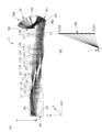
- FIG. 1 is an overall configuration diagram of an optical system 1 according to the present embodiment
- FIG. FIG. 2A is a layout diagram showing an optical system 1 according to a reference example.
- FIG. 2(B) is an explanatory diagram showing how an image projection apparatus using the optical system 1 according to the reference example is used.
- FIG. 3A is a Y sectional view showing an optical path through which a principal ray passes in the optical system 1 according to the reference example.
- FIG. 3B is an X cross-sectional view of the optical system 1 viewed from above.
- FIG. 4A is an explanatory diagram showing a position FLD1 closest to the optical system and a position FLD2 farthest from the optical system among the enlarged conjugate points in the optical system 1 according to the reference example.
- FIG. 4B is a lateral aberration diagram of reference rays at positions FLD1 and FLD2 in the optical system 1 according to the reference example.
- FIG. 4C is a lateral aberration diagram of the reference ray at the intermediate imaging position IM in the optical system 1 according to the reference example.
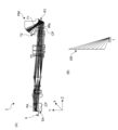
- 5A is a layout diagram showing the optical system 1 according to the first embodiment.
- FIG. 5B is an explanatory diagram showing a usage mode of the image projection apparatus using the optical system 1 according to the first embodiment.
- 6A is an explanatory diagram showing a position FLD1 closest to the optical system and a position FLD2 farthest from the optical system among the enlarged conjugate points in the optical system 1 according to Example 1;
- 6B is a lateral aberration diagram of the reference light beam at positions FLD1 and FLD2 in the optical system 1 according to Example 1.
- FIG. 6C is a lateral aberration diagram of the reference ray at the intermediate imaging position IM in the optical system 1 according to Example 1.
- FIG. 7A is a layout diagram showing an optical system 1 according to Example 2.
- FIG. FIG. 7B is an explanatory diagram showing a usage mode of an image projection apparatus using the optical system 1 according to the second embodiment.
- FIG. 8A is an explanatory diagram showing a position FLD1 closest to the optical system and a position FLD2 farthest from the optical system among the enlarged conjugate points in the optical system 1 according to Example 2;
- 8B is a lateral aberration diagram of the reference light beam at positions FLD1 and FLD2 in the optical system 1 according to Example 2.
- FIG. 8C is a lateral aberration diagram of the reference ray at the intermediate imaging position IM in the optical system 1 according to Example 2.
- FIG. 9A is a layout diagram showing an optical system 1 according to Example 3.
- FIG. 9B is an explanatory diagram showing how the image projection apparatus using the optical system 1 according to the third embodiment is used.
- FIG. 10A is an explanatory diagram showing a position FLD1 closest to the optical system and a position FLD2 farthest from the optical system among the enlarged conjugate points in the optical system 1 according to Example 3;
- 10B is a lateral aberration diagram of the reference light beam at positions FLD1 and FLD2 in the optical system 1 according to Example 3.
- FIG. 10C is a lateral aberration diagram of the reference ray at the intermediate imaging position IM in the optical system 1 according to Example 3.
- FIG. FIG. 11A is a layout diagram showing an optical system 1 according to Example 4;
- FIG. 11B is an explanatory diagram showing how the image projection apparatus using the optical system 1 according to the fourth embodiment is used.
- FIG. 12A is an explanatory diagram showing a position FLD1 closest to the optical system and a position FLD2 farthest from the optical system among the enlarged conjugate points in the optical system 1 according to Example 4;
- 12B is a lateral aberration diagram of reference light rays at positions FLD1 and FLD2 in the optical system 1 according to Example 4.
- FIG. 12C is a lateral aberration diagram of the reference ray at the intermediate imaging position IM in the optical system 1 according to Example 4.
- FIG. 13A is a layout diagram showing an optical system 1 according to Example 5.
- FIG. FIG. 13B is an explanatory diagram showing how the image projection apparatus using the optical system 1 according to the fifth embodiment is used.
- FIG. 14A is a Y sectional view showing an optical path through which a principal ray passes in the optical system 1 according to Example 5.
- FIG. 14B is an X sectional view of the optical system 1 viewed from above.
- 15A is an explanatory diagram showing a position FLD1 closest to the optical system and a position FLD2 farthest from the optical system among the enlarged conjugate points in the optical system 1 according to Example 5.
- FIG. 15B is a lateral aberration diagram of reference light rays at positions FLD1 and FLD2 in the optical system 1 according to Example 5.
- FIG. 15C is a lateral aberration diagram of the reference ray at the intermediate imaging position IM in the optical system 1 according to Example 5.
- FIG. 16A is a layout diagram showing an optical system 1 according to Example 6.
- FIG. FIG. 16B is an explanatory diagram showing how the image projection apparatus using the optical system 1 according to the sixth embodiment is used.
- FIG. 17A is an explanatory diagram showing a position FLD1 closest to the optical system and a position FLD2 farthest from the optical system among the enlarged conjugate points in the optical system 1 according to Example 6; 17B is a lateral aberration diagram of the reference light beam at positions FLD1 and FLD2 in the optical system 1 according to Example 6.
- FIG. 17C is a lateral aberration diagram of the reference ray at the intermediate imaging position IM in the optical system 1 according to Example 6.
- FIG. 18A is a layout diagram showing an optical system 1 according to Example 7.
- FIG. 18B is an explanatory diagram showing how the image projection apparatus using the optical system 1 according to the seventh embodiment is used.
- 19A is a layout diagram showing an optical system 1 according to Example 8.
- FIG. 19B is an explanatory diagram showing a usage mode of an image projection apparatus using the optical system 1 according to the eighteenth embodiment.
- 20A is a layout diagram showing an optical system 1 according to Example 9.
- FIG. 20B is an explanatory diagram showing how the image projection apparatus using the optical system 1 according to the ninth embodiment is used.
- FIG. 21A is a layout diagram showing the optical system 1 according to the tenth embodiment.
- FIG. 21B is an explanatory diagram showing a usage mode of an image projection apparatus using the optical system 1 according to the tenth embodiment.
- FIG. 23A is a cross-sectional view in the Y direction showing various examples of the stepped structure of the prism PM according to Examples 1 to 4; 23B is a cross-sectional view in the Y direction showing various examples of the stepped structure of the prism PM according to the fifth embodiment;
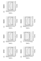
- FIG. 24A to 24G are graphs showing shapes of rectangular regions and concentric circles at reduced conjugate points in Numerical Reference Example and Numerical Examples 1 to 6.
- 25A to 25G are graphs showing distortion shapes at conjugate points on the enlargement side due to distortion aberration of optical systems according to Numerical Reference Example and Numerical Examples 1 to 6.
- FIG. 26A is a graph showing the relationship between the refractive index of the prism PM and the optical total length.
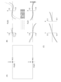
- FIG. 26B is a graph showing the relationship between the formula (1) and the optical total length; Block diagram showing an example of an image projection device according to the present disclosure Block diagram showing an example of an imaging device according to the present disclosure
- the optical system is a projector (image projection system) that projects onto a screen image light of an original image SA obtained by spatially modulating incident light by an image forming device such as a liquid crystal or a DMD (digital micromirror device) based on an image signal.
- an image forming device such as a liquid crystal or a DMD (digital micromirror device)
- an image forming device such as a liquid crystal or a DMD (digital micromirror device)
- the optical system according to the present disclosure can be used to arrange a screen (not shown) on the extension of the enlargement side, and to enlarge the original image SA on the image forming element arranged on the reduction side and project it on the screen.
- the projection surface is not limited to the screen.
- the projection surface includes walls, ceilings, floors, windows, etc. of houses, shops, and vehicles and aircraft used for means of transportation.
- the optical system according to the present disclosure collects light emitted from an object positioned on an extension line on the enlargement side, and forms an optical image of the object on the imaging surface of the imaging device arranged on the reduction side. is also available.
- Embodiment 1 An optical system according to Embodiment 1 of the present disclosure will be described below with reference to FIGS. 1 to 26.
- FIG. 2A is a layout diagram showing an optical system 1 according to a reference example.
- the optical system 1 has a reduction-side reduction conjugate point positioned on the left side of the drawing and an expansion-side expansion conjugate point positioned on the right side of the drawing.
- the optical system 1 is provided on the enlargement side, a prism PM formed of a transparent medium, and a sub-optical system provided between the reduction conjugate point and the prism PM and having a plurality of optical elements L1 to L18 and an aperture stop ST. and
- the image area at the reduced conjugate point is defined as a rectangular area having a longitudinal direction (X direction) and a transverse direction (Y direction), and has an imaging relationship that is optically conjugate with the image area at the enlarged conjugate point. .
- the ray travels along the normal direction (Z direction) of this rectangular area.
- This rectangular area has aspect ratios such as 3:2, 4:3, 16:9, 16:10, 256:135, for example, and corresponds to the image display area of the image forming element in the case of an image projection device. However, in the case of an image pickup device, it corresponds to the image pickup area of the image sensor.
- an intermediate imaging position that is conjugate with the reduction conjugate point and the expansion conjugate point, respectively, is located inside the optical system 1.
- This intermediate imaging position is shown as the Y-direction intermediate image IMy in FIG. 2A, but the X-direction intermediate image IMx is omitted.
- the sub-optical system includes an optical element PA and lens elements L1 to L18 in order from the reduction side to the enlargement side.
- the optical element PA represents an optical element such as a TIR (total internal reflection) prism, a prism for color separation and color synthesis, an optical filter, parallel plate glass, a crystal low-pass filter, an infrared cut filter, and the like.
- a reduction-side end surface of the optical element PA is set at a reduction conjugate point, where the original image SA is placed (surface 1). For the surface numbers, refer to Numerical Examples to be described later.
- the optical element PA has two parallel and flat transmission surfaces (surfaces 2 and 3).
- Lens element L1 has a positive meniscus shape with a convex surface facing the reduction side (surfaces 4 and 5).
- Lens element L2 has a negative meniscus shape with a convex surface facing the reduction side (surfaces 6 and 7).
- Lens element L3 has a biconvex shape (surfaces 7, 8).
- Lens element L4 has a negative meniscus shape with a convex surface facing the magnification side (surfaces 8 and 9).
- Lens elements L2-L4 are cemented together to form a compound lens.
- Lens element L5 has a biconvex shape (surfaces 10, 11).
- Lens element L6 has a biconcave shape (surfaces 11, 12).
- Lens elements L5 and L6 are cemented together to form a compound lens.
- Lens element L7 has a negative meniscus shape with a convex surface facing the reduction side (surfaces 13, 14).
- Lens element L8 has a biconvex shape (surfaces 14, 15).
- Lens elements L7 and L8 are cemented together to form a compound lens.
- the aperture stop ST defines the range through which the light beam passes through the optical system 1, and is positioned between the reduction conjugate point and the intermediate imaging position described above.
- aperture stop ST is located between lens element L8 and lens element L9 (surface 16).
- the lens element L9 has a biconvex shape (surfaces 17, 18).
- Lens element L10 has a negative meniscus shape with a convex surface facing the magnification side (surfaces 18, 19).
- Lens elements L9 and L10 are cemented together to form a compound lens.
- Lens element L11 has a negative meniscus shape with a convex surface facing the magnification side (surfaces 20, 21).
- the lens element L12 has a positive meniscus shape with a convex surface facing the magnification side (surfaces 21 and 22).
- Lens elements L11 and L12 are cemented together to form a compound lens.
- Lens element L13 has a biconvex shape (surfaces 23, 24).
- Lens element L14 has a biconvex shape (surfaces 25, 26).
- Lens element L15 has a biconcave shape (surfaces 27, 28).
- Lens element L16 has a biconvex shape (surfaces 28, 29).
- Lens elements L15 and L16 are cemented together to form a compound lens.
- Lens element L17 has a negative meniscus shape with a convex surface facing the reduction side (surfaces 30, 31).
- Lens element L18 has a positive meniscus shape with a convex surface facing the magnification side (surfaces 32, 33).
- the prism PM can be made of a transparent medium such as glass or synthetic resin.
- the prism PM has a first transmission surface T1 located on the reduction side, a second transmission surface T2 located on the expansion side, and two transmission surfaces located on the optical path between the first transmission surface T1 and the second transmission surface T2. It has a first reflecting surface R1 and a second reflecting surface R2.
- the first transmission surface T1 has a free-form surface shape with a concave surface facing the reduction side (surface 34).
- the first reflective surface R1 has a free-form surface shape (surface 35) in which the concave surface faces the direction in which the light rays incident on the first reflective surface R1 are reflected.
- the second reflecting surface R2 has a planar shape (surface 36).
- the second transmission surface T2 has a free-form surface shape with a convex surface facing the enlargement side (surface 37).
- FIG. 2(B) is an explanatory diagram showing how an image projection apparatus using the optical system 1 according to the reference example is used.
- An image projection apparatus including the optical system 1 is placed horizontally on a support base such as a table or on the floor.
- a screen SR is placed vertically above the support at a relatively short horizontal distance, eg, 0.7 m.
- the light emitted from the optical system 1 is projected obliquely forward and upward, realizing short-focus and large-screen projection. Therefore, a space for people to move can be formed in front of the screen SR, and the degree of freedom in installing the image projection apparatus can be increased.
- FIG. 3(A) is a Y sectional view showing the optical path through which the principal ray passes in the optical system 1 according to the reference example
- FIG. 3(B) is an X sectional view when the optical system 1 is viewed from above.
- a chief ray is defined as "the ray that passes through the center of the aperture stop, or the ray that passes through the midpoint from either end of the aperture stop at any cross-section".
- FIG. 3B shows the principal ray passing through the left end of the original image SA in the X direction and the principal ray passing through the right end of the original image SA in the X direction.
- Both principal rays pass through the sub-optical system, pass through the transmission surface T1, enter the interior of the prism PM, are then reflected by the reflection surface R1, and enter the area indicated by the dashed circle before reaching the reflection surface R2. cross each other at CRx.
- FIG. 3A when viewed from the direction perpendicular to the Y cross section, some of the plurality of principal rays passing through the reduction conjugate point are on the optical path between the reflecting surface R1 and the transmitting surface T2.
- FIG. 3B when viewed from the direction perpendicular to the X cross section, some of the plurality of principal rays passing through the reduction conjugate point pass through the reflecting surface R1.
- the curvature shape of the free-form surface of the reflecting surface R1 is set so as to intersect with the surface T2 on the optical path.
- FIG. 4A is an explanatory diagram showing a position FLD1 closest to the optical system and a position FLD2 farthest from the optical system among the enlarged conjugate points in the optical system 1 according to the reference example.
- FIG. 4B is a lateral aberration diagram of reference rays at positions FLD1 and FLD2 in the optical system 1 according to the reference example.
- FIG. 4C is a lateral aberration diagram of the reference ray at the intermediate imaging position IM that is conjugate with the reduction conjugate point of the sub-optical system in the optical system 1 according to the reference example. Note that FIG. 4C shows the imaging position in the air.
- a solid line is a wavelength of 587.5600 nm
- a dashed line is a wavelength of 656.2700 nm
- a dashed line is a wavelength of 435.8300 nm.
- FIG. 5A is a layout diagram showing the optical system 1 according to the first embodiment.
- FIG. 7A is a layout diagram showing the optical system 1 according to the second embodiment.
- the intermediate imaging positions that are conjugate with the reduced conjugate point and the enlarged conjugate point are shown as the Y-direction intermediate image IMy in the drawing.
- the illustration of the X-direction intermediate image IMx is omitted.
- the optical element PA has two parallel and flat transmission surfaces (surfaces 2 and 3).
- Lens element L1 has a positive meniscus shape with a convex surface facing the reduction side (surfaces 4 and 5).
- Lens element L2 has a negative meniscus shape with a convex surface facing the reduction side (surfaces 6 and 7).
- Lens element L3 has a biconvex shape (surfaces 7, 8).
- Lens element L4 has a negative meniscus shape with a convex surface facing the magnification side (surfaces 8 and 9).
- Lens elements L2-L4 are cemented together to form a compound lens.
- Lens element L5 has a biconvex shape (surfaces 10, 11).
- Lens element L6 has a biconcave shape (surfaces 11, 12).
- Lens elements L5 and L6 are cemented together to form a compound lens.
- Lens element L7 has a negative meniscus shape with a convex surface facing the reduction side (surfaces 13, 14).
- Lens element L8 has a biconvex shape (surfaces 14, 15).
- Lens elements L7 and L8 are cemented together to form a compound lens.
- the aperture stop ST defines the range through which the light beam passes through the optical system 1, and is positioned between the reduction conjugate point and the intermediate imaging position described above.
- aperture stop ST is located between lens element L8 and lens element L9 (surface 16).
- the lens element L9 has a biconvex shape (surfaces 17, 18).
- Lens element L10 has a negative meniscus shape with a convex surface facing the magnification side (surfaces 18, 19).
- Lens elements L9 and L10 are cemented together to form a compound lens.
- Lens element L11 has a negative meniscus shape with a convex surface facing the magnification side (surfaces 20, 21).
- the lens element L12 has a positive meniscus shape with a convex surface facing the magnification side (surfaces 21 and 22).
- Lens elements L11 and L12 are cemented together to form a compound lens.
- Lens element L13 has a biconvex shape (surfaces 23, 24).
- Lens element L14 has a biconvex shape (surfaces 25, 26).
- Lens element L15 has a biconcave shape (surfaces 27, 28).
- Lens element L16 has a biconvex shape (surfaces 28, 29).
- Lens elements L15 and L16 are cemented together to form a compound lens.
- Lens element L17 has a negative meniscus shape with a convex surface facing the reduction side (surfaces 30, 31).
- Lens element L18 has a positive meniscus shape with a convex surface facing the magnification side (surfaces 32, 33).
- the prism PM can be made of a transparent medium such as glass or synthetic resin.
- the prism PM has a first transmission surface T1 located on the reduction side, a second transmission surface T2 located on the expansion side, and two transmission surfaces located on the optical path between the first transmission surface T1 and the second transmission surface T2. It has a first reflecting surface R1 and a second reflecting surface R2.
- the first transmission surface T1 has a free-form surface shape with a concave surface facing the reduction side (surface 34).
- the first reflective surface R1 has a free-form surface shape (surface 35) in which the concave surface faces the direction in which the light rays incident on the first reflective surface R1 are reflected.
- the second reflecting surface R2 has a planar shape (surface 36).
- the second transmission surface T2 has a free-form surface shape with a convex surface facing the enlargement side (surface 37).
- the prism PM integrates the first transmitting surface T1, the second transmitting surface T2, the first reflecting surface R1, and the second reflecting surface R2, it is possible to reduce assembly adjustment between optical components and reduce the number of optical components. can reduce costs from
- the optical surfaces having the power of the prism PM for example, the first transmitting surface T1, the second transmitting surface T2, and the first reflecting surface R1, do not have a rotationally symmetrical axis. It is formed as a free curved surface of curvature.
- the degree of freedom for satisfactorily correcting distortion is increased, and an effect of shortening the total length of the first sub-optical system can be expected.
- the weight of the head portion of the optical system 1 can be reduced, the center of gravity of the optical system can be arranged in a well-balanced manner, and the structure of the connecting portion for holding the lens barrel of the optical system to the casing of the optical system can be simplified. .
- FIG. 5(B) is an explanatory diagram showing how the image projection apparatus using the optical system 1 according to the first embodiment is used.
- FIG. 7B is an explanatory diagram showing how an image projection apparatus using the optical system 1 according to the second embodiment is used.
- An image projection apparatus including the optical system 1 is placed horizontally on a support base such as a table or on the floor.
- a screen SR is placed vertically above the support at a relatively short horizontal distance, eg, 0.7 m.
- the light emitted from the optical system 1 is projected obliquely forward and upward, realizing short-focus and large-screen projection. Therefore, a space for people to move can be formed in front of the screen SR, and the degree of freedom in installing the image projection apparatus can be increased.
- FIGS. 6(A) and 8(A) are explanations showing a position FLD1 closest to the optical system and a position FLD2 farthest from the optical system among the enlarged conjugate points in the optical system 1 according to Examples 1 and 2. It is a diagram.
- FIGS. 6B and 8B are lateral aberration diagrams of reference rays at positions FLD1 and FLD2 in the optical system 1 according to Examples 1 and 2.
- FIG. 6C and 8C are lateral aberration diagrams of the reference ray at the intermediate imaging position IM conjugate with the reduction conjugate point of the sub-optical system in the optical system 1 according to Examples 1 and 2.
- FIG. 6(C) and 8(C) show image formation positions in the air.
- a solid line is a wavelength of 587.5600 nm
- a dashed line is a wavelength of 656.2700 nm
- a dashed line is a wavelength of 435.8300 nm.
- FIG. 9A is a layout diagram showing an optical system 1 according to Example 3.
- FIG. This optical system 1 has a configuration similar to that of the reference example and the first and second examples, but hereinafter, the explanation overlapping with the reference example and the first and second examples may be omitted.
- the intermediate imaging positions that are conjugate with the reduced conjugate point and the enlarged conjugate point are shown as the Y-direction intermediate image IMy in the drawing.
- the illustration of the X-direction intermediate image IMx is omitted.
- the optical element PA has two parallel and flat transmission surfaces (surfaces 2 and 3).
- Lens element L1 has a positive meniscus shape with a convex surface facing the reduction side (surfaces 4 and 5).
- Lens element L2 has a negative meniscus shape with a convex surface facing the reduction side (surfaces 6 and 7).
- Lens element L3 has a biconvex shape (surfaces 7, 8).
- Lens element L4 has a negative meniscus shape with a convex surface facing the magnification side (surfaces 8 and 9).
- Lens elements L2-L4 are cemented together to form a compound lens.
- Lens element L5 has a biconvex shape (surfaces 10, 11).
- Lens element L6 has a biconcave shape (surfaces 11, 12).
- Lens elements L5 and L6 are cemented together to form a compound lens.
- Lens element L7 has a negative meniscus shape with a convex surface facing the reduction side (surfaces 13, 14).
- Lens element L8 has a biconvex shape (surfaces 14, 15).
- Lens elements L7 and L8 are cemented together to form a compound lens.
- the aperture stop ST defines the range through which the light beam passes through the optical system 1, and is positioned between the reduction conjugate point and the intermediate imaging position described above.
- aperture stop ST is located between lens element L8 and lens element L9 (surface 16).
- the lens element L9 has a biconvex shape (surfaces 17, 18).
- Lens element L10 has a negative meniscus shape with a convex surface facing the magnification side (surfaces 19, 20).
- the lens element L11 has a positive meniscus shape with a convex surface facing the magnification side (surfaces 20, 21).
- Lens elements L10 and L11 are cemented together to form a compound lens.
- Lens element L12 has a biconvex shape (surfaces 22, 23).
- Lens element L13 has a biconvex shape (surfaces 24, 25).
- Lens element L14 has a biconcave shape (surfaces 26, 27).
- Lens element L15 has a biconvex shape (surfaces 27, 28).
- Lens elements L14 and L15 are cemented together to form a compound lens.
- Lens element L16 has a negative meniscus shape with a convex surface facing the reduction side (surfaces 29, 30).
- the lens element L17 has a positive meniscus shape with a convex
- the prism PM can be made of a transparent medium such as glass or synthetic resin.
- the prism PM has a first transmission surface T1 located on the reduction side, a second transmission surface T2 located on the expansion side, and two transmission surfaces located on the optical path between the first transmission surface T1 and the second transmission surface T2. It has a first reflecting surface R1 and a second reflecting surface R2.
- the first transmission surface T1 has a free-form surface shape with a concave surface facing the reduction side (surface 33).
- the first reflective surface R1 has a free-form surface shape (surface 34) in which the concave surface faces the direction in which the light rays incident on the first reflective surface R1 are reflected.
- the second reflecting surface R2 has a planar shape (surface 35).
- the second transmission surface T2 has a free-form surface shape with a convex surface facing the enlargement side (surface 36).
- FIG. 9(B) is an explanatory diagram showing how an image projection apparatus using the optical system 1 according to the third embodiment is used.
- An image projection apparatus including the optical system 1 is placed horizontally on a support base such as a table or on the floor.
- a screen SR is placed vertically above the support at a relatively short horizontal distance, eg, 0.7 m.
- the light emitted from the optical system 1 is projected obliquely forward and upward, realizing short-focus and large-screen projection. Therefore, a space for people to move can be formed in front of the screen SR, and the degree of freedom in installing the image projection apparatus can be increased.
- FIG. 10A is an explanatory diagram showing a position FLD1 closest to the optical system and a position FLD2 farthest from the optical system among the enlarged conjugate points in the optical system 1 according to Example 3.
- FIG. 10B is a lateral aberration diagram of reference rays at positions FLD1 and FLD2 in the optical system 1 according to Example 3.
- FIG. 10C is a lateral aberration diagram of the reference ray at the intermediate imaging position IM that is conjugate with the reduction conjugate point of the sub-optical system in the optical system 1 according to Example 3.
- FIG. Note that FIG. 10C shows the imaging position in the air.
- a solid line is a wavelength of 587.5600 nm
- a dashed line is a wavelength of 656.2700 nm
- a dashed line is a wavelength of 435.8300 nm.
- FIG. 11A is a layout diagram showing an optical system 1 according to Example 4.
- FIG. This optical system 1 has the same configuration as that of the reference example and Examples 1 to 3, but the description overlapping with the reference example and Examples 1 to 3 may be omitted.
- the intermediate imaging positions that are conjugate with the reduced conjugate point and the enlarged conjugate point are shown as the Y-direction intermediate image IMy in the drawing.
- the illustration of the X-direction intermediate image IMx is omitted.
- the optical element PA has two parallel and flat transmission surfaces (surfaces 2 and 3).
- Lens element L1 has a positive meniscus shape with a convex surface facing the reduction side (surfaces 4 and 5).
- Lens element L2 has a negative meniscus shape with a convex surface facing the reduction side (surfaces 6 and 7).
- Lens element L3 has a biconvex shape (surfaces 7, 8).
- Lens element L4 has a negative meniscus shape with a convex surface facing the magnification side (surfaces 8 and 9).
- Lens elements L2-L4 are cemented together to form a compound lens.
- Lens element L5 has a biconvex shape (surfaces 10, 11).
- Lens element L6 has a biconcave shape (surfaces 11, 12).
- Lens elements L5 and L6 are cemented together to form a compound lens.
- Lens element L7 has a negative meniscus shape with a convex surface facing the reduction side (surfaces 13, 14).
- Lens element L8 has a biconvex shape (surfaces 14, 15).
- Lens elements L7 and L8 are cemented together to form a compound lens.
- the aperture stop ST defines the range through which the light beam passes through the optical system 1, and is positioned between the reduction conjugate point and the intermediate imaging position described above.
- aperture stop ST is located between lens element L8 and lens element L9 (surface 16).
- the lens element L9 has a biconvex shape (surfaces 17, 18).
- Lens element L10 has a negative meniscus shape with a convex surface facing the magnification side (surfaces 19, 20).
- Lens element L11 has a biconvex shape (surfaces 21, 22).
- Lens element L12 has a biconvex shape (surfaces 23, 24).
- Lens element L13 has a biconcave shape (surfaces 25, 26).
- Lens element L14 has a biconvex shape (surfaces 26, 27).
- Lens elements L13 and L14 are cemented together to form a compound lens.
- Lens element L15 has a negative meniscus shape with a convex surface facing the reduction side (surfaces 28, 29).
- Lens element L16 has a positive meniscus shape with a convex surface facing the magnification side (surfaces 30, 31).
- the prism PM can be made of a transparent medium such as glass or synthetic resin.
- the prism PM has a first transmission surface T1 located on the reduction side, a second transmission surface T2 located on the expansion side, and two transmission surfaces located on the optical path between the first transmission surface T1 and the second transmission surface T2. It has a first reflecting surface R1 and a second reflecting surface R2.
- the first transmission surface T1 has a free-form surface shape with a concave surface facing the reduction side (surface 32).
- the first reflecting surface R1 has a free-form surface shape (surface 33) with a concave surface facing the direction in which the light rays incident on the first reflecting surface R1 are reflected.
- the second reflecting surface R2 has a planar shape (surface 34).
- the second transmission surface T2 has a free-form surface shape with a convex surface facing the enlargement side (surface 35).
- FIG. 11(B) is an explanatory diagram showing how an image projection apparatus using the optical system 1 according to the fourth embodiment is used.
- An image projection apparatus including the optical system 1 is placed horizontally on a support base such as a table or on the floor.
- a screen SR is placed vertically above the support at a relatively short horizontal distance, eg, 0.7 m.
- the light emitted from the optical system 1 is projected obliquely forward and upward, realizing short-focus and large-screen projection. Therefore, a space for people to move can be formed in front of the screen SR, and the degree of freedom in installing the image projection apparatus can be increased.
- FIG. 12A is an explanatory diagram showing a position FLD1 closest to the optical system and a position FLD2 farthest from the optical system among the enlarged conjugate points in the optical system 1 according to Example 4.
- FIG. 12B is a lateral aberration diagram of reference rays at positions FLD1 and FLD2 in the optical system 1 according to Example 4.
- FIG. 12C is a lateral aberration diagram of the reference ray at the intermediate imaging position IM that is conjugate with the reduction conjugate point of the sub-optical system in the optical system 1 according to Example 4.
- FIG. Note that FIG. 12C shows the imaging position in the air.
- a solid line is a wavelength of 587.5600 nm
- a dashed line is a wavelength of 656.2700 nm
- a dashed line is a wavelength of 435.8300 nm.
- FIG. 13A is a layout diagram showing an optical system 1 according to Example 5.
- FIG. This optical system 1 has the same configuration as that of the reference example and Examples 1 to 4, but the description overlapping with the reference example and Examples 1 to 4 may be omitted.
- intermediate imaging positions that are conjugate with the reduction conjugate point and the expansion conjugate point, respectively, and are shown as Y-direction intermediate images IMy in the drawing.
- the illustration of the X-direction intermediate image IMx is omitted.
- An intermediate image IMy formed at the first intermediate imaging position intersects the lens element L12 of the sub-optical system and is positioned between the lens elements L11 and L13. Part or all of the intermediate image IMy formed at the second intermediate imaging position is positioned inside the medium of the prism PM.
- the first intermediate image-forming position is not limited to between the lens element L11 and the lens element L12. Further shortening is possible.
- the number of intermediate imaging positions is the number of conjugate points between the contraction conjugate point and the expansion conjugate point on a specific ray. is the number of intermediate imagings.
- the optical element PA has two parallel and flat transmission surfaces (surfaces 2 and 3).
- Lens element L1 has a negative meniscus shape with a convex surface facing the magnification side (surfaces 4, 5).
- Lens element L2 has a biconvex shape (faces 6, 7).
- Lens element L3 has a biconvex shape (surfaces 8, 9).
- Lens element L4 has a biconvex shape (surfaces 10, 11).
- Lens element L5 has a biconcave shape (surfaces 11, 12). Lens elements L4 and L5 are cemented together to form a compound lens.
- the aperture stop ST defines the range through which the light beam passes through the optical system 1, and is positioned between the reduction conjugate point and the intermediate imaging position described above, preferably between the second intermediate imaging position. be done.
- aperture stop ST is located between lens element L5 and lens element L6 (surface 13).
- Lens element L6 has a biconcave shape (surfaces 14, 15).
- Lens element L7 has a biconvex shape (surfaces 15, 16).
- Lens elements L6 and L7 are cemented together to form a compound lens.
- Lens element L8 has a biconvex shape (surfaces 17, 18).
- Lens element L9 has a biconvex shape (surfaces 19, 20).
- Lens element L10 has a negative meniscus shape with a convex surface facing the magnification side (surfaces 21, 22).
- the lens element L11 has a positive meniscus shape with a convex surface facing the reduction side (surfaces 23, 24).
- Lens element L12 has a biconcave shape (surfaces 25, 26).
- Lens element L13 has a biconvex shape (surfaces 27, 28).
- Lens element L14 has a biconvex shape (surfaces 29, 30).
- the lens element L15 has a positive meniscus shape with a convex surface facing the magnification side (surfaces 31, 32).
- Lens element L16 has a negative meniscus shape with a convex surface facing the reduction side (surfaces 33, 34).
- Lens element L17 has a biconcave shape (surfaces 34, 35). Lens elements L16 and L17 are cemented together to form a compound lens.
- Lens element L18 has a biconvex shape (surfaces 36, 37).
- Lens element L19 has a biconcave shape (surfaces 38, 39).
- Lens element L20 has a biconvex shape (surfaces 40, 41).
- Lens element L21 has a biconvex shape (surfaces 42, 43).
- Lens element L22 has a negative meniscus shape with a convex surface facing the magnification side (surfaces 44, 45).
- Lens element L23 has a biconvex shape (surfaces 46, 47).
- Lens element L24 has a biconvex shape (surfaces 48, 49).
- Lens element L25 has a biconcave shape (surfaces 50, 51).
- the lens element L26 has a positive meniscus shape with a convex surface facing the reduction side (surfaces 52, 53).
- Lens element L27 has a biconvex shape (surfaces 54, 55).
- the prism PM has a first transmission surface T1 located on the reduction side, a second transmission surface T2 located on the expansion side, and two transmission surfaces located on the optical path between the first transmission surface T1 and the second transmission surface T2. It has a first reflecting surface R1 and a second reflecting surface R2.
- the first transmission surface T1 has a free-form surface shape with a concave surface facing the reduction side (surface 56).
- the first reflective surface R1 has a free-form surface shape (surface 57) with a concave surface facing the direction in which the light rays incident on the first reflective surface R1 are reflected.
- the second reflecting surface R2 has a planar shape (surface 58).
- the second transmission surface T2 has a free-form surface shape with a convex surface facing the enlargement side (surface 59).
- FIG. 13(B) is an explanatory diagram showing how an image projection apparatus using the optical system 1 according to the fifth embodiment is used.
- An image projection apparatus including the optical system 1 is placed horizontally on a support base such as a table or on the floor.
- a screen SR is placed horizontally forward at a relatively short horizontal distance, eg, 0.2 m, from the support.
- the light emitted from the optical system 1 is projected obliquely forward and downward, realizing short-focus and large-screen projection. Therefore, a space for people to move can be formed in front of the screen SR, and the degree of freedom in installing the image projection apparatus can be increased.
- the screen SR and the image projection device can be arranged substantially parallel, short-focus and large-screen projection can be realized even in a place where the space for arranging the screen SR and the image projection device is narrow.
- FIG. 14A is a Y sectional view showing the optical path through which the principal ray passes in the optical system 1 according to Example 5, and FIG. 14B is an X sectional view when the optical system 1 is viewed from above. is.
- Both principal rays pass through the sub-optical system, pass through the transmission surface T1, enter the interior of the prism PM, are then reflected by the reflection surface R1, and enter the area indicated by the dashed circle before reaching the reflection surface R2. cross each other at CRy.
- FIG. 14(B) shows a principal ray passing through the left end of the original image SA in the X direction and a principal ray passing through the right end of the original image SA in the X direction.
- Both principal rays pass through the sub-optical system, pass through the transmission surface T1, enter the interior of the prism PM, are then reflected by the reflection surface R1, and enter the area indicated by the dashed circle before reaching the reflection surface R2. cross each other at CRx.
- FIG. 14A when viewed from the direction perpendicular to the Y cross section, some of the plurality of principal rays passing through the reduction conjugate point are on the optical path between the reflecting surface R1 and the transmitting surface T2.
- FIG. 14(B) when viewed from the direction perpendicular to the X cross section, some of the plurality of principal rays passing through the reduction conjugate point pass through the reflecting surface R1.
- the curvature shape of the free-form surface of the reflecting surface R1 is set so as to intersect with the surface T2 on the optical path.
- FIG. 15(A) is an explanatory diagram showing a position FLD1 closest to the optical system and a position FLD2 farthest from the optical system among the enlarged conjugate points in the optical system 1 according to Example 5.
- FIG. FIG. 15B is a lateral aberration diagram of reference rays at positions FLD1 and FLD2 in the optical system 1 according to Example 5.
- FIG. 15C is a lateral aberration diagram of the reference ray at the second intermediate imaging position IM in the optical system 1 according to Example 5.
- FIG. Note that FIG. 15C shows the imaging position in the air.
- a solid line is a wavelength of 587.5600 nm
- a dashed line is a wavelength of 656.2700 nm
- a dashed line is a wavelength of 435.8300 nm.
- FIG. 16A is a layout diagram showing an optical system 1 according to Example 6.
- FIG. This optical system 1 has the same configuration as that of the reference example and Examples 1 to 5, but the description overlapping with the reference example and Examples 1 to 5 may be omitted.
- the intermediate imaging positions that are conjugate with the reduced conjugate point and the enlarged conjugate point are shown as the Y-direction intermediate image IMy in the drawing.
- the illustration of the X-direction intermediate image IMx is omitted.
- Example 6 a portion of the intermediate image IMy is formed between the first transmitting surface T1 and the first reflecting surface R1, and the remaining portion of the intermediate image IMy is formed between the sub-optical system and the prism PM.
- the optical element PA has two parallel and flat transmission surfaces (surfaces 2 and 3).
- Lens element L1 has a positive meniscus shape with a convex surface facing the reduction side (surfaces 4 and 5).
- Lens element L2 has a negative meniscus shape with a convex surface facing the reduction side (surfaces 6 and 7).
- Lens element L3 has a biconvex shape (surfaces 7, 8).
- Lens element L4 has a negative meniscus shape with a convex surface facing the magnification side (surfaces 8 and 9).
- Lens elements L2-L4 are cemented together to form a compound lens.
- Lens element L5 has a biconcave shape (surfaces 10, 11).
- Lens element L6 has a biconvex shape (surfaces 11, 12).
- Lens elements L5 and L6 are cemented together to form a compound lens.
- the aperture stop ST defines the range through which the light beam passes through the optical system 1, and is positioned between the reduction conjugate point and the intermediate imaging position described above.
- aperture stop ST is located between lens element L6 and lens element L7 (surface 13).
- the lens element L7 has a biconvex shape (surfaces 14, 15).
- Lens element L8 has a negative meniscus shape with a convex surface facing the magnification side (surfaces 16, 17).
- Lens element L9 has a biconvex shape (surfaces 18, 19).
- Lens element L10 has a biconvex shape (surfaces 20, 21).
- Lens element L11 has a biconcave shape (surfaces 21, 22).
- Lens elements L10 and L11 are cemented together to form a compound lens.
- Lens element L12 has a negative meniscus shape with a convex surface facing the reduction side (surfaces 23, 24).
- Lens element L13 has a biconvex shape (surfaces 25, 26).
- the prism PM can be made of a transparent medium such as glass or synthetic resin.
- the prism PM has a first transmission surface T1 located on the reduction side, a second transmission surface T2 located on the expansion side, and two transmission surfaces located on the optical path between the first transmission surface T1 and the second transmission surface T2. It has a first reflecting surface R1 and a second reflecting surface R2.
- the first transmission surface T1 has a free-form surface shape with a concave surface facing the reduction side (surface 27).
- the first reflecting surface R1 has a free-form surface shape (surface 28) with a concave surface facing the direction in which the light rays incident on the first reflecting surface R1 are reflected.
- the second reflecting surface R2 has a planar shape (surface 29).
- the second transmission surface T2 has a free-form surface shape with a convex surface facing the enlargement side (surface 30).
- FIG. 16(B) is an explanatory diagram showing how an image projection apparatus using the optical system 1 according to Example 6 is used.
- An image projection apparatus including the optical system 1 is placed horizontally on a support base such as a table or on the floor.
- a screen SR is placed horizontally forward at a relatively short horizontal distance, eg, 0.2 m, from the support.
- the light emitted from the optical system 1 is projected obliquely forward and downward, realizing short-focus and large-screen projection. Therefore, a space for people to move can be formed in front of the screen SR, and the degree of freedom in installing the image projection apparatus can be increased.
- the screen SR and the image projection device can be arranged substantially parallel, short-focus and large-screen projection can be realized even in a place where the space for arranging the screen SR and the image projection device is narrow.
- FIG. 17A is an explanatory diagram showing a position FLD1 closest to the optical system and a position FLD2 farthest from the optical system among the enlarged conjugate points in the optical system 1 according to Example 6.
- FIG. 17B is a lateral aberration diagram of reference rays at positions FLD1 and FLD2 in the optical system 1 according to Example 6.
- FIG. 17C is a lateral aberration diagram of the reference ray at the intermediate imaging position IM that is conjugate with the reduction conjugate point of the sub-optical system in the optical system 1 according to Example 6.
- FIG. Note that FIG. 17C shows the imaging position in the air.
- a solid line is a wavelength of 587.5600 nm
- a dashed line is a wavelength of 656.2700 nm
- a dashed line is a wavelength of 435.8300 nm.
- FIG. 18A is a layout diagram showing an optical system 1 according to Example 7.
- FIG. This optical system 1 has an optical design similar to that of Examples 1 to 4, but a plane mirror MR1 is interposed between the lens elements to bend the reference optical axis A at right angles within the YZ plane.
- FIG. 18(B) is an explanatory diagram showing how an image projection apparatus using the optical system 1 according to the seventh embodiment is used.
- An image projection apparatus including the optical system 1 is placed horizontally on a support base such as a table or on the floor.
- a screen SR is placed parallel to the ZX plane at a relatively short horizontal distance, eg, 0.6 m, from the support.
- the light emitted from the optical system 1 is projected obliquely to achieve short-focus and large-screen projection.
- FIG. 19A is a layout diagram showing an optical system 1 according to Example 8.
- FIG. This optical system 1 has an optical design similar to that of Examples 1 to 4, but a plane mirror MR2 is interposed between the lens elements to bend the reference optical axis A at right angles in the ZX plane.
- FIG. 19(B) is an explanatory diagram showing how an image projection apparatus using the optical system 1 according to the eighteenth embodiment is used.
- An image projection apparatus including the optical system 1 is placed horizontally on a support base such as a table or on the floor.
- a screen SR is placed parallel to the YZ plane at a relatively short horizontal distance, eg, 0.6 m, from the support. The light emitted from the optical system 1 is projected obliquely to achieve short-focus and large-screen projection.
- FIG. 20A is a layout diagram showing the optical system 1 according to the ninth embodiment.
- FIG. 21A is a layout diagram showing the optical system 1 according to the tenth embodiment.
- These optical systems 1 have optical designs similar to those of Examples 1 to 4, but the prism PM has a first transmission surface T1 located on the reduction side, a second transmission surface T2 located on the enlargement side, and a second transmission surface T2 located on the enlargement side. It has one first reflecting surface R1 positioned on the optical path between the first transmitting surface T1 and the second transmitting surface T2.
- the first transmission surface T1 has a free-form surface shape with a concave surface facing the reduction side.
- the first reflective surface R1 has a free-form surface shape with a concave surface directed in a direction in which light rays incident on the first reflective surface R1 are reflected.
- the second transmission surface T2 has a free-form surface shape with a convex surface facing the enlargement side.
- FIG. 20(B) is an explanatory diagram showing how the image projection apparatus using the optical system 1 according to the ninth embodiment is used.
- An image projection apparatus including the optical system 1 is placed horizontally on a support base such as a table or on the floor.
- a screen SR is installed vertically upwards at a relatively short horizontal distance, eg, 0.8 m, rearward from the support.
- the light emitted from the optical system 1 is projected obliquely upward to the rear, realizing short-focus and large-screen projection.
- FIG. 21(B) is an explanatory diagram showing how an image projection apparatus using the optical system 1 according to the tenth embodiment is used.
- An image projection apparatus including the optical system 1 is placed horizontally on a support base such as a table or on the floor.
- a screen SR is placed vertically upwards at a relatively short horizontal distance, eg, 0.6 m, rearward from the support.
- the light emitted from the optical system 1 is projected obliquely upward to the rear, realizing short-focus and large-screen projection. Therefore, short-focus and large-screen projection is realized while suppressing the size of the image projection apparatus in the height direction.
- the sub-optical systems included in Examples 1 to 10 each include three or more convex lenses between the aperture stop and the reduction conjugate point and between the aperture stop and the intermediate imaging position. ing.
- the image forming element is arranged on the reduction conjugate point side, the light from the image forming element is uniformly guided to the sub optical system.
- the prism PM by making the enlarged conjugate point side of the sub-optical system a substantially telecentric optical system, the spread of light rays incident on the prism PM is suppressed, and the size of the prism PM is reduced. has the effect of making the
- the optical element having the power that is arranged closest to the reduction conjugate point in the sub-optical system does not spread the light rays on the reduction conjugate point side, the approximately telecentric effect can be enhanced by arranging a positive lens.
- the second reflecting surface of the prism PM included in Examples 1 to 8 is not limited to a flat surface, and may be configured by a reflecting surface having a curvature.
- a reflecting surface having a curvature it is possible to increase the degree of freedom in the direction of the magnified conjugate point and to maintain good shape accuracy of the reflecting surface during processing of the prism PM.
- the convex surface or the concave surface may be directed in the direction in which light rays enter the second reflecting surface.
- the optical surface of the second reflecting surface may be a rotationally symmetrical spherical surface, an aspherical surface, or a rotationally asymmetrical free-form surface.
- Examples 1 to 8 have the second reflecting surface, and the convex surfaces of the first reflecting surface and the second transmitting surface are both arranged toward the enlarged conjugate point side.
- the luminous flux distribution (footprint) of the optical surface arranged on the enlargement side of the intermediate imaging position in the prism PM is the reference ray OAr imaged at the position closest to the optical system among the enlargement conjugate points on the screen SR.
- the luminous flux size is distributed so as to be the smallest. This is done by increasing the size of the luminous flux in proportion to the distance between the luminous flux passing through the prism PM and the conjugate point on the enlargement side, matching the imaging magnification of each luminous flux, and maintaining good distortion on the enlargement and reduction sides. can be done.
- each luminous flux distribution of the optical surface arranged on the enlargement side of the intermediate image forming position in the prism PM into a substantially elliptical shape having a major axis in the azimuth projected onto the XY plane in the direction in which each luminous flux travels.
- the magnification in the X direction and the Y direction on the enlarged conjugate point side of each luminous flux are matched to obtain the effect of being able to satisfactorily correct the distortion.
- Prism PM forms a reflecting surface on a part of a lens element or the like having a free-form optical surface, and has at least one reflecting surface located on the optical path between the first transmitting surface and the second transmitting surface.
- the prism PM forms a reflecting surface on a part of a lens element or the like having a decentered, rotationally symmetrical spherical surface or an aspherical optical surface, and is positioned at least on the optical path between the first transmission surface and the second transmission surface.
- the prism PM forms a reflecting surface on a part of a lens element or the like having a decentered free-form optical surface, and has at least one reflecting surface positioned on the optical path between the first transmitting surface and the second transmitting surface.
- the prism PM can also have a configuration in which the coordinate origin of each optical surface is arranged on an extension line of the reference optical axis A, and the same effect as that of the prism PM can be obtained.
- the prism PM has a positive power because an intermediate image is formed inside and has a conjugate point on the enlargement side of the intermediate image. Also, since the sub-optical system has a reduction-side conjugate point on the reduction side of the intermediate image formed in the prism PM, it has positive power. Since both the prism PM and the sub-optical system have positive power, it is possible to maintain a small size and high optical performance. Furthermore, since the prism PM has a positive power, it becomes possible for some of the plurality of principal rays passing through the reduction conjugate point to intersect on the optical path between the first reflecting surface and the second transmitting surface, A high effect can be expected for distortion correction at the conjugate point on the expansion side or the conjugate point on the reduction side.
- the optical system according to the present embodiment has a reduction conjugate point CP1 on the reduction side and an enlargement conjugate point CP2 on the enlargement side, and an intermediate imaging position IM having a conjugate relationship with the reduction conjugate point CP1 and the enlargement conjugate point CP2, respectively.
- An optical system having inside, a prism PM provided on the enlargement side and formed of a transparent medium; a sub optical system OS provided between the reduction conjugate point CP1 and the prism PM and having a plurality of optical elements and an aperture stop ST;
- the prism PM is positioned on a first transmission surface T1 located on the reduction side, a second transmission surface T2 located on the expansion side, and an optical path between the first transmission surface T1 and the second transmission surface T2.
- the aperture stop ST is positioned between the reduction conjugate point CP1 and the intermediate imaging position IM;
- the first reflecting surface R1 closest to the first transmitting surface T1 on the optical path in the prism PM has a concave shape facing the direction in which the light beam incident on the first reflecting surface R1 is reflected,
- the second transmission surface T2 has a shape with a convex surface facing the enlargement side, part or all of the intermediate image formed at the intermediate imaging position IM is positioned inside the medium of the prism PM;
- the optical system may satisfy the following formula (1).
- TN average d-line refractive index of the positive lens included in the sub-optical system
- NI number of intermediate images
- PN d-line refractive index of the prism.
- the optical system may satisfy the following formula (1a). 0.44 ⁇ (TN-((NI-1)/8))/PN 2 ⁇ 0.63 (1a)
- FIG. 1 is an overall configuration diagram of an optical system 1 according to this embodiment.
- the optical system 1 includes a sub-optical system OS and a prism PM.
- the sub-optical system OS has a plurality of optical elements and an aperture stop ST.
- the sub-optical system OS generally includes a positive lens with positive optical power (indicated by dots in the figure), a negative lens with negative optical power (no dots), and an optical element with zero optical power.
- Prism PM has a first transmission surface T1, a second transmission surface T2, and at least one reflection surface (for example, two reflection surfaces R1 and R2).
- the reduction conjugate point CP1 on the reduction side, the expansion conjugate point CP2 on the expansion side, and the intermediate imaging position IM are in a conjugate relationship with each other.
- an original image SA formed by an image forming device such as a liquid crystal or DMD is provided at the reduced conjugate point CP1
- a screen SR is provided at the enlarged conjugate point CP2.
- a solid-state imaging device is provided at the reduction conjugate point CP1, and images an object positioned at the expansion conjugate point CP2.
- Equation (1) expressing these relationships, while maintaining the optical performance of the optical system,
- the distance to the expansion conjugate point CP2 can be shortened, the optical total length from the reduction conjugate point CP1 to the prism PM can be reduced, and especially the occurrence of chromatic aberration can be suppressed.
- the refractive index of the prism PM it is possible to achieve miniaturization of the prism PM. If the upper limit of formula (1) is exceeded, the size of the prism PM for correcting the curvature of field of the intermediate image formed by the sub optical system OS at the intermediate imaging position IM will increase, resulting in an increase in the overall optical length. . Moreover, if the total optical length is maintained, distortion occurs, making it difficult to maintain good optical performance. If the lower limit of formula (1) is not reached, it becomes difficult to correct lateral chromatic aberration, and high optical performance cannot be maintained.
- the optical system according to the present embodiment has a reduction conjugate point CP1 on the reduction side and an enlargement conjugate point CP2 on the enlargement side, and an intermediate imaging position IM having a conjugate relationship with the reduction conjugate point CP1 and the enlargement conjugate point CP2, respectively.
- An optical system having inside, a prism PM provided on the enlargement side and formed of a transparent medium; a sub optical system OS provided between the reduction conjugate point CP1 and the prism PM and having a plurality of optical elements and an aperture stop ST;
- the prism PM is positioned on a first transmission surface T1 located on the reduction side, a second transmission surface T2 located on the expansion side, and an optical path between the first transmission surface T1 and the second transmission surface T2.
- the aperture stop ST is positioned between the reduction conjugate point CP1 and the intermediate imaging position IM;
- the first reflecting surface R1 closest to the first transmitting surface T1 on the optical path in the prism PM has a concave shape facing the direction in which the light beam incident on the first reflecting surface R1 is reflected,
- the second transmission surface T2 has a shape with a convex surface facing the enlargement side, part or all of the intermediate image formed at the intermediate imaging position IM is positioned inside the medium of the prism PM;
- the optical system may satisfy the following formula (2). PN>1.60 (2)
- the upper limit of the d-line refractive index PN of the prism is preferably PN ⁇ 2.00 so as not to excessively increase the chromatic dispersion. Further, by setting the upper limit of the d-line refractive index PN of the prism to PN ⁇ 1.90, a further effect of suppressing chromatic dispersion can be expected.
- the prism PM according to the embodiment of the present disclosure includes a free-form surface that does not have a rotationally symmetrical axis.
- a similar effect can be obtained when the optical surface is configured with an optical surface having a similar shape.
- the coordinate origins forming the rotationally symmetrical optical surfaces forming the prism PM may be decentered from each other, or the coordinate origins of the optical surfaces forming the prism PM may be placed on an extension line of the reference optical axis A. You can place it.
- each optical surface of the prism PM is a rotationally asymmetric free-form surface, or if the coordinate origin forming each optical surface is decentered, a further effect can be obtained.
- the size of the prism PM is reduced up to a factor of Nd′/(Nd′+ ⁇ Nd) at maximum. expected to be effective.
- Nd′ the refractive index of the prism PM
- ⁇ Nd the refractive index of the prism PM
- a maximum size reduction effect of about 6% can be expected for the prism PM while maintaining the optical performance and the projection distance.
- the reduced conjugate point CP1 has an imaging relationship in a rectangular area having a longitudinal direction and a lateral direction,
- a plane including a position where the principal ray passing through the center of the longitudinal direction of the rectangular region is reflected by the first reflecting surface is defined as a Y section, a section perpendicular to the Y section is defined as an X section, and a section perpendicular to the Y section is defined as a plane perpendicular to the Y section.
- the curvature shape of the first reflecting surface R1 may be set so as to.
- a plurality of principal rays intersect on the optical path between the reflecting surface R1 of the prism PM and the second transmitting surface T2 for both the Y section and the X section. Therefore, the total optical length can be shortened while keeping the size of the prism PM arranged on the enlargement side including the reflecting surface small. Furthermore, in the wide imaging range of the enlarged conjugate point CP2, good optical performance including distortion can be maintained, and the projection range can be expanded. Also, the distance between the enlarged conjugate point CP2 and the optical system can be shortened.
- the optical system according to this embodiment may satisfy the following formula (3). 0.05 ⁇ (LP/YI)/((
- the optical system according to this embodiment may satisfy the following formula (3a). 0.08 ⁇ (LP/YI)/((
- FIG. 22 is an explanatory diagram showing definitions of various rays between the optical system 1 and the optical surface at the expansion conjugate point.
- the marginal rays LRa and LRb are defined as rays forming an image at the edge of the expansion conjugate point CP2 closest to the optical system.
- Equation (3) expressing these relationships, distortion can be reduced in a wide imaging range of the enlarged conjugate point CP2. Good optical performance can be maintained, and the projection range can be expanded. Also, the distance between the enlarged conjugate point CP2 and the optical system can be shortened. If the upper limit of formula (3) is exceeded, the distortion will be excessively corrected, making it difficult to maintain good optical performance. If the lower limit of expression (3) is not reached, distortion and curvature of field will occur, making it difficult to shorten the total optical length, and the imaging range with good optical performance will be narrowed at the expansion conjugate point CP2.
- the optical system according to this embodiment may satisfy the following formula (4). ⁇ 0.0100 ⁇ Tp/YI ⁇ 0.0020 (4) here, Tp: Petzval sum of the sub optical system OS.
- optical system according to this embodiment may satisfy the following formula (4a). ⁇ 0.0090 ⁇ Tp/YI ⁇ 0.0030 (4a)
- Equation (4) expressing these relationships, optical performance including distortion can be achieved in a wide imaging range of the enlarged conjugate point CP2. It can be maintained well, and the projection range can be expanded. Also, the distance between the enlarged conjugate point CP2 and the optical system can be shortened. If the upper limit of formula (4) is exceeded or if the lower limit of formula (4) is not reached, field curvature occurs in the peripheral portion, making it difficult to maintain good optical performance.
- the Petzval sum Tp is calculated by taking the optical element surface closest to the reduction side of the sub optical system OS as 1, each optical element surface i, and the optical element surface closest to the enlargement side m as the refractive index of the optical element surface i on the reduction side. It is represented by the following formula (Fa), where n i ⁇ 1 is the refractive index on the enlargement side and n i is the refractive index.
- the optical system according to this embodiment may satisfy the following formula (5). 0.50 ⁇ XMM/YMM ⁇ 1.50 (5) here, XMM: X-direction imaging magnification at the intermediate imaging position IM for the reduced conjugate point CP1 YMM: Y-direction imaging magnification at the intermediate imaging position IM for the reduced conjugate point CP1.
- the optical system according to this embodiment may satisfy the following formula (5a). 0.65 ⁇ XMM/YMM ⁇ 1.65 (5a)
- Equation (5) expressing these relationships, optical performance including distortion can be obtained in a wide imaging range of the enlarged conjugate point CP2. It can be maintained well, and the projection range can be expanded. Also, the distance between the enlarged conjugate point CP2 and the optical system can be shortened. If the upper limit of formula (5) is exceeded or if the lower limit of formula (5) is not reached, astigmatism occurs at the expansion conjugate point CP2, making it difficult to maintain good optical performance.
- XMM and YMM are conditional expressions at an intermediate imaging position in air, they may be converted values in consideration of the refractive index of the prism PM.
- the optical system according to this embodiment may satisfy the following formula (6). 45 ⁇ Tv ⁇ 65 (6) here, T ⁇ : the average Abbe number of the positive lenses included in the sub optical system OS.
- the optical system according to this embodiment may satisfy the following formula (6a). 47.5 ⁇ Tv ⁇ 62.5 (6a)
- the reduction conjugate point CP1 to the expansion conjugate point CP2 can be shortened, the optical total length from the reduction conjugate point CP1 to the prism PM can be reduced, and especially the occurrence of chromatic aberration can be suppressed.
- the size of the prism PM can be reduced. If the upper limit of formula (6) is exceeded, the occurrence of chromatic aberration can be suppressed, but the total optical length increases. If the lower limit of the formula (6) is not reached, the total optical length can be shortened, but correction of chromatic aberration becomes difficult, and good optical performance cannot be obtained.
- the optical system according to this embodiment may satisfy the following formula (7). 0.70 ⁇ (PN/TN) ⁇ (Tv/Pv) ⁇ 1.90 (7) here, P ⁇ : Abbe number of the prism PM T ⁇ : Average Abbe number of the positive lenses included in the sub optical system OS.
- the optical system according to this embodiment may satisfy the following formula (7a). 0.80 ⁇ (PN/TN) ⁇ (Tv/Pv) ⁇ 1.80 (7a)
- the optical system according to this embodiment may satisfy the following formula (8). 1.55 ⁇ TN ⁇ 1.75 (8)
- the overall optical length can be reduced while maintaining the optical performance of the optical system, and in particular, the occurrence of chromatic aberration can be suppressed. can. Also, miniaturization of the prism PM can be achieved. If the upper limit of formula (8) is exceeded, the total optical length can be shortened, but it becomes difficult to correct chromatic aberration, and good optical performance cannot be obtained. If the lower limit of expression (8) is not reached, the occurrence of chromatic aberration can be suppressed, but the total optical length becomes long.
- the optical system according to this embodiment may satisfy the following formula (9). 35 ⁇ Pv ⁇ 65 (9) here, Pv: Abbe number of the prism.
- the optical system according to this embodiment may satisfy the following formula (9a). 37.5 ⁇ Pv ⁇ 62.5 (9a)
- the overall optical length can be reduced while maintaining the optical performance of the optical system, and in particular, the occurrence of chromatic aberration can be suppressed. can. Also, miniaturization of the prism PM can be achieved. If the upper limit of formula (9) is exceeded, the occurrence of chromatic aberration can be suppressed, but the total optical length becomes long. If the lower limit of formula (9) is not reached, the total optical length can be shortened, but it becomes difficult to correct chromatic aberration, and good optical performance cannot be obtained.
- the optical system according to this embodiment may satisfy the following formula (10). 45 ⁇ Tv ⁇ 65 (10) here, T ⁇ : the average Abbe number of the positive lenses included in the sub optical system OS.
- the optical system according to this embodiment may satisfy the following formula (10a). 47.5 ⁇ Tv ⁇ 62.5 (10a)
- the overall optical length can be reduced while maintaining the optical performance of the optical system, and in particular, the occurrence of chromatic aberration can be suppressed. can.
- the size of the prism PM can be reduced. If the upper limit of formula (10) is exceeded, the occurrence of chromatic aberration can be suppressed, but the total optical length increases. If the lower limit of formula (10) is not reached, the total optical length can be shortened, but it becomes difficult to correct chromatic aberration, and good optical performance cannot be obtained.
- At least one of the first transmission surface T1, the second transmission surface T2, and the at least one reflection surface R1, R2 of the prism PM may include a rotationally asymmetric surface. good.
- the total optical length can be shortened while keeping the size of the prism PM arranged on the enlargement side including the reflecting surface small. Furthermore, in the wide imaging range of the enlarged conjugate point CP2, good optical performance including distortion can be maintained, and the projection range can be expanded. Also, the distance between the enlarged conjugate point CP2 and the optical system can be shortened.
- the prism PM may be a prism body integrally molded with a single refractive index material, or may include the prism body and a coating.
- the intermediate image positioned inside the medium of the prism PM is located between the first transmission surface T1 and the first reflection surface R1 closest to the first transmission surface T1. may be present only.
- the total optical length can be shortened while keeping the size of the prism PM arranged on the enlargement side including the reflecting surface small. Furthermore, in the wide imaging range of the enlarged conjugate point CP2, good optical performance including distortion can be maintained, and the projection range can be expanded. Also, the distance between the enlarged conjugate point CP2 and the optical system can be shortened.
- the sub optical system OS includes a plurality of rotationally symmetrical lens elements, When an axis passing through at least two centers of the rotationally symmetrical lens elements is defined as a reference optical axis A, the first transmission surface T1, the second transmission surface T2 and the at least one reflection surfaces R1 and R2 of the prism PM At least one optical surface of the optical surface group consisting of is connected on a concentric circle centered on the intersection of the reference optical axis A and the reduced conjugate point of the rectangular area in a plane perpendicular to the reference optical axis A
- the maximum angle ⁇ max and the minimum angle ⁇ min of the angles at which the principal ray of rays having an image relation are incident on the optical surface and the normal to the surface may be formed so as to satisfy the following formula (11). 0.014° ⁇
- the total optical length can be shortened while keeping the size of the prism PM arranged on the enlargement side including the reflecting surface small. Furthermore, in the wide imaging range of the enlargement-side role point CP2, good optical performance including distortion can be maintained, and the projection range can be expanded. Also, the distance between the enlarged conjugate point CP2 and the optical system can be shortened. If the upper limit of formula (11) is exceeded, light rays are incident on the reflecting surface at an acute angle, so that the area of the light beam becomes large and the shape accuracy of the optical surface is greatly affected.
- the sub optical system OS includes a plurality of rotationally symmetrical lens elements, Assuming that an axis passing through at least two centers of the rotationally symmetrical lens element is a reference optical axis A, a principal ray of light rays is located between the reference optical axis A and the rectangular area in a plane perpendicular to the reference optical axis A.
- the maximum optical path length difference ⁇ Lmax of the optical path through which the principal ray passes through the interior of the prism PM is given by the following using the radius r of the concentric circles: Equation (12) may be satisfied. 0.001 ⁇ Lmax/r ⁇ 0.100 (12)
- the total optical length can be shortened while keeping the size of the prism PM arranged on the enlargement side including the reflecting surface small. Furthermore, in the wide imaging range of the enlargement-side role point CP2, good optical performance including distortion can be maintained, and the projection range can be expanded. Also, the distance between the enlarged conjugate point CP2 and the optical system can be shortened. If the upper limit of formula (12) is exceeded, the distortion will be excessively corrected, making it difficult to maintain good optical performance. If the lower limit of formula (12) is exceeded, it becomes impossible to utilize an optical surface having different curvatures in the X direction and the Y direction perpendicular to the reference optical axis A, making it difficult to shorten the total optical length. The good imaging range of the image becomes narrower.
- the maximum optical path length Lmax of the optical path through which the principal ray passes through the interior of the prism PM may satisfy the following formula (13) using the radius r of the concentric circles. 2 ⁇ Lmax/r ⁇ 30 (13)
- the total optical length can be shortened while keeping the size of the prism PM arranged on the enlargement side including the reflecting surface small. Furthermore, in the wide imaging range of the enlargement-side role point CP2, good optical performance including distortion can be maintained, and the projection range can be expanded. Also, the distance between the enlarged conjugate point CP2 and the optical system can be shortened. If the upper limit of expression (13) is exceeded, it becomes difficult to miniaturize the optical system arranged on the enlargement side. In particular, when the effective diameter of the second transmission surface T2 is increased, the molding time is lengthened, resulting in an increase in cost. If the lower limit of formula (13) is not reached, it will be difficult to form an optical surface necessary to keep good optical performance including distortion.
- a flat portion perpendicular to the reference optical axis A may be provided on a part of the outer peripheral portion of the prism PM.
- FIG. 23(A) is a cross-sectional view in the Y direction showing various examples of the stepped structure of the prism PM according to Examples 1-4.
- FIG. 23B is a cross-sectional view in the Y direction showing various examples of the stepped structure of the prism PM according to the fifth embodiment.
- Various lens elements and various prisms that make up the optical system 1 are generally attached inside a lens barrel (not shown) using adhesives, metal fittings, and the like. At that time, a highly accurate mounting structure is required in order to faithfully reproduce the various dimensions of the optical design.
- a part of the outer periphery of the prism PM is provided with, for example, an end face PMa that serves as a mounting reference.
- Such an end face PMa can be formed so as to be a plane portion perpendicular to the reference optical axis A.
- the lens barrel is provided with a plane portion corresponding to the shape of the end face PMa.
- a protective film made of a dielectric, glass, polymer, or the like may be applied to the second transmission surface T2 of the prism PM according to Examples 1 to 10. With such a configuration, the second transmission surface T2 exposed to the outside can be protected from scratches and stains. Also, in order to protect the second transmission surface T2 of the prism PM, a transparent cover may be provided on the enlarged side of the second transmission surface T2. The transparent cover may be formed with a surface having optical power, or may be formed with a surface having no optical power.
- the optical system according to the present embodiment has a reduction conjugate point on the reduction side and an enlargement conjugate point on the enlargement side, and has an intermediate imaging position that is conjugate with the reduction conjugate point and the enlargement conjugate point, respectively.
- the optical system may satisfy the following formula (14). 0.80 ⁇ TN/PN ⁇ 1.01 (14)
- the optical performance of the optical system is maintained while the expansion conjugate from the reduction conjugate point CP1 to the expansion conjugate
- the distance to the point CP2 can be shortened, the total optical length from the reduction conjugate point CP1 to the prism PM can be reduced, and especially the occurrence of chromatic aberration can be suppressed.
- the refractive index of the prism PM it is possible to achieve miniaturization of the prism PM.
- the size of the prism PM for correcting the curvature of field of the intermediate image formed by the sub optical system OS at the intermediate imaging position IM will increase, resulting in an increase in the overall optical length. Moreover, if the total optical length is maintained, distortion occurs, making it difficult to maintain good optical performance. If the lower limit of formula (14) is not reached, it becomes difficult to correct lateral chromatic aberration, and high optical performance cannot be maintained.
- the optical system according to this embodiment may satisfy the following formula (14a). 0.83 ⁇ TN/PN ⁇ 1.01 (14a)
- z amount of sag on the surface parallel to the z-axis
- c curvature at surface vertex
- k conic coefficient
- a to H 4th to 18th order coefficients of r.
- the free-form surface shape is defined by a local Cartesian coordinate system (x, y, z) whose origin is the vertex of the surface. are defined by the following equations (Fc) and (Fd) using
- z amount of sag on the surface parallel to the z-axis
- c curvature at the surface vertex
- k conic coefficient
- C j coefficient of the monomial x m y n .
- i-th order term of x and the j-th order term of y which are free-form surface coefficients in polynomials, are described as x**i*y**j.
- X**2*Y indicates the free-form surface coefficients of the second-order terms of x and the first-order terms of y in a polynomial.
- Table 1 shows the lens data
- Table 2 shows the aspheric surface shape data of the lens
- Table 3 shows the free curved surface shape data of the prism.
- Tables 22 to 28 below show corresponding values of each conditional expression (1) to (4) in Numerical Reference Example and Numerical Examples 1 to 6, respectively.
- the size of the prism can be reduced, and short-focus and large-screen projection or imaging becomes possible.
- K-PSFn202 21.5
- P-PSFn214P 24.1
- FIGS. 24A to 24G are graphs showing the shapes of rectangular regions and concentric circles at reduced conjugate points in Numerical Reference Example and Numerical Examples 1 to 6.
- FIG. 24A to 24G are graphs showing the shapes of rectangular regions and concentric circles at reduced conjugate points in Numerical Reference Example and Numerical Examples 1 to 6.
- FIGS. 25A to 25G are graphs showing the distortion shapes at the conjugate points on the enlargement side due to the distortion aberration of the optical systems according to Numerical Reference Example and Numerical Examples 1 to 6.
- FIG. 26(A) is a graph showing the relationship between the refractive index of the prism PM and the optical total length from the reduction conjugate point to the prism PM in the optical system 1.
- FIG. 26B is a graph showing the relationship between the formula (1) and the total optical length.
- the numerical reference example and numerical examples 1 to 4 in which the basic configuration of the optical system 1 is similar, are compared.
- the optical surfaces forming the prism PM according to the embodiment of the present disclosure are arranged decentered from each other.
- the coordinate origin of the optical surface forming the first transmission surface is located on the extension line of the reference optical axis A of the first transmission surface T1.
- the coordinate origin forming each optical surface is not located on the extension line of the reference optical axis A.
- Each optical surface of the reference example and Examples 1 to 4 and 6 has a coordinate origin on the extension line of the reference optical axis A in the YZ cross section, and the first reflection surface R1 is located below the extended line of the reference optical axis A, and the second reflecting surface R2 and the second transmitting surface T2 are located above the reference optical axis A.
- each optical surface in Example 5 has a coordinate origin on the extension line of the reference optical axis A, the first reflecting surface R1, the second reflecting surface R2, and the second reflecting surface R2.
- the transmission surface T2 is positioned below the reference optical axis A.
- the optical surface of the first transmission surface T1 does not need to position the coordinate origin on the extension line of the reference optical axis A, and may be positioned decentered above or below the reference optical axis A,
- the coordinate origin of each optical surface may be positioned on an extension line of the reference optical axis A.
- each optical surface forming the prism PM is formed of a rotationally asymmetric free-form surface, the coordinate origin of each optical surface is decentered, thereby further enhancing the effect of shortening the projection distance and miniaturization.
- the prism PM according to the embodiment of the present disclosure has a symmetrical shape only with respect to the YZ section.
- FIG. 27 is a block diagram showing an example of an image projection device according to the present disclosure.
- the image projection apparatus 100 includes the optical system 1 disclosed in the first embodiment, an image forming element 101, a light source 102, a control section 110, and the like.
- the image forming element 101 is composed of liquid crystal, DMD, etc., and generates an image to be projected onto the screen SR via the optical system 1 .
- a light source 102 is composed of an LED (light emitting diode), a laser, or the like, and supplies light to the image forming element 101 .
- the control unit 110 is composed of a CPU, an MPU, or the like, and controls the entire apparatus and each component.
- the optical system 1 may be configured as an interchangeable lens that can be detachably attached to the image projection device 100 or may be configured as a built-in lens integrated with the image projection device 100 .
- the image projection apparatus 100 described above is capable of short-focus, large-screen projection with a compact apparatus.
- FIG. 28 is a block diagram illustrating an example of an imaging device according to the present disclosure.
- the imaging device 200 includes the optical system 1 disclosed in the first embodiment, an imaging device 201, a control unit 210, and the like.
- the imaging device 201 is composed of a CCD (charge-coupled device) image sensor, a CMOS image sensor, or the like, receives an optical image of an object OBJ formed by the optical system 1, and converts it into an electrical image signal.
- the control unit 110 is composed of a CPU, an MPU, or the like, and controls the entire apparatus and each component.
- the optical system 1 may be configured as an interchangeable lens that can be detachably attached to the imaging device 200 , or may be configured as a built-in lens integrated with the imaging device 200 .
- the imaging apparatus 200 described above is capable of short-focus, large-screen imaging with a compact device.
- the present disclosure is applicable to image projection devices such as projectors and head-up displays, and imaging devices such as digital still cameras, digital video cameras, surveillance cameras in surveillance systems, web cameras, and vehicle-mounted cameras.
- imaging devices such as digital still cameras, digital video cameras, surveillance cameras in surveillance systems, web cameras, and vehicle-mounted cameras.
- the present disclosure is applicable to optical systems that require high image quality, such as projectors, digital still camera systems, and digital video camera systems.
Abstract
An optical system 1 has therein an intermediate image formation position 1M having a conjugate relation with a reduction conjugate point CP1 and an enlargement conjugate point C2. The optical system 1 comprises a prism PM provided on the enlargement side and formed by a transparent medium, and a sub optical system OS provided between the reduction conjugate point CP1 and the prism PM and having a plurality of optical elements and an aperture stop ST. The prism PM has a first transmission surface T1 located on the reduction side, a second transmission surface T2 located on the enlargement side, and at least one reflection surface R1, R2 located on an optical path between the first transmission surface T1 and the second transmission surface T2. The optical system 1 satisfies (1): 0.40 < (TN-((NI-1)/8))/PN2 < 0.64 where TN is the average of d-line refractive indexes of positive lenses included in the sub optical system, N1 is the number of intermediate images, and PN is the d-line refractive index of the prism.
Description
本開示は、プリズムを用いた光学系に関する。また本開示は、こうした光学系を用いた画像投写装置および撮像装置に関する。
The present disclosure relates to an optical system using prisms. The present disclosure also relates to an image projection device and an imaging device using such an optical system.
特許文献1~4は、透過面および反射面が一体化した屈折反射光学素子を備える投写光学系を開示しており、透過面および反射面のいずれかが非球面でもよいことに言及している。
Patent Documents 1 to 4 disclose a projection optical system comprising a dioptric-reflecting optical element in which a transmission surface and a reflection surface are integrated, and mention that either the transmission surface or the reflection surface may be an aspherical surface. .
本開示は、短焦点かつ大画面の投写または撮像が可能であり、小型化が図られる光学系を提供する。また本開示は、こうした結像光学系を用いた画像投写装置および撮像装置を提供する。
The present disclosure provides an optical system that is capable of short-focus, large-screen projection or imaging, and that can be miniaturized. The present disclosure also provides an image projection device and an imaging device using such an imaging optical system.
本開示の一態様は、縮小側の縮小共役点および拡大側の拡大共役点を有し、該縮小共役点および該拡大共役点とそれぞれ共役関係である中間結像位置を内部に有する光学系に関する。前記光学系は、拡大側に設けられ、透明な媒質で形成されたプリズムと、前記縮小共役点と前記プリズムの間に設けられ、複数の光学素子および開口絞りを有するサブ光学系とを備える。前記プリズムは、縮小側に位置する第1透過面、拡大側に位置する第2透過面、および該第1透過面と該第2透過面との間の光路上に位置する少なくとも1つの反射面を有する。前記開口絞りは、前記縮小共役点と前記中間結像位置との間に位置決めされる。前記プリズム内の光路上で第1透過面に最も近い第1反射面は、前記第1反射面へ入射する光線が反射する方向に凹面を向けた形状を有する。前記第2透過面は、拡大側に凸面を向けた形状を有する。前記中間結像位置に形成される中間像の一部または全部が、前記プリズムの媒質内部に位置決めされる。前記光学系は、下記式(1)を満足する。
0.40<(TN-((NI-1)/8))/PN2<0.64 …(1)
ここで、
TN:前記サブ光学系に含まれる正レンズのd線屈折率の平均
NI:前記中間像の数
PN:前記プリズムのd線屈折率
である。 One aspect of the present disclosure relates to an optical system that has a reduction conjugate point on the reduction side and an enlargement conjugate point on the enlargement side, and has an intermediate imaging position inside that is in a conjugate relationship with the reduction conjugate point and the enlargement conjugate point, respectively. . The optical system is provided on the magnification side and includes a prism made of a transparent medium, and a sub-optical system provided between the reduction conjugate point and the prism and having a plurality of optical elements and an aperture stop. The prism has a first transmission surface positioned on the reduction side, a second transmission surface positioned on the expansion side, and at least one reflection surface positioned on the optical path between the first transmission surface and the second transmission surface. have The aperture stop is positioned between the reduction conjugate point and the intermediate imaging position. The first reflecting surface closest to the first transmitting surface on the optical path in the prism has a concave shape facing the direction in which the light beam incident on the first reflecting surface is reflected. The second transmission surface has a shape with a convex surface facing the enlargement side. Part or all of the intermediate image formed at the intermediate imaging position is positioned inside the medium of the prism. The optical system satisfies the following formula (1).
0.40<(TN-((NI-1)/8))/PN 2 <0.64 (1)
here,
TN: average d-line refractive index of the positive lens included in the sub-optical system NI: number of intermediate images PN: d-line refractive index of the prism.
本開示の他の態様は、縮小側の縮小共役点および拡大側の拡大共役点を有し、該縮小共役点および該拡大共役点とそれぞれ共役関係である中間結像位置を内部に有する光学系に関する。前記光学系は、拡大側に設けられ、透明な媒質で形成されたプリズムと、前記縮小共役点と前記プリズムの間に設けられ、複数の光学素子および開口絞りを有するサブ光学系とを備える。前記プリズムは、縮小側に位置する第1透過面、拡大側に位置する第2透過面、および該第1透過面と該第2透過面との間の光路上に位置する少なくとも1つの反射面を有する。前記開口絞りは、前記縮小共役点と前記中間結像位置との間に位置決めされる。前記プリズム内の光路上で第1透過面に最も近い第1反射面は、前記第1反射面へ入射する光線が反射する方向に凹面を向けた形状を有する。前記第2透過面は、拡大側に凸面を向けた形状を有する。前記中間結像位置に形成される中間像の一部または全部が、前記プリズムの媒質内部に位置決めされる。前記光学系は、下記式(2)を満足する。
PN>1.60 …(2)
ここで、
PN:前記プリズムのd線屈折率
である。 Another aspect of the present disclosure is an optical system having a reduction conjugate point on the reduction side and an expansion conjugate point on the expansion side, and having an intermediate imaging position inside that is in a conjugate relationship with the reduction conjugate point and the expansion conjugate point, respectively. Regarding. The optical system is provided on the magnification side and includes a prism made of a transparent medium, and a sub-optical system provided between the reduction conjugate point and the prism and having a plurality of optical elements and an aperture stop. The prism has a first transmission surface positioned on the reduction side, a second transmission surface positioned on the expansion side, and at least one reflection surface positioned on the optical path between the first transmission surface and the second transmission surface. have The aperture stop is positioned between the reduction conjugate point and the intermediate imaging position. The first reflecting surface closest to the first transmitting surface on the optical path in the prism has a concave shape facing the direction in which the light beam incident on the first reflecting surface is reflected. The second transmission surface has a shape with a convex surface facing the enlargement side. Part or all of the intermediate image formed at the intermediate imaging position is positioned inside the medium of the prism. The optical system satisfies the following formula (2).
PN>1.60 (2)
here,
PN: d-line refractive index of the prism.
また本開示の他の一態様に係る画像投写装置は、上記光学系と、該光学系を経由してスクリーンに投写する画像を生成する画像形成素子と、を備える。
An image projection apparatus according to another aspect of the present disclosure includes the optical system described above and an image forming element that generates an image to be projected onto a screen via the optical system.
また本開示の他の一態様に係る撮像装置は、上記光学系と、該光学系が形成する光学像を受光して電気的な画像信号に変換する撮像素子と、を備える。
An imaging device according to another aspect of the present disclosure includes the optical system described above, and an imaging device that receives an optical image formed by the optical system and converts the optical image into an electrical image signal.
本開示に係る光学系によると、短焦点かつ大画面の投写または撮像が可能であり、光学系の小型化が図られる。
According to the optical system according to the present disclosure, short-focus and large-screen projection or imaging is possible, and miniaturization of the optical system is achieved.
以下、適宜図面を参照しながら、実施の形態を詳細に説明する。但し、必要以上に詳細な説明は省略する場合がある。例えば、既によく知られた事項の詳細説明、あるいは実質的に同一の構成に対する重複説明を省略する場合がある。これは、以下の説明が不必要に冗長になるのを避け、当業者の理解を容易にするためである。
Hereinafter, embodiments will be described in detail with reference to the drawings as appropriate. However, more detailed description than necessary may be omitted. For example, detailed descriptions of already well-known matters or redundant descriptions of substantially the same configurations may be omitted. This is to avoid unnecessary verbosity in the following description and to facilitate understanding by those skilled in the art.
なお、出願人は、当業者が本開示を十分に理解するために添付図面および以下の説明を提供するのであって、これらによって請求の範囲に記載の主題を限定することを意図するものでない。
It should be noted that the applicant provides the accompanying drawings and the following description so that those skilled in the art can fully understand the present disclosure, and they are not intended to limit the subject matter described in the claims.
以下に、本開示に係る光学系の各実施例について説明する。各実施例では、光学系が、画像信号に基づき液晶やDMD(デジタルマイクロミラーデバイス)等の画像形成素子によって入射光を空間変調した原画像SAの画像光を、スクリーンに投写するプロジェクタ(画像投写装置の一例)に用いられる場合について説明する。即ち、本開示に係る光学系は、拡大側の延長線上に図示しないスクリーンを配置して、縮小側に配置された画像形成素子上の原画像SAを拡大してスクリーンに投写するために利用できる。ただし、被投写面はスクリーンに限定するものではない。住宅や店舗、または移動交通手段に用いられる車両や機内の壁や天井や床、窓なども被投写面に含む。
Each example of the optical system according to the present disclosure will be described below. In each embodiment, the optical system is a projector (image projection system) that projects onto a screen image light of an original image SA obtained by spatially modulating incident light by an image forming device such as a liquid crystal or a DMD (digital micromirror device) based on an image signal. An example of a device) will be described. That is, the optical system according to the present disclosure can be used to arrange a screen (not shown) on the extension of the enlargement side, and to enlarge the original image SA on the image forming element arranged on the reduction side and project it on the screen. However, the projection surface is not limited to the screen. The projection surface includes walls, ceilings, floors, windows, etc. of houses, shops, and vehicles and aircraft used for means of transportation.
また、本開示に係る光学系は、拡大側の延長線上に位置する物体から放射される光を集光し、縮小側に配置された撮像素子の撮像面に物体の光学像を形成するためにも利用できる。
In addition, the optical system according to the present disclosure collects light emitted from an object positioned on an extension line on the enlargement side, and forms an optical image of the object on the imaging surface of the imaging device arranged on the reduction side. is also available.
(実施形態1)
以下、図1~図26を用いて本開示の実施形態1に係る光学系について説明する。最初に、本開示の前提となる参考例に係る光学系1について説明する。 (Embodiment 1)
An optical system according toEmbodiment 1 of the present disclosure will be described below with reference to FIGS. 1 to 26. FIG. First, an optical system 1 according to a reference example, which is a premise of the present disclosure, will be described.
以下、図1~図26を用いて本開示の実施形態1に係る光学系について説明する。最初に、本開示の前提となる参考例に係る光学系1について説明する。 (Embodiment 1)
An optical system according to
(参考例)
図2(A)は、参考例に係る光学系1を示す配置図である。光学系1は、図面左側に位置する縮小側の縮小共役点、および図面右側に位置する拡大側の拡大共役点を有する。光学系1は、拡大側に設けられ、透明な媒質で形成されたプリズムPMと、縮小共役点とプリズムPMの間に設けられ、複数の光学素子L1~L18および開口絞りSTを有するサブ光学系とを備える。 (Reference example)
FIG. 2A is a layout diagram showing anoptical system 1 according to a reference example. The optical system 1 has a reduction-side reduction conjugate point positioned on the left side of the drawing and an expansion-side expansion conjugate point positioned on the right side of the drawing. The optical system 1 is provided on the enlargement side, a prism PM formed of a transparent medium, and a sub-optical system provided between the reduction conjugate point and the prism PM and having a plurality of optical elements L1 to L18 and an aperture stop ST. and
図2(A)は、参考例に係る光学系1を示す配置図である。光学系1は、図面左側に位置する縮小側の縮小共役点、および図面右側に位置する拡大側の拡大共役点を有する。光学系1は、拡大側に設けられ、透明な媒質で形成されたプリズムPMと、縮小共役点とプリズムPMの間に設けられ、複数の光学素子L1~L18および開口絞りSTを有するサブ光学系とを備える。 (Reference example)
FIG. 2A is a layout diagram showing an
縮小共役点での画像領域は、長手方向(X方向)及び短手方向(Y方向)を有する矩形領域として定義され、拡大共役点での画像領域と光学的に共役である結像関係を有する。光線は、この矩形領域の法線方向(Z方向)に沿って進行する。この矩形領域は、一例として、3:2,4:3,16:9,16:10,256:135などのアスペクト比を有し、画像投写装置の場合は画像形成素子の画像表示領域に相当し、撮像装置の場合は撮像素子の撮像領域に相当する。
The image area at the reduced conjugate point is defined as a rectangular area having a longitudinal direction (X direction) and a transverse direction (Y direction), and has an imaging relationship that is optically conjugate with the image area at the enlarged conjugate point. . The ray travels along the normal direction (Z direction) of this rectangular area. This rectangular area has aspect ratios such as 3:2, 4:3, 16:9, 16:10, 256:135, for example, and corresponds to the image display area of the image forming element in the case of an image projection device. However, in the case of an image pickup device, it corresponds to the image pickup area of the image sensor.
また、光学系1の内部には、縮小共役点および拡大共役点とそれぞれ共役である中間結像位置が位置する。この中間結像位置は、図2(A)においてY方向中間像IMyとして示しているが、X方向中間像IMxは図示を省略している。
In addition, inside the optical system 1, an intermediate imaging position that is conjugate with the reduction conjugate point and the expansion conjugate point, respectively, is located. This intermediate imaging position is shown as the Y-direction intermediate image IMy in FIG. 2A, but the X-direction intermediate image IMx is omitted.
サブ光学系は、縮小側から拡大側へと順に、光学素子PAと、レンズ素子L1~L18とを含む。光学素子PAは、TIR(total internal reflection)プリズム、色分解、色合成用のプリズム、光学フィルタ、平行平板ガラス、水晶ローパスフィルタ、赤外カットフィルタ等の光学素子を表している。光学素子PAの縮小側端面は、縮小共役点に設定され、ここに原画像SAが設置される(面1)。なお面番号については、後述する数値実施例を参照する。
The sub-optical system includes an optical element PA and lens elements L1 to L18 in order from the reduction side to the enlargement side. The optical element PA represents an optical element such as a TIR (total internal reflection) prism, a prism for color separation and color synthesis, an optical filter, parallel plate glass, a crystal low-pass filter, an infrared cut filter, and the like. A reduction-side end surface of the optical element PA is set at a reduction conjugate point, where the original image SA is placed (surface 1). For the surface numbers, refer to Numerical Examples to be described later.
光学素子PAは、平行かつ平坦な2つの透過面を有する(面2,3)。レンズ素子L1は、縮小側に凸面を向けた正メニスカス形状を有する(面4,5)。レンズ素子L2は、縮小側に凸面を向けた負メニスカス形状を有する(面6,7)。レンズ素子L3は、両凸形状を有する(面7,8)。レンズ素子L4は、拡大側に凸面を向けた負メニスカス形状を有する(面8,9)。レンズ素子L2~L4は、互いに接合されて複合レンズを構成する。レンズ素子L5は、両凸形状を有する(面10,11)。レンズ素子L6は、両凹形状を有する(面11,12)。レンズ素子L5,L6は、互いに接合されて複合レンズを構成する。レンズ素子L7は、縮小側に凸面を向けた負メニスカス形状を有する(面13,14)。レンズ素子L8は、両凸形状を有する(面14,15)。レンズ素子L7,L8は、互いに接合されて複合レンズを構成する。
The optical element PA has two parallel and flat transmission surfaces (surfaces 2 and 3). Lens element L1 has a positive meniscus shape with a convex surface facing the reduction side (surfaces 4 and 5). Lens element L2 has a negative meniscus shape with a convex surface facing the reduction side (surfaces 6 and 7). Lens element L3 has a biconvex shape (surfaces 7, 8). Lens element L4 has a negative meniscus shape with a convex surface facing the magnification side (surfaces 8 and 9). Lens elements L2-L4 are cemented together to form a compound lens. Lens element L5 has a biconvex shape (surfaces 10, 11). Lens element L6 has a biconcave shape (surfaces 11, 12). Lens elements L5 and L6 are cemented together to form a compound lens. Lens element L7 has a negative meniscus shape with a convex surface facing the reduction side (surfaces 13, 14). Lens element L8 has a biconvex shape (surfaces 14, 15). Lens elements L7 and L8 are cemented together to form a compound lens.
開口絞りSTは、光学系1を光束が通過する範囲を規定するものであり、縮小共役点と上述した中間結像位置との間に位置決めされる。一例として、開口絞りSTは、レンズ素子L8とレンズ素子L9との間に位置する(面16)。
The aperture stop ST defines the range through which the light beam passes through the optical system 1, and is positioned between the reduction conjugate point and the intermediate imaging position described above. As an example, aperture stop ST is located between lens element L8 and lens element L9 (surface 16).
レンズ素子L9は、両凸形状を有する(面17,18)。レンズ素子L10は、拡大側に凸面を向けた負メニスカス形状を有する(面18,19)。レンズ素子L9,L10は、互いに接合されて複合レンズを構成する。レンズ素子L11は、拡大側に凸面を向けた負メニスカス形状を有する(面20,21)。レンズ素子L12は、拡大側に凸面を向けた正メニスカス形状を有する(面21,22)。レンズ素子L11,L12は、互いに接合されて複合レンズを構成する。レンズ素子L13は、両凸形状を有する(面23,24)。レンズ素子L14は、両凸形状を有する(面25,26)。レンズ素子L15は、両凹形状を有する(面27,28)。レンズ素子L16は、両凸形状を有する(面28,29)。レンズ素子L15,L16は、互いに接合されて複合レンズを構成する。レンズ素子L17は、縮小側に凸面を向けた負メニスカス形状を有する(面30,31)。レンズ素子L18は、拡大側に凸面を向けた正メニスカス形状を有する(面32,33)。
The lens element L9 has a biconvex shape (surfaces 17, 18). Lens element L10 has a negative meniscus shape with a convex surface facing the magnification side (surfaces 18, 19). Lens elements L9 and L10 are cemented together to form a compound lens. Lens element L11 has a negative meniscus shape with a convex surface facing the magnification side (surfaces 20, 21). The lens element L12 has a positive meniscus shape with a convex surface facing the magnification side (surfaces 21 and 22). Lens elements L11 and L12 are cemented together to form a compound lens. Lens element L13 has a biconvex shape (surfaces 23, 24). Lens element L14 has a biconvex shape (surfaces 25, 26). Lens element L15 has a biconcave shape (surfaces 27, 28). Lens element L16 has a biconvex shape (surfaces 28, 29). Lens elements L15 and L16 are cemented together to form a compound lens. Lens element L17 has a negative meniscus shape with a convex surface facing the reduction side (surfaces 30, 31). Lens element L18 has a positive meniscus shape with a convex surface facing the magnification side (surfaces 32, 33).
プリズムPMは、透明な媒質、例えば、ガラス、合成樹脂などで形成できる。プリズムPMは、縮小側に位置する第1透過面T1と、拡大側に位置する第2透過面T2と、第1透過面T1と第2透過面T2との間の光路上に位置する2つの第1反射面R1および第2反射面R2を有する。第1透過面T1は、縮小側に凹面を向けた自由曲面形状を有する(面34)。第1反射面R1は、第1反射面R1へ入射する光線が反射する方向に凹面を向けた自由曲面形状を有する(面35)。第2反射面R2は、平面形状を有する(面36)。第2透過面T2は、拡大側に凸面を向けた自由曲面形状を有する(面37)。
The prism PM can be made of a transparent medium such as glass or synthetic resin. The prism PM has a first transmission surface T1 located on the reduction side, a second transmission surface T2 located on the expansion side, and two transmission surfaces located on the optical path between the first transmission surface T1 and the second transmission surface T2. It has a first reflecting surface R1 and a second reflecting surface R2. The first transmission surface T1 has a free-form surface shape with a concave surface facing the reduction side (surface 34). The first reflective surface R1 has a free-form surface shape (surface 35) in which the concave surface faces the direction in which the light rays incident on the first reflective surface R1 are reflected. The second reflecting surface R2 has a planar shape (surface 36). The second transmission surface T2 has a free-form surface shape with a convex surface facing the enlargement side (surface 37).
図2(B)は、参考例に係る光学系1を用いた画像投写装置の使用態様を示す説明図である。光学系1を含む画像投写装置は、テーブルなどの支持台の上に、または床の上に水平に配置される。スクリーンSRが、支持台から比較的短い水平距離、例えば、0.7mだけ離れた位置に、垂直上方に設置される。光学系1から発生した光は、前方斜め上方に向けて投写され、短焦点かつ大画面の投写を実現する。そのため、スクリーンSRの前に人が移動するスペース等を形成することができ、画像投写装置の設置の自由度を増加させることができる。
FIG. 2(B) is an explanatory diagram showing how an image projection apparatus using the optical system 1 according to the reference example is used. An image projection apparatus including the optical system 1 is placed horizontally on a support base such as a table or on the floor. A screen SR is placed vertically above the support at a relatively short horizontal distance, eg, 0.7 m. The light emitted from the optical system 1 is projected obliquely forward and upward, realizing short-focus and large-screen projection. Therefore, a space for people to move can be formed in front of the screen SR, and the degree of freedom in installing the image projection apparatus can be increased.
図3(A)は、参考例に係る光学系1において主光線が通過する光路を示すY断面図であり、図3(B)は、光学系1を上方から見たときのX断面図である。主光線は、「開口絞りの中心を通る光線、または、任意の断面における開口絞り両端部からの中点を通る光線」として定義される。図3(A)では、明確化のために、原画像SAのX方向の中心を通りY方向の最下部(縮小共役点での規格化高さY=0.0)を通過する主光線と、原画像SAのX方向の中心を通りY方向の最上部(縮小共役点での規格化高さY=1.0)を通過する主光線とを示す。両者の主光線は、サブ光学系を通過して、透過面T1を通ってプリズムPMの内部に入り、続いて反射面R1によって反射され、反射面R2に到達する手前で、破線円で示す領域CRyにおいて互いに交差している。
FIG. 3(A) is a Y sectional view showing the optical path through which the principal ray passes in the optical system 1 according to the reference example, and FIG. 3(B) is an X sectional view when the optical system 1 is viewed from above. be. A chief ray is defined as "the ray that passes through the center of the aperture stop, or the ray that passes through the midpoint from either end of the aperture stop at any cross-section". In FIG. 3A, for clarification, the chief ray passing through the center of the original image SA in the X direction and the bottom in the Y direction (normalized height Y=0.0 at the reduction conjugate point) and , and the principal ray passing through the center of the original image SA in the X direction and the uppermost portion in the Y direction (normalized height Y=1.0 at the reduction conjugate point). Both principal rays pass through the sub-optical system, pass through the transmission surface T1, enter the interior of the prism PM, are then reflected by the reflection surface R1, and enter the area indicated by the dashed circle before reaching the reflection surface R2. cross each other at CRy.
図3(B)では、明確化のために、原画像SAのX方向左端部を通過する主光線と、原画像SAのX方向右端部を通過する主光線とを示す。両者の主光線は、サブ光学系を通過して、透過面T1を通ってプリズムPMの内部に入り、続いて反射面R1によって反射され、反射面R2に到達する手前で、破線円で示す領域CRxにおいて互いに交差している。
For clarity, FIG. 3B shows the principal ray passing through the left end of the original image SA in the X direction and the principal ray passing through the right end of the original image SA in the X direction. Both principal rays pass through the sub-optical system, pass through the transmission surface T1, enter the interior of the prism PM, are then reflected by the reflection surface R1, and enter the area indicated by the dashed circle before reaching the reflection surface R2. cross each other at CRx.
図3(A)に示すように、Y断面に対して垂直な方向から見たとき、縮小共役点を通過する複数の主光線の一部が反射面R1と透過面T2との間の光路上で交差するように、かつ、図3(B)に示すように、X断面に対して垂直な方向から見たとき、縮小共役点を通過する複数の主光線の一部が反射面R1と透過面T2との間の光路上で交差するように、反射面R1の自由曲面の曲率形状が設定される。こうした構成により、小型のプリズムを用いて、サブ光学系を小型化し、かつ、短焦点かつ大画面の投写または撮像が可能になる。
As shown in FIG. 3A, when viewed from the direction perpendicular to the Y cross section, some of the plurality of principal rays passing through the reduction conjugate point are on the optical path between the reflecting surface R1 and the transmitting surface T2. , and as shown in FIG. 3B, when viewed from the direction perpendicular to the X cross section, some of the plurality of principal rays passing through the reduction conjugate point pass through the reflecting surface R1. The curvature shape of the free-form surface of the reflecting surface R1 is set so as to intersect with the surface T2 on the optical path. With such a configuration, it is possible to downsize the sub-optical system using a small-sized prism, and to perform short-focus, large-screen projection or imaging.
図4(A)は、参考例に係る光学系1における拡大共役点の中で最も光学系に近い位置FLD1、および最も光学系から離れた位置FLD2を示す説明図である。図4(B)は、参考例に係る光学系1における位置FLD1、FLD2における基準光線の横収差図である。図4(C)は、参考例に係る光学系1におけるサブ光学系の縮小共役点と共役な中間結像位置IMにおける基準光線の横収差図である。なお、図4(C)は空気中の結像位置で示している。実線は波長587.5600nm、破線は波長656.2700nm、一点鎖線は波長435.8300nmである。これらのグラフから、拡大共役点および中間結像位置において色収差が適切に補正されていることが判る。
FIG. 4A is an explanatory diagram showing a position FLD1 closest to the optical system and a position FLD2 farthest from the optical system among the enlarged conjugate points in the optical system 1 according to the reference example. FIG. 4B is a lateral aberration diagram of reference rays at positions FLD1 and FLD2 in the optical system 1 according to the reference example. FIG. 4C is a lateral aberration diagram of the reference ray at the intermediate imaging position IM that is conjugate with the reduction conjugate point of the sub-optical system in the optical system 1 according to the reference example. Note that FIG. 4C shows the imaging position in the air. A solid line is a wavelength of 587.5600 nm, a dashed line is a wavelength of 656.2700 nm, and a dashed line is a wavelength of 435.8300 nm. These graphs show that the chromatic aberration is properly corrected at the enlarged conjugate point and the intermediate imaging position.
なお、位置FLD1、FLD2および基準光線の定義については、図22を参照して後述する。
The definitions of the positions FLD1, FLD2 and the reference ray will be described later with reference to FIG.
(実施例1と実施例2)
図5(A)は、実施例1に係る光学系1を示す配置図である。図7(A)は、実施例2に係る光学系1を示す配置図である。これらの光学系1は、参考例と同様な構成を有するが、以下、参考例と重複する説明は省略することがある。 (Example 1 and Example 2)
FIG. 5A is a layout diagram showing theoptical system 1 according to the first embodiment. FIG. 7A is a layout diagram showing the optical system 1 according to the second embodiment. These optical systems 1 have the same configuration as that of the reference example, but hereinafter, description overlapping with the reference example may be omitted.
図5(A)は、実施例1に係る光学系1を示す配置図である。図7(A)は、実施例2に係る光学系1を示す配置図である。これらの光学系1は、参考例と同様な構成を有するが、以下、参考例と重複する説明は省略することがある。 (Example 1 and Example 2)
FIG. 5A is a layout diagram showing the
縮小共役点および拡大共役点とそれぞれ共役である中間結像位置は、図中にY方向中間像IMyとして示す。X方向中間像IMxは図示を省略している。
The intermediate imaging positions that are conjugate with the reduced conjugate point and the enlarged conjugate point are shown as the Y-direction intermediate image IMy in the drawing. The illustration of the X-direction intermediate image IMx is omitted.
光学素子PAは、平行かつ平坦な2つの透過面を有する(面2,3)。レンズ素子L1は、縮小側に凸面を向けた正メニスカス形状を有する(面4,5)。レンズ素子L2は、縮小側に凸面を向けた負メニスカス形状を有する(面6,7)。レンズ素子L3は、両凸形状を有する(面7,8)。レンズ素子L4は、拡大側に凸面を向けた負メニスカス形状を有する(面8,9)。レンズ素子L2~L4は、互いに接合されて複合レンズを構成する。レンズ素子L5は、両凸形状を有する(面10,11)。レンズ素子L6は、両凹形状を有する(面11,12)。レンズ素子L5,L6は、互いに接合されて複合レンズを構成する。レンズ素子L7は、縮小側に凸面を向けた負メニスカス形状を有する(面13,14)。レンズ素子L8は、両凸形状を有する(面14,15)。レンズ素子L7,L8は、互いに接合されて複合レンズを構成する。
The optical element PA has two parallel and flat transmission surfaces (surfaces 2 and 3). Lens element L1 has a positive meniscus shape with a convex surface facing the reduction side (surfaces 4 and 5). Lens element L2 has a negative meniscus shape with a convex surface facing the reduction side (surfaces 6 and 7). Lens element L3 has a biconvex shape (surfaces 7, 8). Lens element L4 has a negative meniscus shape with a convex surface facing the magnification side (surfaces 8 and 9). Lens elements L2-L4 are cemented together to form a compound lens. Lens element L5 has a biconvex shape (surfaces 10, 11). Lens element L6 has a biconcave shape (surfaces 11, 12). Lens elements L5 and L6 are cemented together to form a compound lens. Lens element L7 has a negative meniscus shape with a convex surface facing the reduction side (surfaces 13, 14). Lens element L8 has a biconvex shape (surfaces 14, 15). Lens elements L7 and L8 are cemented together to form a compound lens.
開口絞りSTは、光学系1を光束が通過する範囲を規定するものであり、縮小共役点と上述した中間結像位置との間に位置決めされる。一例として、開口絞りSTは、レンズ素子L8とレンズ素子L9との間に位置する(面16)。
The aperture stop ST defines the range through which the light beam passes through the optical system 1, and is positioned between the reduction conjugate point and the intermediate imaging position described above. As an example, aperture stop ST is located between lens element L8 and lens element L9 (surface 16).
レンズ素子L9は、両凸形状を有する(面17,18)。レンズ素子L10は、拡大側に凸面を向けた負メニスカス形状を有する(面18,19)。レンズ素子L9,L10は、互いに接合されて複合レンズを構成する。レンズ素子L11は、拡大側に凸面を向けた負メニスカス形状を有する(面20,21)。レンズ素子L12は、拡大側に凸面を向けた正メニスカス形状を有する(面21,22)。レンズ素子L11,L12は、互いに接合されて複合レンズを構成する。レンズ素子L13は、両凸形状を有する(面23,24)。レンズ素子L14は、両凸形状を有する(面25,26)。レンズ素子L15は、両凹形状を有する(面27,28)。レンズ素子L16は、両凸形状を有する(面28,29)。レンズ素子L15,L16は、互いに接合されて複合レンズを構成する。レンズ素子L17は、縮小側に凸面を向けた負メニスカス形状を有する(面30,31)。レンズ素子L18は、拡大側に凸面を向けた正メニスカス形状を有する(面32,33)。
The lens element L9 has a biconvex shape (surfaces 17, 18). Lens element L10 has a negative meniscus shape with a convex surface facing the magnification side (surfaces 18, 19). Lens elements L9 and L10 are cemented together to form a compound lens. Lens element L11 has a negative meniscus shape with a convex surface facing the magnification side (surfaces 20, 21). The lens element L12 has a positive meniscus shape with a convex surface facing the magnification side (surfaces 21 and 22). Lens elements L11 and L12 are cemented together to form a compound lens. Lens element L13 has a biconvex shape (surfaces 23, 24). Lens element L14 has a biconvex shape (surfaces 25, 26). Lens element L15 has a biconcave shape (surfaces 27, 28). Lens element L16 has a biconvex shape (surfaces 28, 29). Lens elements L15 and L16 are cemented together to form a compound lens. Lens element L17 has a negative meniscus shape with a convex surface facing the reduction side (surfaces 30, 31). Lens element L18 has a positive meniscus shape with a convex surface facing the magnification side (surfaces 32, 33).
プリズムPMは、透明な媒質、例えば、ガラス、合成樹脂などで形成できる。プリズムPMは、縮小側に位置する第1透過面T1と、拡大側に位置する第2透過面T2と、第1透過面T1と第2透過面T2との間の光路上に位置する2つの第1反射面R1および第2反射面R2を有する。第1透過面T1は、縮小側に凹面を向けた自由曲面形状を有する(面34)。第1反射面R1は、第1反射面R1へ入射する光線が反射する方向に凹面を向けた自由曲面形状を有する(面35)。第2反射面R2は、平面形状を有する(面36)。第2透過面T2は、拡大側に凸面を向けた自由曲面形状を有する(面37)。
The prism PM can be made of a transparent medium such as glass or synthetic resin. The prism PM has a first transmission surface T1 located on the reduction side, a second transmission surface T2 located on the expansion side, and two transmission surfaces located on the optical path between the first transmission surface T1 and the second transmission surface T2. It has a first reflecting surface R1 and a second reflecting surface R2. The first transmission surface T1 has a free-form surface shape with a concave surface facing the reduction side (surface 34). The first reflective surface R1 has a free-form surface shape (surface 35) in which the concave surface faces the direction in which the light rays incident on the first reflective surface R1 are reflected. The second reflecting surface R2 has a planar shape (surface 36). The second transmission surface T2 has a free-form surface shape with a convex surface facing the enlargement side (surface 37).
プリズムPMは、第1透過面T1、第2透過面T2、第1反射面R1および第2反射面R2を一体化しているため、光学部品間の組み立て調整を削減でき、光学部品点数も削減できることからコストを抑えることができる。また、プリズムPMのパワーを有する光学面、例えば、第1透過面T1、第2透過面T2、第1反射面R1は、回転対称となる軸を持たない、即ち、X軸とY軸で異なる曲率の自由曲面として形成される。X軸とY軸で異なる曲率を定義できる自由曲面をプリズムの光学面に用いることで、歪を良好に補正する自由度が高まるため、第1サブ光学系の全長短縮効果も期待できる。また、光学系1のヘッド部の重量を軽くでき、光学系の重心をバランスよく配置でき、光学系の鏡筒を光学系の筐体に保持する結合部の構成を簡略化できる効果も合わせ持つ。
Since the prism PM integrates the first transmitting surface T1, the second transmitting surface T2, the first reflecting surface R1, and the second reflecting surface R2, it is possible to reduce assembly adjustment between optical components and reduce the number of optical components. can reduce costs from In addition, the optical surfaces having the power of the prism PM, for example, the first transmitting surface T1, the second transmitting surface T2, and the first reflecting surface R1, do not have a rotationally symmetrical axis. It is formed as a free curved surface of curvature. By using a free-form surface that can define different curvatures on the X-axis and the Y-axis as the optical surface of the prism, the degree of freedom for satisfactorily correcting distortion is increased, and an effect of shortening the total length of the first sub-optical system can be expected. In addition, the weight of the head portion of the optical system 1 can be reduced, the center of gravity of the optical system can be arranged in a well-balanced manner, and the structure of the connecting portion for holding the lens barrel of the optical system to the casing of the optical system can be simplified. .
図5(B)は、実施例1に係る光学系1を用いた画像投写装置の使用態様を示す説明図である。図7(B)は、実施例2に係る光学系1を用いた画像投写装置の使用態様を示す説明図である。光学系1を含む画像投写装置は、テーブルなどの支持台の上に、または床の上に水平に配置される。スクリーンSRが、支持台から比較的短い水平距離、例えば、0.7mだけ離れた位置に、垂直上方に設置される。光学系1から発生した光は、前方斜め上方に向けて投写され、短焦点かつ大画面の投写を実現する。そのため、スクリーンSRの前に人が移動するスペース等を形成することができ、画像投写装置の設置の自由度を増加させることができる。
FIG. 5(B) is an explanatory diagram showing how the image projection apparatus using the optical system 1 according to the first embodiment is used. FIG. 7B is an explanatory diagram showing how an image projection apparatus using the optical system 1 according to the second embodiment is used. An image projection apparatus including the optical system 1 is placed horizontally on a support base such as a table or on the floor. A screen SR is placed vertically above the support at a relatively short horizontal distance, eg, 0.7 m. The light emitted from the optical system 1 is projected obliquely forward and upward, realizing short-focus and large-screen projection. Therefore, a space for people to move can be formed in front of the screen SR, and the degree of freedom in installing the image projection apparatus can be increased.
図6(A)と図8(A)は、実施例1,2に係る光学系1における拡大共役点の中で最も光学系に近い位置FLD1、および最も光学系から離れた位置FLD2を示す説明図である。図6(B)と図8(B)は、実施例1,2に係る光学系1における位置FLD1、FLD2における基準光線の横収差図である。図6(C)と図8(C)は、実施例1,2に係る光学系1におけるサブ光学系の縮小共役点と共役な中間結像位置IMにおける基準光線の横収差図である。なお、図6(C)と図8(C)は空気中の結像位置で示している。実線は波長587.5600nm、破線は波長656.2700nm、一点鎖線は波長435.8300nmである。これらのグラフから、拡大共役点および中間結像位置において色収差が適切に補正されていることが判る。
FIGS. 6(A) and 8(A) are explanations showing a position FLD1 closest to the optical system and a position FLD2 farthest from the optical system among the enlarged conjugate points in the optical system 1 according to Examples 1 and 2. It is a diagram. FIGS. 6B and 8B are lateral aberration diagrams of reference rays at positions FLD1 and FLD2 in the optical system 1 according to Examples 1 and 2. FIG. 6C and 8C are lateral aberration diagrams of the reference ray at the intermediate imaging position IM conjugate with the reduction conjugate point of the sub-optical system in the optical system 1 according to Examples 1 and 2. FIG. 6(C) and 8(C) show image formation positions in the air. A solid line is a wavelength of 587.5600 nm, a dashed line is a wavelength of 656.2700 nm, and a dashed line is a wavelength of 435.8300 nm. These graphs show that the chromatic aberration is properly corrected at the enlarged conjugate point and the intermediate imaging position.
(実施例3)
図9(A)は、実施例3に係る光学系1を示す配置図である。この光学系1は、参考例、実施例1,2と同様な構成を有するが、以下、参考例、実施例1,2と重複する説明は省略することがある。 (Example 3)
FIG. 9A is a layout diagram showing anoptical system 1 according to Example 3. FIG. This optical system 1 has a configuration similar to that of the reference example and the first and second examples, but hereinafter, the explanation overlapping with the reference example and the first and second examples may be omitted.
図9(A)は、実施例3に係る光学系1を示す配置図である。この光学系1は、参考例、実施例1,2と同様な構成を有するが、以下、参考例、実施例1,2と重複する説明は省略することがある。 (Example 3)
FIG. 9A is a layout diagram showing an
縮小共役点および拡大共役点とそれぞれ共役である中間結像位置は、図中にY方向中間像IMyとして示す。X方向中間像IMxは図示を省略している。
The intermediate imaging positions that are conjugate with the reduced conjugate point and the enlarged conjugate point are shown as the Y-direction intermediate image IMy in the drawing. The illustration of the X-direction intermediate image IMx is omitted.
光学素子PAは、平行かつ平坦な2つの透過面を有する(面2,3)。レンズ素子L1は、縮小側に凸面を向けた正メニスカス形状を有する(面4,5)。レンズ素子L2は、縮小側に凸面を向けた負メニスカス形状を有する(面6,7)。レンズ素子L3は、両凸形状を有する(面7,8)。レンズ素子L4は、拡大側に凸面を向けた負メニスカス形状を有する(面8,9)。レンズ素子L2~L4は、互いに接合されて複合レンズを構成する。レンズ素子L5は、両凸形状を有する(面10,11)。レンズ素子L6は、両凹形状を有する(面11,12)。レンズ素子L5,L6は、互いに接合されて複合レンズを構成する。レンズ素子L7は、縮小側に凸面を向けた負メニスカス形状を有する(面13,14)。レンズ素子L8は、両凸形状を有する(面14,15)。レンズ素子L7,L8は、互いに接合されて複合レンズを構成する。
The optical element PA has two parallel and flat transmission surfaces (surfaces 2 and 3). Lens element L1 has a positive meniscus shape with a convex surface facing the reduction side (surfaces 4 and 5). Lens element L2 has a negative meniscus shape with a convex surface facing the reduction side (surfaces 6 and 7). Lens element L3 has a biconvex shape (surfaces 7, 8). Lens element L4 has a negative meniscus shape with a convex surface facing the magnification side (surfaces 8 and 9). Lens elements L2-L4 are cemented together to form a compound lens. Lens element L5 has a biconvex shape (surfaces 10, 11). Lens element L6 has a biconcave shape (surfaces 11, 12). Lens elements L5 and L6 are cemented together to form a compound lens. Lens element L7 has a negative meniscus shape with a convex surface facing the reduction side (surfaces 13, 14). Lens element L8 has a biconvex shape (surfaces 14, 15). Lens elements L7 and L8 are cemented together to form a compound lens.
開口絞りSTは、光学系1を光束が通過する範囲を規定するものであり、縮小共役点と上述した中間結像位置との間に位置決めされる。一例として、開口絞りSTは、レンズ素子L8とレンズ素子L9との間に位置する(面16)。
The aperture stop ST defines the range through which the light beam passes through the optical system 1, and is positioned between the reduction conjugate point and the intermediate imaging position described above. As an example, aperture stop ST is located between lens element L8 and lens element L9 (surface 16).
レンズ素子L9は、両凸形状を有する(面17,18)。レンズ素子L10は、拡大側に凸面を向けた負メニスカス形状を有する(面19,20)。レンズ素子L11は、拡大側に凸面を向けた正メニスカス形状を有する(面20,21)。レンズ素子L10,L11は、互いに接合されて複合レンズを構成する。レンズ素子L12は、両凸形状を有する(面22,23)。レンズ素子L13は、両凸形状を有する(面24,25)。レンズ素子L14は、両凹形状を有する(面26,27)。レンズ素子L15は、両凸形状を有する(面27,28)。レンズ素子L14,L15は、互いに接合されて複合レンズを構成する。レンズ素子L16は、縮小側に凸面を向けた負メニスカス形状を有する(面29,30)。レンズ素子L17は、拡大側に凸面を向けた正メニスカス形状を有する(面31,32)。
The lens element L9 has a biconvex shape (surfaces 17, 18). Lens element L10 has a negative meniscus shape with a convex surface facing the magnification side (surfaces 19, 20). The lens element L11 has a positive meniscus shape with a convex surface facing the magnification side (surfaces 20, 21). Lens elements L10 and L11 are cemented together to form a compound lens. Lens element L12 has a biconvex shape (surfaces 22, 23). Lens element L13 has a biconvex shape (surfaces 24, 25). Lens element L14 has a biconcave shape (surfaces 26, 27). Lens element L15 has a biconvex shape (surfaces 27, 28). Lens elements L14 and L15 are cemented together to form a compound lens. Lens element L16 has a negative meniscus shape with a convex surface facing the reduction side (surfaces 29, 30). The lens element L17 has a positive meniscus shape with a convex surface facing the magnification side (surfaces 31, 32).
プリズムPMは、透明な媒質、例えば、ガラス、合成樹脂などで形成できる。プリズムPMは、縮小側に位置する第1透過面T1と、拡大側に位置する第2透過面T2と、第1透過面T1と第2透過面T2との間の光路上に位置する2つの第1反射面R1および第2反射面R2を有する。第1透過面T1は、縮小側に凹面を向けた自由曲面形状を有する(面33)。第1反射面R1は、第1反射面R1へ入射する光線が反射する方向に凹面を向けた自由曲面形状を有する(面34)。第2反射面R2は、平面形状を有する(面35)。第2透過面T2は、拡大側に凸面を向けた自由曲面形状を有する(面36)。
The prism PM can be made of a transparent medium such as glass or synthetic resin. The prism PM has a first transmission surface T1 located on the reduction side, a second transmission surface T2 located on the expansion side, and two transmission surfaces located on the optical path between the first transmission surface T1 and the second transmission surface T2. It has a first reflecting surface R1 and a second reflecting surface R2. The first transmission surface T1 has a free-form surface shape with a concave surface facing the reduction side (surface 33). The first reflective surface R1 has a free-form surface shape (surface 34) in which the concave surface faces the direction in which the light rays incident on the first reflective surface R1 are reflected. The second reflecting surface R2 has a planar shape (surface 35). The second transmission surface T2 has a free-form surface shape with a convex surface facing the enlargement side (surface 36).
図9(B)は、実施例3に係る光学系1を用いた画像投写装置の使用態様を示す説明図である。光学系1を含む画像投写装置は、テーブルなどの支持台の上に、または床の上に水平に配置される。スクリーンSRが、支持台から比較的短い水平距離、例えば、0.7mだけ離れた位置に、垂直上方に設置される。光学系1から発生した光は、前方斜め上方に向けて投写され、短焦点かつ大画面の投写を実現する。そのため、スクリーンSRの前に人が移動するスペース等を形成することができ、画像投写装置の設置の自由度を増加させることができる。
FIG. 9(B) is an explanatory diagram showing how an image projection apparatus using the optical system 1 according to the third embodiment is used. An image projection apparatus including the optical system 1 is placed horizontally on a support base such as a table or on the floor. A screen SR is placed vertically above the support at a relatively short horizontal distance, eg, 0.7 m. The light emitted from the optical system 1 is projected obliquely forward and upward, realizing short-focus and large-screen projection. Therefore, a space for people to move can be formed in front of the screen SR, and the degree of freedom in installing the image projection apparatus can be increased.
図10(A)は、実施例3に係る光学系1における拡大共役点の中で最も光学系に近い位置FLD1、および最も光学系から離れた位置FLD2を示す説明図である。図10(B)は、実施例3に係る光学系1における位置FLD1、FLD2における基準光線の横収差図である。図10(C)は、実施例3に係る光学系1におけるサブ光学系の縮小共役点と共役な中間結像位置IMにおける基準光線の横収差図である。なお、図10(C)は空気中の結像位置で示している。実線は波長587.5600nm、破線は波長656.2700nm、一点鎖線は波長435.8300nmである。これらのグラフから、拡大共役点および中間結像位置において色収差が適切に補正されていることが判る。
FIG. 10A is an explanatory diagram showing a position FLD1 closest to the optical system and a position FLD2 farthest from the optical system among the enlarged conjugate points in the optical system 1 according to Example 3. FIG. FIG. 10B is a lateral aberration diagram of reference rays at positions FLD1 and FLD2 in the optical system 1 according to Example 3. FIG. FIG. 10C is a lateral aberration diagram of the reference ray at the intermediate imaging position IM that is conjugate with the reduction conjugate point of the sub-optical system in the optical system 1 according to Example 3. FIG. Note that FIG. 10C shows the imaging position in the air. A solid line is a wavelength of 587.5600 nm, a dashed line is a wavelength of 656.2700 nm, and a dashed line is a wavelength of 435.8300 nm. These graphs show that the chromatic aberration is properly corrected at the enlarged conjugate point and the intermediate imaging position.
(実施例4)
図11(A)は、実施例4に係る光学系1を示す配置図である。この光学系1は、参考例、実施例1~3と同様な構成を有するが、以下、参考例、実施例1~3と重複する説明は省略することがある。 (Example 4)
FIG. 11A is a layout diagram showing anoptical system 1 according to Example 4. FIG. This optical system 1 has the same configuration as that of the reference example and Examples 1 to 3, but the description overlapping with the reference example and Examples 1 to 3 may be omitted.
図11(A)は、実施例4に係る光学系1を示す配置図である。この光学系1は、参考例、実施例1~3と同様な構成を有するが、以下、参考例、実施例1~3と重複する説明は省略することがある。 (Example 4)
FIG. 11A is a layout diagram showing an
縮小共役点および拡大共役点とそれぞれ共役である中間結像位置は、図中にY方向中間像IMyとして示す。X方向中間像IMxは図示を省略している。
The intermediate imaging positions that are conjugate with the reduced conjugate point and the enlarged conjugate point are shown as the Y-direction intermediate image IMy in the drawing. The illustration of the X-direction intermediate image IMx is omitted.
光学素子PAは、平行かつ平坦な2つの透過面を有する(面2,3)。レンズ素子L1は、縮小側に凸面を向けた正メニスカス形状を有する(面4,5)。レンズ素子L2は、縮小側に凸面を向けた負メニスカス形状を有する(面6,7)。レンズ素子L3は、両凸形状を有する(面7,8)。レンズ素子L4は、拡大側に凸面を向けた負メニスカス形状を有する(面8,9)。レンズ素子L2~L4は、互いに接合されて複合レンズを構成する。レンズ素子L5は、両凸形状を有する(面10,11)。レンズ素子L6は、両凹形状を有する(面11,12)。レンズ素子L5,L6は、互いに接合されて複合レンズを構成する。レンズ素子L7は、縮小側に凸面を向けた負メニスカス形状を有する(面13,14)。レンズ素子L8は、両凸形状を有する(面14,15)。レンズ素子L7,L8は、互いに接合されて複合レンズを構成する。
The optical element PA has two parallel and flat transmission surfaces (surfaces 2 and 3). Lens element L1 has a positive meniscus shape with a convex surface facing the reduction side (surfaces 4 and 5). Lens element L2 has a negative meniscus shape with a convex surface facing the reduction side (surfaces 6 and 7). Lens element L3 has a biconvex shape (surfaces 7, 8). Lens element L4 has a negative meniscus shape with a convex surface facing the magnification side (surfaces 8 and 9). Lens elements L2-L4 are cemented together to form a compound lens. Lens element L5 has a biconvex shape (surfaces 10, 11). Lens element L6 has a biconcave shape (surfaces 11, 12). Lens elements L5 and L6 are cemented together to form a compound lens. Lens element L7 has a negative meniscus shape with a convex surface facing the reduction side (surfaces 13, 14). Lens element L8 has a biconvex shape (surfaces 14, 15). Lens elements L7 and L8 are cemented together to form a compound lens.
開口絞りSTは、光学系1を光束が通過する範囲を規定するものであり、縮小共役点と上述した中間結像位置との間に位置決めされる。一例として、開口絞りSTは、レンズ素子L8とレンズ素子L9との間に位置する(面16)。
The aperture stop ST defines the range through which the light beam passes through the optical system 1, and is positioned between the reduction conjugate point and the intermediate imaging position described above. As an example, aperture stop ST is located between lens element L8 and lens element L9 (surface 16).
レンズ素子L9は、両凸形状を有する(面17,18)。レンズ素子L10は、拡大側に凸面を向けた負メニスカス形状を有する(面19,20)。レンズ素子L11は、両凸形状を有する(面21,22)。レンズ素子L12は、両凸形状を有する(面23,24)。レンズ素子L13は、両凹形状を有する(面25,26)。レンズ素子L14は、両凸形状を有する(面26,27)。レンズ素子L13,L14は、互いに接合されて複合レンズを構成する。レンズ素子L15は、縮小側に凸面を向けた負メニスカス形状を有する(面28,29)。レンズ素子L16は、拡大側に凸面を向けた正メニスカス形状を有する(面30,31)。
The lens element L9 has a biconvex shape (surfaces 17, 18). Lens element L10 has a negative meniscus shape with a convex surface facing the magnification side (surfaces 19, 20). Lens element L11 has a biconvex shape (surfaces 21, 22). Lens element L12 has a biconvex shape (surfaces 23, 24). Lens element L13 has a biconcave shape (surfaces 25, 26). Lens element L14 has a biconvex shape (surfaces 26, 27). Lens elements L13 and L14 are cemented together to form a compound lens. Lens element L15 has a negative meniscus shape with a convex surface facing the reduction side (surfaces 28, 29). Lens element L16 has a positive meniscus shape with a convex surface facing the magnification side (surfaces 30, 31).
プリズムPMは、透明な媒質、例えば、ガラス、合成樹脂などで形成できる。プリズムPMは、縮小側に位置する第1透過面T1と、拡大側に位置する第2透過面T2と、第1透過面T1と第2透過面T2との間の光路上に位置する2つの第1反射面R1および第2反射面R2を有する。第1透過面T1は、縮小側に凹面を向けた自由曲面形状を有する(面32)。第1反射面R1は、第1反射面R1へ入射する光線が反射する方向に凹面を向けた自由曲面形状を有する(面33)。第2反射面R2は、平面形状を有する(面34)。第2透過面T2は、拡大側に凸面を向けた自由曲面形状を有する(面35)。
The prism PM can be made of a transparent medium such as glass or synthetic resin. The prism PM has a first transmission surface T1 located on the reduction side, a second transmission surface T2 located on the expansion side, and two transmission surfaces located on the optical path between the first transmission surface T1 and the second transmission surface T2. It has a first reflecting surface R1 and a second reflecting surface R2. The first transmission surface T1 has a free-form surface shape with a concave surface facing the reduction side (surface 32). The first reflecting surface R1 has a free-form surface shape (surface 33) with a concave surface facing the direction in which the light rays incident on the first reflecting surface R1 are reflected. The second reflecting surface R2 has a planar shape (surface 34). The second transmission surface T2 has a free-form surface shape with a convex surface facing the enlargement side (surface 35).
図11(B)は、実施例4に係る光学系1を用いた画像投写装置の使用態様を示す説明図である。光学系1を含む画像投写装置は、テーブルなどの支持台の上に、または床の上に水平に配置される。スクリーンSRが、支持台から比較的短い水平距離、例えば、0.7mだけ離れた位置に、垂直上方に設置される。光学系1から発生した光は、前方斜め上方に向けて投写され、短焦点かつ大画面の投写を実現する。そのため、スクリーンSRの前に人が移動するスペース等を形成することができ、画像投写装置の設置の自由度を増加させることができる。
FIG. 11(B) is an explanatory diagram showing how an image projection apparatus using the optical system 1 according to the fourth embodiment is used. An image projection apparatus including the optical system 1 is placed horizontally on a support base such as a table or on the floor. A screen SR is placed vertically above the support at a relatively short horizontal distance, eg, 0.7 m. The light emitted from the optical system 1 is projected obliquely forward and upward, realizing short-focus and large-screen projection. Therefore, a space for people to move can be formed in front of the screen SR, and the degree of freedom in installing the image projection apparatus can be increased.
図12(A)は、実施例4に係る光学系1における拡大共役点の中で最も光学系に近い位置FLD1、および最も光学系から離れた位置FLD2を示す説明図である。図12(B)は、実施例4に係る光学系1における位置FLD1、FLD2における基準光線の横収差図である。図12(C)は、実施例4に係る光学系1におけるサブ光学系の縮小共役点と共役な中間結像位置IMにおける基準光線の横収差図である。なお、図12(C)は空気中の結像位置で示している。実線は波長587.5600nm、破線は波長656.2700nm、一点鎖線は波長435.8300nmである。これらのグラフから、拡大共役点および中間結像位置において色収差が適切に補正されていることが判る。
FIG. 12A is an explanatory diagram showing a position FLD1 closest to the optical system and a position FLD2 farthest from the optical system among the enlarged conjugate points in the optical system 1 according to Example 4. FIG. FIG. 12B is a lateral aberration diagram of reference rays at positions FLD1 and FLD2 in the optical system 1 according to Example 4. FIG. FIG. 12C is a lateral aberration diagram of the reference ray at the intermediate imaging position IM that is conjugate with the reduction conjugate point of the sub-optical system in the optical system 1 according to Example 4. FIG. Note that FIG. 12C shows the imaging position in the air. A solid line is a wavelength of 587.5600 nm, a dashed line is a wavelength of 656.2700 nm, and a dashed line is a wavelength of 435.8300 nm. These graphs show that the chromatic aberration is properly corrected at the enlarged conjugate point and the intermediate imaging position.
(実施例5)
図13(A)は、実施例5に係る光学系1を示す配置図である。この光学系1は、参考例、実施例1~4と同様な構成を有するが、以下、参考例、実施例1~4と重複する説明は省略することがある。 (Example 5)
FIG. 13A is a layout diagram showing anoptical system 1 according to Example 5. FIG. This optical system 1 has the same configuration as that of the reference example and Examples 1 to 4, but the description overlapping with the reference example and Examples 1 to 4 may be omitted.
図13(A)は、実施例5に係る光学系1を示す配置図である。この光学系1は、参考例、実施例1~4と同様な構成を有するが、以下、参考例、実施例1~4と重複する説明は省略することがある。 (Example 5)
FIG. 13A is a layout diagram showing an
縮小共役点および拡大共役点とそれぞれ共役である中間結像位置は、本実施例では2つ存在しており、図中にY方向中間像IMyとして示す。X方向中間像IMxは図示を省略している。1つ目の中間結像位置に形成される中間像IMyが、サブ光学系のレンズ素子L12と交差してレンズ素子L11とレンズ素子L13との間に位置決めされる。2つ目の中間結像位置に形成される中間像IMyの一部または全部が、プリズムPMの媒質内部に位置決めされる。なお、1つ目の中間結像位置はレンズ素子L11とレンズ素子L12の間に限定されることはなく、サブ光学系内に1つ目の中間結像位置を形成することで、投写距離のさらなる短縮化が可能である。ここで、中間結像位置の回数とは、特定光線における縮小共役点と拡大共役点の間における共役点の数であり、例えば、基準光線OArが、縮小共役点と拡大共役点の間で形成する中間結像の回数である。
In this embodiment, there are two intermediate imaging positions that are conjugate with the reduction conjugate point and the expansion conjugate point, respectively, and are shown as Y-direction intermediate images IMy in the drawing. The illustration of the X-direction intermediate image IMx is omitted. An intermediate image IMy formed at the first intermediate imaging position intersects the lens element L12 of the sub-optical system and is positioned between the lens elements L11 and L13. Part or all of the intermediate image IMy formed at the second intermediate imaging position is positioned inside the medium of the prism PM. The first intermediate image-forming position is not limited to between the lens element L11 and the lens element L12. Further shortening is possible. Here, the number of intermediate imaging positions is the number of conjugate points between the contraction conjugate point and the expansion conjugate point on a specific ray. is the number of intermediate imagings.
光学素子PAは、平行かつ平坦な2つの透過面を有する(面2,3)。レンズ素子L1は、拡大側に凸面を向けた負メニスカス形状を有する(面4,5)。レンズ素子L2は、両凸形状を有する(面6,7)。レンズ素子L3は、両凸形状を有する(面8,9)。レンズ素子L4は、両凸形状を有する(面10,11)。レンズ素子L5は、両凹形状を有する(面11,12)。レンズ素子L4,L5は、互いに接合されて複合レンズを構成する。
The optical element PA has two parallel and flat transmission surfaces (surfaces 2 and 3). Lens element L1 has a negative meniscus shape with a convex surface facing the magnification side (surfaces 4, 5). Lens element L2 has a biconvex shape (faces 6, 7). Lens element L3 has a biconvex shape (surfaces 8, 9). Lens element L4 has a biconvex shape (surfaces 10, 11). Lens element L5 has a biconcave shape (surfaces 11, 12). Lens elements L4 and L5 are cemented together to form a compound lens.
開口絞りSTは、光学系1を光束が通過する範囲を規定するものであり、縮小共役点と上述した中間結像位置との間、好ましくは2つ目の中間結像位置との間に位置決めされる。一例として、開口絞りSTは、レンズ素子L5とレンズ素子L6との間に位置する(面13)。レンズ素子L6は、両凹形状を有する(面14,15)。レンズ素子L7は、両凸形状を有する(面15,16)。レンズ素子L6,L7は、互いに接合されて複合レンズを構成する。レンズ素子L8は、両凸形状を有する(面17,18)。レンズ素子L9は、両凸形状を有する(面19,20)。レンズ素子L10は、拡大側に凸面を向けた負メニスカス形状を有する(面21,22)。レンズ素子L11は、縮小側に凸面を向けた正メニスカス形状を有する(面23,24)。レンズ素子L12は、両凹形状を有する(面25,26)。レンズ素子L13は、両凸形状を有する(面27,28)。レンズ素子L14は、両凸形状を有する(面29,30)。レンズ素子L15は、拡大側に凸面を向けた正メニスカス形状を有する(面31,32)。レンズ素子L16は、縮小側に凸面を向けた負メニスカス形状を有する(面33,34)。レンズ素子L17は、両凹形状を有する(面34,35)。レンズ素子L16,L17は、互いに接合されて複合レンズを構成する。レンズ素子L18は、両凸形状を有する(面36,37)。レンズ素子L19は、両凹形状を有する(面38,39)。レンズ素子L20は、両凸形状を有する(面40,41)。レンズ素子L21は、両凸形状を有する(面42,43)。レンズ素子L22は、拡大側に凸面を向けた負メニスカス形状を有する(面44,45)。レンズ素子L23は、両凸形状を有する(面46,47)。レンズ素子L24は、両凸形状を有する(面48,49)。レンズ素子L25は、両凹形状を有する(面50,51)。レンズ素子L26は、縮小側に凸面を向けた正メニスカス形状を有する(面52,53)。レンズ素子L27は、両凸形状を有する(面54,55)。
The aperture stop ST defines the range through which the light beam passes through the optical system 1, and is positioned between the reduction conjugate point and the intermediate imaging position described above, preferably between the second intermediate imaging position. be done. As an example, aperture stop ST is located between lens element L5 and lens element L6 (surface 13). Lens element L6 has a biconcave shape (surfaces 14, 15). Lens element L7 has a biconvex shape (surfaces 15, 16). Lens elements L6 and L7 are cemented together to form a compound lens. Lens element L8 has a biconvex shape (surfaces 17, 18). Lens element L9 has a biconvex shape (surfaces 19, 20). Lens element L10 has a negative meniscus shape with a convex surface facing the magnification side (surfaces 21, 22). The lens element L11 has a positive meniscus shape with a convex surface facing the reduction side (surfaces 23, 24). Lens element L12 has a biconcave shape (surfaces 25, 26). Lens element L13 has a biconvex shape (surfaces 27, 28). Lens element L14 has a biconvex shape (surfaces 29, 30). The lens element L15 has a positive meniscus shape with a convex surface facing the magnification side (surfaces 31, 32). Lens element L16 has a negative meniscus shape with a convex surface facing the reduction side (surfaces 33, 34). Lens element L17 has a biconcave shape (surfaces 34, 35). Lens elements L16 and L17 are cemented together to form a compound lens. Lens element L18 has a biconvex shape (surfaces 36, 37). Lens element L19 has a biconcave shape (surfaces 38, 39). Lens element L20 has a biconvex shape (surfaces 40, 41). Lens element L21 has a biconvex shape (surfaces 42, 43). Lens element L22 has a negative meniscus shape with a convex surface facing the magnification side (surfaces 44, 45). Lens element L23 has a biconvex shape (surfaces 46, 47). Lens element L24 has a biconvex shape (surfaces 48, 49). Lens element L25 has a biconcave shape (surfaces 50, 51). The lens element L26 has a positive meniscus shape with a convex surface facing the reduction side (surfaces 52, 53). Lens element L27 has a biconvex shape (surfaces 54, 55).
プリズムPMは、縮小側に位置する第1透過面T1と、拡大側に位置する第2透過面T2と、第1透過面T1と第2透過面T2との間の光路上に位置する2つの第1反射面R1および第2反射面R2を有する。第1透過面T1は、縮小側に凹面を向けた自由曲面形状を有する(面56)。第1反射面R1は、第1反射面R1へ入射する光線が反射する方向に凹面を向けた自由曲面形状を有する(面57)。第2反射面R2は、平面形状を有する(面58)。第2透過面T2は、拡大側に凸面を向けた自由曲面形状を有する(面59)。
The prism PM has a first transmission surface T1 located on the reduction side, a second transmission surface T2 located on the expansion side, and two transmission surfaces located on the optical path between the first transmission surface T1 and the second transmission surface T2. It has a first reflecting surface R1 and a second reflecting surface R2. The first transmission surface T1 has a free-form surface shape with a concave surface facing the reduction side (surface 56). The first reflective surface R1 has a free-form surface shape (surface 57) with a concave surface facing the direction in which the light rays incident on the first reflective surface R1 are reflected. The second reflecting surface R2 has a planar shape (surface 58). The second transmission surface T2 has a free-form surface shape with a convex surface facing the enlargement side (surface 59).
図13(B)は、実施例5に係る光学系1を用いた画像投写装置の使用態様を示す説明図である。光学系1を含む画像投写装置は、テーブルなどの支持台の上に、または床の上に水平に配置される。スクリーンSRが、支持台から比較的短い水平距離、例えば、0.2mだけ離れた位置に、水平前方に設置される。光学系1から発生した光は、前方斜め下方に向けて投写され、短焦点かつ大画面の投写を実現する。そのため、スクリーンSRの前に人が移動するスペース等を形成することができ、画像投写装置の設置の自由度を増加させることができる。さらに、スクリーンSRと画像投写装置を略平行に配置できるため、スクリーンSRと画像投写装置の配置スペースが狭い箇所でも、短焦点かつ大画面の投写を実現する。
FIG. 13(B) is an explanatory diagram showing how an image projection apparatus using the optical system 1 according to the fifth embodiment is used. An image projection apparatus including the optical system 1 is placed horizontally on a support base such as a table or on the floor. A screen SR is placed horizontally forward at a relatively short horizontal distance, eg, 0.2 m, from the support. The light emitted from the optical system 1 is projected obliquely forward and downward, realizing short-focus and large-screen projection. Therefore, a space for people to move can be formed in front of the screen SR, and the degree of freedom in installing the image projection apparatus can be increased. Furthermore, since the screen SR and the image projection device can be arranged substantially parallel, short-focus and large-screen projection can be realized even in a place where the space for arranging the screen SR and the image projection device is narrow.
図14(A)は、実施例5に係る光学系1において主光線が通過する光路を示すY断面図であり、図14(B)は、光学系1を上方から見たときのX断面図である。図14(A)では、明確化のために、原画像SAのX方向の中心を通りY方向の最下部(縮小共役点での規格化高さY=0.0)を通過する主光線と、原画像SAのX方向の中心を通りY方向の最上部(縮小共役点での規格化高さY=1.0)を通過する主光線とを示す。両者の主光線は、サブ光学系を通過して、透過面T1を通ってプリズムPMの内部に入り、続いて反射面R1によって反射され、反射面R2に到達する手前で、破線円で示す領域CRyにおいて互いに交差している。
FIG. 14A is a Y sectional view showing the optical path through which the principal ray passes in the optical system 1 according to Example 5, and FIG. 14B is an X sectional view when the optical system 1 is viewed from above. is. In FIG. 14A, for clarification, the chief ray passing through the center of the original image SA in the X direction and the lowest part in the Y direction (normalized height Y=0.0 at the reduction conjugate point) and , and the principal ray passing through the center of the original image SA in the X direction and the uppermost portion in the Y direction (normalized height Y=1.0 at the reduction conjugate point). Both principal rays pass through the sub-optical system, pass through the transmission surface T1, enter the interior of the prism PM, are then reflected by the reflection surface R1, and enter the area indicated by the dashed circle before reaching the reflection surface R2. cross each other at CRy.
図14(B)では、明確化のために、原画像SAのX方向左端部を通過する主光線と、原画像SAのX方向右端部を通過する主光線とを示す。両者の主光線は、サブ光学系を通過して、透過面T1を通ってプリズムPMの内部に入り、続いて反射面R1によって反射され、反射面R2に到達する手前で、破線円で示す領域CRxにおいて互いに交差している。
For clarity, FIG. 14(B) shows a principal ray passing through the left end of the original image SA in the X direction and a principal ray passing through the right end of the original image SA in the X direction. Both principal rays pass through the sub-optical system, pass through the transmission surface T1, enter the interior of the prism PM, are then reflected by the reflection surface R1, and enter the area indicated by the dashed circle before reaching the reflection surface R2. cross each other at CRx.
図14(A)に示すように、Y断面に対して垂直な方向から見たとき、縮小共役点を通過する複数の主光線の一部が反射面R1と透過面T2との間の光路上で交差するように、かつ、図14(B)に示すように、X断面に対して垂直な方向から見たとき、縮小共役点を通過する複数の主光線の一部が反射面R1と透過面T2との間の光路上で交差するように、反射面R1の自由曲面の曲率形状が設定される。こうした構成により、小型のプリズムを用いて、サブ光学系を小型化し、かつ、短焦点かつ大画面の投写または撮像が可能になる。
As shown in FIG. 14A, when viewed from the direction perpendicular to the Y cross section, some of the plurality of principal rays passing through the reduction conjugate point are on the optical path between the reflecting surface R1 and the transmitting surface T2. , and as shown in FIG. 14(B), when viewed from the direction perpendicular to the X cross section, some of the plurality of principal rays passing through the reduction conjugate point pass through the reflecting surface R1. The curvature shape of the free-form surface of the reflecting surface R1 is set so as to intersect with the surface T2 on the optical path. With such a configuration, it is possible to downsize the sub-optical system using a small-sized prism, and to perform short-focus, large-screen projection or imaging.
図15(A)は、実施例5に係る光学系1における拡大共役点の中で最も光学系に近い位置FLD1、および最も光学系から離れた位置FLD2を示す説明図である。図15(B)は、実施例5に係る光学系1における位置FLD1、FLD2における基準光線の横収差図である。図15(C)は、実施例5に係る光学系1における2つ目の中間結像位置IMにおける基準光線の横収差図である。なお、図15(C)は空気中の結像位置で示している。実線は波長587.5600nm、破線は波長656.2700nm、一点鎖線は波長435.8300nmである。これらのグラフから、拡大共役点および中間結像位置において色収差が適切に補正されていることが判る。
FIG. 15(A) is an explanatory diagram showing a position FLD1 closest to the optical system and a position FLD2 farthest from the optical system among the enlarged conjugate points in the optical system 1 according to Example 5. FIG. FIG. 15B is a lateral aberration diagram of reference rays at positions FLD1 and FLD2 in the optical system 1 according to Example 5. FIG. FIG. 15C is a lateral aberration diagram of the reference ray at the second intermediate imaging position IM in the optical system 1 according to Example 5. FIG. Note that FIG. 15C shows the imaging position in the air. A solid line is a wavelength of 587.5600 nm, a dashed line is a wavelength of 656.2700 nm, and a dashed line is a wavelength of 435.8300 nm. These graphs show that the chromatic aberration is properly corrected at the enlarged conjugate point and the intermediate imaging position.
(実施例6)
図16(A)は、実施例6に係る光学系1を示す配置図である。この光学系1は、参考例、実施例1~5と同様な構成を有するが、以下、参考例、実施例1~5と重複する説明は省略することがある。 (Example 6)
FIG. 16A is a layout diagram showing anoptical system 1 according to Example 6. FIG. This optical system 1 has the same configuration as that of the reference example and Examples 1 to 5, but the description overlapping with the reference example and Examples 1 to 5 may be omitted.
図16(A)は、実施例6に係る光学系1を示す配置図である。この光学系1は、参考例、実施例1~5と同様な構成を有するが、以下、参考例、実施例1~5と重複する説明は省略することがある。 (Example 6)
FIG. 16A is a layout diagram showing an
縮小共役点および拡大共役点とそれぞれ共役である中間結像位置は、図中にY方向中間像IMyとして示す。X方向中間像IMxは図示を省略している。実施例6では、中間像IMyの一部が第1透過面T1と第1反射面R1の間に形成され、中間像IMyの残りの一部はサブ光学系とプリズムPMの間に形成されている。
The intermediate imaging positions that are conjugate with the reduced conjugate point and the enlarged conjugate point are shown as the Y-direction intermediate image IMy in the drawing. The illustration of the X-direction intermediate image IMx is omitted. In Example 6, a portion of the intermediate image IMy is formed between the first transmitting surface T1 and the first reflecting surface R1, and the remaining portion of the intermediate image IMy is formed between the sub-optical system and the prism PM. there is
光学素子PAは、平行かつ平坦な2つの透過面を有する(面2,3)。レンズ素子L1は、縮小側に凸面を向けた正メニスカス形状を有する(面4,5)。レンズ素子L2は、縮小側に凸面を向けた負メニスカス形状を有する(面6,7)。レンズ素子L3は、両凸形状を有する(面7,8)。レンズ素子L4は、拡大側に凸面を向けた負メニスカス形状を有する(面8,9)。レンズ素子L2~L4は、互いに接合されて複合レンズを構成する。レンズ素子L5は、両凹形状を有する(面10,11)。レンズ素子L6は、両凸形状を有する(面11,12)。レンズ素子L5,L6は、互いに接合されて複合レンズを構成する。
The optical element PA has two parallel and flat transmission surfaces (surfaces 2 and 3). Lens element L1 has a positive meniscus shape with a convex surface facing the reduction side (surfaces 4 and 5). Lens element L2 has a negative meniscus shape with a convex surface facing the reduction side (surfaces 6 and 7). Lens element L3 has a biconvex shape (surfaces 7, 8). Lens element L4 has a negative meniscus shape with a convex surface facing the magnification side (surfaces 8 and 9). Lens elements L2-L4 are cemented together to form a compound lens. Lens element L5 has a biconcave shape (surfaces 10, 11). Lens element L6 has a biconvex shape (surfaces 11, 12). Lens elements L5 and L6 are cemented together to form a compound lens.
開口絞りSTは、光学系1を光束が通過する範囲を規定するものであり、縮小共役点と上述した中間結像位置との間に位置決めされる。一例として、開口絞りSTは、レンズ素子L6とレンズ素子L7との間に位置する(面13)。
The aperture stop ST defines the range through which the light beam passes through the optical system 1, and is positioned between the reduction conjugate point and the intermediate imaging position described above. As an example, aperture stop ST is located between lens element L6 and lens element L7 (surface 13).
レンズ素子L7は、両凸形状を有する(面14,15)。レンズ素子L8は、拡大側に凸面を向けた負メニスカス形状を有する(面16,17)。レンズ素子L9は、両凸形状を有する(面18,19)。レンズ素子L10は、両凸形状を有する(面20,21)。レンズ素子L11は、両凹形状を有する(面21,22)。レンズ素子L10,L11は、互いに接合されて複合レンズを構成する。レンズ素子L12は、縮小側に凸面を向けた負メニスカス形状を有する(面23,24)。レンズ素子L13は、両凸形状を有する(面25,26)。
The lens element L7 has a biconvex shape (surfaces 14, 15). Lens element L8 has a negative meniscus shape with a convex surface facing the magnification side (surfaces 16, 17). Lens element L9 has a biconvex shape (surfaces 18, 19). Lens element L10 has a biconvex shape (surfaces 20, 21). Lens element L11 has a biconcave shape (surfaces 21, 22). Lens elements L10 and L11 are cemented together to form a compound lens. Lens element L12 has a negative meniscus shape with a convex surface facing the reduction side (surfaces 23, 24). Lens element L13 has a biconvex shape (surfaces 25, 26).
プリズムPMは、透明な媒質、例えば、ガラス、合成樹脂などで形成できる。プリズムPMは、縮小側に位置する第1透過面T1と、拡大側に位置する第2透過面T2と、第1透過面T1と第2透過面T2との間の光路上に位置する2つの第1反射面R1および第2反射面R2を有する。第1透過面T1は、縮小側に凹面を向けた自由曲面形状を有する(面27)。第1反射面R1は、第1反射面R1へ入射する光線が反射する方向に凹面を向けた自由曲面形状を有する(面28)。第2反射面R2は、平面形状を有する(面29)。第2透過面T2は、拡大側に凸面を向けた自由曲面形状を有する(面30)。
The prism PM can be made of a transparent medium such as glass or synthetic resin. The prism PM has a first transmission surface T1 located on the reduction side, a second transmission surface T2 located on the expansion side, and two transmission surfaces located on the optical path between the first transmission surface T1 and the second transmission surface T2. It has a first reflecting surface R1 and a second reflecting surface R2. The first transmission surface T1 has a free-form surface shape with a concave surface facing the reduction side (surface 27). The first reflecting surface R1 has a free-form surface shape (surface 28) with a concave surface facing the direction in which the light rays incident on the first reflecting surface R1 are reflected. The second reflecting surface R2 has a planar shape (surface 29). The second transmission surface T2 has a free-form surface shape with a convex surface facing the enlargement side (surface 30).
図16(B)は、実施例6に係る光学系1を用いた画像投写装置の使用態様を示す説明図である。光学系1を含む画像投写装置は、テーブルなどの支持台の上に、または床の上に水平に配置される。スクリーンSRが、支持台から比較的短い水平距離、例えば、0.2mだけ離れた位置に、水平前方に設置される。光学系1から発生した光は、前方斜め下方に向けて投写され、短焦点かつ大画面の投写を実現する。そのため、スクリーンSRの前に人が移動するスペース等を形成することができ、画像投写装置の設置の自由度を増加させることができる。さらに、スクリーンSRと画像投写装置を略平行に配置できるため、スクリーンSRと画像投写装置の配置スペースが狭い箇所でも、短焦点かつ大画面の投写を実現する。
FIG. 16(B) is an explanatory diagram showing how an image projection apparatus using the optical system 1 according to Example 6 is used. An image projection apparatus including the optical system 1 is placed horizontally on a support base such as a table or on the floor. A screen SR is placed horizontally forward at a relatively short horizontal distance, eg, 0.2 m, from the support. The light emitted from the optical system 1 is projected obliquely forward and downward, realizing short-focus and large-screen projection. Therefore, a space for people to move can be formed in front of the screen SR, and the degree of freedom in installing the image projection apparatus can be increased. Furthermore, since the screen SR and the image projection device can be arranged substantially parallel, short-focus and large-screen projection can be realized even in a place where the space for arranging the screen SR and the image projection device is narrow.
図17(A)は、実施例6に係る光学系1における拡大共役点の中で最も光学系に近い位置FLD1、および最も光学系から離れた位置FLD2を示す説明図である。図17(B)は、実施例6に係る光学系1における位置FLD1、FLD2における基準光線の横収差図である。図17(C)は、実施例6に係る光学系1におけるサブ光学系の縮小共役点と共役な中間結像位置IMにおける基準光線の横収差図である。なお、図17(C)は空気中の結像位置で示している。実線は波長587.5600nm、破線は波長656.2700nm、一点鎖線は波長435.8300nmである。これらのグラフから、拡大共役点および中間結像位置において色収差が適切に補正されていることが判る。
FIG. 17A is an explanatory diagram showing a position FLD1 closest to the optical system and a position FLD2 farthest from the optical system among the enlarged conjugate points in the optical system 1 according to Example 6. FIG. FIG. 17B is a lateral aberration diagram of reference rays at positions FLD1 and FLD2 in the optical system 1 according to Example 6. FIG. FIG. 17C is a lateral aberration diagram of the reference ray at the intermediate imaging position IM that is conjugate with the reduction conjugate point of the sub-optical system in the optical system 1 according to Example 6. FIG. Note that FIG. 17C shows the imaging position in the air. A solid line is a wavelength of 587.5600 nm, a dashed line is a wavelength of 656.2700 nm, and a dashed line is a wavelength of 435.8300 nm. These graphs show that the chromatic aberration is properly corrected at the enlarged conjugate point and the intermediate imaging position.
(実施例7)
図18(A)は、実施例7に係る光学系1を示す配置図である。この光学系1は、実施例1~4に類似した光学設計であるが、レンズ素子の間に平面ミラーMR1を介在させて、基準光軸AをYZ平面内で直角に折り曲げている。 (Example 7)
FIG. 18A is a layout diagram showing anoptical system 1 according to Example 7. FIG. This optical system 1 has an optical design similar to that of Examples 1 to 4, but a plane mirror MR1 is interposed between the lens elements to bend the reference optical axis A at right angles within the YZ plane.
図18(A)は、実施例7に係る光学系1を示す配置図である。この光学系1は、実施例1~4に類似した光学設計であるが、レンズ素子の間に平面ミラーMR1を介在させて、基準光軸AをYZ平面内で直角に折り曲げている。 (Example 7)
FIG. 18A is a layout diagram showing an
図18(B)は、実施例7に係る光学系1を用いた画像投写装置の使用態様を示す説明図である。光学系1を含む画像投写装置は、テーブルなどの支持台の上に、または床の上に水平に配置される。スクリーンSRが、支持台から比較的短い水平距離、例えば、0.6mだけ離れた位置に、ZX平面に対して平行に設置される。光学系1から発生した光は、斜め方向に投写され、短焦点かつ大画面の投写を実現する。そして、スクリーンSRと画像投写装置の配置スペースが狭い箇所でも、光学系1の一部を折り曲げることで、短焦点かつ大画面の投写を実現する。
FIG. 18(B) is an explanatory diagram showing how an image projection apparatus using the optical system 1 according to the seventh embodiment is used. An image projection apparatus including the optical system 1 is placed horizontally on a support base such as a table or on the floor. A screen SR is placed parallel to the ZX plane at a relatively short horizontal distance, eg, 0.6 m, from the support. The light emitted from the optical system 1 is projected obliquely to achieve short-focus and large-screen projection. By bending a part of the optical system 1, even in a place where the screen SR and the image projection device are arranged in a narrow space, short-focus and large-screen projection is realized.
(実施例8)
図19(A)は、実施例8に係る光学系1を示す配置図である。この光学系1は、実施例1~4に類似した光学設計であるが、レンズ素子の間に平面ミラーMR2を介在させて、基準光軸AをZX平面内で直角に折り曲げている。 (Example 8)
FIG. 19A is a layout diagram showing anoptical system 1 according to Example 8. FIG. This optical system 1 has an optical design similar to that of Examples 1 to 4, but a plane mirror MR2 is interposed between the lens elements to bend the reference optical axis A at right angles in the ZX plane.
図19(A)は、実施例8に係る光学系1を示す配置図である。この光学系1は、実施例1~4に類似した光学設計であるが、レンズ素子の間に平面ミラーMR2を介在させて、基準光軸AをZX平面内で直角に折り曲げている。 (Example 8)
FIG. 19A is a layout diagram showing an
図19(B)は、実施例18に係る光学系1を用いた画像投写装置の使用態様を示す説明図である。光学系1を含む画像投写装置は、テーブルなどの支持台の上に、または床の上に水平に配置される。スクリーンSRが、支持台から比較的短い水平距離、例えば、0.6mだけ離れた位置に、YZ平面に対して平行に設置される。光学系1から発生した光は、斜め方向に投写され、短焦点かつ大画面の投写を実現する。
FIG. 19(B) is an explanatory diagram showing how an image projection apparatus using the optical system 1 according to the eighteenth embodiment is used. An image projection apparatus including the optical system 1 is placed horizontally on a support base such as a table or on the floor. A screen SR is placed parallel to the YZ plane at a relatively short horizontal distance, eg, 0.6 m, from the support. The light emitted from the optical system 1 is projected obliquely to achieve short-focus and large-screen projection.
(実施例9と実施例10)
図20(A)は、実施例9に係る光学系1を示す配置図である。図21(A)は、実施例10に係る光学系1を示す配置図である。これらの光学系1は、実施例1~4に類似した光学設計であるが、プリズムPMは、縮小側に位置する第1透過面T1と、拡大側に位置する第2透過面T2と、第1透過面T1と第2透過面T2との間の光路上に位置する1つの第1反射面R1を有する。第1透過面T1は、縮小側に凹面を向けた自由曲面形状を有する。第1反射面R1は、第1反射面R1へ入射する光線が反射する方向に凹面を向けた自由曲面形状を有する。第2透過面T2は、拡大側に凸面を向けた自由曲面形状を有する。 (Example 9 and Example 10)
FIG. 20A is a layout diagram showing theoptical system 1 according to the ninth embodiment. FIG. 21A is a layout diagram showing the optical system 1 according to the tenth embodiment. These optical systems 1 have optical designs similar to those of Examples 1 to 4, but the prism PM has a first transmission surface T1 located on the reduction side, a second transmission surface T2 located on the enlargement side, and a second transmission surface T2 located on the enlargement side. It has one first reflecting surface R1 positioned on the optical path between the first transmitting surface T1 and the second transmitting surface T2. The first transmission surface T1 has a free-form surface shape with a concave surface facing the reduction side. The first reflective surface R1 has a free-form surface shape with a concave surface directed in a direction in which light rays incident on the first reflective surface R1 are reflected. The second transmission surface T2 has a free-form surface shape with a convex surface facing the enlargement side.
図20(A)は、実施例9に係る光学系1を示す配置図である。図21(A)は、実施例10に係る光学系1を示す配置図である。これらの光学系1は、実施例1~4に類似した光学設計であるが、プリズムPMは、縮小側に位置する第1透過面T1と、拡大側に位置する第2透過面T2と、第1透過面T1と第2透過面T2との間の光路上に位置する1つの第1反射面R1を有する。第1透過面T1は、縮小側に凹面を向けた自由曲面形状を有する。第1反射面R1は、第1反射面R1へ入射する光線が反射する方向に凹面を向けた自由曲面形状を有する。第2透過面T2は、拡大側に凸面を向けた自由曲面形状を有する。 (Example 9 and Example 10)
FIG. 20A is a layout diagram showing the
図20(B)は、実施例9に係る光学系1を用いた画像投写装置の使用態様を示す説明図である。光学系1を含む画像投写装置は、テーブルなどの支持台の上に、または床の上に水平に配置される。スクリーンSRが、支持台から後方側に比較的短い水平距離、例えば、0.8mだけ離れた位置に、垂直上方に設置される。光学系1から発生した光は、後方に斜め上方に向けて投写され、短焦点かつ大画面の投写を実現する。そして、スクリーンSRと画像投写装置の配置スペースが狭い箇所でも、光学系1の一部を折り曲げることで、短焦点かつ大画面の投写を実現する。
FIG. 20(B) is an explanatory diagram showing how the image projection apparatus using the optical system 1 according to the ninth embodiment is used. An image projection apparatus including the optical system 1 is placed horizontally on a support base such as a table or on the floor. A screen SR is installed vertically upwards at a relatively short horizontal distance, eg, 0.8 m, rearward from the support. The light emitted from the optical system 1 is projected obliquely upward to the rear, realizing short-focus and large-screen projection. By bending a part of the optical system 1, even in a place where the screen SR and the image projection device are arranged in a narrow space, short-focus and large-screen projection is realized.
図21(B)は、実施例10に係る光学系1を用いた画像投写装置の使用態様を示す説明図である。光学系1を含む画像投写装置は、テーブルなどの支持台の上に、または床の上に水平に配置される。スクリーンSRが、支持台から後方側に比較的短い水平距離、例えば、0.6mだけ離れた位置に、垂直上方に設置される。光学系1から発生した光は、後方に斜め上方に向けて投写され、短焦点かつ大画面の投写を実現する。そのため、画像投写装置の高さ方向のサイズを抑えながら、短焦点かつ大画面の投写を実現する。
FIG. 21(B) is an explanatory diagram showing how an image projection apparatus using the optical system 1 according to the tenth embodiment is used. An image projection apparatus including the optical system 1 is placed horizontally on a support base such as a table or on the floor. A screen SR is placed vertically upwards at a relatively short horizontal distance, eg, 0.6 m, rearward from the support. The light emitted from the optical system 1 is projected obliquely upward to the rear, realizing short-focus and large-screen projection. Therefore, short-focus and large-screen projection is realized while suppressing the size of the image projection apparatus in the height direction.
上述したように、実施例1~10に含まれるサブ光学系は、開口絞りと縮小共役点の間、及び開口絞りと前記中間結像位置の間において、それぞれ凸レンズを3枚以上含む構成をとっている。これは、縮小共役点側に画像形成素子を配置した場合、画像形成素子からの光を均一にサブ光学系へ導光するため、縮小共役点側を略テレセントリックな光学系にすることが望ましい。また、サブ光学系からプリズムPMへ導光する際にも、サブ光学系の拡大共役点側を略テレセントリックな光学系とすることで、プリズムPMに入射する光線の拡がりを抑え、プリズムPMのサイズを小型にする効果がある。
As described above, the sub-optical systems included in Examples 1 to 10 each include three or more convex lenses between the aperture stop and the reduction conjugate point and between the aperture stop and the intermediate imaging position. ing. When the image forming element is arranged on the reduction conjugate point side, the light from the image forming element is uniformly guided to the sub optical system. Also, when light is guided from the sub-optical system to the prism PM, by making the enlarged conjugate point side of the sub-optical system a substantially telecentric optical system, the spread of light rays incident on the prism PM is suppressed, and the size of the prism PM is reduced. has the effect of making the
さらに、サブ光学系で最も縮小共役点側に配置されるパワーを有する光学素子は縮小共役点側の光線を広げさせないために、正レンズを配置すればより略テレセントリック効果を高められる。
Furthermore, since the optical element having the power that is arranged closest to the reduction conjugate point in the sub-optical system does not spread the light rays on the reduction conjugate point side, the approximately telecentric effect can be enhanced by arranging a positive lens.
実施例1~8に含まれるプリズムPMの第2反射面は平面に限定することなく、曲率を有する反射面で構成されても良い。曲率を有する反射面にすることで、拡大共役点の方向自由度が上がることや、プリズムPMの加工時に反射面の形状精度を良好に保つことができる。さらに、研磨等で平面にしたガラス基板などにアルミ蒸着等施した平面反射ミラーをプリズムPMの第2反射面の外側から接着し、第2反射面として代用することも可能である。その場合、第2反射面として高い平面精度が得られ、プリズムPMの加工後形状精度を良好に保つことができる。曲率を有する反射面で構成する場合、光線が第2反射面へ入射する方向に凸面を向けても、または、凹面を向けても良い。さらに、第2反射面の光学面は回転対称な球面や非球面、または、回転非対称な自由曲面で構成されても良い。
The second reflecting surface of the prism PM included in Examples 1 to 8 is not limited to a flat surface, and may be configured by a reflecting surface having a curvature. By using a reflecting surface having a curvature, it is possible to increase the degree of freedom in the direction of the magnified conjugate point and to maintain good shape accuracy of the reflecting surface during processing of the prism PM. Further, it is also possible to bond a flat reflection mirror, which is subjected to aluminum deposition or the like to a glass substrate flattened by polishing or the like, from the outside of the second reflection surface of the prism PM and use it as a substitute for the second reflection surface. In that case, high planarity accuracy can be obtained as the second reflecting surface, and the post-processing shape accuracy of the prism PM can be maintained satisfactorily. When the reflecting surface has a curvature, the convex surface or the concave surface may be directed in the direction in which light rays enter the second reflecting surface. Furthermore, the optical surface of the second reflecting surface may be a rotationally symmetrical spherical surface, an aspherical surface, or a rotationally asymmetrical free-form surface.
実施例1~8は第2反射面を有し、第1反射面と第2透過面の凸面が共に拡大共役点側に向けて配置されている。この構成をとることで、プリズムPMのさらなる低背化を実現しながら、歪を良好に補正することが可能となる。その場合、第2反射面の法線は拡大共役点側に向いていることが望ましい。
Examples 1 to 8 have the second reflecting surface, and the convex surfaces of the first reflecting surface and the second transmitting surface are both arranged toward the enlarged conjugate point side. By adopting this configuration, it is possible to satisfactorily correct the distortion while realizing a further reduction in the height of the prism PM. In that case, it is desirable that the normal line of the second reflecting surface faces the enlarged conjugate point side.
プリズムPM内の中間結像位置より拡大側に配置された光学面の光束分布(フットプリント)は、スクリーンSR上の拡大共役点の中で最も光学系に近い位置で結像する基準光線OArの光束サイズが最も小さくなるように分布されるようになる。これは、プリズムPMを通過する光束と拡大側共役点までの距離に比例して光束のサイズを大きくすることで各光束の結像倍率を合わせ、拡大側及び縮小側の歪を良好に保つことができる。さらに、プリズムPM内の中間結像位置より拡大側に配置された光学面の各光束分布を、各光束が進む方向のXY平面内に射影した方位に長軸を有する略楕円形状とすることで、光束それぞれの拡大共役点側のX方向とY方向の倍率を合わせ、歪を良好に補正できる効果が得られる。
The luminous flux distribution (footprint) of the optical surface arranged on the enlargement side of the intermediate imaging position in the prism PM is the reference ray OAr imaged at the position closest to the optical system among the enlargement conjugate points on the screen SR. The luminous flux size is distributed so as to be the smallest. This is done by increasing the size of the luminous flux in proportion to the distance between the luminous flux passing through the prism PM and the conjugate point on the enlargement side, matching the imaging magnification of each luminous flux, and maintaining good distortion on the enlargement and reduction sides. can be done. Furthermore, by making each luminous flux distribution of the optical surface arranged on the enlargement side of the intermediate image forming position in the prism PM into a substantially elliptical shape having a major axis in the azimuth projected onto the XY plane in the direction in which each luminous flux travels. , the magnification in the X direction and the Y direction on the enlarged conjugate point side of each luminous flux are matched to obtain the effect of being able to satisfactorily correct the distortion.
プリズムPMは、自由曲面形状の光学面を有するレンズ素子等の一部に反射面を形成し、第1透過面と第2透過面との間の光路上に位置する少なくとも1つの反射面を有する構成をとることでプリズムPMと同様の効果が得られる。
Prism PM forms a reflecting surface on a part of a lens element or the like having a free-form optical surface, and has at least one reflecting surface located on the optical path between the first transmitting surface and the second transmitting surface. By adopting the configuration, an effect similar to that of the prism PM can be obtained.
プリズムPMは、偏心した回転対称な球面や非球面の光学面を有するレンズ素子等の一部に反射面を形成し、第1透過面と第2透過面との間の光路上に位置する少なくとも1つの反射面を有する構成をとることでプリズムPMと同様の効果が得られる。
The prism PM forms a reflecting surface on a part of a lens element or the like having a decentered, rotationally symmetrical spherical surface or an aspherical optical surface, and is positioned at least on the optical path between the first transmission surface and the second transmission surface. By adopting a configuration having one reflecting surface, an effect similar to that of the prism PM can be obtained.
プリズムPMは、偏心した自由曲面形状の光学面を有するレンズ素子等の一部に反射面を形成し、第1透過面と第2透過面との間の光路上に位置する少なくとも1つの反射面を有する構成をとることでプリズムPMと同様の効果が得られる。
The prism PM forms a reflecting surface on a part of a lens element or the like having a decentered free-form optical surface, and has at least one reflecting surface positioned on the optical path between the first transmitting surface and the second transmitting surface. By adopting the configuration having
プリズムPMは、各光学面の座標原点を基準光軸Aの延長線上に配置する構成をとることも可能であり、プリズムPMと同様の効果が得られる。
The prism PM can also have a configuration in which the coordinate origin of each optical surface is arranged on an extension line of the reference optical axis A, and the same effect as that of the prism PM can be obtained.
プリズムPMは、内部で中間結像が形成され、中間結像の拡大側に拡大側共役点を持つため、正のパワーを有する。また、サブ光学系はプリズムPM内の中間結像の縮小側に縮小側共役点を持つため、正のパワーを有する。プリズムPMとサブ光学系がともに正のパワーを有することで、小型化と高い光学性能を維持することが可能となる。さらに、プリズムPMが正のパワーを持つことで、縮小共役点を通過する複数の主光線の一部を第1反射面と第2透過面との間の光路上で交差させることが可能となり、拡大側共役点または、縮小側共役点における歪補正に高い効果が期待できる。
The prism PM has a positive power because an intermediate image is formed inside and has a conjugate point on the enlargement side of the intermediate image. Also, since the sub-optical system has a reduction-side conjugate point on the reduction side of the intermediate image formed in the prism PM, it has positive power. Since both the prism PM and the sub-optical system have positive power, it is possible to maintain a small size and high optical performance. Furthermore, since the prism PM has a positive power, it becomes possible for some of the plurality of principal rays passing through the reduction conjugate point to intersect on the optical path between the first reflecting surface and the second transmitting surface, A high effect can be expected for distortion correction at the conjugate point on the expansion side or the conjugate point on the reduction side.
次に、本実施形態に係る光学系が満足し得る条件を説明する。なお、各実施例に係る光学系に対して、複数の条件が規定されるが、これら複数の条件すべてを満足してもよく、あるいは個別の条件を満足することにより、それぞれ対応する効果が得られる。
Next, the conditions that the optical system according to this embodiment can satisfy will be described. A plurality of conditions are defined for the optical system according to each embodiment, but all of these conditions may be satisfied, or by satisfying individual conditions, corresponding effects can be obtained. be done.
本実施形態に係る光学系は、縮小側の縮小共役点CP1および拡大側の拡大共役点CP2を有し、該縮小共役点CP1および該拡大共役点CP2とそれぞれ共役関係である中間結像位置IMを内部に有する光学系であって、
拡大側に設けられ、透明な媒質で形成されたプリズムPMと、
前記縮小共役点CP1と前記プリズムPMの間に設けられ、複数の光学素子および開口絞りSTを有するサブ光学系OSとを備え、
前記プリズムPMは、縮小側に位置する第1透過面T1、拡大側に位置する第2透過面T2、および該第1透過面T1と該第2透過面T2との間の光路上に位置する少なくとも1つの反射面(例えば、2つの反射面R1,R2)を有し、
前記開口絞りSTは、前記縮小共役点CP1と前記中間結像位置IMとの間に位置決めされ、
前記プリズムPM内の光路上で第1透過面T1に最も近い第1反射面R1は、前記第1反射面R1へ入射する光線が反射する方向に凹面を向けた形状を有し、
前記第2透過面T2は、拡大側に凸面を向けた形状を有し、
前記中間結像位置IMに形成される中間像の一部または全部が、前記プリズムPMの媒質内部に位置決めされ、
前記光学系は、下記式(1)を満足してもよい。
0.40<(TN-((NI-1)/8))/PN2<0.64 …(1)
ここで、
TN:前記サブ光学系に含まれる正レンズのd線屈折率の平均
NI:前記中間像の数
PN:前記プリズムのd線屈折率
である。 The optical system according to the present embodiment has a reduction conjugate point CP1 on the reduction side and an enlargement conjugate point CP2 on the enlargement side, and an intermediate imaging position IM having a conjugate relationship with the reduction conjugate point CP1 and the enlargement conjugate point CP2, respectively. An optical system having inside,
a prism PM provided on the enlargement side and formed of a transparent medium;
a sub optical system OS provided between the reduction conjugate point CP1 and the prism PM and having a plurality of optical elements and an aperture stop ST;
The prism PM is positioned on a first transmission surface T1 located on the reduction side, a second transmission surface T2 located on the expansion side, and an optical path between the first transmission surface T1 and the second transmission surface T2. Having at least one reflective surface (for example, two reflective surfaces R1 and R2),
the aperture stop ST is positioned between the reduction conjugate point CP1 and the intermediate imaging position IM;
The first reflecting surface R1 closest to the first transmitting surface T1 on the optical path in the prism PM has a concave shape facing the direction in which the light beam incident on the first reflecting surface R1 is reflected,
The second transmission surface T2 has a shape with a convex surface facing the enlargement side,
part or all of the intermediate image formed at the intermediate imaging position IM is positioned inside the medium of the prism PM;
The optical system may satisfy the following formula (1).
0.40<(TN-((NI-1)/8))/PN 2 <0.64 (1)
here,
TN: average d-line refractive index of the positive lens included in the sub-optical system NI: number of intermediate images PN: d-line refractive index of the prism.
前記光学系は、下記式(1a)を満足してもよい。
0.44<(TN-((NI-1)/8))/PN2<0.63 …(1a) The optical system may satisfy the following formula (1a).
0.44<(TN-((NI-1)/8))/PN 2 <0.63 (1a)
0.44<(TN-((NI-1)/8))/PN2<0.63 …(1a) The optical system may satisfy the following formula (1a).
0.44<(TN-((NI-1)/8))/PN 2 <0.63 (1a)
図1は、本実施形態に係る光学系1の全体構成図である。光学系1は、サブ光学系OSと、プリズムPMとを備える。サブ光学系OSは、複数の光学素子および開口絞りSTを有する。サブ光学系OSは、一般に、正の光学パワーを有する正レンズ(図中ドットで示す)と、負の光学パワーを有する負レンズ(ドットなし)と、光学パワーがゼロである光学素子とを含む。プリズムPMは、第1透過面T1、第2透過面T2および、少なくとも1つの反射面(例えば、2つの反射面R1,R2)を有する。
FIG. 1 is an overall configuration diagram of an optical system 1 according to this embodiment. The optical system 1 includes a sub-optical system OS and a prism PM. The sub-optical system OS has a plurality of optical elements and an aperture stop ST. The sub-optical system OS generally includes a positive lens with positive optical power (indicated by dots in the figure), a negative lens with negative optical power (no dots), and an optical element with zero optical power. . Prism PM has a first transmission surface T1, a second transmission surface T2, and at least one reflection surface (for example, two reflection surfaces R1 and R2).
縮小側の縮小共役点CP1、拡大側の拡大共役点CP2および中間結像位置IMは、相互に共役関係にある。例えば、画像投写装置の場合、縮小共役点CP1に、液晶やDMD等の画像形成素子による原画像SAが設けられ、拡大共役点CP2にスクリーンSRが設けられる。例えば、撮像装置の場合、縮小共役点CP1に固体撮像素子が設けられ、拡大共役点CP2に位置する物体を撮像する。
The reduction conjugate point CP1 on the reduction side, the expansion conjugate point CP2 on the expansion side, and the intermediate imaging position IM are in a conjugate relationship with each other. For example, in the case of an image projection apparatus, an original image SA formed by an image forming device such as a liquid crystal or DMD is provided at the reduced conjugate point CP1, and a screen SR is provided at the enlarged conjugate point CP2. For example, in the case of an imaging device, a solid-state imaging device is provided at the reduction conjugate point CP1, and images an object positioned at the expansion conjugate point CP2.
本実施形態では、特定のパラメータ(TN、NI、PN)に着目し、これらの関係を表現した式(1)を満足することによって、光学系の光学性能を維持しつつ、縮小共役点CP1から拡大共役点CP2までの距離を短くでき、縮小共役点CP1からプリズムPMまでの光学全長の小型化が図られ、特に色収差の発生を抑制できる。また、プリズムPMの屈折率も考慮することによって、プリズムPMの小型化も達成できる。式(1)の上限値を超えると、サブ光学系OSが形成する中間結像位置IMにおける中間像の像面湾曲を補正するためのプリズムPMが大型化することになり、光学全長が長くなる。また、光学全長を維持すると、歪が発生し、良好な光学性能を維持することが困難となる。式(1)の下限値を下回ると、倍率色収差の補正が困難となり、高い光学性能を維持できない。
In this embodiment, by focusing on specific parameters (TN, NI, PN) and satisfying Equation (1) expressing these relationships, while maintaining the optical performance of the optical system, The distance to the expansion conjugate point CP2 can be shortened, the optical total length from the reduction conjugate point CP1 to the prism PM can be reduced, and especially the occurrence of chromatic aberration can be suppressed. Also, by considering the refractive index of the prism PM, it is possible to achieve miniaturization of the prism PM. If the upper limit of formula (1) is exceeded, the size of the prism PM for correcting the curvature of field of the intermediate image formed by the sub optical system OS at the intermediate imaging position IM will increase, resulting in an increase in the overall optical length. . Moreover, if the total optical length is maintained, distortion occurs, making it difficult to maintain good optical performance. If the lower limit of formula (1) is not reached, it becomes difficult to correct lateral chromatic aberration, and high optical performance cannot be maintained.
本実施形態に係る光学系は、縮小側の縮小共役点CP1および拡大側の拡大共役点CP2を有し、該縮小共役点CP1および該拡大共役点CP2とそれぞれ共役関係である中間結像位置IMを内部に有する光学系であって、
拡大側に設けられ、透明な媒質で形成されたプリズムPMと、
前記縮小共役点CP1と前記プリズムPMの間に設けられ、複数の光学素子および開口絞りSTを有するサブ光学系OSとを備え、
前記プリズムPMは、縮小側に位置する第1透過面T1、拡大側に位置する第2透過面T2、および該第1透過面T1と該第2透過面T2との間の光路上に位置する少なくとも1つの反射面(例えば、2つの反射面R1,R2)を有し、
前記開口絞りSTは、前記縮小共役点CP1と前記中間結像位置IMとの間に位置決めされ、
前記プリズムPM内の光路上で第1透過面T1に最も近い第1反射面R1は、前記第1反射面R1へ入射する光線が反射する方向に凹面を向けた形状を有し、
前記第2透過面T2は、拡大側に凸面を向けた形状を有し、
前記中間結像位置IMに形成される中間像の一部または全部が、前記プリズムPMの媒質内部に位置決めされ、
前記光学系は、下記式(2)を満足してもよい。
PN>1.60 …(2) The optical system according to the present embodiment has a reduction conjugate point CP1 on the reduction side and an enlargement conjugate point CP2 on the enlargement side, and an intermediate imaging position IM having a conjugate relationship with the reduction conjugate point CP1 and the enlargement conjugate point CP2, respectively. An optical system having inside,
a prism PM provided on the enlargement side and formed of a transparent medium;
a sub optical system OS provided between the reduction conjugate point CP1 and the prism PM and having a plurality of optical elements and an aperture stop ST;
The prism PM is positioned on a first transmission surface T1 located on the reduction side, a second transmission surface T2 located on the expansion side, and an optical path between the first transmission surface T1 and the second transmission surface T2. Having at least one reflective surface (for example, two reflective surfaces R1 and R2),
the aperture stop ST is positioned between the reduction conjugate point CP1 and the intermediate imaging position IM;
The first reflecting surface R1 closest to the first transmitting surface T1 on the optical path in the prism PM has a concave shape facing the direction in which the light beam incident on the first reflecting surface R1 is reflected,
The second transmission surface T2 has a shape with a convex surface facing the enlargement side,
part or all of the intermediate image formed at the intermediate imaging position IM is positioned inside the medium of the prism PM;
The optical system may satisfy the following formula (2).
PN>1.60 (2)
こうした構成によると、プリズムPMの屈折率を相対的に大きくすることによって、プリズムの小型化が達成できる。また、短焦点かつ大画面の投写または撮像が可能になる。なお、プリズムのd線屈折率PNの上限として、色分散が大きくなり過ぎないようにPN<2.00が好ましい。また、プリズムのd線屈折率PNの上限として、PN<1.90とすることで、より一層の色分散の抑制効果が期待できる。
According to such a configuration, miniaturization of the prism can be achieved by relatively increasing the refractive index of the prism PM. In addition, short-focus and large-screen projection or imaging becomes possible. The upper limit of the d-line refractive index PN of the prism is preferably PN<2.00 so as not to excessively increase the chromatic dispersion. Further, by setting the upper limit of the d-line refractive index PN of the prism to PN<1.90, a further effect of suppressing chromatic dispersion can be expected.
本開示の実施の形態に係るプリズムPMは回転対称な軸を持たない自由曲面を含む構成だが、条件式(1)及び条件式(2)は、プリズムPMが例えば球面や非球面等の回転対称な形状の光学面で構成された場合にも同様の効果が得られる。その場合、プリズムPMを構成する回転対称な形状の各光学面を形成する座標原点を互いに偏心させても良いし、基準光軸Aの延長線上にプリズムPMを構成する各光学面の座標原点を配置しても良い。ただし、プリズムPMの各光学面を回転非対称な自由曲面や、各光学面を形成する座標原点を偏心させた場合、より一層の効果が得られる。
The prism PM according to the embodiment of the present disclosure includes a free-form surface that does not have a rotationally symmetrical axis. A similar effect can be obtained when the optical surface is configured with an optical surface having a similar shape. In that case, the coordinate origins forming the rotationally symmetrical optical surfaces forming the prism PM may be decentered from each other, or the coordinate origins of the optical surfaces forming the prism PM may be placed on an extension line of the reference optical axis A. You can place it. However, if each optical surface of the prism PM is a rotationally asymmetric free-form surface, or if the coordinate origin forming each optical surface is decentered, a further effect can be obtained.
また、条件式(1)及び条件式(2)を満たすことで、プリズムPM自体の小型化効果も得られる。プリズムPMの屈折率がNd’で構成される光学系1に対し、プリズムPMの屈折率を相対的にΔNd増加する場合、プリズムPMは最大でNd’/(Nd’+ΔNd)倍までの小型化効果が見込める。例えば、プリズムPMの屈折率Nd’を1.6、ΔNdを0.1とすると、光学性能と投写距離を維持しながら最大で6%程度のプリズムPMの小型化効果が見込める。
Also, by satisfying the conditional expressions (1) and (2), it is possible to obtain the effect of miniaturizing the prism PM itself. When the refractive index of the prism PM is increased by ΔNd relative to the optical system 1 configured with the refractive index of the prism PM being Nd′, the size of the prism PM is reduced up to a factor of Nd′/(Nd′+ΔNd) at maximum. expected to be effective. For example, if the refractive index Nd' of the prism PM is 1.6 and ΔNd is 0.1, a maximum size reduction effect of about 6% can be expected for the prism PM while maintaining the optical performance and the projection distance.
本実施形態に係る光学系において、前記縮小共役点CP1は、長手方向と短手方向を有する矩形領域において結像関係を有し、
前記矩形領域の長手方向の中心を通る主光線が前記第1反射面で反射する位置を含む面をY断面とし、該Y断面に対して垂直な断面をX断面として、Y断面に対して垂直な方向から見たとき、前記縮小共役点CP1を通過する複数の主光線の一部が前記第1反射面R1と前記第2透過面T2との間の光路上で交差するように、かつ、X断面に対して垂直な方向から見たとき、前記縮小共役点CP1を通過する複数の主光線の一部が前記第1反射面R1と前記第2透過面T2との間の光路上で交差するように、前記第1反射面R1の曲率形状が設定されてもよい。 In the optical system according to this embodiment, the reduced conjugate point CP1 has an imaging relationship in a rectangular area having a longitudinal direction and a lateral direction,
A plane including a position where the principal ray passing through the center of the longitudinal direction of the rectangular region is reflected by the first reflecting surface is defined as a Y section, a section perpendicular to the Y section is defined as an X section, and a section perpendicular to the Y section is defined as a plane perpendicular to the Y section. so that when viewed from any direction, part of a plurality of principal rays passing through the reduced conjugate point CP1 intersect on the optical path between the first reflecting surface R1 and the second transmitting surface T2, and When viewed from the direction perpendicular to the X cross section, some of the plurality of principal rays passing through the reduced conjugate point CP1 intersect on the optical path between the first reflecting surface R1 and the second transmitting surface T2. The curvature shape of the first reflecting surface R1 may be set so as to.
こうした構成によると、Y断面およびX断面の両方に関して、複数の主光線がプリズムPMの反射面R1と第2透過面T2との間の光路上で交差している。そのため反射面を含む拡大側に配置されたプリズムPMを小さく維持しながら、光学全長を短くできる。さらに、拡大共役点CP2の広い結像範囲において、歪を含む光学性能を良好に保つことができ、投写範囲の拡大化が図られる。また、拡大共役点CP2と光学系の距離を短くできる。
According to such a configuration, a plurality of principal rays intersect on the optical path between the reflecting surface R1 of the prism PM and the second transmitting surface T2 for both the Y section and the X section. Therefore, the total optical length can be shortened while keeping the size of the prism PM arranged on the enlargement side including the reflecting surface small. Furthermore, in the wide imaging range of the enlarged conjugate point CP2, good optical performance including distortion can be maintained, and the projection range can be expanded. Also, the distance between the enlarged conjugate point CP2 and the optical system can be shortened.
本実施形態に係る光学系は、下記式(3)を満足してもよい。
0.05<(LP/YI)/((|θa|+|θb|)/2)<0.25 …(3)
ここで、
LP:前記プリズムPMを通る基準光線OArの主光線の光路長
YI:前記縮小共役点CP1の前記矩形領域の中心からY断面に沿ったY方向の最大像高
θa,θb:前記基準光線OArの前記主光線を基準として前記拡大共役点CP2に結像する2つの周辺光線LRa,LRbの入射角度
である。 The optical system according to this embodiment may satisfy the following formula (3).
0.05<(LP/YI)/((|θa|+|θb|)/2)<0.25 (3)
here,
LP: optical path length of the principal ray of the reference ray OAr passing through the prism PM YI: maximum image height in the Y direction along the Y cross section from the center of the rectangular area of the reduced conjugate point CP1 θa, θb: the reference ray OAr It is the angle of incidence of the two marginal rays LRa and LRb imaged at the enlarged conjugate point CP2 with respect to the principal ray.
本実施形態に係る光学系は、下記式(3a)を満足してもよい。
0.08<(LP/YI)/((|θa|+|θb|)/2)<0.21 …(3a) The optical system according to this embodiment may satisfy the following formula (3a).
0.08<(LP/YI)/((|θa|+|θb|)/2)<0.21 (3a)
0.08<(LP/YI)/((|θa|+|θb|)/2)<0.21 …(3a) The optical system according to this embodiment may satisfy the following formula (3a).
0.08<(LP/YI)/((|θa|+|θb|)/2)<0.21 (3a)
図22は、光学系1と拡大共役点での光学面との間にある各種光線の定義を示す説明図である。基準光線OArは、スクリーンSR上の拡大共役点CP2の中で最も光学系に近い位置FLD1、即ち、(X,Y)=(0,0)で結像する光線として定義される。上端光線LRupは、縮小共役点CP1の矩形領域において、X=0に結像関係を持つ光線の中で最も光学系から離れた位置FLD2、即ち、(X,Y)=(0,YI)で結像する光線として定義される。周辺光線LRa,LRbは、拡大共役点CP2の中で最も光学系に近い端部で結像する光線として定義される。
FIG. 22 is an explanatory diagram showing definitions of various rays between the optical system 1 and the optical surface at the expansion conjugate point. The reference ray OAr is defined as a ray that forms an image at the position FLD1 closest to the optical system in the enlarged conjugate point CP2 on the screen SR, ie, (X, Y)=(0, 0). The top light ray LRup is located at the position FLD2, that is, (X, Y)=(0, YI), which is the farthest from the optical system among the light rays having an image forming relationship at X=0 in the rectangular area of the reduced conjugate point CP1. Defined as an imaging ray. The marginal rays LRa and LRb are defined as rays forming an image at the edge of the expansion conjugate point CP2 closest to the optical system.
本実施形態では、特定のパラメータ(LP、YI、θa,θb)に着目し、これらの関係を表現した式(3)を満足することによって、拡大共役点CP2の広い結像範囲において、歪を含む光学性能を良好に保つことができ、投写範囲の拡大化が図られる。また、拡大共役点CP2と光学系の距離を短くできる。式(3)の上限値を超えると、歪を過剰補正することになり、良好な光学性能維持が困難となる。式(3)の下限値を下回ると、歪や像面湾曲が発生し、光学全長の短縮化が困難になり、拡大共役点CP2で光学性能の良好な結像範囲が狭くなる。
In this embodiment, by focusing on specific parameters (LP, YI, θa, θb) and satisfying Equation (3) expressing these relationships, distortion can be reduced in a wide imaging range of the enlarged conjugate point CP2. Good optical performance can be maintained, and the projection range can be expanded. Also, the distance between the enlarged conjugate point CP2 and the optical system can be shortened. If the upper limit of formula (3) is exceeded, the distortion will be excessively corrected, making it difficult to maintain good optical performance. If the lower limit of expression (3) is not reached, distortion and curvature of field will occur, making it difficult to shorten the total optical length, and the imaging range with good optical performance will be narrowed at the expansion conjugate point CP2.
本実施形態に係る光学系は、下記式(4)を満足してもよい。
-0.0100<Tp/YI<-0.0020 …(4)
ここで、
Tp:前記サブ光学系OSのペッツバール和
である。 The optical system according to this embodiment may satisfy the following formula (4).
−0.0100<Tp/YI<−0.0020 (4)
here,
Tp: Petzval sum of the sub optical system OS.
-0.0100<Tp/YI<-0.0020 …(4)
ここで、
Tp:前記サブ光学系OSのペッツバール和
である。 The optical system according to this embodiment may satisfy the following formula (4).
−0.0100<Tp/YI<−0.0020 (4)
here,
Tp: Petzval sum of the sub optical system OS.
本実施形態に係る光学系は、下記式(4a)を満足してもよい。
-0.0090<Tp/YI<-0.0030 …(4a) The optical system according to this embodiment may satisfy the following formula (4a).
−0.0090<Tp/YI<−0.0030 (4a)
-0.0090<Tp/YI<-0.0030 …(4a) The optical system according to this embodiment may satisfy the following formula (4a).
−0.0090<Tp/YI<−0.0030 (4a)
本実施形態では、特定のパラメータ(Tp、YI)に着目し、これらの関係を表現した式(4)を満足することによって、拡大共役点CP2の広い結像範囲において、歪を含む光学性能を良好に保つことができ、投写範囲の拡大化が図られる。また、拡大共役点CP2と光学系の距離を短くできる。式(4)の上限値を超えると、または式(4)の下限値を下回ると、周辺部で像面湾曲が発生し、良好な光学性能を維持することが困難となる。
In the present embodiment, by focusing on specific parameters (Tp, YI) and satisfying Equation (4) expressing these relationships, optical performance including distortion can be achieved in a wide imaging range of the enlarged conjugate point CP2. It can be maintained well, and the projection range can be expanded. Also, the distance between the enlarged conjugate point CP2 and the optical system can be shortened. If the upper limit of formula (4) is exceeded or if the lower limit of formula (4) is not reached, field curvature occurs in the peripheral portion, making it difficult to maintain good optical performance.
なお、ペッツバール和Tpは、サブ光学系OSの最も縮小側の光学素子面を1、各光学素子面をi、最も拡大側の光学素子面をmとして、光学素子面iの縮小側屈折率をni-1、拡大側屈折率をniとしたとき、下記の式(Fa)で表される。
Note that the Petzval sum Tp is calculated by taking the optical element surface closest to the reduction side of the sub optical system OS as 1, each optical element surface i, and the optical element surface closest to the enlargement side m as the refractive index of the optical element surface i on the reduction side. It is represented by the following formula (Fa), where n i−1 is the refractive index on the enlargement side and n i is the refractive index.

本実施形態に係る光学系は、下記式(5)を満足してもよい。
0.50<XMM/YMM<1.50 …(5)
ここで、
XMM:前記縮小共役点CP1に対する前記中間結像位置IMにおけるX方向結像倍率
YMM:前記縮小共役点CP1に対する前記中間結像位置IMにおけるY方向結像倍率
である。 The optical system according to this embodiment may satisfy the following formula (5).
0.50<XMM/YMM<1.50 (5)
here,
XMM: X-direction imaging magnification at the intermediate imaging position IM for the reduced conjugate point CP1 YMM: Y-direction imaging magnification at the intermediate imaging position IM for the reduced conjugate point CP1.
本実施形態に係る光学系は、下記式(5a)を満足してもよい。
0.65<XMM/YMM<1.65 …(5a) The optical system according to this embodiment may satisfy the following formula (5a).
0.65<XMM/YMM<1.65 (5a)
0.65<XMM/YMM<1.65 …(5a) The optical system according to this embodiment may satisfy the following formula (5a).
0.65<XMM/YMM<1.65 (5a)
本実施形態では、特定のパラメータ(XMM、YMM)に着目し、これらの関係を表現した式(5)を満足することによって、拡大共役点CP2の広い結像範囲において、歪を含む光学性能を良好に保つことができ、投写範囲の拡大化が図られる。また、拡大共役点CP2と光学系の距離を短くできる。式(5)の上限値を超えると、または式(5)の下限値を下回ると、拡大共役点CP2において、非点収差が発生し、良好な光学性能を維持することが困難となる。なお、XMM及びYMMは、空気中における中間結像位置での条件式であるが、プリズムPMの屈折率を考慮し換算した値でも構わない。
In this embodiment, by focusing on specific parameters (XMM, YMM) and satisfying Equation (5) expressing these relationships, optical performance including distortion can be obtained in a wide imaging range of the enlarged conjugate point CP2. It can be maintained well, and the projection range can be expanded. Also, the distance between the enlarged conjugate point CP2 and the optical system can be shortened. If the upper limit of formula (5) is exceeded or if the lower limit of formula (5) is not reached, astigmatism occurs at the expansion conjugate point CP2, making it difficult to maintain good optical performance. Although XMM and YMM are conditional expressions at an intermediate imaging position in air, they may be converted values in consideration of the refractive index of the prism PM.
本実施形態に係る光学系は、下記式(6)を満足してもよい。
45<Tν<65 …(6)
ここで、
Tν:前記サブ光学系OSに含まれる正レンズのアッベ数の平均
である。 The optical system according to this embodiment may satisfy the following formula (6).
45<Tv<65 (6)
here,
Tν: the average Abbe number of the positive lenses included in the sub optical system OS.
45<Tν<65 …(6)
ここで、
Tν:前記サブ光学系OSに含まれる正レンズのアッベ数の平均
である。 The optical system according to this embodiment may satisfy the following formula (6).
45<Tv<65 (6)
here,
Tν: the average Abbe number of the positive lenses included in the sub optical system OS.
本実施形態に係る光学系は、下記式(6a)を満足してもよい。
47.5<Tν<62.5 …(6a) The optical system according to this embodiment may satisfy the following formula (6a).
47.5<Tv<62.5 (6a)
47.5<Tν<62.5 …(6a) The optical system according to this embodiment may satisfy the following formula (6a).
47.5<Tv<62.5 (6a)
本実施形態では、特定のパラメータ(Tν)に着目し、これらの関係を表現した式(6)を満足することによって、光学系の光学性能を維持しつつ、縮小共役点CP1から拡大共役点CP2までの距離を短くでき、縮小共役点CP1からプリズムPMまでの光学全長の小型化が図られ、特に色収差の発生を抑制できる。また、プリズムPMのアッベ数も考慮することによって、プリズムPMの小型化も達成できる。式(6)の上限値を超えると、色収差の発生を抑えられるが、光学全長が長くなる。式(6)の下限値を下回ると、光学全長を短くできるが、色収差の補正が困難となり良好な光学性能が得られない。
In the present embodiment, focusing on a specific parameter (Tv), by satisfying the expression (6) expressing the relationship between these parameters, while maintaining the optical performance of the optical system, the reduction conjugate point CP1 to the expansion conjugate point CP2 can be shortened, the optical total length from the reduction conjugate point CP1 to the prism PM can be reduced, and especially the occurrence of chromatic aberration can be suppressed. Also, by considering the Abbe number of the prism PM, the size of the prism PM can be reduced. If the upper limit of formula (6) is exceeded, the occurrence of chromatic aberration can be suppressed, but the total optical length increases. If the lower limit of the formula (6) is not reached, the total optical length can be shortened, but correction of chromatic aberration becomes difficult, and good optical performance cannot be obtained.
本実施形態に係る光学系は、下記式(7)を満足してもよい。
0.70<(PN/TN)×(Tν/Pν)<1.90 …(7)
ここで、
Pν:前記プリズムPMのアッベ数
Tν:前記サブ光学系OSに含まれる正レンズのアッベ数の平均
である。 The optical system according to this embodiment may satisfy the following formula (7).
0.70<(PN/TN)×(Tv/Pv)<1.90 (7)
here,
Pν: Abbe number of the prism PM Tν: Average Abbe number of the positive lenses included in the sub optical system OS.
本実施形態に係る光学系は、下記式(7a)を満足してもよい。
0.80<(PN/TN)×(Tν/Pν)<1.80 …(7a) The optical system according to this embodiment may satisfy the following formula (7a).
0.80<(PN/TN)×(Tv/Pv)<1.80 (7a)
0.80<(PN/TN)×(Tν/Pν)<1.80 …(7a) The optical system according to this embodiment may satisfy the following formula (7a).
0.80<(PN/TN)×(Tv/Pv)<1.80 (7a)
本実施形態では、特定のパラメータ(Pν、Tν)に着目し、これらの関係を表現した式(7)を満足することによって、光学系の光学性能を維持しつつ、光学全長の小型化が図られ、特に色収差の発生を抑制できる。また、プリズムPMのアッベ数も考慮することによって、プリズムPMの小型化も達成できる。式(7)の上限値を超えると、光学全長を短くできるが、色収差の補正が困難となり、良好な光学性能が得られない。式(7)の下限値を下回ると、色収差の発生を抑えられるが、光学全長が長くなる。
In this embodiment, by focusing on specific parameters (Pν, Tν) and satisfying the expression (7) expressing the relationship between them, it is possible to reduce the total optical length while maintaining the optical performance of the optical system. In particular, the occurrence of chromatic aberration can be suppressed. Also, by considering the Abbe number of the prism PM, the size of the prism PM can be reduced. If the upper limit of formula (7) is exceeded, the total optical length can be shortened, but it becomes difficult to correct chromatic aberration, and good optical performance cannot be obtained. If the lower limit of expression (7) is not reached, the occurrence of chromatic aberration can be suppressed, but the total optical length increases.
本実施形態に係る光学系は、下記式(8)を満足してもよい。
1.55<TN<1.75 …(8) The optical system according to this embodiment may satisfy the following formula (8).
1.55<TN<1.75 (8)
1.55<TN<1.75 …(8) The optical system according to this embodiment may satisfy the following formula (8).
1.55<TN<1.75 (8)
本実施形態では、特定のパラメータ(TN)に着目し、式(8)を満足することによって、光学系の光学性能を維持しつつ、光学全長の小型化が図られ、特に色収差の発生を抑制できる。また、プリズムPMの小型化も達成できる。式(8)の上限値を超えると、光学全長を短くできるが、色収差の補正が困難となり、良好な光学性能が得られない。式(8)の下限値を下回ると、色収差の発生を抑えられるが、光学全長が長くなる。
In the present embodiment, by focusing on a specific parameter (TN) and satisfying equation (8), the overall optical length can be reduced while maintaining the optical performance of the optical system, and in particular, the occurrence of chromatic aberration can be suppressed. can. Also, miniaturization of the prism PM can be achieved. If the upper limit of formula (8) is exceeded, the total optical length can be shortened, but it becomes difficult to correct chromatic aberration, and good optical performance cannot be obtained. If the lower limit of expression (8) is not reached, the occurrence of chromatic aberration can be suppressed, but the total optical length becomes long.
本実施形態に係る光学系は、下記式(9)を満足してもよい。
35<Pν<65 …(9)
ここで、
Pν:前記プリズムのアッベ数
である。 The optical system according to this embodiment may satisfy the following formula (9).
35<Pv<65 (9)
here,
Pv: Abbe number of the prism.
35<Pν<65 …(9)
ここで、
Pν:前記プリズムのアッベ数
である。 The optical system according to this embodiment may satisfy the following formula (9).
35<Pv<65 (9)
here,
Pv: Abbe number of the prism.
本実施形態に係る光学系は、下記式(9a)を満足してもよい。
37.5<Pν<62.5 …(9a) The optical system according to this embodiment may satisfy the following formula (9a).
37.5<Pv<62.5 (9a)
37.5<Pν<62.5 …(9a) The optical system according to this embodiment may satisfy the following formula (9a).
37.5<Pv<62.5 (9a)
本実施形態では、特定のパラメータ(Pν)に着目し、式(9)を満足することによって、光学系の光学性能を維持しつつ、光学全長の小型化が図られ、特に色収差の発生を抑制できる。また、プリズムPMの小型化も達成できる。式(9)の上限値を超えると、色収差の発生を抑えられるが、光学全長が長くなる。式(9)の下限値を下回ると、光学全長を短くできるが、色収差の補正が困難となり良好な光学性能が得られない。
In this embodiment, by focusing on a specific parameter (Pν) and satisfying expression (9), the overall optical length can be reduced while maintaining the optical performance of the optical system, and in particular, the occurrence of chromatic aberration can be suppressed. can. Also, miniaturization of the prism PM can be achieved. If the upper limit of formula (9) is exceeded, the occurrence of chromatic aberration can be suppressed, but the total optical length becomes long. If the lower limit of formula (9) is not reached, the total optical length can be shortened, but it becomes difficult to correct chromatic aberration, and good optical performance cannot be obtained.
本実施形態に係る光学系は、下記式(10)を満足してもよい。
45<Tν<65 …(10)
ここで、
Tν:前記サブ光学系OSに含まれる正レンズのアッベ数の平均
である。 The optical system according to this embodiment may satisfy the following formula (10).
45<Tv<65 (10)
here,
Tν: the average Abbe number of the positive lenses included in the sub optical system OS.
45<Tν<65 …(10)
ここで、
Tν:前記サブ光学系OSに含まれる正レンズのアッベ数の平均
である。 The optical system according to this embodiment may satisfy the following formula (10).
45<Tv<65 (10)
here,
Tν: the average Abbe number of the positive lenses included in the sub optical system OS.
本実施形態に係る光学系は、下記式(10a)を満足してもよい。
47.5<Tν<62.5 …(10a) The optical system according to this embodiment may satisfy the following formula (10a).
47.5<Tv<62.5 (10a)
47.5<Tν<62.5 …(10a) The optical system according to this embodiment may satisfy the following formula (10a).
47.5<Tv<62.5 (10a)
本実施形態では、特定のパラメータ(Tν)に着目し、式(10)を満足することによって、光学系の光学性能を維持しつつ、光学全長の小型化が図られ、特に色収差の発生を抑制できる。また、サブ光学系OSに含まれる正レンズのアッベ数も考慮することによって、プリズムPMの小型化も達成できる。式(10)の上限値を超えると、色収差の発生を抑えられるが、光学全長が長くなる。式(10)の下限値を下回ると、光学全長を短くできるが、色収差の補正が困難となり良好な光学性能が得られない。
In this embodiment, by focusing on a specific parameter (Tν) and satisfying Expression (10), the overall optical length can be reduced while maintaining the optical performance of the optical system, and in particular, the occurrence of chromatic aberration can be suppressed. can. Also, by considering the Abbe number of the positive lens included in the sub-optical system OS, the size of the prism PM can be reduced. If the upper limit of formula (10) is exceeded, the occurrence of chromatic aberration can be suppressed, but the total optical length increases. If the lower limit of formula (10) is not reached, the total optical length can be shortened, but it becomes difficult to correct chromatic aberration, and good optical performance cannot be obtained.
本実施形態に係る光学系において、前記プリズムPMの前記第1透過面T1、前記第2透過面T2および前記少なくとも1つの反射面R1,R2のうちの少なくともいずれかは、回転非対称面を含んでもよい。
In the optical system according to this embodiment, at least one of the first transmission surface T1, the second transmission surface T2, and the at least one reflection surface R1, R2 of the prism PM may include a rotationally asymmetric surface. good.
こうした構成によると、反射面を含む拡大側に配置されたプリズムPMを小さく維持しながら、光学全長を短くできる。さらに、拡大共役点CP2の広い結像範囲において、歪を含む光学性能を良好に保つことができ、投写範囲の拡大化が図られる。また、拡大共役点CP2と光学系の距離を短くできる。
With such a configuration, the total optical length can be shortened while keeping the size of the prism PM arranged on the enlargement side including the reflecting surface small. Furthermore, in the wide imaging range of the enlarged conjugate point CP2, good optical performance including distortion can be maintained, and the projection range can be expanded. Also, the distance between the enlarged conjugate point CP2 and the optical system can be shortened.
本実施形態に係る光学系において、前記プリズムPMは、単一屈折率材料で一体成型したプリズム本体としてもよく、あるいは、該プリズム本体とコーティングとを含んでもよい。
In the optical system according to this embodiment, the prism PM may be a prism body integrally molded with a single refractive index material, or may include the prism body and a coating.
こうした構成によると、光学部品点数を削減できる。また、一体成形により部品精度を確保できるため、複数部品間の位置調整が不要になり、製造コストを抑えられる。
With this configuration, the number of optical parts can be reduced. In addition, since the precision of parts can be ensured by integral molding, there is no need to adjust the positions of multiple parts, which reduces manufacturing costs.
本実施形態に係る光学系において、前記プリズムPMの媒質内部に位置決めされる前記中間像は、前記第1透過面T1と、該第1透過面T1に最も近い第1反射面R1との間にのみ存在してもよい。
In the optical system according to this embodiment, the intermediate image positioned inside the medium of the prism PM is located between the first transmission surface T1 and the first reflection surface R1 closest to the first transmission surface T1. may be present only.
こうした構成によると、反射面を含む拡大側に配置されたプリズムPMを小さく維持しながら、光学全長を短くできる。さらに、拡大共役点CP2の広い結像範囲において、歪を含む光学性能を良好に保つことができ、投写範囲の拡大化が図られる。また、拡大共役点CP2と光学系の距離を短くできる。
With such a configuration, the total optical length can be shortened while keeping the size of the prism PM arranged on the enlargement side including the reflecting surface small. Furthermore, in the wide imaging range of the enlarged conjugate point CP2, good optical performance including distortion can be maintained, and the projection range can be expanded. Also, the distance between the enlarged conjugate point CP2 and the optical system can be shortened.
本実施形態に係る光学系において、前記サブ光学系OSは、複数の回転対称なレンズ素子を含み、
該回転対称なレンズ素子の少なくとも2つの中心を通る軸を基準光軸Aとしたとき、前記プリズムPMの前記第1透過面T1、前記第2透過面T2および前記少なくとも1つの反射面R1,R2からなる光学面群のうち少なくとも1つの光学面は、前記基準光軸Aに垂直な平面内において、前記基準光軸Aと前記矩形領域の縮小共役点との交点を中心とする同心円上で結像関係を有する光線の主光線が前記光学面に入射する位置における面の法線と交差する角度の最大角θmaxおよび最小角θminが下記式(11)を満足するように形成されてもよい。
0.014°<|θmax|-|θmin|<45.000° …(11) In the optical system according to this embodiment, the sub optical system OS includes a plurality of rotationally symmetrical lens elements,
When an axis passing through at least two centers of the rotationally symmetrical lens elements is defined as a reference optical axis A, the first transmission surface T1, the second transmission surface T2 and the at least one reflection surfaces R1 and R2 of the prism PM At least one optical surface of the optical surface group consisting of is connected on a concentric circle centered on the intersection of the reference optical axis A and the reduced conjugate point of the rectangular area in a plane perpendicular to the reference optical axis A The maximum angle θmax and the minimum angle θmin of the angles at which the principal ray of rays having an image relation are incident on the optical surface and the normal to the surface may be formed so as to satisfy the following formula (11).
0.014°<|θmax|−|θmin|<45.000° (11)
こうした構成によると、反射面を含む拡大側に配置されたプリズムPMを小さく維持しながら、光学全長を短くできる。さらに拡大側役点CP2の広い結像範囲において、歪を含む光学性能を良好に保つことができ、投写範囲の拡大化が図られる。また、拡大共役点CP2と光学系の距離を短くできる。式(11)の上限値を超えると、反射面に光線が鋭角に入射するため、光束面積が広くなり、光学面の形状精度の影響が大きくなる。式(11)の下限値を下回ると、基準光軸Aに垂直なX方向とY方向で曲率が異なる光学面を活用できず、光学全長の短縮化が難しくなり、拡大共役点CP2で光学性能の良好な結像範囲が狭くなる。
With such a configuration, the total optical length can be shortened while keeping the size of the prism PM arranged on the enlargement side including the reflecting surface small. Furthermore, in the wide imaging range of the enlargement-side role point CP2, good optical performance including distortion can be maintained, and the projection range can be expanded. Also, the distance between the enlarged conjugate point CP2 and the optical system can be shortened. If the upper limit of formula (11) is exceeded, light rays are incident on the reflecting surface at an acute angle, so that the area of the light beam becomes large and the shape accuracy of the optical surface is greatly affected. If the lower limit of formula (11) is exceeded, it becomes impossible to utilize an optical surface having different curvatures in the X direction and the Y direction perpendicular to the reference optical axis A, making it difficult to shorten the total optical length. The good imaging range of the image becomes narrower.
本実施形態に係る光学系において、前記サブ光学系OSは、複数の回転対称なレンズ素子を含み、
該回転対称なレンズ素子の少なくとも2つの中心を通る軸を基準光軸Aとしたとき、前記基準光軸Aに垂直な平面内において、光線の主光線が前記基準光軸Aと前記矩形領域の縮小共役点との交点を中心とする同心円上で結像関係を有する場合、前記主光線が前記プリズムPMの内部を通過する光路の最大光路長差ΔLmaxは、前記同心円の半径rを用いて下記式(12)を満足してもよい。
0.001<ΔLmax/r<0.100 …(12) In the optical system according to this embodiment, the sub optical system OS includes a plurality of rotationally symmetrical lens elements,
Assuming that an axis passing through at least two centers of the rotationally symmetrical lens element is a reference optical axis A, a principal ray of light rays is located between the reference optical axis A and the rectangular area in a plane perpendicular to the reference optical axis A. In the case of an image forming relationship on concentric circles centered at the intersection with the reduction conjugate point, the maximum optical path length difference ΔLmax of the optical path through which the principal ray passes through the interior of the prism PM is given by the following using the radius r of the concentric circles: Equation (12) may be satisfied.
0.001<ΔLmax/r<0.100 (12)
こうした構成によると、反射面を含む拡大側に配置されたプリズムPMを小さく維持しながら、光学全長を短くできる。さらに拡大側役点CP2の広い結像範囲において、歪を含む光学性能を良好に保つことができ、投写範囲の拡大化が図られる。また、拡大共役点CP2と光学系の距離を短くできる。式(12)の上限値を超えると、歪を過剰補正することになり、良好な光学性能維持が困難となる。式(12)の下限値を下回ると、基準光軸Aに垂直なX方向とY方向で曲率が異なる光学面を活用できず、光学全長の短縮化が難しくなり、拡大共役点CP2で光学性能の良好な結像範囲が狭くなる。
With such a configuration, the total optical length can be shortened while keeping the size of the prism PM arranged on the enlargement side including the reflecting surface small. Furthermore, in the wide imaging range of the enlargement-side role point CP2, good optical performance including distortion can be maintained, and the projection range can be expanded. Also, the distance between the enlarged conjugate point CP2 and the optical system can be shortened. If the upper limit of formula (12) is exceeded, the distortion will be excessively corrected, making it difficult to maintain good optical performance. If the lower limit of formula (12) is exceeded, it becomes impossible to utilize an optical surface having different curvatures in the X direction and the Y direction perpendicular to the reference optical axis A, making it difficult to shorten the total optical length. The good imaging range of the image becomes narrower.
本実施形態に係る光学系において、前記主光線が前記プリズムPMの内部を通過する光路の最大光路長Lmaxは、前記同心円の半径rを用いて下記式(13)を満足してもよい。
2<Lmax/r<30 …(13) In the optical system according to this embodiment, the maximum optical path length Lmax of the optical path through which the principal ray passes through the interior of the prism PM may satisfy the following formula (13) using the radius r of the concentric circles.
2<Lmax/r<30 (13)
こうした構成によると、反射面を含む拡大側に配置されたプリズムPMを小さく維持しながら、光学全長を短くできる。さらに拡大側役点CP2の広い結像範囲において、歪を含む光学性能を良好に保つことができ、投写範囲の拡大化が図られる。また、拡大共役点CP2と光学系の距離を短くできる。式(13)の上限値を超えると、拡大側に配置された光学系の小型化が困難となる。特に第2透過面T2の有効径が大きくなると、成形時間が長くなり、コスト増加を招くことになる。式(13)の下限値を下回ると、歪を含む光学性能を良好に保つために必要な光学面を形成することが困難となる。
With such a configuration, the total optical length can be shortened while keeping the size of the prism PM arranged on the enlargement side including the reflecting surface small. Furthermore, in the wide imaging range of the enlargement-side role point CP2, good optical performance including distortion can be maintained, and the projection range can be expanded. Also, the distance between the enlarged conjugate point CP2 and the optical system can be shortened. If the upper limit of expression (13) is exceeded, it becomes difficult to miniaturize the optical system arranged on the enlargement side. In particular, when the effective diameter of the second transmission surface T2 is increased, the molding time is lengthened, resulting in an increase in cost. If the lower limit of formula (13) is not reached, it will be difficult to form an optical surface necessary to keep good optical performance including distortion.
本実施形態に係る光学系において、前記プリズムPMの外周部の一部に、前記基準光軸Aに対して垂直な平面部が設けられてもよい。
In the optical system according to this embodiment, a flat portion perpendicular to the reference optical axis A may be provided on a part of the outer peripheral portion of the prism PM.
図23(A)は、実施例1~4に係るプリズムPMの段付き構造の各種例を示すY方向断面図である。図23(B)は、実施例5に係るプリズムPMの段付き構造の各種例を示すY方向断面図である。光学系1を構成する各種レンズ素子および各種プリズムは、一般に、接着剤、金具などを用いて鏡筒(不図示)の内部に取り付けられる。その際、光学設計の各種寸法を忠実に再現するために、高い精度の取り付け構造が必要になる。
FIG. 23(A) is a cross-sectional view in the Y direction showing various examples of the stepped structure of the prism PM according to Examples 1-4. FIG. 23B is a cross-sectional view in the Y direction showing various examples of the stepped structure of the prism PM according to the fifth embodiment. Various lens elements and various prisms that make up the optical system 1 are generally attached inside a lens barrel (not shown) using adhesives, metal fittings, and the like. At that time, a highly accurate mounting structure is required in order to faithfully reproduce the various dimensions of the optical design.
プリズムPMの外周部の一部には、例えば、取り付け基準となる端面PMaが設けられる。こうした端面PMaは、基準光軸Aに対して垂直な平面部となるように形成できる。一方、鏡筒には、端面PMaの形状に対応した平面部が設けられる。取り付けの際、プリズムPMの端面PMaと鏡筒の平面部とが適合することによって、プリズムPMは、鏡筒に対して高精度かつ安定に固定できる。さらに、端面PMaはサブ光学系側に向いた位置に配置することで、鏡筒に対してさらに高精度かつ安定に固定できる。
A part of the outer periphery of the prism PM is provided with, for example, an end face PMa that serves as a mounting reference. Such an end face PMa can be formed so as to be a plane portion perpendicular to the reference optical axis A. As shown in FIG. On the other hand, the lens barrel is provided with a plane portion corresponding to the shape of the end face PMa. When the prism PM is attached, the end surface PMa of the prism PM and the plane portion of the lens barrel match each other, so that the prism PM can be fixed to the lens barrel with high precision and stability. Furthermore, by arranging the end face PMa at a position facing the sub-optical system side, it can be fixed to the lens barrel with higher precision and stability.
実施例1~10に係るプリズムPMの第2透過面T2には、誘電体、ガラス、ポリマーなどからなる保護膜を施してもよい。こうした構成によると、外部に露出している第2透過面T2をキズ、汚れから保護することができる。また、プリズムPMの第2透過面T2を保護するために、透明カバーを第2透過面T2より拡大側に設けてもよい。透明カバーは光学的なパワーを持つ面で形成しても良いし、光学的なパワーを持たない面で形成しても良い。
A protective film made of a dielectric, glass, polymer, or the like may be applied to the second transmission surface T2 of the prism PM according to Examples 1 to 10. With such a configuration, the second transmission surface T2 exposed to the outside can be protected from scratches and stains. Also, in order to protect the second transmission surface T2 of the prism PM, a transparent cover may be provided on the enlarged side of the second transmission surface T2. The transparent cover may be formed with a surface having optical power, or may be formed with a surface having no optical power.
本実施形態に係る光学系は、縮小側の縮小共役点および拡大側の拡大共役点を有し、該縮小共役点および該拡大共役点とそれぞれ共役関係である中間結像位置を内部に一箇所有する光学系であって、下記式(14)を満足してもよい。
0.80<TN/PN<1.01 …(14) The optical system according to the present embodiment has a reduction conjugate point on the reduction side and an enlargement conjugate point on the enlargement side, and has an intermediate imaging position that is conjugate with the reduction conjugate point and the enlargement conjugate point, respectively. The optical system may satisfy the following formula (14).
0.80<TN/PN<1.01 (14)
本実施形態では、特定のパラメータ(TN、PN)に着目し、これらの関係を表現した式(14)を満足することによって、光学系の光学性能を維持しつつ、縮小共役点CP1から拡大共役点CP2までの距離を短くでき、縮小共役点CP1からプリズムPMまでの光学全長の小型化が図られ、特に色収差の発生を抑制できる。また、プリズムPMの屈折率も考慮することによって、プリズムPMの小型化も達成できる。式(14)の上限値を超えると、サブ光学系OSが形成する中間結像位置IMにおける中間像の像面湾曲を補正するためのプリズムPMが大型化することになり、光学全長が長くなる。また、光学全長を維持すると、歪が発生し、良好な光学性能を維持することが困難となる。式(14)の下限値を下回ると、倍率色収差の補正が困難となり、高い光学性能を維持できない。
In the present embodiment, by focusing on specific parameters (TN, PN) and satisfying the expression (14) expressing the relationship between them, the optical performance of the optical system is maintained while the expansion conjugate from the reduction conjugate point CP1 to the expansion conjugate The distance to the point CP2 can be shortened, the total optical length from the reduction conjugate point CP1 to the prism PM can be reduced, and especially the occurrence of chromatic aberration can be suppressed. Also, by considering the refractive index of the prism PM, it is possible to achieve miniaturization of the prism PM. If the upper limit of formula (14) is exceeded, the size of the prism PM for correcting the curvature of field of the intermediate image formed by the sub optical system OS at the intermediate imaging position IM will increase, resulting in an increase in the overall optical length. . Moreover, if the total optical length is maintained, distortion occurs, making it difficult to maintain good optical performance. If the lower limit of formula (14) is not reached, it becomes difficult to correct lateral chromatic aberration, and high optical performance cannot be maintained.
本実施形態に係る光学系は、下記式(14a)を満足してもよい。
0.83<TN/PN<1.01 …(14a) The optical system according to this embodiment may satisfy the following formula (14a).
0.83<TN/PN<1.01 (14a)
0.83<TN/PN<1.01 …(14a) The optical system according to this embodiment may satisfy the following formula (14a).
0.83<TN/PN<1.01 (14a)
以下、参考例および実施例1~6に係る光学系の数値実施例を説明する。なお、各数値実施例において、表中の長さの単位はすべて「mm」であり、画角の単位はすべて「°」である。また、各数値実施例において、曲率半径、面間隔、Nd(d線に対する屈折率)、vd(d線に対するアッベ数)、N550(波長550nmでの屈折率)、偏心データ(光学系の一つ前の面に対するプリズム面の変位量X,Y,Zおよび一つ前の面に対するプリズム面の法線方向α,β,γ)を示す。また、各数値実施例において、非球面の形状は次式(Fb)で定義される。なお、非球面係数は、コーニック係数k以外は0でない係数のみ記す。
Numerical examples of optical systems according to Reference Examples and Examples 1 to 6 will be described below. In each numerical example, the unit of length in the table is all "mm", and the unit of angle of view is "°". In addition, in each numerical example, curvature radius, surface spacing, Nd (refractive index for d-line), vd (Abbe number for d-line), N550 (refractive index at wavelength 550 nm), decentration data (one of optical systems The displacement amounts X, Y, Z of the prism surface with respect to the previous surface and the normal directions α, β, γ of the prism surface with respect to the immediately previous surface are shown. Also, in each numerical example, the shape of the aspheric surface is defined by the following equation (Fb). As for the aspheric coefficients, only non-zero coefficients other than the conic coefficient k are described.

ここで、
z:z軸に平行な面のサグ量、
r:半径方向の距離(=√(x2+y2))、
c:面頂点における曲率
k:コーニック係数、
A~H:rの4次~18次係数
である。 here,
z: amount of sag on the surface parallel to the z-axis,
r: radial distance (=√(x 2 +y 2 )),
c: curvature at surface vertex k: conic coefficient,
A to H: 4th to 18th order coefficients of r.
z:z軸に平行な面のサグ量、
r:半径方向の距離(=√(x2+y2))、
c:面頂点における曲率
k:コーニック係数、
A~H:rの4次~18次係数
である。 here,
z: amount of sag on the surface parallel to the z-axis,
r: radial distance (=√(x 2 +y 2 )),
c: curvature at surface vertex k: conic coefficient,
A to H: 4th to 18th order coefficients of r.
また、自由曲面形状は、その面頂点を原点とするローカルな直交座標系(x,y,z)
を用いた次式(Fc)、(Fd)で定義している。 In addition, the free-form surface shape is defined by a local Cartesian coordinate system (x, y, z) whose origin is the vertex of the surface.
are defined by the following equations (Fc) and (Fd) using
を用いた次式(Fc)、(Fd)で定義している。 In addition, the free-form surface shape is defined by a local Cartesian coordinate system (x, y, z) whose origin is the vertex of the surface.
are defined by the following equations (Fc) and (Fd) using


z:z軸に平行な面のサグ量
r:半径方向の距離(=√(x2+y2))
c:面頂点における曲率
k:コーニック係数
Cj:単項式xmynの係数
である。
z: amount of sag on the surface parallel to the z-axis r: distance in the radial direction (=√(x 2 +y 2 ))
c: curvature at the surface vertex k: conic coefficient C j : coefficient of the monomial x m y n .
なお、以下の各データにおいて、多項式における自由曲面係数であるxのi次の項、yのj次の項を、x**i*y**jというように記載している。例えば、「X**2*Y」とは、多項式におけるxの2次、yの1次の項の自由曲面係数であることを示す。
In the data below, the i-th order term of x and the j-th order term of y, which are free-form surface coefficients in polynomials, are described as x**i*y**j. For example, "X**2*Y" indicates the free-form surface coefficients of the second-order terms of x and the first-order terms of y in a polynomial.
(数値参考例)
数値参考例(参考例に対応)の光学系について、レンズデータを表1に示し、レンズの非球面形状データを表2に示し、プリズムの自由曲面形状データを表3に示す。 (Numerical reference example)
Regarding the optical system of the numerical reference example (corresponding to the reference example), Table 1 shows the lens data, Table 2 shows the aspheric surface shape data of the lens, and Table 3 shows the free curved surface shape data of the prism.


(数値実施例1)
数値実施例1(実施例1に対応)の光学系について、レンズデータを表4に示し、レンズの非球面形状データを表5に示し、プリズムの自由曲面形状データを表6に示す。 (Numerical example 1)
Regarding the optical system of Numerical Example 1 (corresponding to Example 1), Table 4 shows lens data, Table 5 shows lens aspheric surface shape data, and Table 6 shows prism free-form surface shape data.


(数値実施例2)
数値実施例2(実施例2に対応)の光学系について、レンズデータを表7に示し、レンズの非球面形状データを表8に示し、プリズムの自由曲面形状データを表9に示す。 (Numerical example 2)
Regarding the optical system of Numerical Example 2 (corresponding to Example 2), Table 7 shows lens data, Table 8 shows lens aspheric surface shape data, and Table 9 shows prism free-form surface shape data.


(数値実施例3)
数値実施例3(実施例3に対応)の光学系について、レンズデータを表10に示し、レンズの非球面形状データを表11に示し、プリズムの自由曲面形状データを表12に示す。 (Numerical example 3)
Regarding the optical system of Numerical Example 3 (corresponding to Example 3), Table 10 shows lens data, Table 11 shows lens aspheric surface shape data, and Table 12 shows prism free-form surface shape data.


(数値実施例4)
数値実施例4(実施例4に対応)の光学系について、レンズデータを表13に示し、レンズの非球面形状データを表14に示し、プリズムの自由曲面形状データを表15に示す。 (Numerical example 4)
Regarding the optical system of Numerical Example 4 (corresponding to Example 4), Table 13 shows lens data, Table 14 shows lens aspheric surface shape data, and Table 15 shows prism free-form surface shape data.


(数値実施例5)
数値実施例5(実施例5に対応)の光学系について、レンズデータを表16に示し、レンズの非球面形状データを表17に示し、プリズムの自由曲面形状データを表18に示す。 (Numerical Example 5)
Regarding the optical system of Numerical Example 5 (corresponding to Example 5), Table 16 shows lens data, Table 17 shows lens aspheric surface shape data, and Table 18 shows prism free-form surface shape data.


(数値実施例6)
数値実施例6(実施例6に対応)の光学系について、レンズデータを表19に示し、レンズの非球面形状データを表20に示し、プリズムの自由曲面形状データを表21に示す。 (Numerical Example 6)
Regarding the optical system of Numerical Example 6 (corresponding to Example 6), Table 19 shows lens data, Table 20 shows lens aspheric surface shape data, and Table 21 shows prism free-form surface shape data.


以下の表22~表28に、数値参考例および各数値実施例1~6における各条件式(1)~(4)の対応値をそれぞれ示す。
Tables 22 to 28 below show corresponding values of each conditional expression (1) to (4) in Numerical Reference Example and Numerical Examples 1 to 6, respectively.


本実施形態では、プリズムPMの屈折率を相対的に大きくすることによって、プリズムの小型化が達成でき、さらに短焦点かつ大画面の投写または撮像が可能になる。プリズムPM用の高屈折率光学材料として、一例として、HOYA社製のM-TAFD305(Nd=1.85135,νd=40.10)、M-TAFD307(Nd=1.88202,νd=37.22)、M-FDS2(Nd=2.00178,νd=19.32)、および住田光学ガラス社製のK-VC91(Nd=1.88660,νd=35.0)、K-PSFn1(Nd=1.90680,νd=21.2)、K-PSFn202(Nd=2.01960,νd=21.5)、P-PSFn214P(Nd=2.14400,νd=17.8)などが使用できる。
In this embodiment, by relatively increasing the refractive index of the prism PM, the size of the prism can be reduced, and short-focus and large-screen projection or imaging becomes possible. Examples of high refractive index optical materials for the prism PM include M-TAFD305 (Nd=1.85135, νd=40.10) and M-TAFD307 (Nd=1.88202, νd=37.22) manufactured by HOYA. ), M-FDS2 (Nd = 2.00178, νd = 19.32), and K-VC91 (Nd = 1.88660, νd = 35.0) manufactured by Sumita Optical Glass Co., Ltd., K-PSFn1 (Nd = 1 .90680, νd=21.2), K-PSFn202 (Nd=2.01960, νd=21.5), P-PSFn214P (Nd=2.14400, νd=17.8), etc. can be used.
図24(A)~(G)は、数値参考例および数値実施例1~6における縮小共役点での矩形領域および同心円の形状を示すグラフである。
FIGS. 24A to 24G are graphs showing the shapes of rectangular regions and concentric circles at reduced conjugate points in Numerical Reference Example and Numerical Examples 1 to 6. FIG.
図25(A)~(G)は、数値参考例および数値実施例1~6に係る光学系の歪曲収差に起因した拡大側共役点での歪形状を示すグラフである。各グラフにおいて、拡大共役点での画像サイズは、参考例および実施例1~5では125インチ、実施例6では80インチである。これらのグラフから、参考例および実施例1~6に係る光学系1の拡大共役点での歪が適切に補正されていることが判る。
FIGS. 25A to 25G are graphs showing the distortion shapes at the conjugate points on the enlargement side due to the distortion aberration of the optical systems according to Numerical Reference Example and Numerical Examples 1 to 6. FIG. In each graph, the image size at the enlarged conjugate point is 125 inches for Reference Example and Examples 1-5, and 80 inches for Example 6. From these graphs, it can be seen that the distortion at the enlarged conjugate point of the optical system 1 according to the reference example and Examples 1 to 6 is properly corrected.
図26(A)は、プリズムPMの屈折率と光学系1における縮小共役点からプリズムPMまでの光学全長との関係を示すグラフである。図26(B)は、式(1)と光学全長との関係を示すグラフである。ここでは理解容易のため、光学系1の基本構成が類似している数値参考例および数値実施例1~4について比較している。
FIG. 26(A) is a graph showing the relationship between the refractive index of the prism PM and the optical total length from the reduction conjugate point to the prism PM in the optical system 1. FIG. FIG. 26B is a graph showing the relationship between the formula (1) and the total optical length. Here, for ease of understanding, the numerical reference example and numerical examples 1 to 4, in which the basic configuration of the optical system 1 is similar, are compared.
最初に図26(A)に示すように、プリズムPMの屈折率(d線)が、1.53996→1.60311→1.67790→1.72903→1.85135のように増加するにつれて、光学全長が、約203mm→約190mm→約178mm→約170mm→約168mm→のように小さくなることが判る。
First, as shown in FIG. 26(A), the optical It can be seen that the overall length decreases in the order of approximately 203 mm→approximately 190 mm→approximately 178 mm→approximately 170 mm→approximately 168 mm→.
次に図26(B)に示すように、数値参考例および数値実施例1~4について下記式(1)の数値を計算すると、参考例では0.68、実施例1では0.62、実施例2では0.57、実施例3では0.54、実施例4では0.47が得られる。従って、実施例1~4が式(1)を満足することによって、光学全長は、参考例と比べてより小さくなることが判る。
0.40<(TN-((NI-1)/8))/PN2<0.64 …(1) Next, as shown in FIG. 26B, when the numerical value of the following formula (1) is calculated for Numerical Reference Example and Numerical Examples 1 to 4, it is 0.68 in Reference Example, 0.62 in Example 1, and 0.62 in Example 1. Example 2 gives 0.57, Example 3 gives 0.54 and Example 4 gives 0.47. Therefore, it can be seen that the total optical length is smaller than that of the reference example because Examples 1 to 4 satisfy the formula (1).
0.40<(TN-((NI-1)/8))/PN 2 <0.64 (1)
本開示の実施の形態に係るプリズムPMを形成する光学面は互いに偏心して配置されている。第1透過面T1は基準光軸Aの延長線上に第1透過面を形成する光学面の座標原点が位置しており、第1反射面R1及び第2反射面R2、第2透過面T2の各光学面を形成する座標原点は基準光軸Aの延長線上には位置していない。参考例及び実施例1から実施例4、実施例6についての各光学面は、YZ断面にて、第1透過面T1は基準光軸Aの延長線上に座標原点を有し、第1反射面R1は基準光軸Aの延長線上の下方に位置し、第2反射面R2及び第2透過面T2は基準光軸Aの上方に位置する。実施例5についての各光学面は、YZ断面にて、第1透過面T1は基準光軸Aの延長線上に座標原点を有し、第1反射面R1及び、第2反射面R2、第2透過面T2は基準光軸Aの下方に位置する。ここで、第1透過面T1の光学面は、基準光軸Aの延長線上に座標原点を位置する必要はなく、基準光軸Aの上方、または、下方に偏心し位置しても良いし、各光学面の座標原点を基準光軸Aの延長線上に位置しても良い。また、プリズムPMを形成する各光学面を回転非対称な自由曲面で構成する場合、各光学面の座標原点は偏心して配置することで、投写距離の短縮化と小型化の効果を一層高められる。
The optical surfaces forming the prism PM according to the embodiment of the present disclosure are arranged decentered from each other. The coordinate origin of the optical surface forming the first transmission surface is located on the extension line of the reference optical axis A of the first transmission surface T1. The coordinate origin forming each optical surface is not located on the extension line of the reference optical axis A. Each optical surface of the reference example and Examples 1 to 4 and 6 has a coordinate origin on the extension line of the reference optical axis A in the YZ cross section, and the first reflection surface R1 is located below the extended line of the reference optical axis A, and the second reflecting surface R2 and the second transmitting surface T2 are located above the reference optical axis A. In the YZ cross section, each optical surface in Example 5 has a coordinate origin on the extension line of the reference optical axis A, the first reflecting surface R1, the second reflecting surface R2, and the second reflecting surface R2. The transmission surface T2 is positioned below the reference optical axis A. As shown in FIG. Here, the optical surface of the first transmission surface T1 does not need to position the coordinate origin on the extension line of the reference optical axis A, and may be positioned decentered above or below the reference optical axis A, The coordinate origin of each optical surface may be positioned on an extension line of the reference optical axis A. Further, when each optical surface forming the prism PM is formed of a rotationally asymmetric free-form surface, the coordinate origin of each optical surface is decentered, thereby further enhancing the effect of shortening the projection distance and miniaturization.
本開示の実施の形態に係るプリズムPMはYZ断面に対してのみ対称な形状を有する。プリズムPMをYZ断面に対し対称な形状とすることで、成形、組み立て時の基準面を容易に規定でき、光学設計や鏡筒設計等の設計業務の効率も上がる。
The prism PM according to the embodiment of the present disclosure has a symmetrical shape only with respect to the YZ section. By making the shape of the prism PM symmetrical with respect to the YZ cross section, it is possible to easily define the reference plane during molding and assembly, and the efficiency of design work such as optical design and lens barrel design is improved.
プリズムPMを回転対称な軸を持つ球面や非球面の光学面で構成する場合でも、条件式(1)及び条件式(2)の範囲において、同様の効果が得られる。例えば、基準光軸Aの延長線上に、プリズムPMを構成する各光学面の座標原点を配置する場合や、基準光軸Aの延長線上から離間し偏心させて、プリズムPMを構成する各光学面の座標原点を配置する場合も同様である。ただし、プリズムPMの各光学面を回転非対称な自由曲面で構成する場合に、より一層の効果が得られる。
Similar effects can be obtained within the range of conditional expressions (1) and (2) even when the prism PM is configured with a spherical or aspherical optical surface having a rotationally symmetrical axis. For example, when the coordinate origin of each optical surface constituting the prism PM is arranged on the extension line of the reference optical axis A, each optical surface constituting the prism PM is separated from the extension line of the reference optical axis A and decentered. The same is true when arranging the origin of the coordinates of . However, when each optical surface of the prism PM is composed of a rotationally asymmetric free curved surface, a further effect can be obtained.
(実施形態2)
以下、図27を用いて本開示の実施形態2を説明する。図27は、本開示に係る画像投写装置の一例を示すブロック図である。画像投写装置100は、実施形態1で開示した光学系1と、画像形成素子101と、光源102と、制御部110などを備える。画像形成素子101は、液晶、DMDなどで構成され、光学系1を経由してスクリーンSRに投写する画像を生成する。光源102は、LED(発光ダイオード)、レーザなどで構成され、画像形成素子101に光を供給する。制御部110は、CPUまたはMPUなどで構成され、装置全体および各コンポーネントを制御する。光学系1は、画像投写装置100に対して着脱自在に取付け可能な交換レンズとして構成してもよく、あるいは画像投写装置100に一体化した組み込みレンズとして構成してもよい。
以上の画像投写装置100は、実施形態1に係る光学系1により、小型な装置で短焦点かつ大画面の投写が可能になる。 (Embodiment 2)
Embodiment 2 of the present disclosure will be described below with reference to FIG. FIG. 27 is a block diagram showing an example of an image projection device according to the present disclosure. The image projection apparatus 100 includes the optical system 1 disclosed in the first embodiment, an image forming element 101, a light source 102, a control section 110, and the like. The image forming element 101 is composed of liquid crystal, DMD, etc., and generates an image to be projected onto the screen SR via the optical system 1 . A light source 102 is composed of an LED (light emitting diode), a laser, or the like, and supplies light to the image forming element 101 . The control unit 110 is composed of a CPU, an MPU, or the like, and controls the entire apparatus and each component. The optical system 1 may be configured as an interchangeable lens that can be detachably attached to the image projection device 100 or may be configured as a built-in lens integrated with the image projection device 100 .
With theoptical system 1 according to the first embodiment, the image projection apparatus 100 described above is capable of short-focus, large-screen projection with a compact apparatus.
以下、図27を用いて本開示の実施形態2を説明する。図27は、本開示に係る画像投写装置の一例を示すブロック図である。画像投写装置100は、実施形態1で開示した光学系1と、画像形成素子101と、光源102と、制御部110などを備える。画像形成素子101は、液晶、DMDなどで構成され、光学系1を経由してスクリーンSRに投写する画像を生成する。光源102は、LED(発光ダイオード)、レーザなどで構成され、画像形成素子101に光を供給する。制御部110は、CPUまたはMPUなどで構成され、装置全体および各コンポーネントを制御する。光学系1は、画像投写装置100に対して着脱自在に取付け可能な交換レンズとして構成してもよく、あるいは画像投写装置100に一体化した組み込みレンズとして構成してもよい。
以上の画像投写装置100は、実施形態1に係る光学系1により、小型な装置で短焦点かつ大画面の投写が可能になる。 (Embodiment 2)
With the
(実施形態3)
以下、図28を用いて本開示の実施形態3を説明する。図28は、本開示に係る撮像装置の一例を示すブロック図である。撮像装置200は、実施形態1で開示した光学系1と、撮像素子201と、制御部210などを備える。撮像素子201は、CCD(電荷結合素子)イメージセンサ、CMOSイメージセンサなどで構成され、光学系1が形成する物体OBJの光学像を受光して電気的な画像信号に変換する。制御部110は、CPUまたはMPUなどで構成され、装置全体および各コンポーネントを制御する。光学系1は、撮像装置200に対して着脱自在に取付け可能な交換レンズとして構成してもよく、あるいは撮像装置200に一体化した組み込みレンズとして構成してもよい。
以上の撮像装置200は、実施形態1に係る光学系1により、小型な装置で短焦点かつ大画面の撮像が可能になる。 (Embodiment 3)
Embodiment 3 of the present disclosure will be described below with reference to FIG. FIG. 28 is a block diagram illustrating an example of an imaging device according to the present disclosure; Theimaging device 200 includes the optical system 1 disclosed in the first embodiment, an imaging device 201, a control unit 210, and the like. The imaging device 201 is composed of a CCD (charge-coupled device) image sensor, a CMOS image sensor, or the like, receives an optical image of an object OBJ formed by the optical system 1, and converts it into an electrical image signal. The control unit 110 is composed of a CPU, an MPU, or the like, and controls the entire apparatus and each component. The optical system 1 may be configured as an interchangeable lens that can be detachably attached to the imaging device 200 , or may be configured as a built-in lens integrated with the imaging device 200 .
With theoptical system 1 according to the first embodiment, the imaging apparatus 200 described above is capable of short-focus, large-screen imaging with a compact device.
以下、図28を用いて本開示の実施形態3を説明する。図28は、本開示に係る撮像装置の一例を示すブロック図である。撮像装置200は、実施形態1で開示した光学系1と、撮像素子201と、制御部210などを備える。撮像素子201は、CCD(電荷結合素子)イメージセンサ、CMOSイメージセンサなどで構成され、光学系1が形成する物体OBJの光学像を受光して電気的な画像信号に変換する。制御部110は、CPUまたはMPUなどで構成され、装置全体および各コンポーネントを制御する。光学系1は、撮像装置200に対して着脱自在に取付け可能な交換レンズとして構成してもよく、あるいは撮像装置200に一体化した組み込みレンズとして構成してもよい。
以上の撮像装置200は、実施形態1に係る光学系1により、小型な装置で短焦点かつ大画面の撮像が可能になる。 (Embodiment 3)
Embodiment 3 of the present disclosure will be described below with reference to FIG. FIG. 28 is a block diagram illustrating an example of an imaging device according to the present disclosure; The
With the
以上のように、本開示における技術の開示として、実施の形態を説明した。そのために添付図面および詳細な説明を提供した。
As described above, the embodiment has been described as the disclosure of the technology in the present disclosure. To that end, the accompanying drawings and detailed description have been provided.
したがって、添付図面および詳細な説明に記載された構成要素の中には、課題解決のために必須な構成要素だけでなく、上記技術を例示するために、課題解決のためには必須でない構成要素も含まれ得る。そのため、それらの必須ではない構成要素が添付図面または詳細な説明に記載されていることをもって、直ちに、それらの必須ではない構成要素が必須でるとの認定をするべきでない。
また、上述の実施の形態は、本開示における技術を例示するためのものであるから、請求の範囲またはその均等の範囲において、種々の変更、置換、付加、省略などを行うことができる。 Therefore, among the components described in the attached drawings and detailed description, there are not only components essential for solving the problem, but also components not essential for solving the problem in order to illustrate the above technology. can also be included. Therefore, the inclusion of non-essential elements in the accompanying drawings or the detailed description should not be interpreted as essential.
In addition, the above-described embodiments are intended to illustrate the technology of the present disclosure, and various changes, substitutions, additions, omissions, etc. can be made within the scope of the claims or equivalents thereof.
本開示は、プロジェクタ、ヘッドアップディスプレイなどの画像投写装置、およびデジタルスチルカメラ、デジタルビデオカメラ、監視システムにおける監視カメラ、Webカメラ、車載カメラ等の撮像装置に適用可能である。特に本開示は、プロジェクタ、デジタルスチルカメラシステム、デジタルビデオカメラシステムといった高画質が要求される光学系に適用可能である。
The present disclosure is applicable to image projection devices such as projectors and head-up displays, and imaging devices such as digital still cameras, digital video cameras, surveillance cameras in surveillance systems, web cameras, and vehicle-mounted cameras. In particular, the present disclosure is applicable to optical systems that require high image quality, such as projectors, digital still camera systems, and digital video camera systems.
Claims (21)
- 縮小側の縮小共役点および拡大側の拡大共役点を有し、該縮小共役点および該拡大共役点とそれぞれ共役関係である中間結像位置を内部に有する光学系であって、
拡大側に設けられ、透明な媒質で形成されたプリズムと、
前記縮小共役点と前記プリズムの間に設けられ、複数の光学素子および開口絞りを有するサブ光学系とを備え、
前記プリズムは、縮小側に位置する第1透過面、拡大側に位置する第2透過面、および該第1透過面と該第2透過面との間の光路上に位置する少なくとも1つの反射面を有し、
前記開口絞りは、前記縮小共役点と前記中間結像位置との間に位置決めされ、
前記プリズム内の光路上で第1透過面に最も近い第1反射面は、前記第1反射面へ入射する光線が反射する方向に凹面を向けた形状を有し、
前記第2透過面は、拡大側に凸面を向けた形状を有し、
前記中間結像位置に形成される中間像の一部または全部が、前記プリズムの媒質内部に位置決めされ、
下記式(1)を満足する、光学系。
0.40<(TN-((NI-1)/8))/PN2<0.64 …(1)
ここで、
TN:前記サブ光学系に含まれる正レンズのd線屈折率の平均
NI:前記中間像の数
PN:前記プリズムのd線屈折率
である。 An optical system having a reduction conjugate point on the reduction side and an enlargement conjugate point on the enlargement side, and internally having an intermediate imaging position having a conjugate relationship with the reduction conjugate point and the enlargement conjugate point, respectively,
a prism provided on the enlargement side and formed of a transparent medium;
a sub-optical system provided between the reduction conjugate point and the prism and having a plurality of optical elements and an aperture stop;
The prism has a first transmission surface positioned on the reduction side, a second transmission surface positioned on the expansion side, and at least one reflection surface positioned on the optical path between the first transmission surface and the second transmission surface. has
the aperture stop is positioned between the reduced conjugate point and the intermediate imaging position;
the first reflecting surface closest to the first transmitting surface on the optical path in the prism has a concave shape facing the direction in which light rays incident on the first reflecting surface are reflected;
The second transmission surface has a shape with a convex surface facing the enlargement side,
part or all of the intermediate image formed at the intermediate imaging position is positioned inside the medium of the prism;
An optical system that satisfies the following formula (1).
0.40<(TN-((NI-1)/8))/PN 2 <0.64 (1)
here,
TN: average d-line refractive index of the positive lens included in the sub-optical system NI: number of intermediate images PN: d-line refractive index of the prism. - 下記式(2)を満足する、請求項1に記載の光学系。
PN>1.60 …(2) 2. The optical system according to claim 1, which satisfies the following formula (2).
PN>1.60 (2) - 縮小側の縮小共役点および拡大側の拡大共役点を有し、該縮小共役点および該拡大共役点とそれぞれ共役関係である中間結像位置を内部に有する光学系であって、
拡大側に設けられ、透明な媒質で形成されたプリズムと、
前記縮小共役点と前記プリズムの間に設けられ、複数の光学素子および開口絞りを有するサブ光学系とを備え、
前記プリズムは、縮小側に位置する第1透過面、拡大側に位置する第2透過面、および該第1透過面と該第2透過面との間の光路上に位置する少なくとも1つの反射面を有し、
前記開口絞りは、前記縮小共役点と前記中間結像位置との間に位置決めされ、
前記プリズム内の光路上で第1透過面に最も近い第1反射面は、前記第1反射面へ入射する光線が反射する方向に凹面を向けた形状を有し、
前記第2透過面は、拡大側に凸面を向けた形状を有し、
前記中間結像位置に形成される中間像の一部または全部が、前記プリズムの媒質内部に位置決めされ、
下記式(2)を満足する、光学系。
PN>1.60 …(2)
ここで、
PN:前記プリズムのd線屈折率
である。 An optical system having a reduction conjugate point on the reduction side and an enlargement conjugate point on the enlargement side, and internally having an intermediate imaging position having a conjugate relationship with the reduction conjugate point and the enlargement conjugate point, respectively,
a prism provided on the enlargement side and formed of a transparent medium;
a sub-optical system provided between the reduction conjugate point and the prism and having a plurality of optical elements and an aperture stop;
The prism has a first transmission surface positioned on the reduction side, a second transmission surface positioned on the expansion side, and at least one reflection surface positioned on the optical path between the first transmission surface and the second transmission surface. has
the aperture stop is positioned between the reduced conjugate point and the intermediate imaging position;
the first reflecting surface closest to the first transmitting surface on the optical path in the prism has a concave shape facing the direction in which light rays incident on the first reflecting surface are reflected;
The second transmission surface has a shape with a convex surface facing the enlargement side,
part or all of the intermediate image formed at the intermediate imaging position is positioned inside the medium of the prism;
An optical system that satisfies the following formula (2).
PN>1.60 (2)
here,
PN: d-line refractive index of the prism. - 前記縮小共役点は、長手方向と短手方向を有する矩形領域において結像関係を有し、
前記矩形領域の長手方向の中心を通る主光線が前記第1反射面で反射する位置を含む面をY断面とし、該Y断面に対して垂直な断面をX断面として、Y断面に対して垂直な方向から見たとき、前記縮小共役点を通過する複数の主光線の一部が前記第1反射面と前記第2透過面との間の光路上で交差するように、かつ、X断面に対して垂直な方向から見たとき、前記縮小共役点を通過する複数の主光線の一部が前記第1反射面と前記第2透過面との間の光路上で交差するように、前記第1反射面の曲率形状が設定される、請求項1~3のいずれかに記載の光学系。 the reduced conjugate points have an imaging relationship in a rectangular area having a longitudinal direction and a lateral direction;
A plane including a position where the principal ray passing through the center of the longitudinal direction of the rectangular region is reflected by the first reflecting surface is defined as a Y section, a section perpendicular to the Y section is defined as an X section, and a section perpendicular to the Y section is defined as a plane perpendicular to the Y section. so that when viewed from the direction of the first reflecting surface and the second transmitting surface so that when viewed in a direction perpendicular to the first reflecting surface, some of the plurality of principal rays passing through the reduced conjugate point intersect on the optical path between the first reflecting surface and the second transmitting surface. 4. The optical system according to any one of claims 1 to 3, wherein the curvature shape of one reflecting surface is set. - 下記式(3)を満足する、請求項1~3のいずれかに記載の光学系。
0.05<(LP/YI)/((|θa|+|θb|)/2)<0.25 …(3)
ここで、
LP:前記プリズムを通る基準光線の主光線の光路長
YI:前記縮小共役点の前記矩形領域の中心からY断面に沿ったY方向の最大像高
θa,θb:前記基準光線の前記主光線を基準として前記拡大共役点に結像する2つの周辺光線の入射角度
である。 4. The optical system according to claim 1, which satisfies the following formula (3).
0.05<(LP/YI)/((|θa|+|θb|)/2)<0.25 (3)
here,
LP: optical path length of the principal ray of the reference ray passing through the prism YI: maximum image height in the Y direction along the Y cross section from the center of the rectangular area of the reduced conjugate point θa, θb: the principal ray of the reference ray The reference is the angle of incidence of the two marginal rays that are imaged on the magnified conjugate point. - 下記式(4)を満足する、請求項1~3のいずれかに記載の光学系。
-0.0100<Tp/YI<-0.0020 …(4)
ここで、
Tp:前記サブ光学系のペッツバール和
である。 4. The optical system according to claim 1, which satisfies the following formula (4).
−0.0100<Tp/YI<−0.0020 (4)
here,
Tp: Petzval sum of the sub optical system. - 下記式(5)を満足する、請求項1~3のいずれかに記載の光学系。
0.50<XMM/YMM<1.50 …(5)
ここで、
XMM:前記縮小共役点に対する前記中間結像位置におけるX方向結像倍率
YMM:前記縮小共役点に対する前記中間結像位置におけるY方向結像倍率
である。 4. The optical system according to claim 1, which satisfies the following formula (5).
0.50<XMM/YMM<1.50 (5)
here,
XMM: X-direction imaging magnification at the intermediate imaging position for the reduced conjugate point YMM: Y-direction imaging magnification at the intermediate imaging position for the reduced conjugate point. - 下記式(6)を満足する、請求項1~3のいずれかに記載の光学系。
45<Tν<65 …(6)
ここで、
Tν:前記サブ光学系に含まれる正レンズのアッベ数の平均
である。 4. The optical system according to claim 1, which satisfies the following formula (6).
45<Tv<65 (6)
here,
Tν: The average Abbe number of the positive lenses included in the sub-optical system. - 下記式(7)を満足する、請求項1~3のいずれかに記載の光学系。
0.70<(PN/TN)×(Tν/Pν)<1.90 …(7)
ここで、
Pν:前記プリズムのアッベ数
Tν:前記サブ光学系に含まれる正レンズのアッベ数の平均
である。 4. The optical system according to claim 1, which satisfies the following formula (7).
0.70<(PN/TN)×(Tv/Pv)<1.90 (7)
here,
Pν: Abbe number of the prism Tν: Average Abbe number of the positive lenses included in the sub-optical system. - 下記式(8)を満足する、請求項1~3のいずれかに記載の光学系。
1.55<TN<1.75 …(8) 4. The optical system according to claim 1, which satisfies the following formula (8).
1.55<TN<1.75 (8) - 下記式(9)を満足する、請求項1~3のいずれかに記載の光学系。
35<Pν<65 …(9)
ここで、
Pν:前記プリズムのアッベ数
である。 4. The optical system according to claim 1, which satisfies the following formula (9).
35<Pv<65 (9)
here,
Pv: Abbe number of the prism. - 下記式(10)を満足する、請求項1~3のいずれかに記載の光学系。
45<Tν<65 …(10)
ここで、
Tν:前記サブ光学系に含まれる正レンズのアッベ数の平均
である。 4. The optical system according to claim 1, which satisfies the following formula (10).
45<Tv<65 (10)
here,
Tν: The average Abbe number of the positive lenses included in the sub-optical system. - 前記プリズムの前記第1透過面、前記第2透過面および前記少なくとも1つの反射面のうちの少なくともいずれかは、回転非対称面を含む、請求項1~3のいずれかに記載の光学系。 The optical system according to any one of claims 1 to 3, wherein at least one of said first transmitting surface, said second transmitting surface and said at least one reflecting surface of said prism includes a rotationally asymmetric surface.
- 前記プリズムは、単一屈折率材料で一体成型したプリズム本体と、コーティングとを含む、請求項1~3のいずれかに記載の光学系。 The optical system according to any one of claims 1 to 3, wherein the prism includes a prism body integrally molded with a single refractive index material and a coating.
- 前記プリズムの媒質内部に位置決めされる前記中間像は、前記第1透過面と、該第1透過面に最も近い第1反射面との間にのみ存在する、請求項1~3のいずれかに記載の光学系。 4. Any one of claims 1 to 3, wherein the intermediate image positioned inside the medium of the prism exists only between the first transmitting surface and the first reflecting surface closest to the first transmitting surface. Optical system as described.
- 前記サブ光学系は、複数の回転対称なレンズ素子を含み、
該回転対称なレンズ素子の少なくとも2つの中心を通る軸を基準光軸としたとき、前記プリズムの前記第1透過面、前記第2透過面および前記少なくとも1つの反射面からなる光学面群のうち少なくとも1つの光学面は、前記基準光軸に垂直な平面内において、前記基準光軸と前記矩形領域の縮小共役点との交点を中心とする同心円上で結像関係を有する光線の主光線が前記光学面に入射する位置における面の法線と交差する角度の最大角θmaxおよび最小角θminが下記式(11)を満足するように形成される、請求項1~3のいずれかに記載の光学系。
0.014°<|θmax|-|θmin|<45.000° …(11) The sub-optical system includes a plurality of rotationally symmetrical lens elements,
When an axis passing through the centers of at least two of said rotationally symmetrical lens elements is defined as a reference optical axis, among the optical surface group consisting of said first transmitting surface, said second transmitting surface and said at least one reflecting surface of said prism At least one optical surface has an imaging relationship on concentric circles centered on the intersection of the reference optical axis and the reduced conjugate point of the rectangular area in a plane perpendicular to the reference optical axis. 4. The method according to any one of claims 1 to 3, wherein a maximum angle θmax and a minimum angle θmin of an angle that intersects a normal line of the surface at the incident position on the optical surface are formed so as to satisfy the following formula (11). Optical system.
0.014°<|θmax|−|θmin|<45.000° (11) - 前記サブ光学系は、複数の回転対称なレンズ素子を含み、
該回転対称なレンズ素子の少なくとも2つの中心を通る軸を基準光軸としたとき、前記基準光軸に垂直な平面内において、光線の主光線が前記基準光軸と前記矩形領域の縮小共役点との交点を中心とする同心円上で結像関係を有する場合、前記主光線が前記プリズムの内部を通過する光路の最大光路長差ΔLmaxは、前記同心円の半径rを用いて下記式(12)を満足する、請求項1~3のいずれかに記載の光学系。
0.001<ΔLmax/r<0.100 …(12) The sub-optical system includes a plurality of rotationally symmetrical lens elements,
When an axis passing through at least two centers of the rotationally symmetrical lens elements is defined as a reference optical axis, a chief ray of rays is a reduced conjugate point between the reference optical axis and the rectangular area in a plane perpendicular to the reference optical axis. , the maximum optical path length difference ΔLmax of the optical path through which the principal ray passes through the prism is expressed by the following formula (12) using the radius r of the concentric circles The optical system according to any one of claims 1 to 3, which satisfies
0.001<ΔLmax/r<0.100 (12) - 前記主光線が前記プリズムの内部を通過する光路の最大光路長Lmaxは、前記同心円の半径rを用いて下記式(13)を満足する、請求項17に記載の光学系。
2<Lmax/r<30 …(13) 18. The optical system according to claim 17, wherein the maximum optical path length Lmax of the optical path through which the principal ray passes through the prism satisfies the following formula (13) using the radius r of the concentric circles.
2<Lmax/r<30 (13) - 縮小側の縮小共役点および拡大側の拡大共役点を有し、該縮小共役点および該拡大共役点とそれぞれ共役関係である中間結像位置を内部に一箇所有する光学系であって、下記式(14)を満足する、請求項1~3のいずれかに記載の光学系。
0.80<TN/PN<1.01 …(14) An optical system having a reduction conjugate point on the reduction side and an enlargement conjugate point on the enlargement side, and having one intermediate imaging position inside that is in a conjugate relationship with the reduction conjugate point and the enlargement conjugate point, respectively, wherein: 4. The optical system according to any one of claims 1 to 3, which satisfies (14).
0.80<TN/PN<1.01 (14) - 請求項1~19のいずれかに記載の光学系と、
該光学系を経由してスクリーンに投写する画像を生成する画像形成素子と、を備える画像投写装置。 an optical system according to any one of claims 1 to 19;
and an image forming device that generates an image to be projected onto a screen via the optical system. - 請求項1~19のいずれかに記載の光学系と、
該光学系が形成する光学像を受光して電気的な画像信号に変換する撮像素子と、を備える撮像装置。 an optical system according to any one of claims 1 to 19;
An imaging device, comprising: an imaging device that receives an optical image formed by the optical system and converts the optical image into an electrical image signal.
Applications Claiming Priority (2)
| Application Number | Priority Date | Filing Date | Title |
|---|---|---|---|
| JP2021207312 | 2021-12-21 | ||
| JP2021-207312 | 2021-12-21 |
Publications (1)
| Publication Number | Publication Date |
|---|---|
| WO2023119790A1 true WO2023119790A1 (en) | 2023-06-29 |
Family
ID=86901911
Family Applications (1)
| Application Number | Title | Priority Date | Filing Date |
|---|---|---|---|
| PCT/JP2022/037159 WO2023119790A1 (en) | 2021-12-21 | 2022-10-04 | Optical system, image projection device, and imaging device |
Country Status (1)
| Country | Link |
|---|---|
| WO (1) | WO2023119790A1 (en) |
Citations (3)
| Publication number | Priority date | Publication date | Assignee | Title |
|---|---|---|---|---|
| JP2006154364A (en) * | 2004-11-30 | 2006-06-15 | Olympus Corp | Optical system |
| JP2019133061A (en) * | 2018-02-01 | 2019-08-08 | リコーインダストリアルソリューションズ株式会社 | Projection optical system, and image display device |
| JP2020194115A (en) * | 2019-05-29 | 2020-12-03 | パナソニックIpマネジメント株式会社 | Optical system, image projection device, and imaging apparatus |
-
2022
- 2022-10-04 WO PCT/JP2022/037159 patent/WO2023119790A1/en unknown
Patent Citations (3)
| Publication number | Priority date | Publication date | Assignee | Title |
|---|---|---|---|---|
| JP2006154364A (en) * | 2004-11-30 | 2006-06-15 | Olympus Corp | Optical system |
| JP2019133061A (en) * | 2018-02-01 | 2019-08-08 | リコーインダストリアルソリューションズ株式会社 | Projection optical system, and image display device |
| JP2020194115A (en) * | 2019-05-29 | 2020-12-03 | パナソニックIpマネジメント株式会社 | Optical system, image projection device, and imaging apparatus |
Similar Documents
| Publication | Publication Date | Title |
|---|---|---|
| JP7340789B2 (en) | Optical system, image projection device and imaging device | |
| US10761415B2 (en) | Projection optical system and projector apparatus | |
| RU2555203C1 (en) | Wide-angle lens and imaging device | |
| JP2006235516A (en) | Projection optical system and projection display device using the same | |
| WO2001011425A1 (en) | Rear surface projection type display device | |
| JP2009157223A (en) | Oblique projection optical system | |
| JP6393906B2 (en) | Projection optical system and image projection apparatus | |
| WO2019012795A1 (en) | Image display device and projection optical system | |
| US10701251B2 (en) | Imaging optical system, image projection apparatus, and camera system | |
| CN113419333B (en) | Projection lens group and projection device | |
| JP7259413B2 (en) | PROJECTION OPTICAL SYSTEM, PROJECTION TYPE IMAGE DISPLAY DEVICE, AND IMAGING DEVICE | |
| JP2018194816A (en) | Projection lens | |
| CN111221116A (en) | Imaging optical system, projection display device, and imaging device | |
| JP2020034690A (en) | Projection optical system and image projection device | |
| JP4478408B2 (en) | Imaging optical system, imaging device, image reading device, and projection-type image display device | |
| WO2023119790A1 (en) | Optical system, image projection device, and imaging device | |
| CN113805311B (en) | Optical lens, camera module and electronic equipment | |
| JP7424072B2 (en) | Projection optical system and projector | |
| JP2015001579A (en) | Projection optical system, and image projection device | |
| JP7120259B2 (en) | Projection optical system and projector | |
| US20230288685A1 (en) | Optical system, image projection apparatus, and imaging apparatus | |
| JP2004295042A (en) | Image projector | |
| JP2015212745A (en) | Image projection device and image display system | |
| TWI809587B (en) | Projection lens | |
| JP7088217B2 (en) | Projection optics and projector |
Legal Events
| Date | Code | Title | Description |
|---|---|---|---|
| 121 | Ep: the epo has been informed by wipo that ep was designated in this application |
Ref document number: 22910516 Country of ref document: EP Kind code of ref document: A1 |