EP4001987A1 - Imaging system and projection device - Google Patents
Imaging system and projection device Download PDFInfo
- Publication number
- EP4001987A1 EP4001987A1 EP21206874.6A EP21206874A EP4001987A1 EP 4001987 A1 EP4001987 A1 EP 4001987A1 EP 21206874 A EP21206874 A EP 21206874A EP 4001987 A1 EP4001987 A1 EP 4001987A1
- Authority
- EP
- European Patent Office
- Prior art keywords
- lens element
- lens
- projection
- imaging system
- light valve
- Prior art date
- Legal status (The legal status is an assumption and is not a legal conclusion. Google has not performed a legal analysis and makes no representation as to the accuracy of the status listed.)
- Withdrawn
Links
Images


Classifications
-
- G—PHYSICS
- G03—PHOTOGRAPHY; CINEMATOGRAPHY; ANALOGOUS TECHNIQUES USING WAVES OTHER THAN OPTICAL WAVES; ELECTROGRAPHY; HOLOGRAPHY
- G03B—APPARATUS OR ARRANGEMENTS FOR TAKING PHOTOGRAPHS OR FOR PROJECTING OR VIEWING THEM; APPARATUS OR ARRANGEMENTS EMPLOYING ANALOGOUS TECHNIQUES USING WAVES OTHER THAN OPTICAL WAVES; ACCESSORIES THEREFOR
- G03B21/00—Projectors or projection-type viewers; Accessories therefor
- G03B21/14—Details
- G03B21/28—Reflectors in projection beam
-
- G—PHYSICS
- G02—OPTICS
- G02B—OPTICAL ELEMENTS, SYSTEMS OR APPARATUS
- G02B13/00—Optical objectives specially designed for the purposes specified below
- G02B13/16—Optical objectives specially designed for the purposes specified below for use in conjunction with image converters or intensifiers, or for use with projectors, e.g. objectives for projection TV
-
- G—PHYSICS
- G02—OPTICS
- G02B—OPTICAL ELEMENTS, SYSTEMS OR APPARATUS
- G02B17/00—Systems with reflecting surfaces, with or without refracting elements
- G02B17/08—Catadioptric systems
- G02B17/0804—Catadioptric systems using two curved mirrors
- G02B17/0816—Catadioptric systems using two curved mirrors off-axis or unobscured systems in which not all of the mirrors share a common axis of rotational symmetry, e.g. at least one of the mirrors is warped, tilted or decentered with respect to the other elements
-
- G—PHYSICS
- G02—OPTICS
- G02B—OPTICAL ELEMENTS, SYSTEMS OR APPARATUS
- G02B17/00—Systems with reflecting surfaces, with or without refracting elements
- G02B17/08—Catadioptric systems
- G02B17/0836—Catadioptric systems using more than three curved mirrors
- G02B17/0848—Catadioptric systems using more than three curved mirrors off-axis or unobscured systems in which not all of the mirrors share a common axis of rotational symmetry, e.g. at least one of the mirrors is warped, tilted or decentered with respect to the other elements
-
- G—PHYSICS
- G02—OPTICS
- G02B—OPTICAL ELEMENTS, SYSTEMS OR APPARATUS
- G02B17/00—Systems with reflecting surfaces, with or without refracting elements
- G02B17/08—Catadioptric systems
- G02B17/0852—Catadioptric systems having a field corrector only
-
- G—PHYSICS
- G03—PHOTOGRAPHY; CINEMATOGRAPHY; ANALOGOUS TECHNIQUES USING WAVES OTHER THAN OPTICAL WAVES; ELECTROGRAPHY; HOLOGRAPHY
- G03B—APPARATUS OR ARRANGEMENTS FOR TAKING PHOTOGRAPHS OR FOR PROJECTING OR VIEWING THEM; APPARATUS OR ARRANGEMENTS EMPLOYING ANALOGOUS TECHNIQUES USING WAVES OTHER THAN OPTICAL WAVES; ACCESSORIES THEREFOR
- G03B21/00—Projectors or projection-type viewers; Accessories therefor
- G03B21/14—Details
- G03B21/147—Optical correction of image distortions, e.g. keystone
Definitions
- the disclosure relates to an optical system and an optical device, and particularly relates to an imaging system and a projection device.
- the projector has been widely applied to home appliances, office equipment, game consoles, etc.
- the requirements for the projector are gradually developing toward lightness, thinness, shortness, and smallness.
- the pocket projector using the light emitting diode is small in size and light in weight, which can reduce space requirements and is easy to carry.
- the mechanism of the projector needs to be modified to change the traditional vertical projection to the oblique projection, so that a projection image may be deflected through a mirror, and the deflected projection image may be projected onto a projection surface (for example, a desktop, the ground, a wall, a screen, etc.) according to requirements.
- a projection surface for example, a desktop, the ground, a wall, a screen, etc.
- the reference ray of emergent light of the projector cannot be perpendicular to the projection surface, that is, oblique incidence, which causes trapezoidal distortion of the projection image.
- software may be used to crop a distorted region of the projection image, thereby achieving a distortion-free situation.
- software correction manner results in reduction in resolution and loss of brightness.
- another manner to reduce trapezoidal distortion is hardware correction, that is, to move the projection lens.
- such method causes the projector to become larger in size.
- an embodiment of the disclosure provides an imaging system.
- the imaging system of the disclosure includes a light valve, a projection surface, and a projection lens.
- the light valve is configured to provide an image beam. There is an included angle between the projection surface and a light receiving surface of the light valve.
- the projection lens is configured on a transmission path of the image beam and has a reduction side and a magnification side.
- the light valve is configured on the reduction side of the projection lens.
- the projection surface is configured on the magnification side of the projection lens.
- the projection lens includes a lens group and a convex mirror.
- the lens group is configured on an optical path between the magnification side and the reduction side, and includes a first lens element, a second lens element, a third lens element, a fourth lens element, a fifth lens element, a sixth lens element, and a seventh lens element sequentially arranged from the magnification side to the reduction side.
- the refractive powers of the first lens element, the second lens element, the third lens element, the fourth lens element, the fifth lens element, the sixth lens element, and the seventh lens element are respectively negative, negative, positive, positive, negative, positive, and positive.
- At least one of the third lens element and the fourth lens element is a freeform surface lens element.
- the convex mirror is configured on an optical path between the lens group and the magnification side.
- Each of the first lens element, the second lens element, the third lens element, the fourth lens element, the fifth lens element, the sixth lens element, and the seventh lens element has a first surface facing the convex mirror and a second surface facing the light valve.
- the projection device of the disclosure includes the imaging system and an illumination system.
- the illumination system is configured to provide an illumination beam.
- the imaging system is configured on a transmission path of the illumination beam.
- the light receiving surface of the light valve of the imaging system is configured to receive the illumination beam, and the light valve of the imaging system is configured to convert the illumination beam into the image beam.
- the first surface of the third lens element may be a freeform surface.
- the first surface of the fourth lens element may be a freeform surface.
- one of the first surface and the second surface of the first lens element may intersect with an optical axis of the lens group at a first intersection point.
- a first tangent plane may be tangent to the one of the first surface and the second surface of the first lens element through the first intersection point.
- a first normal vector of the first tangent plane may be inclined relative to the optical axis of the lens group.
- one of the first surface and the second surface of the second lens element may intersect with an optical axis of the lens group at a second intersection point.
- a second tangent plane may be tangent to the one of the first surface and the second surface of the second lens element through the second intersection point.
- a second normal vector of the second tangent plane may be inclined relative to the optical axis of the lens group.
- one of the first surface and the second surface of the fourth lens element may intersect with an optical axis of the lens group at a third intersection point.
- a third tangent plane may be tangent to the one of the first surface and the second surface of the fourth lens element through the third intersection point.
- a third normal vector of the third tangent plane may be inclined relative to the optical axis of the lens group.
- the light receiving surface of the light valve may be configured to receive an illumination beam.
- the illumination beam may form an illumination range on the light receiving surface of the light valve.
- a reflective surface of the convex mirror may have a curvature radius R, preferably 50 mm ⁇ R ⁇ 110 mm.
- the projection lens may have a maximum height H in a direction perpendicular to an optical axis of the lens group, where H ⁇ 13.5 mm.
- an angle of the included angle may be ⁇ , preferably 25° ⁇ ⁇ ⁇ 90°.
- the light receiving surface of the light valve may be configured to receive an illumination beam to convert the illumination beam into the image beam; the image beam sequentially passes through the lens group and is reflected to the projection surface by the convex mirror.
- the image beam may form an image on the projection surface.
- two opposite sides of the image may be substantially parallel to each other and respectively have a length A and a length B in a direction.
- the projection lens may further comprise an aperture stop.
- the aperture stop may be disposed between the first lens element and the second lens element.
- At least one of the third lens element and the fourth lens element of the projection lens is the freeform surface lens element.
- the projection lens itself can reduce the phenomenon of trapezoidal distortion without using software to correct trapezoidal distortion and losing the brightness and resolution of the projection image.
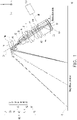
- FIG. 1 is a side schematic diagram of a projection device according to an embodiment of the disclosure.
- FIG. 2 is an enlarged side schematic diagram of an imaging system of the projection device of FIG. 1 .
- FIG. 2 omits a projection surface PS of an imaging system IMS of FIG. 1 .
- a direction z is, for example, a direction perpendicular to the projection surface PS
- a direction y is, for example, a direction parallel to the projection surface PS
- a direction x is, for example, a direction parallel to the projection surface PS and perpendicular to the direction y.
- the projection device 100 includes an illumination system ILS and the imaging system IMS.
- the illumination system ILS is configured to provide an illumination beam ILB.
- the imaging system IMS is configured on a transmission path of the illumination beam ILB.
- the imaging system IMS includes a light valve LV, the projection lens PL, and the projection surface PS.
- the projection lens PL has a reduction side and a magnification side.
- the light valve LV is configured on the reduction side of the projection lens PL.
- the projection surface PS is configured on the magnification side of the projection lens PL.
- a light receiving surface LVa of the light valve LV is configured to receive the illumination beam ILB provided by the illumination system ILS, and the light valve LV is configured to convert the illumination beam ILB into an image beam IMB.
- the projection lens PL is configured on a transmission path of the image beam IMB and is configured to image the image beam IMB from the light valve LV on the projection surface PS located on the magnification side.
- the projection device 100 is an oblique projection device.
- the included angle ⁇ between the projection surface PS and the light receiving surface LVa of the light valve LV satisfies: 0° ⁇ ⁇ ⁇ 90°.
- the included angle ⁇ may satisfy: 25° ⁇ ⁇ ⁇ 90°, but the disclosure is not limited thereto.
- the projection surface PS generally refers to an object surface on which a projection image may be formed.
- the projection surface PS may be a desktop.
- the disclosure is not limited thereto.
- the projection surface PS may also be the ground, a wall, a screen, etc.
- the light valve LV may be a reflective optical modulator, such as a digital micro-mirror device and a liquid-crystal-on-silicon panel (LCOS panel).
- the disclosure is not limited thereto.
- the light valve LV may also be a transmissive optical modulator, such as a transparent liquid crystal panel, an electro-optical modulator, a magneto-optical modulator, and an acousto-optical modulator (AOM).
- AOM acousto-optical modulator
- the imaging system IMS may also optionally include a light combining element PR.
- the illumination system ILS transmits the illumination beam ILB to the light combining element PR.
- the illumination beam ILB is transmitted to the light valve LV via the light combining element PR.
- the light valve LV reflects the illumination beam ILB into the image beam IMB.
- the image beam IMB is transmitted to the projection lens PL via the light combining element PR.
- the light combining element PR may be a total internal reflection prism (TIR prism).
- TIR prism total internal reflection prism
- the light combining element PR may also be a beam splitter, a polarizer beam splitter, a field lens, or other optical elements, depending on the light splitting or light guiding design required by the projection device 100, which is not limited by the disclosure.
- the imaging system IMS may also optionally include a protection cap CG, which is disposed on the light receiving surface LVa of the light valve LV and is located between the light valve LV and the light combining element PR.
- the protection cap CG is configured to protect the light valve LV.
- the material of the protection cap CG is, for example, glass, but the disclosure is not limited thereto.
- the imaging system IMS may also optionally include an actuator AC.
- the actuator AC may have a flat glass and adopt a oscillation technology for the flat glass to quickly oscillate back and forth, and is configured to improve the quality of the projection image of the projection device 100.
- the light valve LV and the projection lens PL may be a telecentric system to reduce the influence of the optical elements (for example, the light combining element PR, the actuator AC, etc.) configured between the light valve LV and the projection lens PL on an optical path of the image beam IMB, but the disclosure is not limited thereto.
- the optical elements for example, the light combining element PR, the actuator AC, etc.
- the projection lens PL includes a lens group LG and a convex mirror M.
- the lens group LG is configured on an optical path between the magnification side and the reduction side.
- the convex mirror M is configured on an optical path between the lens group LG and the magnification side.
- the convex mirror M has a reflective surface Ma.
- the reflective surface Ma is convex.
- the refractive power of the convex mirror M is negative.
- the reflective surface Ma of the mirror M may be aspherical, but the disclosure is not limited thereto.
- the lens group LG includes a first lens element L1, a second lens element L2, a third lens element L3, a fourth lens element L4, a fifth lens element L5, a sixth lens element L6, and a seventh lens element L7 sequentially arranged from the magnification side to the reduction side.
- the refractive power of the overall lens group LG is negative.
- the refractive powers of the first lens element L1, the second lens element L2, the third lens element L3, the fourth lens element L4, the fifth lens element L5, the sixth lens element L6, and the seventh lens element L7 are respectively negative, negative, positive, positive, negative, positive, and positive.
- the first lens element L1 has a first surface L11 (marked in FIG.
- the second lens element L2 has a first surface L21 (marked in FIG. 2 ) facing the convex mirror M and a second surface L22 (marked in FIG. 2 ) facing the light valve LV.
- the third lens element L3 has a first surface L31 (marked in FIG. 2 ) facing the convex mirror M and a second surface L32 (marked in FIG. 2 ) facing the light valve LV.
- the fourth lens element L4 has a first surface L41 (marked in FIG. 2 ) facing the convex mirror M and a second surface L42 (marked in FIG. 2 ) facing the light valve LV.
- the fifth lens element L5 has a first surface L51 (marked in FIG. 2 ) facing the convex mirror M and a second surface L52 (marked in FIG. 2 ) facing the light valve LV.
- the sixth lens element L6 has a first surface L61 (marked in FIG. 2 ) facing the convex mirror M and a second surface L62 (marked in FIG. 2 ) facing the light valve LV.
- the seventh lens element L7 has a first surface L71 (marked in FIG. 2 ) facing the convex mirror M and a second surface L72 (marked in FIG. 2 ) facing the light valve LV.
- the projection lens PL further includes an aperture stop AS, which is configured between the first lens element L1 and the second lens element L2.
- At least one of the third lens element L3 and the fourth lens element L4 is a freeform surface lens element. In this way, the projection lens PL can reduce the phenomenon of trapezoidal distortion.
- the third lens element L3 may be a freeform surface lens element.
- the first surface L31 of the third lens element L3 facing the convex mirror M may be a freeform surface.
- the freeform surface may also be designed on the second surface L32 of the third lens element L3.
- the fourth lens element L4 may also be a freeform surface lens element.
- the first surface L41 of the fourth lens element L4 facing the convex mirror M may be a freeform surface.
- the freeform surface may also be designed on the second surface L42 of the fourth lens element L4.
- the third lens element L3 and the fourth lens element L4 are both freeform surface lens elements.
- the disclosure is not limited thereto.
- the third lens element L3 may be a freeform surface lens element, and the fourth lens element L4 may not be a freeform surface lens element.
- the fourth lens element L4 may be a freeform surface lens element, and the third lens element L3 may not be a freeform surface lens element.
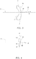
- FIG. 3 is an enlarged side schematic diagram of the first lens element of FIG. 2 . Please refer to FIG. 2 and FIG. 3 .
- one of the first surface L11 and the second surface L12 of the first lens element L1 intersects with an optical axis O of the lens group LG at a first intersection point C11.
- a first tangent plane P11 passes through the first intersection point C11 and is tangent to one of the first surface L11 and the second surface L12 of the first lens element L1.
- FIG. 4 is an enlarged side schematic diagram of the second lens element of FIG. 2 . Please refer to FIG. 2 and FIG. 4 .
- One of the first surface L21 and the second surface L22 of the second lens element L2 intersects with the optical axis O of the lens group LG at a second intersection point C21.
- a second tangent plane P21 passes through the second intersection point C21 and is tangent to one of the first surface L21 and the second surface L22 of the second lens element L2.
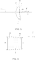
- FIG. 5 is an enlarged side schematic diagram of the fourth lens element of FIG. 2 . Please refer to FIG. 2 and FIG. 5 .
- One of the first surface L41 and the second surface L42 of the fourth lens element L4 intersects with the optical axis O of the lens group LG at a third intersection point C41.
- a third tangent plane P41 passes through the third intersection point C41 and is tangent to one of the first surface L41 and the second surface L42 of the fourth lens element L4.
- At least two of the included angle ⁇ , the included angle ⁇ , and the included angle ⁇ are not 0°, one of the at least two is a positive angle, the other one of the at least two is a negative angle, and the absolute values of the positive angle and the negative angle are respectively greater than 0° and less than or equal to 20°.
- At least two of a surface of the first lens element L1, a surface of the second lens element L2, and a surface of the fourth lens element L4 are inclined relative to the optical axis O of the lens group LG, the inclination directions of the at least two are opposite, the absolute values of the inclination angles of the at least two are greater than 0° and less than or equal to 20°.
- the projection lens PL can further reduce the phenomenon of trapezoidal distortion.
- a surface of the first lens element L1 and a surface of the second lens element L2 are inclined relative to the optical axis O, the inclination directions of the surface of the first lens element L1 and the surface of the second lens element L2 are opposite, and the absolute values of the inclination angles of the surface of the first lens element L1 and the surface of the second lens element L2 are greater than 0° and less than or equal to 20°.
- the first normal vector N11 of the first tangent plane P11 is inclined relative to the optical axis O of the lens group LG, that is, the first surface L11 of the first lens element L1 is inclined relative to the optical axis O.
- the first surface L11 of the first lens element L1 is inclined away from the convex mirror M, so that the first normal vector N11 points above the optical axis O and the inclination angle (that is, the included angle ⁇ ) of the first surface L11 of the first lens element L1 is a positive angle, where
- FIG. 2 and FIG. 4 Please refer to FIG. 2 and FIG. 4 .
- the second normal vector N21 of the second tangent plane P21 is inclined relative to the optical axis O of the lens group LG, that is, the first surface L21 of the second lens element L2 is inclined relative to the optical axis O.
- the first surface L21 of the second lens element L2 is inclined toward the convex mirror M, so that the second normal vector N21 points below the optical axis O and the inclination angle (that is, the included angle ⁇ ) of the first surface L21 of the second lens element L2 is a negative angle, where
- a surface of the fourth lens element L4 and a surface of the second lens element L2 are inclined relative to the optical axis O, the inclination directions of the surface of the fourth lens element L4 and the surface of the second lens element L2 are opposite, and the absolute values of the inclination angles of the surface of the fourth lens element L4 and the surface of the second lens element L2 are greater than 0° and less than or equal to 20°.
- the third normal vector N41 of the third tangent plane P41 is inclined relative to the optical axis O of the lens group LG, that is, the first surface L41 of the fourth lens element L4 is inclined relative to the optical axis O.
- the first surface L41 of the fourth lens element L4 is inclined away from the convex mirror M, so that the third normal vector N41 points above the optical axis O and the inclination angle (that is, the included angle ⁇ ) of the first surface L41 of the fourth lens element L4 is a positive angle, where
- FIG. 2 and FIG. 4 Please refer to FIG. 2 and FIG. 4 .
- the first surface L21 of the second lens element L2 is inclined relative to the optical axis O.
- the first surface L21 of the second lens element L2 is inclined toward the convex mirror M, so that the second normal vector N21 points below the optical axis O and the inclination angle (that is, the included angle ⁇ ) of the first surface L21 of the second lens element L2 is a negative angle, where
- the light receiving surface LVa of the light valve LV is configured to receive the illumination beam ILB, and the illumination beam ILB forms an illumination range ILR (marked in FIG. 2 ) on the light receiving surface LVa of the light valve LV.
- the projection device 10 of the embodiment adopts an offset design, so that a distance D between the first surface L11 of the first lens element L1 and the reflective surface Ma of the convex mirror M on the optical axis O may be shortened.
- configuring the aperture stop AS as close as possible to the first lens element L1 also helps to shorten the distance D.
- the image beam IMB may be easily reflected back to the projection lens PL by the plane mirror to cause interference.
- the distance between the plane mirror and the first surface L11 of the first lens element L1 on the optical axis O must be increased, such that a length L of the projection lens PL cannot be reduced.
- the projection device 100 of the embodiment uses the convex mirror M to deflect the image beam IMB to the projection surface PS.
- the convex mirror M has a negative refractive power.
- the image beam IMB is not easily reflected back to the lens group LG to cause interference after being reflected by the convex mirror M.
- the distance D between the convex mirror M and the first surface L11 of the first lens element L1 on the optical axis O may be reduced, thereby reducing the length L of the projection lens PL.
- the length L of the projection lens PL refers to the distance between the reflective surface Ma of the convex mirror M and the second surface L72 of the seventh lens element L7 on the optical axis O.
- the length L of the projection lens PL may be less than 42 mm.
- the reflective surface Ma of the convex mirror M has a curvature radius R.
- the curvature radius R may satisfy: 50 mm ⁇ R ⁇ 110 mm.
- the size of the convex mirror M may be reduced to reduce the space occupied by the projection lens PL.
- an optical effective diameter M1 of the convex mirror M and the height of the illumination range ILR in a direction perpendicular to the optical axis O may satisfy: 2 ⁇ (M1 / the height of ILR in the direction perpendicular to the optical axis O) ⁇ 3.
- the distance D between the convex mirror M and the first surface L11 of the first lens element L1 on the optical axis O is too large, the speckle on the reflective surface Ma of the convex mirror M will be too large, which is not conducive to reducing the space occupied by the projection lens PL. Conversely, if the distance D between the convex mirror M and the first surface L11 of the first lens element L1 on the optical axis O is too small, the image beam IMB will be easily reflected back to the projection lens PL by the convex mirror M to cause interference.
- the distance D between the first surface L11 of the first lens element L1 and the reflective surface Ma of the convex mirror M on the optical axis O may satisfy: 1.5 mm ⁇ D ⁇ 5 mm.
- a maximum height H of the projection lens PL may be less than 13.5 mm.
- An edge of a lens element with the largest diameter (for example, an edge L7e of the seventh lens element L7) in the lens group LG and an end point Mt of the convex mirror M are respectively located on two sides of the optical axis O.
- the maximum height H of the projection lens PL may refer to the distance between the edge of the lens element with the largest diameter (for example: the edge L7e of the seventh lens element L7) in the lens group LG and the end point Mt of the convex mirror M in the direction perpendicular to the optical axis O.
- FIG. 6 schematically depicts an image formed by an image beam on a projection surface according to an embodiment of the disclosure.
- the light receiving surface LVa of the light valve LV is configured to receive the illumination beam ILB to convert the illumination beam ILB into the image beam IMB.
- the image beam IMB sequentially passes through the lens group LG and is reflected by the convex mirror M to the projection surface PS.
- the image beam IMB forms an image IM on the projection surface PS (that is, a paper surface of FIG. 6 ).
- a first edge ray IMB1 and a second edge ray IMB2 of two opposite sides of the image IM are substantially parallel to each other and respectively have a length A and a length B in the direction x.
- trapezoidal distortion of the image IM is less than 0.5%.
- Table 1 lists various parameters of the imaging system IMS according to an embodiment of the disclosure. Please refer to FIG. 2 and Table 1.
- the spacing in Table 1 refers to the straight line distance between two adjacent surfaces on the optical axis O.
- the spacing of the surface Ma is the straight line distance between the surface Ma and the surface L11 on the optical axis O.
- the curvature radius, the spacing, the refractive index, and the Abbe number corresponding to each surface/element in Table 1 please refer to the corresponding values of each curvature radius, spacing, refractive index, and Abbe number in the same column.
- Ma is the reflective surface of the mirror M
- L11 is the first surface of the first lens element L1 facing the convex mirror M
- L12 is the second surface of the first lens element L1 facing the light valve LV
- ASa is the light passing cross section of the aperture stop AS
- L21 is the first surface of the second lens element L2 facing the convex mirror M
- L22 is the second surface of the second lens element L2 facing the light valve LV
- L31 is the first surface of the third lens element L3 facing the convex mirror M
- L32 is the second surface of the third lens element L3 facing the light valve LV
- L41 is the first surface of the fourth lens element L4 facing the convex mirror M
- L42 is the second surface of the fourth lens element L4 facing the light valve LV
- L51 is the first surface of the fifth lens element L5 facing the convex mirror M
- L61 is the first surface of the sixth lens element L6 facing the convex mirror M
- L62 is the second surface of the sixth lens element L
- the reflective surface Ma of the convex mirror M may be aspherical.
- the first lens element L1 may be aspherical.
- the first surface L11 facing the convex mirror M and the second surface L12 facing the light valve LV of the first lens element L1 may both be aspherical.
- the second lens element L2 may be spherical.
- the first surface L21 facing the convex mirror M and the second surface L22 facing the light valve LV of the second lens element L2 may both be spherical.
- the third lens element L3 may be a freeform surface lens element.
- the first surface L31 facing the convex mirror M of the third lens element L3 may be a freeform surface
- the second surface L32 facing the light valve LV of the third lens element L3 may be aspherical.
- the fourth lens element L4 may be a freeform surface lens element.
- the first surface L41 facing the convex mirror M of the fourth lens element L4 may be a freeform surface
- the second surface L42 facing the light valve LV of the fourth lens element L4 may be aspherical.
- the fifth lens element L5 may be spherical.
- the first surface L51 facing the convex mirror M and the second surface L52 facing the light valve LV of the fifth lens element L5 may both be spherical.
- the sixth lens element L6 may be spherical.
- the first surface L61 facing the convex mirror M and the second surface L62 facing the light valve LV of the sixth lens element L6 may both be spherical.
- the second surface L52 of the fifth lens element L5 and the first surface L61 of the sixth lens element L6 may be bonded together, so that the fifth lens element L5 and the sixth lens element L6 form a double cemented lens.
- the refractive power of the double cemented lens formed by the fifth lens element L5 and the sixth lens element L6 may be negative.
- the seventh lens element L7 may be aspherical.
- the first surface L71 facing the convex mirror M and the second surface L72 facing the light valve LV of the seventh lens element L7 may both be aspherical.
- the reflective surface Ma of the mirror M, the first surface L11 facing the convex mirror M of the first lens element L1, the second surface L12 facing the light valve LV of the first lens element L1, the second surface L32 facing the light valve LV of the third lens element L3, and the second surface L42 facing the light valve LV of the fourth lens element L4 are even-order aspheric surfaces.
- Z is the offset (sag) in the direction of the optical axis O;
- c is the reciprocal of the radius of the osculating sphere, which is the reciprocal of the curvature radius (such as the curvature radius in Table 1) close to the optical axis O;
- k is the conic constant;
- r is the height of the aspheric surface, that is, the height from the center of the convex mirror/lens element to the edge of the convex mirror/lens element; and
- a 2 , A 4 , A 6 , A 8 , A 10 , A 12 , A 14 ... are aspheric coefficients.
- Table 2 lists the quadric surface coefficients and the aspheric coefficients of the reflective surface Ma of the mirror M, the first surface L11 facing the convex mirror M of the first lens element L1, the second surface L12 facing the light valve LV of the first lens element L1, the second surface L32 facing the light valve LV of the third lens element L3, and the second surface L42 facing the light valve LV of the fourth lens element L4.
- the first surface L31 of the third lens element L3 and the first surface L41 of the fourth lens element L4 are freeform surfaces.
- Table 3 lists the coefficients of the monomials x m y n of the first surface L31 of the third lens element L3 and the first surface L41 of the fourth lens element L4.
- the first surface L11 of the first lens element L1, the first surface L21 of the second lens element L2, and the first surface L41 of the fourth lens element L4 are inclined relative to the optical axis O of the lens group LG.
- Table 4 lists the inclination angles (that is, the included angle ⁇ , the included angle ⁇ , and the included angle ⁇ ) of the first surface L11 of the first lens element L1, the first surface L21 of the second lens element L2, and the first surface L41 of the fourth lens element L4.
- the first lens element L1 may be a convex-concave lens element with a concave surface facing the reduction side
- the second lens element L2 may be a convex-concave lens element with a convex surface facing the reduction side
- the third lens element L3 may be a concave-convex lens element with a concave surface facing the reduction side
- the fourth lens element L4 may be a concave-convex lens element with a convex surface facing the reduction side
- the fifth lens element L5 may be a biconcave lens element
- the sixth lens element L6 may be a biconvex lens element
- the seventh lens element L7 may be a concave-convex lens element with a convex surface facing the reduction side .
- the materials of the first lens element L1, the second lens element L2, the third lens element L3, the fourth lens element L4, the fifth lens element L5, the sixth lens element L6, and the seventh lens element L7 may respectively be plastic, glass, glass, glass, glass, glass, and glass, but the disclosure is not limited thereto.
- the projection lens PL may be a fixed-focus lens, which has a simple structure, is easy to assemble, and has a short manufacturing time compared with a zoom lens.
- the projection lens PL has a large half field of view.
- the projection lens PL has a small throw ratio and can project a wide projection image within a short projection distance.
- the half field of view of the projection lens PL may be greater than 45°, but the disclosure is not limited thereto.
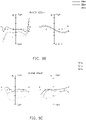
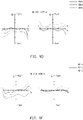
- FIG. 7 is a modulation transfer function diagram of the projection lens of FIG. 2 .
- FIG. 7 is the modulation transfer function (MTF) diagram of the projection lens PL at different image heights, where the horizontal axis is the focus shift, the vertical axis is the modulus of the optical transfer function, T represents the curve in the meridian direction, S represents the curve in the sagittal direction, and the values marked next to "TS" represent the image heights.
- MTF modulation transfer function
- FIG. 8 is a lateral chromatic aberration diagram of the projection lens of FIG. 2 , which is a simulation data diagram of light with wavelengths of 462 nm, 525 nm, and 615 nm, where the ordinate is the normalized image height.
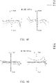
- FIG. 9A to FIG. 9I are ray fan plots of the projection lens of FIG. 2 .
- FIG. 9A to FIG. 9I are the ray fan plots of the projection lens PL at different image heights, where the maximum scale and the minimum scale of the Ex axis and the Ey axis are respectively +10 ⁇ m and -10 ⁇ m, and the Px axis and the Py axis have been normalized, so the maximum scale and the minimum scale of the Px and Py axes are respectively 1 and -1.
- FIG. 7 , FIG. 8, and FIG. 9A to FIG. 9I are all within the standard range. It can be verified that the projection lens PL of the embodiment can achieve a good imaging effect.
- FIG. 10 schematically depicts an image on a projection surface of the projection device of FIG. 1 .
- FIG. 11 schematically depicts an image on a projection surface of a projection device of a comparative example.
- the projection device (not shown) corresponding to the comparative example of FIG. 11 is similar to the projection device 100 of an embodiment of the disclosure corresponding to FIG. 10 . The difference between the two is that: in the projection device corresponding to the comparative example of FIG.
- a first surface (referring to a surface of a third lens element facing the convex mirror) of the third lens element (referring to the third lens element sequentially arranged from the magnification side to the reduction side of the projection lens) and a first surface (referring to a surface of a fourth lens element facing the convex mirror) of the fourth lens element (referring to the fourth lens element sequentially arranged from the magnification side to the reduction side of the projection lens) are not freeform surfaces, and a first surface (referring to a surface of a first lens element facing the convex mirror) of the first lens element (referring to the first lens element sequentially arranged from the magnification side to the reduction side of the projection lens), a first surface (referring to a surface of a second lens element facing the convex mirror) of the second lens element (referring to the second lens element sequentially arranged from the magnification side to the reduction side of the projection lens), and the first surface (referring to the surface of the fourth lens element facing the convex mirror) of the fourth lens element (referring
- the projection device and the imaging system thereof of an embodiment of the disclosure include the projection lens having the magnification side and the reduction side.
- the projection lens includes the lens group configured on the optical path between the magnification side and the reduction side and the convex mirror configured on the optical path between the lens group and the magnification side.
- the lens group includes the first lens element, the second lens element, the third lens element, the fourth lens element, the fifth lens element, the sixth lens element, and the seventh lens element sequentially arranged from the magnification side to the reduction side.
- the refractive powers of the first lens element, the second lens element, the third lens element, the fourth lens element, the fifth lens element, the sixth lens element, and the seventh lens element are respectively negative, negative, positive, positive, negative, positive, and positive.
- at least one of the third lens element and the fourth lens element is a freeform surface lens element. In this way, the projection lens itself can reduce the phenomenon of trapezoidal distortion without using software to correct trapezoidal distortion and losing the brightness and resolution of the projection image.
- At least two of a surface of the first lens element, a surface of the second lens element, and a surface of the fourth lens element are inclined relative to the optical axis of the lens group, the inclination directions of the at least two are opposite, and the absolute values of the inclination angles of the at least two are greater than 0° and less than or equal to 20°. In this way, the phenomenon of trapezoidal distortion can be further reduced.
- the term "the invention”, “the present invention” or the like does not necessarily limit the claim scope to a specific embodiment, and the reference to particularly preferred exemplary embodiments of the invention does not imply a limitation on the invention, and no such limitation is to be inferred.
- the invention is limited only by the scope of the appended claims. Moreover, these claims may refer to use "first”, “second”, etc. following with noun or element. Such terms should be understood as a nomenclature and should not be construed as giving the limitation on the number of the elements modified by such nomenclature unless specific number has been given.
- the abstract of the disclosure is provided to comply with the rules requiring an abstract, which will allow a searcher to quickly ascertain the subject matter of the technical disclosure of any patent issued from this disclosure.
Abstract
An imaging system, including a light valve, a projection surface, and a projection lens, is provided. The projection lens has a reduction side and a magnification side, and includes a lens group and a convex mirror. The light valve is configured on the reduction side. The projection surface is configured on the magnification side. There is an included angle between the projection surface and a light receiving surface. The lens group is configured on an optical path between the magnification side and the reduction side, and includes first to seventh lens elements sequentially arranged from the magnification side to the reduction side. The refractive powers of the first to seventh lens elements are respectively negative, negative, positive, positive, negative, positive, and positive. The convex mirror is configured on an optical path between the lens group and the magnification side. A projection device, including the imaging system, is also provided.
Description
- This application claims the priority of
U.S. Provisional Application No. 63/115,597, filed on November 18, 2020 China Application No. 202110811083.2, filed on July 19, 2021 - The disclosure relates to an optical system and an optical device, and particularly relates to an imaging system and a projection device.
- The projector has been widely applied to home appliances, office equipment, game consoles, etc. The requirements for the projector are gradually developing toward lightness, thinness, shortness, and smallness. For example, compared to the projector using the traditional light source, the pocket projector using the light emitting diode is small in size and light in weight, which can reduce space requirements and is easy to carry.
- In practical applications, in order to reduce the usage space of the projector, the mechanism of the projector needs to be modified to change the traditional vertical projection to the oblique projection, so that a projection image may be deflected through a mirror, and the deflected projection image may be projected onto a projection surface (for example, a desktop, the ground, a wall, a screen, etc.) according to requirements. In the oblique projection architecture, the reference ray of emergent light of the projector cannot be perpendicular to the projection surface, that is, oblique incidence, which causes trapezoidal distortion of the projection image. Traditionally, in order to reduce the trapezoidal distortion, software may be used to crop a distorted region of the projection image, thereby achieving a distortion-free situation. However, such software correction manner results in reduction in resolution and loss of brightness. In addition, another manner to reduce trapezoidal distortion is hardware correction, that is, to move the projection lens. However, such method causes the projector to become larger in size.
- The information disclosed in this Background section is only for enhancement of understanding of the background of the described technology and therefore it may contain information that does not form the prior art that is already known to a person of ordinary skill in the art. Further, the information disclosed in the Background section does not mean that one or more problems to be resolved by one or more embodiments of the invention was acknowledged by a person of ordinary skill in the art.
- It is an object of the disclosure to provide an imaging system and/or a projection device, which can reduce the phenomenon of trapezoidal distortion.
- The other objectives and advantages of the disclosure may be further understood from the technical features disclosed in the disclosure.
- The object is solved by the features of the independent claims. Preferred embodiments are given in the dependent claims.
- In order to achieve one, a part, or all of the above objectives or other objectives, an embodiment of the disclosure provides an imaging system. The imaging system of the disclosure includes a light valve, a projection surface, and a projection lens. The light valve is configured to provide an image beam. There is an included angle between the projection surface and a light receiving surface of the light valve. The projection lens is configured on a transmission path of the image beam and has a reduction side and a magnification side. The light valve is configured on the reduction side of the projection lens. The projection surface is configured on the magnification side of the projection lens. The projection lens includes a lens group and a convex mirror. The lens group is configured on an optical path between the magnification side and the reduction side, and includes a first lens element, a second lens element, a third lens element, a fourth lens element, a fifth lens element, a sixth lens element, and a seventh lens element sequentially arranged from the magnification side to the reduction side. The refractive powers of the first lens element, the second lens element, the third lens element, the fourth lens element, the fifth lens element, the sixth lens element, and the seventh lens element are respectively negative, negative, positive, positive, negative, positive, and positive. At least one of the third lens element and the fourth lens element is a freeform surface lens element. The convex mirror is configured on an optical path between the lens group and the magnification side. Each of the first lens element, the second lens element, the third lens element, the fourth lens element, the fifth lens element, the sixth lens element, and the seventh lens element has a first surface facing the convex mirror and a second surface facing the light valve.
- In order to achieve one, a part, or all of the above objectives or other objectives, another embodiment of the disclosure provides a projection device. The projection device of the disclosure includes the imaging system and an illumination system. The illumination system is configured to provide an illumination beam. The imaging system is configured on a transmission path of the illumination beam. The light receiving surface of the light valve of the imaging system is configured to receive the illumination beam, and the light valve of the imaging system is configured to convert the illumination beam into the image beam.
- The above mentioned aspects could be further combined with one or more of the following optional features.
- In one or more of the embodiments, the first surface of the third lens element may be a freeform surface.
- In one or more of the embodiments, the first surface of the fourth lens element may be a freeform surface.
- In one or more of the embodiments, one of the first surface and the second surface of the first lens element may intersect with an optical axis of the lens group at a first intersection point.
- A first tangent plane may be tangent to the one of the first surface and the second surface of the first lens element through the first intersection point.
- A first normal vector of the first tangent plane may be inclined relative to the optical axis of the lens group.
- In one or more of the embodiments, one of the first surface and the second surface of the second lens element may intersect with an optical axis of the lens group at a second intersection point.
- A second tangent plane may be tangent to the one of the first surface and the second surface of the second lens element through the second intersection point.
- A second normal vector of the second tangent plane may be inclined relative to the optical axis of the lens group.
- In one or more of the embodiments, one of the first surface and the second surface of the fourth lens element may intersect with an optical axis of the lens group at a third intersection point.
- A third tangent plane may be tangent to the one of the first surface and the second surface of the fourth lens element through the third intersection point.
- A third normal vector of the third tangent plane may be inclined relative to the optical axis of the lens group.
- In one or more of the embodiments, the light receiving surface of the light valve may be configured to receive an illumination beam.
- In one or more of the embodiments, the illumination beam may form an illumination range on the light receiving surface of the light valve.
- In one or more of the embodiments, there may be a fourth intersection point between the light receiving surface of the light valve and an optical axis of the lens group.
- There may be an offset between a center of the illumination range and the fourth intersection point.
- In one or more of the embodiments, there may be a distance D between the first surface of the first lens element and a reflective surface of the convex mirror on an optical axis of the lens group, preferably 1.5 mm < D < 5 mm.
- In one or more of the embodiments, a reflective surface of the convex mirror may have a curvature radius R, preferably 50 mm < R < 110 mm.
- In one or more of the embodiments, the projection lens may have a maximum height H in a direction perpendicular to an optical axis of the lens group, where H < 13.5 mm.
- In one or more of the embodiments, an angle of the included angle may be θ, preferably 25° < θ < 90°.
- In one or more of the embodiments, the light receiving surface of the light valve may be configured to receive an illumination beam to convert the illumination beam into the image beam; the image beam sequentially passes through the lens group and is reflected to the projection surface by the convex mirror.
- In one or more of the embodiments, the image beam may form an image on the projection surface.
- In one or more of the embodiments, two opposite sides of the image may be substantially parallel to each other and respectively have a length A and a length B in a direction.
- In one or more of the embodiments, the image may have a maximum width W in the direction, preferably [(B-A)/W] • 100% = T and |T| < 0.5%.
- In one or more of the embodiments, the projection lens may further comprise an aperture stop.
- In one or more of the embodiments, the aperture stop may be disposed between the first lens element and the second lens element.
- Based on the above, in the projection device and the imaging system thereof of an embodiment of the disclosure, at least one of the third lens element and the fourth lens element of the projection lens is the freeform surface lens element. In this way, the projection lens itself can reduce the phenomenon of trapezoidal distortion without using software to correct trapezoidal distortion and losing the brightness and resolution of the projection image.
- Other objectives, features and advantages of the invention will be further understood from the further technological features disclosed by the embodiments of the invention wherein there are shown and described preferred embodiments of this invention, simply by way of illustration of modes best suited to carry out the invention.
- The accompanying drawings are included to provide a further understanding of the invention, and are incorporated in and constitute a part of this specification. The drawings illustrate embodiments of the invention and, together with the description, serve to explain the principles of the invention.
-
FIG. 1 is a side schematic diagram of a projection device of an embodiment of the disclosure. -
FIG.2 an enlarged side schematic diagram of an imaging system of the projection device ofFIG. 1 -
FIG. 3 is an enlarged side schematic diagram of a first lens element ofFIG. 2 . -
FIG. 4 is an enlarged side schematic diagram of a second lens element ofFIG. 2 . -
FIG. 5 is an enlarged side schematic diagram of a fourth lens element ofFIG. 2 . -
FIG. 6 schematically depicts an image formed by an image beam on a projection surface according to an embodiment of the disclosure. -
FIG. 7 is a modulation transfer function diagram of the projection lens ofFIG. 2 . -
FIG. 8 is a lateral chromatic aberration diagram of the projection lens ofFIG. 2 . -
FIG. 9A to FIG. 9I are ray fan plots of the projection lens ofFIG. 2 . -
FIG. 10 schematically depicts an image on a projection surface of the projection device ofFIG.1 . -
FIG. 11 schematically depicts an image on a projection surface of a projection device of a comparative example. - In the following detailed description of the preferred embodiments, reference is made to the accompanying drawings which form a part hereof, and in which are shown by way of illustration specific embodiments in which the invention may be practiced. In this regard, directional terminology, such as "top," "bottom," "front," "back," etc., is used with reference to the orientation of the Figure(s) being described. The components of the invention can be positioned in a number of different orientations. As such, the directional terminology is used for purposes of illustration and is in no way limiting. On the other hand, the drawings are only schematic and the sizes of components may be exaggerated for clarity. It is to be understood that other embodiments may be utilized and structural changes may be made without departing from the scope of the invention. Also, it is to be understood that the phraseology and terminology used herein are for the purpose of description and should not be regarded as limiting. The use of "including," "comprising," or "having" and variations thereof herein is meant to encompass the items listed thereafter and equivalents thereof as well as additional items. Unless limited otherwise, the terms "connected," "coupled," and "mounted" and variations thereof herein are used broadly and encompass direct and indirect connections, couplings, and mountings. Similarly, the terms "facing," "faces" and variations thereof herein are used broadly and encompass direct and indirect facing, and "adjacent to" and variations thereof herein are used broadly and encompass directly and indirectly "adjacent to". Therefore, the description of "A" component facing "B" component herein may contain the situations that "A" component directly faces "B" component or one or more additional components are between "A" component and "B" component. Also, the description of "A" component "adjacent to" "B" component herein may contain the situations that "A" component is directly "adjacent to" "B" component or one or more additional components are between "A" component and "B" component. Accordingly, the drawings and descriptions will be regarded as illustrative in nature and not as restrictive.
- Reference will now be made in detail to the exemplary embodiments of the disclosure, and examples of the exemplary embodiments are illustrated in the accompanying drawings. Whenever possible, the same reference numerals are used in the drawings and the description to indicate the same or similar parts.
-
FIG. 1 is a side schematic diagram of a projection device according to an embodiment of the disclosure.FIG. 2 is an enlarged side schematic diagram of an imaging system of the projection device ofFIG. 1 . In order to clearly illustrate a projection lens PL,FIG. 2 omits a projection surface PS of an imaging system IMS ofFIG. 1 . - Please refer to
FIG. 1 andFIG. 2 . In the figures, a direction z is, for example, a direction perpendicular to the projection surface PS, a direction y is, for example, a direction parallel to the projection surface PS, and a direction x is, for example, a direction parallel to the projection surface PS and perpendicular to the direction y. - Please refer to
FIG. 1 . Theprojection device 100 includes an illumination system ILS and the imaging system IMS. The illumination system ILS is configured to provide an illumination beam ILB. The imaging system IMS is configured on a transmission path of the illumination beam ILB. The imaging system IMS includes a light valve LV, the projection lens PL, and the projection surface PS. The projection lens PL has a reduction side and a magnification side. The light valve LV is configured on the reduction side of the projection lens PL. The projection surface PS is configured on the magnification side of the projection lens PL. A light receiving surface LVa of the light valve LV is configured to receive the illumination beam ILB provided by the illumination system ILS, and the light valve LV is configured to convert the illumination beam ILB into an image beam IMB. The projection lens PL is configured on a transmission path of the image beam IMB and is configured to image the image beam IMB from the light valve LV on the projection surface PS located on the magnification side. In particular, there is an included angle θ between the projection surface PS and the light receiving surface LVa of the light valve LV. In other words, theprojection device 100 is an oblique projection device. - The included angle θ between the projection surface PS and the light receiving surface LVa of the light valve LV satisfies: 0° < θ < 90°. For example, in the embodiment, the included angle θ may satisfy: 25° < θ < 90°, but the disclosure is not limited thereto.
- The projection surface PS generally refers to an object surface on which a projection image may be formed. For example, in the embodiment, the projection surface PS may be a desktop. However, the disclosure is not limited thereto. In other embodiments, the projection surface PS may also be the ground, a wall, a screen, etc.
- In the embodiment, the light valve LV may be a reflective optical modulator, such as a digital micro-mirror device and a liquid-crystal-on-silicon panel (LCOS panel). However, the disclosure is not limited thereto. In other embodiments, the light valve LV may also be a transmissive optical modulator, such as a transparent liquid crystal panel, an electro-optical modulator, a magneto-optical modulator, and an acousto-optical modulator (AOM).
- In the embodiment, the imaging system IMS may also optionally include a light combining element PR. The illumination system ILS transmits the illumination beam ILB to the light combining element PR. The illumination beam ILB is transmitted to the light valve LV via the light combining element PR. The light valve LV reflects the illumination beam ILB into the image beam IMB. The image beam IMB is transmitted to the projection lens PL via the light combining element PR. For example, in the embodiment, the light combining element PR may be a total internal reflection prism (TIR prism). However, the disclosure is not limited thereto. In other embodiments, the light combining element PR may also be a beam splitter, a polarizer beam splitter, a field lens, or other optical elements, depending on the light splitting or light guiding design required by the
projection device 100, which is not limited by the disclosure. - In the embodiment, the imaging system IMS may also optionally include a protection cap CG, which is disposed on the light receiving surface LVa of the light valve LV and is located between the light valve LV and the light combining element PR. The protection cap CG is configured to protect the light valve LV. In the embodiment, the material of the protection cap CG is, for example, glass, but the disclosure is not limited thereto.
- In the embodiment, the imaging system IMS may also optionally include an actuator AC. The actuator AC may have a flat glass and adopt a oscillation technology for the flat glass to quickly oscillate back and forth, and is configured to improve the quality of the projection image of the
projection device 100. - In the embodiment, the light valve LV and the projection lens PL may be a telecentric system to reduce the influence of the optical elements (for example, the light combining element PR, the actuator AC, etc.) configured between the light valve LV and the projection lens PL on an optical path of the image beam IMB, but the disclosure is not limited thereto.
- The projection lens PL includes a lens group LG and a convex mirror M. The lens group LG is configured on an optical path between the magnification side and the reduction side. The convex mirror M is configured on an optical path between the lens group LG and the magnification side. The convex mirror M has a reflective surface Ma. The reflective surface Ma is convex. The refractive power of the convex mirror M is negative. For example, in the embodiment, the reflective surface Ma of the mirror M may be aspherical, but the disclosure is not limited thereto.
- Please refer to
FIG. 1 andFIG. 2 . The lens group LG includes a first lens element L1, a second lens element L2, a third lens element L3, a fourth lens element L4, a fifth lens element L5, a sixth lens element L6, and a seventh lens element L7 sequentially arranged from the magnification side to the reduction side. The refractive power of the overall lens group LG is negative. The refractive powers of the first lens element L1, the second lens element L2, the third lens element L3, the fourth lens element L4, the fifth lens element L5, the sixth lens element L6, and the seventh lens element L7 are respectively negative, negative, positive, positive, negative, positive, and positive. The first lens element L1 has a first surface L11 (marked inFIG. 2 ) facing the convex mirror M and a second surface L12 (marked inFIG. 2 ) facing the light valve LV. The second lens element L2 has a first surface L21 (marked inFIG. 2 ) facing the convex mirror M and a second surface L22 (marked inFIG. 2 ) facing the light valve LV. The third lens element L3 has a first surface L31 (marked inFIG. 2 ) facing the convex mirror M and a second surface L32 (marked inFIG. 2 ) facing the light valve LV. The fourth lens element L4 has a first surface L41 (marked inFIG. 2 ) facing the convex mirror M and a second surface L42 (marked inFIG. 2 ) facing the light valve LV. The fifth lens element L5 has a first surface L51 (marked inFIG. 2 ) facing the convex mirror M and a second surface L52 (marked inFIG. 2 ) facing the light valve LV. The sixth lens element L6 has a first surface L61 (marked inFIG. 2 ) facing the convex mirror M and a second surface L62 (marked inFIG. 2 ) facing the light valve LV. The seventh lens element L7 has a first surface L71 (marked inFIG. 2 ) facing the convex mirror M and a second surface L72 (marked inFIG. 2 ) facing the light valve LV. In the embodiment, the projection lens PL further includes an aperture stop AS, which is configured between the first lens element L1 and the second lens element L2. - It is worth noting that at least one of the third lens element L3 and the fourth lens element L4 is a freeform surface lens element. In this way, the projection lens PL can reduce the phenomenon of trapezoidal distortion.
- In the embodiment, the third lens element L3 may be a freeform surface lens element. For example, in the embodiment, the first surface L31 of the third lens element L3 facing the convex mirror M may be a freeform surface. However, the disclosure is not limited thereto. In other embodiments, the freeform surface may also be designed on the second surface L32 of the third lens element L3.
- In the embodiment, the fourth lens element L4 may also be a freeform surface lens element. For example, in the embodiment, the first surface L41 of the fourth lens element L4 facing the convex mirror M may be a freeform surface. However, the disclosure is not limited thereto. In other embodiments, the freeform surface may also be designed on the second surface L42 of the fourth lens element L4.
- In the embodiment, the third lens element L3 and the fourth lens element L4 are both freeform surface lens elements. However, the disclosure is not limited thereto. In another embodiment, the third lens element L3 may be a freeform surface lens element, and the fourth lens element L4 may not be a freeform surface lens element. In yet another embodiment, the fourth lens element L4 may be a freeform surface lens element, and the third lens element L3 may not be a freeform surface lens element.
-
FIG. 3 is an enlarged side schematic diagram of the first lens element ofFIG. 2 . Please refer toFIG. 2 andFIG. 3 . In the embodiment, one of the first surface L11 and the second surface L12 of the first lens element L1 intersects with an optical axis O of the lens group LG at a first intersection point C11. A first tangent plane P11 passes through the first intersection point C11 and is tangent to one of the first surface L11 and the second surface L12 of the first lens element L1. There is an included angle α between a first normal vector N11 of the first tangent plane P11 and the optical axis O of the lens group LG. -
FIG. 4 is an enlarged side schematic diagram of the second lens element ofFIG. 2 . Please refer toFIG. 2 andFIG. 4 . One of the first surface L21 and the second surface L22 of the second lens element L2 intersects with the optical axis O of the lens group LG at a second intersection point C21. A second tangent plane P21 passes through the second intersection point C21 and is tangent to one of the first surface L21 and the second surface L22 of the second lens element L2. There is an included angle β between a second normal vector N21 of the second tangent plane P21 and the optical axis O of the lens group LG. -
FIG. 5 is an enlarged side schematic diagram of the fourth lens element ofFIG. 2 . Please refer toFIG. 2 andFIG. 5 . One of the first surface L41 and the second surface L42 of the fourth lens element L4 intersects with the optical axis O of the lens group LG at a third intersection point C41. A third tangent plane P41 passes through the third intersection point C41 and is tangent to one of the first surface L41 and the second surface L42 of the fourth lens element L4. There is an included angle γ between a third normal vector N41 of the third tangent plane P41 and the optical axis O of the lens group LG. - Please refer to
FIG. 2 ,FIG. 3 ,FIG. 4 , andFIG. 5 . In the embodiment, at least two of the included angle α, the included angle β, and the included angle γ are not 0°, one of the at least two is a positive angle, the other one of the at least two is a negative angle, and the absolute values of the positive angle and the negative angle are respectively greater than 0° and less than or equal to 20°. In other words, at least two of a surface of the first lens element L1, a surface of the second lens element L2, and a surface of the fourth lens element L4 are inclined relative to the optical axis O of the lens group LG, the inclination directions of the at least two are opposite, the absolute values of the inclination angles of the at least two are greater than 0° and less than or equal to 20°. In this way, the projection lens PL can further reduce the phenomenon of trapezoidal distortion. - Please refer to
FIG. 2 ,FIG. 3, and FIG. 4 . For example, in the embodiment, a surface of the first lens element L1 and a surface of the second lens element L2 are inclined relative to the optical axis O, the inclination directions of the surface of the first lens element L1 and the surface of the second lens element L2 are opposite, and the absolute values of the inclination angles of the surface of the first lens element L1 and the surface of the second lens element L2 are greater than 0° and less than or equal to 20°. - Please refer to
FIG. 2 andFIG. 3 . Specifically, in the embodiment, the first normal vector N11 of the first tangent plane P11 is inclined relative to the optical axis O of the lens group LG, that is, the first surface L11 of the first lens element L1 is inclined relative to the optical axis O. In the embodiment, the first surface L11 of the first lens element L1 is inclined away from the convex mirror M, so that the first normal vector N11 points above the optical axis O and the inclination angle (that is, the included angle α) of the first surface L11 of the first lens element L1 is a positive angle, where |α|≤20°. Please refer toFIG. 2 andFIG. 4 . The second normal vector N21 of the second tangent plane P21 is inclined relative to the optical axis O of the lens group LG, that is, the first surface L21 of the second lens element L2 is inclined relative to the optical axis O. In the embodiment, the first surface L21 of the second lens element L2 is inclined toward the convex mirror M, so that the second normal vector N21 points below the optical axis O and the inclination angle (that is, the included angle β) of the first surface L21 of the second lens element L2 is a negative angle, where |β|≤20°. - Please refer to
FIG. 2 ,FIG. 4 , andFIG. 5 . For example, in the embodiment, a surface of the fourth lens element L4 and a surface of the second lens element L2 are inclined relative to the optical axis O, the inclination directions of the surface of the fourth lens element L4 and the surface of the second lens element L2 are opposite, and the absolute values of the inclination angles of the surface of the fourth lens element L4 and the surface of the second lens element L2 are greater than 0° and less than or equal to 20°. - Please refer to
FIG. 2 andFIG. 5 . Specifically, in the embodiment, the third normal vector N41 of the third tangent plane P41 is inclined relative to the optical axis O of the lens group LG, that is, the first surface L41 of the fourth lens element L4 is inclined relative to the optical axis O. In the embodiment, the first surface L41 of the fourth lens element L4 is inclined away from the convex mirror M, so that the third normal vector N41 points above the optical axis O and the inclination angle (that is, the included angle γ) of the first surface L41 of the fourth lens element L4 is a positive angle, where |γ|≤20°. Please refer toFIG. 2 andFIG. 4 . The first surface L21 of the second lens element L2 is inclined relative to the optical axis O. The first surface L21 of the second lens element L2 is inclined toward the convex mirror M, so that the second normal vector N21 points below the optical axis O and the inclination angle (that is, the included angle β) of the first surface L21 of the second lens element L2 is a negative angle, where |β|≤20°. - Please refer to
FIG. 1 and2 , the light receiving surface LVa of the light valve LV is configured to receive the illumination beam ILB, and the illumination beam ILB forms an illumination range ILR (marked inFIG. 2 ) on the light receiving surface LVa of the light valve LV. In particular, in the embodiment, there is a fourth intersection point CLV (marked inFIG. 2 ) between the light receiving surface LVa of the light valve LV and the optical axis O of the lens group LG, and there is an offset δ (marked inFIG. 2 ) between a center ILRc of the illumination range ILR and the fourth intersection point CLV (marked inFIG. 2 ). In other words, the projection device 10 of the embodiment adopts an offset design, so that a distance D between the first surface L11 of the first lens element L1 and the reflective surface Ma of the convex mirror M on the optical axis O may be shortened. In addition, configuring the aperture stop AS as close as possible to the first lens element L1 (for example, configuring the aperture stop AS between the first lens element L1 and the second lens element L2) also helps to shorten the distance D. - Please refer to
FIG. 1 andFIG. 2 . If a plane mirror is used to replace the convex mirror M to deflect the image beam IMB, the image beam IMB may be easily reflected back to the projection lens PL by the plane mirror to cause interference. In order to avoid interference, the distance between the plane mirror and the first surface L11 of the first lens element L1 on the optical axis O must be increased, such that a length L of the projection lens PL cannot be reduced. Theprojection device 100 of the embodiment uses the convex mirror M to deflect the image beam IMB to the projection surface PS. The convex mirror M has a negative refractive power. The image beam IMB is not easily reflected back to the lens group LG to cause interference after being reflected by the convex mirror M. As such, the distance D between the convex mirror M and the first surface L11 of the first lens element L1 on the optical axis O may be reduced, thereby reducing the length L of the projection lens PL. The length L of the projection lens PL refers to the distance between the reflective surface Ma of the convex mirror M and the second surface L72 of the seventh lens element L7 on the optical axis O. For example, in the embodiment, the length L of the projection lens PL may be less than 42 mm. - In the embodiment, the reflective surface Ma of the convex mirror M has a curvature radius R. The curvature radius R may satisfy: 50 mm < R < 110 mm. As such, the size of the convex mirror M may be reduced to reduce the space occupied by the projection lens PL. In addition, in the embodiment, an optical effective diameter M1 of the convex mirror M and the height of the illumination range ILR in a direction perpendicular to the optical axis O (also referred to as an image source height) may satisfy: 2 < (M1 / the height of ILR in the direction perpendicular to the optical axis O) < 3.
- If the distance D between the convex mirror M and the first surface L11 of the first lens element L1 on the optical axis O is too large, the speckle on the reflective surface Ma of the convex mirror M will be too large, which is not conducive to reducing the space occupied by the projection lens PL. Conversely, if the distance D between the convex mirror M and the first surface L11 of the first lens element L1 on the optical axis O is too small, the image beam IMB will be easily reflected back to the projection lens PL by the convex mirror M to cause interference. On the premise that the image beam 1MB will not be reflected back to the lens group LG by the convex mirror M, in the embodiment, the distance D between the first surface L11 of the first lens element L1 and the reflective surface Ma of the convex mirror M on the optical axis O may satisfy: 1.5 mm < D < 5 mm.
- In the embodiment, in the caser where the curvature radius R of the reflective surface Ma of the convex mirror M satisfies: 50 mm < R < 110 mm, and the distance D between the first surface L11 of the first lens element L1 and the reflective surface Ma of the convex mirror M on the optical axis O satisfies: 1.5 mm < D < 5 mm, a maximum height H of the projection lens PL may be less than 13.5 mm. An edge of a lens element with the largest diameter (for example, an edge L7e of the seventh lens element L7) in the lens group LG and an end point Mt of the convex mirror M are respectively located on two sides of the optical axis O. The maximum height H of the projection lens PL may refer to the distance between the edge of the lens element with the largest diameter (for example: the edge L7e of the seventh lens element L7) in the lens group LG and the end point Mt of the convex mirror M in the direction perpendicular to the optical axis O.
-
FIG. 6 schematically depicts an image formed by an image beam on a projection surface according to an embodiment of the disclosure. Please refer toFIG. 1 andFIG. 6 . In the embodiment, the light receiving surface LVa of the light valve LV is configured to receive the illumination beam ILB to convert the illumination beam ILB into the image beam IMB. The image beam IMB sequentially passes through the lens group LG and is reflected by the convex mirror M to the projection surface PS. The image beam IMB forms an image IM on the projection surface PS (that is, a paper surface ofFIG. 6 ). A first edge ray IMB1 and a second edge ray IMB2 of two opposite sides of the image IM are substantially parallel to each other and respectively have a length A and a length B in the direction x. The image IM has a maximum width W in the direction x. [(B-A)/W] • 100% = T, and |T| < 0.5%. In short, in the embodiment, trapezoidal distortion of the image IM is less than 0.5%. - The following content will cite an embodiment of the imaging system IMS. It should be noted that the data listed in the following Table 1 to Table 4 are not used to limit the disclosure. Persons skilled in the art may make appropriate changes to the parameters or settings after referring to the disclosure, which should still fall within the scope of the disclosure.
[Table 1] Surface Element Type Curvature radius (mm) Spacing (mm) Refractive index (Nd) Abbe number (Vd) Ma Convex mirror M Aspherical 73.3 -2.3 L11 First lens element L1 Aspherical -12.4 -1.1 1.53 56.3 L12 Aspherical -3.1 -5.0 ASa Aperture stop AS Infinity -0.9 L21 Second lens element L2 Spherical 7.0 -0.8 1.53 74.9 L22 Spherical 13.3 -0.3 L31 Third lens element L3 Freeform -9.8 -3.8 1.85 23.8 L32 Aspherical -29.4 -1.0 L41 Fourth lens element L4 Freeform 30.1 -2.3 1.64 59.9 L42 Aspherical 5.1 -0.3 L51 Fifth lens element L5 Spherical 31.3 -0.8 1.84 25.3 L61 Sixth lens element L6 Spherical -9.6 -4.5 1.50 81.5 L62 Spherical 7.1 -0.4 L71 Seventh lens element L7 Aspherical 7.1 -2.4 1.53 74.7 L72 Aspherical 5.4 -0.8 AC1 Actuator AC Infinity -2.0 1.52 58.6 AC2 Infinity -1.0 PR1 Total internal reflection prism PR Infinity -8.4 1.84 43.0 PR2 Infinity -0.5 CG1 Glass cap CG Infinity -1.1 1.50 61.0 CG2 Infinity -0.303 LVa Light valve LV Infinity 0 - Table 1 lists various parameters of the imaging system IMS according to an embodiment of the disclosure. Please refer to
FIG. 2 and Table 1. The spacing in Table 1 refers to the straight line distance between two adjacent surfaces on the optical axis O. For example, the spacing of the surface Ma is the straight line distance between the surface Ma and the surface L11 on the optical axis O. For the curvature radius, the spacing, the refractive index, and the Abbe number corresponding to each surface/element in Table 1, please refer to the corresponding values of each curvature radius, spacing, refractive index, and Abbe number in the same column. In addition, in Table 1, Ma is the reflective surface of the mirror M, L11 is the first surface of the first lens element L1 facing the convex mirror M, L12 is the second surface of the first lens element L1 facing the light valve LV, ASa is the light passing cross section of the aperture stop AS, L21 is the first surface of the second lens element L2 facing the convex mirror M, L22 is the second surface of the second lens element L2 facing the light valve LV, L31 is the first surface of the third lens element L3 facing the convex mirror M, L32 is the second surface of the third lens element L3 facing the light valve LV, L41 is the first surface of the fourth lens element L4 facing the convex mirror M, L42 is the second surface of the fourth lens element L4 facing the light valve LV, L51 is the first surface of the fifth lens element L5 facing the convex mirror M, L61 is the first surface of the sixth lens element L6 facing the convex mirror M, L62 is the second surface of the sixth lens element L6 facing the light valve LV, L71 is the first surface of the seventh lens element L7 facing the convex mirror M, L72 is the second surface of the seventh lens element L7 facing the light valve LV, AC1 is a first surface of the actuator AC facing the convex mirror M, AC2 is a second surface of the actuator AC facing the light valve LV, PR1 is a first surface of the light combining element PR facing the convex mirror M, PR2 is a second surface of the light combining element PR facing the light valve LV, CG1 is a first surface of the protection cap CG facing the convex mirror M, CG2 is a second surface of the protection cap CG facing the light valve LV, and LVa is the light receiving surface of the light valve LV. - Please refer to
FIG. 2 and Table 1. In the embodiment, the reflective surface Ma of the convex mirror M may be aspherical. In the embodiment, the first lens element L1 may be aspherical. In detail, the first surface L11 facing the convex mirror M and the second surface L12 facing the light valve LV of the first lens element L1 may both be aspherical. In the embodiment, the second lens element L2 may be spherical. In detail, the first surface L21 facing the convex mirror M and the second surface L22 facing the light valve LV of the second lens element L2 may both be spherical. - In the embodiment, the third lens element L3 may be a freeform surface lens element. In detail, the first surface L31 facing the convex mirror M of the third lens element L3 may be a freeform surface, and the second surface L32 facing the light valve LV of the third lens element L3 may be aspherical. In the embodiment, the fourth lens element L4 may be a freeform surface lens element. In detail, the first surface L41 facing the convex mirror M of the fourth lens element L4 may be a freeform surface, and the second surface L42 facing the light valve LV of the fourth lens element L4 may be aspherical.
- In the embodiment, the fifth lens element L5 may be spherical. In detail, the first surface L51 facing the convex mirror M and the second surface L52 facing the light valve LV of the fifth lens element L5 may both be spherical. In the embodiment, the sixth lens element L6 may be spherical. In detail, the first surface L61 facing the convex mirror M and the second surface L62 facing the light valve LV of the sixth lens element L6 may both be spherical. In addition, in the embodiment, the second surface L52 of the fifth lens element L5 and the first surface L61 of the sixth lens element L6 may be bonded together, so that the fifth lens element L5 and the sixth lens element L6 form a double cemented lens. The refractive power of the double cemented lens formed by the fifth lens element L5 and the sixth lens element L6 may be negative. In the embodiment, the seventh lens element L7 may be aspherical. In detail, the first surface L71 facing the convex mirror M and the second surface L72 facing the light valve LV of the seventh lens element L7 may both be aspherical.
- The reflective surface Ma of the mirror M, the first surface L11 facing the convex mirror M of the first lens element L1, the second surface L12 facing the light valve LV of the first lens element L1, the second surface L32 facing the light valve LV of the third lens element L3, and the second surface L42 facing the light valve LV of the fourth lens element L4 are even-order aspheric surfaces. The even-order aspheric surfaces may be expressed by the following equation:

- In the equation, Z is the offset (sag) in the direction of the optical axis O; c is the reciprocal of the radius of the osculating sphere, which is the reciprocal of the curvature radius (such as the curvature radius in Table 1) close to the optical axis O; k is the conic constant; r is the height of the aspheric surface, that is, the height from the center of the convex mirror/lens element to the edge of the convex mirror/lens element; and A2, A4, A6, A8, A10, A12, A14... are aspheric coefficients. Table 2 lists the quadric surface coefficients and the aspheric coefficients of the reflective surface Ma of the mirror M, the first surface L11 facing the convex mirror M of the first lens element L1, the second surface L12 facing the light valve LV of the first lens element L1, the second surface L32 facing the light valve LV of the third lens element L3, and the second surface L42 facing the light valve LV of the fourth lens element L4.
[Table 2] Surface Ma L11 L12 L32 L42 Quadric surface coefficient k 0 0 -1.056 0 0 Coefficient A4 -8.41E-06 -4.36E-03 -2.87E-03 9.81E-04 -1.32E-03 Coefficient A6 -3.17E-07 3.50E-04 -2.78E-03 -1.48E-04 -9.89E-05 Coefficient A8 4.30E-09 -8.91E-06 1.08E-03 -2.40E-05 1.65E-05 Coefficient A10 -1.85E-11 -6.98E-07 -1.94E-04 2.04E-06 -4.62 E-07 Coefficient A 12 0 5.51E-08 1.71E-05 0 0 Coefficient A14 0 -1.2E-09 -6.1E-07 0 0 - Please refer to
FIG. 2 . In the embodiment, the first surface L31 of the third lens element L3 and the first surface L41 of the fourth lens element L4 are freeform surfaces. The freeform surfaces may be expressed by the following equation:
- In the equation, Z is the offset (sag) in the direction of the optical axis O; c is the vertex curvature (CUY); k is the conic constant; r is the height of the freeform surface, that is, the height from the center of the freeform surface to the edge of the freeform surface; and Cj is the coefficient of the monomial xmyn. Table 3 lists the coefficients of the monomials xmyn of the first surface L31 of the third lens element L3 and the first surface L41 of the fourth lens element L4.
[Table 3] Coefficient of monomial xmyn L31 L41 Coefficient of y (C3) -7.52E-03 0 Coefficient of x2 (C4) -2.70E-03 0 Coefficient of y2 (C6) -2.47E-03 0 Coefficient of x2y (C8) 1.98E-04 0 Coefficient of y3 (C10) 2.26E-04 0 Coefficient of x4 (C11) 8.77E-05 3.50E-03 Coefficient of x2y2 (C13) 3.80E-05 6.93E-03 Coefficient of y4 (C15) 4.20E-05 3.47E-03 Coefficient of x4y (C17) 9.35E-06 8.09E-07 Coefficient of x2y3 (C19) 1.40E-05 -6.12E-06 Coefficient of y5 (C21) 1.33E-05 -9.4E-07 Coefficient of x6 (C22) -1.57E-04 -1.80E-04 Coefficient of x4y2 (C24) -4.34E-04 -5.46E-04 Coefficient of x2y4 (C26) -4.14E-04 -5.11E-04 Coefficient of y6 (C28) -1.32E-04 -1.94E-04 Coefficient of x6y (C30) -1.28E-07 0 Coefficient of x4y3 (C32) 6.93E-06 0 Coefficient of x2y5 (C34) 2.42E-07 0 Coefficient of xy6 (C35) -1.19E-09 0 Coefficient of x8 (C37) 1.08E-05 9.75E-06 Coefficient of x6y2 (C39) 4.48E-05 4.69E-05 Coefficient of x4y4 (C41) 6.30E-05 6.39E-05 Coefficient of x2y6 (C43) 3.78E-05 3.53E-05 Coefficient of y8 (C45) 9.15E-06 1.31E-05 Coefficient of x8y (C47) -2.18E-07 0 Coefficient of x6y3 (C49) -1.08E-06 0 Coefficient of x4y5 (C51) -1.56E-06 0 Coefficient of x2y7 (C53) -2.00E-07 0 Coefficient of y9 (C55) -6.3E-08 0 Coefficient of x10 (C56) 1.09E-07 -3.5E-08 Coefficient of x8y2 (C58) 5.46E-07 -1.19E-06 Coefficient of x6y4 (C60) 1.09E-06 -2.37E-06 Coefficient of x4y6 (C62) 1.09E-06 -1.19E-06 Coefficient of x2y7 (C64) 5.39E-07 -1.55E-07 Coefficient of y10 (C66) 1.72E-07 -3E-07 - Please refer to
FIG. 2 . In the embodiment, the first surface L11 of the first lens element L1, the first surface L21 of the second lens element L2, and the first surface L41 of the fourth lens element L4 are inclined relative to the optical axis O of the lens group LG. Table 4 lists the inclination angles (that is, the included angle α, the included angle β, and the included angle γ) of the first surface L11 of the first lens element L1, the first surface L21 of the second lens element L2, and the first surface L41 of the fourth lens element L4.[Table 4] Surface L11 L21 L41 Inclination angle (°) α=4.7° β=10.5° γ=5.7° - In addition, please refer to
FIG. 2 and Table 1. In the embodiment, the first lens element L1 may be a convex-concave lens element with a concave surface facing the reduction side, the second lens element L2 may be a convex-concave lens element with a convex surface facing the reduction side, the third lens element L3 may be a concave-convex lens element with a concave surface facing the reduction side, the fourth lens element L4 may be a concave-convex lens element with a convex surface facing the reduction side, the fifth lens element L5 may be a biconcave lens element, the sixth lens element L6 may be a biconvex lens element, and the seventh lens element L7 may be a concave-convex lens element with a convex surface facing the reduction side . - In addition, in the embodiment, the materials of the first lens element L1, the second lens element L2, the third lens element L3, the fourth lens element L4, the fifth lens element L5, the sixth lens element L6, and the seventh lens element L7 may respectively be plastic, glass, glass, glass, glass, glass, and glass, but the disclosure is not limited thereto.
- In the embodiment, the projection lens PL may be a fixed-focus lens, which has a simple structure, is easy to assemble, and has a short manufacturing time compared with a zoom lens. In the embodiment, the projection lens PL has a large half field of view. In other words, the projection lens PL has a small throw ratio and can project a wide projection image within a short projection distance. For example, in the embodiment, the half field of view of the projection lens PL may be greater than 45°, but the disclosure is not limited thereto.
-
FIG. 7 is a modulation transfer function diagram of the projection lens ofFIG. 2 . Please refer toFIG. 7. FIG. 7 is the modulation transfer function (MTF) diagram of the projection lens PL at different image heights, where the horizontal axis is the focus shift, the vertical axis is the modulus of the optical transfer function, T represents the curve in the meridian direction, S represents the curve in the sagittal direction, and the values marked next to "TS" represent the image heights. -
FIG. 8 is a lateral chromatic aberration diagram of the projection lens ofFIG. 2 , which is a simulation data diagram of light with wavelengths of 462 nm, 525 nm, and 615 nm, where the ordinate is the normalized image height. -
FIG. 9A to FIG. 9I are ray fan plots of the projection lens ofFIG. 2 . Please refer toFIG. 9A to FIG. 9I. FIG. 9A to FIG. 9I are the ray fan plots of the projection lens PL at different image heights, where the maximum scale and the minimum scale of the Ex axis and the Ey axis are respectively +10 µm and -10 µm, and the Px axis and the Py axis have been normalized, so the maximum scale and the minimum scale of the Px and Py axes are respectively 1 and -1. - The diagrams shown in
FIG. 7 ,FIG. 8, and FIG. 9A toFIG. 9I are all within the standard range. It can be verified that the projection lens PL of the embodiment can achieve a good imaging effect. -
FIG. 10 schematically depicts an image on a projection surface of the projection device ofFIG. 1 .FIG. 11 schematically depicts an image on a projection surface of a projection device of a comparative example. The projection device (not shown) corresponding to the comparative example ofFIG. 11 is similar to theprojection device 100 of an embodiment of the disclosure corresponding toFIG. 10 . The difference between the two is that: in the projection device corresponding to the comparative example ofFIG. 11 , a first surface (referring to a surface of a third lens element facing the convex mirror) of the third lens element (referring to the third lens element sequentially arranged from the magnification side to the reduction side of the projection lens) and a first surface (referring to a surface of a fourth lens element facing the convex mirror) of the fourth lens element (referring to the fourth lens element sequentially arranged from the magnification side to the reduction side of the projection lens) are not freeform surfaces, and a first surface (referring to a surface of a first lens element facing the convex mirror) of the first lens element (referring to the first lens element sequentially arranged from the magnification side to the reduction side of the projection lens), a first surface (referring to a surface of a second lens element facing the convex mirror) of the second lens element (referring to the second lens element sequentially arranged from the magnification side to the reduction side of the projection lens), and the first surface (referring to the surface of the fourth lens element facing the convex mirror) of the fourth lens element (referring to the fourth lens element sequentially arranged from the magnification side to the reduction side of the projection lens) are not inclined relative to the optical axis of the lens group. ComparingFIG. 10 and FIG. 11 , it can be verified that letting at least one of the third lens element L3 and the fourth lens element L4 of the projection lens PL to be a freeform surface lens element and/or letting at least two of a surface of the first lens element L1, a surface of the second lens element L2, and a surface of the fourth lens element L4 to be inclined relative to the optical axis O, and the inclination directions of the at least two to be opposite, the phenomenon of trapezoidal distortion can indeed be effectively reduced. - In summary, the projection device and the imaging system thereof of an embodiment of the disclosure include the projection lens having the magnification side and the reduction side. The projection lens includes the lens group configured on the optical path between the magnification side and the reduction side and the convex mirror configured on the optical path between the lens group and the magnification side. The lens group includes the first lens element, the second lens element, the third lens element, the fourth lens element, the fifth lens element, the sixth lens element, and the seventh lens element sequentially arranged from the magnification side to the reduction side. The refractive powers of the first lens element, the second lens element, the third lens element, the fourth lens element, the fifth lens element, the sixth lens element, and the seventh lens element are respectively negative, negative, positive, positive, negative, positive, and positive. In particular, at least one of the third lens element and the fourth lens element is a freeform surface lens element. In this way, the projection lens itself can reduce the phenomenon of trapezoidal distortion without using software to correct trapezoidal distortion and losing the brightness and resolution of the projection image.
- In addition, in an embodiment of the disclosure, at least two of a surface of the first lens element, a surface of the second lens element, and a surface of the fourth lens element are inclined relative to the optical axis of the lens group, the inclination directions of the at least two are opposite, and the absolute values of the inclination angles of the at least two are greater than 0° and less than or equal to 20°. In this way, the phenomenon of trapezoidal distortion can be further reduced.
- The foregoing description of the preferred embodiments of the invention has been presented for purposes of illustration and description. It is not intended to be exhaustive or to limit the invention to the precise form or to exemplary embodiments disclosed. Accordingly, the foregoing description should be regarded as illustrative rather than restrictive. Obviously, many modifications and variations will be apparent to practitioners skilled in this art. The embodiments are chosen and described in order to best explain the principles of the invention and its best mode practical application, thereby to enable persons skilled in the art to understand the invention for various embodiments and with various modifications as are suited to the particular use or implementation contemplated. It is intended that the scope of the invention be defined by the claims appended hereto and their equivalents in which all terms are meant in their broadest reasonable sense unless otherwise indicated. Therefore, the term "the invention", "the present invention" or the like does not necessarily limit the claim scope to a specific embodiment, and the reference to particularly preferred exemplary embodiments of the invention does not imply a limitation on the invention, and no such limitation is to be inferred. The invention is limited only by the scope of the appended claims. Moreover, these claims may refer to use "first", "second", etc. following with noun or element. Such terms should be understood as a nomenclature and should not be construed as giving the limitation on the number of the elements modified by such nomenclature unless specific number has been given. The abstract of the disclosure is provided to comply with the rules requiring an abstract, which will allow a searcher to quickly ascertain the subject matter of the technical disclosure of any patent issued from this disclosure. It is submitted with the understanding that it will not be used to interpret or limit the scope or meaning of the claims. Any advantages and benefits described may not apply to all embodiments of the invention. It should be appreciated that variations may be made in the embodiments described by persons skilled in the art without departing from the scope of the invention as defined by the following claims. Moreover, no element and component in the disclosure is intended to be dedicated to the public regardless of whether the element or component is explicitly recited in the following claims.
Claims (15)
- An imaging system (IMS), comprising a light valve (LV), a projection surface (PS), and a projection lens (PL), whereinthe light valve (LV) is configured to provide an image beam (IMB);there is an included angle between the projection surface (PS) and a light receiving surface (LVa) of the light valve (LV);the projection lens (PL) is configured on a transmission path of the image beam (IMB) and has a reduction side and a magnification side, wherein the light valve (LV) is configured on the reduction side of the projection lens (PL), the projection surface (PS) is configured on the magnification side of the projection lens (PL), and the projection lens (PL) comprises:a lens group (LG), configured on an optical path between the magnification side and the reduction side, and comprising a first lens element (L1), a second lens element (L2), a third lens element (L3), a fourth lens element (L4), a fifth lens element (L5), a sixth lens element (L6), and a seventh lens element (L7) sequentially arranged from the magnification side to the reduction side, wherein refractive powers of the first lens element (L1), the second lens element (L2), the third lens element (L3), the fourth lens element (L4), the fifth lens element (L5), the sixth lens element (L6), and the seventh lens element (L7) are respectively negative, negative, positive, positive, negative, positive, and positive, and at least one of the third lens element (L3) and the fourth lens (L4) element is a freeform surface lens element; anda convex mirror (M), configured on an optical path between the lens group (LG) and the magnification side, wherein each of the first lens element (L1), the second lens element (L2), the third lens element (L3), the fourth lens element (L4), the fifth lens element (L5), the sixth lens element (L6), and the seventh lens element (L7) has a first surface (L11, L21, L31, L41, L51, L61, L71) facing the convex mirror (M) and a second surface (L12, L22, L32, L42, L52, L62, L72) facing the light valve (LV).
- The imaging system according to claim 1, wherein the first surface (L31) of the third lens element (L3) is a freeform surface and/or the first surface (L41) of the fourth lens element (L4) is a freeform surface.
- The imaging system according to claim 1 or 2, wherein one of the first surface (L11) and the second surface (L12) of the first lens element (L1) intersects with an optical axis of the lens group (LG) at a first intersection point (C11), a first tangent plane (P11) is tangent to the one of the first surface (L11) and the second surface (L12) of the first lens element (L1) through the first intersection point (C11), and a first normal vector (N11) of the first tangent plane (P11) is inclined relative to the optical axis of the lens group (LG).
- The imaging system according to any one of the preceding claims, wherein one of the first surface (L21) and the second surface (L22) of the second lens element (L2) intersects with an optical axis of the lens group (LG) at a second intersection point (C21), a second tangent plane (P21) is tangent to the one of the first surface (L21) and the second surface (L22) of the second lens element (L2) through the second intersection point (C21), and a second normal vector (N21) of the second tangent plane (P21) is inclined relative to the optical axis of the lens group (LG).
- The imaging system according to any one of the preceding claims, wherein one of the first surface (L41) and the second surface (L42) of the fourth lens element (L4) intersects with an optical axis of the lens group (LG) at a third intersection point (C41) , a third tangent plane (P41) is tangent to the one of the first surface (L41) and the second surface (L42) of the fourth lens element (L4) through the third intersection point (C41), and a third normal vector (N41) of the third tangent plane (P41) is inclined relative to the optical axis of the lens group (LG).
- The imaging system according to any one of the preceding claims, wherein the light receiving surface (LVa) of the light valve (LV) is configured to receive an illumination beam (ILB), and the illumination beam (ILB) forms an illumination range (ILR) on the light receiving surface (LVa) of the light valve (LV); and there is a fourth intersection point (CLV) between the light receiving surface (LVa) of the light valve (LV) and an optical axis of the lens group (LG), and there is an offset between a center of the illumination range (ILR) and the fourth intersection point (CLV).
- The imaging system according to any one of the preceding claims, wherein there is a distance D between the first surface (L11) of the first lens element (L1) and a reflective surface (Ma) of the convex mirror (M) on an optical axis of the lens group (LG), where 1.5 mm < D < 5 mm.
- The imaging system according to any one of the preceding claims, wherein a reflective surface (Ma) of the convex mirror (M) has a curvature radius R, where 50 mm < R < 110 mm.
- The imaging system according to any one of the preceding claims, wherein the projection lens (PS) has a maximum height H in a direction perpendicular to an optical axis of the lens group (LG), where H < 13.5 mm.
- The imaging system according to any one of the preceding claims, wherein an angle of the included angle is θ, where 25° < θ < 90°.
- The imaging system according to any one of the preceding claims, wherein the light receiving surface (LVa) of the light valve (LV) is configured to receive an illumination beam (ILB) to convert the illumination beam (ILB) into the image beam (IMB).
- The imaging system according to any one of the preceding claims, wherein the image beam (IMB) sequentially passes through the lens group (LG) and is reflected to the projection surface (PS) by the convex mirror (M); the image beam (IMB) forms an image on the projection surface (PS).
- The imaging system according to claim 12, wherein two opposite sides of the image are substantially parallel to each other and respectively have a length A and a length B in a direction; and the image has a maximum width W in the direction, where [(B-A)/W] • 100% = T and |T| < 0.5%.
- The imaging system according to any one of the preceding claims, wherein the projection lens (PS) further comprises an aperture stop (AS), preferably the aperture stop (AS) is provided between the first lens element (L1) and the second lens element (L2).
- A projection device (100), comprising an illumination system (ILS) and an imaging system (IMS) as claimed in any one of the preceding claims, wherein the illumination system (ILS) is configured to provide the illumination beam (ILB), and the imaging system (IMS) is configured on a transmission path of the illumination beam (ILB).
Applications Claiming Priority (2)
| Application Number | Priority Date | Filing Date | Title |
|---|---|---|---|
| US202063115597P | 2020-11-18 | 2020-11-18 | |
| CN202110811083.2A CN114518643A (en) | 2020-11-18 | 2021-07-19 | Imaging system and projection device |
Publications (1)
| Publication Number | Publication Date |
|---|---|
| EP4001987A1 true EP4001987A1 (en) | 2022-05-25 |
Family
ID=78536130
Family Applications (1)
| Application Number | Title | Priority Date | Filing Date |
|---|---|---|---|
| EP21206874.6A Withdrawn EP4001987A1 (en) | 2020-11-18 | 2021-11-08 | Imaging system and projection device |
Country Status (3)
| Country | Link |
|---|---|
| US (1) | US11604403B2 (en) |
| EP (1) | EP4001987A1 (en) |
| JP (1) | JP2022080873A (en) |
Citations (9)
| Publication number | Priority date | Publication date | Assignee | Title |
|---|---|---|---|---|
| US5820240A (en) * | 1995-06-22 | 1998-10-13 | Minolta Co., Ltd. | Projection optical device |
| US6220712B1 (en) * | 1998-11-26 | 2001-04-24 | Minolta Co., Ltd. | Oblique projection optical system |
| JP2004258218A (en) * | 2003-02-25 | 2004-09-16 | Minolta Co Ltd | Oblique projection optical system |
| US20060092385A1 (en) * | 2004-11-01 | 2006-05-04 | Hitachi, Ltd. | Projection image display apparatus and projection optical unit to be used therein |
| US20090021703A1 (en) * | 2003-02-06 | 2009-01-22 | Atsushi Takaura | Projection optical system, magnification projection optical system, magnification projection apparatus, and image projection apparatus |
| US20090059185A1 (en) * | 2007-08-31 | 2009-03-05 | Hitachi, Ltd. | Projection Optical Unit, Projection-Type Image Displaying Apparatus and Projection-Type Image Displaying System |
| JP2012014127A (en) * | 2010-07-05 | 2012-01-19 | Nikon Corp | Optical system for video projection arrangement, and video projection arrangement |
| US20120249978A1 (en) * | 2011-04-01 | 2012-10-04 | Seiko Epson Corporation | Projector, projection unit, and interactive board |
| JP2013025269A (en) * | 2011-07-26 | 2013-02-04 | Nikon Corp | Optical system for video projection device, and video projection device |
Family Cites Families (18)
| Publication number | Priority date | Publication date | Assignee | Title |
|---|---|---|---|---|
| JP2001033690A (en) | 1999-07-15 | 2001-02-09 | Minolta Co Ltd | Diagonal projection optical system |
| TW436661B (en) | 2000-05-24 | 2001-05-28 | Acer Peripherals Inc | Curved surface reflective-type projection structure of digital projector |
| US7448760B2 (en) * | 2004-12-13 | 2008-11-11 | Nittoh Kogaku K.K. | Optical system and rear projector |
| JP5114828B2 (en) * | 2005-04-08 | 2013-01-09 | 株式会社日立製作所 | Projection optical unit |
| JP2006292900A (en) * | 2005-04-08 | 2006-10-26 | Hitachi Ltd | Projection optical unit and projection type image display apparatus using the same |
| KR101127346B1 (en) | 2005-09-13 | 2012-03-29 | 칼 짜이스 에스엠티 게엠베하 | Microlithography projection optical system, method for manufacturing a device and method to design an optical surface |
| JP4933083B2 (en) * | 2005-11-04 | 2012-05-16 | 株式会社日立製作所 | Projection-type image display device and projection optical unit thereof |
| JP2007322811A (en) * | 2006-06-01 | 2007-12-13 | Hitachi Ltd | Projection optical unit and projection type video display apparatus |
| JP5371180B2 (en) * | 2006-06-15 | 2013-12-18 | 日立コンシューマエレクトロニクス株式会社 | Projection display device |
| JP4464948B2 (en) * | 2006-10-13 | 2010-05-19 | 株式会社日立製作所 | Projection display system |
| JP2008134350A (en) * | 2006-11-27 | 2008-06-12 | Hitachi Ltd | Video projection apparatus |
| US8992025B2 (en) * | 2007-01-25 | 2015-03-31 | Young Optics Inc. | Rear projection apparatus and method for a rear projection apparatus |
| JP5125147B2 (en) * | 2007-02-27 | 2013-01-23 | 株式会社日立製作所 | Projection display |
| JP2008209811A (en) * | 2007-02-28 | 2008-09-11 | Hitachi Ltd | Display device and projection type illuminating device |
| JP5484098B2 (en) * | 2009-03-18 | 2014-05-07 | 三菱電機株式会社 | Projection optical system and image display apparatus |
| TWI452406B (en) | 2010-09-24 | 2014-09-11 | Young Optics Inc | Projection apparatus and illumination system |
| WO2017126028A1 (en) * | 2016-01-19 | 2017-07-27 | 日立マクセル株式会社 | Projection type image display device |
| CN111208701B (en) | 2019-03-20 | 2021-07-30 | 青岛海信激光显示股份有限公司 | Laser projection device |
-
2021
- 2021-11-08 EP EP21206874.6A patent/EP4001987A1/en not_active Withdrawn
- 2021-11-10 JP JP2021183270A patent/JP2022080873A/en active Pending
- 2021-11-10 US US17/522,937 patent/US11604403B2/en active Active
Patent Citations (9)
| Publication number | Priority date | Publication date | Assignee | Title |
|---|---|---|---|---|
| US5820240A (en) * | 1995-06-22 | 1998-10-13 | Minolta Co., Ltd. | Projection optical device |
| US6220712B1 (en) * | 1998-11-26 | 2001-04-24 | Minolta Co., Ltd. | Oblique projection optical system |
| US20090021703A1 (en) * | 2003-02-06 | 2009-01-22 | Atsushi Takaura | Projection optical system, magnification projection optical system, magnification projection apparatus, and image projection apparatus |
| JP2004258218A (en) * | 2003-02-25 | 2004-09-16 | Minolta Co Ltd | Oblique projection optical system |
| US20060092385A1 (en) * | 2004-11-01 | 2006-05-04 | Hitachi, Ltd. | Projection image display apparatus and projection optical unit to be used therein |
| US20090059185A1 (en) * | 2007-08-31 | 2009-03-05 | Hitachi, Ltd. | Projection Optical Unit, Projection-Type Image Displaying Apparatus and Projection-Type Image Displaying System |
| JP2012014127A (en) * | 2010-07-05 | 2012-01-19 | Nikon Corp | Optical system for video projection arrangement, and video projection arrangement |
| US20120249978A1 (en) * | 2011-04-01 | 2012-10-04 | Seiko Epson Corporation | Projector, projection unit, and interactive board |
| JP2013025269A (en) * | 2011-07-26 | 2013-02-04 | Nikon Corp | Optical system for video projection device, and video projection device |
Also Published As
| Publication number | Publication date |
|---|---|
| US11604403B2 (en) | 2023-03-14 |
| US20220155666A1 (en) | 2022-05-19 |
| JP2022080873A (en) | 2022-05-30 |
Similar Documents
| Publication | Publication Date | Title |
|---|---|---|
| US5801885A (en) | Head mount type image display unit | |
| EP2490062B1 (en) | Projection lens and projection apparatus | |
| US6476974B1 (en) | Projection lenses for use with reflective pixelized panels | |
| US7310188B2 (en) | Projection lens and projection type display device using the same | |
| JP3466002B2 (en) | Retro focus lens | |
| US7532410B2 (en) | Projecting zoom lens and projection type display device | |
| US8116010B2 (en) | Projection variable focus lens and projection display device | |
| US8213091B2 (en) | Wide-angle projection zoom lens and projection display device | |
| US8089706B2 (en) | Fixed-focus lens | |
| US9733457B2 (en) | Zoom lens | |
| US9791680B2 (en) | Projection apparatus and projection lens | |
| US7057825B2 (en) | Projection lens system and projector | |
| US20100118281A1 (en) | Projection optical system | |
| US8054541B2 (en) | Fixed-focus lens | |
| US9164264B2 (en) | Projection zoom lens and projection display apparatus | |
| US20110007402A1 (en) | Projection variable focus lens and projection display device | |
| US6008947A (en) | Optical system comprising a prism having a combined transmission and reflection action, and device therefor | |
| JP2019045847A (en) | Head mounted display apparatus and image formation lens unit | |
| CN219642072U (en) | Projection optical system and projector | |
| TWI407143B (en) | Fixed-focus lens | |
| EP4001987A1 (en) | Imaging system and projection device | |
| US7075622B2 (en) | Projection lens and optical projector provided with the same | |
| TWI422895B (en) | Lens module | |
| US7911716B1 (en) | Lens module | |
| EP4130840A1 (en) | Head-mounted display |
Legal Events
| Date | Code | Title | Description |
|---|---|---|---|
| PUAI | Public reference made under article 153(3) epc to a published international application that has entered the european phase |
Free format text: ORIGINAL CODE: 0009012 |
|
| STAA | Information on the status of an ep patent application or granted ep patent |
Free format text: STATUS: THE APPLICATION HAS BEEN PUBLISHED |
|
| AK | Designated contracting states |
Kind code of ref document: A1 Designated state(s): AL AT BE BG CH CY CZ DE DK EE ES FI FR GB GR HR HU IE IS IT LI LT LU LV MC MK MT NL NO PL PT RO RS SE SI SK SM TR |
|
| STAA | Information on the status of an ep patent application or granted ep patent |
Free format text: STATUS: THE APPLICATION IS DEEMED TO BE WITHDRAWN |
|
| 18D | Application deemed to be withdrawn |
Effective date: 20221126 |