JP2004258218A - Oblique projection optical system - Google Patents
Oblique projection optical system Download PDFInfo
- Publication number
- JP2004258218A JP2004258218A JP2003047846A JP2003047846A JP2004258218A JP 2004258218 A JP2004258218 A JP 2004258218A JP 2003047846 A JP2003047846 A JP 2003047846A JP 2003047846 A JP2003047846 A JP 2003047846A JP 2004258218 A JP2004258218 A JP 2004258218A
- Authority
- JP
- Japan
- Prior art keywords
- lens
- free
- point
- image plane
- form surface
- Prior art date
- Legal status (The legal status is an assumption and is not a legal conclusion. Google has not performed a legal analysis and makes no representation as to the accuracy of the status listed.)
- Granted
Links
Images


Abstract
Description
【0001】
【発明の属する技術分野】
本発明は斜め投影光学系に関するものであり、更に詳しくは、反射光学面と屈折光学面をリアプロジェクションに好適な光学構成で有し、1次像面から2次像面への斜め方向の拡大投影を行う斜め投影光学系に関するものである。
【0002】
【従来の技術】
液晶ディスプレイ(LCD:liquid crystal display)等に表示された画像をスクリーンに拡大投影する画像投影装置において、スクリーンの大型化を達成しつつも投影装置全体をコンパクトにする目的で、画像を斜め方向からスクリーンに拡大投影する装置が種々提案されている。その具体的な例としては、投影光学系のすべての光学要素を反射ミラーで構成した装置(特許文献1)、投影光学系のすべての光学要素を屈折レンズで構成した装置(特許文献2)、反射ミラーと屈折レンズとが組み合わされた投影光学系を有する装置(特許文献3)が挙げられる。また一般に、高画角な光学系において自由曲面を活用することは像面性の改善に非常に効果的であり、特許文献4記載の斜め投影光学系では、自由曲面ミラーや自由曲面レンズを用いることにより高性能化を達成している。
【0003】
【特許文献1】
特開平10−111474号公報
【特許文献2】
特開平10−282451号公報
【特許文献3】
特開平9−179064号公報
【特許文献4】
特開2002−122785号公報
【0004】
【発明が解決しようとする課題】
特許文献1で提案されているように、すべての光学要素を反射ミラーで構成すると、構成要素を少なくすることができる。しかし、反射ミラーには色収差補正の自由度がないため、多板式によるカラー化の構成では色合成用光学素子(3板式の色合成プリズム等)の配置に制約が生じてしまう。また、大径の曲面ミラーを低コストで得るためにはミラーをプラスチックで成型する必要があるが、プラスチック面上に高効率な反射コートを形成することは困難である。このため、プラスチック製のミラーを高輝度のプロジェクターに使用すると、ミラーの温度が上昇して反射面形状が変形し、収差の悪化や耐久性の低下を招くことになる。特に絞り近傍のミラーにおいては誤差感度が大きく、高輝度のプロジェクターに使用すると温度変化に伴うミラーの変形による性能劣化が課題となる。
【0005】
特許文献2で提案されているように、すべての光学要素を屈折レンズで構成すると、比較的小さい面積の光学要素で斜め投影を達成することができる。しかし、偏芯したレンズ群が多数必要であり、そのうちのいくつかは大きく偏芯させる必要があるため、光学要素の保持が困難である。特許文献3で提案されているように、反射ミラーと屈折レンズとを組み合わせれば、偏芯したレンズ群は少なくて済み、投影光学系の構成も簡単になる。しかし、大画面への投影には、パワーを有するとともに面積の非常に大きい製造困難なミラーが必要になる。
【0006】
特許文献4で提案されている斜め投影光学系では、負パワーを有する反射面が回転非対称な自由曲面形状になっている。このため、良好な光学性能を得るにはその配置に複雑な調整が必要となる。また、用いられている自由曲面レンズは厚みの差が大きいため、偏芯感度が高くなっている。したがって、自由曲面レンズについても高精度の偏芯調整が必要となる。さらに、自由曲面レンズは屈折レンズ群の中でも最も2次像面側に配置されており、最も2次像面側の面が2次像面側に凹面を向けているため、光路の干渉を避けにくくなっている。
【0007】
本発明はこのような状況に鑑みてなされたものであって、その目的は、良好な光学性能を保持しつつ量産性やコスト面で有利であり、しかも薄型で光学部品もコンパクトな高画角の斜め投影光学系を提供することにある。
【0008】
【課題を解決するための手段】
上記目的を達成するために、第1の発明の斜め投影光学系は、縮小側の1次像面から拡大側の2次像面への斜め方向の拡大投影を行う斜め投影光学系であって、1次像面側から順に、複数の屈折光学面を有する屈折レンズ群と、負パワーの反射光学面を有するミラー群とを備え、前記屈折レンズ群が、回転対称なレンズ面を有する回転対称レンズと、面対称の対称面を多くとも1面しか持たない回転非対称な自由曲面から成るレンズ面を有する自由曲面レンズと、で構成されており、前記回転対称レンズが共軸系を成し、その光軸を中心に、前記回転対称レンズと前記自由曲面レンズの各々少なくとも1枚が独立して回転可能であることを特徴とする。
【0009】
第2の発明の斜め投影光学系は、上記第1の発明の構成において、1次像面の画面中心,絞りの中心及び2次像面の画面中心を通過する光線を中心主光線とするとき、以下の条件式(1)を満たすことを特徴とする。
L1/L2<2 …(1)
ただし、
L1:1次像面の画面中心から絞りの中心までの絶対距離、
L2:中心主光線が自由曲面レンズのレンズ面と交わる点のうち絞りに近い方の点から絞りの中心までの絶対距離、
である。
【0010】
第3の発明の斜め投影光学系は、上記第1又は第2の発明の構成において、前記屈折レンズ群において最も2次像面側には前記自由曲面レンズが位置し、その自由曲面レンズの1次像面側近傍には前記共軸系が位置し、前記自由曲面レンズの2次像面側レンズ面が2次像面側に凸の面形状を有することを特徴とする。
【0011】
第4の発明の斜め投影光学系は、上記第1,第2又は第3の発明の構成において、さらに以下の条件式(2)及び(3)を満たすことを特徴とする。
Δds/DL≦0.1 …(2)
Δdp/DL≦0.1 …(3)
ただし、
DL:1次像面の画面最長寸法(1次像面の画面形状が四角形であれば対角線の寸法)、
Δds:自由曲面レンズの有効光路径内の最大厚みCSsmaxと最小厚みCSsminとの差、
Δdp:自由曲面レンズの有効光路径内の最大厚みCSpmaxと最小厚みCSpminとの差、
CSsmax:断面CSpと直交する断面CSsにおいて、点Pfが存在するレンズ面が成す線上の無数に存在する各点から、自由曲面レンズの点Pfが存在しない方のレンズ面が成す線上でそれぞれ最も近い点までの絶対距離の最大値、
CSsmin:断面CSpと直交する断面CSsにおいて、点Pfが存在するレンズ面が成す線上の無数に存在する各点から、自由曲面レンズの点Pfが存在しない方のレンズ面が成す線上でそれぞれ最も近い点までの絶対距離の最小値、
CSpmax:断面CSsと直交する断面CSpにおいて、点Pfが存在するレンズ面が成す線上の無数に存在する各点から、自由曲面レンズの点Pfが存在しない方のレンズ面が成す線上でそれぞれ最も近い点までの絶対距離の最大値、
CSpmin:断面CSsと直交する断面CSpにおいて、点Pfが存在するレンズ面が成す線上の無数に存在する各点から、自由曲面レンズの点Pfが存在しない方のレンズ面が成す線上でそれぞれ最も近い点までの絶対距離の最小値、
Pf:1次像面の画面中心,絞りの中心及び2次像面の画面中心を通過する光線を中心主光線とするとき、その中心主光線と自由曲面レンズのいずれかのレンズ面との交点、
CSs:点Pfを通り、かつ、法線がベクトルV1tと平行な平面での自由曲面レンズの断面、
CSp:点Pfを通り、かつ、法線がベクトルV1sと平行な平面での自由曲面レンズの断面、
V1t:ベクトルV1nとベクトルV1sに直交するベクトル、
V1n:1次像面の法線ベクトル、
V1s:点P1cから点P1sへのベクトル、
P1c:1次像面の画面中心点、
P1s:1次像面の画面輪郭線において点P1cから最も近い点、
である。
【0012】
第5の発明の斜め投影光学系は、上記第1,第2,第3又は第4の発明の構成において、前記自由曲面レンズの片方のレンズ面が、前記共軸系の光軸を中心として回転対称な面形状を有することを特徴とする。
【0013】
【発明の実施の形態】
以下、本発明を実施した斜め投影光学系を、図面を参照しつつ説明する。図1〜図9に、斜め投影光学系の第1〜第3の実施の形態をそれぞれ示す。図1,図4,図7は、第1〜第3の実施の形態における1次像面(SO)から2次像面(SI)までの投影光路全体の光学構成(光学配置,投影光路等)を平面図で示しており、図2,図5,図8は、第1〜第3の実施の形態における1次像面(SO)から2次像面(SI)までの投影光路全体の光学構成(光学配置,投影光路等)を側面図で示している。また、図3,図6,図9は、図1,図4,図7の主要部を拡大してそれぞれ示している。各実施の形態の光学構成の上下配置は、図1〜図9に示されているものに限らず、上下反対でもよい。つまり、実際の装置配置や光学系配置等の都合に合わせて、図1〜図9における上側を下側としてもなんら問題はない。なお、図1〜図9中、*印が付された光学面は回転対称な非球面、$印が付された光学面は回転非対称な自由曲面であることを示している。
【0014】
第1〜第3の実施の形態は、縮小側の1次像面(SO)から拡大側の2次像面(SI)への斜め方向の拡大投影を行う、画像投影装置用の斜め投影光学系である。したがって、1次像面(SO)は光強度を変調することにより2次元画像を形成するライトバルブの画像形成面(例えば画像表示面)に相当し、2次像面(SI)は投影像面(例えばスクリーン面)に相当する。1次像面(SO)の近傍に位置するガラス板(GP)はライトバルブのカバーガラスであり(図3,図6,図9)、各実施の形態ではライトバルブとしてデジタル・マイクロミラー・デバイス(digital micromirror device)を想定している。ただし、ライトバルブはこれに限らず、各実施の形態の斜め投影光学系に適した他の非発光・反射型(又は透過型)の表示素子(例えば液晶表示素子)を用いても構わない。
【0015】
ライトバルブとしてデジタル・マイクロミラー・デバイスを用いた場合、それに入射した光は、ON/OFF状態(例えば±12°の傾き状態)の各マイクロミラーで反射されることにより空間的に強度変調される。その際、ON状態のマイクロミラーで反射した光のみが斜め投影光学系に入射してスクリーン面に投射される。なお、各実施の形態の斜め投影光学系は、背面投写型画像投影装置(リアプロジェクター)に適した光学構成を有しているが、2次像面(SI)から1次像面(SO)への斜め方向の縮小投影を行う斜め投影光学系として、画像読み取り装置に用いることも可能である。その場合、1次像面(SO)は画像読み取り用の受光素子(例えばCCD:Charge Coupled Device)の受光面に相当し、2次像面(SI)は読み取り画像面(つまり原稿面)に相当する。
【0016】
各実施の形態の斜め投影光学系は、1次像面(SO)側(すなわち縮小側)から順に、屈折レンズ群(GL),第1ミラー(M1),第2ミラー(M2)及び第3ミラー(M3)で構成されている。屈折レンズ群(GL)は、図3,図6,図9に示すように、複数の屈折光学面を構成する複数枚の屈折レンズと絞り(ST)とから成っている。屈折レンズ群(GL)には自由曲面レンズ(Lf)が1枚含まれており、自由曲面レンズ(Lf)以外の屈折レンズは、回転対称なレンズ面を有する回転対称レンズであり、共軸系を成している。共軸系の光軸(AX)の位置は1次像面(SO)の画面中心からY方向{光軸(AX)に対して垂直方向}に所定量シフトしており、屈折レンズ群(GL)はいわゆるシフト光学系を成している。自由曲面レンズ(Lf)の一方のレンズ面は、面対称の対称面を1面(後述するローカル座標系のxy平面に相当する。)有する回転非対称な自由曲面から成っており、他方のレンズ面は、上記共軸系の光軸(AX)を中心として回転対称な面形状を有している。そして、自由曲面レンズ(Lf)の自由曲面は、光軸(AX)との交点における面法線が光軸(AX)と平行になっており、さらに第1,第2の実施の形態では、自由曲面レンズ(Lf)の自由曲面以外の全ての光学面が光軸(AX)に対して回転対称な面形状になっている。
【0017】
第1〜第3ミラー(M1〜M3)から成るミラー群のうち、第1,第3ミラー(M1,M3)の反射光学面は平面から成っており、第2ミラー(M2)の反射光学面は負パワーを有する回転対称な非球面から成っている。用いられている光学素子のなかでも自由曲面レンズ(Lf)と負パワーの第2ミラー(M2)は、ガラスモールド成形,プレス成形,射出成形等の成形方法により作製される。これらの反射型光学素子や屈折型光学素子に用いる材料としては、成形性を重視する場合、プラスチックのように比較的流動性の高い材料が好ましい。しかし、実際の使用時の温度変化を考慮した場合、ガラスのように温度変化に対する屈折率変化や膨張係数がプラスチックよりも低い材料の方が、温度変化に対する性能劣化を低減することができるので好ましい。
【0018】
第1〜第3の実施の形態のように高画角で薄型の斜め投影光学系に、レンズ面が回転非対称な自由曲面から成る自由曲面レンズ(Lf)を用いることは、像面性等の改善による高性能化を達成する上で非常に効果的である。一般的に光学系の高画角化と小型化を同時に達成しようとするとき、光学素子(レンズやミラー)の偏芯感度が高くなる。レンズに関しては、レンズ保持枠への組み込み時に発生する偏芯誤差が大きくなり、組み込まれたレンズ群として高性能を確保するために、レンズ単体又は数個のレンズを他のレンズに対して回転させ、レンズ群全体の像面性を良好にするなどの調整が必要となる。このことは自由曲面レンズ(Lf)に関しても言えることで、自由曲面レンズ(Lf)の偏芯調整も同時に可能にするため、第1〜第3の実施の形態のように、1次像面(SO)側から順に、複数の屈折光学面を有する屈折レンズ群(GL)と、負パワーの反射光学面{第2ミラー(M2)の反射光学面に相当する。}を有するミラー群とを備えた斜め投影光学系においては、回転対称なレンズ面を有する回転対称レンズと、面対称の対称面を多くとも1面しか持たない回転非対称な自由曲面から成るレンズ面を有する自由曲面レンズ(Lf)と、で屈折レンズ群(GL)を構成するとともに、回転対称レンズで共軸系を構成し、その光軸(AX)を中心に、回転対称レンズと自由曲面レンズ(Lf)の各々少なくとも1枚を独立して回転可能とすることが望ましい。
【0019】
回転対称レンズから成る共軸系のうち回転可能とするレンズは、偏芯感度が相対的に大きいことやその保持構造等により決定される。したがって、レンズ1枚単位又はレンズ複数枚から成るレンズ群単位で回転可能とし、その回転調整を行えば、回転対称レンズから成る共軸系を結像性能の最も高いオリエンテーションに回転調整することができる。そのように回転調整された共軸系に対する偏芯調整を自由曲面レンズ(Lf)の回転調整により行えば、自由曲面レンズ(Lf)の偏芯量を小さくすることができる。共軸系では互いの偏芯を相殺する配置の組み合わせが複数存在するが、自由曲面レンズ(Lf)では自由曲面が回転非対称性を有するため、その最適な配置は基本的に1つである。したがって、自由曲面レンズ(Lf)の偏芯調整では、必要な回転調整量が回転対称レンズの回転調整量に比べて少なくて済む。偏芯調整される回転対称レンズと自由曲面レンズ(Lf)が各々独立して回転可能になっていれば、両者間で回転調整量が異なっていても問題は生じない。したがって、共軸系の保持枠と自由曲面レンズの保持枠との嵌合状態において、回転可能な回転対称レンズと自由曲面レンズとをそれぞれ任意の回転位置に配置することが可能であり、それにより各レンズの偏芯を無くして像面性等を改善することができる。また、上記のようにレンズを回転可能とすることは、斜め投影光学系の高画角化・薄型化だけでなく量産性やコスト面でも有利であり、光学部品のコンパクト化にも寄与することができる。
【0020】
第2ミラー(M2)が有する負パワーの反射光学面のように、パワーを有する反射光学面は、光学的な感度が高くなる。したがって、負パワーの反射光学面(M2)を射出成形やプレス成形にて成形した際に生じる面形状の許容誤差量は小さくなり、製造難易度も高い。仮に成形時に発生した面形状の誤差を負パワーの反射光学面(M2)の成形に用いた金型形状を再度補正して面形状誤差量を低減しようとした場合、金型補正に要求される精度も高くなる。また、負パワーの反射光学面(M2)が大口径であれば更に困難となる。そこで、成形された負パワーの反射光学面(M2)の面形状誤差を測定又は予測し、それにより発生しうる収差を打ち消すように自由曲面レンズ(Lf)を設計すれば、光学的な感度が比較的低い屈折光学面で収差補正を行うことができ、全体の光学性能を向上することが容易となるため好ましい。
【0021】
また、負パワーの反射光学面(M2)が回転対称な形状であれば、製造難易度が下がるため好ましい。この場合、負パワーの反射光学面(M2)を射出成形やプレス成形にて成形する際に用いる金型は回転対称な面形状になるが、負パワーの反射光学面(M2)の成形時に発生する面形状誤差は必ずしも回転対称ではなく、回転非対称な面形状誤差も発生する。回転非対称な面形状誤差を補正するためには、回転非対称な動作を伴う金型加工方法を用いる必要があり、回転対称な場合の回転動作による金型加工方法と異なるため、2つの加工方法を用いる必要があり厄介である。また、回転非対称な動作を伴う加工方法は、回転対称な動作による加工方法より制御の難易度が高く精度を高めるのが難しい。そこで、負パワーの回転対称反射光学面の成形時に発生する回転非対称な面形状誤差により発生しうる収差の補正は、成形後の面形状を測定又は予測した結果を用いて収差を打ち消すように自由曲面レンズ(Lf)を設計すれば、光学的な感度が比較的低い屈折光学面で収差補正を行うことができ、全体の光学性能を向上することが容易となる。それとともに、負パワーの反射光学面(M2)の成形に用いる金型加工動作を回転対称なものに絞ることができるので好ましい。また、回転対称な面形状誤差に関しては、負パワーの回転対称反射光学面の成形時に用いる金型を回転対称な動作による加工方法にて補正することで達成できるが、光学的な感度を考慮して自由曲面レンズ(Lf)の設計により補正してもよい。
【0022】
第1〜第3の実施の形態のように、投影光路中で絞り(ST)から離れた位置に自由曲面レンズ(Lf)を配置することが、像面性を良好にする上で好ましい。特に1次像面(SO)の中心から光軸(AX)の位置を大きくずらして斜め投影を行う場合には、屈折レンズ群(GL)において絞り(ST)から離れた場所に自由曲面を配置すると、像面性改善の効果がより一層大きくなる。したがって、絞り(ST)を基準として1次像面(SO)又は2次像面(SI)により近い位置に、自由曲面を配置することが好ましい。絞り(ST)より2次像面(SI)側に配置する場合は、負パワーの反射光学面{第2ミラー(M2)の反射光学面に相当する。}より1次像面(SO)側に自由曲面レンズ(Lf)を配置することにより、自由曲面レンズ(Lf)のサイズを低減することができる。したがって、コストや製造難易度を下げることも可能になる。
【0023】
自由曲面レンズ(Lf)の好ましい位置を更に詳しく説明する。1次像面(SO)の画面中心,絞り(ST)の中心及び2次像面(SI)の画面中心を通過する光線を中心主光線とするとき、以下の条件式(1)を満たすことが望ましい。
L1/L2<2 …(1)
ただし、
L1:1次像面(SO)の画面中心から絞り(ST)の中心までの絶対距離、
L2:中心主光線が自由曲面レンズ(Lf)のレンズ面と交わる点のうち絞り(ST)に近い方の点から絞り(ST)の中心までの絶対距離、
である。
【0024】
第1〜第3の実施の形態のように、1次像面(SO)の中心から共軸系の光軸(AX)位置がズレたシフト光学系を用いて斜め投影を行う場合、光路上の絞り(ST)から離れた位置に自由曲面を配置すると、前述したように像面性の改善を効果的に行うことができる。これに対し、絞り(ST)の近傍に自由曲面を配置すると、1次像面(SO)上の異なる場所から射出される光束が重なってしまうため、それぞれの光束に異なる変化を加えることができなくなり、像面補正効果が低くなる。条件式(1)を満たすように自由曲面を配置すれば、この問題を効果的に解決することが可能である。
【0025】
以下の条件式(1a)を満足することが望ましく、条件式(1b)を満足することが更に望ましい。条件式(1a),(1b)は、上記条件式(1)が規定している条件範囲のなかでも、上記観点等からより一層好ましい条件範囲を規定している。
L1/L2<1 …(1a)
L1/L2<0.5 …(1b)
【0026】
第1,第3の実施の形態のように、屈折レンズ群(GL)において最も2次像面(SI)側には自由曲面レンズ(Lf)が位置し、その自由曲面レンズ(Lf)の1次像面(SO)側近傍には前記共軸系が位置し、自由曲面レンズ(Lf)の2次像面(SI)側レンズ面が2次像面(SI)側に凸の面形状を有することが好ましい。自由曲面レンズ(Lf)は回転非対称な自由曲面から成るレンズ面を有するため、保持枠への組み込み時にその他の光学素子(レンズ,ミラー等)に対する偏芯量をいかに小さくできるかが重要となる。しかし、屈折レンズ群(GL)を構成しているレンズを保持枠に組み込む際には、前述したように各々のレンズ軸と光軸(AX)との間にいくらかの偏芯誤差が生じることになる。光軸(AX)が1次像面(SO)の中心と一致しないようなシフト光学系では、組み込まれたレンズを保持枠ごと回転させることにより、結像性能の最も高いオリエンテーションに回転調整することができる。そのときに、自由曲面レンズ(Lf)の保持枠が回転対称レンズの保持枠の近傍に位置していれば、偏芯感度を低減して互いの偏芯量を少なくすることが可能であり、保持枠同士を接触状態にすれば更に効果的である。これに対し、屈折レンズ群(GL)において最も1次像面(SO)側に自由曲面レンズ(Lf)を配置すると、偏芯感度が高くなりすぎてしまい、反射型のライトバルブを用いた場合には光路の干渉も生じてしまう。
【0027】
さらに、保持枠同士の相互偏芯量の低減を追求する場合には、共軸系を成す回転対称レンズの保持枠位置に対する自由曲面レンズ(Lf)の保持枠位置を調整するするために、自由曲面レンズ(Lf)の保持枠に平行偏芯調整機構や傾き偏芯調整機構を設けることが望ましい。また第1,第3の実施の形態のように、自由曲面レンズ(Lf)の2次像面(SI)側レンズ面が2次像面(SI)側に凸面を向けた形状にすると、自由曲面レンズ(Lf)の有効径外の形状及び保持枠の形状を2次像面(SI)から離れる方向に退避させることができる。これによって、自由曲面レンズ(Lf)の保持枠と光路との干渉を緩和することができる。つまり、光路の折り返しの際に発生する(光路と保持枠との)干渉を防止して、投影光学系の薄型化を図ることができるのである。
【0028】
また自由曲面レンズ(Lf)に関しては、以下の条件式(2)及び(3)を満たすことが望ましい。なお、ベクトルvx,vy,vzは、各光学面を特定する後述のローカルな直交座標系(x,y,z)の座標軸ベクトルである。
Δds/DL≦0.1 …(2)
Δdp/DL≦0.1 …(3)
ただし、
DL:1次像面(SO)の画面最長寸法{1次像面(SO)の画面形状が四角形であれば対角線の寸法}、
Δds:自由曲面レンズ(Lf)の有効光路径内の最大厚みCSsmaxと最小厚みCSsminとの差、
Δdp:自由曲面レンズ(Lf)の有効光路径内の最大厚みCSpmaxと最小厚みCSpminとの差、
CSsmax:断面CSpと直交する断面CSsにおいて、点Pfが存在するレンズ面が成す線上の無数に存在する各点から、自由曲面レンズ(Lf)の点Pfが存在しない方のレンズ面が成す線上でそれぞれ最も近い点までの絶対距離の最大値、
CSsmin:断面CSpと直交する断面CSsにおいて、点Pfが存在するレンズ面が成す線上の無数に存在する各点から、自由曲面レンズ(Lf)の点Pfが存在しない方のレンズ面が成す線上でそれぞれ最も近い点までの絶対距離の最小値、
CSpmax:断面CSsと直交する断面CSpにおいて、点Pfが存在するレンズ面が成す線上の無数に存在する各点から、自由曲面レンズ(Lf)の点Pfが存在しない方のレンズ面が成す線上でそれぞれ最も近い点までの絶対距離の最大値、
CSpmin:断面CSsと直交する断面CSpにおいて、点Pfが存在するレンズ面が成す線上の無数に存在する各点から、自由曲面レンズ(Lf)の点Pfが存在しない方のレンズ面が成す線上でそれぞれ最も近い点までの絶対距離の最小値、
Pf:1次像面(SO)の画面中心,絞り(ST)の中心及び2次像面(SI)の画面中心を通過する光線を中心主光線とするとき、その中心主光線と自由曲面レンズ(Lf)のいずれかのレンズ面との交点、
CSs:点Pfを通り、かつ、法線がベクトルV1tと平行な平面での自由曲面レンズ(Lf)の断面、
CSp:点Pfを通り、かつ、法線がベクトルV1sと平行な平面での自由曲面レンズ(Lf)の断面、
V1t:ベクトルV1nとベクトルV1sに直交するベクトル{1次像面(SO)でのベクトルvz}、
V1n:1次像面(SO)の法線ベクトル{1次像面(SO)でのベクトルvx}、
V1s:点P1cから点P1sへのベクトル{1次像面(SO)でのベクトルvy}、
P1c:1次像面(SO)の画面中心点、
P1s:1次像面(SO)の画面輪郭線において点P1cから最も近い点、
である。
【0029】
条件式(2)及び(3)は、自由曲面レンズ(Lf)の有効光路径内の厚みの変化量について好ましい範囲を規定している。温度変化等によるレンズの膨張・収縮,重力,接着剤,固定等を起因とする応力が自由曲面レンズ(Lf)に発生すると、それが光学性能の劣化原因となる。条件式(2)及び(3)を満たせば、自由曲面レンズ(Lf)の光学的パワーが小さくなるため、上記応力による光学性能の劣化が小さくなる。また、自由曲面レンズ(Lf)の成形方法に射出成形,プレス成形等を用いた場合、成形工程中での重力,金型離脱時の応力,温度変化等による成形誤差が発生しにくくなる。したがって、自由曲面の偏芯感度低減や低コスト化の達成が可能となる。
【0030】
以下の条件式(2a)及び(3a)を満足することが望ましく、条件式(2b)及び(3b)を満足することが更に望ましい。条件式(2a)及び(3a)並びに条件式(2b)及び(3b)は、上記条件式(2)及び(3)が規定している条件範囲のなかでも、上記観点等からより一層好ましい条件範囲を規定している。
Δds/DL≦0.02 …(2a)
Δdp/DL≦0.02 …(3a)
Δds/DL≦0.01 …(2b)
Δdp/DL≦0.01 …(3b)
【0031】
また第1〜第3の実施の形態のように、自由曲面レンズ(Lf)の片方のレンズ面が、前記共軸系の光軸(AX)を中心として回転対称な面形状を有することが好ましい。自由曲面レンズ(Lf)の片方の面が光軸(AX)に対して回転対称であれば、共軸系の光軸(AX)に対して自由曲面レンズ(Lf)のレンズ軸を合わせる偏芯調整が容易になる。これにより自由曲面レンズ(Lf)も回転対称レンズと同様の扱いで偏芯調整が可能となるため、高性能化・低コスト化も容易になる。上記回転対称な面形状として球面を採用すれば、その球面を自由曲面レンズ(Lf)の保持基準面とすることにより、その球面の曲率中心で自由曲面の偏芯調整を行うことが可能となる。また、上記回転対称な面形状として平面を採用すれば、自由曲面レンズ(Lf)の保持枠自体を他の光学面に対して平行偏芯させることなく、その保持枠内で自由曲面レンズ(Lf)の平行偏芯調整を行うことが可能となる。
【0032】
第1〜第3の実施の形態のように、共軸系の光軸(AX)と自由曲面レンズ(Lf)の自由曲面との交点において、自由曲面の面法線が光軸(AX)と平行であることが好ましい。自由曲面の光軸(AX)上での面法線が共軸系の光軸(AX)と一致していれば、1本の光軸(AX)に対して偏芯調整を行うことが可能となるので、偏芯調整の簡略化を図ることができる。また偏芯調整の簡略化に関しては、第1,第2の実施の形態のように、自由曲面レンズ(Lf)の自由曲面以外の全ての光学面が、共軸系の光軸(AX)に対して回転対称であることが望ましい。ただし、平面ミラー等の平面反射光学面で光路を折り返した場合には、反射の法則にしたがって光軸(AX)は折り曲げられるものとする。
【0033】
なお、上述した各実施の形態には以下の構成を有する発明(A1)〜(A7),(B1)〜(B7)が含まれている。そしてこれらの構成によると、良好な光学性能を保持しつつ量産性やコスト面で有利であり、しかも薄型で光学部品もコンパクトな高画角の斜め投影光学系を実現することができる。そして、それを背面投写型画像投影装置に適用することにより、当該装置の薄型・コンパクト化,高性能化及び低コスト化に寄与することができる。
【0034】
(A1) 縮小側の1次像面から拡大側の2次像面への斜め方向の拡大投影を行う斜め投影光学系であって、1次像面側から順に、複数の屈折光学面を有する屈折レンズ群と、負パワーの反射光学面を有するミラー群とを備え、前記屈折レンズ群が、回転対称なレンズ面を有する回転対称レンズと、面対称の対称面を多くとも1面しか持たない回転非対称な自由曲面から成るレンズ面を有する自由曲面レンズと、で構成されており、前記回転対称レンズが共軸系を成し、その光軸を中心に、前記回転対称レンズと前記自由曲面レンズの各々少なくとも1枚を独立して回転させることにより偏芯調整されていることを特徴とする斜め投影光学系。
(A2) 1次像面の画面中心,絞りの中心及び2次像面の画面中心を通過する光線を中心主光線とするとき、前記条件式(1),(1a),(1b)のうちの少なくとも1つを満たすことを特徴とする上記(A1)記載の斜め投影光学系。
(A3) 前記屈折レンズ群において最も2次像面側には前記自由曲面レンズが位置し、その自由曲面レンズの1次像面側近傍には前記共軸系が位置し、前記自由曲面レンズの2次像面側レンズ面が2次像面側に凸の面形状を有することを特徴とする上記(A1)又は(A2)記載の斜め投影光学系。
(A4) さらに前記条件式(2),(2a),(2b)のうちの少なくとも1つと前記条件式(3),(3a),(3b)のうちの少なくとも1つとを満たすことを特徴とする上記(A1),(A2)又は(A3)記載の斜め投影光学系。
(A5) 前記自由曲面レンズの片方のレンズ面が、前記共軸系の光軸を中心として回転対称な面形状を有することを特徴とする上記(A1),(A2),(A3)又は(A4)記載の斜め投影光学系。
(A6) 前記共軸系の光軸と前記自由曲面レンズの自由曲面との交点において、前記自由曲面の面法線が前記光軸と平行であることを特徴とする上記(A1),(A2),(A3),(A4)又は(A5)記載の斜め投影光学系。
(A7) 前記自由曲面レンズの自由曲面以外の全ての光学面が、前記共軸系の光軸に対して回転対称であることを特徴とする上記(A1),(A2),(A3),(A4),(A5)又は(A6)記載の斜め投影光学系。
【0035】
(B1) 縮小側の1次像面から拡大側の2次像面への斜め方向の拡大投影を行う斜め投影光学系の製造方法であって、1次像面側から順に、複数の屈折光学面を有する屈折レンズ群と、負パワーの反射光学面を有するミラー群とを配置し、回転対称なレンズ面を有する回転対称レンズと、面対称の対称面を多くとも1面しか持たない回転非対称な自由曲面から成るレンズ面を有する自由曲面レンズと、で前記屈折レンズ群を構成し、前記回転対称レンズで共軸系を構成し、その光軸を中心に、前記回転対称レンズと前記自由曲面レンズの各々少なくとも1枚を独立して回転させることにより偏芯調整を行うことを特徴とする斜め投影光学系の製造方法。
(B2) 1次像面の画面中心,絞りの中心及び2次像面の画面中心を通過する光線を中心主光線とするとき、前記条件式(1),(1a),(1b)のうちの少なくとも1つを満たすことを特徴とする上記(B1)記載の斜め投影光学系の製造方法。
(B3) 前記屈折レンズ群において最も2次像面側には前記自由曲面レンズが位置し、その自由曲面レンズの1次像面側近傍には前記共軸系が位置し、前記自由曲面レンズの2次像面側レンズ面が2次像面側に凸の面形状を有することを特徴とする上記(B1)又は(B2)記載の斜め投影光学系の製造方法。
(B4) さらに前記条件式(2),(2a),(2b)のうちの少なくとも1つと前記条件式(3),(3a),(3b)のうちの少なくとも1つとを満たすことを特徴とする上記(B1),(B2)又は(B3)記載の斜め投影光学系の製造方法。
(B5) 前記自由曲面レンズの片方のレンズ面が、前記共軸系の光軸を中心として回転対称な面形状を有することを特徴とする上記(B1),(B2),(B3)又は(B4)記載の斜め投影光学系の製造方法。
(B6) 前記共軸系の光軸と前記自由曲面レンズの自由曲面との交点において、前記自由曲面の面法線が前記光軸と平行であることを特徴とする上記(B1),(B2),(B3),(B4)又は(B5)記載の斜め投影光学系の製造方法。
(B7) 前記自由曲面レンズの自由曲面以外の全ての光学面が、前記共軸系の光軸に対して回転対称であることを特徴とする上記(B1),(B2),(B3),(B4),(B5)又は(B6)記載の斜め投影光学系の製造方法。
【0036】
【実施例】
以下、本発明を実施した斜め投影光学系を、コンストラクションデータ等を挙げて更に具体的に説明する。ここで挙げる実施例1〜3は、前述した第1〜第3の実施の形態にそれぞれ対応する数値実施例であり、各実施の形態を表す光学構成図(図1〜図9)は、対応する実施例の光学配置,投影光路等をそれぞれ示している。
【0037】
各実施例のコンストラクションデータでは、縮小側の1次像面(SO;拡大投影における物面に相当する。)から拡大側の2次像面(SI;拡大投影における像面に相当する。)までを含めた系において、縮小側から数えてi番目の面がSi(i=1,2,3,...)であり、ri(i=1,2,3,...)が面Siの曲率半径(mm)である(rO:面SOの曲率半径、rI:面SIの曲率半径)。また、di(i=1,2,3,...)は縮小側から数えてi番目(つまり面Siと面Si+1との間)の軸上面間隔(mm)を示しており(dO:面SOから面S1までの軸上面間隔)、Ni(i=1,2,3,...),νi(i=1,2,3,...)は縮小側から数えてi番目の光学素子のd線に対する屈折率(Nd),アッベ数(νd)をそれぞれ示している。ミラー群(M1〜M3)と2次像面(SI)の配置は、その光学面の面頂点をローカルな直交座標系(x,y,z)の原点(o)として、グローバルな直交座標系(X,Y,Z)におけるローカルな直交座標系(x,y,z)の原点(o)とx軸,y軸,z軸の座標軸ベクトル(vx,vy,vz)の座標データ(X,Y,Z)で表される(単位:mm)。グローバルな直交座標系(X,Y,Z)は、1次像面(SO)のローカルな直交座標系(x,y,z)と一致した絶対座標系になっているので、上記軸上面間隔diはX方向の数値を表していることになる。なお、y方向とz方向について後述の歪曲計算用の投影倍率βy,βzをあわせて示す。
【0038】
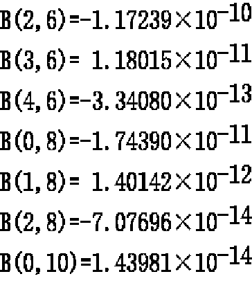
*印が付された面Siは回転対称な非球面であり、その面形状は面頂点を原点とするローカルな直交座標系(x,y,z)を用いた以下の式(AS)で定義される。また、$印が付された面Siは自由曲面(回転非対称な拡張非球面)であり、その面形状は面頂点を原点とするローカルな直交座標系(x,y,z)を用いた以下の式(FS)で定義される。回転対称非球面データ及び自由曲面データを他のデータとあわせて示す(ただし数値がゼロの場合は適宜省略する。)。
【0039】
x=(C0・h2)/{1+√(1−ε・C02・h2)}+Σ{A(i)・hi} …(AS)
x=(C0・h2)/{1+√(1−ε・C02・h2)}+Σ{B(j,k)・yj・zk} …(FS)
ただし、式中、
x:高さhの位置でのx軸方向の基準面からの変位量(面頂点基準)、
h:x軸に対して垂直な方向の高さ(h2=y2+z2)、
C0:面頂点での曲率(正負はx軸に対するものであり、正の場合その曲率中心がベクトルvx上の正方向に存在する。)、
ε:2次曲面パラメータ、
A(i):i次の非球面係数、
B(j,k):yのj次、zのk次の自由曲面係数、
である。
【0040】
表1〜表3に、各実施例の条件式対応値及び関連データを示す。表2は、自由曲面レンズ(Lf)の有効光路径をベクトルvy方向に沿って等分割して成る、断面CSs上の20点CSs1〜CSs20での絶対距離(レンズ厚みに相当)と、そのなかの最大厚みCSsmax及び最小厚みCSsminから得られた差Δdsと、条件式対応値Δds/DLと、を示している。また表3は、自由曲面レンズ(Lf)の有効光路径をベクトルvz方向に沿って等分割して成る、断面CSp上の10点CSp1〜CSp10での絶対距離(レンズ厚みに相当)と、そのなかの最大厚みCSpmax及び最小厚みCSpminから得られた差Δdpと、条件式対応値Δdp/DLと、を示している。断面CSpはxy平面に関して面対称なので、その測定点数を断面CSsでの測定点数の半分である10点としている。なお、測定点CSs1はyの値が最小のとき、測定点CSs20はyの値が最大のとき、測定点CSp1は点Pfと同じ点、測定点CSp10はzの値が最大のときである。
【0041】
![]()
【表1】
【表2】
【表3】
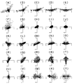
図10〜図12に、各実施例の光学性能をスポットダイアグラムで示す。各スポットダイアグラムは、2次像面(SI)での結像特性(mm,±1スケール)を3波長(450nm,546nm,605nm),25個の評価ポイント(A)〜(Y)について示している。以下に、各評価ポイント(A)〜(Y)のスポット重心の投影位置を2次像面(SI)のローカル座標(x,y;mm)で示す。また、図13に、各スポットの理想的投影位置に対応する1次像面(SO)上の座標(y,z;mm)を示す。2次像面(SI)上での理想的投影位置の値は、図13中の数値に投影倍率βy,βzをかけた値となり、その理想値からのズレは、光学で一般的に言われる歪曲に相当する。なお、第1ミラー(M1)で光路展開すれば{つまり第1ミラー(M1)の反射光学面のベクトルvxをX方向に一致させれば}、いずれの実施例もXY平面に関して対称になっているので、XY平面を中心とした画面片側についてのみスポットの評価ポイントを挙げている。
【0060】
【発明の効果】
以上説明したように本発明によれば、回転対称レンズと自由曲面レンズの各々少なくとも1枚が独立して回転可能な構成になっているため、高精度の偏芯調整が可能である。したがって、良好な光学性能を保持しつつ量産性やコスト面で有利であり、しかも薄型で光学部品もコンパクトな高画角の斜め投影光学系を実現することができる。さらに、自由曲面レンズを絞りから所定値よりも離して配置すれば、像面性を更に良好にすることができる。また、2次像面側レンズ面が2次像面側に凸の自由曲面レンズを屈折レンズ群の最も2次像面側に配置すれば、光路の干渉等なしに結像性能をより一層向上させることができる。自由曲面レンズの有効光路径内の厚みの変化量を適正に制限すれば、良好な光学性能を保持しつつ低コスト化を達成することができ、また、自由曲面レンズの片方の面を光軸に対して回転対称にすれば、偏芯調整を更に容易にすることができる。
【図面の簡単な説明】
【図1】第1の実施の形態(実施例1)の光学構成を示す平面図。
【図2】第1の実施の形態(実施例1)の光学構成を示す側面図。
【図3】図1の要部拡大図。
【図4】第2の実施の形態(実施例2)の光学構成を示す平面図。
【図5】第2の実施の形態(実施例2)の光学構成を示す側面図。
【図6】図4の要部拡大図。
【図7】第3の実施の形態(実施例3)の光学構成を示す平面図。
【図8】第3の実施の形態(実施例3)の光学構成を示す側面図。
【図9】図7の要部拡大図。
【図10】実施例1のスポットダイアグラム。
【図11】実施例2のスポットダイアグラム。
【図12】実施例3のスポットダイアグラム。
【図13】各スポットの理想的投影位置に対応する1次像面上の座標を示す図。
【符号の説明】
SO …1次像面
GL …屈折レンズ群
Lf …自由曲面レンズ
ST …絞り
M1 …第1ミラー(ミラー群の一部)
M2 …第2ミラー(ミラー群の一部)
M3 …第3ミラー(ミラー群の一部)
SI …2次像面
AX …光軸[0001]
TECHNICAL FIELD OF THE INVENTION
BACKGROUND OF THE
[0002]
[Prior art]
2. Description of the Related Art In an image projection apparatus for enlarging and projecting an image displayed on a liquid crystal display (LCD) or the like onto a screen, the image is obliquely projected to reduce the size of the screen and increase the size of the entire projection apparatus. Various devices for enlarging and projecting on a screen have been proposed. Specific examples thereof include a device in which all optical elements of the projection optical system are configured by reflection mirrors (Patent Document 1), a device in which all optical elements of the projection optical system are configured by refractive lenses (Patent Document 2), An apparatus having a projection optical system in which a reflection mirror and a refraction lens are combined (Patent Document 3) is given. In general, utilizing a free-form surface in an optical system having a high angle of view is very effective in improving image quality. In the oblique projection optical system described in
[0003]
[Patent Document 1]
JP-A-10-111474
[Patent Document 2]
JP-A-10-282451
[Patent Document 3]
JP-A-9-179064
[Patent Document 4]
JP-A-2002-122785
[0004]
[Problems to be solved by the invention]
As proposed in
[0005]
As proposed in
[0006]
In the oblique projection optical system proposed in
[0007]
The present invention has been made in view of such circumstances, and has as its object the advantage of mass productivity and cost while maintaining good optical performance, and the high angle of view that is thin and optical components are compact. To provide an oblique projection optical system.
[0008]
[Means for Solving the Problems]
In order to achieve the above object, an oblique projection optical system according to a first aspect of the present invention is an oblique projection optical system that performs diagonally enlarged projection from a primary image plane on a reduction side to a secondary image plane on an enlargement side. A refracting lens group having a plurality of refracting optical surfaces and a mirror group having a negative-power reflecting optical surface in order from the primary image surface side, wherein the refracting lens group has a rotationally symmetric lens surface. A lens, and a free-form surface lens having a lens surface composed of a rotationally asymmetric free-form surface having at most one plane-symmetric symmetry surface, wherein the rotationally symmetric lens forms a coaxial system, At least one of the rotationally symmetric lens and the free-form surface lens is independently rotatable about the optical axis.
[0009]
The oblique projection optical system according to a second aspect of the present invention is the configuration according to the first aspect, wherein a ray passing through the center of the screen of the primary image plane, the center of the stop, and the center of the screen of the secondary image plane is used as a central principal ray. The following conditional expression (1) is satisfied.
L1 / L2 <2 (1)
However,
L1: the absolute distance from the screen center of the primary image plane to the center of the aperture,
L2: the absolute distance from the point closer to the stop to the center of the stop, of the point where the central principal ray intersects the lens surface of the free-form surface lens,
It is.
[0010]
The oblique projection optical system according to a third aspect of the present invention is the oblique projection optical system according to the first or second aspect, wherein the free-form surface lens is located closest to the secondary image surface in the refractive lens group, and one of the free-form surface lenses is provided. The coaxial system is located near the secondary image surface side, and the secondary image surface side lens surface of the free-form surface lens has a convex surface shape on the secondary image surface side.
[0011]
An oblique projection optical system according to a fourth aspect is characterized in that, in the configuration of the first, second, or third aspect, the following conditional expressions (2) and (3) are further satisfied.
Δds / DL ≦ 0.1 (2)
Δdp / DL ≦ 0.1 (3)
However,
DL: screen longest dimension of primary image plane (diagonal dimension if screen shape of primary image plane is rectangular),
Δds: difference between the maximum thickness CSsmax and the minimum thickness CSsmin within the effective optical path diameter of the free-form surface lens,
Δdp: difference between the maximum thickness CSpmax and the minimum thickness CSpmin within the effective optical path diameter of the free-form surface lens,
CSsmax: In the cross section CSs orthogonal to the cross section CSp, the infinite number of points on the line formed by the lens surface where the point Pf exists is closest to the line formed by the lens surface where the point Pf of the free-form surface lens does not exist. The maximum absolute distance to the point,
CSsmin: In the cross section CSs orthogonal to the cross section CSp, the infinite number of points on the line formed by the lens surface where the point Pf exists is closest to the line formed by the lens surface where the point Pf of the free-form lens does not exist. The minimum absolute distance to the point,
CSpmax: In the cross section CSp orthogonal to the cross section CSs, the infinite number of points on the line formed by the lens surface where the point Pf exists is closest to the line formed by the lens surface where the point Pf of the free-form surface lens does not exist. The maximum absolute distance to the point,
CSpmin: In the cross section CSp orthogonal to the cross section CSs, the infinite number of points on the line formed by the lens surface where the point Pf exists is closest to the line formed by the lens surface where the point Pf of the free-form surface lens does not exist. The minimum absolute distance to the point,
Pf: When a ray passing through the center of the screen of the primary image plane, the center of the stop, and the center of the screen of the secondary image plane is set as the central principal ray, the intersection of the central principal ray and one of the lens surfaces of the free-form lens ,
CSs: cross section of the free-form surface lens on a plane passing through the point Pf and having a normal line parallel to the vector V1t;
CSp: cross section of the free-form surface lens on a plane passing through the point Pf and having a normal line parallel to the vector V1s,
V1t: a vector orthogonal to the vector V1n and the vector V1s,
V1n: normal vector of the primary image plane,
V1s: vector from point P1c to point P1s,
P1c: screen center point of primary image plane,
P1s: the point closest to the point P1c on the screen contour line of the primary image plane;
It is.
[0012]
According to a fifth aspect of the present invention, in the oblique projection optical system according to the first, second, third or fourth aspect of the present invention, one of the free-form surface lenses has a center on the optical axis of the coaxial system. It has a rotationally symmetric surface shape.
[0013]
BEST MODE FOR CARRYING OUT THE INVENTION
Hereinafter, an oblique projection optical system embodying the present invention will be described with reference to the drawings. 1 to 9 show first to third embodiments of the oblique projection optical system, respectively. FIGS. 1, 4 and 7 show the optical configuration (optical arrangement, projection optical path, etc.) of the entire projection optical path from the primary image plane (SO) to the secondary image plane (SI) in the first to third embodiments. ) Is shown in a plan view, and FIGS. 2, 5 and 8 show the entire projection optical path from the primary image plane (SO) to the secondary image plane (SI) in the first to third embodiments. The optical configuration (optical arrangement, projection optical path, etc.) is shown in a side view. FIGS. 3, 6, and 9 are enlarged views of main parts of FIGS. 1, 4, and 7, respectively. The vertical arrangement of the optical configuration of each embodiment is not limited to that shown in FIGS. 1 to 9 and may be upside down. That is, there is no problem even if the upper side in FIGS. 1 to 9 is set to the lower side in accordance with the actual arrangement of the apparatus and the arrangement of the optical system. In FIGS. 1 to 9, the optical surfaces marked with * are rotationally symmetric aspherical surfaces, and the optical surfaces marked with Δ are rotationally asymmetric free-form surfaces.
[0014]
The first to third embodiments are directed to an oblique projection optical system for an image projection apparatus, which performs oblique enlargement projection from a reduction-side primary image plane (SO) to an enlargement-side secondary image plane (SI). System. Therefore, the primary image surface (SO) corresponds to an image forming surface (for example, an image display surface) of a light valve that forms a two-dimensional image by modulating light intensity, and the secondary image surface (SI) is a projection image surface. (For example, a screen surface). The glass plate (GP) located near the primary image plane (SO) is a cover glass of the light valve (FIGS. 3, 6, and 9). In each embodiment, a digital micromirror device is used as the light valve. (Digital micromirror device). However, the light valve is not limited to this, and another non-light emitting / reflective (or transmissive) display element (for example, a liquid crystal display element) suitable for the oblique projection optical system of each embodiment may be used.
[0015]
When a digital micromirror device is used as a light valve, the light incident thereon is spatially modulated by being reflected by each micromirror in an ON / OFF state (for example, a tilt state of ± 12 °). . At this time, only the light reflected by the micromirror in the ON state enters the oblique projection optical system and is projected on the screen surface. Note that the oblique projection optical system of each embodiment has an optical configuration suitable for a rear projection type image projection apparatus (rear projector), but from the secondary image plane (SI) to the primary image plane (SO). It is also possible to use an image reading apparatus as an oblique projection optical system for performing a reduced projection in an oblique direction. In this case, the primary image surface (SO) corresponds to the light receiving surface of a light receiving element (for example, a CCD: Charge Coupled Device) for image reading, and the secondary image surface (SI) corresponds to the read image surface (that is, the document surface). I do.
[0016]
The oblique projection optical system according to each of the embodiments includes a refractive lens group (GL), a first mirror (M1), a second mirror (M2), and a third lens (GL) in order from the primary image plane (SO) side (that is, the reduction side). It is composed of a mirror (M3). As shown in FIGS. 3, 6, and 9, the refractive lens group (GL) includes a plurality of refractive lenses constituting a plurality of refractive optical surfaces and a stop (ST). The refracting lens group (GL) includes one free-form surface lens (Lf). Refractive lenses other than the free-form surface lens (Lf) are rotationally symmetric lenses having rotationally symmetric lens surfaces. Has formed. The position of the optical axis (AX) of the coaxial system is shifted by a predetermined amount in the Y direction (the direction perpendicular to the optical axis (AX)) from the center of the screen of the primary image plane (SO), and the refractive lens group (GL) ) Constitute a so-called shift optical system. One lens surface of the free-form surface lens (Lf) is formed of a rotationally asymmetric free-form surface having one plane symmetrical surface (corresponding to an xy plane of a local coordinate system described later), and the other lens surface. Has a surface shape that is rotationally symmetric about the optical axis (AX) of the coaxial system. In the free-form surface of the free-form surface lens (Lf), the surface normal at the intersection with the optical axis (AX) is parallel to the optical axis (AX). Further, in the first and second embodiments, All optical surfaces other than the free-form surface of the free-form surface lens (Lf) are rotationally symmetric with respect to the optical axis (AX).
[0017]
In the mirror group consisting of the first to third mirrors (M1 to M3), the reflecting optical surfaces of the first and third mirrors (M1 and M3) are flat, and the reflecting optical surfaces of the second mirror (M2). Consists of a rotationally symmetric aspheric surface with negative power. Among the used optical elements, the free-form surface lens (Lf) and the second mirror (M2) having a negative power are produced by a molding method such as glass molding, press molding, or injection molding. As a material used for the reflective optical element and the refractive optical element, a material having relatively high fluidity such as plastic is preferable when emphasis is placed on moldability. However, considering the temperature change during actual use, a material having a lower refractive index change or expansion coefficient with respect to temperature change, such as glass, is more preferable than plastic because it can reduce performance degradation due to temperature change. .
[0018]
The use of a free-form surface lens (Lf) having a rotationally asymmetric free-form surface as a lens in a thin oblique projection optical system having a high angle of view as in the first to third embodiments is difficult in terms of image surface properties and the like. It is very effective in achieving high performance by improvement. In general, when trying to achieve a high angle of view and miniaturization of an optical system at the same time, the eccentric sensitivity of an optical element (a lens or a mirror) increases. As for the lens, the eccentricity error that occurs when the lens is incorporated into the lens holding frame increases, and in order to ensure high performance as an integrated lens group, the lens alone or several lenses are rotated with respect to other lenses. It is necessary to make adjustments such as improving the image plane properties of the entire lens group. This is also true for the free-form lens (Lf). Since the eccentricity of the free-form lens (Lf) can be adjusted at the same time, the primary image plane (Lf) as in the first to third embodiments can be adjusted. In order from the (SO) side, it corresponds to a refractive lens group (GL) having a plurality of refractive optical surfaces and a reflective optical surface of negative power {a reflective optical surface of the second mirror (M2). In an oblique projection optical system including a mirror group having}, a lens surface composed of a rotationally symmetric lens having a rotationally symmetric lens surface and a rotationally asymmetric free-form surface having at most one plane symmetrical symmetrical surface. And a free-form surface lens (Lf) having a refractive lens group (GL), a rotationally symmetric lens, a coaxial system, and a rotationally symmetric lens and a free-form surface lens around the optical axis (AX). It is desirable that at least one of (Lf) be independently rotatable.
[0019]
The rotatable lens in the coaxial system composed of the rotationally symmetric lens is determined by the relatively large eccentric sensitivity, the holding structure thereof, and the like. Therefore, by making the lens unit rotatable in units of one lens or a lens group consisting of a plurality of lenses, and by performing the rotation adjustment, the rotation of the coaxial system including the rotationally symmetric lens can be adjusted to the orientation having the highest imaging performance. . If the eccentricity adjustment for the coaxial system thus adjusted by rotation is performed by adjusting the rotation of the free-form surface lens (Lf), the eccentricity of the free-form surface lens (Lf) can be reduced. In a coaxial system, there are a plurality of combinations of arrangements that cancel each other's eccentricity. However, in a free-form surface lens (Lf), since the free-form surface has rotational asymmetry, the optimal arrangement is basically one. Therefore, in the eccentricity adjustment of the free-form surface lens (Lf), the necessary rotation adjustment amount is smaller than the rotation adjustment amount of the rotationally symmetric lens. As long as the rotationally symmetric lens and the free-form surface lens (Lf) whose eccentricity is adjusted can be independently rotated, there is no problem even if the rotation adjustment amounts are different between the two. Therefore, in a state where the holding frame of the coaxial system and the holding frame of the free-form surface lens are fitted, it is possible to arrange the rotatable rotationally symmetric lens and the free-form surface lens at arbitrary rotation positions, thereby. The eccentricity of each lens can be eliminated to improve the image surface properties and the like. In addition, making the lens rotatable as described above is advantageous not only in increasing the angle of view and reducing the thickness of the oblique projection optical system, but also in terms of mass productivity and cost, and contributing to downsizing of optical components. Can be.
[0020]
A reflective optical surface having power, such as a negative optical reflective optical surface of the second mirror (M2), has high optical sensitivity. Therefore, the allowable error amount of the surface shape generated when the negative optical reflecting optical surface (M2) is formed by injection molding or press molding is small, and the manufacturing difficulty is high. If the error of the surface shape generated at the time of molding is corrected again to reduce the surface shape error amount by correcting the mold shape used for molding the negative power reflecting optical surface (M2), the mold correction is required. Accuracy also increases. Further, it becomes more difficult if the reflection optical surface (M2) having a negative power has a large diameter. Therefore, if the surface shape error of the formed negative power reflecting optical surface (M2) is measured or predicted, and the free-form surface lens (Lf) is designed so as to cancel out the aberration that may occur, the optical sensitivity is increased. This is preferable because aberration correction can be performed with a relatively low refractive optical surface, and overall optical performance can be easily improved.
[0021]
Further, it is preferable that the reflection optical surface (M2) having the negative power has a rotationally symmetric shape, because the manufacturing difficulty is reduced. In this case, the mold used for molding the negative power reflective optical surface (M2) by injection molding or press molding has a rotationally symmetric surface shape, but occurs during molding of the negative power reflective optical surface (M2). The resulting surface shape error is not necessarily rotationally symmetric, and a rotationally asymmetric surface shape error also occurs. In order to correct a rotationally asymmetric surface shape error, it is necessary to use a mold processing method involving a rotationally asymmetric operation. It must be used and is cumbersome. Further, a processing method involving a rotationally asymmetric operation has a higher degree of control difficulty than a processing method using a rotationally symmetric operation, and it is difficult to increase the accuracy. Therefore, correction of aberrations that may occur due to rotationally asymmetrical surface shape errors that occur when molding a negative-power rotationally symmetric reflective optical surface can be freely performed by canceling the aberrations using the measured or predicted result of the surface shape after molding. If the curved lens (Lf) is designed, aberration correction can be performed on a refractive optical surface having relatively low optical sensitivity, and it becomes easy to improve the overall optical performance. At the same time, the mold processing operation used for molding the negative optical reflecting optical surface (M2) can be narrowed down to a rotationally symmetrical one. In addition, the rotationally symmetric surface shape error can be achieved by correcting the mold used for molding the negative power rotationally symmetric reflective optical surface by a processing method based on rotationally symmetric operation, but in consideration of optical sensitivity. May be corrected by designing the free-form surface lens (Lf).
[0022]
As in the first to third embodiments, it is preferable to dispose a free-form surface lens (Lf) at a position apart from the stop (ST) in the projection optical path in order to improve the image surface property. In particular, when oblique projection is performed with the position of the optical axis (AX) largely deviated from the center of the primary image plane (SO), a free-form surface is arranged at a position away from the stop (ST) in the refraction lens group (GL). Then, the effect of improving the image surface properties is further enhanced. Therefore, it is preferable to arrange the free-form surface at a position closer to the primary image plane (SO) or the secondary image plane (SI) with respect to the stop (ST). When it is arranged on the secondary image plane (SI) side from the stop (ST), it corresponds to the negative optical power reflecting optical surface {the reflective optical surface of the second mirror (M2). The size of the free-form surface lens (Lf) can be reduced by arranging the free-form surface lens (Lf) on the primary image plane (SO) side. Therefore, it is possible to reduce cost and manufacturing difficulty.
[0023]
The preferred position of the free-form surface lens (Lf) will be described in more detail. When a ray passing through the center of the screen of the primary image plane (SO), the center of the stop (ST), and the center of the screen of the secondary image plane (SI) is set as a central principal ray, the following conditional expression (1) is satisfied. Is desirable.
L1 / L2 <2 (1)
However,
L1: the absolute distance from the center of the screen of the primary image plane (SO) to the center of the stop (ST),
L2: absolute distance from a point closer to the stop (ST) to a center of the stop (ST) from a point where the central principal ray intersects the lens surface of the free-form surface lens (Lf),
It is.
[0024]
When oblique projection is performed using a shift optical system in which the position of the optical axis (AX) of the coaxial system is shifted from the center of the primary image plane (SO) as in the first to third embodiments, If the free-form surface is arranged at a position distant from the stop (ST), the image surface property can be effectively improved as described above. On the other hand, if a free-form surface is arranged near the stop (ST), light beams emitted from different places on the primary image surface (SO) overlap, and therefore, different changes can be applied to the respective light beams. And the image plane correction effect is reduced. If the free-form surface is arranged so as to satisfy the conditional expression (1), this problem can be effectively solved.
[0025]
It is desirable to satisfy the following conditional expressions (1a), and it is more desirable to satisfy the conditional expressions (1b). The conditional expressions (1a) and (1b) define a more preferable condition range from the above viewpoints among the condition ranges defined by the conditional expression (1).
L1 / L2 <1 (1a)
L1 / L2 <0.5 (1b)
[0026]
As in the first and third embodiments, the free-form surface lens (Lf) is located closest to the secondary image plane (SI) in the refractive lens group (GL), and one of the free-form surface lenses (Lf) is located. The coaxial system is located near the secondary image plane (SO) side, and the secondary image plane (SI) side lens surface of the free-form surface lens (Lf) has a convex surface shape on the secondary image plane (SI) side. It is preferred to have. Since the free-form surface lens (Lf) has a lens surface composed of a rotationally asymmetric free-form surface, it is important how the amount of eccentricity with respect to other optical elements (lenses, mirrors, etc.) can be reduced when incorporated into the holding frame. However, when assembling the lenses constituting the refractive lens group (GL) into the holding frame, some eccentric errors occur between each lens axis and the optical axis (AX) as described above. Become. In a shift optical system in which the optical axis (AX) does not coincide with the center of the primary image plane (SO), the built-in lens is rotated together with the holding frame to adjust the rotation to the orientation having the highest imaging performance. Can be. At that time, if the holding frame of the free-form surface lens (Lf) is located near the holding frame of the rotationally symmetric lens, it is possible to reduce the eccentric sensitivity and reduce the amount of eccentricity of each other, It is more effective if the holding frames are brought into contact with each other. On the other hand, if the free-form surface lens (Lf) is disposed closest to the primary image plane (SO) in the refraction lens group (GL), the eccentricity sensitivity becomes too high, and the reflection type light valve is used. Causes optical path interference.
[0027]
Further, when pursuing a reduction in the mutual eccentricity between the holding frames, the position of the holding frame of the free-form surface lens (Lf) with respect to the position of the holding frame of the rotationally symmetric lens forming the coaxial system is adjusted. It is desirable to provide a parallel eccentricity adjusting mechanism and a tilt eccentricity adjusting mechanism on the holding frame of the curved lens (Lf). When the lens surface on the secondary image surface (SI) side of the free-form surface lens (Lf) has a convex surface facing the secondary image surface (SI) side as in the first and third embodiments, The shape outside the effective diameter of the curved lens (Lf) and the shape of the holding frame can be retracted in a direction away from the secondary image plane (SI). Thereby, interference between the holding frame of the free-form surface lens (Lf) and the optical path can be reduced. That is, interference (between the optical path and the holding frame) that occurs when the optical path is turned back can be prevented, and the projection optical system can be made thinner.
[0028]
It is preferable that the free-form surface lens (Lf) satisfies the following conditional expressions (2) and (3). Note that the vectors vx, vy, and vz are coordinate axis vectors of a local rectangular coordinate system (x, y, z) described later that specify each optical surface.
Δds / DL ≦ 0.1 (2)
Δdp / DL ≦ 0.1 (3)
However,
DL: the longest screen size of the primary image plane (SO) {the diagonal dimension if the screen shape of the primary image plane (SO) is rectangular},
Δds: difference between the maximum thickness CSsmax and the minimum thickness CSsmin within the effective optical path diameter of the free-form surface lens (Lf),
Δdp: difference between the maximum thickness CSpmax and the minimum thickness CSpmin within the effective optical path diameter of the free-form surface lens (Lf),
CSsmax: In a cross section CSs orthogonal to the cross section CSp, an infinite number of points on a line formed by a lens surface on which a point Pf exists is on a line formed by a lens surface on which the point Pf of the free-form surface lens (Lf) does not exist. The maximum value of the absolute distance to the nearest point,
CSsmin: In a cross section CSs orthogonal to the cross section CSp, from innumerable points on the line formed by the lens surface where the point Pf exists, on the line formed by the lens surface where the point Pf of the free-form surface lens (Lf) does not exist The minimum of the absolute distance to the nearest point,
CSpmax: on a line formed by a lens surface where the point Pf of the free-form surface lens (Lf) does not exist, from an infinite number of points on a line formed by the lens surface where the point Pf exists on the cross section CSp orthogonal to the cross section CSs. The maximum value of the absolute distance to the nearest point,
CSpmin: on a line formed by a lens surface where the point Pf of the free-form surface lens (Lf) does not exist, from innumerable points on a line formed by the lens surface where the point Pf exists on a cross section CSp orthogonal to the cross section CSs. The minimum of the absolute distance to the nearest point,
Pf: When a ray passing through the center of the screen of the primary image plane (SO), the center of the stop (ST), and the center of the screen of the secondary image plane (SI) is set as a central principal ray, the central principal ray and a free-form surface lens (Lf) the intersection with any of the lens surfaces,
CSs: cross section of the free-form surface lens (Lf) on a plane passing through the point Pf and having a normal line parallel to the vector V1t;
CSp: a cross section of the free-form surface lens (Lf) on a plane passing through the point Pf and having a normal line parallel to the vector V1s,
V1t: vector {vector vz on primary image plane (SO)} orthogonal to vector V1n and vector V1s,
V1n: normal vector of primary image plane (SO) {vector vx on primary image plane (SO)},
V1s: vector {vector vy on primary image plane (SO)} from point P1c to point P1s,
P1c: screen center point of primary image plane (SO),
P1s: a point closest to the point P1c on the screen contour line of the primary image plane (SO);
It is.
[0029]
The conditional expressions (2) and (3) define a preferable range for the amount of change in the thickness of the free-form surface lens (Lf) within the effective optical path diameter. When a stress caused by expansion / contraction of the lens due to a temperature change, gravity, an adhesive, fixing, or the like occurs in the free-form surface lens (Lf), it causes deterioration of optical performance. If the conditional expressions (2) and (3) are satisfied, the optical power of the free-form surface lens (Lf) is reduced, so that the deterioration of the optical performance due to the stress is reduced. In addition, when injection molding, press molding, or the like is used as a method for molding the free-form surface lens (Lf), molding errors due to gravity during the molding process, stress when the mold is separated, temperature changes, and the like are less likely to occur. Therefore, it is possible to reduce the eccentric sensitivity of the free-form surface and to reduce the cost.
[0030]
It is desirable to satisfy the following conditional expressions (2a) and (3a), and it is more desirable to satisfy the conditional expressions (2b) and (3b). The conditional expressions (2a) and (3a) and the conditional expressions (2b) and (3b) are more preferable conditions from the above viewpoints, etc., even within the conditional ranges defined by the conditional expressions (2) and (3). The range is specified.
Δds / DL ≦ 0.02 (2a)
Δdp / DL ≦ 0.02 (3a)
Δds / DL ≦ 0.01 (2b)
Δdp / DL ≦ 0.01 (3b)
[0031]
Further, as in the first to third embodiments, it is preferable that one lens surface of the free-form surface lens (Lf) has a surface shape that is rotationally symmetric about the optical axis (AX) of the coaxial system. . If one surface of the free-form surface lens (Lf) is rotationally symmetric with respect to the optical axis (AX), the eccentricity of aligning the lens axis of the free-form surface lens (Lf) with the optical axis (AX) of the coaxial system. Adjustment becomes easy. This allows the free-form surface lens (Lf) to be adjusted for eccentricity in the same manner as the rotationally symmetric lens, thereby facilitating high performance and low cost. If a spherical surface is adopted as the rotationally symmetric surface shape, the eccentricity of the free curved surface can be adjusted at the center of curvature of the spherical surface by using the spherical surface as a holding reference surface of the free curved lens (Lf). . In addition, if a plane is adopted as the rotationally symmetric surface shape, the free-form lens (Lf) can be held in the free-form lens (Lf) within the holding frame without decentering the holding frame itself parallel to other optical surfaces. ) Can be adjusted.
[0032]
As in the first to third embodiments, at the intersection of the optical axis (AX) of the coaxial system and the free-form surface of the free-form surface lens (Lf), the surface normal of the free-form surface coincides with the optical axis (AX). Preferably they are parallel. If the surface normal on the optical axis (AX) of the free-form surface coincides with the optical axis (AX) of the coaxial system, eccentricity adjustment can be performed for one optical axis (AX). Therefore, the eccentricity adjustment can be simplified. Regarding the simplification of the eccentricity adjustment, as in the first and second embodiments, all the optical surfaces other than the free-form surface of the free-form surface lens (Lf) are aligned with the optical axis (AX) of the coaxial system. On the other hand, it is desirable to have rotational symmetry. However, when the optical path is turned back by a plane reflecting optical surface such as a plane mirror, the optical axis (AX) is bent according to the law of reflection.
[0033]
The above embodiments include inventions (A1) to (A7) and (B1) to (B7) having the following configurations. According to these configurations, an oblique projection optical system that is advantageous in terms of mass productivity and cost while maintaining good optical performance, and that is thin and has compact optical components with a high angle of view can be realized. By applying it to a rear projection type image projection device, it is possible to contribute to a reduction in thickness, size, performance, and cost of the device.
[0034]
(A1) An oblique projection optical system that performs diagonal enlargement projection from a primary image plane on a reduction side to a secondary image plane on an enlargement side, and has a plurality of refractive optical surfaces in order from the primary image plane side. A refracting lens group, and a mirror group having a negative optical reflecting optical surface, wherein the refracting lens group has at most one rotationally symmetric lens having a rotationally symmetric lens surface and at most one plane symmetrical symmetric surface. A free-form surface lens having a lens surface composed of a rotationally asymmetric free-form surface, wherein the rotationally symmetric lens forms a coaxial system, and the rotationally symmetric lens and the free-form surface lens around its optical axis. Wherein the eccentricity is adjusted by independently rotating at least one of the optical systems.
(A2) When a light ray passing through the center of the screen of the primary image plane, the center of the aperture, and the center of the screen of the secondary image plane is set as a central principal ray, among the conditional expressions (1), (1a), and (1b), The oblique projection optical system according to the above (A1), wherein at least one of the following is satisfied.
(A3) The free-form surface lens is located closest to the secondary image surface in the refractive lens group, and the coaxial system is located near the primary image surface side of the free-form surface lens. The oblique projection optical system according to the above (A1) or (A2), wherein the secondary image plane side lens surface has a convex surface shape on the secondary image plane side.
(A4) Further, at least one of the conditional expressions (2), (2a) and (2b) and at least one of the conditional expressions (3), (3a) and (3b) are satisfied. The oblique projection optical system according to the above (A1), (A2) or (A3).
(A5) The one of (A1), (A2), (A3) or (A3), wherein one lens surface of the free-form surface lens has a rotationally symmetric surface shape about the optical axis of the coaxial system. A4) The oblique projection optical system according to the above.
(A6) At the intersection of the optical axis of the coaxial system and the free-form surface of the free-form surface lens, the surface normal of the free-form surface is parallel to the optical axis, (A1), (A2). ), (A3), (A4) or (A5).
(A7) All of the optical surfaces other than the free-form surface of the free-form surface lens are rotationally symmetric with respect to the optical axis of the coaxial system, wherein (A1), (A2), (A3), The oblique projection optical system according to (A4), (A5) or (A6).
[0035]
(B1) A method for manufacturing an oblique projection optical system that performs oblique enlargement projection from a primary image plane on a reduction side to a secondary image plane on an enlargement side, comprising a plurality of refractive optics in order from the primary image plane side. A refracting lens group having a surface and a mirror group having a negative optical reflecting optical surface are arranged, and a rotationally symmetric lens having a rotationally symmetric lens surface and a rotationally asymmetric having at most one plane symmetrical symmetrical surface. And a free-form surface lens having a lens surface composed of a free-form surface, the refraction lens group being constituted, a coaxial system being constituted by the rotationally symmetric lens, and the rotationally symmetric lens and the free-form surface being centered on the optical axis. A method for manufacturing an oblique projection optical system, wherein eccentricity adjustment is performed by independently rotating at least one of the lenses.
(B2) When a light ray passing through the center of the screen of the primary image plane, the center of the aperture, and the center of the screen of the secondary image plane is set as a central principal ray, among the conditional expressions (1), (1a), and (1b), The manufacturing method of the oblique projection optical system according to the above (B1), wherein at least one of the following is satisfied.
(B3) The free-form surface lens is located closest to the secondary image surface in the refractive lens group, and the coaxial system is located near the primary image surface side of the free-form surface lens. The method for manufacturing an oblique projection optical system according to the above (B1) or (B2), wherein the secondary image plane side lens surface has a surface shape convex toward the secondary image plane side.
(B4) Further, at least one of the conditional expressions (2), (2a) and (2b) and at least one of the conditional expressions (3), (3a) and (3b) are satisfied. The method for producing an oblique projection optical system according to the above (B1), (B2) or (B3).
(B5) The one of (B1), (B2), (B3) or (B3), wherein one lens surface of the free-form surface lens has a rotationally symmetric surface shape about the optical axis of the coaxial system. B4) The method for manufacturing the oblique projection optical system according to the above.
(B6) At the intersection of the optical axis of the coaxial system and the free-form surface of the free-form surface lens, the surface normal of the free-form surface is parallel to the optical axis, (B1), (B2). ), (B3), (B4) or (B5).
(B7) All of the optical surfaces other than the free-form surface of the free-form surface lens are rotationally symmetric with respect to the optical axis of the coaxial system, wherein (B1), (B2), (B3), The manufacturing method of the oblique projection optical system according to (B4), (B5) or (B6).
[0036]
【Example】
Hereinafter, the oblique projection optical system embodying the present invention will be described more specifically with reference to construction data and the like. Examples 1 to 3 given here are numerical examples corresponding to the above-described first to third embodiments, respectively, and the optical configuration diagrams (FIGS. 1 to 9) showing the respective embodiments correspond to the corresponding numerical examples. 1 shows an optical arrangement, a projection optical path, and the like of the embodiment.
[0037]
In the construction data of each embodiment, from the primary image plane on the reduction side (SO; corresponding to an object plane in enlarged projection) to the secondary image plane on the enlargement side (SI; corresponding to an image plane in enlarged projection). , The i-th surface counted from the reduction side is Si (i = 1, 2, 3,...), And ri (i = 1, 2, 3,. (RO: radius of curvature of surface SO, rI: radius of curvature of surface SI). Di (i = 1, 2, 3,...) Indicates the i-th axial distance (mm) from the reduction side (that is, between the surface Si and the surface Si + 1) (dO: surface The axial top surface distance from SO to the surface S1), Ni (i = 1, 2, 3,...), And νi (i = 1, 2, 3,...) Are the i-th optical elements counted from the reduction side. The refractive index (Nd) and Abbe number (νd) of the element with respect to d-line are shown. The arrangement of the mirror group (M1 to M3) and the secondary image plane (SI) is based on the global orthogonal coordinate system using the surface vertex of the optical surface as the origin (o) of the local orthogonal coordinate system (x, y, z). The origin (o) of the local rectangular coordinate system (x, y, z) in (X, Y, Z) and the coordinate data (X, vy, vz) of the coordinate axis vector (vx, vy, vz) of the x, y, and z axes Y, Z) (unit: mm). The global rectangular coordinate system (X, Y, Z) is an absolute coordinate system that matches the local rectangular coordinate system (x, y, z) of the primary image plane (SO). di represents a numerical value in the X direction. Note that the projection magnifications βy and βz for distortion calculation described later are also shown for the y direction and the z direction.
[0038]
The surface Si marked with * is a rotationally symmetric aspherical surface, and its surface shape is defined by the following equation (AS) using a local rectangular coordinate system (x, y, z) whose origin is the vertex of the surface. Is done. The surface Si marked with a symbol $ is a free-form surface (a rotationally asymmetric extended aspheric surface), and its surface shape is as follows using a local orthogonal coordinate system (x, y, z) with the origin at the surface vertex. (FS). The rotationally symmetric aspherical data and the free-form surface data are shown together with other data (however, when the numerical value is zero, it is omitted as appropriate).
[0039]
x = (C0 · h 2 ) / {1 +} (1-ε · C0 2 ・ H 2 )} + Σ {A (i) · h i …… (AS)
x = (C0 · h 2 ) / {1 +} (1-ε · C0 2 ・ H 2 )} + Σ {B (j, k) · y j ・ Z k }… (FS)
Where,
x: displacement amount from the reference plane in the x-axis direction at the position of height h (based on the surface vertex);
h: height in the direction perpendicular to the x-axis (h 2 = Y 2 + Z 2 ),
C0: curvature at the surface vertex (positive / negative is with respect to the x-axis, and if positive, the center of curvature exists in the positive direction on the vector vx);
ε: quadratic surface parameter,
A (i): i-th order aspherical coefficient,
B (j, k): j-th free surface coefficient of y, k-th free surface coefficient of z,
It is.
[0040]
Tables 1 to 3 show values corresponding to conditional expressions and related data of each example. Table 2 shows absolute distances (corresponding to lens thickness) at 20 points CSs1 to CSs20 on the cross section CSs, which are obtained by equally dividing the effective optical path diameter of the free-form surface lens (Lf) along the vector vy direction. 2 shows a difference Δds obtained from the maximum thickness CSsmax and the minimum thickness CSsmin, and a conditional expression corresponding value Δds / DL. Table 3 shows absolute distances (corresponding to lens thickness) at ten points CSp1 to CSp10 on the cross section CSp, which are obtained by equally dividing the effective optical path diameter of the free-form surface lens (Lf) along the vector vz direction. The difference Δdp obtained from the maximum thickness CSpmax and the minimum thickness CSpmin therein and the conditional expression corresponding value Δdp / DL are shown. Since the cross section CSp is plane-symmetric with respect to the xy plane, the number of measurement points is set to 10 which is half the number of measurement points in the cross section CSs. The measurement point CSs1 is when the value of y is minimum, the measurement point CSs20 is when the value of y is maximum, the measurement point CSp1 is the same point as the point Pf, and the measurement point CSp10 is when the value of z is maximum.
[0041]
![]()
[Table 1]
[Table 2]
[Table 3]
10 to 12 show the optical performances of the respective examples by spot diagrams. Each spot diagram shows the imaging characteristics (mm, ± 1 scale) on the secondary image plane (SI) for three wavelengths (450 nm, 546 nm, 605 nm) and 25 evaluation points (A) to (Y). I have. In the following, the projection position of the spot centroid at each of the evaluation points (A) to (Y) is shown by local coordinates (x, y; mm) on the secondary image plane (SI). FIG. 13 shows coordinates (y, z; mm) on the primary image plane (SO) corresponding to the ideal projection position of each spot. The value of the ideal projection position on the secondary image plane (SI) is a value obtained by multiplying the numerical values in FIG. 13 by the projection magnifications βy and βz, and the deviation from the ideal value is generally referred to in optics. Corresponds to distortion. If the optical path is developed by the first mirror (M1) {that is, if the vector vx of the reflection optical surface of the first mirror (M1) is made to coincide with the X direction}, both embodiments are symmetric with respect to the XY plane. Therefore, the evaluation points of the spots are given only on one side of the screen centering on the XY plane.
[0060]
【The invention's effect】
As described above, according to the present invention, since at least one of each of the rotationally symmetric lens and the free-form surface lens is configured to be independently rotatable, highly accurate eccentricity adjustment is possible. Therefore, an oblique projection optical system that is advantageous in terms of mass productivity and cost while maintaining good optical performance, and that is thin and has compact optical components and a high angle of view can be realized. Further, if the free-form surface lens is arranged at a distance from the stop that is larger than a predetermined value, the image quality can be further improved. Further, if a free-form surface lens whose secondary image surface side lens surface is convex on the secondary image surface side is disposed closest to the secondary image surface side of the refraction lens group, the imaging performance is further improved without interference of the optical path and the like. Can be done. By appropriately limiting the amount of change in the thickness of the free-form lens within the effective optical path diameter, cost reduction can be achieved while maintaining good optical performance. By making the rotation symmetrical with respect to, the eccentricity adjustment can be further facilitated.
[Brief description of the drawings]
FIG. 1 is a plan view showing an optical configuration of a first embodiment (Example 1).
FIG. 2 is a side view showing the optical configuration of the first embodiment (Example 1).
FIG. 3 is an enlarged view of a main part of FIG. 1;
FIG. 4 is a plan view showing an optical configuration of a second embodiment (Example 2).
FIG. 5 is a side view showing the optical configuration of the second embodiment (Example 2).
FIG. 6 is an enlarged view of a main part of FIG. 4;
FIG. 7 is a plan view showing an optical configuration of a third embodiment (Example 3).
FIG. 8 is a side view showing the optical configuration of the third embodiment (Example 3).
FIG. 9 is an enlarged view of a main part of FIG. 7;
FIG. 10 is a spot diagram of Example 1.
FIG. 11 is a spot diagram of Example 2.
FIG. 12 is a spot diagram of Example 3.
FIG. 13 is a diagram showing coordinates on a primary image plane corresponding to an ideal projection position of each spot.
[Explanation of symbols]
SO: Primary image plane
GL: Refractive lens group
Lf: Free-form surface lens
ST… aperture
M1... First mirror (part of the mirror group)
M2: Second mirror (part of the mirror group)
M3: Third mirror (part of the mirror group)
SI: Secondary image plane
AX: Optical axis
Claims (5)
前記屈折レンズ群が、回転対称なレンズ面を有する回転対称レンズと、面対称の対称面を多くとも1面しか持たない回転非対称な自由曲面から成るレンズ面を有する自由曲面レンズと、で構成されており、前記回転対称レンズが共軸系を成し、その光軸を中心に、前記回転対称レンズと前記自由曲面レンズの各々少なくとも1枚が独立して回転可能であることを特徴とする斜め投影光学系。A diagonal projection optical system for performing diagonal enlargement projection from a reduction-side primary image plane to an enlargement-side secondary image plane, and a refractive lens group having a plurality of refractive optical surfaces in order from the primary image plane And a mirror group having a reflective optical surface of negative power,
The refracting lens group includes a rotationally symmetric lens having a rotationally symmetric lens surface, and a free-form surface lens having a lens surface composed of a rotationally asymmetric free-form surface having at most one plane-symmetric symmetry surface. Wherein the rotationally symmetric lens forms a coaxial system, and at least one of the rotationally symmetric lens and the free-form surface lens is independently rotatable about its optical axis. Projection optics.
L1/L2<2 …(1)
ただし、
L1:1次像面の画面中心から絞りの中心までの絶対距離、
L2:中心主光線が自由曲面レンズのレンズ面と交わる点のうち絞りに近い方の点から絞りの中心までの絶対距離、
である。2. The optical system according to claim 1, wherein the following conditional expression (1) is satisfied when a ray passing through the center of the screen of the primary image plane, the center of the stop, and the center of the screen of the secondary image plane is set as a central principal ray. Oblique projection optical system;
L1 / L2 <2 (1)
However,
L1: the absolute distance from the screen center of the primary image plane to the center of the aperture,
L2: the absolute distance from the point closer to the stop to the center of the stop, of the point where the central principal ray intersects the lens surface of the free-form surface lens,
It is.
Δds/DL≦0.1 …(2)
Δdp/DL≦0.1 …(3)
ただし、
DL:1次像面の画面最長寸法(1次像面の画面形状が四角形であれば対角線の寸法)、
Δds:自由曲面レンズの有効光路径内の最大厚みCSsmaxと最小厚みCSsminとの差、
Δdp:自由曲面レンズの有効光路径内の最大厚みCSpmaxと最小厚みCSpminとの差、
CSsmax:断面CSpと直交する断面CSsにおいて、点Pfが存在するレンズ面が成す線上の無数に存在する各点から、自由曲面レンズの点Pfが存在しない方のレンズ面が成す線上でそれぞれ最も近い点までの絶対距離の最大値、
CSsmin:断面CSpと直交する断面CSsにおいて、点Pfが存在するレンズ面が成す線上の無数に存在する各点から、自由曲面レンズの点Pfが存在しない方のレンズ面が成す線上でそれぞれ最も近い点までの絶対距離の最小値、
CSpmax:断面CSsと直交する断面CSpにおいて、点Pfが存在するレンズ面が成す線上の無数に存在する各点から、自由曲面レンズの点Pfが存在しない方のレンズ面が成す線上でそれぞれ最も近い点までの絶対距離の最大値、
CSpmin:断面CSsと直交する断面CSpにおいて、点Pfが存在するレンズ面が成す線上の無数に存在する各点から、自由曲面レンズの点Pfが存在しない方のレンズ面が成す線上でそれぞれ最も近い点までの絶対距離の最小値、
Pf:1次像面の画面中心,絞りの中心及び2次像面の画面中心を通過する光線を中心主光線とするとき、その中心主光線と自由曲面レンズのいずれかのレンズ面との交点、
CSs:点Pfを通り、かつ、法線がベクトルV1tと平行な平面での自由曲面レンズの断面、
CSp:点Pfを通り、かつ、法線がベクトルV1sと平行な平面での自由曲面レンズの断面、
V1t:ベクトルV1nとベクトルV1sに直交するベクトル、
V1n:1次像面の法線ベクトル、
V1s:点P1cから点P1sへのベクトル、
P1c:1次像面の画面中心点、
P1s:1次像面の画面輪郭線において点P1cから最も近い点、
である。4. The oblique projection optical system according to claim 1, wherein the following conditional expressions (2) and (3) are further satisfied:
Δds / DL ≦ 0.1 (2)
Δdp / DL ≦ 0.1 (3)
However,
DL: screen longest dimension of primary image plane (diagonal dimension if screen shape of primary image plane is rectangular),
Δds: difference between the maximum thickness CSsmax and the minimum thickness CSsmin within the effective optical path diameter of the free-form surface lens,
Δdp: difference between the maximum thickness CSpmax and the minimum thickness CSpmin within the effective optical path diameter of the free-form surface lens,
CSsmax: In the cross section CSs orthogonal to the cross section CSp, the infinite number of points on the line formed by the lens surface where the point Pf exists is closest to the line formed by the lens surface where the point Pf of the free-form surface lens does not exist. The maximum absolute distance to the point,
CSsmin: In the cross section CSs orthogonal to the cross section CSp, the infinite number of points on the line formed by the lens surface where the point Pf exists is closest to the line formed by the lens surface where the point Pf of the free-form lens does not exist. The minimum absolute distance to the point,
CSpmax: In the cross section CSp orthogonal to the cross section CSs, the infinite number of points on the line formed by the lens surface where the point Pf exists is closest to the line formed by the lens surface where the point Pf of the free-form surface lens does not exist. The maximum absolute distance to the point,
CSpmin: In the cross section CSp orthogonal to the cross section CSs, the infinite number of points on the line formed by the lens surface where the point Pf exists is closest to the line formed by the lens surface where the point Pf of the free-form surface lens does not exist. The minimum absolute distance to the point,
Pf: When a ray passing through the center of the screen of the primary image plane, the center of the stop, and the center of the screen of the secondary image plane is set as the central principal ray, the intersection of the central principal ray and one of the lens surfaces of the free-form lens ,
CSs: cross section of the free-form surface lens on a plane passing through the point Pf and having a normal line parallel to the vector V1t;
CSp: cross section of the free-form surface lens on a plane passing through the point Pf and having a normal line parallel to the vector V1s,
V1t: a vector orthogonal to the vector V1n and the vector V1s,
V1n: normal vector of the primary image plane,
V1s: vector from point P1c to point P1s,
P1c: screen center point of primary image plane,
P1s: the point closest to the point P1c on the screen contour line of the primary image plane;
It is.
Priority Applications (1)
| Application Number | Priority Date | Filing Date | Title |
|---|---|---|---|
| JP2003047846A JP4374868B2 (en) | 2003-02-25 | 2003-02-25 | Oblique projection optical system |
Applications Claiming Priority (1)
| Application Number | Priority Date | Filing Date | Title |
|---|---|---|---|
| JP2003047846A JP4374868B2 (en) | 2003-02-25 | 2003-02-25 | Oblique projection optical system |
Publications (2)
| Publication Number | Publication Date |
|---|---|
| JP2004258218A true JP2004258218A (en) | 2004-09-16 |
| JP4374868B2 JP4374868B2 (en) | 2009-12-02 |
Family
ID=33113977
Family Applications (1)
| Application Number | Title | Priority Date | Filing Date |
|---|---|---|---|
| JP2003047846A Expired - Fee Related JP4374868B2 (en) | 2003-02-25 | 2003-02-25 | Oblique projection optical system |
Country Status (1)
| Country | Link |
|---|---|
| JP (1) | JP4374868B2 (en) |
Cited By (19)
| Publication number | Priority date | Publication date | Assignee | Title |
|---|---|---|---|---|
| JP2006085019A (en) * | 2004-09-17 | 2006-03-30 | Mitsubishi Electric Corp | Image display apparatus |
| JP2006138882A (en) * | 2004-11-10 | 2006-06-01 | Konica Minolta Opto Inc | Oblique projection optical system |
| JP2006154719A (en) * | 2004-11-01 | 2006-06-15 | Hitachi Ltd | Image display apparatus, and, fresnel lens sheet and screen to be used therein |
| JP2006195433A (en) * | 2004-12-13 | 2006-07-27 | Nitto Kogaku Kk | Optical system and rear projector |
| JP2006292901A (en) * | 2005-04-08 | 2006-10-26 | Hitachi Ltd | Projection optical unit and projection type video display device using same |
| JP2006292900A (en) * | 2005-04-08 | 2006-10-26 | Hitachi Ltd | Projection optical unit and projection type image display apparatus using the same |
| JP2007017707A (en) * | 2005-07-07 | 2007-01-25 | Matsushita Electric Ind Co Ltd | Projection optical system and video-enlarging and projecting system using projection optical system, and video projector, and projection television |
| JP2007094405A (en) * | 2005-09-26 | 2007-04-12 | Samsung Electronics Co Ltd | Projection type image display device |
| EP1783527A1 (en) * | 2005-11-04 | 2007-05-09 | Hitachi, Ltd. | Projection type image display |
| JP2007164007A (en) * | 2005-12-16 | 2007-06-28 | Hitachi Ltd | Optical element having free curved surface, and projective optical unit including the optical element or projection type image display apparatus |
| JP2007192856A (en) * | 2006-01-17 | 2007-08-02 | Mitsubishi Electric Corp | Projection type image display device |
| EP1868032A2 (en) * | 2006-06-01 | 2007-12-19 | Hitachi, Ltd. | Projection-type image display apparatus |
| JP2011175277A (en) * | 2011-04-11 | 2011-09-08 | Hitachi Ltd | Projection optical unit and projection image display device using the same |
| JP2011175293A (en) * | 2004-11-01 | 2011-09-08 | Hitachi Ltd | Image display apparatus, and fresnel lens sheet and screen used for the image display apparatus |
| JP2011180609A (en) * | 2011-04-25 | 2011-09-15 | Hitachi Ltd | Projection optical unit and projection type image display apparatus using the same |
| CN101840141B (en) * | 2006-06-08 | 2012-09-05 | 株式会社日立制作所 | Projection type image display device |
| JP2013008044A (en) * | 2012-08-23 | 2013-01-10 | Hitachi Ltd | Projection type display device |
| CN112346209A (en) * | 2019-08-09 | 2021-02-09 | 华为技术有限公司 | Camera module and terminal equipment |
| EP4001987A1 (en) * | 2020-11-18 | 2022-05-25 | Coretronic Corporation | Imaging system and projection device |
-
2003
- 2003-02-25 JP JP2003047846A patent/JP4374868B2/en not_active Expired - Fee Related
Cited By (31)
| Publication number | Priority date | Publication date | Assignee | Title |
|---|---|---|---|---|
| JP2006085019A (en) * | 2004-09-17 | 2006-03-30 | Mitsubishi Electric Corp | Image display apparatus |
| JP2006154719A (en) * | 2004-11-01 | 2006-06-15 | Hitachi Ltd | Image display apparatus, and, fresnel lens sheet and screen to be used therein |
| JP2011175293A (en) * | 2004-11-01 | 2011-09-08 | Hitachi Ltd | Image display apparatus, and fresnel lens sheet and screen used for the image display apparatus |
| US7670008B2 (en) | 2004-11-10 | 2010-03-02 | Konica Minolta Opto, Inc. | Oblique projection optical system |
| JP2006138882A (en) * | 2004-11-10 | 2006-06-01 | Konica Minolta Opto Inc | Oblique projection optical system |
| JP2006195433A (en) * | 2004-12-13 | 2006-07-27 | Nitto Kogaku Kk | Optical system and rear projector |
| JP2006292901A (en) * | 2005-04-08 | 2006-10-26 | Hitachi Ltd | Projection optical unit and projection type video display device using same |
| JP2006292900A (en) * | 2005-04-08 | 2006-10-26 | Hitachi Ltd | Projection optical unit and projection type image display apparatus using the same |
| CN101788748B (en) * | 2005-04-08 | 2013-11-06 | 株式会社日立制作所 | Projection display device |
| CN101788747B (en) * | 2005-04-08 | 2013-06-12 | 株式会社日立制作所 | Projection display device |
| CN101788747A (en) * | 2005-04-08 | 2010-07-28 | 株式会社日立制作所 | Projection display device |
| JP2007017707A (en) * | 2005-07-07 | 2007-01-25 | Matsushita Electric Ind Co Ltd | Projection optical system and video-enlarging and projecting system using projection optical system, and video projector, and projection television |
| JP2007094405A (en) * | 2005-09-26 | 2007-04-12 | Samsung Electronics Co Ltd | Projection type image display device |
| US7789516B2 (en) | 2005-09-26 | 2010-09-07 | Samsung Electronics Co., Ltd. | Projection type image display device |
| CN100456082C (en) * | 2005-09-26 | 2009-01-28 | 三星电子株式会社 | Projection type image display device |
| JP2007127865A (en) * | 2005-11-04 | 2007-05-24 | Hitachi Ltd | Projection type image display apparatus and projection optical unit therefor |
| EP1783527A1 (en) * | 2005-11-04 | 2007-05-09 | Hitachi, Ltd. | Projection type image display |
| US7535648B2 (en) | 2005-11-04 | 2009-05-19 | Hitachi, Ltd. | Projection type image display |
| JP2007164007A (en) * | 2005-12-16 | 2007-06-28 | Hitachi Ltd | Optical element having free curved surface, and projective optical unit including the optical element or projection type image display apparatus |
| JP2007192856A (en) * | 2006-01-17 | 2007-08-02 | Mitsubishi Electric Corp | Projection type image display device |
| US8002417B2 (en) | 2006-06-01 | 2011-08-23 | Hitachi, Ltd. | Projection-type image display apparatus |
| EP1868032A3 (en) * | 2006-06-01 | 2010-11-10 | Hitachi, Ltd. | Projection-type image display apparatus |
| EP1868032A2 (en) * | 2006-06-01 | 2007-12-19 | Hitachi, Ltd. | Projection-type image display apparatus |
| CN101840141B (en) * | 2006-06-08 | 2012-09-05 | 株式会社日立制作所 | Projection type image display device |
| JP2011175277A (en) * | 2011-04-11 | 2011-09-08 | Hitachi Ltd | Projection optical unit and projection image display device using the same |
| JP2011180609A (en) * | 2011-04-25 | 2011-09-15 | Hitachi Ltd | Projection optical unit and projection type image display apparatus using the same |
| JP2013008044A (en) * | 2012-08-23 | 2013-01-10 | Hitachi Ltd | Projection type display device |
| CN112346209A (en) * | 2019-08-09 | 2021-02-09 | 华为技术有限公司 | Camera module and terminal equipment |
| CN112346209B (en) * | 2019-08-09 | 2022-10-11 | 华为技术有限公司 | Camera module and terminal equipment |
| EP4001987A1 (en) * | 2020-11-18 | 2022-05-25 | Coretronic Corporation | Imaging system and projection device |
| US11604403B2 (en) | 2020-11-18 | 2023-03-14 | Coretronic Corporation | Imaging system and projection device having off axis reflective element |
Also Published As
| Publication number | Publication date |
|---|---|
| JP4374868B2 (en) | 2009-12-02 |
Similar Documents
| Publication | Publication Date | Title |
|---|---|---|
| JP4374868B2 (en) | Oblique projection optical system | |
| US7677738B2 (en) | Image projector | |
| JP3541576B2 (en) | Imaging optics | |
| US8052283B2 (en) | Oblique projection optical system | |
| JP4349550B2 (en) | Reflective projection optics | |
| US7922340B2 (en) | Projection optical system with enlargement at a varying magnification | |
| US7411737B2 (en) | Projection optical system | |
| US8425044B2 (en) | Projection optical system | |
| US20060164605A1 (en) | Oblique projection optical system | |
| JP2006235516A (en) | Projection optical system and projection display device using the same | |
| JPH11231115A (en) | Optical element | |
| US20060056037A1 (en) | Projection optical system | |
| JP2005301074A (en) | Projection optical system | |
| JP4419243B2 (en) | Oblique projection optical system | |
| TWI695232B (en) | Projection optical system, exposure apparatus, and article manufacturing method | |
| JP4224938B2 (en) | Oblique projection optical system | |
| JP2006154041A (en) | Projection optical system | |
| JP2007183671A (en) | Image projector | |
| JP4419244B2 (en) | Oblique projection optical system | |
| JP2000352668A (en) | Wide-angle catoptric system | |
| JPH08255746A (en) | Aligner | |
| JP4123025B2 (en) | Oblique projection optical system and image projection apparatus | |
| US6487374B1 (en) | Viewfinder optical system | |
| TWI819774B (en) | Vehicle projection lens | |
| JP4807362B2 (en) | Optical system design method and manufacturing method |
Legal Events
| Date | Code | Title | Description |
|---|---|---|---|
| A711 | Notification of change in applicant |
Free format text: JAPANESE INTERMEDIATE CODE: A712 Effective date: 20050325 |
|
| A621 | Written request for application examination |
Free format text: JAPANESE INTERMEDIATE CODE: A621 Effective date: 20051213 |
|
| RD03 | Notification of appointment of power of attorney |
Free format text: JAPANESE INTERMEDIATE CODE: A7423 Effective date: 20080220 |
|
| TRDD | Decision of grant or rejection written | ||
| A01 | Written decision to grant a patent or to grant a registration (utility model) |
Free format text: JAPANESE INTERMEDIATE CODE: A01 Effective date: 20090818 |
|
| A01 | Written decision to grant a patent or to grant a registration (utility model) |
Free format text: JAPANESE INTERMEDIATE CODE: A01 |
|
| A61 | First payment of annual fees (during grant procedure) |
Free format text: JAPANESE INTERMEDIATE CODE: A61 Effective date: 20090831 |
|
| R150 | Certificate of patent or registration of utility model |
Free format text: JAPANESE INTERMEDIATE CODE: R150 |
|
| FPAY | Renewal fee payment (event date is renewal date of database) |
Free format text: PAYMENT UNTIL: 20120918 Year of fee payment: 3 |
|
| FPAY | Renewal fee payment (event date is renewal date of database) |
Free format text: PAYMENT UNTIL: 20120918 Year of fee payment: 3 |
|
| S533 | Written request for registration of change of name |
Free format text: JAPANESE INTERMEDIATE CODE: R313533 |
|
| FPAY | Renewal fee payment (event date is renewal date of database) |
Free format text: PAYMENT UNTIL: 20120918 Year of fee payment: 3 |
|
| R350 | Written notification of registration of transfer |
Free format text: JAPANESE INTERMEDIATE CODE: R350 |
|
| FPAY | Renewal fee payment (event date is renewal date of database) |
Free format text: PAYMENT UNTIL: 20120918 Year of fee payment: 3 |
|
| FPAY | Renewal fee payment (event date is renewal date of database) |
Free format text: PAYMENT UNTIL: 20130918 Year of fee payment: 4 |
|
| LAPS | Cancellation because of no payment of annual fees |