JP4222682B2 - guide - Google Patents
guide Download PDFInfo
- Publication number
- JP4222682B2 JP4222682B2 JP12442899A JP12442899A JP4222682B2 JP 4222682 B2 JP4222682 B2 JP 4222682B2 JP 12442899 A JP12442899 A JP 12442899A JP 12442899 A JP12442899 A JP 12442899A JP 4222682 B2 JP4222682 B2 JP 4222682B2
- Authority
- JP
- Japan
- Prior art keywords
- guide
- fastener member
- portions
- molding
- side wall
- Prior art date
- Legal status (The legal status is an assumption and is not a legal conclusion. Google has not performed a legal analysis and makes no representation as to the accuracy of the status listed.)
- Expired - Fee Related
Links
Images


Landscapes
- Moulds For Moulding Plastics Or The Like (AREA)
- Slide Fasteners, Snap Fasteners, And Hook Fasteners (AREA)
Description
【0001】
【発明の属する技術分野】
本発明は、ファスナー部材を成形主体に一体的に取り付けるために使用されるガイドに関する。
【0002】
【従来の技術】
乗物用座席、事務用又は家庭用の椅子、マットレス等の、例えば発泡性樹脂材料の成形体からなるクッション性を有する芯材と、芯材の表面を被覆する布帛や皮革等からなる柔軟な被覆材とを備えた物品において、被覆材を芯材に強固に固定的に被着するために、基部の一面に複数の係合要素を配設した対面係合式のファスナー部材(いわゆる面ファスナー)を使用することは知られている(例えば特開平9−224720号公報参照)。
【0003】
特に、座席や椅子等の物品では、使用者に高水準の安楽性を提供する事が望まれるので、被覆材を芯材に被着する固着手段として、被覆材の縫目等に沿って芯材表面に設けた溝に配置可能な細長い帯形状を有したファスナー部材が利用される傾向にある。このような帯状のファスナー部材を、係合要素を露出した状態で芯材表面の所望位置に固定的に設置するために、成形主体である芯材の型内にファスナー部材をインサートとして配置し、芯材の成形と同時にファスナー部材を芯材に固定するインサート成形法が有利に実施されている。例えば特許第2704859号公報は、そのようなインサート成形法において、成形主体の型内でファスナー部材を支持するガイドを開示する。このガイドは、ファスナー部材を収容する溝部を備え、溝部の両端に近接して、ファスナー部材の複数の係合要素の間に挿入されるアイソレーション部材を設けている。アイソレーション部材は、芯材の成形時に液体発泡材料が溝部の内部に浸入しないようにするためのものである。
【0004】
【発明が解決しようとする課題】
特許第2704859号公報に開示されるガイドでは、溝部内への液体材料の浸入を防止するアイソレーション部材が、ファスナー部材の複数の係合要素の間に挿入される構成であるから、アイソレーション部材は必然的に薄く形成される。したがって、ガイドに装着したファスナー部材の基部が僅かに変形しただけでも、アイソレーション部材とファスナー部材の基部との間に隙間が生じ、液体材料に対する封止効果が低下する懸念がある。仮に、ガイドの溝部内に液体材料が浸入した状態で成形主体が成形されると、ファスナー部材の複数の係合要素の間に成形主体の樹脂片が混在し、それによりファスナー部材の本来の固着機能が劣化する危惧がある。さらに、アイソレーション部材の挿入により、ファスナー部材の係合要素が損傷を受ける懸念もある。そのような損傷を回避しつつファスナー部材をガイドに装着するのは、一般に困難であり、熟練を要する。
【0005】
また、上記したガイドを用いて成形主体を成形すると、ガイドの外形に相当する形状を有した凹部が成形主体の表面に形成され、その凹部内にファスナー部材が固定される。すなわち凹部は、ガイドの上端面に対応して形成された底壁と、ガイドの外側端面に対応して形成された2組の対向側壁とを有する。この成形主体を型及びガイドから脱離する際に、成形主体を動かしてファスナー部材をガイドから抜き取ろうとすると、通常、成形主体の凹部の底壁と対向側壁とを互いに引き離すような応力が、それら壁の交差部位すなわち角部に集中して加わる。そして、そのような応力集中により、成形主体がその凹部の底壁と、特にガイドの横断方向に対応する1組の対向側壁との両交差部位で、亀裂等の損傷を生じる場合がある。この応力集中の問題は、製品完成後の使用中にも発生するものである。
【0006】
このように特許第2704859号公報に記載されるガイドは、上記した成形主体の凹部における応力集中による損傷を防止することが困難である。また、ファスナー部材をガイドの長手方向両端から外部にはみ出させて支持することも開示されているが、この場合、ファスナー部材のはみ出し部分が成形中に撓んで、成形主体の凹部の底壁と対向側壁との交差部位に集中する応力の方向からずれて配置される傾向がある。したがってやはり、上記した成形主体の凹部における応力集中による損傷を防止することが困難である。
【0007】
本発明の目的は、ファスナー部材を成形主体に一体的に取り付けるためのインサート成形工程で使用されるガイドにおいて、ファスナー部材を容易に装着でき、また成形主体の成形時に、ファスナー部材の係合要素を収容した受容部への液体材料の浸入を確実に防止でき、しかも成形後に、成形主体を損傷することなく容易に取り外すことができるガイドを提供することにある。
【0009】
【課題を解決するための手段】
上記目的を達成するために、請求項1に記載の発明は、基部の一面に設けられる係合要素を有するファスナー部材を成形主体に一体的に取り付けるために、成形主体の型内に設置されるガイドにおいて、ファスナー部材の基部及び係合要素を収容可能な受容部を画成する一対の側壁部と、それら側壁部の間で受容部の延長方向両端領域に設けられる封止部とを備え、封止部が、一対の側壁部の間でファスナー部材の基部に密接可能な封止面を有し、封止面が、受容部の延長方向両端に向けて受容部の深さを実質的に漸減させる形状を有すること、を特徴とするガイドを提供する。
【0011】
【発明の実施の形態】
以下、添付図面を参照して、本発明の実施の形態を詳細に説明する。図面において、同一又は類似の構成要素には共通の参照符号を付す。
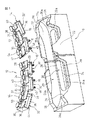
図1〜図3は、本発明の一実施形態によるガイド10と、ガイド10に支持されるファスナー部材12とを示す。ファスナー部材12は、成形主体の立体的表面に追従可能な可撓性を有する対面係合式のファスナー部材であり、後述するように、帯状の基部14と、基部14の一面16に所定間隔で立設される複数の係合要素18とを備える。
【0012】
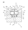
ガイド10は、ファスナー部材12を所望長さに渡って支持する棒状ブロック体であり、ファスナー部材12の基部14及び複数の係合要素18を収容可能な直線溝状の受容部20を画成する一対の側壁部22及び底部24を備える。一対の側壁部22は、底部24を挟んで互いに平行に離間して配置され、各側壁部22に、ガイド10の全長に渡って一様な間隔で互いに対向する側面22aが形成される。底部24は、それら側壁部22の間で受容部20の延長方向両端領域に設けられる一対の封止部26と、両側壁部22にそれぞれ隣接してガイド10の長手方向へ延設される一対の補助支持部28とを備え、それら封止部26と補助支持部28との間に、受容部20の一部を構成する溝部30が形成される。したがって底部24には、両側壁部22の側面22aに略直交する段付きの底面24aが形成される。
【0013】
一対の側壁部22の側面22aの間隔は、支持対象のファスナー部材12の基部14の横断方向寸法と略同一に形成される。したがって各側壁部22の側面22aは、受容部20に受容されたファスナー部材12の基部14の長手方向へ延びる側縁に密接する。受容部20の一部を構成する溝部30には、ファスナー部材12の複数の係合要素18が収容される。底部24の底面24aは、封止部26及び補助支持部28のそれぞれにおいて、受容部20に受容されたファスナー部材12の基部14の一面16の一部分に当接される。このようにしてファスナー部材12は、基部14がガイド10の受容部20に嵌め込まれて、摩擦力により所定の姿勢で保持される。
【0014】
ガイド10の底部24に設けた一対の封止部26は、封止面26aをそれぞれに備える。それら封止面26aは、受容部20の延長方向両端に向けて、受容部20の深さを実質的に漸減させるように、凹状に湾曲して延びる。各封止面26aは、受容部20に受容されたファスナー部材12の基部14の一面16の少なくとも一部分に密接する。その結果、後述するように、ガイド10にファスナー部材12を支持した状態で成形主体を成形する際に、溝部30内への溶融材料の浸入が防止される。なお、好ましくは各封止部26の封止面26aは、一対の補助支持部28の上面に段差無く円滑に接続される。
【0015】
上記構成を有するガイド10は、例えばアルミニウム、アルミニウム合金、鉄等の金属棒状素材から切削加工により一体的に作製される。この場合、例えばNCフライス盤に装着したティースローカッターにより、所定のプログラムに従って、受容部20を切削加工することができる。しかしながらガイド10は、これに限らず他の様々な公知の方法により作製できる。また、ガイド10を、ゴム系材料又はプラスチック材料から、各種成形方法により作製することもできる。
【0016】
ガイド10の底部24に補助的に設けた一対の補助支持部28は、図示実施形態では長手方向に連続的に形成されている。また、補助支持部28によって受容部20内に画成される溝部30の深さは、ファスナー部材12の複数の係合要素18の基部12からの突出長さよりも大きく設定される。この構成によれば、受容部20にファスナー部材12を収容したときに、複数の係合要素18が溝部30内の底面24aに接触することを防止しつつ、各補助支持部28がファスナー部材12の基部14を所望姿勢に確実に支持するとともに、基部14の長手方向に渡ってその一面16に連続的に密着するので、溝部30への成形主体の溶融材料の浸入を一層効果的に防止することができる。なお、ファスナー部材12の基部14を所望姿勢に支持する観点では、各補助支持部28を、ガイド10の長手方向に間隔をあけて所望位置に分散的に配設する構成とすることもできる。或いは、そのような基部14の支持が必要無い場合には、補助支持部28を省略することもできる。
【0017】
ガイド10に支持される一例としてのファスナー部材12は、その帯状の基部14が、長手方向へ互いに離間して整列配置される複数の箱状部32と、それら箱状部32を相互に一体的に連接する複数の連接部34とを備えて構成される。各箱状部32は、互いに略平行に延びる平坦な上板部分36及び下板部分38と、それらを互いに接続する一対の側板部分39とを備える。複数の箱状部32の上板部分36は、それぞれに複数の係合要素18を配置する基部14の一面16を構成し、複数の箱状部32の下板部分38は、複数の連接部34と共に、基部14の他面40を構成する。各箱状部32の上板部分36、下板部分38及び両側板部分39の間には、長手方向へ延びる縦板部分42が設けられ、それら板部分36、38、39、42によって、各箱状部32内に一対の空洞44が画成される。
【0018】
複数の係合要素18の各々は、各箱状部32の上板部分36から略直立状に突出する脚部46と、脚部46の先端近傍にて側方へ突設される複数の係合片48とを備える。したがってファスナー部材12では、複数の係合要素18がそれぞれの先端の係合片48にて、係合相手部材の対応の係合要素に係合する。なお、基部14の長手方向両端の箱状部32′には、係合要素18が形成されない。
【0019】
各箱状部32の下板部分38には、その長手方向略中央に、横断方向へ延びるスリット50が形成される。さらに下板部分38には、スリット50を横断して長手方向へ延びるリブ52が、基部14の全体に渡って他面40に突設される。リブ52には、各箱状部32に対して2個ずつ、下板部分38に略平行に延びる薄板状のアンカー54が形成される。リブ52及びアンカー54は、後述するインサート成形工程を経て成形主体に埋め込まれる連結要素であり、成形主体に対するファスナー部材12の機械的連結部分を構成する。
【0020】
このような構成を有するファスナー部材12は、各箱状部32の空洞44による応力分散作用により、基部14を水平方向すなわち一面16に平行な方向へ全体として比較的容易に撓曲することができる。また、薄肉の各連接部34の蝶番作用により、基部14を鉛直方向すなわち一面16に直交する方向へ全体として比較的容易に撓曲することができる。このようにファスナー部材12は、基部14を水平方向及び鉛直方向のいずれにも容易に撓曲できるので、多様な立体的表面を有する物体の所望の表面部位に、基部14を三次元的に正確に追従させて設置することができる。したがってガイド10も、ファスナー部材12を所望の三次元的撓曲形状に支持すべく、多様な撓曲形状を有することができる。なお、好ましくはファスナー部材12は、ナイロン、ポリエステル、ポリプロピレン等の樹脂材料から一体的に形成される。
【0021】
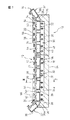
ガイド10は、上記構成を有するファスナー部材12を所定の姿勢に支持する。このとき図2に示すように、ファスナー部材12の基部14の長手方向両端の箱状部32′は、隣接する箱状部32との間の連接部34が弾性的に撓曲した状態で、ガイド10の一対の封止部26にそれぞれ載置され、ガイド10の長手方向両端から外方へはみ出して支持される。ここで、各封止部26に各箱状部32′の上板部分36を容易に載置できるように、上記したように各箱状部32′には係合要素18が設けられていない。ファスナー部材12の基部14の他の箱状部32は、係合要素18をガイド10の溝部30に挿入して、受容部20に嵌め込まれる。
【0022】
この状態で、ファスナー部材12の長手方向両端の箱状部32′の各々は、上板部分36及び下板部分38とガイド10の両側壁部22との間の摩擦力、並びに隣接する箱状部32との間の連接部34の弾性復元力により、上板部分36の表面すなわち基部14の一面16が、各封止部26の凹状に湾曲する封止面26aに実質的に密着して、溝部30をシールすることができる。また、ファスナー部材12の基部14の、ガイド10の受容部20に収容される部分では、各箱状部32の上板部分36、下板部分38及び両側板部分39の各々の両縁、並びに各箱状部32を連接する連接部34の両縁が、ガイド10の両側壁部22の側面22aに密着する。このようにしてガイド10は、溝部30の液密性を確保しながら、ファスナー部材12の基部14を所定の姿勢に保持することができる。
【0023】
ガイド10では、各側壁部22の側面22aの、隣接する各補助支持部28の上面からの高さは、ファスナー部材12の基部14の厚みすなわち一面16と他面40との間の距離と同一であるか、又は僅かに大きくなっていることが望ましい。この構成によれば、ファスナー部材12の基部14がガイド10の受容部20に確実に、すなわち基部14の一面16が一対の補助支持部28の上面に接触した状態に嵌め込まれていることを、目視又は触感により容易に確認できる。ただし、ガイド10の各側壁部22の側面22aがファスナー部材12の基部14の他面40から突出し過ぎると、後述する成形主体の成形時に溶融材料の円滑な流動を阻害する懸念がある。したがって、ガイド10の各側壁部22の側面22aの高さとファスナー部材12の基部14の厚みとの差は、1mm程度であることが好ましい。
【0024】
また、図示実施形態のガイド10では、各側壁部22の長手方向両端の所望長さ部分に沿って、側面22aの高さ方向へ延長される一対の案内部56が設けられる。それら案内部56は、各側壁部22の側面22aに隣接する側にテーパ面56aを備える。ファスナー部材12をガイド10の受容部20に嵌め込む際に、各案内部56はテーパ面56aの作用により、ファスナー部材12の基部14を受容部20へ導き、以てファスナー部材12の嵌め込みを容易にすることができる。
【0025】
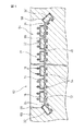
図4は、上記したガイド10を用いて、インサート成形工程によりファスナー部材12を成形主体60に一体的に取り付けてなる成形物品62を示す。成形物品62の成形主体60は、例えば乗物用座席の芯材を構成する。インサート成形工程に際しては、ファスナー部材12は、図2に示す形態でガイド10に装着される。このようにして作製された成形物品62は、成形主体60の表面の所定位置に、ファスナー部材12を固定的に配置する凹部64を備える。凹部64は、成形主体60の成形時にガイド10が占有していた空間に相当し、ガイド10の両側壁部22の上端面に対応して形成された底壁66と、ガイド10の両側壁部22及び底部24の長手方向両端面に対応して形成された対向側壁68とを有する。
【0026】
ファスナー部材12は、その基部14の一面16に形成した複数の係合要素18が、凹部64内に露出して配置され、また他面40に形成したリブ52及び複数のアンカー54が、成形主体60に埋設される。さらにファスナー部材12は、基部14の長手方向両端の箱状部32′が、隣接する箱状部32との間の連接部34を基部14の一面16側を凸に撓曲させた状態で、成形主体60に少なくとも部分的に埋設される。このとき、前述したガイド10の両封止部26とファスナー部材12の両箱状部32′との相対位置関係により、両箱状部32′は、成形主体60の凹部64の底壁66と対向側壁68との交差部位すなわち角部に斜めに食い込むようにして、成形主体60に埋設されることになる。
【0027】
このように、ファスナー部材12がその長手方向両端部で、成形主体60の凹部64の底壁66と対向側壁68との両交差部位に斜めに食い込むことにより、成形主体60の凹部64が補強される。つまり、例えば成形された成形物品62から型及びガイド10を脱離する際に、成形主体60を動かしてファスナー部材12をガイド10から抜き取ろうとすると、通常は成形主体60の凹部64の底壁66と対向側壁68とを互いに引き離すような応力が、それら壁66、68の交差部位に集中して加わる。しかし、成形物品62においては、ファスナー部材12がその長手方向両端部で、成形主体60の凹部64の底壁66と対向側壁68との間に応力集中により生じ得る亀裂に実質的に対応する方向へ食い込んで固定されるので、このような応力集中に抗して各壁66、68を補強し、それらの交差部位に亀裂等の損傷が生じることを効果的に防止するのである。なお、ファスナー部材12の長手方向両端部分によるこのような補強作用は、完成品としての成形物品62の使用中にも格別の効果を発揮するものである。
【0028】
次に、ガイド10を用いて上記成形物品62を製造するインサート成形工程を説明する。
まず、ガイド10を、その受容部20を成形主体60の型(図示せず)の空洞部に向けて、型の成形面にパテ等の固定手段を用いて固定する。なお、この固定手段としては、ボルトや磁石等の他の公知手段を用いることができる。特に、磁気的手段を用いてガイド10を型に固定する構成では、以下のファスナー部材12の装着作業を型の外部で行うことができる利点がある。
【0029】
続いて、ファスナー部材12を、その基部14が複数の箱状部32の上板部分36、下板部分38及び両側板部分39並びに複数の連接部34のそれぞれの両縁で、ガイド10の一対の側壁部22の側面22aに密接するとともに、長手方向両端の箱状部32′における基部14の一面16が、ガイド10の一対の封止部26の封止面26aに密接して溝部30をシールするようにして、ガイド10の受容部20に装着する。このとき、ファスナー部材12の複数の係合要素18が、ガイド10の受容部20の溝部30に収容される。また、長手方向両端の箱状部32′は、隣接する箱状部32との間の連接部34が基部14の一面16側を凸に撓曲させた状態で、封止部26に載置される。ここで、箱状部32′には係合要素18が設けられていないので、箱状部32′を封止部26に対して多少の位置ずれを許容しつつ比較的容易に載置できる。
【0030】
この状態で、型を加熱して所定温度に維持した後、型内の空隙部に成形主体60の溶融樹脂材料(例えばポリウレタン等の発泡性液体樹脂材料)を供給する。このとき、ガイド10の一対の側壁部22及び一対の封止部26が、前述したようにファスナー部材12の基部14と協働して、ガイド10の溝部30への溶融樹脂材料の浸入を阻止するように作用する。またファスナー部材12は、溶融樹脂材料が固化するまでの間、ガイド10上に所定姿勢で保持される。さらに、溶融樹脂材料は、ガイド10の両側壁部22によって円滑な流動を阻害されることなく、ファスナー部材12の他面40のリブ52及び複数のアンカー部54の周囲に行き渡り、さらに複数のスリット50から各箱状部32、32′の空洞44に効率良く流入する。すなわち、各箱状部32、32′の空洞44において、空気と溶融樹脂材料との置換が円滑に行われる。
【0031】
その後、型を冷却して溶融樹脂材料を固化させ、成形主体60を成形する。その結果、ファスナー部材12は前述したように、複数の係合要素18を露出させた状態で、成形主体60の表面の所望位置に固定的に連結される。成形主体60の成形後、ファスナー部材12の複数の係合要素18の間には成形主体60の樹脂片が混在せず、したがってファスナー部材12の本来の固着機能は低下しない。また成形主体60の、ファスナー部材12の他面40のリブ52及び複数のアンカー部54を包囲する部分には、成形時の溶融樹脂材料の効率的流動により巣等の欠陥が生じ難くなっており、それによりファスナー部材12が成形主体60に強固に連結される。
【0032】
次いで、成形主体60を動かして変形させつつ、ファスナー部材12をガイド10から脱離するとともに、成形物品62を型から取り出す。このとき前述したように、ファスナー部材12がその長手方向両端部で、成形主体60の凹部64の底壁66と対向側壁68との両交差部位に斜めに食い込んで各壁66、68を補強するので、ガイド10からファスナー部材12を容易に脱離できる。それに伴い、ガイド10からの脱離時にファスナー部材12のアンカー部54が成形主体60に加える応力も減少する。したがって、成形主体60を傷つけることなく、成形物品62を型及びガイド10から容易に取り外すことができる。
【0033】
ところで、上記構成を有するガイド10は、受容部20の外部へさらに長く延長されるファスナー部材12を支持することもできる。この場合、例えば図5に示すように、ファスナー部材12はその基部14の長手方向両端の箱状部32に隣接する箱状部32″(一方の箱状部32″のみ図示)が、係合要素18を備えずに形成される。このような構成によれば、成形物品62の成形主体60に、ファスナー部材12の基部14の長手方向両端の箱状部32が、係合要素18及び連結要素52、54を含む全体として、成形主体60に埋設されて連結機能を発揮する。その結果、ファスナー部材12と成形主体60との接合が一層強化される。しかもこの場合、ファスナー部材12の長手方向両端の箱状部32が成形中に撓んでしまっても、隣接する箱状部32″が上記したように確実に凹部64を補強する。なおこの構成においても、長手方向両端の箱状部32の係合要素18を省略できることは言うまでもない。
【0034】
さらにガイド10によれば、封止部26の封止面26aとファスナー部材12の基部14との間で所望のシール作用が得られる限り、ガイド10と実質的に同一か、より短かい長さのファスナー部材12を支持して、成形主体60に一体的に取り付けることもできる。この場合にも、ガイド10の上方へはみ出すファスナー部材12の長手方向両端の一部分が成形主体60に埋設されて、上記した補強効果を発揮する。
【0035】
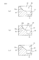
以上、本発明の好適な実施形態を説明したが、本発明はこれに限定されず、様々な変形又は修正を施すことができる。例えば図6に示すように、ガイド10の封止部26は、一対の側壁部22の間で、受容部20の延長方向両端に向けて受容部20の深さを実質的に漸減させることができる様々な表面形状を有する封止面26aを備えることができる。例として、図6(a)は、円筒面状の封止面26aを示す。この場合、封止面26aの曲率半径は特に限定されないが、一般的なファスナー部材12の基部14の撓曲容易性を考慮すれば、10mm〜70mmの曲率半径を有することが好ましい。また図6(b)は、平面部分26bと曲面部分26cとを円滑に接続して形成した封止面26aを示す。また図6(c)は、傾斜平面からなる封止面26aを示す。さらに、図示しないが、階段状や凹凸状に延びる封止面26aを有することもできる。いずれの場合も、ガイド10の長手方向に沿った封止面26aの長さは、10mm〜50mmであることが好ましい。
【0036】
ガイド10の一対の側壁部22に設けられる案内部56は、図7に示すように、各側壁部22の長手方向に互いに離間して複数(図では2個)の案内部56を形成することもできる。しかしこの場合、前述したように、成形主体60の溶融樹脂材料の円滑な流動を阻害しないように設けることが要求される。
【0037】
さらに、ガイド10を適用可能なファスナー部材は、少なくとも基部が可撓性を有するものであれば、前述したファスナー部材12以外の構成を有するファスナー部材を適用できる。例えば、特開平9−224720号公報、特開平8−140713号公報等に開示されているファスナー部材を、本発明に係るガイドに適用して、成形物品を製造することもできる。
【0038】
本発明の好適な実施の形態の特徴を、以下に整理して列記する。
ガイドの一対の側壁部は、ガイドの全長に渡って一様な間隔で互いに対向する側面をそれぞれに有する。それら側面は、ファスナー部材の基部の両縁に密着できるようになっている。
ガイドの両側壁部にそれぞれ隣接して、ガイドの長手方向へ延設される一対の補助支持部をさらに備えることができる。それら補助支持部は、封止部と協働して、受容部内に、ファスナー部材の係合要素を収容可能な溝部を形成する。この場合、各補助支持部の上面は、各封止部の封止面に段差無く円滑に接続されることが好ましい。
各側壁部の側面の、隣接する各補助支持部の上面からの高さは、支持対象のファスナー部材の基部の厚みと同一であるか、又は僅かに大きくなっていることが望ましい。
各側壁部の所望長さ部分に沿って、側面の高さ方向へ延長される案内部を設けることができる。案内部には、各側壁部の側面に隣接する側にテーパ面を形成できる。
【0039】
【発明の効果】
以上の説明から明らかなように、本発明によれば、ファスナー部材を成形主体に一体的に取り付けるためのインサート成形工程で使用されるガイドにおいて、ファスナー部材をガイドに容易に装着することができる。また成形主体の成形時に、ファスナー部材の係合要素を収容したガイドの受容部への液体材料の浸入を確実に防止することができる。しかも成形後には、成形主体を損傷することなくガイドから容易に取り外すことが可能になる。
さらに本発明によれば、ファスナー部材を成形主体に一体的に取り付けてなる成形物品において、ファスナー部材を固定した成形主体の凹部における亀裂等の損傷を効果的に防止することが可能になる。
【図面の簡単な説明】
【図1】本発明の一実施形態によるガイドを、支持対象のファスナー部材と共に示す部分切欠き斜視図である。
【図2】図1のガイドを、ファスナー部材を装着した状態で示す図で、図3の線II−IIに沿った縦断面図である。
【図3】図1のガイドを、ファスナー部材を装着した状態で示す図で、図2の線 III−III に沿った縦断面図である。
【図4】図1のガイドを用いてファスナー部材を成形主体に一体的に取り付けてなる成形物品の主要部分を示す縦断面図である。
【図5】図1のガイドの他の使用形態を示す図で、図2に対応した縦断面図である。
【図6】図1のガイドにおける封止部の封止面の幾つかの変形例を(a)〜(c)に示す部分拡大縦断面図である。
【図7】図1のガイドにおける側壁部の案内部の変形例を示す部分正面図である。
【符号の説明】
10…ガイド
12…ファスナー部材
14…基部
16…一面
18…係合要素
20…受容部
22…側壁部
22a…側面
26…封止部
26a…封止面
28…補助支持部
30…溝部
32、32′、32″…箱状部
34…連接部
40…他面
52…リブ
54…アンカー部
60…成形主体
62…成形物品
64…凹部[0001]
BACKGROUND OF THE INVENTION
The present invention relates to a guide used for integrally attaching a fastener member to a molding main body..
[0002]
[Prior art]
A cushioning core material made of, for example, a foamed resin material, such as a vehicle seat, office or home chair, mattress, etc., and a flexible covering made of fabric or leather covering the surface of the core material In an article provided with a material, a face-engagement type fastener member (so-called surface fastener) in which a plurality of engagement elements are arranged on one surface of a base portion in order to firmly and securely attach a covering material to a core material. It is known to use (see, for example, JP-A-9-224720).
[0003]
Especially for articles such as seats and chairs, it is desirable to provide users with a high level of comfort. Therefore, as a fixing means for attaching the covering material to the core material, the core along the seam of the covering material is used. There is a tendency to use a fastener member having an elongated band shape that can be disposed in a groove provided on the material surface. In order to fix such a band-shaped fastener member at a desired position on the surface of the core material with the engaging elements exposed, the fastener member is disposed as an insert in the mold of the core material that is the molding main body, An insert molding method in which the fastener member is fixed to the core material at the same time as the core material is formed is advantageously implemented. For example, Japanese Patent No. 2,704,859 discloses a guide for supporting a fastener member in a mold that is a main molding body in such an insert molding method. The guide includes a groove portion that accommodates the fastener member, and is provided with an isolation member that is inserted between the plurality of engaging elements of the fastener member in the vicinity of both ends of the groove portion. The isolation member is for preventing the liquid foam material from entering the inside of the groove during molding of the core material.
[0004]
[Problems to be solved by the invention]
In the guide disclosed in Japanese Patent No. 2,704,859, the isolation member for preventing the liquid material from entering the groove is inserted between the plurality of engaging elements of the fastener member. Is necessarily formed thin. Therefore, even if the base portion of the fastener member attached to the guide is slightly deformed, there is a concern that a gap is generated between the isolation member and the base portion of the fastener member, and the sealing effect on the liquid material is lowered. If the molding main body is molded in a state where the liquid material has entered the groove portion of the guide, resin pieces of the molding main body are mixed between the plurality of engaging elements of the fastener member. There is a risk that the function will deteriorate. Furthermore, there is a concern that the engaging element of the fastener member may be damaged by the insertion of the isolation member. It is generally difficult to attach the fastener member to the guide while avoiding such damage, and skill is required.
[0005]
Further, when the molding main body is molded using the above-described guide, a concave portion having a shape corresponding to the outer shape of the guide is formed on the surface of the molding main body, and the fastener member is fixed in the concave portion. That is, the concave portion has a bottom wall formed corresponding to the upper end surface of the guide and two sets of opposing side walls formed corresponding to the outer end surface of the guide. When detaching the molding main body from the mold and the guide, when trying to move the molding main body and pull out the fastener member from the guide, a stress that normally separates the bottom wall and the opposite side wall of the concave portion of the molding main body from each other, It concentrates on the intersection part of those walls, that is, the corner. Due to such stress concentration, the molding body may cause damage such as cracks at both intersections between the bottom wall of the recess and in particular a pair of opposing side walls corresponding to the transverse direction of the guide. This problem of stress concentration also occurs during use after product completion.
[0006]
As described above, the guide described in Japanese Patent No. 270459 has difficulty in preventing damage due to stress concentration in the concave portion of the molding main body. Further, it is also disclosed that the fastener member protrudes from both ends in the longitudinal direction of the guide and is supported, but in this case, the protruding portion of the fastener member bends during molding and faces the bottom wall of the concave portion of the molding main body. There is a tendency to be displaced from the direction of stress concentrated at the intersection with the side wall. Therefore, it is still difficult to prevent damage due to stress concentration in the concave portion of the molding main body.
[0007]
It is an object of the present invention to easily attach a fastener member in a guide used in an insert molding process for integrally attaching a fastener member to a molding main body, and at the time of molding the molding main body, It is an object of the present invention to provide a guide that can reliably prevent the liquid material from entering the receiving portion accommodated therein and can be easily removed after the molding without damaging the molding body.
[0009]
[Means for Solving the Problems]
In order to achieve the above object, the invention according to claim 1 is installed in a mold of a molding main body in order to integrally attach a fastener member having an engagement element provided on one surface of a base to the molding main body. The guide includes a pair of side wall portions defining a base portion of the fastener member and a receiving portion capable of accommodating the engaging element, and a sealing portion provided between the side wall portions in both end regions in the extending direction of the receiving portion, The sealing portion has a sealing surface that can be in close contact with the base portion of the fastener member between the pair of side wall portions, and the sealing surface substantially reduces the depth of the receiving portion toward both ends in the extending direction of the receiving portion. A guide characterized by having a tapering shape is provided.
[0011]
DETAILED DESCRIPTION OF THE INVENTION
Embodiments of the present invention will be described below in detail with reference to the accompanying drawings. In the drawings, the same or similar components are denoted by common reference numerals.
1 to 3 show a
[0012]
The
[0013]
The distance between the
[0014]
Each of the pair of sealing
[0015]
The
[0016]
In the illustrated embodiment, the pair of
[0017]
The
[0018]
Each of the plurality of
[0019]
In the
[0020]
The
[0021]
The
[0022]
In this state, each of the box-
[0023]
In the
[0024]
In the
[0025]
FIG. 4 shows a molded
[0026]
The
[0027]
Thus, the recess 64 of the
[0028]
Next, an insert molding process for manufacturing the molded
First, the
[0029]
Subsequently, the
[0030]
In this state, the mold is heated and maintained at a predetermined temperature, and then a molten resin material (for example, a foamable liquid resin material such as polyurethane) of the
[0031]
Thereafter, the mold is cooled to solidify the molten resin material, and the molding
[0032]
Next, while moving and deforming the molding
[0033]
By the way, the
[0034]
Further, according to the
[0035]
As mentioned above, although preferred embodiment of this invention was described, this invention is not limited to this, A various deformation | transformation or correction can be given. For example, as shown in FIG. 6, the sealing
[0036]
As shown in FIG. 7, the
[0037]
Furthermore, the fastener member which can apply the
[0038]
The features of preferred embodiments of the present invention are summarized and listed below.
Each of the pair of side wall portions of the guide has side surfaces facing each other at a uniform interval over the entire length of the guide. These side surfaces can come into close contact with both edges of the base portion of the fastener member.
A pair of auxiliary support portions extending in the longitudinal direction of the guide may be further provided adjacent to both side wall portions of the guide. The auxiliary support portions cooperate with the sealing portion to form a groove portion capable of accommodating the engaging element of the fastener member in the receiving portion. In this case, it is preferable that the upper surface of each auxiliary support part is smoothly connected to the sealing surface of each sealing part without a step.
It is desirable that the height of the side surface of each side wall portion from the top surface of each adjacent auxiliary support portion is the same as or slightly larger than the thickness of the base portion of the fastener member to be supported.
A guide portion extending in the height direction of the side surface can be provided along a desired length portion of each side wall portion. A taper surface can be formed in the guide part on the side adjacent to the side surface of each side wall part.
[0039]
【The invention's effect】
As apparent from the above description, according to the present invention, in the guide used in the insert molding process for integrally attaching the fastener member to the molding main body, the fastener member can be easily attached to the guide. Further, when the molding main body is molded, it is possible to reliably prevent the liquid material from entering the receiving portion of the guide that accommodates the engaging element of the fastener member. Moreover, after molding, it can be easily removed from the guide without damaging the molding body.
Furthermore, according to the present invention, in a molded article in which the fastener member is integrally attached to the molding body, it is possible to effectively prevent damage such as cracks in the concave portion of the molding body to which the fastener member is fixed.
[Brief description of the drawings]
FIG. 1 is a partially cutaway perspective view showing a guide according to an embodiment of the present invention together with a fastener member to be supported.
2 is a view showing the guide of FIG. 1 in a state where a fastener member is mounted, and is a longitudinal sectional view taken along line II-II of FIG.
3 is a view showing the guide of FIG. 1 in a state where a fastener member is mounted, and is a longitudinal sectional view taken along line III-III of FIG.
4 is a longitudinal sectional view showing a main part of a molded article obtained by integrally attaching a fastener member to a molding main body using the guide of FIG.
5 is a view showing another usage pattern of the guide of FIG. 1, and is a longitudinal sectional view corresponding to FIG.
6 is a partially enlarged longitudinal sectional view showing several modified examples of the sealing surface of the sealing portion in the guide of FIG. 1 in (a) to (c).
7 is a partial front view showing a modification of the guide portion of the side wall portion in the guide of FIG. 1. FIG.
[Explanation of symbols]
10 ... Guide
12 ... Fastener member
14 ... Base
16 ... one side
18 ... engaging element
20 ... receiving part
22 ... side wall
22a ... Side
26: Sealing part
26a ... sealing surface
28 ... Auxiliary support part
30 ... Groove
32, 32 ', 32 "... Box
34 ... articulated part
40 ... other side
52 ... Ribs
54 ... Anchor part
60 ... Molding subject
62. Molded article
64 ... recess
Claims (1)
前記ファスナー部材の前記基部及び前記係合要素を収容可能な受容部を画成する一対の側壁部と、それら側壁部の間で該受容部の延長方向両端領域に設けられる封止部とを備え、
前記封止部が、前記一対の側壁部の間で前記ファスナー部材の前記基部に密接可能な封止面を有し、該封止面が、該受容部の延長方向両端に向けて該受容部の深さを実質的に漸減させる形状を有すること、
を特徴とするガイド。In order to integrally attach a fastener member having an engagement element provided on one surface of a base to a molding main body, in a guide installed in a mold of the molding main body,
A pair of side wall portions defining a receiving portion capable of accommodating the base portion and the engaging element of the fastener member, and a sealing portion provided between the side wall portions in both end regions in the extending direction of the receiving portion; ,
The sealing portion has a sealing surface that can be in close contact with the base portion of the fastener member between the pair of side wall portions, and the sealing surface faces the both ends of the receiving portion in the extending direction. Having a shape that substantially reduces the depth of
A featured guide.
Priority Applications (1)
| Application Number | Priority Date | Filing Date | Title |
|---|---|---|---|
| JP12442899A JP4222682B2 (en) | 1999-04-30 | 1999-04-30 | guide |
Applications Claiming Priority (1)
| Application Number | Priority Date | Filing Date | Title |
|---|---|---|---|
| JP12442899A JP4222682B2 (en) | 1999-04-30 | 1999-04-30 | guide |
Publications (2)
| Publication Number | Publication Date |
|---|---|
| JP2000317945A JP2000317945A (en) | 2000-11-21 |
| JP4222682B2 true JP4222682B2 (en) | 2009-02-12 |
Family
ID=14885253
Family Applications (1)
| Application Number | Title | Priority Date | Filing Date |
|---|---|---|---|
| JP12442899A Expired - Fee Related JP4222682B2 (en) | 1999-04-30 | 1999-04-30 | guide |
Country Status (1)
| Country | Link |
|---|---|
| JP (1) | JP4222682B2 (en) |
Families Citing this family (2)
| Publication number | Priority date | Publication date | Assignee | Title |
|---|---|---|---|---|
| JP2002165617A (en) * | 2000-11-28 | 2002-06-11 | Three M Innovative Properties Co | Fastener positioning member and fastener with positioning function |
| JP3973475B2 (en) | 2002-04-08 | 2007-09-12 | スリーエム イノベイティブ プロパティズ カンパニー | Strip member support guide |
-
1999
- 1999-04-30 JP JP12442899A patent/JP4222682B2/en not_active Expired - Fee Related
Also Published As
| Publication number | Publication date |
|---|---|
| JP2000317945A (en) | 2000-11-21 |
Similar Documents
| Publication | Publication Date | Title |
|---|---|---|
| KR101833156B1 (en) | Molded hook and loop fastener | |
| JP4222682B2 (en) | guide | |
| JP7706827B2 (en) | Vehicle seat pad and manufacturing method thereof | |
| JP5088816B2 (en) | Hook fastener, cushion pad provided with the hook fastener, and mold | |
| JP7292045B2 (en) | seat pad and mold | |
| JP4936378B2 (en) | Cushion pad mold and cushion pad manufacturing method | |
| JP5098297B2 (en) | Seat pad and seat | |
| JPH0418459Y2 (en) | ||
| JPH06254268A (en) | Urethane foam cushioning member and production thereof | |
| JP3973475B2 (en) | Strip member support guide | |
| JP3939155B2 (en) | Embedded mounting fastener | |
| JPH0691662A (en) | Surface fastener integral foamed molded form and its manufacture | |
| JP2002337149A (en) | Guide and mold | |
| JPH0327781Y2 (en) | ||
| JP7490849B2 (en) | Seat pad for vehicle | |
| JP3621201B2 (en) | Suspended surface fastener integrated foam type | |
| JP4745781B2 (en) | Seat pad, mold and manufacturing method thereof | |
| JP2001310341A (en) | Guide and mold | |
| JP2015119810A (en) | Manufacturing method of sheet pad and molding die | |
| JP2004236957A (en) | Belt-shaped fastener | |
| JPH11300749A (en) | Holder for holding fastener member | |
| JP2001017279A (en) | Foam-molded body incorporating fastening member and foam molding mold therefor | |
| JP7166041B2 (en) | Vehicle seat pad and manufacturing method thereof | |
| JPH0195012A (en) | Manufacture of foamed material molded product with surface fastener | |
| JP2006192739A (en) | Fastener support member and method for manufacturing foam molded article |
Legal Events
| Date | Code | Title | Description |
|---|---|---|---|
| A621 | Written request for application examination |
Free format text: JAPANESE INTERMEDIATE CODE: A621 Effective date: 20060105 |
|
| A977 | Report on retrieval |
Free format text: JAPANESE INTERMEDIATE CODE: A971007 Effective date: 20080620 |
|
| A131 | Notification of reasons for refusal |
Free format text: JAPANESE INTERMEDIATE CODE: A132 Effective date: 20080624 |
|
| A521 | Written amendment |
Free format text: JAPANESE INTERMEDIATE CODE: A523 Effective date: 20080924 |
|
| TRDD | Decision of grant or rejection written | ||
| A01 | Written decision to grant a patent or to grant a registration (utility model) |
Free format text: JAPANESE INTERMEDIATE CODE: A01 Effective date: 20081021 |
|
| A01 | Written decision to grant a patent or to grant a registration (utility model) |
Free format text: JAPANESE INTERMEDIATE CODE: A01 |
|
| A61 | First payment of annual fees (during grant procedure) |
Free format text: JAPANESE INTERMEDIATE CODE: A61 Effective date: 20081118 |
|
| R150 | Certificate of patent or registration of utility model |
Free format text: JAPANESE INTERMEDIATE CODE: R150 |
|
| FPAY | Renewal fee payment (event date is renewal date of database) |
Free format text: PAYMENT UNTIL: 20111128 Year of fee payment: 3 |
|
| LAPS | Cancellation because of no payment of annual fees |