JP4217162B2 - Game machine - Google Patents
Game machine Download PDFInfo
- Publication number
- JP4217162B2 JP4217162B2 JP2004000698A JP2004000698A JP4217162B2 JP 4217162 B2 JP4217162 B2 JP 4217162B2 JP 2004000698 A JP2004000698 A JP 2004000698A JP 2004000698 A JP2004000698 A JP 2004000698A JP 4217162 B2 JP4217162 B2 JP 4217162B2
- Authority
- JP
- Japan
- Prior art keywords
- display
- identification information
- image
- image data
- variation
- Prior art date
- Legal status (The legal status is an assumption and is not a legal conclusion. Google has not performed a legal analysis and makes no representation as to the accuracy of the status listed.)
- Expired - Fee Related
Links
Images


Description
本発明は、パチンコ遊技機、スロットマシン、アーケードゲーム装置、家庭用ゲーム装置等を含む遊技機に関し、特に、識別情報の変動表示を用いて遊技を行う遊技機に関する。 The present invention relates to a gaming machine including a pachinko gaming machine, a slot machine, an arcade game device, a home-use game device, and the like, and more particularly, to a gaming machine that performs a game using a variation display of identification information.
パチンコ遊技機等の遊技機においては、液晶表示装置(以下LCD:Liquid Crystal Display)等の表示装置上に所定の識別情報(以下、表示図柄)を更新表示させることで変動表示を行い、その表示結果により所定の遊技価値を付与するか否かを決定する、いわゆる可変表示ゲームによって遊技興趣を高めたものが数多く提供されている。 In gaming machines such as pachinko machines, variable display is performed by updating and displaying predetermined identification information (hereinafter referred to as display symbols) on a display device such as a liquid crystal display (hereinafter referred to as LCD: Liquid Crystal Display). There are provided a number of games that are enhanced by a so-called variable display game that determines whether or not to give a predetermined game value based on the result.
可変表示ゲームには、前述した表示装置を画像表示装置として用いることにより行うもの(以下、特図ゲーム)がある。特図ゲームは、始動入賞口を通過する遊技球の検出(変動実行条件の成立)に伴って表示図柄の更新表示を行い、表示図柄の更新表示が完全に停止した際の停止図柄の態様が特定表示態様となっている場合を「大当り」とするゲームである。特図ゲームにおいて「大当り」となると、大入賞口またはアタッカと呼ばれる特別電動役物を開放状態とし、遊技者に対して遊技球の入賞が極めて容易となる状態を一定時間継続的に提供する。この状態を「特定遊技状態」という。 Some variable display games are played by using the above-described display device as an image display device (hereinafter referred to as a special game). In the special figure game, when the game ball passing through the start winning opening is detected (variation execution condition is established), the display symbol is updated, and the display symbol update state is completely stopped when the display symbol update display is completely stopped. The game is a “big hit” when the specific display mode is set. When a “big hit” is made in a special game, a special electric combination called a big prize opening or an attacker is opened, and a state in which a game ball can be won very easily is provided to a player for a certain period of time. This state is referred to as a “specific game state”.
遊技者は、この特定遊技状態を得ることを目標として遊技を行う。従って、遊技者の注目は、識別情報の変動表示とその変動結果の表示に集中することになる。 The player plays a game with the goal of obtaining this specific gaming state. Therefore, the player's attention will be concentrated on the display of the variation of the identification information and the display of the variation result.
この識別情報の変動表示及び変動結果の表示を変化に富んだものとして興趣性を高め、さらに、表示処理の効率化を図るため、様々な提案がなされている。 Various proposals have been made in order to enhance the interest and make the display process more efficient by making the display of the variation of the identification information and the display of the variation result rich.
例えば、特許文献1は、図柄変動領域に表示する図柄の種類、大きさ、位置、向きを指定して図柄を表示させることにより、図柄を変動表示させることを開示する。
従来は、図柄配列の種類や大きさなどを指定することにより図柄の変動を制御する。このため、図柄の大きさや向きが変わる程度の表示上の変化が与えられる程度であり、興趣性に乏しいものであった。 Conventionally, the variation of the symbol is controlled by designating the type and size of the symbol array. For this reason, the change in the display is such that the size and orientation of the symbol is changed, and it is not interesting.
また、表示図柄の変化を大きなものとするため、図柄配列と変動パターン毎に画像データを記憶することも考えられるが、表示態様の異なる画像データ(アニメ表示用の画像データ)を図柄配列と変動パターン毎に記憶するとデータ量が大きくなり、制御も複雑になるという問題が発生する。 In addition, in order to make the change of the display symbol large, it may be possible to store image data for each symbol arrangement and variation pattern, but image data with different display mode (image data for animation display) varies with the symbol arrangement. If each pattern is stored, the amount of data becomes large and the control becomes complicated.
また、パチンコ遊技機等の場合、興趣を高めるため識別情報に様々なキャラクタ(動物、有体物等)の画像を付加することが行われる。しかし、従来では、このキャラクタの実世界での特徴、例えば、重さ、大きさ等に合わせた表示制御が行われておらず、キャラクタが遊技者に与える実世界での印象と画面上に表示されるキャラクタの印象との間に乖離が生じ、キャラクタ画像を使用する効果が十分に引き出せない場合があった。 In the case of a pachinko machine or the like, images of various characters (animals, tangibles, etc.) are added to the identification information in order to enhance interest. However, conventionally, display control according to the character in the real world, such as weight, size, etc., is not performed, and the real-world impression that the character gives to the player and displayed on the screen There is a case where the effect of using the character image cannot be sufficiently obtained due to a deviation from the impression of the character to be displayed.
この発明は、上記実情に鑑みてなされたものであり、制御負担とデータ量を抑えつつ、キャラクタの実世界での特徴に応じた表現を行うことにより、変化に富んだ変動表示が可能な遊技機を提供することを目的とする。 The present invention has been made in view of the above circumstances, and a game capable of a variety of variable display by expressing according to the characteristics of the character in the real world while suppressing the control burden and the amount of data. The purpose is to provide a machine.
上記目的を達成するため、請求項1に記載の遊技機は、
所定の変動開始条件の成立により、各々が識別可能な複数種類の識別情報の変動表示画像を画像表示装置に表示する変動表示制御手段(例えば、主基板11及び表示制御基板12)を備える遊技機であって、
前記複数種類の識別情報のそれぞれを、複数の表示態様で表示するための画像データ(絵のデータ)を記憶する画像データ記憶手段(例えば、画像ROM137)と、
前記画像データ記憶手段に記憶された前記識別情報の種類と配列を特定するための識別情報配列特定情報(特別図柄の番号0〜9)と各識別情報の表示態様の変化(各特別図柄についての図柄の変化)の順番を特定するための画像変化特定情報とを記憶する特定データ記憶手段(例えば、制御ROM134)と、
前記画像表示装置上の識別情報の変動速度と、前記画像表示装置上の該識別情報の変動方向(例えば、上向き、下向き)とを指定する変動速度方向指定手段(CPU133と表示制御データを格納している制御ROM134)と、
前記画像表示装置上で、識別情報を表示するための表示領域の大きさ(サイズ)を特定する表示領域特定手段(例えば、CPU133と制御ROM134)と、
前記特定データ記憶手段に記憶されている前記識別情報配列特定情報により特定される識別情報の配列と前記画像変化特定情報により特定される各識別情報の表示態様の変化の順番とに従って、前記画像データ記憶手段に記憶されている複数種類の識別情報の画像データをマトリクス状に展開する展開手段(例えば、CPU133と制御ROM134)と、
前記変動速度方向指定手段により指定された変動速度及び変動方向と前記表示領域特定手段により特定された大きさとに基づいて、前記展開手段が展開したマトリクス状の画像データ上で、前記画像表示装置上の表示領域内の表示対象の画像データを特定する画像データ特定手段(例えば、CPU133と表示制御データを格納している制御ROM134)と、
識別情報の変動表示結果となる停止識別情報を決定する停止識別情報決定手段(例えば、遊技制御用マイコン100)と、
を備え、
前記変動速度方向指定手段は、
識別情報の変動方向として予め定めた第1の変動方向(例えば、下方向)と前記第1の変動方向の戻り方向となる第2の変動方向(例えば、上方向。ただし、第1の変動方向に対して反対とは限らない)を指定し、
識別情報が第2の変動方向に変動する際の戻り位置を識別情報毎に指定する識別情報毎の戻り位置データ(例えば、図6のテーブル)と、前記停止識別情報決定手段により決定された停止識別情報の停止位置を指定する停止位置データと、を記憶する制御データ記憶手段(例えば、制御ROM134)と、
を備え、
前記変動表示制御手段(例えば、CPU133)は、
前記識別情報の変動表示の開始から、前記第1変動方向に基づいて前記画像データ特定手段により特定された画像データを読み出して表示画像を生成し、前記画像表示装置に出力する処理を順次繰り返すことにより、第1の変動方向へ変動する識別情報の変動表示処理を行い、
前記停止識別情報決定手段により決定された識別情報で停止する際には、前記第2変動方向と停止する識別情報に応じた戻り位置データとに基づいて前記画像データ特定手段により特定される画像データを読み出して表示画像を生成し、前記画像表示装置に出力する処理を順次繰り返すことにより、識別情報に応じた戻り位置まで第2の変動方向へ変動する識別情報の変動表示を行った後、前記第1の変動方向と停止位置データとに基づいて前記画像データ特定手段により特定された画像データを読み出して、表示画像を生成し、前記画像表示装置に出力する処理を順次繰り返すことにより、停止位置まで第1の変動方向へ変動する識別情報の変動表示処理を行う、
ことを特徴とする。
In order to achieve the above object, a gaming machine according to
The establishment of a predetermined variation starting condition, the game to obtain Bei variable display control means for displaying the variable display image identification information of a plurality of types can be identified is each image display device (e.g., a
Image data storage means (for example, image ROM 137) for storing image data (picture data) for displaying each of the plurality of types of identification information in a plurality of display modes;
Identification information arrangement specifying information (
Said storage and changing speed of the identification information on the image display device, the image display fluctuation direction of identification information on the device (e.g., upward, downward) to the display control data and variable speed direction designating means (
On the image display device, a display area specifying means for specifying the size of the display area for displaying the identification information (size) (e.g.,
Accordance with the order of the change of the display mode of the identification information specified by the sequence and the image change certain information in the identification information specified by the identification information sequence identification information stored before Symbol specific data storage means, the image Expansion means (for example,
Based on the fluctuation speed and fluctuation direction designated by the fluctuation speed direction designation means and the size specified by the display area specification means, the matrix display image data developed by the development means on the image display device Image data specifying means (for example, a
Stop the identification information determining means for determining the variable display results Do that stop identification information of the (e.g., a game control microcomputer 100)
With
The fluctuating speed direction specifying means includes
First variation direction determined in advance as a change direction of the identification information (e.g., downward) from the previous SL second variation direction as the first variation direction of the return direction (e.g., upward direction. However, the first specify the limited not) is opposite to the change direction,
Stop identification information and return position data for each identification information for specifying a return position when vary from identification information to the second variation direction (e.g., in Figure 6 table), determined by the stop identification information determination means and stopping position data for designating the stop position of the stop identification information, and the control data storing means for storing (e.g., control ROM 134),
With
The variable display control means (for example, the CPU 133)
Variable display start or these said identification information, said read image data specified to generate a display image by the previous SL image data specifying means based on the first variation Direction, a process of outputting to said image display device By repeating sequentially, the variation display processing of the identification information that varies in the first variation direction is performed,
When stopping at the identification information determined by the stop identification information determination means is specified by the previous SL image data specifying means based on the previous SL return position data corresponding to the second variation Direction and identification information to stop that the image data by reading the display image is generated by sequentially repeating the process of outputting to said image display device, lines Tsu variable display of the identification information that varies the second variation direction to a return position corresponding to the identification information and then reads out the image data specified by the previous SL image data specifying means based on the first variation direction and stopping position data, generates a display image, sequentially a process of outputting to said image display device by repeating performs variable display processing of the identification information that varies to the first variation direction to a stop position,
It is characterized by that.
さらに、請求項2に記載の遊技機では、前記識別情報は、予め対応付けられている第1の表示画像と第2表示画像との2つの表示画像から構成され、前記画像データ記憶手段は、各識別情報について、第1表示画像(例えば、特別図柄としての数字)の画像データと、第2表示画像(例えば、特別図柄としてのキャラクタ画像)の画像データとを記憶し、
前記展開手段は、各前記識別情報について、変動表示の開始から変動の停止までの間で、所定の演出表示条件が成立した後で前記画像表示装置に所定の演出表示を行うための演出表示期間には、表示対象の識別情報について前記第1の表示画像(例えば、数字)の画像データのみを展開し、変動表示の開始から変動の停止までの間の前記演出表示期間以外の通常表示期間には、前記第1と第2の表示画像の画像データを展開し、
前記変動表示制御手段は、前記通常表示期間には、前記画像データ特定手段により特定される第1と第2の表示画像の画像データを前記画像データ記憶手段より読み出して表示画像を生成し、画像表示装置に出力する処理を順次繰り返し、前記演出表示期間には、前記特定手段により特定される第1の表示画像の画像データを前記画像データ記憶手段より読み出して表示画像を生成し、画像表示装置に出力する処理を順次繰り返す、ことを特徴とする。
Further, in the gaming machine according to
The expansion means provides an effect display period for performing a predetermined effect display on the image display device after a predetermined effect display condition is established between the start of change display and the stop of change for each of the identification information. For the display target identification information, only the image data of the first display image ( for example, numbers) is developed, and the normal display period other than the effect display period from the start of the change display to the stop of the change is displayed. Expands the image data of the first and second display images ,
The variable display control means, wherein the normal display period, generates a display image of image data of the first and second display images that will be identified by reading from the image data storage means by the image data specifying means, image sequentially repeating a process of outputting to the display device, wherein the effect display period, the image data of the first display image that will be identified by reading from the image data storage means generates a display image by the specifying unit, an image display device It is characterized by sequentially repeating the process of outputting to.
また、請求項3に記載の遊技機においては、
前記画像表示装置に表示する識別情報のサイズを特定するためのサイズ指定手段(例えば、CPU133と表示制御データを記憶した制御ROM134)をさらに備え、前記変動表示制御手段(VDP136)は、前記画像データ記憶手段から読み出した画像データを、前記サイズ指定手段が指定するサイズに基づいて、サイズ変更した画像を生成し、前記画像表示装置に表示する処理を行う、ことを特徴とする。
In the gaming machine according to
The image display device further includes size specifying means (for example, a
請求項4に記載のコンピュータプログラムは、
コンピュータを、所定の変動開始条件の成立により、各々が識別可能な複数種類の識別情報の変動表示画像を画像表示装置に表示する変動表示制御手段(主基板11及び表示制御基板12)を備える遊技機として機能させるコンピュータプログラムであって、
該コンピュータプログラムはコンピュータを、
前記複数種類の識別情報のそれぞれを、複数の表示態様で表示するための画像データ(絵のデータ)を記憶する画像データ記憶手段(画像ROM137)、
前記画像データ記憶手段に記憶された前記識別情報の種類と配列を特定するための識別情報配列特定情報(特別図柄の番号0〜9)と各識別情報の表示態様の変化(各特別図柄についての図柄の変化)の順番を特定するための画像変化特定情報とを記憶する特定データ記憶手段(制御ROM134)、
前記画像表示装置上の識別情報の変動速度と、該識別情報の配列に関する変動方向とを指定する変動速度方向指定手段(CPU133と表示制御データを格納している制御ROM134)、
前記画像表示装置上で、識別情報を表示するための表示領域の大きさ(サイズ)を特定する表示領域特定手段(CPU133と制御ROM134)、
前記特定データ記憶手段に記憶されている前記識別情報配列特定情報により特定される識別情報の配列と前記画像変化特定情報により特定される各識別情報の表示態様の変化の順番とに従って、前記画像データ記憶手段に記憶されている複数種類の識別情報の画像データをマトリクス状に展開する展開手段、
前記変動速度方向指定手段により指定された変動速度及び変動方向と前記表示領域特定手段により特定された大きさとに基づいて、前記展開手段が展開したマトリクス状の画像データ上で、前記画像表示装置上の表示領域内の表示対象の画像データを特定する画像データ特定手段(CPU133と制御ROM134)、
識別情報の変動表示結果となる停止識別情報を決定する停止識別情報決定手段、
として機能させ、
前記変動速度方向指定手段が、
識別情報の変動方向として予め定めた第1の変動方向と前記第1の変動方向の戻り方向となる第2の変動方向を指定し、
識別情報が第2の変動方向に変動する際の戻り位置を識別情報毎に指定する識別情報毎の戻り位置データと、前記停止識別情報決定手段により決定された停止識別情報の停止位置を指定する停止位置データと、を記憶する制御データ記憶手段を更に備えるように機能させ、
前記変動表示制御手段が、
前記識別情報の変動表示の開始から、前記第1変動方向に基づいて前記画像データ特定手段により特定された画像データを読み出して表示画像を生成し、前記画像表示装置に出力する処理を順次繰り返すことにより、第1の変動方向へ変動する識別情報の変動表示処理を行い、
前記停止識別情報決定手段により決定された識別情報で停止する際には、前記第2変動方向と停止する識別情報に応じた戻り位置データとに基づいて前記画像データ特定手段により特定される画像データを読み出して表示画像を生成し、前記画像表示装置に出力する処理を順次繰り返すことにより、識別情報に応じた戻り位置まで第2の変動方向へ変動する識別情報の変動表示を行った後、前記第1の変動方向と停止位置データとに基づいて前記画像データ特定手段により特定された画像データを読み出して、表示画像を生成し、前記画像表示装置に出力する処理を順次繰り返すことにより、停止位置まで第1の変動方向へ変動する識別情報の変動表示処理を行うように機能させる、
ようにコンピュータを制御する。
The computer program according to
The computer, with the passage of a predetermined variation starting condition, obtain Preparations variable display control means for displaying the variable display image identification information of a plurality of types can be identified is each image display device (the
The computer program is a computer,
Image data storage means (image ROM 137) for storing image data (picture data) for displaying each of the plurality of types of identification information in a plurality of display modes;
Identification information arrangement specifying information (
Fluctuation speed direction designating means (
On the image display device, the display region specifying means for specifying the size of the display area for displaying the identification information (size) (
Accordance with the order of the change of the display mode of the identification information specified by the sequence and the image change certain information in the identification information specified by the identification information sequence identification information stored before Symbol specific data storage means, the image Expansion means for expanding image data of a plurality of types of identification information stored in the data storage means in a matrix;
Based on the fluctuation speed and fluctuation direction designated by the fluctuation speed direction designation means and the size specified by the display area specification means, the matrix display image data developed by the development means on the image display device Image data specifying means (
Stop the identification information determining means for determining the variable display results Do that stop identification information of identification information,
Function as
The fluctuating speed direction specifying means is
Specifies the second variation direction as the first change direction before Symbol return direction first variation direction determined in advance as a change direction of the identification information,
A return position data for each identification information identification information to specify a return position when varying the second variation direction for each identification information, the stop position of the stop identification information determined by the stop identification information determination means further to function as a control data storage means to store the stopping position data, a specifying a,
The variation display control means is
The variable display of the start or these identification information, said read out image data specified to generate a display image by the previous SL image data specifying means based on the first variation direction, a process of outputting to said image display device sequentially By repeating, the variation display processing of the identification information that varies in the first variation direction is performed,
When stopping at the identification information determined by the stop identification information determining means, image specified by the previous SL image data specifying means based on the return position data corresponding to the identification information to stop the second variation direction reading data to generate a display image, by sequentially repeating the process of outputting to said image display device, after the variable display of the identification information that varies the second variation direction to a return position corresponding to the identification information Tsu line , before SL reads the image data specified by the previous SL image data specifying means based on the first variation direction and the stop position data to generate a display image, sequentially repeating a process of outputting to said image display device particular Ri yo, to function to perform variable display processing of the identification information that varies to the first variation direction to a stop position,
To control the computer.
請求項1に記載の遊技機によれば、各識別情報について、識別情報の配列と表示態様の変化の順番に従って、必要な画像データを展開し、画像データ特定手段により、表示対象を特定して読み出して表示するので、データ量を抑えつつ変動表示が可能となる。
また、識別情報の停止時に、それまでの所定変動方向に対して戻り方向に一旦戻って、続いて、所定変動方向に移動するので、停止時に、識別情報がバウンドしているような印象の表示が可能となる。しかも、戻り量が、識別情報に応じて設定されているので、識別情報がキャラクタを伴う場合いは、そのキャラクタの特徴、例えば、そのキャラクタの標準的な重量に応じた戻り量を設定でき、キャラクタの実世界での特徴を表示に反映させることができる。
According to the gaming machine of the first aspect , for each identification information , necessary image data is developed in accordance with the arrangement of the identification information and the order of change of the display mode , and the display target is specified by the image data specifying means. Since the data is read and displayed, variable display is possible while suppressing the data amount.
Also, when the identification information is stopped, it once returns in the return direction with respect to the predetermined fluctuation direction so far, and then moves in the predetermined fluctuation direction, so that an impression that the identification information is bouncing at the stop is displayed. Is possible. Moreover, since the return amount is set according to the identification information, when the identification information accompanies the character, it is possible to set the return amount according to the character of the character, for example, the standard weight of the character, The real-world features of the character can be reflected in the display.
請求項2に記載の遊技機によれば、通常変動期間には予め対応付けられている第1と第2の2つの表示画像を特定して表示し、演出期間には第1の表示画像を特定して表示するので、通常表示期間と演出表示期間とで識別情報を構成する画像を変化させることができ、より変化に富んだ変動制御が可能となる。また、通常変動時には、識別情報を2つの画像から構成することで、識別情報の変動に遊技者を注目させることがき、演出表示期間には、識別情報を1つの画像から構成することとで、演出表示期間に表示する演出画像(キャラクタや背景)を表示する表示領域が増加させ、多くの演出を画像を表示することができる。
According to the gaming machine according to
請求項3に記載の遊技機によれば、サイズ情報に基づいて表示画像のサイズを変更することが可能となり、より変化に富んだ表示が可能である。 According to the gaming machine of the third aspect , it is possible to change the size of the display image based on the size information, and it is possible to display more varied.
請求項4に記載のコンピュータプログラムによれば、コンピュータを遊技機として機能させることができる。さらに、この遊技機として機能するコンピュータによれば、必要な画像データを展開し、特定手段により特定して読み出して表示するので、データ量を抑えつつ変動表示が可能となる。また、識別情報の停止時に、それまでの所定変動方向に対して戻り方向に一旦戻って、続いて、所定変動方向に移動するので、停止時に、識別情報がバウンドしているような印象の表示が可能となる。しかも、戻り量が、識別情報に応じて設定されているので、識別情報がキャラクタを伴う場合いは、そのキャラクタの特徴、例えば、そのキャラクタの標準的な重量に応じた戻り量を設定でき、キャラクタの実世界での特徴を表示に反映させることができる。 According to the computer program of the fourth aspect , the computer can be caused to function as a gaming machine. Furthermore, according to the computer functioning as the gaming machine, necessary image data is expanded, specified by the specifying means, read out and displayed, so that variable display is possible while suppressing the data amount. Also, when the identification information is stopped, it once returns in the return direction with respect to the predetermined fluctuation direction so far, and then moves in the predetermined fluctuation direction, so that an impression that the identification information is bouncing at the stop is displayed. Is possible. Moreover, since the return amount is set according to the identification information, when the identification information accompanies the character, it is possible to set the return amount according to the character of the character, for example, the standard weight of the character, The real-world features of the character can be reflected in the display.
以下、図面を参照しつつ、本発明の一実施形態を詳細に説明する。図1は、本実施例におけるパチンコ遊技機1の正面図であり、主要部材の配置レイアウトを示す。パチンコ遊技機(遊技機)1は、大別して、遊技盤面を構成する遊技盤(ゲージ盤)2と、遊技盤2を支持固定する遊技機用枠(台枠)3とから構成されている。遊技盤2にはガイドレールによって囲まれた、ほぼ円形状の遊技領域が形成されている。この遊技領域のほぼ中央位置には、変動表示装置4が設けられている。
Hereinafter, an embodiment of the present invention will be described in detail with reference to the drawings. FIG. 1 is a front view of a
変動表示装置4は、例えばTFT(Thin Film Transistor)によるアクティブマトリクス型LCDや、FED(Field Emission Display)、PDP(Plasma Display Panel)、EL(Electro Luminescence)、またはCRT(Cathode Ray Tube)などを用いて構成される。普通可変入賞球装置6に遊技球が入賞することが実行条件となる変動表示ゲーム(特図ゲーム)において、変動表示装置4は、数字、文字、絵柄等から構成され、各々が識別可能な複数種類の識別情報として機能する特別図柄を、複数の表示領域にて変動表示可能に表示する。変動表示装置4により行われる特図ゲームでは、特別図柄の変動表示を開始した後、一定時間が経過すると、各表示領域における特別図柄の変動表示結果を所定の順序で導出表示し、確定図柄(最終停止図柄)を停止表示する。そして、確定図柄の組合せ(停止図柄態様)が所定の特定表示結果(大当り)となったときに、このパチンコ遊技機1は、特定遊技状態(大当り遊技状態)となる。この大当り遊技状態においては、特別可変入賞球装置7の開閉板が所定期間(例えば、29秒)あるいは所定個数(例えば、10個)の入賞球が発生するまでの期間において開成され、開成されている間は遊技盤2の表面を落下する遊技球を受け止め、その後に閉成する。そして、この開成サイクルを所定の上限回数(例えば、16回)まで繰り返すことができる。
The
この実施の形態では、変動表示装置4における表示領域として、左、中、右の3つの表示領域が設けられ、各表示領域において、図4に例示するような10種類の表示図柄「0」〜「9」が特別図柄として変動表示可能に表示される。例えば、左、中、右の各表示領域では、特図ゲーム中に特別図柄の変動が開始されると、図柄が示す番号の大きいものから小さいものへと更新表示やスクロール表示が行われ、特別図柄「0」が表示されると、次に特別図柄「9」が表示される。また、図4に示す特別図柄は、数字の画像とキャラクタ(動物)の画像とが合成されて形成されている。なお、キャラクタのみ又は数字のみで表示されることもある。
In this embodiment, three display areas, left, middle, and right, are provided as display areas in the
変動表示装置4による特図ゲームにおいて、特別図柄の変動表示を開始した後、左、中、右の各表示領域にて同一の特別図柄が表示結果として導出表示されて確定したときには、パチンコ遊技機1は、大当り遊技状態となる。ここで、この実施の形態では、奇数を示す特別図柄「1」、「3」、「5」、「7」、「9」を確変大当り図柄とし、特図ゲームにおける変動表示結果として左、中、右の各表示領域にて同一の確変大当り図柄が揃って導出表示されて確定したときは、所定の特別表示結果としての確変大当りとなる。確変大当りとなったときには、その確変大当りに基づく大当り遊技状態が終了した後、特別遊技状態の一例として、確率変動制御(確変制御)が行われる高確率状態となる。確変制御が行われる高確率状態において、特図ゲームにおける変動表示結果が大当りとなって大当り遊技状態に制御される確率は、通常遊技状態よりも向上する。なお、通常遊技状態とは、大当り遊技状態や高確率状態以外の遊技状態のことであり、特図ゲームにおける変動表示結果が大当りとなる確率は、電源投入直後などの初期設定状態と同一に制御されている。ここで、大当り遊技状態が終了した後に高確率状態などの特別遊技状態に制御されてもよいし、特図ゲームで確変大当りとなったことに基づいて直ちに特別遊技状態に制御されてもよい。
In the special figure game by the
また、この実施の形態では、偶数を示す特別図柄「0」、「2」、「4」、「6」、「8」を通常大当り図柄とし、特図ゲームにおける変動表示結果として左、中、右の各表示領域にて同一の通常大当り図柄が揃って導出表示され確定したときには通常大当りとなる。この通常大当りとなったときには、大当り遊技状態が終了した後に確変制御が行われないため、特図ゲームにおける変動表示結果が大当りとなって大当り遊技状態に制御される確率は向上しない。 Further, in this embodiment, special symbols “0”, “2”, “4”, “6”, “8” indicating even numbers are set as normal big hit symbols, and the left, middle, When the same normal jackpot symbols are all derived and displayed in each display area on the right, they are usually jackpots. When the normal big hit is made, the probability variation control is not performed after the big hit gaming state is ended, so the probability that the variation display result in the special game becomes a big hit and is controlled to the big hit gaming state is not improved.
この実施の形態では、特図ゲームにおける変動表示結果が確変大当りとなったときには、その確変大当りに基づく大当り遊技状態が終了した後、次の大当りが通常大当りとなるまで、継続して確変制御が行われる高確率状態となるものとする。なお、高確率状態にて実行される特図ゲームで大当りとなるときには一旦高確率状態が終了し、その大当りが確変大当りであるときには、再び高確率状態に制御されるものであってもよい。 In this embodiment, when the fluctuation display result in the special figure game is a probable big hit, after the big hit gaming state based on the probable big hit is finished, the probabilistic control is continued until the next big hit becomes the normal big hit. It is assumed that a high probability state is obtained. It should be noted that when the big game is a big hit in the special game executed in the high probability state, the high probability state is once ended, and when the big hit is a probable big hit, it may be controlled to the high probability state again.
変動表示装置4の下側には、普通可変入賞球装置(始動入賞口)6が配置されている。普通可変入賞球装置6の下側には、特別可変入賞球装置(大入賞口)7が配置されている。特別可変入賞球装置7は、普通可変入賞球装置6への入賞に基づいて特図ゲームが行われた結果、大当りとなった場合に前面に設けられた開閉板の開成動作を行う。また、遊技機用枠3の左右上部位置には、効果音等を再生出力するためのスピーカ8L、8Rが設けられており、さらに遊技領域周辺部には、遊技効果ランプ9が設けられている。
Under the
パチンコ遊技機1には、図2に示すような主基板11と、表示制御基板12とが搭載されている。主基板11と表示制御基板12とは、パチンコ遊技機1の背面の適所に配置され、両基板の間は信号線により接続されている。なお、パチンコ遊技機1の背面には、電源基板や音声制御基板、ランプ制御基板、払出制御基板、情報端子基板などといった、各種の制御基板も配置されている。
The
主基板11には、普通可変入賞球装置6や特別可変入賞球装置7、その他の入賞口への遊技球の入賞等を検出するための各入賞口スイッチ70からの配線も接続されている。
The
主基板11は、メイン側の制御基板であり、パチンコ遊技機1における遊技の進行を制御するための各種回路が搭載されている。主基板11は、特図ゲームにおいて用いる乱数の生成機能、所定位置に配設されたスイッチ等からの信号の入力を行う機能、表示制御基板12や音声制御基板、ランプ制御基板、払出制御基板などからなるサブ側の制御基板に制御コマンドを出力・送信する機能などを備えている。
The
主基板11は、表示制御基板12に対して、表示制御コマンドを送出し、その表示を制御する。この表示制御コマンドとしては、例えば、変動開始コマンド、最終停止図柄指定コマンド、特別図柄確定コマンドなどが、予め用意されている。
The
変動開始コマンドは、変動表示装置4における特別図柄の変動表示を開始する旨を指示するためのコマンドであり、表示制御基板12は、変動開始コマンドに対応して、特別図柄の総変動時間や、変動表示結果が大当りとなるか否かの判定結果、リーチとするか否かの判定結果などを特定する。最終停止図柄指定コマンドは、変動表示装置4に設けられた左、中、右の各表示領域にて、特図ゲームの終了段階で最終的に停止表示される特別図柄(確定図柄)を指定するためのコマンドである。特別図柄確定コマンドは、特別図柄の変動表示の終了を指示するコマンドである。
The variation start command is a command for instructing to start the variation display of the special symbol in the
主基板11は、例えば、遊技制御用マイクロコンピュータ(マイコン)100、スイッチ回路107などを備える。遊技制御用マイコン100は、例えば1チップマイコンであり、ゲーム制御用のプログラム等を記憶するROM(Read Only Memory)101、ワークメモリとして使用されるRAM(Random Access Memory)102、プログラムに従って制御動作を行うCPU(Central Processing Unit)103、乱数回路104及びI/O(Input/Output)ポート105を含んでいる。スイッチ回路107は、各入賞口スイッチ70からの検出信号を取り込んで、遊技制御用マイコン100に伝送する。
The
乱数回路104は、CPU103の制御下に、遊技の進行を制御するために各種の乱数をカウントする。具体的な一例として、乱数回路104は、CPU103の設定・制御に従って、大当り判定用乱数、確変判定用乱数、リーチ判定用乱数、確定図柄決定用乱数、変動パターン決定用乱数などとして用いられる数値データをカウント可能に制御する。大当り判定用乱数は、大当りを発生させてパチンコ遊技機1を大当り遊技状態とするか否かを決定するために用いられる判定用の乱数である。確変判定用乱数は、大当りとなる確率を向上させる高確率状態とするか否かを決定するために用いられる乱数である。確定図柄決定用乱数は、特図ゲームにおける特別図柄の確定図柄(左・中・右の各最終停止図柄)を決定するために用いられる表示用の乱数であり、停止識別情報決定手段により最終停止図柄を決定するために用いられる。変動パターン決定用乱数は、特別図柄の変動パターンを決定するために用いられる表示用の乱数である。
The
リーチ判定用乱数は、特図ゲームにおける変動表示結果をハズレとするときに特別図柄の変動表示態様をリーチ表示態様とするか否かを決定するために用いられる表示用の乱数である。ここで、リーチ表示態様とは、導出表示した図柄が大当り図柄の一部を構成しているときに未だ導出表示していない図柄(リーチ変動図柄という)については変動表示が行われている表示態様、あるいは、全て又は一部の図柄が大当り図柄の全て又は一部を構成しながら同期して変動表示している表示態様のことである。具体的には、予め定められた複数の表示領域に、予め定められた図柄が停止することで大当りとなる有効ラインが定められ、その有効ライン上の一部の表示領域に予め定められた図柄が停止しているときに未だ停止していない有効ライン上の表示領域において変動表示が行われている表示態様(例えば、左、中、右の表示領域のうち左、中の表示領域には大当り図柄の一部となる図柄(例えば「7」)が停止表示されている状態で右の表示領域は未だ変動表示が行われている表示態様)、あるいは、有効ライン上の表示領域の全て又は一部の図柄が大当り図柄の全て又は一部を構成しながら同期して変動表示している表示態様(例えば、左、中、右の表示領域の全てで変動表示が行われてどの状態が表示されても同一の図柄が揃っている態様で変動表示が行われている表示態様)である。 The reach determination random number is a display random number used to determine whether or not the variation display mode of the special symbol is set as the reach display mode when the variation display result in the special game is lost. Here, the reach display mode is a display mode in which a variable display is performed for a symbol that has not yet been derived and displayed (referred to as a reach variation symbol) when the derived symbol is a part of the jackpot symbol. Or, it is a display mode in which all or some of the symbols are variably displayed synchronously while constituting all or part of the jackpot symbol. Specifically, an effective line that becomes a big hit is determined in a plurality of predetermined display areas by stopping predetermined symbols, and predetermined symbols are displayed in some display areas on the effective lines. A display mode in which variable display is performed in the display area on the active line that has not been stopped when the video is stopped (for example, the left, middle, and right display areas have a big hit (The display mode in which the display area on the right is still being displayed in the display state in which the symbol (for example, “7”) as a part of the symbol is stopped and displayed), or all or one of the display areas on the active line A display mode in which the symbols of the part are all or part of the jackpot symbol and are displayed in a synchronized manner (for example, the left, middle, and right display areas are all displayed in a variable manner and which state is displayed. Even if the same pattern is available A display mode) of varying display is performed.
ROM101は、図3(a)に示すように、遊技制御プログラム111、変動表示装置4による特図ゲームの変動表示結果を大当りとするか否かを判定するための大当り判定テーブル112,大当りとするか否かに従って、左・中・右の各確定図柄(最終停止図柄)を判定するための確定図柄判定テーブル113、特図ゲームの識別情報の変動表示をリーチ変動とするか否かを判定するためのリーチ判定テーブル114、特図ゲームの変動パターンを判定するための変動パターン判定テーブル115、等を含む。
As shown in FIG. 3A, the
変動パターン判定テーブル115は、特図ゲームにおける特別図柄の複数の変動パターンを特定する情報を格納する。変動パターン判定テーブル115を用いて選択される変動パターンのうちには、例えば、図5(a)〜(f)に例示するような、特徴的な演出を行って最終停止図柄を導出する変動表示パターンが含まれている。 The variation pattern determination table 115 stores information for specifying a plurality of variation patterns of special symbols in the special figure game. Among the variation patterns selected using the variation pattern determination table 115, for example, a variation display for deriving a final stop symbol by performing a characteristic effect as exemplified in FIGS. Pattern is included.
この変動表示パターンでは、まず、変動表示装置4の左・中・右の各変動表示領域で、数字とキャラクタ(動物の画像)とから構成される左・中・右の各特別図柄が変動を開始する。この段階では、各特別図柄のアニメーション表示は行わない。
In this variation display pattern, first, the left, middle and right special symbols composed of numbers and characters (animal images) are varied in the variation display areas on the left, middle and right of the
続いて、図5(a)に示すように左変動表示領域DLで下方向(第1の変動方向)に変動していた左図柄が停止する(図5では特別図柄「3」(馬のキャラクタの画像と数字「3」との組み合わせの画像)で停止する)。このとき、あたかも特別図柄(キャラクタと数字)がバウンドしているような印象のアニメーションを表示する。例えば、下スクロールしていた特別図柄が、背景に表示されている地面などに衝突してバウンドするような印象の変動表示である。図5を参照すると、下方向(第1の変動方向)にスクロールしている状態から図5(a)に示すように基準位置Aで一旦停止した後、図5(b)に示すように、上方(第2の変動方向)に跳ねて(スクロールして)位置B1まで変動し、その後、降下(第1の変動方向にスクロール)して、図5(c)に示すように、最終停止位置(基準位置A)まで戻る。 Subsequently, as shown in FIG. 5A, the left symbol that has been changed downward (first variation direction) in the left variation display area DL is stopped (in FIG. 5, the special symbol “3” (horse character) ) And the number “3”). At this time, an animation of the impression that a special symbol (character and number) is bouncing is displayed. For example, the special symbol that has been scrolled down is a variation display of the impression that the symbol collides with the ground displayed in the background and bounces. Referring to FIG. 5, after temporarily stopping at the reference position A as shown in FIG. 5A from the state of scrolling downward (first variation direction), as shown in FIG. Jumping upward (second fluctuation direction) (scrolling) to fluctuate to position B1, and then descending (scrolling in the first fluctuation direction), as shown in FIG. 5C, the final stop position Return to (reference position A).
続いて、図5(d)に示すように、右変動表示領域DRで下方向(第1の変動方向)に変動していた右図柄が停止し(図5では特別図柄「4」(河馬のキャラクタの画像と数字「4」との組み合わせの画像)で停止し)、さらに、図5(e)に示すように、位置B2まで上方(第2の変動方向)にリバウンドして(スクロールして)、その後、降下(第1の変動方向にスクロール)して、図5(f)に示すように、最終停止位置(基準位置A)まで戻る。 Subsequently, as shown in FIG. 5 (d), the right symbol that has changed downward (first variation direction) in the right variation display area DR stops (in FIG. 5, the special symbol “4” (Kawama's Stop at the character image and the number “4”), and then rebound up to the position B2 (second variation direction) as shown in FIG. ), And then descends (scrolls in the first fluctuation direction) and returns to the final stop position (reference position A) as shown in FIG.
続いて、中変動表示領域DCで下方向(第1の変動方向)に変動していた中図柄が停止して、リバウンドに相当する表示を行う。最終的に3つの特別図柄が確定(停止)すると、大当り又はハズレが定まる。 Subsequently, the middle symbol that has changed in the downward direction (first fluctuation direction) in the middle fluctuation display area DC is stopped, and display corresponding to rebound is performed. When the three special symbols are finally confirmed (stopped), the big hit or the loss is determined.
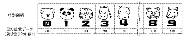
各停止図柄が上方に跳ねて至る位置B(戻り位置)は、一般に重量のあると認識されているキャラクタほど戻り位置が小さく(低く)なるように特別図柄毎に設定され、戻り位置データ(位置Aと位置Bとの距離を特定するデータ)として、図6に示すように、特別図柄に対応付けて、制御ROM134に予め格納されている。
The position B (return position) where each stop symbol jumps upward is set for each special symbol so that the return position becomes smaller (lower) as the character is generally recognized to be heavy. Return position data (position As data shown in FIG. 6, the distance between A and position B is stored in advance in the
図6に示す例では、コアラ、狸、狐(特別図柄「0」、「8」、「9」)等の軽量の小動物の戻り位置は「110」、パンダ(特別図柄「1」)の戻り位置は「100」、虎や馬(特別図柄「2」、「3」)の戻り位置は「90」、重い河馬(特別図柄「4」)の戻り位置は「70」というように、一般的に大きく重いと認識されているキャラクタほど戻り位置が小さく設定されている。
従って、図5(b)と(e)を比較すれば明らかなように、馬のキャラクタの特別図柄「3」の戻り位置の方が、河馬のキャラクタの特別図柄「4」よりも戻り位置が大きい(位置AとBの差が大きい;画面上の位置が高い)。
In the example shown in FIG. 6, the return position of light small animals such as koalas, pupae, pupae (special symbols “0”, “8”, “9”) is “110”, and the return position of the panda (special symbol “1”) The position is “100”, the return position of tigers and horses (special symbol “2”, “3”) is “90”, and the return position of heavy river horse (special symbol “4”) is “70”. The return position is set smaller for characters that are recognized as being larger and heavier.
Accordingly, as is apparent from a comparison between FIGS. 5B and 5E, the return position of the special symbol “3” of the horse character is more returnable than the special symbol “4” of the Kawama character. Large (the difference between positions A and B is large; the position on the screen is high).
各特別図柄は、変動中はアニメーション表示を行わないが、減速して停止直前の状態から跳ねて戻るという動作を行っている間は、例えば、図7に示すように、表示態様の異なる画像を順に切り替えて表示することにより、キャラクタや各数字について、時間の経過と共に徐々に図柄が変化するアニメーション表示を行う。 Each special symbol does not display an animation while it is fluctuating, but while performing the operation of decelerating and jumping back from the state immediately before the stop, for example, as shown in FIG. By switching and displaying in order, an animation display in which the symbols gradually change over time for characters and numbers.
なお、興趣を高めるため、例示した以外にも、様々な変動表示パターンが用意されている。 In addition, in order to enhance interest, various variable display patterns other than those illustrated are prepared.
図2のRAM102は、図3(b)に示すように、特図保留メモリ121、特図処理選択フラグ122、確変フラグ123、時短フラグ124、大当りフラグ125、特図変動時間タイマ126、等を格納する。
As shown in FIG. 3B, the
特図保留メモリ121は、現在実行中の特図ゲームに関する情報と、遊技球が普通可変入賞球装置6に入賞して特図ゲームを実行するための条件である実行条件(変動実行条件)が成立したが、従前の特図ゲームを実行中である等の理由のために変動を実際に開始するための開始条件(変動開始条件)が成立していない特図ゲームの保留情報を記憶するためのメモリである。
The special
具体的には、特図保留メモリ121は、第1〜第4の4個のエントリを備え、保留状態にある特図ゲームの情報を記憶する。第1〜第4の各エントリには、普通可変入賞球装置6への入賞による変動実行条件の成立順に、その入賞により抽出された乱数値が格納される。
Specifically, the special
特図ゲームが1回終了すると、第2〜第4エントリに登録されている保留情報が1エントリずつ繰り上がり、新たに第1エントリに登録された保留情報について変動開始条件が成立する。また、遊技球が普通可変入賞球装置6に新たに入賞した場合には、その入賞による乱数値が最上位の空エントリに登録される。
When the special game is finished once, the hold information registered in the second to fourth entries is incremented by one entry, and the variation start condition is established for the hold information newly registered in the first entry. Further, when a game ball newly wins the normal variable winning
特図処理選択フラグ122は、図15を参照して後述する特別図柄プロセス処理(特図ゲームを制御する処理)において、どの処理を選択・実行すべきかを示すフラグである。
The special figure
確変フラグ123は、パチンコ遊技機1の遊技状態が、確変状態(確率変動状態)に制御されているときに設定されるフラグである。確変状態は、特図ゲームにおいて大当りとなる確率が通常よりも高く設定されている状態である。
時短フラグ124は、パチンコ遊技機1の遊技状態が、時短状態に制御されているときに設定されるフラグである。時短状態は、特図ゲームにおける特別図柄の変動時間が通常よりも短く設定されている状態である。
確変状態及び時短状態は、通常の遊技状態よりも、遊技者に有利な遊技状態であり、変動時間の短い変動パターンが選択される。
The
The
The probability variation state and the short time state are gaming states that are more advantageous to the player than the normal gaming state, and a variation pattern with a short variation time is selected.
大当りフラグ125は、パチンコ遊技機1の遊技状態が、大当り状態、即ち、特定遊技状態に制御されているときに設定されるフラグである。特定遊技状態は、特図ゲームにおいて確定された特別図柄の組み合せが所定の大当り組合せ(例えば、同一図柄のゾロ目)となったときに設定される。特定遊技状態においては、特別可変入賞球装置7が所定期間(例えば、29秒)あるいは所定個数(例えば、10個)の入賞玉が発生するまで開放され、開放している間、遊技盤2の表面を落下する遊技球を受け止める。そして、受け止めた遊技球が、特別可変入賞球装置7内に設けられた特定領域(図示しない)を通過すること(V入賞)を条件として、閉鎖後、再び開放し、この開放サイクルを最高16回繰り返すことができる。
The
特図変動時間タイマ126は、特図ゲーム(変動表示装置上での特別図柄の変動)を開始してからの経過時間をカウントするためのカウンタである。
The special figure
図2に示す表示制御基板12は、主基板11とは独立して特図ゲームにおける表示制御をコンピュータプログラムに従って行うものであり、主基板11から送信される制御コマンドに基づいて、変動表示装置4の表示を制御する。
The
図8に示すように、表示制御基板12は、発振回路131と、リセット回路132と、CPU133と、制御ROM134と、RAM135と、ビデオディスプレイプロセッサ(以下、VDP:Video Display Processor)136と、画像ROM137と、VRAM(Video RAM)138と、LCD駆動回路139とを備えている。
As shown in FIG. 8, the
発振回路131は、CPU133及びVDP136に基準クロック信号を出力するものである。CPU133は、この基準クロック信号のパルス数をカウントすること等により、経過時間などを測定する。リセット回路132は、CPU133及びVDP136をリセットするためのリセット信号を出力するものである。
The
CPU133は、制御ROM134と協働し、変動速度方向指定手段、画像データ特定手段、変動表示制御手段等として機能する。具体的には、CPU133は、制御ROM134に格納されている動作プログラムを実行し、遊技制御用マイコン100から表示制御コマンドを受信するとRAM135を作業領域として用いながら制御ROM134から表示制御を行うための表示制御データを読み出す。CPU133は、読み出した表示制御データと主基板11からの表示制御コマンドとに基づいて、表示制御処理を行い、VDP136に描画命令を送る。
The
制御ROM134は、特定データ記憶手段として機能し、さらに、CPU133と協働して、変動速度方向指定手段及び表示領域特定手段、画像データ特定手段として機能する。具体的には、制御ROM134は、CPU133によって利用される各種制御プログラム及び制御データ等を格納する半導体メモリであり、例えば、CPU133が後述する表示制御動作を実行するための制御プログラムを格納する。制御ROM134は、各変動パターンについて、どの特別図柄をどのタイミングでどのサイズで表示するかといった情報をも格納している。
The
RAM135は、CPU133によって作業領域として利用される半導体メモリである。
The
VDP136は、表示装置制御機能及び高速描画機能を有し、CPU133からの描画命令に従って動作し、静止画および動画の変形(拡大縮小、トリミング)や合成などの処理を行う機能、展開した画像から表示部分をクリッピングして出力する機能等を有する。また、VDP136は、圧縮されている動画データについては、伸長する機能を有する。
The
画像ROM137は、画像データ記憶手段として機能するものであり、様々な映像を変動表示装置4に表示するための画像データを格納する。具体的には、画像ROM137は、図9(a)に示すように、各特別図柄を構成する「数字」の画像データを、特別図柄ごとに記憶し、さらに、その図柄に対応するキャラクタ図柄を特定する情報を格納している。
また、画像ROM137は、図9(b)に示すように、各特別図柄を構成する「キャラクタ」の画像データを、特別図柄ごとに記憶する。
The
Further, as shown in FIG. 9B, the
画像ROM137は、図7に例示したように、各特別図柄(数字とキャラクタのそれぞれ)について、複数の表示態様の画像データを格納しており、これらの画像をパラパラ漫画のように切り替えて表示すると、アニメーションが表示される。なお、各画像データが格納されている領域のアドレスを指定することにより、その画像データの特定と読み出しが可能である。
As illustrated in FIG. 7, the
制御ROM134には、図9(a)、(b)に示す各画像データを、特別図柄の種類と配列、アニメ画像表示(画像変化と変化順)により特定可能なデータ(インデックスデータ)が記憶されている(その詳細は後述する)。各特別図柄の画像は、数字とキャラクタ画像のそれぞれについて、特別図柄の番号とアニメ変動の番号とで、例えば、3−1(3:特別図柄の番号、1:アニメ変動の番号)といった形式で、特定可能である。
The
次に、制御ROM134に格納される表示制御データについて説明する。
表示制御データは、主基板11から、特定の表示パターンを指示する表示制御コマンドと最終停止図柄を指示する最終停止図柄指示コマンドが通知された際に、対応する変動表示を実行するためのものである。
Next, display control data stored in the
The display control data is for executing the corresponding variable display when the
表示制御データは、特図ゲームで表示制御される左図柄、右図柄、中図柄について、どのタイミングでどの画像(映像)データをどのように表示するかという情報を含む。 The display control data includes information on how to display which image (video) data at which timing for the left symbol, right symbol, and middle symbol that are display-controlled in the special figure game.
具体的には、制御ROM134に記憶されている表示制御データは、画像データ特定手段が使用する変動表示装置4上の特別図柄を表示するための表示領域の大きさを特定する情報、変動画像方向速度指定手段が使用する表示領域の移動速度と移動方向、画像データの拡大・縮小率、透明度、等の情報を含む。
Specifically, the display control data stored in the
また、制御ROM134は、制御データ記憶手段として機能し、図6を参照して説明した特別図柄別の戻り位置データを記憶する。即ち、特別図柄の変動表示の停止時に、戻り方向である第2の変動方向に変動する際の、戻り位置を示す量データ(戻り位置データ)と、変動が停止したときの基準位置(図5に示す位置A)を特定する位置データを格納する。
Further, the
表示領域の大きさを特定する情報とは、変動表示装置4の表示画面のうち、左図柄、右図柄、中図柄をそれぞれ表示する部分DL、DC,DRのサイズを示す情報である。
The information specifying the size of the display area is information indicating the sizes of the portions DL, DC, and DR that display the left symbol, the right symbol, and the middle symbol, respectively, on the display screen of the
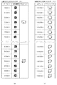
特定データ記憶手段としての制御ROM134には図10(a)に示すように、特別図柄の種類・配列(識別情報配列特定情報)と、特別図柄の画像変化・画像変化順(画像変化特定情報)を特定可能なインデックスデータテーブルT1が記憶されている。図9に示した画像ROM137に記憶されているそれぞれの画像データのアドレスは、インデックスデータテーブルT1から特定可能とされている。
As shown in FIG. 10A, the
インデックスデータテーブルT1における、特別図柄「0−1」等の表示は、画像ROM137に記憶されている特別図柄「0」のアニメ変動(画像変化)の「1」番目を意味する。そして、その「数字」の画像データは、アドレス0000H台に格納され、そのキャラクタの画像データは、アドレス10000H台に格納されている。
このインデックステータテーブルT1は、画像ROM137に記憶されている対応する画像データのアドレスを直接記憶してもよく、或いは、そのアドレスを特定するインデックス情報などを記憶するものでも良い。
The display of the special symbol “0-1” or the like in the index data table T1 means the “1” th of the animation variation (image change) of the special symbol “0” stored in the
The index data table T1 may directly store the address of the corresponding image data stored in the
さらに、制御ROM134には、特別図柄の表示領域(図5(a)のDL,DC,DR)の大きさを特定するデータとして図10(b)に示すように変動パターン(標準(縦スクロールで各表示領域に縦方向に特別図柄を3つ配置する)、1図柄(縦スクロールで各表示領域に1つの特別図柄を配置する)、横スクロール等)に対応した表示領域サイズ、表示領域それぞれの表示位置、抽出する特別図柄の数、表示領域の基準位置、特別図柄の拡大率、回転位置が記憶されている。
Further, the
また、制御ROM134には、変動速度方向指定手段が指定するデータとして、特別図柄の変動速度と方向を指定し、特別図柄の表示状態での変動速度を定義する変動速度データとして図10(c)のような1ドットあたりのスクロール時間を特定するデータ及び図10(d)に示すような変動方向を特定するデータが記憶されている。具体的には、変動パターン毎に、特別図柄の変動開始から停止までのテーブルとして、図10(e)に例示するように各特別図柄の変動開始から停止までの時間(基準クロックのカウント値)に応じた変動速度と、変動方向と、アニメ変動の有無がそれぞれ記憶されている。変動方向の「↓」は下方向(第1の変動方向)への縦スクロール、「↑」は上方向(第2の変動方向)への縦スクロール、「→」は右方向への横スクロール、「←」は左方向への横スクロ−ルを意味する。
Further, the
図10(e)に示す変動パターンの後半の4段階(アニメ変動開始以降)の変動速度、カウンタ、変動時間などは、前述の確定図柄(最終停止図柄)別の戻り位置までの戻り変動のために、停止図柄別に設定されている。これらは、停止図柄に対応してその都度演算等により求めてもよく、或いは、停止図柄別に予め求めておいて、制御ROM134の別のエリアに格納しておき、主基板11からの最終停止図柄指定コマンドにより指定された確定図柄に対応するものを読み出して設定するようにしてもよい。
The fluctuation speed, counter, fluctuation time, etc. in the latter half of the fluctuation pattern shown in FIG. 10 (e) (after the start of animation fluctuation) are due to return fluctuations up to the return position for each of the aforementioned fixed symbols (final stop symbols). Are set for each stop symbol. These may be obtained by calculation or the like each time corresponding to the stop symbol, or obtained in advance for each stop symbol, stored in another area of the
このような構成により、特別図柄の種類・配列(識別情報配列特定情報)と、特別図柄の画像変化・画像変化順(画像変化特定情報)とを特定可能なインデックスデータテーブルT1から特別図柄の画像データを特定し、変動速度方向指定手段(CPU133、制御ROM134)により特別図柄の変動速度と変動方向が特定され、指定された変動速度・方向と、表示領域特定手段(CPU133、制御ROM134)により特定された表示領域の大きさ(範囲)と、に基づいて、抽出する特別図柄の種類(0〜9)を特定する。さらに、画像デ一タ特定手段により表示領域内に表示する面像データを特定する。
With such a configuration, the image of the special symbol from the index data table T1 that can specify the type / arrangement of the special symbol (identification information arrangement specifying information) and the image change / image change order (image change specifying information) of the special symbol. The data is specified, the changing speed and direction of the special symbol are specified by the changing speed direction specifying means (
表示制御手段(VDP136)は該特定された画像データを画像ROM137から読み出し,表示領域指定手段により指定された表示領域の大きさに基づいて表示する画像を生成し、変動表示装置4に出力する処理を実行する。
The display control means (VDP 136) reads the specified image data from the
具体的に、図10(e)の速度・変動方向テーブルT2を用いて、変動表示状態での画像処理動作を説明する。ここでは、図5に示す変動表示において、左図柄と右図柄について、図10(e)に示す変動パターンが選択されているとする。
なお、確定図柄判定テーブル113を用いて判定された確定図柄(図5における「3」と「4」)に応じて、以下の表示制御が実現されるように、速度・変動方向テーブルT2の後半部分の変動速度とカウンタ値と変動時間が設定される。
Specifically, the image processing operation in the variable display state will be described using the speed / variation direction table T2 of FIG. Here, it is assumed that the variation pattern shown in FIG. 10E is selected for the left symbol and the right symbol in the variation display shown in FIG.
It should be noted that the second half of the speed / variation direction table T2 is implemented so that the following display control is realized according to the confirmed symbols ("3" and "4" in FIG. 5) determined using the determined symbol determination table 113. The fluctuation speed, counter value, and fluctuation time of the part are set.
なお、CPU133(又は、その内部カウンタ)は、特別図柄の変動開始から発振回路131から出力される基準クロックをカウントしており、このカウント値を同期制御に利用する。
The CPU 133 (or its internal counter) counts the reference clock output from the
まず、現在、変動表示装置4に表示している図柄が「6」であるとする。このような場合を、表示領域の位置が特別図柄の「6」を含む位置にあるとして考える。
この状態において、図10(e)の変動開始時のように、変動パターンとして、「1図柄(↓)」の変動パターン(表示領域(DL,DC,DR)に1つの特別図柄を表示して下方向にスクロールする)が指定され、アニメ変動が指定されていないとする。
First, it is assumed that the symbol currently displayed on the
In this state, as shown in FIG. 10 (e), when the variation pattern is changed, the variation pattern of “1 symbol (↓)” (one special symbol is displayed in the display area (DL, DC, DR)). Scroll down) is specified, and animation variation is not specified.
この状態では、特別図柄の変動表示は、大まかに、6,5,4・・・と順次変化する。 In this state, the change display of the special symbol roughly changes sequentially as 6, 5, 4.
ただし、段階的に変化するのではなく、表示はスムーズ(連続的)に変化する。以下、具体的な変動表示処理について説明する。
まず、図10(b)に示す表示領域サイズデータによれば、「1図柄(↓)」の変動パターンでの表示領域の大きさで抽出すべき特別図柄の数(抽出図柄数)は2である。現在の表示が「6」であるから、抽出する特別図柄の種類は「6」と「6」に続く「5」の2つとなる。
However, the display changes smoothly (continuously) instead of gradually. Hereinafter, specific variation display processing will be described.
First, according to the display area size data shown in FIG. 10B, the number of special symbols to be extracted (the number of extracted symbols) is 2 based on the size of the display area in the variation pattern “1 symbol (↓)”. is there. Since the current display is “6”, the types of special symbols to be extracted are two, “6” and “5” following “6”.
次に、表示対象の特別図柄の画像データの記憶位置のアドレスを図10(a)のインデックスデータテーブルT1を参照して判別し、特別図柄の「5」、「6」の画像データ(アニメ番号が1(即ち「5−1」の画像データと「6−1」の画像データ))を画像ROM137から読み出し、図11(a)に示すように縦方向に並べてVRAM138に展開する。この際、図10(a)に示すインデックスデータテーブルT1より、各特図を構成する数字の画像データと、キャラクタの画像データを特定し、それらを合成して展開する。
Next, the address of the storage position of the image data of the special symbol to be displayed is discriminated with reference to the index data table T1 in FIG. 10A, and the image data (anime number) “5” and “6” of the special symbol. Are read from the
次に、表示領域を図10(b)に示す表示領域サイズデータに定義される基準位置(0,150)(図11(b)にE1で示される位置)に位置させる。図10(b)に示す表示領域の大きさは(150、150)であり、この領域のサイズと位置で範囲でクリッビングし、フレームバッフを介して変動表示装置4に出力する。
Next, the display area is positioned at the reference position (0, 150) (position indicated by E1 in FIG. 11B) defined in the display area size data shown in FIG. The size of the display area shown in FIG. 10B is (150, 150), and the range is clicked with the size and position of the area and output to the
次に、図10(e)の速度・変動方向テーブルT2から特別図柄の変動速度(変動開始からの経過時間によるが、40、20,10、8...のいずれかの値)と、カウント値を順次読み出し、表示領域を、経過時間に応じて、上方向へ移動し(図11(b)のEX11〜EX13)、1フレーム時間毎に表示領域でクリッピングした画像をフレームバッファを介して順次、変動表示装置4に出力する。同様の処理を繰り返して、表示領域が150ドット上方向へ移動すると、図11(b)のE2の表示位置となり、表示領域の座標が(0,0)に到達する。
Next, from the speed / variation direction table T2 in FIG. 10 (e), the variation speed of the special symbol (depending on the elapsed time from the start of the variation, any value of 40, 20, 10, 8,. The values are sequentially read out, and the display area is moved upward according to the elapsed time (EX11 to EX13 in FIG. 11B), and images clipped in the display area every frame time are sequentially passed through the frame buffer. And output to the
すると、経過時間をリセットし、同様の処理により、特別図柄「4」と「5」の画像データを再度,展開するとともに、表示領域の位置を領域E2で示す基準位置である(0,150)に設定する。続いて、上記の処理を練り返す。
以後、同様の動作を繰り返す。
Then, the elapsed time is reset, and the image data of the special symbols “4” and “5” is developed again by the same process, and the position of the display area is the reference position indicated by the area E2 (0, 150). Set to. Subsequently, the above process is repeated.
Thereafter, the same operation is repeated.
左・中・右の各特別図柄について、これらの動作を繰り返し、さらに、左・中・右の画像を合成する制御を、特別図柄のスクロール表示の画像制御として実行する。 These operations are repeated for each of the left, middle, and right special symbols, and control for synthesizing the left, middle, and right images is executed as image control for scrolling the special symbols.
一方、特別図柄の変動が終了に近づいて、停止識別情報決定手段として機能する確定図柄判定テーブル113を用いてCPU101が決定した特別図柄の停止が近くなると、アニメ変動開始のタイミングになり、1図柄(↓)アニメ変動有りが指定される。また、この時点では、最終停止図柄の1つ前の図柄が表示されるように表示タイミングが設定されている。
On the other hand, when the change of the special symbol is nearing the end and the stop of the special symbol determined by the
CPU133は、表示領域のサイズから、抽出対象の特別図柄の数「2」を特定し、さらに、抽出対象の特別図柄を特定し、さらに、その特別図柄についての各表示態様の画像のアドレス(数字及びキャラクタ)をインデックスデータテーブルT1から判別して読み出し、図12或いは図13に示すように展開する。即ち、各特別図柄についての対応する表示態様用の数字の画像データとキャラクタの画像データとを合成して、2つの特別図柄の表示態様が異なる計18個の画像(図12では、数字とキャラクタについての「4−1」〜「4−9」、「3−1」〜「3−9」の合成画像;図13では、「5−1」〜「5−9」、「4−1」〜「4−9」の合成画像)をVRAM138上に展開する。図12は、図5(a)〜(c)に示す左図柄「3」の停止時の処理を、図13は、図5(d)〜(f)に示す右図柄「4」の停止時の処理を示す。
The
そして、経過時間(カウント値)に応じて、縦方向の切り出し位置と、横方向の切り出し位置を変更しながら、下スクロール(第1の変動方向:1図柄(↓))とアニメ変動とを実行し、最終停止図柄が基準位置(表示領域の中央)に達するように表示する(XX1〜XX3;YY1〜YY3)。 Then, depending on the elapsed time (count value), the vertical cutout position and the horizontal cutout position are changed, and the downward scroll (first fluctuation direction: one symbol (↓)) and animation fluctuation are executed. Then, the final stop symbol is displayed so as to reach the reference position (the center of the display area) (XX1 to XX3; YY1 to YY3).
XX3、YY3まで実行し、最終停止図柄が基準位置(図5の位置A)に位置すると、続いて、上スクロール(1図柄(↑))アニメ変動有りが指定され、XX4〜XX6、又はYY4〜YY6の位置に表示領域が順次設定される。このXX6,YY6の位置は、図5及び図6に示した戻り位置に相当する量(B1−A、B2−A)だけ上方向(第2の変動方向)に識別情報が移動するように設定される。 Execute up to XX3, YY3, and when the final stop symbol is located at the reference position (position A in FIG. 5), next, the up scroll (1 symbol (↑)) animation change is designated, XX4 to XX6, or YY4 to A display area is sequentially set at the position of YY6. The positions of XX6 and YY6 are such that the identification information moves upward (second variation direction) by an amount (B 1 -A, B 2 -A) corresponding to the return position shown in FIGS. Set to
XX6、YY6まで実行し、最終停止図柄が戻り位置(図5の戻り位置B1又はB2)に達すると、続いて、下スクロール(1図柄(↓))アニメ変動有りが指定され、XX7〜XX8又はYY7〜YY8の位置に表示領域が順次設定される。最後に、表示領域がXX9又はYY9の位置に達すると、即ち、各最終停止図柄が図5及び図6に示した基準位置Aに位置すると、変動が停止し、表示が確定する。 XX6, run up YY6, the final stop symbols returns reaches the position (return position B 1 or B 2 in FIG. 5), followed by down scroll (1 symbol (↓)) Animation There variation is specified, XX7~ Display areas are sequentially set at positions XX8 or YY7 to YY8. Finally, when the display area reaches the position XX9 or YY9, that is, when each final stop symbol is located at the reference position A shown in FIGS. 5 and 6, the fluctuation is stopped and the display is fixed.
以上説明したように、表示対象の特別図柄をアニメ変動の内容にあわせてマトリクス状に展開し、計時手段が所定時間(カウント)を計時すると、計時時間に応じて、縦方向の切り出し位置と、横方向の切り出し位置を変更しながら、上下スクロールとアニメ変動とを実行し、特別図柄の変動の終了時に、下方向(第1変動方向)への変動を行って、続いて、停止図柄毎に予め定められている戻り位置まで上方向(第2の変動方向)に戻って、更に、下方向(第1変動方向)にスクロールするという変動表示が行われ、実世界でのキャラクタの特徴に応じたアニメーション表示が可能となる。 As described above, the special symbol to be displayed is expanded in a matrix according to the contents of the animation variation, and when the time measuring means measures a predetermined time (count), the vertical cutout position is determined according to the time measured, While changing the cutout position in the horizontal direction, execute vertical scrolling and animation variation, and at the end of the variation of the special symbol, perform the variation downward (first variation direction), and then for each stop symbol Depending on the characteristics of the character in the real world, the display returns to a predetermined return position in the upward direction (second variation direction) and then scrolls downward (first variation direction). Animation display is possible.
このように、特別図柄の変動パターンを指定するそれぞれのデータを制御ROM134に上記のように格納して制御することにより、特別図柄の配列やアニメ変動(両像変化・画像変化順)を変動パターンごとにすべて記憶する必要がなくなり、記憶容量(画像ROM137またはVRAM138)を低減することが可能となる。また、表示制御基板12のCPU133は、常時指定された画像データを生成し表示領域の範囲でクリッビングするといった定型処理を実行することにより制御負担を軽減することができる。また、表示領域の大きさや、特別図柄の変動方向のデータのみを変えることにより、特別図柄の変動態様を制御負担を増加せずに増加し、縦スクロールから横スクロールといった多彩な特別図柄の変動態様を制御することが可能とし、さらに遊技者への遊技演出を向上させることができる。
Thus, by controlling to store the respective data to specify the variation pattern of the special symbols as the control ROM134 above, varying the sequence and anime variation of the special symbols (both images change, image change order) pattern Therefore, it is not necessary to store all the data every time, and the storage capacity (
さらに、最終停止図柄に応じて、変動停止時に、下スクロールから上スクロールへの戻り量を制御することにより、表示されるキャラクタの実社会での重量やサイズに応じた表示が可能となり、臨場感を与えることができる。 Furthermore, by controlling the amount of return from the bottom scroll to the top scroll when the variable stop is performed according to the final stop symbol, it becomes possible to display according to the weight and size of the displayed character in the real world, giving a sense of reality. Can be given.
制御ROM134に格納される画像データの拡大・縮小率は選択された画像の拡大・縮小率であり、サイズ指定手段により指定するサイズである。画像データの透明率は下地の画像が透けて見える程度を示し、透過率指定手段により、指定する透過率である。画像データの拡大・縮小率及び透過率は、表示領域D内の位置毎に異なった値に設定することも可能である。表示制御手段は、サイズ指定手段より指定されたサイズ並びに透過率指定手段により指定された透過率に基づいた画像を生成する。
The enlargement / reduction ratio of the image data stored in the
図8に示すVRAM138は、VDP136によって生成(合成)された画像データを展開するためのフレームバッファメモリである。
A
LCD駆動回路139は、VDP136から入力された画像データを、色信号と同期信号とからなるビデオ信号に変換し、変動表示装置4に出力する。
The
表示制御基板12は、以上の構成により、遊技制御用マイコン100から、最終停止図柄と選択された変動パターンを指定する情報等を含む変動開始コマンドを受信すると、指定された変動パターンに従って特別図柄を変動させ、左図柄、右図柄、中図柄の順で、指定された最終停止図柄で図柄の変動を停止して最終停止図柄を確定する。
When the
図5を参照して説明した変動パターンの表示制御データの例を図14に示す。
この例では、i)特別図柄の変動の開始後、左・中・右の各特別図柄が下方向(第1の変動方向)に流れる(スクロールする)ように表示される。このときアニメ変動はない。また、特別図柄は、数字とキャラクタの組である。
続いて、ii)左図柄がアニメ変動を伴って、減速して基準位置で一旦停止し、続いて、最終停止図柄別に定まる戻り位置まで戻る変動表示を行い、続いて、基準位置に復帰する。この間、中図柄と右図柄とは、アニメ変動の無い変動を継続する。
続いて、iii)右図柄がアニメ変動を伴って、減速して基準位置で一旦停止し、続いて、最終停止図柄別に定まる戻り位置まで戻る変動表示を行い、続いて、基準位置に復帰する。この間、左図柄は停止しており、中図柄は、アニメ変動の無い変動を継続する。
さらに、iv)中図柄がアニメ変動を伴って、減速して基準位置で一旦停止し、続いて、最終停止図柄別に定まる戻り位置まで戻る変動表示を行い、続いて、基準位置に復帰する変動を行う。この間、左図柄と右図柄は停止しており、中図柄は、アニメ変動の無い変動を継続する。
最後に、v)中図柄が基準位置に復帰すると、左・中・右の最終停止図柄が確定し、大当り、ハズレが決定する。
An example of the display control data of the variation pattern described with reference to FIG. 5 is shown in FIG.
In this example, i) After the start of the variation of the special symbol, the left, middle and right special symbols are displayed so as to flow (scroll) downward (first variation direction). There is no animation change at this time. The special symbol is a set of numbers and characters.
Subsequently, ii) the left symbol is decelerated with animation variation, temporarily stops at the reference position, and then the variation display is returned to the return position determined for each final stop symbol, and then returns to the reference position. During this time, the middle symbol and the right symbol continue to fluctuate without animation fluctuation.
Subsequently, iii) the right symbol is decelerated with animation variation, temporarily stops at the reference position, and then the variation display for returning to the return position determined for each final stop symbol is performed, and then the reference symbol is restored. During this time, the left symbol is stopped, and the middle symbol continues to fluctuate without animation variation.
Furthermore, iv) The middle symbol is decelerated with animation variation, temporarily stops at the reference position, and then displays a variation display that returns to the return position determined by the final stop symbol, followed by the variation that returns to the reference position. Do. During this time, the left symbol and the right symbol are stopped, and the middle symbol continues to fluctuate without animation variation.
Finally, v) When the middle symbol returns to the reference position, the left, middle and right final stop symbols are determined, and the big hit and the loss are determined.
次に、本実施例のパチンコ遊技機1の動作(作用)を説明する。まず、本実施例のパチンコ遊技機1における遊技の流れの概略について説明する。
Next, the operation (action) of the
パチンコ遊技機1の右下位置に設けられたハンドルを操作することにより、遊技領域中に遊技球が発射される。主基板11の遊技制御用マイコン100は、スイッチ回路107の出力から、遊技球が普通可変入賞球装置6に入賞したことを検出すると、乱数回路104により乱数値を発生し、得られた乱数値を図3(b)に示す特図保留メモリ121の空きエントリの先頭に保留情報として記憶する。
By operating a handle provided at the lower right position of the
遊技制御用マイコン100は、特図保留メモリ121の第1エントリに記憶されている保留情報を読み出して、読み出した保留情報に対応する特図ゲームを実行する。即ち、特図保留メモリ121の第1エントリに設定されている乱数値から、大当りとするかハズレとするかを決定する。さらに、大当りとするかハズレとするかの別に応じて、特別図柄の表示結果(最終停止図柄)の組み合わせを決定する。
The
遊技制御用マイコン100は、変動パターン判定テーブル114に格納されている複数の変動パターンのうちから状況に応じたものを選択し、その制御コードを取得する。遊技制御用マイコン100は表示制御基板12へ、特図ゲームを開始することと最終停止図柄と変動パターンとを指定する制御コードとを指示する変動開始コマンドを送信する。遊技制御用マイコン100は変動開始コマンド送信後の経過時間を計測し、総変動時間が経過すると、表示確定コマンドを送信する。
The
表示制御基板12は、遊技制御用マイコン100から供給される変動開始コマンドに応じて、表示制御データを読み出し、この表示制御データに従って、画像データを読み出して、変動表示装置4に表示することにより、特別図柄の変動(可変)表示を制御して表示結果を導出する(変動表示制御手段)。
The
表示制御基板12は、遊技制御用マイコン100より確定コマンドを受信すると、最終的な図柄を確定する。最終停止図柄が、大当り図柄(3つの特別図柄の図柄が揃った状態)であれば、パチンコ遊技機1は大当り状態(特定遊技状態)となり、特別可変入賞球装置7の開閉板が一定時間又は一定数の遊技球が入賞するまで開成し、V入賞を条件に開閉を一定サイクル繰り返す。一方、最終停止図柄が、ハズレ図柄であれば、特別可変入賞球装置7の開閉板の開成等は行わない。
When receiving the confirmation command from the
遊技者は、このようにして特図ゲームを行って特別可変入賞球装置7に遊技球を入賞させ、払出制御部により払い出される賞球を獲得する。
In this way, the player plays the special game and causes the special variable winning
以下、遊技制御用マイコン100が実行する特図ゲームの処理(変動表示制御手段)を図15〜図21を参照して説明する。
Hereinafter, the special game processing (fluctuation display control means) executed by the
遊技制御用マイコン100は、例えば、2m秒毎のタイマ割り込み等で、図15のフローチャートに示す特別図柄プロセス処理を開始する。
The
遊技制御用マイコン100は、まず、遊技球が普通可変入賞球装置6に入賞したか否かを、入賞玉検出器の出力をチェックすることにより検出する(ステップS111)。遊技球が入賞した場合(ステップS111;Yes)、入賞処理を実行し(ステップS112)、遊技球が入賞していない場合(ステップS111;No)、入賞処理(ステップS112)をスキップする。
The
ステップS112の入賞処理においては、図16に示すように、特図保留メモリ121の保留数が上限値の4以上であるか否かを判別する(ステップS201)。保留数が4以上であれば(ステップS201;Yes)、今回の入賞による特図ゲームの始動は無効として特に何も行わず、一方、保留数が上限値の4未満である場合には(ステップS201;No)、乱数回路104を起動して乱数値を抽出する(ステップS202)。次に、抽出した乱数値を特図保留メモリ121の空エントリの先頭にセットする(ステップS203)。
In the winning process of step S112, as shown in FIG. 16, it is determined whether or not the number of holds in the special
次に、遊技制御用マイコン100は、特図処理選択フラグ122の値に基づいて、図15に示すステップS100〜107の8つの処理のうちのいずれかを選択する。
Next, the
ステップS100の特別図柄通常処理は、特図処理選択フラグ122が初期値「0」のときに実行される処理である。この処理において、遊技制御用マイコン100は、特図保留メモリ121に保留情報が格納されているか否かを判別し、格納されているときに、第2〜第4エントリの各保留情報を1エントリずつ上位にシフトし、新たに第1エントリに格納された乱数値を読み出し、特図処理選択フラグ122の値を「1」に更新する。
The special symbol normal process of step S100 is a process executed when the special symbol
ステップS101の特別図柄停止図柄設定処理は、特図処理選択フラグ122の値が「1」の場合に実行され、特図ゲームの表示結果を事前決定する処理である。この処理において、遊技制御用マイコン100は、特図保留メモリ121の第1エントリに保持されている乱数値を用いて、表示結果を決定(事前決定)する。具体的には、図17に示すように、その時点での遊技状態(確変フラグ123,時短フラグ124の内容で特定される確変状態、時短状態等)に応じた大当り判定テーブル112を選択し(図17;ステップS301)、ステップS100で特図保留メモリ121の第1エントリから読み出した乱数値を選択した抽選テーブルに適用して、大当りか否かを事前(特図ゲームが開始する前に)判定する(ステップS302)。
The special symbol stop symbol setting process of step S101 is executed when the value of the special symbol
大当りの場合には(ステップS303;Yes)、さらに、乱数回路104を起動して乱数値を抽出して、確定図柄判定テーブル113に適用して大当りの表示結果(最終停止図柄の組み合わせ)を決定する(ステップS304;停止識別情報決定手段)。一方、ハズレの場合には(ステップS303;No)、各図柄について乱数値を抽出して、確定図柄判定テーブル113に適用して、左・中・右の図柄の表示結果(確定図柄)を決定する(ステップS305;停止識別情報決定手段)。その後、特図処理選択フラグ122の値を「2」に更新する(ステップS306)。
In the case of a big hit (step S303; Yes), the
ステップS102の変動パターン設定処理は、特図処理選択フラグ122が「2」の場合に実行される処理である。この処理において、遊技制御用マイコン100は、特図ゲームを行う際に使用する変動パターンを、変動パターン判定テーブル114に格納されている変動パターンのうちから選択する。
The variation pattern setting process of step S102 is a process executed when the special figure
この変動パターン設定処理において、図18に示すように、遊技制御用マイコン100は、確変フラグ123又は時短フラグ124が設定されているか否か、即ち、特図ゲームにおける変動時間を通常よりも短くする時短制御処理が有効状態にされているか否かを判別する(ステップS401)。確変フラグ123又は時短フラグ124がオン(ステップS401;Yes)の場合には、時短用の変動パターンで、且つ、ステップS101で設定した当りかハズレを導出可能なもののうちから1つを、例えば乱数を発生させる等して選択する(ステップS402)。
In this variation pattern setting process, as shown in FIG. 18, the
一方、確変フラグ123と時短フラグ124とが共にオフの状態にあるときには(ステップS401;No)、通常の変動パターンのうちで、且つ、ステップS101で設定した最終停止図柄を導出可能なもののうちから1つを、例えば乱数を発生させる等して選択する(ステップS403)。
On the other hand, when both the
続いて、特図変動時間タイマ126に、選択した変動パターンに割り当てられている総変動時間に相当するカウント値を設定する(ステップS404)。 Subsequently, a count value corresponding to the total variation time assigned to the selected variation pattern is set in the special figure variation time timer 126 (step S404).
続いて、特図ゲームの開始と最終停止図柄と変動パターンとを指定する制御コードとを指示する変動開始コマンドと、3つの確定図柄(最終停止図柄)を指定する最終停止図柄指定コマンドとを、表示制御基板12に送信する(ステップS405)。続いて、特図処理選択フラグ122の値を「3」に更新する(ステップS406)。
Subsequently, a variation start command for designating the start of the special figure game, a final stop symbol, and a control code for designating the variation pattern, and a final stop symbol designation command for designating three final symbols (final stop symbol), It transmits to the display control board 12 (step S405). Subsequently, the value of the special figure
ステップS405で送信したコマンドは、表示制御基板12に受信される。表示制御基板12は、変動開始コマンドに含まれている情報から、変動表示に使用する表示制御データを特定し、この表示制御データが規定するタイムスケジュールに沿って、変動表示装置4に特別図柄が変動してから停止するまでの画像を表示する処理を行う。また、受信した最終停止図柄指定コマンドから、左・中・右の各確定図柄を判別する。
The command transmitted in step S405 is received by the
CPU133は、変動開始コマンドに応答して、制御ROM134に格納されている表示制御データのうちから、受信した変動開始コマンドが指定する変動パターンに対応するものを読み出す。そして、カウンタ(タイマ)をリスタートして、変動開始からの経過時間を開始する。また、アニメ画像切り替え用のタイマをリスタートする。
In response to the change start command, the
さらに、この実施の形態では、図19に示すように、表示制御CPU133は、今回の変動パターンが図5を参照して説明した「戻り変動」を伴うものであるか否か(換言すれば、図10(e)な変動パターンであるか否か)を判別する(ステップS1001)。戻り変動を伴うものである場合には(ステップS1001;Yes)、最終停止図柄指定コマンドにより指定された最終停止図柄に応じて、図10(e)で示した変動パターンテーブルの空欄分に、表示制御データを設定する必要がある。そこで、戻り変動を伴うものである場合には、最終停止図柄(ステップS304又はS305で決定したもの)を特定し、さらに、図6に示す戻り位置データから戻り位置(戻り量)を判別する(ステップS1002)。
Furthermore, in this embodiment, as shown in FIG. 19, the
続いて、判別した戻り量が達成されるように、変動速度、変動時間などの情報を今回選択された速度・方向テーブルT2に設定し、作業を終了する(ステップS1003)。なお、この処理は、最終停止図柄別に予め用意しておいた値を設定するものでもよく、その都度、演算等により求めるものでもよい。 Subsequently, information such as the fluctuation speed and the fluctuation time is set in the speed / direction table T2 selected this time so that the determined return amount is achieved, and the operation is finished (step S1003). In this process, a value prepared in advance for each final stop symbol may be set, or may be obtained by calculation or the like each time.
また、CPU133は、発振回路131の基準クロックをカウントして、一定期間を計測する度に、図20に示す描画指示処理を実行する。
Further, the
まず、CPU133は、その時点でVRAM138上に展開すべきデータを特定する。
First, the
即ち、主基板11から通知された変動パターンの情報に基づいて、その変動パターン用の速度変動方向テーブルT2を参照し、変動開始コマンド受信後の経過時間を読み出して、その時点での変動方向とアニメ変動の有無を判別する。続いて、図10(b)に示す表示領域サイズデータを参照して、変動方向に対する抽出図柄数を求める(ステップS502)。
That is, based on the variation pattern information notified from the
次に、抽出図柄数と現在の変動表示の状態から、抽出する特別図柄(0〜9)を特定する(ステップS503)。アニメ変動無しならば、各特別図柄について基準となる表示態様の画像を特定し、アニメ変動有りならば、各特別図柄について各表示態様の画像を特定する。 Next, a special symbol (0 to 9) to be extracted is specified from the number of extracted symbols and the current fluctuation display state (step S503). If there is no animation variation, the image of the display mode used as a reference is specified for each special symbol, and if there is animation variation, the image of each display mode is specified for each special symbol.
次に、特定された特別図柄(0〜9)を、対応する拡大率、回転角度で、予め指定されている配列(縦並びや予横並び)で仮想的に配置する(ステップS504)。なお、画像データを実際に配列する必要はない。 Next, the specified special symbols (0 to 9) are virtually arranged in a predesignated arrangement (vertical arrangement or pre-horizontal arrangement) with a corresponding enlargement ratio and rotation angle (step S504). It is not necessary to actually arrange the image data.
次に、仮想的に配置した画像上の表示領域の位置を、直前の位置、移動速度、移動方向、アニメ変動の有無から特定する(ステップS505)。 Next, the position of the display area on the virtually arranged image is specified from the immediately preceding position, the moving speed, the moving direction, and the presence / absence of animation fluctuation (step S505).
次に、仮想的に配置した画像上の表示領域内部の位置(表示する範囲)を、表示領域の位置とサイズとに基づいて特定する(ステップS506)。 Next, the position (display range) inside the display area on the virtually arranged image is specified based on the position and size of the display area (step S506).
また、ステップS503で特定した特別図柄と経過時間のデータから、表示対象の図柄(数字とキャラクタそれぞれ)が格納されているアドレスを、図10(a)のインデックスデータテーブルT1を参照して求める(ステップS507)。 Further, from the special symbol specified in step S503 and the elapsed time data, the address at which the symbol (character and character) to be displayed is stored is obtained with reference to the index data table T1 in FIG. Step S507).
次に、求めた展開すべき画像データのアドレス、配置、拡大率・縮小率、透過率(予め設定されている)、クリッピング範囲などを特定する、即ち、表示対象画像を特定する描画コマンド又は/及びアトリビュートデータを生成し、VDP136に送信する。
Next, the address, arrangement, enlargement / reduction ratio, transmittance (preset), clipping range, etc. of the obtained image data to be developed are specified, that is, a drawing command for specifying a display target image or / And the attribute data are generated and transmitted to the
VDP136は、図20(b)に示すように、指示された描画コマンド又はアトリビュートで特定される画像の画像データ(指定されたアドレスに格納されている画像データ)を画像ROM137に格納されている画像データの中から抽出する(ステップS511)。
As shown in FIG. 20B, the
さらに、読み出した画像データを拡大・縮小・回転・透過処理を行って配置し直して、VRAM138上に展開する(ステップS512)。 Further, the read image data is rearranged by performing enlargement / reduction / rotation / transparency processing and developed on the VRAM 138 (step S512).
次に、展開した画像データを通知されたクリッピング範囲でクリッピングする(ステップS513)。 Next, clipping clipping range which is notified the image data expanded (step S513).
CPU133とVDP136とは、上述の処理を、左図柄、中図柄、右図柄のそれぞれについて実行し、最終的に1画面分の画像を合成する。
The
一方で、VDP136は、図20(c)に示すように、VRAM138上の画像データ(例えば、RGB輝度データ)を所定の周期的タイミング(例えば、30ms)で読み出し、LCD駆動回路139に供給する。LCD駆動回路139は、供給された画像データに従って、LCD駆動信号等の制御信号を生成し、これを変動表示装置4に供給することにより、変動表示装置4の画面に特別図柄や背景を表示させる。
On the other hand, as shown in FIG. 20C, the
このような動作を繰り返すことにより、例えば、特図ゲームが開始してから、図5を参照して説明したような、パチンコ遊技機1による遊技の状況(特図ゲームの状況等)に応じた表示が行われる。
By repeating such an operation, for example, after the start of the special figure game, according to the game situation (the situation of the special figure game) by the
そして、例えば、図11〜図13に示すような図柄配列とアニメーション表示配列とで指定可能な各表示画像を備えるだけで、表示領域のサイズに応じた特別図柄の変動及び静止表示と、各特別図柄のアニメーション表示とを同時に行うことができる。 And, for example, only by providing each display image that can be specified by the symbol arrangement and the animation display arrangement as shown in FIGS. 11 to 13, special symbol variation and static display according to the size of the display area, and each special display The animation display of the design can be performed simultaneously.
表示制御基板12が、変動表示を行っている間、遊技制御用マイコン100は、図15のステップS103の特別図柄変動処理を繰り返して実行する。なお、この処理は、特図処理選択フラグ122の値が「3」の場合に実行される処理である。この処理では、図21に示すように、遊技制御用マイコン100は、特図変動時間タイマ126のカウント値を1だけ減算する(ステップS601)。続いて、特図変動時間タイマ126の値が0であるか否か、すなわち、特別図柄を設定された変動時間だけ変動させたか否かが判別される(ステップS602)。
While the
特図変動時間タイマ126=0と判別された場合(ステップS602;Yes)には、1回の特図ゲームが丁度終了したタイミングであり、遊技制御用マイコン100は、特図処理選択フラグ122を「4」とする(ステップS603)。
When it is determined that the special figure
一方、ステップS602で特図変動時間タイマ126=0ではないと判断されたとき(ステップS602;No)には、今回の割り込み処理を終了する。
On the other hand, when it is determined in step S602 that the special figure
図15のステップS104の特別図柄停止設定処理は、特図処理選択フラグ122の値が「4」の場合に実行される処理である。この処理において、遊技制御用マイコン100は、表示制御基板12に、確定コマンドを送信する。また、特図ゲームの終了に同期して、動作する必要のある各部に特図ゲームの終了を通知する。さらに、遊技制御用マイコン100は、最終停止図柄が当りに相当する場合には、大当りフラグ125を設定し、特図処理選択フラグ122を「5」に更新し、ハズレに相当する場合には、特図処理選択フラグ122を「0」に更新する。
The special symbol stop setting process in step S104 of FIG. 15 is a process executed when the value of the special symbol
表示制御基板12のCPU133は、ステップS104の特別図柄停止設定処理において送出された確定コマンドを受信すると、特別図柄の確定表示(特別図柄の変動を停止する表示)を実行する。このとき、特別図柄の模様が変化するように、アニメーション処理を継続してもよい。
When the
図15のステップS105の大入賞口開放前処理は、特図処理選択フラグ122の値が「5」の場合に実行される処理である。この処理において、遊技制御用マイコン100は、特別可変入賞球装置7を開放する前の演出を行うための処理、例えば、第1回目の開放前や開放処理間のインターバル演出等の処理を行う。特別可変入賞球装置7を開放するタイミングになると、特図処理選択フラグ122の値を「6」に更新する。
The process for pre-opening the special winning opening in step S105 in FIG. 15 is a process executed when the value of the special figure
ステップS106の大入賞口開放中処理は、特図処理選択フラグ122の値が「6」の場合に実行される処理である。この処理では、遊技制御用マイコン100は、開放された特別可変入賞球装置7への遊技球の入賞処理、開放時間の計測処理、表示制御基板12を介した表示制御等を行う。遊技制御用マイコン100は、入賞球数が所定数に達するか開放時間が所定時間に達すると、特図処理選択フラグ122の値を更新する。遊技制御用マイコン100は、1回の大当りについて、特別可変入賞球装置7の開放回数をカウントしており、特図処理選択フラグ122を更新する際に、開放回数が16回に達していれば、大当り状態を終了する条件が成立したとして特図処理選択フラグ122の値を「7」とし、開放回数が16回に達していなければ、特別可変入賞球装置7を一旦閉成した後、特定領域への遊技球の通過があったか否か(V入賞の有無)を判別し、通過があったなら、特図処理選択フラグ122を「5」に、無しなら「7」とする。これにより、大当り状態にあっては、特別可変入賞球装置7の開閉が最大16回繰り返されることになる。
The special winning opening opening process in step S106 is a process executed when the value of the special figure
図15のステップS107の大当り終了処理は、特図処理選択フラグ122の値が「7」の場合に実行される処理であり、遊技制御用マイコン100は、大当り状態を終了させる処理を行い、特図処理選択フラグ122の値を「0」とする。
The jackpot ending process in step S107 of FIG. 15 is a process executed when the value of the special figure
なお、遊技制御用マイコン100はスイッチ回路107から入力されるスイッチ信号及びハンドル操作信号などの有無を判別しており、このパチンコ遊技機1が遊技状態に無い時には、表示制御基板12にデモ画面表示コマンドを送信して変動表示装置4にデモンストレーション画像を表示させる。
The
以上説明したように、この実施の形態によれば、様々な場面で、スプライト画像と動画とが連続する表示して映像(画像)を表示する場合に、画像の切り替わりのときの表示がスムーズで観察者に違和感を与えることが少ない。 As described above, according to this embodiment, when a video (image) is displayed by continuously displaying a sprite image and a moving image in various scenes, the display at the time of switching of images is smooth. There is little discomfort to the observer.
なお、この発明は上記実施の形態に限定されず、種々の変形及び応用が可能である。 In addition, this invention is not limited to the said embodiment, A various deformation | transformation and application are possible.
上記実施の形態では、変動開始時に図10(e)に示す変動パターンテーブルT2の空欄を埋めるようにしたが、最終停止図柄別に予めテーブルを用意しておき、いずれかのテーブルを選択するようにしてもよい。 In the above embodiment, the blank of the variation pattern table T2 shown in FIG. 10E is filled at the start of variation. However, a table is prepared in advance for each final stop symbol, and one of the tables is selected. May be.
また、例えば、通常の変動表示と演出変動表示時で、各特別図柄の柄(模様)を変更して、異なったアニメーション表示を可能としてもよい。
例えば、通常の変動表示用には、図7、図9等に示した画像データ(第1の識別情報画像データ)を画像ROM137に記憶し、演出変動表示用には、異なるアニメーション表示用の画像データ(第2の識別情報画像データ)を画像ROM137に記憶しておき、リーチ状態が成立した後のリーチ演出時、最終停止図柄を大当り図柄で停止させた時の大当り演出表示、大当りになることやリーチになることを予告するための予告演出(大当り予告、リーチ予告)などの一定の演出の条件が成立したことを契機として、画像データ特定手段により特定する対象を切り替えて、演出用の画像データを用いた表示を行ってもよい。
Further, for example, different animation displays may be possible by changing the pattern (pattern) of each special symbol during normal variation display and effect variation display.
For example, the image data (first identification information image data) shown in FIGS. 7 and 9 is stored in the
また、上記説明において、表示領域内の特別図柄のサイズを1倍の場合を中心に説明したが、倍率は任意である。なお、特別図柄を拡大した結果、表示領域の外にはみ出す部分については、クリッピングにより除去される。また、演出に応じて、適宜、2倍、3倍、1/2倍...に特別図柄のサイズを指定するようにしてもよい。 In the above description, the case where the size of the special symbol in the display area is 1 times has been mainly described, but the magnification is arbitrary. Note that, as a result of enlarging the special symbol, a portion that protrudes outside the display area is removed by clipping. Further, the size of the special symbol may be designated as appropriate, such as 2 times, 3 times, 1/2 times ... depending on the production.
また、制御ROM134に、変動パターン別に表示領域のサイズ、移動速度・移動方向等を特定するデータを格納しておき、描画処理を行うたびに、CPU133が表示対象の画像データを特定して、クリッピングして表示対象画像を用意したが、変動パターン毎に経過時間毎に表示対象特別図柄(これは変動開始時の初期状態により異なる)とアニメ変動インデックス、クリッピング範囲を特定するデータを予め用意しておき、これらに基づいて、表示対象画像を生成するようにしてもよい。
Further, the
特別図柄の画像データとして、予め第1表示画像(例えば、キャラクタ)と第2表示画像(例えば、数字)が合成された画像データとしてもよい。この場合、アニメ変動ありの場合の画像データと、アニメ変動無しの場合の画像データとをそれぞれ用意して画像ROM137に格納しておいてもよい。
The image data of the special design may be image data obtained by combining a first display image (for example, a character) and a second display image (for example, a number) in advance. In this case, image data when there is animation variation and image data when there is no animation variation may be prepared and stored in the
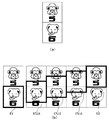
また、特別図柄が、第1表示画像(例えば、キャラクタ)と第2表示画像(例えば、数字)の合成画像から構成されることを利用して、例えば、図22(a)〜(g)に示すような変動表示を行うようにしてもよい。即ち、図22(a)に示すように、変動表示装置4の左・中・右の各変動表示領域で、数字とキャラクタとから構成される左・中・右の各特別図柄が変動を開始する。
Further, using the fact that the special symbol is composed of a composite image of a first display image (for example, a character) and a second display image (for example, a number), for example, in FIGS. You may make it perform the fluctuation | variation display as shown. That is, as shown in FIG. 22A, the left, middle and right special symbols composed of numbers and characters start to fluctuate in the left, middle and right fluctuating display areas of the fluctuating
続いて、左図柄と右図柄とが順次停止する。ここで、図22(b)に示すようにリーチ状態が成立すると、続いて、左図柄表示領域と右図柄表示領域に次の図柄が表れ、従前に停止していた図柄に衝突して停止する。これにより、ダブルリーチ状態が成立する。このとき、前述したような停止した図柄の種類に応じてて戻るような変動表示をおこなってもよい。 Subsequently, the left symbol and the right symbol are sequentially stopped. Here, when the reach state is established as shown in FIG. 22 (b), the next symbol appears in the left symbol display area and the right symbol display area, and then collides with the previously stopped symbol and stops. . Thereby, a double reach state is established. At this time, the display may be changed so as to return according to the type of the stopped symbol as described above.
すると、図22(c)、(d)に示すように、特別図柄のキャラクタの画像が消えて、数字のみとなる。キャラクタの画像を画面から消去する手法は任意である。
続いて、図22(e)〜(g)に示すように、中図柄が変動を継続しつつ、左図柄と右図柄は、数字のみのアニメーション表示を行う。このとき、上述のキャラクタの種類に応じた戻り変動を行う。
続いて、図示はしていないが、中図柄の変動が停止する。このとき、上述のキャラクタの種類に応じた戻り変動を行う。最終的に、左・中・右の各図柄が確定すると、大当り又はハズレが確定する。
このような表示制御によれば、変動中とリーチ成立後の表示形態が異なり、多様な表示を行うことができ、興趣を高めることができる。また、限られた表示エリアに多数の特別図柄を表示するときに、表示エリアを有効に利用することができる。
Then, as shown in FIGS. 22 (c) and 22 (d), the image of the special symbol character disappears, and only the numbers are displayed. Any method can be used for erasing the character image from the screen.
Subsequently, as shown in FIGS. 22E to 22G, while the middle symbol continues to change, the left symbol and the right symbol perform animation display of only numbers. At this time, the return fluctuation according to the type of the character is performed.
Subsequently, although not shown in the figure, the change of the middle symbol stops. At this time, the return fluctuation according to the type of the character is performed. Eventually, when each of the left, middle, and right symbols is confirmed, the big hit or the loss is confirmed.
According to such display control, the display form after the reach is established is different from that during the change, and various displays can be performed, and the interest can be enhanced. In addition, when a large number of special symbols are displayed in a limited display area, the display area can be used effectively.
上記実施の形態においては、CPU133が、表示制御データを処理し、VDP136にコマンドを出力したが、例えば、VDP136が表示制御データを内部ROMなどに記憶しておき、CPU133は演出表示を特定するだけで、演出画像の再生・透明度の設定、合成などの処理までをVDP136が実行するようにしてもよい。また、第1の変動方向と第2の変動方向とは、完全に反対方向である必要はなく、一方の方向に対して、他方の方向がおおよそ「戻る」方向ならばよい。
In the above embodiment, the
上記実施の形態において示した数値は一例であり、任意に変更可能である。例えば、上述の例では、特図保留メモリ121の保留数の上限値を4としたが、保留数の上限値は任意である。また、特図ゲームにおいて変動中の図柄を停止する順番も任意である。
The numerical values shown in the above embodiment are examples and can be arbitrarily changed. For example, in the above-described example, the upper limit value of the number of reservations in the special
特図ゲームの実行条件を成立させる方法も上記実施の形態に限定されない。例えば、特定の入賞口への遊技球の入賞を普通図ゲームの実行条件としたり、特定のゲートの遊技球の通過や特定の非可変型の入賞口への遊技球の入賞を特図ゲームの実行条件としてもよい。 The method for establishing the special game execution condition is not limited to the above embodiment. For example, a game ball winning at a specific winning opening may be used as an execution condition for a normal game, or a game ball winning at a specific non-variable winning hole may be passed through a specific gate gaming ball. It may be an execution condition.
なお、図1に示した装置構成、図2及び図3及び図8に示すブロック構成や、図5に示した変動パターン、図15〜図21に示すフローチャートは、例示であり、任意に変更及び修正が可能である。 The apparatus configuration shown in FIG. 1, the block configuration shown in FIGS. 2, 3 and 8, the variation pattern shown in FIG. 5, and the flowcharts shown in FIGS. Correction is possible.
また、上述した実施の形態では、パチンコ遊技機を用いてこの発明を説明したが、パチンコ遊技機に限られず、可変表示装置と画像表示装置とを別個に備えたスロット機、家庭用ゲーム機、アーケード用ゲーム機、携帯ゲーム機、パソコンによるゲーム等の他の遊技機においても、本発明を適用することができる。 Further, in the above-described embodiment, the present invention has been described using a pachinko gaming machine, but is not limited to a pachinko gaming machine, a slot machine, a home-use game machine, which is separately provided with a variable display device and an image display device, The present invention can also be applied to other game machines such as arcade game machines, portable game machines, and games using a personal computer.
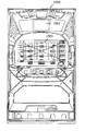
例えば、図23に示すように、特別図柄の変動表示を行う表示装置1001とその他の演出用の表示を行う表示装置1002とを備えるスロットマシン1000などにおいては、いずれの表示装置に本願発明にかかる特別図柄の停止時の戻り表示及びアニメーション表示を実行させるようにしてもよい。
For example, as shown in FIG. 23, in a
さらに、パチンコ遊技機1やスロットマシンの動作をシミュレーションするゲーム機などにも本発明を適用することができる。また、特別図柄(識別情報)の変動開始条件が成立する契機としては、例えば、スロットマシンにおけるスロットレバーの押下、2種や3種のパチンコ遊技機における図柄変動の開始条件の成立などを広く含むものである。また、本発明を実現するためのプログラム及びデータは、コンピュータ装置等に対して、着脱自在の記録媒体により配布・提供される形態に限定されるものではなく、予めコンピュータ装置等の有する記憶装置にプリインストールしておくことで配布される形態を採っても構わない。さらに、本発明を実現するためのプログラム及びデータは、通信処理部を設けておくことにより、通信回線等を介して接続されたネットワーク上の、他の機器からダウンロードすることによって配布する形態を採っても構わない。
Further, the present invention can also be applied to a game machine that simulates the operation of the
そして、ゲームの実行形態も、着脱自在の記録媒体を装着することにより実行するものだけではなく、通信回線等を介してダウンロードしたプログラム及びデータを、内部メモリ等にいったん格納することにより実行可能とする形態、通信回線等を介して接続されたネットワーク上における、他の機器側のハードウェア資源を用いて直接実行する形態としてもよい。さらには、他のコンピュータ装置等とネットワークを介してデータの交換を行うことによりゲームを実行するような形態とすることもできる。 The game execution mode is not only executed by attaching a detachable recording medium, but can also be executed by temporarily storing the downloaded program and data via a communication line or the like in an internal memory or the like. It is also possible to execute directly using hardware resources on the other device side on a network connected via a communication line or the like. Furthermore, the game can be executed by exchanging data with other computer devices or the like via a network.
1 … パチンコ遊技機(遊技機)
2 … 遊技盤(ゲージ盤)
3 … 遊技機用枠(台枠)
4 … 変動表示装置
6 … 普通可変入賞球装置
7 … 特別可変入賞球装置
8L、8R … スピーカ
9 … ランプ
1 ... Pachinko machine (game machine)
2… Game board (gauge board)
3 ... Frame for gaming machines (underframe)
4 ... Fluctuating
Claims (4)
前記複数種類の識別情報のそれぞれを、複数の表示態様で表示するための画像データを記憶する画像データ記憶手段と、
前記画像データ記憶手段に記憶された前記識別情報の種類と配列を特定するための識別情報配列特定情報と各識別情報の表示態様の変化の順番を特定するための画像変化特定情報とを記憶する特定データ記憶手段と、
前記画像表示装置上の識別情報の変動速度と、前記画像表示装置上の該識別情報の変動方向とを指定する変動速度方向指定手段と、
前記画像表示装置上で、識別情報を表示するための表示領域の大きさを特定する表示領域特定手段と、
前記特定データ記憶手段に記憶されている前記識別情報配列特定情報により特定される識別情報の配列と前記画像変化特定情報により特定される各識別情報の表示態様の変化の順番とに従って、前記画像データ記憶手段に記憶されている複数種類の識別情報の画像データをマトリクス状に展開する展開手段と、
前記変動速度方向指定手段により指定された変動速度及び変動方向と前記表示領域特定手段により特定された大きさとに基づいて、前記展開手段が展開したマトリクス状の画像データ上で、前記画像表示装置上の表示領域内の表示対象の画像データを特定する画像データ特定手段と、
識別情報の変動表示結果となる停止識別情報を決定する停止識別情報決定手段と、
を備え、
前記変動速度方向指定手段は、
識別情報の変動方向として予め定めた第1の変動方向と前記第1の変動方向の戻り方向となる第2の変動方向を指定し、
識別情報が第2の変動方向に変動する際の戻り位置を識別情報毎に指定する識別情報毎の戻り位置データと、前記停止識別情報決定手段により決定された停止識別情報の停止位置を指定する停止位置データと、を記憶する制御データ記憶手段を更に備え、
前記変動表示制御手段は、
前記第1変動方向に基づいて前記画像データ特定手段により特定された画像データを読み出して表示画像を生成し、前記画像表示装置に出力する処理を順次繰り返すことにより、第1の変動方向へ変動する識別情報の変動表示処理を行い、
前記停止識別情報決定手段により決定された識別情報で停止する際には、前記第2変動方向と停止する識別情報に応じた戻り位置データとに基づいて前記画像データ特定手段により特定される画像データを読み出して表示画像を生成し、前記画像表示装置に出力する処理を順次繰り返すことにより、識別情報に応じた戻り位置まで第2の変動方向へ変動する識別情報の変動表示を行った後、前記第1の変動方向と停止位置データとに基づいて前記画像データ特定手段により特定された画像データを読み出して、表示画像を生成し、前記画像表示装置に出力する処理を順次繰り返すことにより、停止位置まで第1の変動方向へ変動する識別情報の変動表示処理を行う、
ことを特徴とする遊技機。 The establishment of a predetermined variation starting condition, a Bei obtain game machine variable display control means for displaying the fluctuation of the identification information of a plurality of types can be identified is each image display device,
Image data storage means for storing image data for displaying each of the plurality of types of identification information in a plurality of display modes;
The identification information arrangement specifying information for specifying the type and arrangement of the identification information stored in the image data storage means and the image change specifying information for specifying the order of change in the display mode of each identification information are stored. Specific data storage means;
And changing speed of the identification information on the image display device, the fluctuation velocity direction designation means for designating a fluctuation direction of identification information on the image display device,
On the image display device, a display area specifying means for specifying the size of the display area for displaying the identification information,
Accordance with the order of the change of the display mode of the identification information specified by the sequence and the image change certain information in the identification information specified by the identification information sequence identification information stored before Symbol specific data storage means, the image Expansion means for expanding image data of a plurality of types of identification information stored in the data storage means in a matrix;
Based on the fluctuation speed and fluctuation direction designated by the fluctuation speed direction designation means and the size specified by the display area specification means, the matrix display image data developed by the development means on the image display device Image data specifying means for specifying image data to be displayed within the display area;
A stop identification information determining means for determining the variable display results Do that stop identification information of,
With
The fluctuating speed direction specifying means includes
Specifies the second variation direction a predetermined first fluctuation direction before Symbol return direction of the first variation direction variation direction of the identification information,
A return position data for each identification information for specifying a return position when the identification information is changed to the second variation direction for each identification information, the stop position of the stop identification information determined by the stop identification information determination means further comprising a control data storage means to store the stopping position data specifying a,
The variation display control means includes
By generating the display image by reading the image data specified sequentially repeats the processing to be output to the image display apparatus by the first variation direction before Symbol image data specifying means based on the direction, the first changeable direction Fluctuating display processing of fluctuating identification information,
When stopping at the identification information determined by the stop identification information determination means is specified by the previous SL image data specifying means based on the previous SL return position data corresponding to the second variation Direction and identification information to stop that the image data by reading the display image is generated by sequentially repeating the process of outputting to said image display device, lines Tsu variable display of the identification information that varies the second variation direction to a return position corresponding to the identification information and then reads out the image data specified by the previous SL image data specifying means based on the first variation direction and stopping position data, generates a display image, sequentially a process of outputting to said image display device by repeating performs variable display processing of the identification information that varies to the first variation direction to a stop position,
A gaming machine characterized by that.
前記画像データ記憶手段は、各識別情報について、第1表示画像の画像データと、第2表示画像の画像データとを記憶し、
前記展開手段は、各前記識別情報について、変動表示の開始から変動の停止までの間で、所定の演出表示条件が成立した後で前記画像表示装置に所定の演出表示を行うための演出表示期間には、 表示対象の識別情報について前記第1の表示画像の画像データのみを展開し、変動表示の開始から変動の停止までの間の前記演出表示期間以外の通常表示期間には、前記第1と第2の表示画像の画像データを展開し、
前記変動表示制御手段は、前記通常表示期間には、前記画像データ特定手段により特定される第1と第2の表示画像の画像データを前記画像データ記憶手段より読み出して表示画像を生成し、画像表示装置に出力する処理を順次繰り返し、前記演出表示期間には、前記特定手段により特定される第1の表示画像の画像データを前記画像データ記憶手段より読み出して表示画像を生成し、画像表示装置に出力する処理を順次繰り返す、
ことを特徴とする請求項1に記載の遊技機。 Each said identification information is comprised from two display images of the 1st display image and the 2nd display image which were matched previously ,
The image data storage means stores, for each identification information, image data of the first display image and image data of the second display image,
The expansion means provides an effect display period for performing a predetermined effect display on the image display device after a predetermined effect display condition is established between the start of change display and the stop of change for each of the identification information. For the display target identification information, only the image data of the first display image is developed, and in the normal display period other than the effect display period from the start of the change display to the stop of the change, the first display image is displayed . And expand the image data of the second display image ,
The variable display control means, wherein the normal display period, generates a display image of image data of the first and second display images that will be identified by reading from the image data storage means by the image data specifying means, image sequentially repeating a process of outputting to the display device, wherein the effect display period, the image data of the first display image that will be identified by reading from the image data storage means generates a display image by the specifying unit, an image display device Repeat the process of outputting to
The gaming machine according to claim 1 .
所定の変動開始条件の成立により、各々が識別可能な複数種類の識別情報の変動を画像表示装置に表示する変動表示制御手段を備える遊技機として機能させるコンピュータプログラムであって、
該コンピュータプログラムはコンピュータを、
前記複数種類の識別情報のそれぞれを、複数の表示態様で表示するための画像データを記憶する画像データ記憶手段、
前記画像データ記憶手段に記憶された前記識別情報の種類と配列を特定するための識別情報配列特定情報と各識別情報の表示態様の変化の順番を特定するための画像変化特定情報とを記憶する特定データ記憶手段、
前記画像表示装置上の識別情報の変動速度と、前記画像表示装置上の該識別情報の変動方向とを指定する変動速度方向指定手段、
前記画像表示装置上で、識別情報を表示するための表示領域の大きさを特定する表示領域特定手段、
前記特定データ記憶手段に記憶されている前記識別情報配列特定情報により特定される識別情報の配列と前記画像変化特定情報により特定される各識別情報の表示態様の変化の順番とに従って、前記画像データ記憶手段に記憶されている複数種類の識別情報の画像データをマトリクス状に展開する展開手段、
前記変動速度方向指定手段により指定された変動速度及び変動方向と前記表示領域特定手段により特定された大きさとに基づいて、前記展開手段が展開したマトリクス状の画像データ上で、前記画像表示装置上の表示領域内の表示対象の画像データを特定する画像データ特定手段、
識別情報の変動表示結果となる停止識別情報を決定する停止識別情報決定手段、
として機能させ、
前記変動速度方向指定手段が、
識別情報の変動方向として予め定めた第1の変動方向と前記第1の変動方向の戻り方向となる第2の変動方向を指定し、
識別情報が第2の変動方向に変動する際の戻り位置を識別情報毎に指定する識別情報毎の戻り位置データと、前記停止識別情報決定手段により決定された停止識別情報の停止位置を指定する停止位置データと、を記憶する制御データ記憶手段を更に備えるように機能させ、
前記変動表示制御手段が、
前記第1変動方向に基づいて前記画像データ特定手段により特定された画像データを読み出して表示画像を生成し、前記画像表示装置に出力する処理を順次繰り返すことにより、第1の変動方向へ変動する識別情報の変動表示処理を行い、
前記停止識別情報決定手段により決定された識別情報で停止する際には、前記第2変動方向と停止する識別情報に応じた戻り位置データとに基づいて前記画像データ特定手段により特定される画像データを読み出して表示画像を生成し、前記画像表示装置に出力する処理を順次繰り返すことにより、識別情報に応じた戻り位置まで第2の変動方向へ変動する識別情報の変動表示を行った後、前記第1の変動方向と停止位置データとに基づいて前記画像データ特定手段により特定された画像データを読み出して、表示画像を生成し、前記画像表示装置に出力する処理を順次繰り返すことにより、停止位置まで第1の変動方向へ変動する識別情報の変動表示処理を行うように機能させる、
ようにコンピュータを制御するコンピュータプログラム。 Computer
The establishment of a predetermined variation starting condition, a computer program to function as a game machine to obtain Bei variable display control means for displaying each of the fluctuations of the identification information of a plurality of types can be identified in an image display device,
The computer program is a computer,
Image data storage means for storing image data for displaying each of the plurality of types of identification information in a plurality of display modes;
The identification information arrangement specifying information for specifying the type and arrangement of the identification information stored in the image data storage means and the image change specifying information for specifying the order of change in the display mode of each identification information are stored. Specific data storage means,
It said image display and change the speed of the identification information on the device fluctuation velocity direction designation means for designating a fluctuation direction of identification information on the image display device,
Wherein the image display device on a display area specifying means for specifying the size of the display area for displaying the identification information,
Accordance with the order of the change of the display mode of the identification information specified by the sequence and the image change certain information in the identification information specified by the identification information sequence identification information stored before Symbol specific data storage means, the image Expansion means for expanding image data of a plurality of types of identification information stored in the data storage means in a matrix;
Based on the fluctuation speed and fluctuation direction designated by the fluctuation speed direction designation means and the size specified by the display area specification means, the matrix display image data developed by the development means on the image display device Image data specifying means for specifying image data to be displayed in the display area of
Stop the identification information determining means for determining the variable display results Do that stop identification information of identification information,
Function as
The fluctuating speed direction specifying means is
Specifies the second variation direction as the first change direction before Symbol return direction first variation direction determined in advance as a change direction of the identification information,
A return position data for each identification information identification information to specify a return position when varying the second variation direction for each identification information, stopping of the stop identification stop identification information determined by the determining means And a control data storage means for storing stop position data for designating a position ,
The variation display control means is
By the first reading the image data specified to generate a display image by the previous SL image data specifying means based on the change direction, sequentially repeating a process of outputting to said image display device, variations to the first variation direction Process to change the identification information
When stopping at the identification information determined by the stop identification information determining means, image specified by the previous SL image data specifying means based on the return position data corresponding to the identification information to stop the second variation direction reading data to generate a display image, said by sequentially repeating a process of outputting to the image display device, and Tsu row variable display of the identification information fluctuate to a second variation direction to a return position corresponding to the identification information after, before SL reads the image data specified by the previous SL image data specifying means based on the first variation direction and the stop position data to generate a display image, a process of outputting to said image display device sequentially it allows to function to perform variable display processing of the identification information that varies to the first variation direction to a stop position to repeat,
Computer program to control the computer.
Priority Applications (1)
| Application Number | Priority Date | Filing Date | Title |
|---|---|---|---|
| JP2004000698A JP4217162B2 (en) | 2004-01-05 | 2004-01-05 | Game machine |
Applications Claiming Priority (1)
| Application Number | Priority Date | Filing Date | Title |
|---|---|---|---|
| JP2004000698A JP4217162B2 (en) | 2004-01-05 | 2004-01-05 | Game machine |
Publications (3)
| Publication Number | Publication Date |
|---|---|
| JP2005192719A JP2005192719A (en) | 2005-07-21 |
| JP2005192719A5 JP2005192719A5 (en) | 2006-06-22 |
| JP4217162B2 true JP4217162B2 (en) | 2009-01-28 |
Family
ID=34816406
Family Applications (1)
| Application Number | Title | Priority Date | Filing Date |
|---|---|---|---|
| JP2004000698A Expired - Fee Related JP4217162B2 (en) | 2004-01-05 | 2004-01-05 | Game machine |
Country Status (1)
| Country | Link |
|---|---|
| JP (1) | JP4217162B2 (en) |
Families Citing this family (5)
| Publication number | Priority date | Publication date | Assignee | Title |
|---|---|---|---|---|
| JP5515618B2 (en) * | 2009-10-23 | 2014-06-11 | 株式会社三洋物産 | Game machine |
| JP5928514B2 (en) * | 2014-04-03 | 2016-06-01 | 株式会社三洋物産 | Game machine |
| JP6119903B2 (en) * | 2016-04-27 | 2017-04-26 | 株式会社三洋物産 | Game machine |
| JP2017104757A (en) * | 2017-03-28 | 2017-06-15 | 株式会社三洋物産 | Game machine |
| JP2019092967A (en) * | 2017-11-27 | 2019-06-20 | 株式会社ソフイア | Game machine |
-
2004
- 2004-01-05 JP JP2004000698A patent/JP4217162B2/en not_active Expired - Fee Related
Also Published As
| Publication number | Publication date |
|---|---|
| JP2005192719A (en) | 2005-07-21 |
Similar Documents
| Publication | Publication Date | Title |
|---|---|---|
| JP2005066176A (en) | Game machine | |
| JP2003320105A (en) | Game machine | |
| JP2005218592A (en) | Game machine | |
| JP4217162B2 (en) | Game machine | |
| JP4217163B2 (en) | Game machine | |
| JP4124356B2 (en) | Game machine | |
| JP6276946B2 (en) | Game machine | |
| JP4726410B2 (en) | Game machine | |
| JP2004267483A (en) | Game machine and game control method | |
| JP4217169B2 (en) | Game machine | |
| JP2005066030A (en) | Game machine | |
| JP4217145B2 (en) | Game machine | |
| JP2008229000A (en) | Image generator, game machine and program | |
| JP2002239148A (en) | Game machine and character image displaying method | |
| JP2004008590A (en) | Game machine | |
| JP2000229153A (en) | Image display device for game machine | |
| JP4756826B2 (en) | Game machine | |
| JP2002066039A (en) | Game machine | |
| JP2001231953A (en) | Special design displaying method of game machine | |
| JP2002306724A (en) | Game machine | |
| JP2002066040A (en) | Game machine | |
| JP2005237758A (en) | Game machine | |
| JP2002066037A (en) | Game machine | |
| JP2002066038A (en) | Game machine | |
| JP2002066014A (en) | Game machine |
Legal Events
| Date | Code | Title | Description |
|---|---|---|---|
| A521 | Written amendment |
Free format text: JAPANESE INTERMEDIATE CODE: A523 Effective date: 20060426 |
|
| A131 | Notification of reasons for refusal |
Free format text: JAPANESE INTERMEDIATE CODE: A131 Effective date: 20070828 |
|
| A521 | Written amendment |
Free format text: JAPANESE INTERMEDIATE CODE: A523 Effective date: 20071029 |
|
| TRDD | Decision of grant or rejection written | ||
| A01 | Written decision to grant a patent or to grant a registration (utility model) |
Free format text: JAPANESE INTERMEDIATE CODE: A01 Effective date: 20081104 |
|
| A01 | Written decision to grant a patent or to grant a registration (utility model) |
Free format text: JAPANESE INTERMEDIATE CODE: A01 |
|
| A61 | First payment of annual fees (during grant procedure) |
Free format text: JAPANESE INTERMEDIATE CODE: A61 Effective date: 20081107 |
|
| R150 | Certificate of patent or registration of utility model |
Ref document number: 4217162 Country of ref document: JP Free format text: JAPANESE INTERMEDIATE CODE: R150 Free format text: JAPANESE INTERMEDIATE CODE: R150 |
|
| FPAY | Renewal fee payment (event date is renewal date of database) |
Free format text: PAYMENT UNTIL: 20111114 Year of fee payment: 3 |
|
| FPAY | Renewal fee payment (event date is renewal date of database) |
Free format text: PAYMENT UNTIL: 20111114 Year of fee payment: 3 |
|
| FPAY | Renewal fee payment (event date is renewal date of database) |
Free format text: PAYMENT UNTIL: 20111114 Year of fee payment: 3 |
|
| FPAY | Renewal fee payment (event date is renewal date of database) |
Free format text: PAYMENT UNTIL: 20111114 Year of fee payment: 3 |
|
| FPAY | Renewal fee payment (event date is renewal date of database) |
Free format text: PAYMENT UNTIL: 20121114 Year of fee payment: 4 |
|
| R250 | Receipt of annual fees |
Free format text: JAPANESE INTERMEDIATE CODE: R250 |
|
| FPAY | Renewal fee payment (event date is renewal date of database) |
Free format text: PAYMENT UNTIL: 20121114 Year of fee payment: 4 |
|
| FPAY | Renewal fee payment (event date is renewal date of database) |
Free format text: PAYMENT UNTIL: 20131114 Year of fee payment: 5 |
|
| R250 | Receipt of annual fees |
Free format text: JAPANESE INTERMEDIATE CODE: R250 |
|
| R250 | Receipt of annual fees |
Free format text: JAPANESE INTERMEDIATE CODE: R250 |
|
| R250 | Receipt of annual fees |
Free format text: JAPANESE INTERMEDIATE CODE: R250 |
|
| R250 | Receipt of annual fees |
Free format text: JAPANESE INTERMEDIATE CODE: R250 |
|
| R250 | Receipt of annual fees |
Free format text: JAPANESE INTERMEDIATE CODE: R250 |
|
| R250 | Receipt of annual fees |
Free format text: JAPANESE INTERMEDIATE CODE: R250 |
|
| R250 | Receipt of annual fees |
Free format text: JAPANESE INTERMEDIATE CODE: R250 |
|
| LAPS | Cancellation because of no payment of annual fees |