JP4161573B2 - Parking assistance device - Google Patents
Parking assistance device Download PDFInfo
- Publication number
- JP4161573B2 JP4161573B2 JP2001399992A JP2001399992A JP4161573B2 JP 4161573 B2 JP4161573 B2 JP 4161573B2 JP 2001399992 A JP2001399992 A JP 2001399992A JP 2001399992 A JP2001399992 A JP 2001399992A JP 4161573 B2 JP4161573 B2 JP 4161573B2
- Authority
- JP
- Japan
- Prior art keywords
- vehicle
- distance
- parking
- driver
- initial stop
- Prior art date
- Legal status (The legal status is an assumption and is not a legal conclusion. Google has not performed a legal analysis and makes no representation as to the accuracy of the status listed.)
- Expired - Fee Related
Links
Images


Classifications
-
- G—PHYSICS
- G08—SIGNALLING
- G08G—TRAFFIC CONTROL SYSTEMS
- G08G1/00—Traffic control systems for road vehicles
-
- B—PERFORMING OPERATIONS; TRANSPORTING
- B60—VEHICLES IN GENERAL
- B60T—VEHICLE BRAKE CONTROL SYSTEMS OR PARTS THEREOF; BRAKE CONTROL SYSTEMS OR PARTS THEREOF, IN GENERAL; ARRANGEMENT OF BRAKING ELEMENTS ON VEHICLES IN GENERAL; PORTABLE DEVICES FOR PREVENTING UNWANTED MOVEMENT OF VEHICLES; VEHICLE MODIFICATIONS TO FACILITATE COOLING OF BRAKES
- B60T8/00—Arrangements for adjusting wheel-braking force to meet varying vehicular or ground-surface conditions, e.g. limiting or varying distribution of braking force
- B60T8/17—Using electrical or electronic regulation means to control braking
- B60T8/172—Determining control parameters used in the regulation, e.g. by calculations involving measured or detected parameters
-
- B—PERFORMING OPERATIONS; TRANSPORTING
- B62—LAND VEHICLES FOR TRAVELLING OTHERWISE THAN ON RAILS
- B62D—MOTOR VEHICLES; TRAILERS
- B62D15/00—Steering not otherwise provided for
- B62D15/02—Steering position indicators ; Steering position determination; Steering aids
- B62D15/027—Parking aids, e.g. instruction means
- B62D15/028—Guided parking by providing commands to the driver, e.g. acoustically or optically
-
- B—PERFORMING OPERATIONS; TRANSPORTING
- B60—VEHICLES IN GENERAL
- B60T—VEHICLE BRAKE CONTROL SYSTEMS OR PARTS THEREOF; BRAKE CONTROL SYSTEMS OR PARTS THEREOF, IN GENERAL; ARRANGEMENT OF BRAKING ELEMENTS ON VEHICLES IN GENERAL; PORTABLE DEVICES FOR PREVENTING UNWANTED MOVEMENT OF VEHICLES; VEHICLE MODIFICATIONS TO FACILITATE COOLING OF BRAKES
- B60T2201/00—Particular use of vehicle brake systems; Special systems using also the brakes; Special software modules within the brake system controller
- B60T2201/10—Automatic or semi-automatic parking aid systems
Description
【0001】
【発明の属する技術分野】
この発明は、駐車支援装置に係り、特に駐車の際の運転操作を運転者に案内する装置に関する。
【0002】
【従来の技術】
従来、車両の駐車時に初期停止位置に停止した状態でテレビ画面に車両の後方視界を写し出し、駐車するために必要な運転操作の案内情報をテレビ画面上に重畳表示する支援装置がある。このような装置によれば、テレビ画面に表示された案内情報に従って運転操作を行うだけで容易に駐車をすることができる。
ただし、テレビ画面を見ながら駐車運転を行うのでは運転者に負担がかかるため、音等によって案内情報を出すことが提案されている。このようにすれば、テレビ画面を注視する必要がなくなり、運転者の負担が軽減される。
【0003】
【発明が解決しようとする課題】
しかしながら、初期停止位置から駐車完了までの案内情報を音等により運転者に提供するのでは、初期停止位置が予め設定された基準位置からズレていた場合に、そのズレを解消することができず、駐車の精度が低くなる虞があった。
この発明はこのような問題点を解消するためになされたもので、予め設定された初期停止の基準位置に車両を正確に停止させなくても運転操作を的確に案内して精度の高い駐車支援をすることができる駐車支援装置を提供することを目的とする。
【0004】
【課題を解決するための手段】
この発明に係る駐車支援装置は、車両の側方の障害物までの距離を測定する第1の距離センサと、車両の移動距離を測定する第2の距離センサと、車両のヨー角を検出するためのヨー角検出手段と、運転者に運転操作の案内情報を出力するための案内手段と、前進動作の際に第1の距離センサで測定された車両の側方の障害物までの距離と第2の距離センサで測定された車両の移動距離とを履歴保存し、この履歴に基づいて、目標とする駐車スペースの長さを計測し且つ目標とする駐車スペースに対する車両の傾きを演算すると共にこの傾きに応じて目標とする駐車スペースに駐車するための適切な初期停止位置を演算し、第2の距離センサで測定された車両の移動距離に基づいて初期停止位置に至るように案内手段を介して運転者に案内し、初期停止位置とヨー角検出手段で検出されたヨー角とに基づいて後退駐車をする一旦停止の適正なタイミングを案内手段を介して運転者に提供するコントローラとを備えたものである。
【0005】
なお、一定の操舵角に保持した状態で車両を移動させたときに車両が障害物に干渉すると予測される場合にコントローラが運転者に警報を発するようにしてもよい。
また、コントローラは、初期停止位置までの前進動作の際に第1の距離センサで測定された車両の側方の障害物までの距離と第2の距離センサで測定された車両の移動距離とに基づいて初期停止位置に至ったと判断したときに案内手段を介して運転者に停止する旨を案内するようにしてもよい。
コントローラは、初期停止位置から操舵角を最大にして車両を前進させて後退開始位置で停止させ、後退開始位置から操舵角を逆方向に最大にして車両を後退させて切り返し位置で停止させ、切り返し位置から操舵角を再び逆方向に最大にして車両を後退させて目標とする駐車スペースに至るように案内手段を介して案内情報を運転者に提供することができる。
【0006】
また、コントローラは、初期停止位置から操舵角を最大にして車両を後退させて切り返し位置で停止させ、切り返し位置から操舵角を逆方向に最大にして車両を後退させて目標とする駐車スペースに至るように案内手段を介して案内情報を運転者に提供することができる。
【0007】
第1の距離センサとしては超音波センサあるいは電磁波を利用したセンサ、第2の距離センサとしては車輪速センサをそれぞれ使用することができる。
【0008】
【発明の実施の形態】
以下、この発明の実施の形態を添付図面に基づいて説明する。
実施の形態1.
図1にこの発明の実施の形態1に係る駐車支援装置の構成を示す。コントローラ1には、車両のヨー角方向の角速度を検出するヨーレートセンサ2が接続されると共に、車両が並列駐車を行うことをコントローラ1に知らせるための並列モードスイッチ3と車両が縦列駐車を行うことをコントローラ1に知らせるための縦列モードスイッチ4とからなるスイッチモジュール5が接続されている。さらに、コントローラ1には、運転者に対して運転操作の情報を案内するための案内手段としてスピーカ6が接続されている。
また、コントローラ1には、車両の側方の障害物までの距離を測定する第1の距離センサとしての超音波センサ7と車両の移動距離を測定する第2の距離センサとしての車輪速センサ8とが接続されている。車輪速センサ8は、車両の車輪の回転速度を検出するものであるが、コントローラ1により車輪速センサ8からの信号に基づいて車両の移動距離を演算することができる。
スイッチモジュール5及びスピーカ6は運転席に配置されており、超音波センサ7は車両の前端側部に設置されている。
【0009】
コントローラ1は、図示しないCPUと制御プログラムを記憶したROMと作業用のRAMとを備えている。
ROMには、車両のハンドルが最大に操舵されて車両が旋回する場合の最小旋回半径Rcのデータが記憶されると共に並列駐車時及び縦列駐車時の駐車支援を行う制御プログラムが格納されている。CPUはROMに記憶された制御プログラムに基づいて動作する。コントローラ1は、ヨーレートセンサ2から入力される車両の角速度から車両のヨー角を算出し、車両の旋回角度を算出して駐車運転中の各ステップにおける操作方法や操作タイミングに関する情報をスピーカ6に出力する。
【0010】
ここで、図2を用いて、この実施の形態の駐車支援装置が車両にどのような軌跡を描かせて縦列駐車を支援するのかを説明する。
車両10のリヤ左端が駐車枠Tの奥のコーナーS2に一致するように、車両10を駐車枠Tに駐車するものとする。この状態の車両位置M1における車両10のリヤアクスル中心MOを原点とし、道路と平行で車両10の後退方向にY軸をとり、Y軸と直角にX軸をとる。また、駐車枠Tの奥のコーナーの座標をS2(W2/2,a2)とする。ここで、a2、W2は、車両10のリヤオーバハング、車幅をそれぞれ示す。
車両位置J1にある車両10が、ハンドルの操舵角を右側最大にして半径Rcで旋回しつつ前進し、車両位置K1になったところで、操舵角を左側最大にして半径Rcで旋回しつつ後退し、車両位置L1になったところで操舵角を右側最大にして半径Rcで旋回しつつ後退し、駐車枠T内の車両位置M1に適正に駐車するものとする。
【0011】
まず、駐車枠Tの前方の所定位置に駐車中の車両20を目安にして、車両10を車両位置J1に停車した状態を初期停車位置として、縦列駐車を開始するものとする。
車両位置J1は、車両10の運転者の位置DRのY座標が駐車中の車両20の後端20aのY座標に一致する位置で且つ駐車枠Tに平行な位置であり並びに車両10と車両20とが所定の車両間隔dである位置とする。したがって、車両位置J1のリヤアクスル中心JOの座標(JOx,JOy)は、車両20の後端部20aの座標と運転者の位置DRとリヤアクスル中心JOとの関係および車両間隔dから一義的に定められる。
車両位置J1にある車両10が、ハンドルの操舵角を右側最大にして半径Rcで旋回しつつ車両位置K1まで前進する。その際の旋回中心をC3とし、旋回角度をβとする。また、車両位置K1にある車両10が操舵角を左側最大にして半径Rcで旋回しつつ車両位置L1まで後退する。その際の旋回中心をC4とし、旋回角度をδとする。さらに、車両位置L1でハンドルを反対方向に切り返して、操舵角を右側最大にして半径Rcで旋回しつつ車両位置M1まで後退する。その際の旋回中心をC5とし、旋回角度をαとする。
また、車両位置K1,L1におけるリヤアクスル中心をそれぞれKO,LOとする。
【0012】
旋回角度α,β,δには、
δ=α−β
の関係がある。
旋回中心C5の座標(C5x,C5y)は、
C5x=−Rc
C5y=0
で表される。
旋回中心C4の座標(C4x,C4y)は、
C4x=C5x+(Rc+Rc)・cosα=−Rc+2Rc・cosα
C4y=C5y−(Rc+Rc)・sinα=−2Rc・sinα
で表される。
旋回中心C3の座標(C3x,C3y)は、
C3x=C4x−(Rc+Rc)・cosβ=−Rc+2Rc・cosα−2Rc・cosβ
C3y=C4y+(Rc+Rc)・sinβ=−2Rc・sinα+2Rc・sinβ
で表される。
また、車両位置J1のリヤアクスル中心JOの座標(JOx,JOy)は、
JOx =−Rc・(1−cosα)−Rc・(1−cosα−1+cosβ)+Rc・(1−cosβ)
=2Rc・(cosα−cosβ) ……………(1)
JOy =−Rc・sinα−Rc・(sinα−sinβ)+Rc・sinβ
=2Rc・(sinβ−sinα) ……………(2)
で表される。
【0013】
ここで、式(1)及び(2)を三角関数の公式を用いて、変形すると、
tan(α/2+β/2)=JOx/JOy
sin2(α/2−β/2)=(JOx2+JOy2)/(16Rc2)
となり、α、βを、既知のリヤアクスル中心JOの座標(JOx,JOy)を用いて算出することができる。
リヤアクスル中心JOの座標(JOx,JOy)は、車両10を車両20の後方に無理のない操作で駐車できる標準的な値として、例えば、JOx=2.3m、JOy=4.5mの値が設定されている。
リヤアクスル中心JOの標準的な座標JOxおよびJOyは、車両10の車格、操舵特性などに応じて値を設定することが望ましい。
【0014】
次に、実施の形態1に係る駐車支援装置の縦列駐車時の動作について説明する。
まず、図3に示されるように、道路と平行に、すなわち目標とする駐車枠Tに平行に車両10を直進前進させて、運転者の位置DRのY座標が駐車中の車両20の後端20aのY座標に一致し、車両10が車両20に対して車両間隔d、例えば50cmとなるような車両位置J1へと向かう。このとき、前進しながら、車両の前端側部に設置されている超音波センサ7により車両側方の障害物、例えば駐車中の車両20までの距離の測定が連続して行われる。車両10は次第に車両位置J1に接近し、図4に示されるように、運転者の位置DRのY座標が駐車中の車両20の後端20aのY座標に一致する位置にまで至る。
【0015】
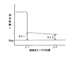
ここで、車両10の前進に伴って、超音波センサ7の位置に対応した障害物までの測定距離xは図5のように示される。目標となる駐車枠Tには車両が存在しないので、この駐車枠Tの側方を通るときには測定距離xは非常に大きな値となるが、図3に示されるように超音波センサ7のY座標が駐車中の車両20の後端20aのY座標に一致する座標y1に到達すると、測定距離xは急激に小さくなって超音波センサ7から車両20までの距離となる。このときの測定距離xは、初期停止の基準位置STである車両20からの間隔50cmとx方向のズレdx1との和で表される。
【0016】
この測定距離xの急激な変化から、コントローラ1は超音波センサ7が座標y1に到達したことを認識することができる。そこで、コントローラ1は、車両10の前端から運転者の位置DRまでの長さLDを予め記憶しておくと共に車輪速センサ8からの信号により演算された車両10の移動距離を監視し、超音波センサ7が座標y1に達したときから車両10が距離LDだけ前進したところでスピーカ6を介して運転者に特定の停止音を発する。この停止音を聞いた運転者は車両10を停止させる。その結果、運転者の位置DRのY座標が駐車中の車両20の後端20aのY座標に一致する位置となり、ここを初期停止位置とする。このときの超音波センサ7による測定距離xは、初期停止の基準位置STである車両20からの間隔50cmとx方向のズレdx2との和で表される。
【0017】
車両10を正確に初期停止の基準位置STに位置させることは困難であるため、上記のようなx方向のズレdx1及びdx2が生じやすくなる。なお、ズレdx1とズレdx2は、車両10が駐車中の車両20に対して平行に走行していれば互いに等しくなるが、ある傾きをもって斜めに走行している場合には互いに異なった値となる。座標y1とy2との間の距離は予めコントローラ1に記憶されているLDであるので、ズレdx1及びdx2と距離LDから、この初期停止位置における車両10の初期停止の基準位置STに対する傾きをも求めることができる。
そこで、初期停止位置に停止した状態で運転者が縦列モードスイッチ4を作動させると、コントローラ1は、このようにして測定されたズレdx1及びdx2およびリヤアクスル中心JOの標準的な座標JOxおよびJOyから、実際の初期停止位置のリヤアクスル中心JO’の座標(JOx+dx,JOy+dy)を得て適正に駐車枠Tに縦列駐車することができるように上記の旋回角度α,β及びδを算出する。
【0018】
また、縦列モードスイッチ4の作動に基づいてコントローラ1は、初期停止位置を車両のヨー角が0度の位置として設定すると共に縦列駐車のためのプログラムを起動させる。運転者は、車両10のハンドルを右側最大に操舵してフル切り状態にし、そのまま車両10を前進させる。コントローラ1は、ヨーレートセンサ2から入力される車両10の角速度から車両のヨー角を算出して、このヨー角と算出された旋回角度βの値とを比較する。車両10が、初期停止位置から後退開始位置である車両位置K1に近づくにつれて、コントローラ1は、ヨー角と算出された旋回角度βとの差を基に、車両位置K1に接近したことを知らせる接近情報と、車両位置K1に到達したことを知らせる到達情報とをスピーカ6を介して運転者に知らせる。
例えば、接近情報として、スピーカ6から「ピッ、ピッ」という間欠音が発せられ、この間欠音及び点滅の周期は、ヨー角と旋回角度βとの差が少なくなると共に短くなる。ヨー角と旋回角度βとの差がなくなると、到達情報として、スピーカ6から「ピー」という連続音が発せられる。
【0019】
運転者は、到達情報に従って車両10を車両位置K1に停止させる。次に、運転者は、ハンドルを左にいっぱい操舵してフル切り状態にし、そのまま車両10を後退させる。コントローラ1は、車両のヨー角と算出された旋回角度α(=β+δ)の値とを比較する。車両10が、車両位置K1から切り返し位置となる車両位置L1に近づくにつれて、すなわち、車両のヨー角が算出された旋回角度αの値に近づくにつれて、コントローラ1は、ヨー角と算出された旋回角度αとの差を基に、車両位置L1に接近したことを知らせる接近情報と、車両位置L1に到達したことを知らせる到達情報とをスピーカ6を介して運転者に知らせる。
【0020】
運転者は、到達情報に従って車両10を車両位置L1に停止させる。次に、運転者は、車両位置L1でハンドルを反対方向に切り返して、右側最大に操舵してフル切り状態にし、そのまま車両10を後退させる。コントローラ1は、車両10のヨー角が0度に近づくにつれて、車両10が目標となる駐車枠T内の車両位置M1に接近したことを知らせる接近情報と、車両位置M1に到達したことを知らせる到達情報とをスピーカ6を介して運転者に知らせる。これにより、運転者は、車両位置M1で車両10を停止させ、駐車を完了することができる。
【0021】
実施の形態2.
実施の形態2に係る駐車支援装置は、図1に示した実施の形態1の駐車支援装置と同様の構成を有しているが、図6に示されるように、目標となる駐車枠Tの前方に車両20が既に駐車しているだけでなく、後方にも車両30が駐車している場合に有効なものである。
まず、駐車枠Tの後方に駐車している車両30の側方から道路と平行に車両10を直進前進させつつ、超音波センサ7により車両側方の障害物までの距離測定を連続して行う。この超音波センサ7による距離測定は、車両10が初期停止位置に至るまで、すなわち運転者の位置DRのY座標が駐車中の車両20の後端20aのY座標に一致する位置に至るまで連続して行われる。
【0022】
このとき、車両10の前進に伴って、超音波センサ7で測定される距離xは図7のように示される。初めは、駐車枠Tの後方に駐車している車両30までの距離が測定されるが、超音波センサ7のY座標が駐車中の車両30の前端30aのY座標に一致する座標y0に到達した後は車両が存在しないので、測定距離xは非常に大きな値となる。さらに、超音波センサ7のY座標が駐車枠Tの前方に駐車している車両20の後端20aのY座標に一致する座標y1に到達すると、測定距離xは急激に小さくなって超音波センサ7から車両20までの距離となる。従って、測定距離xの急激な変化から、コントローラ1は超音波センサ7が座標yo及びy1に到達したことを認識することができ、この間に車両10が移動した距離PSLを車輪速センサ8からの信号によって演算することができる。この距離PSLは、駐車中の車両30と20に形成された駐車スペースの長さを表している。
【0023】
超音波センサ7が座標y1に到達した後は、実施の形態1と同様に、車両10が距離LDだけ前進して超音波センサ7が座標y2に達したところでスピーカ6を介して運転者に特定の停止音を発する。この停止音を聞いた運転者は車両10を停止させる。その結果、運転者の位置DRのY座標が駐車中の車両20の後端20aのY座標に一致する位置となり、ここを初期停止位置とする。
そして、初期停止位置に停止した状態で運転者が縦列モードスイッチ4を作動させると、コントローラ1は、測定されたズレdx1及びdx2と駐車スペースの長さPSLに基づいて、実際の初期停止位置から適正に駐車枠Tに縦列駐車することができるように旋回角度α,β及びδを算出する。
このようにして算出された旋回角度α,β及びδに基づいて、コントローラ1は実施の形態1と同様に、フル切り状態での一旦停止の適正なタイミングをスピーカ6を介して運転者に提供し、これにより運転者は駐車枠Tへの縦列駐車を完了することができる。
【0024】
実施の形態3.
実施の形態3に係る駐車支援装置は、図1に示した実施の形態1の駐車支援装置と同様の構成を有しているが、予め設定された初期停止の基準位置に車両を停止させるのではなく、超音波センサ7により測定された車両側方の障害物までの距離xに基づいてコントローラ1が適切な初期停止位置を演算して運転者に案内するものである。さらに、初期停止位置から操舵角を最大にして車両を後退させて切り返し位置で停止させ、切り返し位置から操舵角を逆方向に最大にして車両を後退させて目標とする駐車スペースに至るような案内情報が運転者に提供される。
【0025】
図8を参照して適切な初期停止位置の演算方法を説明する。車両10と駐車中の車両20との間の車間距離をBとする。これらの車両の幅をそれぞれW2とすると、駐車操作により車両10をX方向に移動させるべき距離DXは、
DX=B+W2
と表される。車両10のリヤアクスル中心が初期停止位置P1におけるP0から切り返し位置Q1におけるQ0まで移動するときの旋回角度をγとし、リヤアクスル中心の最小旋回半径をRcとすると、
DX=2Rc・(1−cosγ)
となる。
ここで、距離DXは超音波センサ7により測定することができ、最小旋回半径Rcは既知であるので、上式から旋回角度γを算出することができる。
旋回角度γが求められると、
DY=2Rc・sinγ
よりリヤアクスル中心の位置P0とR0との間のY方向の距離DYを求めることができる。
【0026】
車両10の旋回の際における駐車中の車両20の右後端Zと車両10の左前端との間の干渉余裕をFとする。なお、図8では、両者が互いに干渉しているので、Fは負の値となる。
車両10の左前端の旋回半径Rflは車両10の全長をLとして、
Rfl={(Rc+W2/2)2+(L−a2)2}1/2
と表される。一方、車両20の右後端Zと車両10の旋回中心C7との間の距離ZC7は、車両20の右後端Zと車両10の旋回中心C7との間のY方向の距離Eを用いて、
ZC7={(Rc−W2/2)2+E2}1/2
となる。
【0027】
干渉余裕Fは、
F=ZC7−Rfl
と表されるので、このFに具体的な数値、例えば40cmを代入することにより、距離Eの値を定めることができる。
ここで、既に距離DYが求められているため、駐車中の車両20の後端から初期停止位置P1の車両10の前端までの前方距離Dは、
D=DY−E+L−a2
となる。このようにして、前方距離Dを車両10と駐車中の車両20との間の車間距離Bから求めることができる。
【0028】
次に、実施の形態3に係る駐車支援装置の縦列駐車時の動作について説明する。
まず、道路と平行に車両10を直進前進させて駐車スペースの側方を通過中に縦列モードスイッチ4を作動させる。これにより、車両10の前端側部に設置されている超音波センサ7によって駐車中の車両20までの距離の測定が連続して行われ、実施の形態1と同様にしてコントローラ1は、超音波センサ7が車両20の後端位置に到達したことを認識すると共に車両10と車両20との間の車間距離Bを測定し、上記の手順に従って、車両20の後端から適切な初期停止位置P1の前端までの前方距離Dとその後の旋回角度γとを確定することができる。
【0029】
コントローラ1は、車輪速センサ8からの信号により演算された車両10の移動距離を監視し、超音波センサ7が駐車中の車両20の後端位置に達したときから車両10が前方距離Dだけ前進したところでスピーカ6を介して運転者に特定の停止音を発する。この停止音を聞いた運転者は車両10を停止させる。その結果、車両10は適切な初期停止位置P1に停止することとなる。このとき、コントローラ1は、ヨーレートセンサ2による車両10のヨー角をリセットする。
【0030】
その後、運転者は、車両10のハンドルを左側最大に操舵してフル切り状態にし、そのまま車両10を後退させる。コントローラ1は、車両のヨー角と確定された旋回角度γの値とを比較し、ヨー角が旋回角度γに接近するとスピーカ6を介して接近情報を出力し、さらにヨー角が旋回角度γになったところで切り返し位置Q1に到達したと判断してスピーカ6を介して到達情報を出力する。
運転者は、到達情報に従って車両10を切り返し位置Q1に停止させ、ここでハンドルを反対方向に切り返して、右側最大に操舵してフル切り状態にし、そのまま車両10を後退させる。コントローラ1は、車両10のヨー角が0度に近づくにつれて、車両10が目標となる駐車スペース内の車両位置R1に接近したことを知らせる接近情報と、車両位置R1に到達したことを知らせる到達情報とをスピーカ6を介して運転者に知らせる。これにより、運転者は、車両位置R1で車両10を停止させ、駐車を完了することができる。
【0031】
なお、駐車中の車両20の後端から適切な初期停止位置P1の前端までの距離Dとその後の旋回角度γの車間距離Bに対する関係は、車両10の特性に基づいて例えば図9に示されるように確定される。
この実施の形態3においても、実施の形態2と同様に、初期停止位置に向かう直進前進の際に目標となる駐車スペースの長さを計測して駐車の可否を案内したり、後方に駐車中の車両等の障害物との干渉を警報したりすることができる。
【0032】
実施の形態4.
この実施の形態4は、実施の形態3において、初期停止位置に向かう直進前進の方向が駐車中の車両20と平行でなく傾き角度εを有する場合に有用なものである。図10に示されるように、角度εだけ傾いて停止した車両10の位置P2は、駐車中の車両20と平行に停止した位置P1から駐車操作により角度εだけ後退した状態と考えることができる。
【0033】
位置P1の車両10が旋回半径Rcで角度εだけ後退して位置P2に至るとすると、位置P2における車両10の左前端の座標(X1f、Y1f)は、旋回中心を原点として位置P1における車両10の左前端の座標(X0f、Y0f)を用いて、
X1f=X0f・cosε+Y0f・sinε
Y1f=Y0f・cosε−X0f・sinε
と表される。従って、
位置P1とP2との間の車両10の左前端のX方向変位ΔX1fは、
ΔX1f=X1f−X0f=Y0f・sinε−X0f・(1−cosε)
となり、実際の車両10のパラメータで表現すると、
ΔX1f=(L−a2)・sinε−(Rc−W2/2)・(1−cosε)
となる。
【0034】
実際の車両10では、例えば図11に示されるように、車両10の前端側部に設置されている超音波センサ7で駐車中の車両20の後端を検出したときの水平距離をA0とすると、この距離A0に対応する車両20に平行な車両の水平距離B0は、
B0=A0−ΔX1f=A0−(L・a2)・sinε+(Rc−W2/2)・(1−cosε)
となる。
【0035】
ところで、傾き角度εは、例えば図12に示されるように、超音波センサ7で駐車中の車両20の後端を検出してからH1だけ進んだときの車両20との車間距離A1と、さらにH2だけ進んだときの車両20との車間距離A2から、
ε=tan-1{(A2−A1)/H2}
で得られる。
【0036】
次に、図13に示されるように、車間距離Bに対する前方距離Dと旋回角度γの関係を示すグラフにおいて、前方距離Dが0のときの車間距離B0の点から延びる傾きεの直線と前方距離Dを表す曲線との交点により、駐車中の車両20と平行な車両に置き換えたときの適切な前方距離Daを求めることができる。さらに、傾きεの直線と前方距離Dを表す曲線との交点からY軸に平行に引いた直線と旋回角度γを表す曲線との交点により、適切な旋回角度γaを求めることができる。
【0037】
図10において、位置P1とP2との間の車両10の左前端のY方向変位ΔY1fは、
ΔY1f=Y1f−Y0f=−{X0f・sinε+Y0f・(1−cosε)}
となり、実際の車両10のパラメータで表現すると、
ΔY1f=−{(Rc−W2/2)・sinε+(L−a2)・(1−cosε)}
となる。
角度εだけ傾いた車両は、駐車中の車両20と平行な車両より上記のY方向変位ΔY1fだけ手前に位置すると考えられるので、前方距離DaからY方向変位ΔY1fを差し引いた距離だけY方向に進めばよく、角度εの斜め方向には次の式で表される距離D1となる。
D1=(Da−ΔY1f)/cosε
=[Da+{(Rc−W2/2)・sinε+(L−a2)・(1−cosε)}]/cosε
【0038】
また、旋回角度γについては、駐車中の車両20と平行な車両から既に角度εだけ旋回しているので、
γ1=γa−ε
で表される角度γ1が角度εだけ傾いた初期停止位置から切り返し位置までの旋回角度となる。
なお、切り返し位置から目標となる駐車スペースまでの旋回角度はγaとなる。
【0039】
そこで、実施の形態3において、初期停止位置に向かう直進前進の方向が駐車中の車両20に対して角度εで傾いていると判定された場合には、超音波センサ7が駐車中の車両20の後端位置に達したときから車両10が上記の距離D1だけ斜めに前進したところで停止し、その初期停止位置からハンドルを左側最大に操舵して角度γ1だけ後退したところで再び停止し、ハンドルを右側最大に切り返して角度γaだけ後退したところで駐車を完了するように運転者に案内情報を出力すればよい。
【0040】
なお、この実施の形態4においても、実施の形態2と同様に、初期停止位置に向かう直進前進の際に目標となる駐車スペースの長さを計測して駐車の可否を案内したり、後方に駐車中の車両等の障害物との干渉を警報したりすることができる。
超音波センサ7による駐車中の車両20との車間距離の測定は、実際には、車両の角の丸みの影響やセンサの特性に応じて補正を行うことが望ましい。
また、距離D1及び角度γ1を幾何学的に求める場合について説明したが、解析的に算出するようにしてもよい。
【0041】
実施の形態5.
実施の形態5は、上述した実施の形態3及び4において、駐車スペースの側方を通過中に縦列モードスイッチ4を作動させることにより駐車中の車両20までの距離の測定を開始する代わりに、超音波センサ7による車両側方の障害物までの距離の測定と車輪速センサ8による車両の走行距離の測定とを常時行って走行距離に応じた車両側方の障害物までの距離を履歴保存し、この履歴を利用して初期停止位置を算出しようとするものである。
【0042】
コントローラ1は、超音波センサ7及び車輪速センサ8を常時作動させ、これらのセンサから入力される信号に基づいて過去の所定時間分あるいは所定走行距離分における走行距離に応じた車両側方の障害物までの距離を履歴保存する。
駐車スペースの側方を通過して適当な位置、例えば実施の形態3及び4の初期停止位置のように駐車中の車両20の側方で車両10を停止させて縦列モードスイッチ4を作動させる。これにより、コントローラ1は、停止前の所定時間分あるいは所定走行距離分における走行距離に応じた車両側方の障害物までの距離の履歴に基づき、実施の形態3あるいは4に記載したような演算方法によって駐車スペースに縦列駐車するための適正な初期停止位置を算出する。
【0043】
初期停止位置が算出されると、コントローラ1は直進前進あるいは直進後退して初期停止位置に至るようにスピーカ6を介して運転者に案内する。
ただし、コントローラ1に保存されている履歴だけでは初期停止位置を算出することができない場合には、さらに直進前進あるいは直進後退するようにスピーカ6を介して運転者に案内し、その間に得られた走行距離と障害物までの距離との関係を保存されている履歴に加味して初期停止位置の算出を行う。その後、コントローラ1は直進前進あるいは直進後退して初期停止位置に至るようにスピーカ6を介して運転者に案内する。
【0044】
このようにして車両10が初期停止位置に停止した後は、コントローラ1は、実施の形態3あるいは4と同様にして、車両10が切り返し位置へ至り、さらに駐車スペースへ至るようにスピーカ6を介して案内情報を運転者に提供する。
なお、この実施の形態5においても、実施の形態2〜4と同様に、初期停止位置に向かう直進前進の際に目標となる駐車スペースの長さを計測して駐車の可否を案内したり、後方に駐車中の車両等の障害物との干渉を警報したりすることができる。
上述した実施の形態5によれば、適当な位置に車両10を停止させて縦列モードスイッチ4を作動させるだけで、過去の履歴に基づき適正な初期停止位置が算出されるので、さらに操作性の優れた駐車支援装置が実現される。
【0045】
実施の形態6.
実施の形態6に係る駐車支援装置の構成を図14に示す。この実施の形態6の駐車支援装置は、図1に示した実施の形態1の装置において、超音波センサ7の代わりに光センサ9を第1の距離センサとして車両の前端側部に設置し、車両の側方の障害物までの距離を測定するものである。
このような実施の形態6によっても、実施の形態1〜5と同様に、フル切り状態での一旦停止の適正なタイミングをスピーカ6を介して運転者に提供し、駐車枠Tへの縦列駐車を完了させることができる。
なお、光センサ9を用いても、実施の形態2と同様に、駐車スペースの長さを計測して旋回角度α,β及びδの算出に役立てることが可能である。
光センサ9は、LEDやレーザダイオード等の発光手段とフォトトランジスタやCCDデバイス等の受光手段との組み合わせから構成することができる。さらに、光センサ9の代わりにレーダー等、光以外の電磁波を利用したセンサでもよい。
【0046】
なお、上述した実施の形態1〜6において、コントローラ1による旋回角度の算出の際に、ズレが大きいために駐車運転に適用し得る旋回角度を算出することができない場合や、最大舵角に保持しつつその旋回角度で車両10を旋回させると、縦列駐車時に車両10が駐車中の車両20等の障害物に干渉することが予測される場合は、スピーカ6を介して運転者に警報を発するように構成することもできる。このようにすれば、初期停止位置の位置ズレを考慮して算出された旋回角度に伴って障害物に干渉することを防止することができる。
【0047】
また、実施の形態1〜6ではヨー角検出手段としてヨーレートセンサを用いたが、ヨー角を検出する手段は、ポジションジャイロを用いる方法や左右車輪にそれぞれ回転センサを装着しそれらの回転差からヨー角を検出する方法でもよく、さらに、地磁気センサやGPSシステムを用いた方法でもよい。
なお、上記の実施の形態1〜6において、接近情報及び到達情報として、接近あるいは到達の目標となる車両位置ごとに、スピーカ6から発する音の音量及び音色を変えたり、内容の異なる音声を発するようにしてもよい。また、案内手段は、スピーカに限られるものではなく、ブザー、LED、ランプでもよく、ディスプレイ上に文字、マークを表示してもよい。さらに、ハンドル等を介して運転者に伝達される振動でもよい。
【0048】
【発明の効果】
以上説明したように、この発明によれば、初期停止位置に至るまでの前進動作の際に第1の距離センサで測定された車両の側方の障害物までの距離と第2の距離センサで測定された車両の移動距離を履歴保存し、この履歴に基づいて目標とする駐車スペースの長さを計測し且つ目標とする駐車スペースに対する車両の傾きを演算すると共にこの傾きに応じて目標とする駐車スペースに駐車するための適切な初期停止位置を演算し、第2の距離センサで測定された車両の移動距離に基づいて初期停止位置に至るように案内手段を介して運転者に案内するので、予め設定された初期停止の基準位置に車両を正確に停止させなくても、運転者に大きな負担をかけることなく駐車の際の運転操作を的確に案内することができる。
さらに、適正な初期停止位置を案内するので、後退駐車の際の操作回数が削減され、運転者の負担をさらに低減することが可能となる。
【図面の簡単な説明】
【図1】 この発明の実施の形態1に係る駐車支援装置の構成を示すブロック図である。
【図2】 実施の形態1における縦列駐車時の車両の位置を段階的且つ模式的に示す図である。
【図3】 実施の形態1における縦列駐車時の初期停止位置に至る手前の地点に車両が位置した状態を示す平面図である。
【図4】 実施の形態1における縦列駐車時の初期停止位置に車両が位置した状態を示す平面図である。
【図5】 実施の形態1における超音波センサの位置に対する測定距離を示すグラフである。
【図6】 実施の形態2における縦列駐車時の各位置に車両が位置した状態を示す平面図である。
【図7】 実施の形態2における超音波センサの位置に対する測定距離を示すグラフである。
【図8】 実施の形態3における縦列駐車時の車両の位置を段階的且つ模式的に示す図である。
【図9】 実施の形態3における駐車中の車両の後端から適切な初期停止位置の前端までの前方距離Dとその後の旋回角度γの車間距離Bに対する関係を示すグラフである。
【図10】 実施の形態4における適切な初期停止位置の演算方法を示す図である。
【図11】 実施の形態4における適切な初期停止位置の演算方法を示す図である。
【図12】 実施の形態4における適切な初期停止位置の演算方法を示す図である。
【図13】 実施の形態4における適切な初期停止位置の演算方法を示す図である。
【図14】 実施の形態6に係る駐車支援装置の構成を示すブロック図である。
【符号の説明】
1 コントローラ、2 ヨーレートセンサ、4 縦列モードスイッチ、6 スピーカ、7 超音波センサ、8 車輪速センサ、9 光センサ、10,20,30 車両、P1 初期停止位置、Q1 切り返し位置、R1 駐車スペース内の車両位置。[0001]
BACKGROUND OF THE INVENTION
The present invention relates to a parking assistance device, and more particularly to a device for guiding a driving operation during parking to a driver.
[0002]
[Prior art]
2. Description of the Related Art Conventionally, there is a support device that projects a rear view of a vehicle on a television screen in a state where the vehicle is parked at an initial stop position when the vehicle is parked, and superimposes and displays driving operation guidance information necessary for parking on the television screen. According to such an apparatus, it is possible to easily park the vehicle simply by performing a driving operation according to the guidance information displayed on the television screen.
However, it is proposed that the guidance information is output by sound or the like because parking the driver while watching the TV screen places a burden on the driver. In this way, it is not necessary to watch the TV screen and the burden on the driver is reduced.
[0003]
[Problems to be solved by the invention]
However, providing guidance information from the initial stop position to the completion of parking to the driver by sound or the like cannot be eliminated when the initial stop position is shifted from a preset reference position. There was a risk that the accuracy of parking would be lowered.
The present invention has been made to solve such problems, and provides high-precision parking assistance by accurately guiding driving operations without stopping the vehicle accurately at a preset initial stop reference position. An object of the present invention is to provide a parking assist device capable of
[0004]
[Means for Solving the Problems]
The parking assist device according to the present invention detects a first distance sensor that measures a distance to an obstacle on a side of the vehicle, a second distance sensor that measures a moving distance of the vehicle, and a yaw angle of the vehicle. A yaw angle detecting means for driving, a guiding means for outputting driving operation guidance information to the driver, and a distance to an obstacle on the side of the vehicle measured by the first distance sensor during forward movement The vehicle travel distance measured by the second distance sensor is saved as a history, and based on this history,Measure the length of the target parking spaceAnd calculating the vehicle's inclination with respect to the target parking space and according to this inclinationAn appropriate initial stop position for parking in the target parking space is calculated, and the driver is guided via the guide means so as to reach the initial stop position based on the moving distance of the vehicle measured by the second distance sensor. And a controller that provides the driver with an appropriate timing of temporary stop through the guide means for guiding and performing reverse parking based on the initial stop position and the yaw angle detected by the yaw angle detection means. .
[0005]
Note that the controller may issue an alarm to the driver when the vehicle is predicted to interfere with an obstacle when the vehicle is moved while being held at a constant steering angle.
Also,The controller is based on the distance to the obstacle on the side of the vehicle measured by the first distance sensor and the moving distance of the vehicle measured by the second distance sensor during the forward movement to the initial stop position. When it is determined that the initial stop position has been reached, the driver may be instructed to stop through the guiding means.
The controller advances the vehicle from the initial stop position with the maximum steering angle and stops at the reverse start position, and from the reverse start position to maximize the steering angle in the reverse direction, reverses the vehicle, stops at the return position, and returns. Guidance information can be provided to the driver via the guide means so that the steering angle is maximized in the opposite direction from the position and the vehicle is moved backward to reach the target parking space.
[0006]
Further, the controller retracts the vehicle from the initial stop position with the maximum steering angle and stops at the return position, and from the return position to maximize the steering angle in the reverse direction to reverse the vehicle to reach the target parking space. So that the guidance information can be provided to the driver via the guidance means..
[0007]
An ultrasonic sensor or an electromagnetic wave sensor can be used as the first distance sensor, and a wheel speed sensor can be used as the second distance sensor.
[0008]
DETAILED DESCRIPTION OF THE INVENTION
Embodiments of the present invention will be described below with reference to the accompanying drawings.
FIG. 1 shows the configuration of a parking assist apparatus according to
The
The switch module 5 and the
[0009]
The
The ROM stores data of a minimum turning radius Rc when the vehicle handle is turned to the maximum and the vehicle turns, and stores a control program for assisting parking in parallel parking and parallel parking. The CPU operates based on a control program stored in the ROM. The
[0010]
Here, with reference to FIG. 2, a description will be given of what kind of locus the parking assistance apparatus of this embodiment draws in the vehicle to support parallel parking.
It is assumed that the
The
[0011]
First, tandem parking is started with the
The vehicle position J1 is a position where the Y coordinate of the position DR of the driver of the
The
Further, the rear axle centers at vehicle positions K1 and L1 are denoted as KO and LO, respectively.
[0012]
The turning angles α, β, δ are
δ = α-β
There is a relationship.
The coordinates (C5x, C5y) of the turning center C5 are
C5x = −Rc
C5y = 0
It is represented by
The coordinates (C4x, C4y) of the turning center C4 are
C4x = C5x + (Rc + Rc) ・ cosα = −Rc + 2Rc ・ cosα
C4y = C5y− (Rc + Rc) ・ sinα = −2Rc ・ sinα
It is represented by
The coordinates (C3x, C3y) of the turning center C3 are
C3x = C4x− (Rc + Rc) ・ cosβ = −Rc + 2Rc ・ cosα−2Rc ・ cosβ
C3y = C4y + (Rc + Rc) ・ sinβ = −2Rc ・ sinα + 2Rc ・ sinβ
It is represented by
The coordinates (JOx, JOy) of the rear axle center JO at the vehicle position J1 are
JOx = -Rc. (1-cos.alpha.)-Rc. (1-cos.alpha.-1 + cos.beta.) + Rc. (1-cos.beta.)
= 2Rc ・ (cosα−cosβ) …………… (1)
JOy = −Rc ・ sinα−Rc ・ (sinα−sinβ) + Rc ・ sinβ
= 2Rc ・ (sinβ−sinα) …………… (2)
It is represented by
[0013]
Here, when the equations (1) and (2) are transformed using the trigonometric formula,
tan (α / 2 + β / 2) = JOx / JOy
sin2(Α / 2-β / 2) = (JOx2+ JOy2) / (16Rc2)
Thus, α and β can be calculated using the coordinates (JOx, JOy) of the known rear axle center JO.
The coordinates (JOx, JOy) of the rear axle center JO are set as standard values that allow the
The standard coordinates JOx and JOy of the rear axle center JO are desirably set in accordance with the vehicle grade, steering characteristics, etc. of the
[0014]
Next, the operation | movement at the time of parallel parking of the parking assistance apparatus which concerns on
First, as shown in FIG. 3, the
[0015]
Here, as the
[0016]
From this sudden change in the measurement distance x, the
[0017]
Since it is difficult to accurately position the
Therefore, when the driver operates the tandem mode switch 4 while stopped at the initial stop position, the
[0018]
Further, based on the operation of the column mode switch 4, the
For example, an intermittent sound “beep” is emitted from the
[0019]
The driver stops the
[0020]
The driver stops the
[0021]
The parking assistance apparatus according to the second embodiment has the same configuration as that of the parking assistance apparatus according to the first embodiment shown in FIG. 1, but as shown in FIG. This is effective not only when the
First, the distance from the side of the
[0022]
At this time, as the
[0023]
After the
When the driver operates the tandem mode switch 4 while stopped at the initial stop position, the
Based on the turning angles α, β, and δ calculated in this way, the
[0024]
The parking assistance apparatus according to the third embodiment has the same configuration as that of the parking assistance apparatus according to the first embodiment shown in FIG. 1, but the vehicle is stopped at a preset reference position for initial stop. Instead, the
[0025]
A suitable initial stop position calculation method will be described with reference to FIG. The inter-vehicle distance between the
DX = B + W2
It is expressed. If the turning angle when the rear axle center of the
DX = 2Rc ・ (1−cosγ)
It becomes.
Here, since the distance DX can be measured by the
When the turning angle γ is obtained,
DY = 2Rc · sinγ
Further, the distance DY in the Y direction between the positions P0 and R0 of the rear axle center can be obtained.
[0026]
Let F be the interference margin between the right rear end Z of the parked
The turning radius Rfl at the left front end of the
Rfl = {(Rc + W2 / 2)2+ (L−a2)2}1/2
It is expressed. On the other hand, the distance ZC7 between the right rear end Z of the
ZC7 = {(Rc−W2 / 2)2+ E2}1/2
It becomes.
[0027]
The interference margin F is
F = ZC7−Rfl
Therefore, the value of the distance E can be determined by substituting a specific numerical value, for example, 40 cm, into F.
Here, since the distance DY is already obtained, the forward distance D from the rear end of the parked
D = DY−E + L−a2
It becomes. Thus, the front distance D can be obtained from the inter-vehicle distance B between the
[0028]
Next, the operation at the time of parallel parking of the parking assistance apparatus according to the third embodiment will be described.
First, the
[0029]
The
[0030]
Thereafter, the driver steers the steering wheel of the
The driver stops the
[0031]
The relationship between the distance D from the rear end of the parked
Also in this third embodiment, as in the second embodiment, the length of the target parking space is measured at the time of linear advance toward the initial stop position to guide the possibility of parking, or parked backward It is possible to warn of interference with obstacles such as vehicles.
[0032]
Embodiment 4 FIG.
The fourth embodiment is useful in the third embodiment when the direction of the straight advance toward the initial stop position is not parallel to the parked
[0033]
Assuming that the
X1f = X0f ・ cosε + Y0f ・ sinε
Y1f = Y0f ・ cosε−X0f ・ sinε
It is expressed. Therefore,
The X-direction displacement ΔX1f of the left front end of the
ΔX1f = X1f−X0f = Y0f ・ sinε−X0f ・ (1−cosε)
And expressed in terms of the
ΔX1f = (L−a2) ・ sinε− (Rc−W2 / 2) ・ (1−cosε)
It becomes.
[0034]
In the
B0 = A0−ΔX1f = A0− (L ・ a2) ・ sinε + (Rc−W2 / 2) ・ (1−cosε)
It becomes.
[0035]
By the way, as shown in FIG. 12, for example, the inclination angle ε is an inter-vehicle distance A1 from the
ε = tan-1{(A2−A1) / H2}
It is obtained by.
[0036]
Next, as shown in FIG. 13, in the graph showing the relationship between the front distance D and the turning angle γ with respect to the inter-vehicle distance B, a straight line with a slope ε extending from the point of the
[0037]
In FIG. 10, the Y-direction displacement ΔY1f of the left front end of the
ΔY1f = Y1f−Y0f = − {X0f · sinε + Y0f · (1−cosε)}
And expressed in terms of the
ΔY1f = − {(Rc−W2 / 2) ・ sinε + (L−a2) ・ (1−cosε)}
It becomes.
Since the vehicle inclined by the angle ε is considered to be located in front of the parked
D1 = (Da−ΔY1f) / cosε
= [Da + {(Rc−W2 / 2) · sinε + (L−a2) · (1−cosε)}] / cosε
[0038]
In addition, as for the turning angle γ, since the vehicle has already been turned by an angle ε from a vehicle parallel to the parked
γ1 = γa−ε
Is the turning angle from the initial stop position tilted by the angle ε to the turn-back position.
The turning angle from the turn-back position to the target parking space is γa.
[0039]
Therefore, in the third embodiment, when it is determined that the direction of the straight forward advance toward the initial stop position is inclined at the angle ε with respect to the parked
[0040]
In the fourth embodiment, as in the second embodiment, the length of the target parking space is measured when the vehicle goes straight ahead toward the initial stop position to guide the possibility of parking. It is possible to warn of interference with obstacles such as parked vehicles.
In practice, the measurement of the inter-vehicle distance from the parked
Further, although the case where the distance D1 and the angle γ1 are obtained geometrically has been described, it may be calculated analytically.
[0041]
Embodiment 5 FIG.
In the fifth embodiment, instead of starting the measurement of the distance to the parked
[0042]
The
Passing the side of the parking space, the
[0043]
When the initial stop position is calculated, the
However, when the initial stop position cannot be calculated only with the history stored in the
[0044]
After the
In addition, also in this fifth embodiment, as in the second to fourth embodiments, the length of the target parking space is measured at the time of linear advance toward the initial stop position, and guidance on whether or not parking is possible, It is possible to warn of interference with obstacles such as vehicles parked behind.
According to the fifth embodiment described above, an appropriate initial stop position is calculated based on the past history simply by stopping the
[0045]
FIG. 14 shows the configuration of the parking assistance apparatus according to the sixth embodiment. The parking assist device according to the sixth embodiment is the same as the first embodiment shown in FIG. 1 except that the
According to the sixth embodiment as well, similar to the first to fifth embodiments, an appropriate timing for temporary stop in the full cut state is provided to the driver via the
Even if the optical sensor 9 is used, the length of the parking space can be measured and used for calculating the turning angles α, β, and δ as in the second embodiment.
The optical sensor 9 can be composed of a combination of a light emitting means such as an LED or a laser diode and a light receiving means such as a phototransistor or a CCD device. Furthermore, a sensor using an electromagnetic wave other than light, such as a radar, may be used instead of the optical sensor 9.
[0046]
In
[0047]
In the first to sixth embodiments, the yaw rate sensor is used as the yaw angle detection means. However, the means for detecting the yaw angle may be a method using a position gyro or a rotation sensor attached to each of the left and right wheels, and the yaw angle sensor may detect the yaw angle based on the rotation difference between them. A method of detecting a corner may be used, and a method using a geomagnetic sensor or a GPS system may be used.
In the first to sixth embodiments, as the approach information and the arrival information, the volume and tone color of the sound emitted from the
[0048]
【The invention's effect】
As described above, according to the present invention, the distance to the obstacle on the side of the vehicle measured by the first distance sensor during the forward movement up to the initial stop position and the second distance sensor. Save the measured vehicle travel distance in history and measure the target parking space length based on this historyAnd calculating the vehicle's inclination with respect to the target parking space and according to this inclinationAn appropriate initial stop position for parking in the target parking space is calculated, and the driver is guided via the guide means so as to reach the initial stop position based on the moving distance of the vehicle measured by the second distance sensor. Since the guidance is provided, it is possible to accurately guide the driving operation at the time of parking without imposing a heavy burden on the driver without accurately stopping the vehicle at a preset reference position for initial stop.
In addition, guide the appropriate initial stop positionBecauseThe number of operations during reverse parking is reduced, and the burden on the driver can be further reduced.
[Brief description of the drawings]
FIG. 1 is a block diagram showing a configuration of a parking assistance apparatus according to
FIG. 2 is a diagram schematically showing the position of a vehicle at the time of parallel parking in
FIG. 3 is a plan view showing a state in which the vehicle is located at a point before reaching an initial stop position at the time of parallel parking in the first embodiment.
4 is a plan view showing a state in which the vehicle is positioned at an initial stop position during parallel parking in
FIG. 5 is a graph showing a measurement distance with respect to the position of the ultrasonic sensor in the first embodiment.
FIG. 6 is a plan view showing a state in which a vehicle is located at each position during parallel parking in the second embodiment.
7 is a graph showing the measurement distance with respect to the position of the ultrasonic sensor in
FIG. 8 is a diagram schematically showing the position of a vehicle at the time of parallel parking in
FIG. 9 is a graph showing a relationship between a front distance D from a rear end of a parked vehicle to a front end of an appropriate initial stop position and a subsequent turning angle γ with respect to the inter-vehicle distance B in the third embodiment.
FIG. 10 is a diagram illustrating a method of calculating an appropriate initial stop position in the fourth embodiment.
FIG. 11 is a diagram illustrating a method of calculating an appropriate initial stop position in the fourth embodiment.
FIG. 12 is a diagram illustrating a method for calculating an appropriate initial stop position in the fourth embodiment.
FIG. 13 is a diagram illustrating a method of calculating an appropriate initial stop position in the fourth embodiment.
FIG. 14 is a block diagram showing a configuration of a parking assistance apparatus according to a sixth embodiment.
[Explanation of symbols]
1 controller, 2 yaw rate sensor, 4 tandem mode switch, 6 speaker, 7 ultrasonic sensor, 8 wheel speed sensor, 9 optical sensor, 10, 20, 30 vehicle, P1 initial stop position, Q1 switching position, R1 in parking space Vehicle position.
Claims (8)
車両の移動距離を測定する第2の距離センサと、
車両のヨー角を検出するためのヨー角検出手段と、
運転者に運転操作の案内情報を出力するための案内手段と、
前進動作の際に第1の距離センサで測定された車両の側方の障害物までの距離と第2の距離センサで測定された車両の移動距離とを履歴保存し、この履歴に基づいて、目標とする駐車スペースの長さを計測し且つ目標とする駐車スペースに対する車両の傾きを演算すると共にこの傾きに応じて目標とする駐車スペースに駐車するための適切な初期停止位置を演算し、第2の距離センサで測定された車両の移動距離に基づいて初期停止位置に至るように案内手段を介して運転者に案内し、初期停止位置とヨー角検出手段で検出されたヨー角とに基づいて後退駐車をする一旦停止の適正なタイミングを案内手段を介して運転者に提供するコントローラと
を備えたことを特徴とする駐車支援装置。A first distance sensor for measuring a distance to an obstacle on the side of the vehicle;
A second distance sensor for measuring a moving distance of the vehicle;
Yaw angle detection means for detecting the yaw angle of the vehicle;
Guidance means for outputting driving operation guidance information to the driver;
A history of the distance to the obstacle on the side of the vehicle measured by the first distance sensor and the moving distance of the vehicle measured by the second distance sensor during forward movement is stored, and based on this history , Measure the length of the target parking space, calculate the inclination of the vehicle with respect to the target parking space and calculate an appropriate initial stop position for parking in the target parking space according to the inclination, The vehicle is guided to the driver through the guiding means so as to reach the initial stop position based on the moving distance of the vehicle measured by the two distance sensors, and based on the initial stop position and the yaw angle detected by the yaw angle detection means. And a controller that provides the driver with an appropriate timing for temporarily stopping when the vehicle is parked backward through the guide means.
Priority Applications (5)
| Application Number | Priority Date | Filing Date | Title |
|---|---|---|---|
| JP2001399992A JP4161573B2 (en) | 2001-06-29 | 2001-12-28 | Parking assistance device |
| EP02013707A EP1270367A3 (en) | 2001-06-29 | 2002-06-20 | Parking assisting device |
| US10/183,734 US6898527B2 (en) | 2001-06-29 | 2002-06-27 | Parking assisting device |
| KR10-2002-0036928A KR100476148B1 (en) | 2001-06-29 | 2002-06-28 | Parking assisting device |
| CNB021402086A CN1244468C (en) | 2001-06-29 | 2002-06-28 | Parking auxiliary device |
Applications Claiming Priority (3)
| Application Number | Priority Date | Filing Date | Title |
|---|---|---|---|
| JP2001-199021 | 2001-06-29 | ||
| JP2001199021 | 2001-06-29 | ||
| JP2001399992A JP4161573B2 (en) | 2001-06-29 | 2001-12-28 | Parking assistance device |
Publications (2)
| Publication Number | Publication Date |
|---|---|
| JP2003081042A JP2003081042A (en) | 2003-03-19 |
| JP4161573B2 true JP4161573B2 (en) | 2008-10-08 |
Family
ID=26617887
Family Applications (1)
| Application Number | Title | Priority Date | Filing Date |
|---|---|---|---|
| JP2001399992A Expired - Fee Related JP4161573B2 (en) | 2001-06-29 | 2001-12-28 | Parking assistance device |
Country Status (5)
| Country | Link |
|---|---|
| US (1) | US6898527B2 (en) |
| EP (1) | EP1270367A3 (en) |
| JP (1) | JP4161573B2 (en) |
| KR (1) | KR100476148B1 (en) |
| CN (1) | CN1244468C (en) |
Families Citing this family (70)
| Publication number | Priority date | Publication date | Assignee | Title |
|---|---|---|---|---|
| JP3714269B2 (en) * | 2002-03-22 | 2005-11-09 | トヨタ自動車株式会社 | Automatic steering device |
| DE10251558A1 (en) * | 2002-11-06 | 2004-05-19 | Bayerische Motoren Werke Ag | Determining instantaneous angle between vehicle and road edge in automatic parking situations, adds relative road edge- and transverse motion angles |
| JP2004233275A (en) * | 2003-01-31 | 2004-08-19 | Denso Corp | Vehicle-mounted radar apparatus |
| JP3949073B2 (en) * | 2003-03-27 | 2007-07-25 | トヨタ自動車株式会社 | Parking assistance device |
| JP4235026B2 (en) * | 2003-04-28 | 2009-03-04 | トヨタ自動車株式会社 | Parking assistance device |
| DE10331235A1 (en) * | 2003-07-10 | 2005-02-03 | Robert Bosch Gmbh | Driving assistance device, in particular for parking a vehicle |
| JP3938559B2 (en) * | 2003-08-28 | 2007-06-27 | アイシン精機株式会社 | Vehicle reverse support device |
| DE10339645A1 (en) * | 2003-08-28 | 2005-04-14 | Robert Bosch Gmbh | Method and device for determining the size and position of a parking space |
| DE102004001122A1 (en) * | 2004-01-07 | 2005-08-04 | Robert Bosch Gmbh | Apparatus and method for providing information for parallel parking of a vehicle |
| JP2005313710A (en) | 2004-04-27 | 2005-11-10 | Toyota Motor Corp | Parking assist device |
| JP4461920B2 (en) * | 2004-06-23 | 2010-05-12 | 株式会社デンソー | Parking assistance device |
| JP4498836B2 (en) * | 2004-06-23 | 2010-07-07 | 株式会社デンソー | Capacitance element |
| DE102004053158A1 (en) * | 2004-11-03 | 2006-05-04 | Robert Bosch Gmbh | Vehicle e.g. passenger car, parking assisting device, has electronic unit to determine direction of movement of vehicle based on stored distance data and distance data received by unit before discontinuation in process of receiving data |
| DE102004055372A1 (en) * | 2004-11-08 | 2006-05-11 | Valeo Schalter Und Sensoren Gmbh | Parking assistance for a vehicle and parking assistance procedure |
| JP4604703B2 (en) * | 2004-12-21 | 2011-01-05 | アイシン精機株式会社 | Parking assistance device |
| JP4179285B2 (en) | 2005-01-12 | 2008-11-12 | トヨタ自動車株式会社 | Parking assistance device |
| JP4020128B2 (en) * | 2005-04-22 | 2007-12-12 | トヨタ自動車株式会社 | Target position setting device and parking support device having the same |
| DE102005034700A1 (en) * | 2005-07-26 | 2007-02-08 | Robert Bosch Gmbh | Park Pilot |
| JP4882302B2 (en) * | 2005-07-28 | 2012-02-22 | 株式会社アドヴィックス | Parking assistance control device and parking assistance control system |
| DE102005037468A1 (en) * | 2005-08-09 | 2007-02-15 | Robert Bosch Gmbh | Device and method for supporting a parking operation of a vehicle |
| JP4548322B2 (en) * | 2005-11-28 | 2010-09-22 | 株式会社デンソー | Parking assistance system |
| TW200722311A (en) * | 2005-12-06 | 2007-06-16 | Kinpo Elect Inc | Parking guidance apparatus and method |
| JP5044136B2 (en) * | 2006-03-31 | 2012-10-10 | トヨタ自動車株式会社 | Parking assistance device |
| JP4769625B2 (en) | 2006-04-25 | 2011-09-07 | トヨタ自動車株式会社 | Parking assistance device and parking assistance method |
| JP4432930B2 (en) * | 2006-04-25 | 2010-03-17 | トヨタ自動車株式会社 | Parking assistance device and parking assistance method |
| JP4432929B2 (en) * | 2006-04-25 | 2010-03-17 | トヨタ自動車株式会社 | Parking assistance device and parking assistance method |
| JP4380655B2 (en) | 2006-04-25 | 2009-12-09 | トヨタ自動車株式会社 | Parking assistance device and parking assistance method |
| JP2008143430A (en) | 2006-12-12 | 2008-06-26 | Toyota Motor Corp | Parking support device |
| US8538631B2 (en) * | 2007-01-23 | 2013-09-17 | GM Global Technology Operations LLC | Method and system for vehicle parking assistance |
| JP2008201178A (en) * | 2007-02-16 | 2008-09-04 | Toyota Motor Corp | Parking assist device |
| JP4386083B2 (en) | 2007-02-27 | 2009-12-16 | トヨタ自動車株式会社 | Parking assistance device |
| FR2916539B1 (en) * | 2007-05-24 | 2009-08-21 | Peugeot Citroen Automobiles Sa | PARKING AID DEVICE FOR A MOTOR VEHICLE |
| DE102007029773A1 (en) * | 2007-06-22 | 2008-12-24 | Volkswagen Ag | Park assist system and method for assisting a parking maneuver |
| DE102007036251A1 (en) | 2007-08-02 | 2009-02-05 | Robert Bosch Gmbh | Method and apparatus for assisting parking procedures of motor vehicles |
| WO2009078356A1 (en) * | 2007-12-18 | 2009-06-25 | Honda Motor Co., Ltd. | Parking availability judging device for vehicle, parking space detector for vehicle and movable range detector for vehicle |
| US20090212974A1 (en) * | 2008-02-25 | 2009-08-27 | Denso International America, Inc. | Parking aid notification by vibration |
| DE102008014130A1 (en) * | 2008-03-13 | 2009-09-17 | Valeo Schalter Und Sensoren Gmbh | Method for controlling a parking assistance system for vehicles and parking assistance system |
| DE102009000726A1 (en) * | 2009-02-09 | 2010-08-12 | Robert Bosch Gmbh | Method and device for operating a steering arrangement of a motor vehicle |
| JP5403330B2 (en) * | 2009-02-25 | 2014-01-29 | アイシン精機株式会社 | Parking assistance device |
| DE102009027820A1 (en) * | 2009-07-20 | 2011-01-27 | Robert Bosch Gmbh | Device and method for assisted parking of a vehicle |
| DE102009028760A1 (en) * | 2009-08-20 | 2011-02-24 | Robert Bosch Gmbh | Method for testing the environment of a motor vehicle |
| KR101302832B1 (en) * | 2009-09-01 | 2013-09-02 | 주식회사 만도 | Method and System for Recognizing Obstacle for Parking |
| US20110068953A1 (en) * | 2009-09-24 | 2011-03-24 | Salvador Toledo | Vehicle Park Assist System and Method for Parking a Vehicle Using Such System |
| DE102009045286A1 (en) | 2009-10-02 | 2011-04-21 | Robert Bosch Gmbh | Method for imaging the environment of a vehicle |
| DE102010028830A1 (en) | 2010-05-11 | 2011-11-17 | Robert Bosch Gmbh | Driver assistance system with control of the vehicle brake system and distance warning |
| DE102010030213B4 (en) * | 2010-06-17 | 2020-12-17 | Robert Bosch Gmbh | Parking aid system for perpendicular parking spaces |
| DE102010063742A1 (en) * | 2010-12-21 | 2012-06-21 | Deniz Yilmaz | motor vehicle |
| JP5793868B2 (en) | 2011-01-12 | 2015-10-14 | トヨタ自動車株式会社 | Driving support device |
| US8542130B2 (en) | 2011-04-06 | 2013-09-24 | Ford Global Technologies | Integration of global positioning system and active parking assist functionalities |
| US20140057237A1 (en) * | 2012-08-27 | 2014-02-27 | Stephen Chen | Method for parking a vehicle by using a parking assistant system |
| DE102012018409A1 (en) * | 2012-09-17 | 2014-03-20 | GM Global Technology Operations LLC (n. d. Ges. d. Staates Delaware) | Method for determining a wheel circumference of a vehicle wheel arranged on a vehicle, parking assistance system, motor vehicle, computer program, and computer-readable medium |
| KR101498973B1 (en) * | 2013-11-21 | 2015-03-05 | 현대모비스(주) | Parking asistance system and parking asistance method |
| FR3017850B1 (en) * | 2014-02-21 | 2016-02-26 | Peugeot Citroen Automobiles Sa | PARKING ZONE ENTRY DETECTION OR PARKING DETECTION DEVICE FOR A VEHICLE DRIVER |
| DE102014110851A1 (en) * | 2014-07-31 | 2016-02-04 | Valeo Schalter Und Sensoren Gmbh | A method for assisting a driver of a motor vehicle when parking, driver assistance system and motor vehicle |
| DE102014221850A1 (en) * | 2014-10-27 | 2016-04-28 | Ford Global Technologies, Llc | Method for supporting a parking operation and parking assistance device |
| KR101712399B1 (en) * | 2014-11-25 | 2017-03-06 | 현대모비스 주식회사 | Obstacle display method of vehicle |
| DE102015200522B4 (en) | 2015-01-15 | 2022-03-31 | Ford Global Technologies, Llc | Method for supporting a maneuvering process of a motor vehicle and driver assistance system |
| JP2017030569A (en) * | 2015-07-31 | 2017-02-09 | アイシン精機株式会社 | Parking support device |
| CN106143609A (en) * | 2016-07-15 | 2016-11-23 | 江苏大学 | A kind of parking system and vertical direction thereof are parked method |
| CN106541969B (en) * | 2016-10-27 | 2018-09-21 | 交控科技股份有限公司 | A kind of control method and system of incoming train fine tuning contraposition operation |
| KR20180047210A (en) * | 2016-10-31 | 2018-05-10 | 현대자동차주식회사 | Apparatus and method for detecting parking slot |
| CN106677569B (en) * | 2017-02-07 | 2022-08-12 | 合肥工业大学 | Optimal parking space selection system based on physiological characteristics of driver and GPS |
| JP6693483B2 (en) * | 2017-07-26 | 2020-05-13 | 株式会社アドヴィックス | Vehicle stop support device |
| KR102589934B1 (en) * | 2018-09-13 | 2023-10-17 | 현대모비스 주식회사 | Apparatus and method for adjusting a warning condition |
| KR200492548Y1 (en) | 2019-04-10 | 2020-11-03 | 김상원 | Structure for covering edges of button panel for elevator |
| US11113824B2 (en) | 2019-04-30 | 2021-09-07 | Aptiv Technologies Limited | Heading angle estimation for object tracking |
| JP7390817B2 (en) * | 2019-08-02 | 2023-12-04 | 清水建設株式会社 | Traveling direction state detection device and trolley using the same |
| US11535257B2 (en) * | 2020-05-22 | 2022-12-27 | Robert Bosch Gmbh | Lane localization system and method |
| CN111762154B (en) * | 2020-06-17 | 2021-11-05 | 中国第一汽车股份有限公司 | Parking method, device, equipment and storage medium |
| KR20220000011U (en) | 2020-06-26 | 2022-01-04 | 김상원 | Structure for covering edges of button panel for elevator |
Family Cites Families (28)
| Publication number | Priority date | Publication date | Assignee | Title |
|---|---|---|---|---|
| JPS6331881A (en) * | 1986-07-25 | 1988-02-10 | Nippon Denso Co Ltd | Bumper-to-bumper parking controller for vehicle |
| JP2524186B2 (en) * | 1988-03-29 | 1996-08-14 | インダストリアル テクノロジイ リサーチ インスティテュート | Automobile back parking system |
| US4931930A (en) * | 1988-04-19 | 1990-06-05 | Industrial Technology Research Institute | Automatic parking device for automobile |
| JPH0430300A (en) | 1990-05-25 | 1992-02-03 | Fujitsu Ten Ltd | Parking assisting device for car |
| JPH0628598A (en) | 1992-07-08 | 1994-02-04 | Nissan Motor Co Ltd | Parking assistance device |
| JPH06127318A (en) * | 1992-10-13 | 1994-05-10 | Nissan Motor Co Ltd | Detecting device of length of parking space |
| JP3477758B2 (en) * | 1993-10-15 | 2003-12-10 | 株式会社日立製作所 | Driving support device |
| JP3362584B2 (en) * | 1995-12-22 | 2003-01-07 | 三菱自動車工業株式会社 | Parking judgment device |
| KR100193009B1 (en) * | 1995-12-27 | 1999-06-15 | 정몽규 | Parking guide apparatus |
| US5754123A (en) * | 1996-05-06 | 1998-05-19 | Ford Motor Company | Hybrid ultrasonic and radar based backup aid |
| DE19631309A1 (en) * | 1996-08-02 | 1998-02-05 | Teves Gmbh Alfred | Microprocessor arrangement for a vehicle control system |
| KR19980014297A (en) * | 1996-08-09 | 1998-05-25 | 김광호 | Parking induction device |
| DE19650808A1 (en) * | 1996-12-06 | 1998-06-10 | Bosch Gmbh Robert | Parking device for a motor vehicle |
| JP2952816B2 (en) * | 1996-12-17 | 1999-09-27 | 本田技研工業株式会社 | Automatic vehicle steering system |
| JPH10230862A (en) * | 1997-02-21 | 1998-09-02 | Nissan Motor Co Ltd | Vehicular parking auxiliary device |
| JP3683091B2 (en) * | 1997-04-15 | 2005-08-17 | 本田技研工業株式会社 | Automatic vehicle steering system |
| JPH11157404A (en) * | 1997-11-26 | 1999-06-15 | Toyota Motor Corp | Parking support device |
| JP3726175B2 (en) * | 1998-05-28 | 2005-12-14 | アイシン精機株式会社 | Parking assistance device |
| US6021373A (en) * | 1998-12-21 | 2000-02-01 | Eaton Corporation | Back-up proximity sensor for a vehicle |
| JP4129101B2 (en) * | 1999-07-02 | 2008-08-06 | 本田技研工業株式会社 | Automatic vehicle steering system |
| EP1123844B1 (en) * | 1999-08-12 | 2008-10-08 | Kabushiki Kaisha Toyota Jidoshokki | Steering assist device |
| DE19940007A1 (en) * | 1999-08-24 | 2001-03-08 | Bosch Gmbh Robert | Method and device for supporting the parking of a motor vehicle |
| JP2001341600A (en) * | 2000-06-02 | 2001-12-11 | Nissan Motor Co Ltd | Parking support device |
| JP4527850B2 (en) * | 2000-06-08 | 2010-08-18 | 本田技研工業株式会社 | Parking / direction change support device |
| JP2002036991A (en) * | 2000-07-27 | 2002-02-06 | Honda Motor Co Ltd | Parking support device |
| JP2002172988A (en) * | 2000-12-05 | 2002-06-18 | Mitsubishi Motors Corp | Parking assisting device |
| US6683539B2 (en) * | 2001-12-27 | 2004-01-27 | Koninklijke Philips Electronics N.V. | Computer vision based parking assistant |
| JP3420581B2 (en) * | 2002-07-24 | 2003-06-23 | 本田技研工業株式会社 | Vehicle parking assist device |
-
2001
- 2001-12-28 JP JP2001399992A patent/JP4161573B2/en not_active Expired - Fee Related
-
2002
- 2002-06-20 EP EP02013707A patent/EP1270367A3/en not_active Withdrawn
- 2002-06-27 US US10/183,734 patent/US6898527B2/en not_active Expired - Fee Related
- 2002-06-28 CN CNB021402086A patent/CN1244468C/en not_active Expired - Fee Related
- 2002-06-28 KR KR10-2002-0036928A patent/KR100476148B1/en not_active IP Right Cessation
Also Published As
| Publication number | Publication date |
|---|---|
| EP1270367A2 (en) | 2003-01-02 |
| US6898527B2 (en) | 2005-05-24 |
| KR100476148B1 (en) | 2005-03-10 |
| KR20030003094A (en) | 2003-01-09 |
| US20030004617A1 (en) | 2003-01-02 |
| EP1270367A3 (en) | 2006-05-10 |
| JP2003081042A (en) | 2003-03-19 |
| CN1394773A (en) | 2003-02-05 |
| CN1244468C (en) | 2006-03-08 |
Similar Documents
| Publication | Publication Date | Title |
|---|---|---|
| JP4161573B2 (en) | Parking assistance device | |
| US7257486B2 (en) | Parking assisting device | |
| JP4466200B2 (en) | Parking assistance device | |
| JP4543983B2 (en) | Parking assistance device | |
| AU754673B2 (en) | Parking aiding device | |
| US6701226B2 (en) | Parking assisting device | |
| JP4010247B2 (en) | Parking assistance device | |
| JP3436237B2 (en) | Parking assistance device | |
| JP4200769B2 (en) | Parking assistance device | |
| JP3632627B2 (en) | Parking assistance device | |
| JP3630114B2 (en) | Parking assistance device | |
| JP3630115B2 (en) | Parking assistance device | |
| JP4491671B2 (en) | Parking assistance device | |
| JP3632631B2 (en) | Parking assistance device | |
| JP3546863B2 (en) | Parking assistance device | |
| JP2003002141A (en) | Parking support device | |
| JP3632629B2 (en) | Parking assistance device | |
| JP2003011760A (en) | Parking support device | |
| JP2005067607A (en) | Parking support device | |
| JP2003004449A (en) | Angle detector | |
| JP2003002145A (en) | Parking support device | |
| JP2003002139A (en) | Parking support device |
Legal Events
| Date | Code | Title | Description |
|---|---|---|---|
| A621 | Written request for application examination |
Free format text: JAPANESE INTERMEDIATE CODE: A621 Effective date: 20041130 |
|
| A977 | Report on retrieval |
Free format text: JAPANESE INTERMEDIATE CODE: A971007 Effective date: 20070125 |
|
| RD04 | Notification of resignation of power of attorney |
Free format text: JAPANESE INTERMEDIATE CODE: A7424 Effective date: 20070129 |
|
| A131 | Notification of reasons for refusal |
Free format text: JAPANESE INTERMEDIATE CODE: A131 Effective date: 20070130 |
|
| A521 | Written amendment |
Free format text: JAPANESE INTERMEDIATE CODE: A523 Effective date: 20070328 |
|
| A131 | Notification of reasons for refusal |
Free format text: JAPANESE INTERMEDIATE CODE: A131 Effective date: 20070925 |
|
| A521 | Written amendment |
Free format text: JAPANESE INTERMEDIATE CODE: A523 Effective date: 20071116 |
|
| TRDD | Decision of grant or rejection written | ||
| A01 | Written decision to grant a patent or to grant a registration (utility model) |
Free format text: JAPANESE INTERMEDIATE CODE: A01 Effective date: 20080701 |
|
| A01 | Written decision to grant a patent or to grant a registration (utility model) |
Free format text: JAPANESE INTERMEDIATE CODE: A01 |
|
| A61 | First payment of annual fees (during grant procedure) |
Free format text: JAPANESE INTERMEDIATE CODE: A61 Effective date: 20080714 |
|
| FPAY | Renewal fee payment (event date is renewal date of database) |
Free format text: PAYMENT UNTIL: 20110801 Year of fee payment: 3 |
|
| FPAY | Renewal fee payment (event date is renewal date of database) |
Free format text: PAYMENT UNTIL: 20110801 Year of fee payment: 3 |
|
| FPAY | Renewal fee payment (event date is renewal date of database) |
Free format text: PAYMENT UNTIL: 20120801 Year of fee payment: 4 |
|
| FPAY | Renewal fee payment (event date is renewal date of database) |
Free format text: PAYMENT UNTIL: 20130801 Year of fee payment: 5 |
|
| LAPS | Cancellation because of no payment of annual fees |