JP4120637B2 - 流速測定装置 - Google Patents
流速測定装置 Download PDFInfo
- Publication number
- JP4120637B2 JP4120637B2 JP2004346724A JP2004346724A JP4120637B2 JP 4120637 B2 JP4120637 B2 JP 4120637B2 JP 2004346724 A JP2004346724 A JP 2004346724A JP 2004346724 A JP2004346724 A JP 2004346724A JP 4120637 B2 JP4120637 B2 JP 4120637B2
- Authority
- JP
- Japan
- Prior art keywords
- flow path
- measuring device
- channel
- flow
- velocity measuring
- Prior art date
- Legal status (The legal status is an assumption and is not a legal conclusion. Google has not performed a legal analysis and makes no representation as to the accuracy of the status listed.)
- Expired - Lifetime
Links
Images


Classifications
-
- G—PHYSICS
- G01—MEASURING; TESTING
- G01F—MEASURING VOLUME, VOLUME FLOW, MASS FLOW OR LIQUID LEVEL; METERING BY VOLUME
- G01F1/00—Measuring the volume flow or mass flow of fluid or fluent solid material wherein the fluid passes through a meter in a continuous flow
- G01F1/68—Measuring the volume flow or mass flow of fluid or fluent solid material wherein the fluid passes through a meter in a continuous flow by using thermal effects
- G01F1/684—Structural arrangements; Mounting of elements, e.g. in relation to fluid flow
- G01F1/6842—Structural arrangements; Mounting of elements, e.g. in relation to fluid flow with means for influencing the fluid flow
-
- G—PHYSICS
- G01—MEASURING; TESTING
- G01P—MEASURING LINEAR OR ANGULAR SPEED, ACCELERATION, DECELERATION, OR SHOCK; INDICATING PRESENCE, ABSENCE, OR DIRECTION, OF MOVEMENT
- G01P5/00—Measuring speed of fluids, e.g. of air stream; Measuring speed of bodies relative to fluids, e.g. of ship, of aircraft
-
- G—PHYSICS
- G01—MEASURING; TESTING
- G01F—MEASURING VOLUME, VOLUME FLOW, MASS FLOW OR LIQUID LEVEL; METERING BY VOLUME
- G01F5/00—Measuring a proportion of the volume flow
Landscapes
- Physics & Mathematics (AREA)
- General Physics & Mathematics (AREA)
- Fluid Mechanics (AREA)
- Measuring Volume Flow (AREA)
- Engineering & Computer Science (AREA)
- Aviation & Aerospace Engineering (AREA)
Description
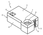
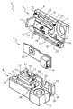
図1および図2は、本発明の1実施形態である流速測定装置1のそれぞれ前面および背面を上にした様子を示す。図1において、流速測定装置1は、上方から下方に流れる被測定流体の中に設置される。流速測定装置1は、略直方体の本体2を有し、本体2は、被測定流体の上流側の前側半体3と、下流側の後側半体4とに2分割され、本体2内部に基板5が挟み込まれている。流速測定装置1の本体2の長手方向の一端には、前側半体3の前面に開口する導入口6が設けられ、本体2の他端には、前側半体3および後側半体4を貫通し、両面に座ぐり7を有する取付穴8が設けられている。また、流速測定装置1の本体2の取付穴8が設けられた側の端面には、基板5上に設けられたコネクタ9が露出している。さらに、導入口6が設けられた側の本体2の端部の背面には後側半体4に設けた排出口10が開口しており、排出口10は、本体2の側面部分が前側半体3に突設した壁部11で封止されている。
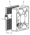
図11は、流速測定装置1の使用例を示す。流速測定装置1は、電化製品などの内部を冷却するための空気の流量を測定するためなどに用いられ、空気取り入れ口のフィルタ41とフィルタ41を通して外気を吸入する吸気ファン42との間に、導入口6をフィルタ41に正対し、排出口10を吸気ファン42に正対して空気の流れの端に設置される。通常、フィルタ41と冷却ファン42との間の距離Lは短い方が電化製品を小型化する上で好ましい。また。図12に、流速測定装置1の配置を空気の流れ方向の下流側から見た様子を示す。流速測定装置1は、排出口10が設けられた端部だけが空気の流れの中に突出するように固定され、図中に斜線で示した部分の面積Sが、実質的に空気の流れを遮断する面積である。
2 本体
3 前側半体
4 後側半体
5 基板
6 導入口
10 排出口
11 壁部
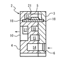
12 流路
13 収納部
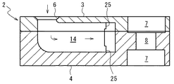
14 導入流路
15 分岐流路
16 測定流路
17 センサ開口
22 センサ素子
27 横穴(排出流路)
Claims (10)
- 本体の表面に設けられ、被測定流体の上流に向かって開口する導入口と、
前記本体の内部に、前記導入口から直線的に延伸してから円弧状に彎曲した導入流路と、
前記導入流路の前記円弧状に彎曲した部分から前記彎曲の内側方向に分岐して前記導入流路の前記直線的に延伸する部分と平行に延伸し、末端が前記本体の表面に開口する第1排出口に接続された分岐流路と、
前記導入流路の末端と連通し、前記導入流路の前記直線的に延伸する部分と平行に延伸して末端が前記本体の表面に開口する第2排出口に接続された排出流路と、
前記分岐流路からさらに分岐して末端が前記本体の表面に開口する第3排出口に接続され、その中にセンサ素子が設けられた測定流路とを有し、
前記測定流路は、前記導入流路から前記分岐流路への分岐点における前記導入流路の流路方向および前記分岐流路の流路方向に対して直角な方向に、前記排出流路と重なり合う部分を有することを特徴とする流速測定装置。 - 前記導入流路から前記分岐路への分岐点における前記分岐流路の流路方向は、前記導入口の対向する方向と直角な方向であることを特徴とする請求項1に記載の流速測定装置。
- 前記本体は、接合面で互いに接合される2つの半体からなり、
前記排出流路は、前記半体の接合面に設けた溝に連通し、前記半体の側面の開口部から前記半体の接合面に平行に延伸し、少なくとも一部分が前記接合面に開放せず、奥部で前記溝と連通する横穴からなることを特徴とする請求項1または2に記載の流速測定装置。 - 前記導入流路、前記分岐流路および前記測定流路は、前記半体の接合面に設けた溝からなることを特徴とする請求項3に記載の流速測定装置。
- 前記横穴は、前記半体の側面の開口部において、前記接合面と反対側の表面にも開口し、該開口部の側面側がもう一方の半体に設けた壁部で封止されたことを特徴とする請求項3または4に記載の流速測定装置。
- 前記半体の接合面にさらに設けた溝によって、前記測定流路に隣接し、前記測定流路に開口するセンサ開口を有する収納部が画定され、
前記センサ素子は、前記収納部内に前記半体の接合方向に端面を向けて収納された基板上に設けられ、前記センサ開口から前記測定流路の内側に露出することを特徴とする請求項3から5のいずれかに記載の流速測定装置。 - 前記半体の接合面に設けた溝は、前記2つの半体の両接合面に設けた深さが不連続に変化する溝であることを特徴とする請求項6に記載の流速測定装置。
- 前記半体の接合面に設けた溝は、前記導入流路を画定する部分より前記分岐流路を画定する部分が浅く、前記分岐流路を画定する部分より前記測定流路を画定する部分が浅くなっていることを特徴とする請求項7に記載の流速測定装置。
- 前記導入口、前記第1排出口、第2排出口および第3排出口は、すべて前記本体の1つの端部付近に開口することを特徴とする請求項1から8のいずれかに記載の流速測定装置。
- 前記第1排出口、第2排出口および第3排出口は、前記本体の背面に開口する1つの排出口からなることを特徴とする請求項9に記載の流速測定装置。
Priority Applications (5)
| Application Number | Priority Date | Filing Date | Title |
|---|---|---|---|
| JP2004346724A JP4120637B2 (ja) | 2004-11-30 | 2004-11-30 | 流速測定装置 |
| EP05024582.8A EP1691175B1 (en) | 2004-11-30 | 2005-11-10 | Flow-velocity measuring device |
| CNB200510126929XA CN100425992C (zh) | 2004-11-30 | 2005-11-28 | 流速测量装置 |
| KR1020050114649A KR100724243B1 (ko) | 2004-11-30 | 2005-11-29 | 유속 측정 장치 |
| US11/291,699 US7284423B2 (en) | 2004-11-30 | 2005-11-30 | Flow-velocity measuring device |
Applications Claiming Priority (1)
| Application Number | Priority Date | Filing Date | Title |
|---|---|---|---|
| JP2004346724A JP4120637B2 (ja) | 2004-11-30 | 2004-11-30 | 流速測定装置 |
Publications (3)
| Publication Number | Publication Date |
|---|---|
| JP2006153734A JP2006153734A (ja) | 2006-06-15 |
| JP2006153734A5 JP2006153734A5 (ja) | 2008-01-17 |
| JP4120637B2 true JP4120637B2 (ja) | 2008-07-16 |
Family
ID=36035758
Family Applications (1)
| Application Number | Title | Priority Date | Filing Date |
|---|---|---|---|
| JP2004346724A Expired - Lifetime JP4120637B2 (ja) | 2004-11-30 | 2004-11-30 | 流速測定装置 |
Country Status (5)
| Country | Link |
|---|---|
| US (1) | US7284423B2 (ja) |
| EP (1) | EP1691175B1 (ja) |
| JP (1) | JP4120637B2 (ja) |
| KR (1) | KR100724243B1 (ja) |
| CN (1) | CN100425992C (ja) |
Families Citing this family (22)
| Publication number | Priority date | Publication date | Assignee | Title |
|---|---|---|---|---|
| CN101641576B (zh) * | 2007-02-28 | 2011-11-09 | 株式会社山武 | 流量传感器 |
| JP5134865B2 (ja) * | 2007-05-30 | 2013-01-30 | 三洋電機株式会社 | 冷却風量検出装置及びそれを用いた投写型映像表示装置 |
| JP5363332B2 (ja) * | 2007-10-31 | 2013-12-11 | 一般財団法人生産技術研究奨励会 | 成形用材料の流動速度計測方法及び流動速度測定装置 |
| JP5061963B2 (ja) * | 2008-03-05 | 2012-10-31 | オムロン株式会社 | 流量センサ |
| JP4910179B2 (ja) * | 2008-05-28 | 2012-04-04 | Smc株式会社 | フローセンサ |
| US8695690B2 (en) * | 2008-08-29 | 2014-04-15 | Apple Inc. | Methods for cooling electronic devices using flow sensors |
| US7891238B2 (en) | 2008-12-23 | 2011-02-22 | Honeywell International Inc. | Thermal anemometer flow sensor apparatus with a seal with conductive interconnect |
| US8113046B2 (en) | 2010-03-22 | 2012-02-14 | Honeywell International Inc. | Sensor assembly with hydrophobic filter |
| US8397586B2 (en) | 2010-03-22 | 2013-03-19 | Honeywell International Inc. | Flow sensor assembly with porous insert |
| US8656772B2 (en) | 2010-03-22 | 2014-02-25 | Honeywell International Inc. | Flow sensor with pressure output signal |
| US8756990B2 (en) | 2010-04-09 | 2014-06-24 | Honeywell International Inc. | Molded flow restrictor |
| US8418549B2 (en) * | 2011-01-31 | 2013-04-16 | Honeywell International Inc. | Flow sensor assembly with integral bypass channel |
| US9003877B2 (en) | 2010-06-15 | 2015-04-14 | Honeywell International Inc. | Flow sensor assembly |
| JP5364059B2 (ja) * | 2010-08-30 | 2013-12-11 | Ckd株式会社 | 熱式流量計 |
| US8695417B2 (en) | 2011-01-31 | 2014-04-15 | Honeywell International Inc. | Flow sensor with enhanced flow range capability |
| DE102011005768A1 (de) * | 2011-03-18 | 2012-09-20 | Robert Bosch Gmbh | Vorrichtung zur Erfassung mindestens einer Eigenschaft eines fluiden Mediums |
| EP2624542B1 (en) * | 2012-01-31 | 2017-03-29 | Samsung Electronics Co., Ltd. | Television |
| JP5949472B2 (ja) * | 2012-11-09 | 2016-07-06 | 株式会社デンソー | 空気流量測定装置 |
| US9052217B2 (en) | 2012-11-09 | 2015-06-09 | Honeywell International Inc. | Variable scale sensor |
| US9952079B2 (en) | 2015-07-15 | 2018-04-24 | Honeywell International Inc. | Flow sensor |
| US20190293467A1 (en) * | 2018-03-20 | 2019-09-26 | Honeywell International Inc. | Mass air flow sensor with absolute pressure compensation |
| US20240390568A1 (en) * | 2023-05-25 | 2024-11-28 | Honeywell International Inc. | Devices for delivering at least one flowing media, associated sensor modules, and associated methods of mechanically and electrically coupling a sensor module to a device for delivering at least one flowing media |
Family Cites Families (8)
| Publication number | Priority date | Publication date | Assignee | Title |
|---|---|---|---|---|
| US4215565A (en) * | 1977-09-01 | 1980-08-05 | Agar Instrumentation Inc. | Method and apparatus for testing a fluid |
| DE3124960A1 (de) * | 1981-06-25 | 1983-01-20 | Robert Bosch Gmbh, 7000 Stuttgart | "vorrichtung zur messung der masse eines stroemenden mediums" |
| US4914947A (en) | 1988-09-30 | 1990-04-10 | Honeywell Inc. | Sampling probe flow sensor |
| JPH03124457A (ja) * | 1989-10-09 | 1991-05-28 | Casio Comput Co Ltd | 印字ヘッドの製造方法 |
| JP3124457B2 (ja) | 1995-02-03 | 2001-01-15 | 株式会社山武 | 流量計 |
| WO2000077478A1 (fr) * | 1999-06-14 | 2000-12-21 | Yamatake Corporation | Detecteur de vitesse d'ecoulement |
| KR20010039993A (ko) * | 1999-10-06 | 2001-05-15 | 오카무라 가네오 | 유량 및 유속 측정장치 |
| JP4534526B2 (ja) * | 2004-02-27 | 2010-09-01 | オムロン株式会社 | 流速測定装置 |
-
2004
- 2004-11-30 JP JP2004346724A patent/JP4120637B2/ja not_active Expired - Lifetime
-
2005
- 2005-11-10 EP EP05024582.8A patent/EP1691175B1/en not_active Expired - Lifetime
- 2005-11-28 CN CNB200510126929XA patent/CN100425992C/zh not_active Expired - Lifetime
- 2005-11-29 KR KR1020050114649A patent/KR100724243B1/ko not_active Expired - Lifetime
- 2005-11-30 US US11/291,699 patent/US7284423B2/en active Active
Also Published As
| Publication number | Publication date |
|---|---|
| EP1691175A1 (en) | 2006-08-16 |
| US7284423B2 (en) | 2007-10-23 |
| KR100724243B1 (ko) | 2007-05-31 |
| CN1782712A (zh) | 2006-06-07 |
| JP2006153734A (ja) | 2006-06-15 |
| EP1691175B1 (en) | 2020-08-05 |
| CN100425992C (zh) | 2008-10-15 |
| KR20060060597A (ko) | 2006-06-05 |
| US20060137444A1 (en) | 2006-06-29 |
Similar Documents
| Publication | Publication Date | Title |
|---|---|---|
| JP4120637B2 (ja) | 流速測定装置 | |
| KR101029168B1 (ko) | 라인 내부를 유동하는 공기의 매스를 측정하는 장치 | |
| CN102636227B (zh) | 传感器的结构 | |
| US7305877B2 (en) | Device for determining at least one parameter of a medium flowing in a line having diversion surface | |
| JP6237495B2 (ja) | 空気流量測定装置 | |
| JP6194852B2 (ja) | 湿度検出機能付き空気流量測定装置 | |
| KR20140009161A (ko) | 유체의 유동 특성을 검출하기 위한 센서 장치 | |
| CN102538867A (zh) | 传感器的结构 | |
| CN100381824C (zh) | 流速测定装置 | |
| CN100533069C (zh) | 流速测量装置 | |
| CN106662476A (zh) | 物理量检测装置 | |
| KR20170047263A (ko) | 측정 채널을 관류하는 유체 매체의 적어도 하나의 매개변수를 측정하기 위한 센서 장치 | |
| JP2006153734A5 (ja) | ||
| CN106949940B (zh) | 用于感测流动的流体介质至少一个流动特性的传感器装置 | |
| JP5971221B2 (ja) | 空気流量測定装置 | |
| KR20160122153A (ko) | 채널을 통해 유동하는 유체 매체의 적어도 하나의 파라미터를 결정하기 위한 센서 장치 | |
| CN107532935A (zh) | 用于确定流经测量通道的流体介质的至少一个参数的传感器 | |
| CN100405035C (zh) | 压力传感装置 | |
| JP6734939B2 (ja) | 熱式流量計 | |
| KR20080015926A (ko) | 유량 센서 | |
| JP2009132085A5 (ja) | ||
| JP6690899B2 (ja) | 空気流量測定装置 | |
| US9689358B2 (en) | Air flow measuring device | |
| JP2000002573A (ja) | 気体流量計測装置 | |
| JPH11271107A (ja) | 圧力取出構造 |
Legal Events
| Date | Code | Title | Description |
|---|---|---|---|
| A521 | Request for written amendment filed |
Free format text: JAPANESE INTERMEDIATE CODE: A523 Effective date: 20071128 |
|
| A621 | Written request for application examination |
Free format text: JAPANESE INTERMEDIATE CODE: A621 Effective date: 20071128 |
|
| A871 | Explanation of circumstances concerning accelerated examination |
Free format text: JAPANESE INTERMEDIATE CODE: A871 Effective date: 20071128 |
|
| A975 | Report on accelerated examination |
Free format text: JAPANESE INTERMEDIATE CODE: A971005 Effective date: 20071225 |
|
| A131 | Notification of reasons for refusal |
Free format text: JAPANESE INTERMEDIATE CODE: A131 Effective date: 20080108 |
|
| A521 | Request for written amendment filed |
Free format text: JAPANESE INTERMEDIATE CODE: A523 Effective date: 20080304 |
|
| TRDD | Decision of grant or rejection written | ||
| A01 | Written decision to grant a patent or to grant a registration (utility model) |
Free format text: JAPANESE INTERMEDIATE CODE: A01 Effective date: 20080401 |
|
| A61 | First payment of annual fees (during grant procedure) |
Free format text: JAPANESE INTERMEDIATE CODE: A61 Effective date: 20080414 |
|
| FPAY | Renewal fee payment (event date is renewal date of database) |
Free format text: PAYMENT UNTIL: 20110509 Year of fee payment: 3 |
|
| R150 | Certificate of patent or registration of utility model |
Ref document number: 4120637 Country of ref document: JP Free format text: JAPANESE INTERMEDIATE CODE: R150 Free format text: JAPANESE INTERMEDIATE CODE: R150 |
|
| FPAY | Renewal fee payment (event date is renewal date of database) |
Free format text: PAYMENT UNTIL: 20120509 Year of fee payment: 4 |
|
| FPAY | Renewal fee payment (event date is renewal date of database) |
Free format text: PAYMENT UNTIL: 20130509 Year of fee payment: 5 |
|
| FPAY | Renewal fee payment (event date is renewal date of database) |
Free format text: PAYMENT UNTIL: 20140509 Year of fee payment: 6 |
|
| R250 | Receipt of annual fees |
Free format text: JAPANESE INTERMEDIATE CODE: R250 |
|
| EXPY | Cancellation because of completion of term |