JP4098231B2 - Socket for semiconductor device - Google Patents
Socket for semiconductor device Download PDFInfo
- Publication number
- JP4098231B2 JP4098231B2 JP2003423833A JP2003423833A JP4098231B2 JP 4098231 B2 JP4098231 B2 JP 4098231B2 JP 2003423833 A JP2003423833 A JP 2003423833A JP 2003423833 A JP2003423833 A JP 2003423833A JP 4098231 B2 JP4098231 B2 JP 4098231B2
- Authority
- JP
- Japan
- Prior art keywords
- guide member
- movement amount
- contact
- semiconductor device
- movable contact
- Prior art date
- Legal status (The legal status is an assumption and is not a legal conclusion. Google has not performed a legal analysis and makes no representation as to the accuracy of the status listed.)
- Expired - Lifetime
Links
- 239000004065 semiconductor Substances 0.000 title claims description 132
- 230000002093 peripheral effect Effects 0.000 claims description 41
- 230000001105 regulatory effect Effects 0.000 claims description 11
- 238000000926 separation method Methods 0.000 claims description 5
- 238000005192 partition Methods 0.000 description 8
- 238000012360 testing method Methods 0.000 description 7
- 230000000694 effects Effects 0.000 description 3
- 239000004020 conductor Substances 0.000 description 2
- 230000002452 interceptive effect Effects 0.000 description 2
- 230000005856 abnormality Effects 0.000 description 1
- 230000007547 defect Effects 0.000 description 1
- 238000001514 detection method Methods 0.000 description 1
- 238000009434 installation Methods 0.000 description 1
Images


Classifications
-
- H—ELECTRICITY
- H05—ELECTRIC TECHNIQUES NOT OTHERWISE PROVIDED FOR
- H05K—PRINTED CIRCUITS; CASINGS OR CONSTRUCTIONAL DETAILS OF ELECTRIC APPARATUS; MANUFACTURE OF ASSEMBLAGES OF ELECTRICAL COMPONENTS
- H05K7/00—Constructional details common to different types of electric apparatus
- H05K7/02—Arrangements of circuit components or wiring on supporting structure
- H05K7/10—Plug-in assemblages of components, e.g. IC sockets
- H05K7/1053—Plug-in assemblages of components, e.g. IC sockets having interior leads
- H05K7/1076—Plug-in assemblages of components, e.g. IC sockets having interior leads co-operating by sliding
- H05K7/1084—Plug-in assemblages of components, e.g. IC sockets having interior leads co-operating by sliding pin grid array package carriers
Landscapes
- Engineering & Computer Science (AREA)
- Microelectronics & Electronic Packaging (AREA)
- Connecting Device With Holders (AREA)
- Testing Of Individual Semiconductor Devices (AREA)
Description
本発明は、半導体装置の試験に用いられる半導体装置用ソケットに関する。 The present invention relates to a semiconductor device socket used for testing a semiconductor device.
電子機器などに実装される半導体装置は、実装される以前の段階で種々の試験が行われその潜在的欠陥が除去される。その試験は、熱的および機械的環境試験などに対応した電圧ストレス印加、高温動作、高温保存などにより非破壊的に実施される。 A semiconductor device mounted on an electronic device or the like is subjected to various tests at a stage before mounting to remove potential defects. The test is performed non-destructively by voltage stress application, high temperature operation, high temperature storage, etc. corresponding to thermal and mechanical environment tests.
このような試験に供される半導体装置用ソケットは、一般に、ICソケットと称され、例えば、特許文献2および図7にも示されるように、所定の試験電圧が供給されるとともに被検査物としての半導体装置からの短絡等をあらわす異常検出信号を送出する入出力部を有するプリント配線基板2上に配される。 A socket for a semiconductor device used for such a test is generally called an IC socket. For example, as shown in Patent Document 2 and FIG. 7, a predetermined test voltage is supplied and an object to be inspected is used. 1 is disposed on a printed wiring board 2 having an input / output unit for transmitting an abnormality detection signal representing a short circuit from the semiconductor device.
半導体装置用ソケットは、プリント配線基板2上に固定され後述するコンタクト移動用部材8を、コンタクト端子16ai(i=1〜n,nは正の整数)の一対の可動接点部に対し相対的に移動可能に収容する収容部4aを有するソケット本体4と、半導体装置として、例えば、BGA型(Ball Grid Array)の半導体素子6(図8(A)参照)が装着される収容部10aを有し、半導体素子6を収容部10aに案内するとともに半導体素子6のコンタクト端子16aiに対する相対位置を位置決めする案内部材10と、所定の方向に沿って往復動可能にソケット本体4内に配され、後述するコンタクト端子16aiの一方の可動接点部16Mを他方の可動接点部16Fに対し近接または離隔させるコンタクト移動用部材8と、作用される操作力を図示が省略されるコンタクト移動用部材8の駆動機構を介して駆動力としてコンタクト移動用部材8に伝達するカバー部材12とを含んで構成されている。
The socket for a semiconductor device is fixed on the printed wiring board 2 and a
プリント配線基板2における所定位置には、その入出力部に導体層を通じて電気的に接続される電極群が形成されている。その電極群には、図7に示されるように、プリント配線基板2上に配されるソケット本体4に設けられる複数のコンタクト端子16aiの基端側の端子16Bが接続されている。
An electrode group that is electrically connected to the input / output portion through a conductor layer is formed at a predetermined position on the printed wiring board 2. As shown in FIG. 7, the electrode group is connected to
ソケット本体4は、複数のコンタクト端子16aiの可動接点部16Mおよび16Fが突出する収容部4aを内側に有している。
The socket body 4 has an
各コンタクト端子16aiは、装着される半導体素子6の各電極部6aに対応してソケット本体4に設けられる基端側の端子16Bと、その端子16Bに結合され半導体素子6の各電極部6aを選択的に挟持する一対の可動接点部16Fおよび16Mと、からなる。一対の可動接点部16Fおよび16Mは、図8(A)および(C)に示されるように、コンタクト移動用部材8の移動に応じて互いに近接し半導体素子6の各電極部6aを挟持し、または、互いに離隔し半導体素子6の各電極部6aを解放状態とするものとされる。
Each contact terminal 16ai is connected to a
案内部材10の底部を相対的に移動させることなく一体に上部に固着するコンタクト移動用部材8は、ソケット本体4の収容部4aに、各コンタクト端子16aiの可動接点部16Mおよび16Fの運動方向に沿って移動可能に配されている。
The
コンタクト移動用部材8は、各コンタクト端子16aiの可動接点部16Mおよび16Fが突出する開口部を内部に有している。各開口部は、それぞれ、図示が省略される隔壁により仕切られている。
The
コンタクト移動用部材8における各コンタクト端子16aiの可動接点部16Mおよび16Fが突出する隣接する各開口部相互間には、可動接点部16Mと可動接点部16Fとを仕切るように形成される可動接点押圧部8Pがそれぞれ設けられている。さらに、コンタクト移動用部材8の一端とソケット本体4の収容部4aの内周部との間には、図示が省略されるが、コンタクト移動用部材8を図7、および、図8(C)に示される初期位置に戻すべく付勢する付勢部材が設けられている。初期位置においては、コンタクト移動用部材8の一方の端面とソケット本体4の収容部4aの内周面とが隙間なく当接するものとされる。
Movable contact press formed so as to partition the
さらに、コンタクト移動用部材8は、特許文献2にも示されるような、レバーおよびピンからなる駆動機構に連結されている。その駆動機構のレバーの一端は、カバー部材12の端部に当接している。
Further, the
これにより、図8(A)に示される矢印Dの示す方向に沿った、カバー部材12の下降動作に応じてコンタクト移動用部材8が図8(A)に示される矢印Mの示す方向に、付勢手段の付勢力に抗して移動せしめられるとき、可動接点押圧部8Pが各コンタクト端子16aiの可動接点部16Mを可動接点部16Fに対して離隔させるように移動せしめられる。一方、図8(B)に示されるように、カバー部材12の上昇動作に応じて図8(A)の矢印Mの示す方向とは反対方向に、コンタクト移動用部材8が付勢手段の付勢力および可動接点部16Mの復元力により移動せしめられる。
Thereby, the
案内部材10は、図7に示されるように、その中央部に、半導体素子6が着脱可能に装着される収容部10aを有している。収容部10aの内周面は、正方形の半導体素子6の各端面がそれぞれ対向する平坦面と、上端面とその平坦面とを結合する斜面部と、平坦面に交叉する底面部とにより形成されている。収容部10aの内周面の寸法は、所定の公差をもって装着される半導体素子6の外形寸法よりも大に設定されている。即ち、図8(A)および(C)に示されるように、コンタクト移動用部材8が最大に移動したとき、半導体素子6の各端面と案内部材10の平坦面との間の隙間Cの値は、図7に示される位置から図8(A)に示される位置までの可動接点押圧部8Pの最大移動量A(コンタクト移動用部材8の移動量)と追従する半導体素子6の各電極6aの最大移動量B(半導体素子6の移動量)との差(A−B)よりも小に設定されている(C<A−B)。なお、最大移動量Bの値は、最大移動量Aの値よりも小なる値とされる。
As shown in FIG. 7, the
カバー部材12は、案内部材10の外周を包囲するように開口12aを内側に有している。カバー部材12は、ソケット本体4に対し昇降動可能にソケット本体4に支持されている。
The
かかる構成において、図示が省略される搬送ロボットのハンドに保持される半導体素子6が、開口12aを通じて案内部材10の収容部10a内に装着されるとき、先ず、カバー部材12が搬送ロボットの押圧部により図8(A)に示される最下端位置まで下降せしめられるとともに半導体素子6が下降せしめられる。
これにより、図8(A)に示されるように、コンタクト移動用部材8が付勢手段の付勢力に抗して移動せしめられる。
In such a configuration, when the
Thereby, as shown in FIG. 8A, the
次に、図9(A)に拡大されて示されるように、可動接点押圧部8Pが各コンタクト端子16aiの可動接点部16Mを可動接点部16Fに対して離隔させるように移動せしめられ保持される状態において、半導体素子6が案内部材10の収容部10aに載置されることにより、半導体素子6の電極部6aが各コンタクト端子16aiの可動接点部16Mと可動接点部16Fとの間に対し位置決めされる。
Next, as shown in an enlarged view in FIG. 9A, the movable
そして、半導体素子6の各電極6aが各コンタクト端子16aiの可動接点部16Mおよび16Fの相互間に配された状態で、図8(B)に示されるように、カバー部材12が上昇せしめられるとき、コンタクト移動用部材8が付勢手段の付勢力および可動接点部16Mの復元力により初期の位置まで移動せしめられることにより、可動接点押圧部8Pが可動接点部16Mから離隔し可動接点部16Fに対して接触することとなる。
Then, when the
従って、図8(B)および図9(B)に示されるように、半導体素子6の各電極部6aが各コンタクト端子16aiの可動接点部16Mおよび可動接点部16Fにより挟持されることにより、半導体素子6の各電極部6aが各コンタクト端子16aiに電気的に接続状態となる。
Therefore, as shown in FIG. 8B and FIG. 9B, each
このような半導体装置用ソケットにおいて、図8(B)に示されるように、カバー部材12が上昇せしめられ、コンタクト移動用部材8が付勢手段の付勢力および可動接点部16Mの復元力により初期の位置まで移動せしめられるとき、半導体素子6の端面が上述の案内部材10の収容部10aの平坦面と干渉する場合がある。即ち、上述したように、隙間Cの値が、図7に示される位置から図8(A)に示される位置までの可動接点押圧部8Pの最大移動量A(コンタクト移動用部材8の移動量)と追従する半導体素子6の各電極6aの最大移動量B(半導体素子6の移動量)との差(A−B)よりも小に設定されているので干渉量D(=A−B−C)が零近傍とはならず、しかも、最大移動量Aと最大移動量Bとの差の値は、半導体素子6の各電極6aの大きさに応じて大となる場合もあるので零を超える正の値となる場合があるからである。これは、位置決め精度の要求から隙間Cの値を比較的大に設定することにも限界があることも一因となっている。
In such a semiconductor device socket, as shown in FIG. 8B, the
また、図8(C)に示されるように、収容部10aの平坦面と干渉した半導体素子6がさらに案内部材10の移動に伴い押圧されることにより、図8(D)に拡大して示されるように、半導体素子6の電極6aが可動接点部16Mに対し離隔する、所謂、片当たりとなる虞がある。
Further, as shown in FIG. 8C, the
このような場合、コンタクト移動用部材8が最大に移動したとき、半導体素子6の各端面と案内部材10の平坦面との間の隙間Cの値が適正に設定されているが、その代わりに、半導体素子6が装着された後、コンタクト移動用部材8が、元の位置に戻されたとき、
半導体素子6の各端面と案内部材10の平坦面との間の隙間Cの値が適正に設定されるように構成される場合においては、コンタクト移動用部材8が最大に移動したとき、案内部材10の中心位置が、コンタクト端子16ai群の略中心位置からずれるので可動接点部16Mと可動接点16Fとの間に半導体素子6の電極6aの中心位置が対応しないこととなり、従って、半導体素子6の装着が困難となる虞がある。
In such a case, when the
In the case where the value of the gap C between each end face of the
そこで、特許文献1にも示されるように、案内部材がコンタクト移動用部材に対して相対的に移動可能にコンタクト移動用部材上に支持されるもとで、案内部材の移動量が所定の範囲内に規制されるものが提案されている。 Therefore, as shown in Patent Document 1, the amount of movement of the guide member is within a predetermined range while the guide member is supported on the contact movement member so as to be movable relative to the contact movement member. Something that is regulated within is proposed.
特許文献1にも開示されるような、案内部材がコンタクト移動用部材に対して相対的に所定の範囲だけ移動可能とされる装置は、各コンタクト端子16aiの可動接点部16Mの復元変位を容易に行なわせる点に関し有効である。
As disclosed in Patent Document 1, the device in which the guide member is movable relative to the contact moving member by a predetermined range can easily restore the
しかしながら、案内部材がコンタクト移動用部材に対して相対的に所定の範囲だけ移動可能な構成だけでは、上述のような半導体素子6の端面が上述の案内部材10の収容部10aの平坦面と干渉する事態を確実に回避することはできない場合がある。
However, the end face of the
以上の問題点を考慮し、本発明は、半導体装置の試験に用いられる半導体装置用ソケットであって、装着される半導体素子の端面が案内部材の収容部を形成する内周面と干渉する事態を確実に回避することができる半導体装置用ソケットを提供することを目的とする。 In view of the above problems, the present invention is a socket for a semiconductor device used for testing a semiconductor device, and the situation where the end face of the semiconductor element to be mounted interferes with the inner peripheral surface forming the accommodating portion of the guide member An object of the present invention is to provide a socket for a semiconductor device that can reliably avoid the above.
上述の目的を達成するために、本発明に係る半導体装置用ソケットは、半導体装置の端子を、互いに近接して挟持し電気的に接続するとともに、互いに離隔し解放する一対の可動接点を有するコンタクト端子の基端部を支持するソケット本体と、ソケット本体内に一対の可動接点における近接または離隔方向に沿って移動可能に配されコンタクト端子の一対の可動接点を半導体装置の端子に近接または離隔させる押圧部を有する可動接点移動用部材と、可動接点移動用部材の収容部に配され、半導体装置を案内するとともに半導体装置の端子を一対の可動接点に対し位置決めすることにより、半導体装置の端面との相互間に所定の隙間を形成する案内部材と、一対の可動接点における近接または離隔方向に沿った案内部材の最大移動量を規制する移動量規制部と、を備え、所定の隙間が、案内部材の最大移動量と半導体装置の最大移動量との差に応じて設定されるとともに、移動量規制部が一対の可動接点における近接または離隔方向に沿った案内部材の最大移動量を規制するとき、半導体装置の最大移動量に対応した隙間が、案内部材の端面と移動量規制部との間に設定され、移動量規制部が、案内部材の最大移動量を半導体装置の最大移動量に規制することを特徴とする。 In order to achieve the above object, a socket for a semiconductor device according to the present invention is a contact having a pair of movable contacts for holding and electrically connecting terminals of a semiconductor device close to each other and separating and releasing them from each other. A socket body that supports a base end portion of the terminal, and a pair of movable contacts that are movably disposed in the socket body along a proximity or separation direction of the pair of movable contacts, so that the pair of movable contacts of the contact terminals are close to or separated from the terminals of the semiconductor device. A movable contact moving member having a pressing portion, and an end face of the semiconductor device disposed in the accommodating portion of the movable contact moving member for guiding the semiconductor device and positioning the terminals of the semiconductor device with respect to the pair of movable contacts, a guide member for forming a predetermined gap between each other, restricting the maximum amount of movement of the guide member along the proximity or spacing direction of the pair of movable contacts Includes a movement amount regulating unit that, a predetermined gap, while being set in accordance with the difference between the maximum moving amount and the maximum amount of movement of the semiconductor device of the guide member, approach movement amount restricting portion of the pair of movable contacts Alternatively, when restricting the maximum movement amount of the guide member along the separation direction, a gap corresponding to the maximum movement amount of the semiconductor device is set between the end surface of the guide member and the movement amount restriction portion, and the movement amount restriction portion is The maximum movement amount of the guide member is limited to the maximum movement amount of the semiconductor device.
以上の説明から明らかなように、本発明に係る半導体装置用ソケットによれば、所定の隙間が、案内部材の最大移動量と半導体装置の最大移動量との差に応じて設定され、移動量規制部が、案内部材の最大移動量を半導体装置の最大移動量に規制することにより、案内部材の最大移動量と半導体装置の最大移動量との差が変化しない一定の値となるのでその隙間が確保される結果として、装着される半導体素子の端面が案内部材の収容部を形成する内周面と干渉する事態を確実に回避することができる。 As is clear from the above description, according to the socket for a semiconductor device according to the present invention, the predetermined gap is set according to the difference between the maximum movement amount of the guide member and the maximum movement amount of the semiconductor device, and the movement amount Since the restricting unit restricts the maximum movement amount of the guide member to the maximum movement amount of the semiconductor device, the difference between the maximum movement amount of the guide member and the maximum movement amount of the semiconductor device becomes a constant value that does not change. As a result, it is possible to reliably avoid the situation where the end surface of the semiconductor element to be mounted interferes with the inner peripheral surface forming the accommodating portion of the guide member.
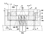
図2は、本発明に係る半導体装置用ソケットの第1実施例の全体構成を概略的に示す。
図2は、後述する半導体素子が未だ装着されていない状態を示す。
図2において、半導体装置用ソケットは、プリント配線基板22上に固定され後述するコンタクト移動用部材28を、コンタクト端子26ai(i=1〜n,nは正の整数)の一対の可動接点部に対し相対的に移動可能に収容する収容部24aを有するソケット本体24と、半導体装置として、例えば、BGA型(Ball Grid Array)の半導体素子36(図3参照)が装着される収容部20aを有し、半導体素子36を収容部20a内に案内するとともに半導体素子36のコンタクト端子26aiに対する相対位置を位置決めする案内部材20と、所定の方向に沿って往復動可能にソケット本体24内に配され、後述するコンタクト端子26aiの一方の可動接点部26Mを他方の可動接点部26Fに対し近接または離隔させるコンタクト移動用部材28と、作用される操作力を図示が省略されるコンタクト移動用部材28の駆動機構を介して駆動力としてコンタクト移動用部材28に伝達するカバー部材32とを含んで構成されている。
FIG. 2 schematically shows the overall configuration of the first embodiment of the socket for a semiconductor device according to the present invention.
FIG. 2 shows a state where a semiconductor element to be described later is not yet mounted.
In FIG. 2, the semiconductor device socket is fixed on the printed
プリント配線基板22における所定位置には、その入出力部に導体層を通じて電気的に接続される電極群が形成されている。その電極群には、図2に示されるように、プリント配線基板22上に配されるソケット本体24に設けられる複数のコンタクト端子26aiの基端側の端子26Bが接続されている。
An electrode group that is electrically connected to the input / output portion through a conductor layer is formed at a predetermined position on the printed
ソケット本体24は、複数のコンタクト端子26aiの可動接点部26Mおよび26Fが突出する収容部24aを内側に有している。また、ソケット本体24は、各コンタクト端子26aiの基端部が圧入される支持孔24bを有している。各支持孔24bの一方の開口端は、収容部24a内に開口している。
The
また、ソケット本体24における収容部24aの周縁の4箇所には、後述する案内部材20の最大移動量を規制する移動量規制部としてのポスト部24Pが一体に設けられている。
Further,
各コンタクト端子26aiは、装着される半導体素子36の各電極部36aに対応してソケット本体24に設けられる基端側の端子26Bと、その端子26Bに結合され半導体素子36の各電極部36aを選択的に挟持する一対の可動接点部26Fおよび26Mと、からなる。一対の可動接点部26Fおよび26Mは、図1および図3に示されるように、コンタクト移動用部材28の移動に応じて互いに近接し半導体素子36の各電極部36aを挟持し、または、互いに離隔し半導体素子36の各電極部36aを解放状態とするものとされる。
Each contact terminal 26ai includes a
案内部材20の底部を相対的に移動し得るように支持するコンタクト移動用部材28は、ソケット本体24の収容部24aに、各コンタクト端子26aiの可動接点部26Mおよび26Fの運動方向に沿って移動可能に配されている。
可動接点移動用部材としてのコンタクト移動用部材28は、各コンタクト端子26aiの可動接点部26Mおよび26Fが突出する開口部28bを内部に有している。各開口部28bは、それぞれ、図示が省略される隔壁により仕切られている。その隔壁は、紙面に略垂直方向に所定の間隔で各コンタクト端子26aiに対応して形成されている。
The
The
コンタクト移動用部材28において、各列ごとの各開口部28bには、開口部28bを複数に分割し、かつ、可動接点部26Mと可動接点部26Fとを仕切るように形成される可動接点押圧部28Pが複数個、設けられている。さらに、コンタクト移動用部材28の一端とソケット本体24の収容部24aの内周部との間には、図示が省略されるが、コンタクト移動用部材28を図1に示される位置から図3に示される位置までに戻すべく付勢する付勢部材が設けられている。
初期位置においては、図2に示されるように、コンタクト移動用部材28における移動方向に対し略直交する一方の端面とソケット本体24の収容部24aの内周面とが隙間なく当接するものとされる。
In the
In the initial position, as shown in FIG. 2, one end surface of the
さらに、コンタクト移動用部材28は、特許文献2にも示されるような、レバーおよびピンからなる駆動機構に連結されている。その備えられる駆動機構のレバーの一端は、カバー部材32の端部に当接している。
Further, the
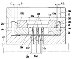
これにより、図1に示される矢印Dの示す方向に沿った、カバー部材32の下降動作に応じてコンタクト移動用部材28が図1に示される矢印Mの示す方向に、付勢手段の付勢力に抗して移動せしめられるとき、可動接点押圧部28Pが各コンタクト端子26aiの可動接点部26Mを可動接点部26Fに対して離隔させるように移動せしめられる。一方、図3に示されるように、カバー部材32の上昇動作に応じて図1の矢印Mの示す方向とは反対方向に、コンタクト移動用部材28が付勢手段の付勢力および可動接点部26Mの復元力により移動せしめられる。
Accordingly, the biasing force of the biasing means is applied to the
案内部材20は、図2に示されるように、その中央部に、半導体素子36が着脱可能に装着される収容部20aを有している。例えば、搬送ロボットのハンドラーに保持される半導体素子36は、その収容部20a内に、自由落下により落とし込まれることにより、自動的に案内され位置決めされるものとされる。
As shown in FIG. 2, the
収容部20aの内周面は、略正方形の半導体素子36の各端面がそれぞれ対向する平坦面と、上端面とその平坦面とを結合する斜面部と、平坦面に交叉する底面部とにより形成されている。収容部20aの内周面の寸法は、所定の公差をもって装着される半導体素子36の外形寸法よりも大に設定されている。即ち、図1に示されるように、コンタクト移動用部材28が最大に移動したとき、半導体素子36の各端面と案内部材20の平坦面との間の隙間Cの値は、図2に示される位置から図1に示される位置までのコンタクト移動用部材28(可動接点押圧部28P)の最大移動量Aと追従する半導体素子36の(半導体素子36の各電極36a)の最大移動量Bとの差の値(A−B)よりも小に設定されている(C<A−B)。なお、最大移動量Bの値は、最大移動量Aの値よりも小なる値とされる。
The inner peripheral surface of the
また、案内部材20における移動方向に対し略直交する両端面近傍には、それぞれ、上述のポスト部24Pに選択的に係合する係合ピン20Paおよび20Pbが設けられている。図2に示される状態、即ち、案内部材20における移動方向に対し略直交する一方の端面側の係合ピン20Paがポスト部24Pに当接しているとき、案内部材20における他方の端面とポスト部24Pの端面との隙間が、上述の最大移動量Bの値となるように設定されている。その際、案内部材20における他方の端面は、コンタクト移動用部材28の収容部28aの内周面に当接しているのでコンタクト移動用部材28が所定位置に位置決めされることとなる。一方、案内部材20における一方の端面とコンタクト移動用部材28の収容部28aの内周面との間には、コンタクト移動用部材28(可動接点押圧部28P)の最大移動量Aと追従する半導体素子36の(半導体素子36の各電極36a)の最大移動量Bとの差の値に応じた隙間CL(=A−B)が形成されることとなる。
Engagement pins 20Pa and 20Pb that selectively engage with the above-described
また、図1に示される状態においても、即ち、案内部材20における移動方向に対し略直交する一方の端面側の係合ピン20Pbがポスト部24Pに当接しているとき、案内部材20における他方の端面とポスト部24Pの端面との隙間が、上述の最大移動量Bの値となるように設定されている。その際、案内部材20における他方の端面は、上述と同様に、コンタクト移動用部材28の収容部28aの内周面に当接しているのでコンタクト移動用部材28が所定位置に位置決めされることとなる。一方、案内部材20における一方の端面とコンタクト移動用部材28の収容部28aの内周面との間には、コンタクト移動用部材28(可動接点押圧部28P)の最大移動量Aと追従する半導体素子36の(半導体素子36の各電極36a)の最大移動量Bとの差の値に応じた隙間CL(CL=A−B)が形成されることとなる。
In the state shown in FIG. 1, that is, when the engaging pin 20Pb on one end surface side substantially orthogonal to the moving direction of the
カバー部材32は、案内部材20の外周を包囲するように開口32aを内側に有している。カバー部材32は、ソケット本体24に対し昇降動可能にソケット本体24に支持されている。
The
かかる構成において、図示が省略される搬送ロボットのハンドに保持される半導体素子36が、開口32aを通じて案内部材28の収容部28a内に装着されるとき、先ず、カバー部材32が搬送ロボットの押圧部により図2に示される状態から図1に示される最下端位置まで矢印Dの示す方向に沿って下降せしめられるとともに半導体素子36が下降せしめられる。これにより、図1に示されるように、コンタクト移動用部材28が付勢手段の付勢力に抗して矢印Mの示す方向に移動せしめられる。その際、各コンタクト端子26aiの可動接点部26Mが可動接点部26Fに対して離隔した状態とされる。また、案内部材20の係合ピン20Pbがポスト部24Pに当接することにより、案内部材20が所定位置に位置規制されることにより、案内部材20における係合ピン20Pb側の端面と
案内部材28の収容部28aの内周面との間に隙間CLが形成されることとなる。隙間CLは、コンタクト移動用部材28(可動接点押圧部28P)の最大移動量Aと追従する半導体素子36の(半導体素子36の各電極36a)の最大移動量Bとの差の値に応じた値となる。なぜならば、図2に示されるように、案内部材20における係合ピン20Pb側の端面とコンタクト移動用部材28の収容部28aの内周面とが当接した状態のとき、ポスト部24Pの端面とコンタクト移動用部材28の外周端面との距離が、所定の値Eである場合において、図1に示されるように、コンタクト移動用部材28が、矢印Mの示す方向に最大移動量Aだけ移動したとき、ポスト部24Pの端面とコンタクト移動用部材28の外周端面との距離は、値Eと最大移動量Aとを加算した値となる。従って、位置規制されるコンタクト移動用部材28における案内部材20における係合ピン20Pb側の内周面と案内部材20における係合ピン20Pb側の端面との間に、隙間CL(=E+A−E−B)が形成されることとなる。
In such a configuration, when the
次に、可動接点押圧部28Pが各コンタクト端子26aiの可動接点部26Mを可動接点部26Fに対して離隔させるように移動せしめられ保持される状態において、半導体素子36が案内部材20の収容部20aに載置されることにより、半導体素子36の電極部36aが各コンタクト端子26aiの可動接点部26Mと可動接点部26Fとの間に対し位置決めされる。その結果、最大移動量Bが案内部材20の係合ピン20Pbがポスト部24Pに当接することにより規制され、かつ、最大移動量Aが案内部材20における係合ピン20Pa側の端面とコンタクト移動用部材28の収容部28aの内周面とが当接することにより、規制されるので最大移動量Aと最大移動量Bとの差(A−B)が増大することなく常に一定の値となるので隙間Cが確実に確保され、半導体素子36の端面と案内部材20の内周面20aとが干渉することが確実に回避されることとなる。
Next, in a state where the movable
そして、半導体素子36の各電極36aが各コンタクト端子26aiの可動接点部26Mおよび26Fの相互間に配された状態で、図3に示されるように、カバー部材32が上昇せしめられるとき、コンタクト移動用部材28が付勢手段の付勢力および可動接点部26Mの復元力により初期の位置まで移動せしめられることにより、可動接点押圧部28Pが可動接点部26Mから離隔し可動接点部26Fに対して接触することとなる。
Then, when the
従って、図3に示されるように、半導体素子36の各電極部36aが各コンタクト端子26aiの可動接点部26Mおよび可動接点部26Fにより挟持されることにより、半導体素子36の各電極部36aが各コンタクト端子26aiに電気的に接続状態となる。
その際、案内部材20の係合ピン20Pbがポスト部24Pに当接することにより、案内部材20が所定位置に位置規制されることにより、案内部材20における係合ピン20Pa側の端面と案内部材28の収容部28aの内周面との間に隙間CLが形成されることとなる。その結果、最大移動量Bが案内部材20の係合ピン20Pbがポスト部24Pに当接することにより規制され、かつ、最大移動量Aが案内部材20における係合ピン20Pa側の端面とコンタクト移動用部材28の収容部28aの内周面とが当接することにより、規制されるので最大移動量Aと最大移動量Bとの差(A−B)が増大することなく常に一定の値となるので隙間Cが確実に確保され、半導体素子36の端面と案内部材20の内周面20aとが干渉することが確実に回避されることとなる。
Therefore, as shown in FIG. 3, each
At that time, the engaging pin 20Pb of the
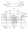
図4は、本発明に係る半導体装置用ソケットの第2実施例の全体構成を概略的に示す。
図4は、後述する半導体素子が未だ装着されていない状態を示す。
なお、図4に示される例、および、後述する他の実施例において、図2における例において、同一とされる構成要素について同一の符号を付して示し、その重複説明を省略する。
FIG. 4 schematically shows the overall configuration of a second embodiment of the socket for a semiconductor device according to the present invention.
FIG. 4 shows a state where a semiconductor element to be described later is not yet mounted.
In the example shown in FIG. 4 and other examples to be described later, the same reference numerals are given to the same components in the example in FIG.
図2に示される例においては、案内部材20の最大移動量が、その係合ピン20Paまたは20Pbがポスト部24Pに当接することにより、規制されるものであるが、図4に示される例においては、案内部材40の最大移動量が、案内部材40の外周部における移動方向に略直交する端面とソケット本体24の収容部24aの内周面とが当接することにより、規制され、かつ、コンタクト移動用部材48と案内部材40との間の相互の連結部に所定の隙間CL’(=A−B)が形成されるものとされる。
In the example shown in FIG. 2, the maximum movement amount of the
案内部材40の底部を相対的に移動し得るように支持するコンタクト移動用部材48は、ソケット本体24の収容部24aに、各コンタクト端子26aiの可動接点部26Mおよび26Fの運動方向に沿って移動可能に配されている。
The
コンタクト移動用部材48は、各コンタクト端子26aiの可動接点部26Mおよび26Fが突出する開口部48bを内部に有している。各開口部48bは、それぞれ、図示が省略される隔壁により仕切られている。その隔壁は、紙面に略垂直方向に所定の間隔で各コンタクト端子26aiに対応して形成されている。
The
コンタクト移動用部材48において、各列ごとの各開口部48bには、開口部48bを複数に分割し、かつ、可動接点部26Mと可動接点部26Fとを仕切るように形成される可動接点押圧部48Pが複数個、設けられている。
In the
また、コンタクト移動用部材48において案内部材40の底部が摺動される面には、後述する案内部材40の突起部40Pが移動可能に係合される凹部48aが設けられている。各凹部48aは、それぞれ、案内部材40の突起部40Pを案内部材40の移動方向に沿って案内するものとされる。その際、図4に示されるように、カバー部材32が最上端位置にある初期状態において、案内部材40の突起部40Pの外周面と凹部48aを形成する内周面との間に所定の隙間CL’(=A−B)(A:コンタクト移動用部材48(可動接点押圧部48P)の最大移動量、B:追従する半導体素子36の(半導体素子36の各電極36a)の最大移動量)が図4において右側に形成されている。また、図4に示されるように、コンタクト移動用部材48における移動方向に対し略直交する一方の端面とソケット本体24の収容部24aの内周面とが隙間なく当接するものとされる。
In addition, a
さらに、コンタクト移動用部材48の一端とソケット本体24の収容部24aの内周部との間には、図示が省略されるが、コンタクト移動用部材48を図4において二点鎖線で示される位置から図4において実線で示される位置までに戻すべく付勢する付勢部材が設けられている。
Further, although not shown between the one end of the
さらに、コンタクト移動用部材48は、特許文献2にも示されるような、レバーおよびピンからなる駆動機構に連結されている。その備えられる駆動機構のレバーの一端は、カバー部材32の端部に当接している。
Further, the
これにより、図4に示される矢印Dの示す方向に沿った、カバー部材32の下降動作に応じてコンタクト移動用部材48が図4に示される矢印Mの示す方向に、付勢手段の付勢力に抗して移動せしめられるとき、可動接点押圧部48Pが各コンタクト端子26aiの可動接点部26Mを可動接点部26Fに対して離隔させるように移動せしめられる。一方、カバー部材32の上昇動作に応じて図4の矢印Mの示す方向とは反対方向に、コンタクト移動用部材48が付勢手段の付勢力および可動接点部26Mの復元力により移動せしめられる。
Accordingly, the urging force of the urging means is applied to the
案内部材40は、図4に示されるように、その中央部に、半導体素子36が装着される収容部40aを有している。収容部40aの内周面は、略正方形の半導体素子36の各端面がそれぞれ対向する平坦面と、上端面とその平坦面とを結合する斜面部と、平坦面に交叉する底面部とにより形成されている。収容部40aの内周面の寸法は、所定の公差をもって装着される半導体素子36の外形寸法よりも大に設定されている。即ち、図4に二点鎖線で示されるように、コンタクト移動用部材48が最大に移動したとき、半導体素子36の各端面と案内部材20の平坦面との間の隙間Cの値は、図2に示される位置から図1に示される位置までのコンタクト移動用部材48(可動接点押圧部48P)の最大移動量Aと追従する半導体素子36の(半導体素子36の各電極36a)の最大移動量Bとの差の値(A−B)よりも小に設定されている(C<A−B)。なお、最大移動量Bの値は、最大移動量Aの値よりも小なる値とされる。
また、案内部材40における下端には、それぞれ、上述の凹部48bに案内される突起部40Pが設けられている。
As shown in FIG. 4, the
In addition, the lower end of the
図4に示される状態、即ち、案内部材40およびコンタクト移動用部材48における移動方向に対し略直交する一方の端面がソケット本体24の収容部24の内周面に当接しているとき、案内部材40における他方の端面と収容部24aの内周面との隙間が、上述の最大移動量Bの値となるように設定されている。その際、コンタクト移動用部材48の端面が収容部24aの内周面に当接しているのでコンタクト移動用部材48が所定位置に位置決めされることとなる。
In the state shown in FIG. 4, that is, when one end face substantially perpendicular to the moving direction of the
一方、案内部材40における突起部40Pとコンタクト移動用部材48の凹部48bを形成する周縁との間には、コンタクト移動用部材48(可動接点押圧部48P)の最大移動量Aと追従する半導体素子36の(半導体素子36の各電極36a)の最大移動量Bとの差の値に応じた隙間CL’(A−B)が形成されている。
On the other hand, a semiconductor element that follows the maximum movement amount A of the contact moving member 48 (movable
また、図4に二点鎖線で示される状態においても、即ち、案内部材40における移動方向に対し略直交する一方の端面が収容部24aの内周面に当接しているとき、案内部材40における他方の端面と収容部24aの内周面との隙間が、上述の最大移動量Bの値となるように設定されている。その際、案内部材40における突起部40Pは、上述と同様に、コンタクト移動用部材48の凹部48aの周縁に当接しているのでコンタクト移動用部材48が所定位置に位置決めされることとなる。その際、案内部材40の突起部40Pとコンタクト移動用部材48の凹部48aの周縁との間には、コンタクト移動用部材48(可動接点押圧部48P)の最大移動量Aと追従する半導体素子36の(半導体素子36の各電極36a)の最大移動量Bとの差の値に応じた隙間CL’(CL’=A−B)が図4において左側に形成されることとなる。
従って、斯かる構成においても、上述の第1の実施例と同様な作用効果が得られることとなる。
Further, even in the state indicated by the two-dot chain line in FIG. 4, that is, when one end surface substantially orthogonal to the moving direction of the
Accordingly, even in such a configuration, the same operational effects as those of the first embodiment described above can be obtained.
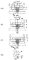
図5は、本発明に係る半導体装置用ソケットの第3実施例の全体構成を概略的に示す。
図5は、半導体素子36が装着されていない状態を示す。
図2に示される例においては、カバー部材32がソケット本体24に対して昇降動可能に支持されているが、図5では、その代わりに、カバー部材52がソケット本体24とは別体に設けられる構成とされる。即ち、カバー部材52は、図示が省略されるロボットのハンドラーHAに保持されるもとで、ソケット本体24に対し近接または離隔可能に支持されることとなる。
FIG. 5 schematically shows an overall configuration of a third embodiment of the socket for a semiconductor device according to the present invention.
FIG. 5 shows a state in which the
In the example shown in FIG. 2, the
斯かる構成において、半導体素子36が装着される場合、ロボットのハンドラーHAに保持されるカバー部材52の下端が、上述した特許文献2にも示されるような、レバーおよびピンからなる駆動機構のレバーの一端に、図5に破線で示されるように当接するものとされる。これにより、案内部材20が上述の図1に示される状態と同様な状態まで移動せしめられることとなる。
In such a configuration, when the
そして、半導体素子36が案内部材20の収容部20a内に装着された後、図5に実線で示されるように、ロボットのハンドラーHAに保持されるカバー部材52が、ソケット本体24に対し離隔され、半導体素子36は、上述の図3に示される状態と同様な状態で保持されることとなる。
従って、本実施例においても、上述の第1の実施例と同様な作用効果が得られることとなる。
Then, after the
Therefore, also in this embodiment, the same effect as that of the first embodiment described above can be obtained.
図6は、本発明に係る半導体装置用ソケットの第4実施例の全体構成を概略的に示す。 図6は、カバー部材32が最下端位置まで下降せしめられ、半導体素子36が載置された直後の状態を示す。
FIG. 6 schematically shows the overall configuration of a fourth embodiment of the socket for a semiconductor device according to the present invention. FIG. 6 shows a state immediately after the
図2に示される例においては、案内部材20がコンタクト移動用部材28の収容部28a内に移動可能に支持されているが、その代わりに、図6においては、案内部材50がソケット本体24とは別体に設けられる構成とされる。即ち、係合ピン50Pbおよび50Paを有する案内部材50は、図示が省略されるロボットのハンドラーHAに保持されるもとで、コンタクト移動用部材28の収容部28aに対し近接または離隔可能に支持されることとなる。このような構成は、例えば、特許文献3乃至13にも開示されている。
In the example shown in FIG. 2, the
斯かる構成において、半導体素子36が装着される場合、図6に示されるように、ロボットのハンドラーHAに保持される案内部材50の下端が、コンタクト移動用部材28の収容部28aの底面に当接されるとともに、図5に破線で示されるようにその係合ピン50Pbがポスト部24Pに当接されるもとで、カバー部材32が最下端位置まで下降せしめられる。その際、半導体素子36の各端面と案内部材50の平坦面との間の隙間Cの値は、上述したようなコンタクト移動用部材28(可動接点押圧部28P)の最大移動量Aと追従する半導体素子36の(半導体素子36の各電極36a)の最大移動量Bとの差の値(A−B)よりも小に設定されている(C<A−B)。なお、最大移動量Bの値は、最大移動量Aの値よりも小なる値とされる。
これにより、案内部材50が上述の図1に示される状態と同様な状態まで移動せしめられることとなる。
In such a configuration, when the
As a result, the
そして、半導体素子36が案内部材50の収容部50a内に装着された後、カバー部材32が、ソケット本体24に対し離隔され、半導体素子36は、上述の図3に示される状態と同様な状態で保持されることとなる。
従って、本実施例においても、上述の第1の実施例と同様な作用効果が得られることとなる。
Then, after the
Therefore, also in this embodiment, the same effect as that of the first embodiment described above can be obtained.
なお、上述の第3実施例および第4実施例においては、それぞれ、カバー部材52および案内部材50が、ソケット本体24およびコンタクト移動用部材28に対し別体となるように構成されているが、斯かる例に限られることなく、カバー部材52および案内部材50の双方が、ソケット本体24およびコンタクト移動用部材28に対し別体となるように構成されてもよい。
In the third and fourth embodiments described above, the
20、40、50 案内部材
20Pa、20Pb 係合ピン
24 ソケット本体
24P ポスト部
28、48 コンタクト移動用部材
36 半導体素子
40P 突起部
48a 凹
C,CL、CL’ 隙間
20, 40, 50 Guide member 20Pa,
Claims (5)
前記ソケット本体内に前記一対の可動接点における近接または離隔方向に沿って移動可能に配され前記コンタクト端子の前記一対の可動接点を前記半導体装置の端子に近接または離隔させる押圧部を有する可動接点移動用部材と、
前記可動接点移動用部材の収容部に配され、前記半導体装置を案内するとともに該半導体装置の端子を前記一対の可動接点に対し位置決めすることにより、前記半導体装置の端面との相互間に所定の隙間を形成する案内部材と、
前記一対の可動接点における近接または離隔方向に沿った前記案内部材の最大移動量を規制する移動量規制部と、を備え、
前記所定の隙間が、前記案内部材の最大移動量と前記半導体装置の最大移動量との差に応じて設定されるとともに、前記移動量規制部が前記一対の可動接点における近接または離隔方向に沿った前記案内部材の最大移動量を規制するとき、前記半導体装置の最大移動量に対応した隙間が、該案内部材の端面と該移動量規制部との間に設定され、前記移動量規制部が、前記案内部材の最大移動量を該半導体装置の最大移動量に規制することを特徴とする半導体装置用ソケット。 A socket body that supports a base end portion of a contact terminal having a pair of movable contacts that are sandwiched between and electrically connected to each other and electrically connected to each other and released from each other .
A movable contact movement having a pressing portion disposed in the socket main body so as to be movable along a proximity or separation direction of the pair of movable contacts and causing the pair of movable contacts of the contact terminal to approach or separate from the terminals of the semiconductor device. Members for
The movable contact moving member is disposed in the receiving portion, guides the semiconductor device, and positions the terminals of the semiconductor device with respect to the pair of movable contacts. A guide member that forms a gap;
A movement amount restricting portion for restricting the maximum movement amount of the guide member along the proximity or separation direction in the pair of movable contacts ,
The predetermined gap is set according to a difference between the maximum movement amount of the guide member and the maximum movement amount of the semiconductor device, and the movement amount regulating portion is along the approach or separation direction of the pair of movable contacts. When the maximum movement amount of the guide member is restricted, a gap corresponding to the maximum movement amount of the semiconductor device is set between the end surface of the guide member and the movement amount restriction portion, and the movement amount restriction portion is The semiconductor device socket is characterized in that a maximum movement amount of the guide member is restricted to a maximum movement amount of the semiconductor device.
Priority Applications (2)
| Application Number | Priority Date | Filing Date | Title |
|---|---|---|---|
| JP2003423833A JP4098231B2 (en) | 2003-12-19 | 2003-12-19 | Socket for semiconductor device |
| US11/013,800 US6976863B2 (en) | 2003-12-19 | 2004-12-17 | Semiconductor device socket |
Applications Claiming Priority (1)
| Application Number | Priority Date | Filing Date | Title |
|---|---|---|---|
| JP2003423833A JP4098231B2 (en) | 2003-12-19 | 2003-12-19 | Socket for semiconductor device |
Publications (2)
| Publication Number | Publication Date |
|---|---|
| JP2005183235A JP2005183235A (en) | 2005-07-07 |
| JP4098231B2 true JP4098231B2 (en) | 2008-06-11 |
Family
ID=34675375
Family Applications (1)
| Application Number | Title | Priority Date | Filing Date |
|---|---|---|---|
| JP2003423833A Expired - Lifetime JP4098231B2 (en) | 2003-12-19 | 2003-12-19 | Socket for semiconductor device |
Country Status (2)
| Country | Link |
|---|---|
| US (1) | US6976863B2 (en) |
| JP (1) | JP4098231B2 (en) |
Families Citing this family (8)
| Publication number | Priority date | Publication date | Assignee | Title |
|---|---|---|---|---|
| JP4312685B2 (en) * | 2004-08-31 | 2009-08-12 | 山一電機株式会社 | Semiconductor device attaching / detaching method, semiconductor device attaching / detaching device using the same, and semiconductor device socket |
| JP4471941B2 (en) * | 2005-03-10 | 2010-06-02 | 山一電機株式会社 | Socket for semiconductor device |
| US7172450B1 (en) * | 2006-01-11 | 2007-02-06 | Qualitau, Inc. | High temperature open ended zero insertion force (ZIF) test socket |
| JP2009036679A (en) * | 2007-08-02 | 2009-02-19 | Yamaichi Electronics Co Ltd | Socket for semiconductor device |
| JP4495200B2 (en) * | 2007-09-28 | 2010-06-30 | 山一電機株式会社 | Socket for semiconductor device |
| JP2010118275A (en) * | 2008-11-13 | 2010-05-27 | Yamaichi Electronics Co Ltd | Socket for semiconductor device |
| KR20130111066A (en) * | 2012-03-30 | 2013-10-10 | 삼성전자주식회사 | Method for process proximity correction |
| USD788722S1 (en) | 2014-07-17 | 2017-06-06 | Advantest Corporation | Socket for an electronic device testing apparatus |
Family Cites Families (24)
| Publication number | Priority date | Publication date | Assignee | Title |
|---|---|---|---|---|
| JPH0647881A (en) | 1992-07-29 | 1994-02-22 | Daicel Chem Ind Ltd | Fire retardant laminate sheet |
| JP2985532B2 (en) | 1992-09-14 | 1999-12-06 | 日立電子エンジニアリング株式会社 | IC device transfer method |
| JP3227968B2 (en) | 1993-12-29 | 2001-11-12 | 安藤電気株式会社 | Multiple simultaneous contact mechanism of TSOP IC |
| US5419710A (en) * | 1994-06-10 | 1995-05-30 | Pfaff; Wayne K. | Mounting apparatus for ball grid array device |
| JPH08233899A (en) | 1995-02-28 | 1996-09-13 | Ando Electric Co Ltd | Contact mechanism for ic |
| JPH08334546A (en) | 1995-06-06 | 1996-12-17 | Hitachi Ltd | Testing apparatus for semiconductor device |
| JPH0951029A (en) | 1995-08-07 | 1997-02-18 | Hitachi Ltd | Semiconductor manufacturing method and device and carrier device |
| JP2940858B2 (en) | 1995-10-18 | 1999-08-25 | 株式会社アドバンテスト | IC test equipment |
| JPH10160797A (en) | 1996-12-03 | 1998-06-19 | M C Electron Kk | Positioning insertion device of ic to be tested into socket of ic handler |
| JP3059946B2 (en) | 1997-05-01 | 2000-07-04 | 山一電機株式会社 | IC socket |
| JP3270716B2 (en) * | 1997-07-04 | 2002-04-02 | 日本テキサス・インスツルメンツ株式会社 | Socket and mounting method of semiconductor device |
| JPH11333775A (en) | 1998-05-29 | 1999-12-07 | Advantest Corp | Parts sucking device, parts handling device, and parts testing device |
| JP2904782B1 (en) * | 1998-07-29 | 1999-06-14 | 山一電機株式会社 | IC socket |
| JP4087012B2 (en) * | 1999-05-31 | 2008-05-14 | 株式会社エンプラス | Socket for electrical parts |
| JP3720657B2 (en) * | 1999-11-29 | 2005-11-30 | 株式会社エンプラス | Socket for electrical parts |
| JP2001242218A (en) | 2000-02-29 | 2001-09-07 | Sharp Corp | Ic socket |
| JP2002071750A (en) | 2000-08-29 | 2002-03-12 | Enplas Corp | Carrier and pusher for handler device and handler device |
| US6796823B1 (en) * | 2001-05-21 | 2004-09-28 | Yamaichi Electronics Co., Ltd. | Socket for electronic element |
| JP3488700B2 (en) * | 2001-05-23 | 2004-01-19 | 山一電機株式会社 | Driving method of contact terminal and socket for semiconductor device using the same |
| JP2003017206A (en) * | 2001-06-27 | 2003-01-17 | Yamaichi Electronics Co Ltd | Socket for semiconductor device |
| JP3703741B2 (en) * | 2001-07-04 | 2005-10-05 | 山一電機株式会社 | IC socket |
| JP3678182B2 (en) * | 2001-08-10 | 2005-08-03 | 山一電機株式会社 | Socket for semiconductor device |
| JP3745667B2 (en) * | 2001-10-09 | 2006-02-15 | 山一電機株式会社 | IC socket |
| JP3866123B2 (en) * | 2002-03-11 | 2007-01-10 | 株式会社エンプラス | Socket for electrical parts |
-
2003
- 2003-12-19 JP JP2003423833A patent/JP4098231B2/en not_active Expired - Lifetime
-
2004
- 2004-12-17 US US11/013,800 patent/US6976863B2/en active Active
Also Published As
| Publication number | Publication date |
|---|---|
| US20050136721A1 (en) | 2005-06-23 |
| JP2005183235A (en) | 2005-07-07 |
| US6976863B2 (en) | 2005-12-20 |
Similar Documents
| Publication | Publication Date | Title |
|---|---|---|
| KR100778964B1 (en) | Semiconductor device-socket | |
| JP4073439B2 (en) | Socket for semiconductor device | |
| US7118386B2 (en) | Socket for semiconductor device | |
| JP2003059602A (en) | Socket for semiconductor device | |
| JP4911495B2 (en) | Socket for semiconductor integrated circuit | |
| JP4098231B2 (en) | Socket for semiconductor device | |
| JP2006294308A (en) | Socket for electrical component | |
| US6707309B2 (en) | Semiconductor device-socket | |
| US7511375B2 (en) | Semiconductor device carrier unit and semiconductor socket provided therewith | |
| JP3488700B2 (en) | Driving method of contact terminal and socket for semiconductor device using the same | |
| JP5140659B2 (en) | Socket for electrical parts | |
| US6793512B2 (en) | Socket for semiconductor device | |
| JP5518391B2 (en) | Socket for electrical parts | |
| JP2007287381A (en) | Socket for electrical component | |
| JP5168671B2 (en) | Socket for semiconductor device provided with contact block | |
| JP2005134373A (en) | Connection device using spiral contactor | |
| JP3784787B2 (en) | Socket for semiconductor device | |
| JP3150318U (en) | IC socket | |
| JP2008077988A (en) | Contact terminal and socket for semiconductor device equipped with it | |
| JP2019021399A (en) | Electrical component socket | |
| JP5269303B2 (en) | Socket for electrical parts | |
| JP4754458B2 (en) | Electronic component testing equipment | |
| JP2011033527A (en) | Substrate inspection device | |
| JP4962794B2 (en) | Connector device and semiconductor test system | |
| JP6700690B2 (en) | Socket for electrical parts |
Legal Events
| Date | Code | Title | Description |
|---|---|---|---|
| A621 | Written request for application examination |
Free format text: JAPANESE INTERMEDIATE CODE: A621 Effective date: 20050617 |
|
| A977 | Report on retrieval |
Free format text: JAPANESE INTERMEDIATE CODE: A971007 Effective date: 20071106 |
|
| A131 | Notification of reasons for refusal |
Free format text: JAPANESE INTERMEDIATE CODE: A131 Effective date: 20071109 |
|
| A521 | Request for written amendment filed |
Free format text: JAPANESE INTERMEDIATE CODE: A523 Effective date: 20080108 |
|
| TRDD | Decision of grant or rejection written | ||
| A01 | Written decision to grant a patent or to grant a registration (utility model) |
Free format text: JAPANESE INTERMEDIATE CODE: A01 Effective date: 20080304 |
|
| A61 | First payment of annual fees (during grant procedure) |
Free format text: JAPANESE INTERMEDIATE CODE: A61 Effective date: 20080312 |
|
| R150 | Certificate of patent or registration of utility model |
Ref document number: 4098231 Country of ref document: JP Free format text: JAPANESE INTERMEDIATE CODE: R150 Free format text: JAPANESE INTERMEDIATE CODE: R150 |
|
| FPAY | Renewal fee payment (event date is renewal date of database) |
Free format text: PAYMENT UNTIL: 20110321 Year of fee payment: 3 |
|
| FPAY | Renewal fee payment (event date is renewal date of database) |
Free format text: PAYMENT UNTIL: 20110321 Year of fee payment: 3 |
|
| FPAY | Renewal fee payment (event date is renewal date of database) |
Free format text: PAYMENT UNTIL: 20110321 Year of fee payment: 3 |
|
| FPAY | Renewal fee payment (event date is renewal date of database) |
Free format text: PAYMENT UNTIL: 20120321 Year of fee payment: 4 |
|
| R250 | Receipt of annual fees |
Free format text: JAPANESE INTERMEDIATE CODE: R250 |
|
| FPAY | Renewal fee payment (event date is renewal date of database) |
Free format text: PAYMENT UNTIL: 20120321 Year of fee payment: 4 |
|
| FPAY | Renewal fee payment (event date is renewal date of database) |
Free format text: PAYMENT UNTIL: 20130321 Year of fee payment: 5 |
|
| R250 | Receipt of annual fees |
Free format text: JAPANESE INTERMEDIATE CODE: R250 |
|
| FPAY | Renewal fee payment (event date is renewal date of database) |
Free format text: PAYMENT UNTIL: 20130321 Year of fee payment: 5 |
|
| FPAY | Renewal fee payment (event date is renewal date of database) |
Free format text: PAYMENT UNTIL: 20130321 Year of fee payment: 5 |
|
| FPAY | Renewal fee payment (event date is renewal date of database) |
Free format text: PAYMENT UNTIL: 20130321 Year of fee payment: 5 |
|
| FPAY | Renewal fee payment (event date is renewal date of database) |
Free format text: PAYMENT UNTIL: 20140321 Year of fee payment: 6 |
|
| R250 | Receipt of annual fees |
Free format text: JAPANESE INTERMEDIATE CODE: R250 |
|
| R250 | Receipt of annual fees |
Free format text: JAPANESE INTERMEDIATE CODE: R250 |
|
| R250 | Receipt of annual fees |
Free format text: JAPANESE INTERMEDIATE CODE: R250 |
|
| R250 | Receipt of annual fees |
Free format text: JAPANESE INTERMEDIATE CODE: R250 |
|
| R250 | Receipt of annual fees |
Free format text: JAPANESE INTERMEDIATE CODE: R250 |
|
| R250 | Receipt of annual fees |
Free format text: JAPANESE INTERMEDIATE CODE: R250 |
|
| R250 | Receipt of annual fees |
Free format text: JAPANESE INTERMEDIATE CODE: R250 |
|
| R250 | Receipt of annual fees |
Free format text: JAPANESE INTERMEDIATE CODE: R250 |
|
| R250 | Receipt of annual fees |
Free format text: JAPANESE INTERMEDIATE CODE: R250 |
|
| R250 | Receipt of annual fees |
Free format text: JAPANESE INTERMEDIATE CODE: R250 |
|
| R250 | Receipt of annual fees |
Free format text: JAPANESE INTERMEDIATE CODE: R250 |
|
| EXPY | Cancellation because of completion of term |