JP4085998B2 - Waste heat recovery device - Google Patents
Waste heat recovery device Download PDFInfo
- Publication number
- JP4085998B2 JP4085998B2 JP2004083049A JP2004083049A JP4085998B2 JP 4085998 B2 JP4085998 B2 JP 4085998B2 JP 2004083049 A JP2004083049 A JP 2004083049A JP 2004083049 A JP2004083049 A JP 2004083049A JP 4085998 B2 JP4085998 B2 JP 4085998B2
- Authority
- JP
- Japan
- Prior art keywords
- catalyst
- heat
- heat recovery
- exhaust gas
- exhaust
- Prior art date
- Legal status (The legal status is an assumption and is not a legal conclusion. Google has not performed a legal analysis and makes no representation as to the accuracy of the status listed.)
- Expired - Fee Related
Links
- 238000011084 recovery Methods 0.000 title claims description 159
- 239000002918 waste heat Substances 0.000 title description 7
- 239000003054 catalyst Substances 0.000 claims description 221
- 238000006243 chemical reaction Methods 0.000 claims description 84
- 230000004913 activation Effects 0.000 claims description 48
- 238000002485 combustion reaction Methods 0.000 claims description 9
- 230000005611 electricity Effects 0.000 claims description 5
- 239000007789 gas Substances 0.000 description 121
- 238000010248 power generation Methods 0.000 description 41
- 238000010586 diagram Methods 0.000 description 10
- 238000001816 cooling Methods 0.000 description 9
- 239000000498 cooling water Substances 0.000 description 7
- 238000011144 upstream manufacturing Methods 0.000 description 7
- 238000010792 warming Methods 0.000 description 7
- MWUXSHHQAYIFBG-UHFFFAOYSA-N nitrogen oxide Inorganic materials O=[N] MWUXSHHQAYIFBG-UHFFFAOYSA-N 0.000 description 6
- 238000000746 purification Methods 0.000 description 4
- UGFAIRIUMAVXCW-UHFFFAOYSA-N Carbon monoxide Chemical compound [O+]#[C-] UGFAIRIUMAVXCW-UHFFFAOYSA-N 0.000 description 2
- 229910002091 carbon monoxide Inorganic materials 0.000 description 2
- 230000006866 deterioration Effects 0.000 description 2
- 229930195733 hydrocarbon Natural products 0.000 description 2
- 150000002430 hydrocarbons Chemical class 0.000 description 2
- 239000000126 substance Substances 0.000 description 2
- DGAQECJNVWCQMB-PUAWFVPOSA-M Ilexoside XXIX Chemical compound C[C@@H]1CC[C@@]2(CC[C@@]3(C(=CC[C@H]4[C@]3(CC[C@@H]5[C@@]4(CC[C@@H](C5(C)C)OS(=O)(=O)[O-])C)C)[C@@H]2[C@]1(C)O)C)C(=O)O[C@H]6[C@@H]([C@H]([C@@H]([C@H](O6)CO)O)O)O.[Na+] DGAQECJNVWCQMB-PUAWFVPOSA-M 0.000 description 1
- ZLMJMSJWJFRBEC-UHFFFAOYSA-N Potassium Chemical compound [K] ZLMJMSJWJFRBEC-UHFFFAOYSA-N 0.000 description 1
- 230000005678 Seebeck effect Effects 0.000 description 1
- 229910052792 caesium Inorganic materials 0.000 description 1
- TVFDJXOCXUVLDH-UHFFFAOYSA-N caesium atom Chemical compound [Cs] TVFDJXOCXUVLDH-UHFFFAOYSA-N 0.000 description 1
- 230000015556 catabolic process Effects 0.000 description 1
- 238000006731 degradation reaction Methods 0.000 description 1
- 230000000694 effects Effects 0.000 description 1
- 230000020169 heat generation Effects 0.000 description 1
- 230000002093 peripheral effect Effects 0.000 description 1
- 229910052700 potassium Inorganic materials 0.000 description 1
- 239000011591 potassium Substances 0.000 description 1
- 239000002994 raw material Substances 0.000 description 1
- 229910052708 sodium Inorganic materials 0.000 description 1
- 239000011734 sodium Substances 0.000 description 1
Images


Classifications
-
- F—MECHANICAL ENGINEERING; LIGHTING; HEATING; WEAPONS; BLASTING
- F01—MACHINES OR ENGINES IN GENERAL; ENGINE PLANTS IN GENERAL; STEAM ENGINES
- F01N—GAS-FLOW SILENCERS OR EXHAUST APPARATUS FOR MACHINES OR ENGINES IN GENERAL; GAS-FLOW SILENCERS OR EXHAUST APPARATUS FOR INTERNAL COMBUSTION ENGINES
- F01N3/00—Exhaust or silencing apparatus having means for purifying, rendering innocuous, or otherwise treating exhaust
- F01N3/08—Exhaust or silencing apparatus having means for purifying, rendering innocuous, or otherwise treating exhaust for rendering innocuous
- F01N3/10—Exhaust or silencing apparatus having means for purifying, rendering innocuous, or otherwise treating exhaust for rendering innocuous by thermal or catalytic conversion of noxious components of exhaust
- F01N3/18—Exhaust or silencing apparatus having means for purifying, rendering innocuous, or otherwise treating exhaust for rendering innocuous by thermal or catalytic conversion of noxious components of exhaust characterised by methods of operation; Control
- F01N3/20—Exhaust or silencing apparatus having means for purifying, rendering innocuous, or otherwise treating exhaust for rendering innocuous by thermal or catalytic conversion of noxious components of exhaust characterised by methods of operation; Control specially adapted for catalytic conversion ; Methods of operation or control of catalytic converters
- F01N3/2006—Periodically heating or cooling catalytic reactors, e.g. at cold starting or overheating
- F01N3/2013—Periodically heating or cooling catalytic reactors, e.g. at cold starting or overheating using electric or magnetic heating means
-
- F—MECHANICAL ENGINEERING; LIGHTING; HEATING; WEAPONS; BLASTING
- F01—MACHINES OR ENGINES IN GENERAL; ENGINE PLANTS IN GENERAL; STEAM ENGINES
- F01N—GAS-FLOW SILENCERS OR EXHAUST APPARATUS FOR MACHINES OR ENGINES IN GENERAL; GAS-FLOW SILENCERS OR EXHAUST APPARATUS FOR INTERNAL COMBUSTION ENGINES
- F01N5/00—Exhaust or silencing apparatus combined or associated with devices profiting by exhaust energy
- F01N5/02—Exhaust or silencing apparatus combined or associated with devices profiting by exhaust energy the devices using heat
- F01N5/025—Exhaust or silencing apparatus combined or associated with devices profiting by exhaust energy the devices using heat the device being thermoelectric generators
-
- F—MECHANICAL ENGINEERING; LIGHTING; HEATING; WEAPONS; BLASTING
- F28—HEAT EXCHANGE IN GENERAL
- F28D—HEAT-EXCHANGE APPARATUS, NOT PROVIDED FOR IN ANOTHER SUBCLASS, IN WHICH THE HEAT-EXCHANGE MEDIA DO NOT COME INTO DIRECT CONTACT
- F28D15/00—Heat-exchange apparatus with the intermediate heat-transfer medium in closed tubes passing into or through the conduit walls ; Heat-exchange apparatus employing intermediate heat-transfer medium or bodies
- F28D15/02—Heat-exchange apparatus with the intermediate heat-transfer medium in closed tubes passing into or through the conduit walls ; Heat-exchange apparatus employing intermediate heat-transfer medium or bodies in which the medium condenses and evaporates, e.g. heat pipes
- F28D15/0266—Heat-exchange apparatus with the intermediate heat-transfer medium in closed tubes passing into or through the conduit walls ; Heat-exchange apparatus employing intermediate heat-transfer medium or bodies in which the medium condenses and evaporates, e.g. heat pipes with separate evaporating and condensing chambers connected by at least one conduit; Loop-type heat pipes; with multiple or common evaporating or condensing chambers
-
- F—MECHANICAL ENGINEERING; LIGHTING; HEATING; WEAPONS; BLASTING
- F28—HEAT EXCHANGE IN GENERAL
- F28D—HEAT-EXCHANGE APPARATUS, NOT PROVIDED FOR IN ANOTHER SUBCLASS, IN WHICH THE HEAT-EXCHANGE MEDIA DO NOT COME INTO DIRECT CONTACT
- F28D15/00—Heat-exchange apparatus with the intermediate heat-transfer medium in closed tubes passing into or through the conduit walls ; Heat-exchange apparatus employing intermediate heat-transfer medium or bodies
- F28D15/02—Heat-exchange apparatus with the intermediate heat-transfer medium in closed tubes passing into or through the conduit walls ; Heat-exchange apparatus employing intermediate heat-transfer medium or bodies in which the medium condenses and evaporates, e.g. heat pipes
- F28D15/0275—Arrangements for coupling heat-pipes together or with other structures, e.g. with base blocks; Heat pipe cores
-
- F—MECHANICAL ENGINEERING; LIGHTING; HEATING; WEAPONS; BLASTING
- F28—HEAT EXCHANGE IN GENERAL
- F28F—DETAILS OF HEAT-EXCHANGE AND HEAT-TRANSFER APPARATUS, OF GENERAL APPLICATION
- F28F1/00—Tubular elements; Assemblies of tubular elements
- F28F1/10—Tubular elements and assemblies thereof with means for increasing heat-transfer area, e.g. with fins, with projections, with recesses
- F28F1/12—Tubular elements and assemblies thereof with means for increasing heat-transfer area, e.g. with fins, with projections, with recesses the means being only outside the tubular element
-
- H—ELECTRICITY
- H10—SEMICONDUCTOR DEVICES; ELECTRIC SOLID-STATE DEVICES NOT OTHERWISE PROVIDED FOR
- H10N—ELECTRIC SOLID-STATE DEVICES NOT OTHERWISE PROVIDED FOR
- H10N10/00—Thermoelectric devices comprising a junction of dissimilar materials, i.e. devices exhibiting Seebeck or Peltier effects
- H10N10/10—Thermoelectric devices comprising a junction of dissimilar materials, i.e. devices exhibiting Seebeck or Peltier effects operating with only the Peltier or Seebeck effects
- H10N10/13—Thermoelectric devices comprising a junction of dissimilar materials, i.e. devices exhibiting Seebeck or Peltier effects operating with only the Peltier or Seebeck effects characterised by the heat-exchanging means at the junction
-
- F—MECHANICAL ENGINEERING; LIGHTING; HEATING; WEAPONS; BLASTING
- F28—HEAT EXCHANGE IN GENERAL
- F28D—HEAT-EXCHANGE APPARATUS, NOT PROVIDED FOR IN ANOTHER SUBCLASS, IN WHICH THE HEAT-EXCHANGE MEDIA DO NOT COME INTO DIRECT CONTACT
- F28D21/00—Heat-exchange apparatus not covered by any of the groups F28D1/00 - F28D20/00
- F28D21/0001—Recuperative heat exchangers
- F28D21/0003—Recuperative heat exchangers the heat being recuperated from exhaust gases
-
- Y—GENERAL TAGGING OF NEW TECHNOLOGICAL DEVELOPMENTS; GENERAL TAGGING OF CROSS-SECTIONAL TECHNOLOGIES SPANNING OVER SEVERAL SECTIONS OF THE IPC; TECHNICAL SUBJECTS COVERED BY FORMER USPC CROSS-REFERENCE ART COLLECTIONS [XRACs] AND DIGESTS
- Y02—TECHNOLOGIES OR APPLICATIONS FOR MITIGATION OR ADAPTATION AGAINST CLIMATE CHANGE
- Y02T—CLIMATE CHANGE MITIGATION TECHNOLOGIES RELATED TO TRANSPORTATION
- Y02T10/00—Road transport of goods or passengers
- Y02T10/10—Internal combustion engine [ICE] based vehicles
- Y02T10/12—Improving ICE efficiencies
Landscapes
- Engineering & Computer Science (AREA)
- Mechanical Engineering (AREA)
- General Engineering & Computer Science (AREA)
- Physics & Mathematics (AREA)
- Chemical & Material Sciences (AREA)
- Thermal Sciences (AREA)
- Sustainable Development (AREA)
- Combustion & Propulsion (AREA)
- Life Sciences & Earth Sciences (AREA)
- Chemical Kinetics & Catalysis (AREA)
- Toxicology (AREA)
- Health & Medical Sciences (AREA)
- Geometry (AREA)
- Exhaust Gas After Treatment (AREA)
Description
本発明は、たとえばハイブリッド車などの車両などに用いられ、気体中に含まれる熱エネルギーを電気エネルギーに変換するために、気体中に含まれる熱エネルギーを回収する排熱回収装置に関する。 The present invention relates to an exhaust heat recovery apparatus that is used in vehicles such as hybrid vehicles and that recovers heat energy contained in gas in order to convert heat energy contained in gas into electric energy.
自動車のエンジンから排出される排気ガスなどには、熱エネルギーが含まれてため、排気ガスをそのまま捨てるとエネルギーの無駄となる。そこで、排気ガスに含まれる熱エネルギーを排熱回収装置によって回収し、熱エネルギーを熱電変換素子で電気エネルギーに変換し、たとえばバッテリーに充電しておく排熱回収装置がある。 Exhaust gas discharged from an automobile engine contains thermal energy, so if the exhaust gas is discarded as it is, energy is wasted. Therefore, there is an exhaust heat recovery device that recovers thermal energy contained in exhaust gas by an exhaust heat recovery device, converts the thermal energy into electrical energy by a thermoelectric conversion element, and charges a battery, for example.
このような排熱回収装置として、従来、特開2003−65045号公報に開示された排気熱回収装置がある。この排気熱回収装置は、エンジンの排気系の構成部品にヒートパイプを接続し、このヒートパイプに熱電素子(熱電変換素子)が接続されたものである。また、このエンジンの排気系には、排気ガスを浄化する触媒が設けられている。このように、ヒートパイプを用いることにより、排気系の熱を熱電素子に移動させることにより、熱電素子の発電効率が向上し、エンジン排気熱の回収効率の向上を図っている。
ところで、エンジンの排気系に設けられた触媒は、その活性化温度に到達することにより、本来の浄化性能を発揮するものである。したがって、エンジンの始動時など、触媒が冷えた状態にあるときには、早期に暖機することによって、触媒の浄化性能を早期に発揮することができる。 By the way, the catalyst provided in the exhaust system of the engine exhibits its original purification performance by reaching its activation temperature. Therefore, when the catalyst is in a cold state, such as when the engine is started, the catalyst purification performance can be exhibited early by warming up early.
ところが、上記特許文献1に開示された排気熱回収装置では、排気ガスの熱をヒートパイプで熱電変換素子に移動させてしまうので、触媒に輸送される排気ガスに含まれる熱の量が少なくなってしまう。このため、触媒を暖機するまでに長時間を要してしまうという問題があった。 However, in the exhaust heat recovery apparatus disclosed in Patent Document 1, the heat of the exhaust gas is moved to the thermoelectric conversion element by the heat pipe, so that the amount of heat contained in the exhaust gas transported to the catalyst is reduced. End up. For this reason, there was a problem that it took a long time to warm up the catalyst.
この問題に対して、たとえば熱電素子をON−OFF制御することにより、触媒の暖機を行うときには、熱電素子をOFFにすることなども考えられる。ところが、このような熱電素子のON−OFF制御を行うためには、制御装置やON−OFF切り替え手段、さらには触媒の温度を検出する温度センサなどが必要となる。このため、装置が複雑かつ大型化するという問題があった。 To solve this problem, for example, when the catalyst is warmed up by controlling the thermoelectric element to be turned on and off, the thermoelectric element may be turned off. However, in order to perform such ON / OFF control of the thermoelectric element, a control device, ON / OFF switching means, and a temperature sensor for detecting the temperature of the catalyst are required. For this reason, there existed a problem that an apparatus became complicated and enlarged.
そこで、本発明の課題は、複雑な装置を用いることなく、熱電変換素子による発電効率を高めるとともに、触媒の早期の暖機を可能とする簡素な構成の排熱回収装置を提供することにある。 Accordingly, an object of the present invention is to provide an exhaust heat recovery device having a simple configuration that improves the power generation efficiency of the thermoelectric conversion element and enables early catalyst warm-up without using a complicated device. .
上記課題を解決した本発明に係る排熱回収装置は、内燃機関から排出される排気ガスが流通するとともに排気ガスを浄化する触媒が設けられた排気管に取り付けられた熱回収部と、熱電交換による発電を行う熱電変換素子と、熱回収部と熱電変換素子との間に取り付けられ、熱回収部の熱を熱電変換素子に伝熱するヒートパイプと、を備え、ヒートパイプの作動開始温度は、触媒の活性化温度よりも高い温度に設定されているものである。 An exhaust heat recovery apparatus according to the present invention that has solved the above problems includes a heat recovery unit attached to an exhaust pipe in which exhaust gas discharged from an internal combustion engine flows and a catalyst for purifying exhaust gas is provided, and thermoelectric exchange And a heat pipe that is attached between the heat recovery part and the thermoelectric conversion element and transfers heat from the heat recovery part to the thermoelectric conversion element. The temperature is set higher than the activation temperature of the catalyst.
本発明に係る排熱回収装置では、排気管に取り付けられた熱回収部と熱電変換素子との間にヒートパイプが設けられている。このヒートパイプにより、熱回収部で回収された排気ガスに含まれる熱を熱電変換素子に輸送することができるので、熱電変換素子による発電効率を向上させることができる。 In the exhaust heat recovery apparatus according to the present invention, a heat pipe is provided between the heat recovery unit attached to the exhaust pipe and the thermoelectric conversion element. With this heat pipe, the heat contained in the exhaust gas recovered by the heat recovery unit can be transported to the thermoelectric conversion element, so that the power generation efficiency of the thermoelectric conversion element can be improved.
ここで、ヒートパイプの作動開始温度は、触媒の活性化温度より高いの温度に設定されているので、排気ガスの温度が触媒の活性化温度以下のときには、排気ガスの熱は触媒に伝達される。したがって、触媒の暖機を早期に行うことができる。 Here, since the operation start temperature of the heat pipe is set to a temperature higher than the activation temperature of the catalyst, the heat of the exhaust gas is transmitted to the catalyst when the temperature of the exhaust gas is lower than the activation temperature of the catalyst. The Therefore, the catalyst can be warmed up early.
また、本発明に係る排熱回収装置では、制御装置やON−OFF切り替え手段、さらには触媒の温度を検出する温度センサなどを必要としない。したがって、簡素な構成の排熱回収装置とすることができる。 Further, the exhaust heat recovery apparatus according to the present invention does not require a control device, ON-OFF switching means, and a temperature sensor for detecting the temperature of the catalyst. Therefore, it can be set as the waste heat recovery apparatus of a simple structure.
ここで、熱回収部と触媒との間に取り付けられ、熱回収部の熱を触媒に伝熱する第二ヒートパイプを備え、第二ヒートパイプの作動開始温度は、触媒の活性化温度以下の温度に設定されている態様とすることができる。 Here, a second heat pipe that is attached between the heat recovery unit and the catalyst and transfers heat of the heat recovery unit to the catalyst is provided, and an operation start temperature of the second heat pipe is equal to or lower than an activation temperature of the catalyst. It can be set as the aspect currently set to temperature.
このように、熱回収部と触媒との間に第二ヒートパイプを設け、第二ヒートパイプの作動開始温度が触媒の活性化温度以下の温度に設定されている。このため、排気ガスの温度が触媒の活性化温度以下のときに、排気ガスに含まれる熱を触媒に輸送することができるので、触媒の早期の暖機に寄与することができる。 Thus, the second heat pipe is provided between the heat recovery unit and the catalyst, and the operation start temperature of the second heat pipe is set to a temperature equal to or lower than the activation temperature of the catalyst. For this reason, when the temperature of the exhaust gas is equal to or lower than the activation temperature of the catalyst, the heat contained in the exhaust gas can be transported to the catalyst, which can contribute to early warm-up of the catalyst.
また、上記課題を解決した本発明に係る排熱回収装置は、熱電交換による発電を行う熱電変換素子と、内燃機関から排出される排気ガスが流通するとともに排気ガスを浄化する触媒と熱電変換素子との間に取り付けられ、触媒の熱を熱電変換素子に伝熱するヒートパイプと、を備え、ヒートパイプの作動開始温度は、触媒の活性化温度と同等の温度に設定されているものである。 Moreover, the exhaust heat recovery apparatus according to the present invention that has solved the above problems includes a thermoelectric conversion element that generates power by thermoelectric exchange, a catalyst that exhaust gas exhausted from an internal combustion engine flows and purifies the exhaust gas, and the thermoelectric conversion element And a heat pipe that transfers the heat of the catalyst to the thermoelectric conversion element, and the operation start temperature of the heat pipe is set to a temperature equivalent to the activation temperature of the catalyst. .
本発明に係る排熱回収装置では、排気ガスが流通して排気ガスを浄化する触媒と熱電変換素子との間にヒートパイプが設けられており、ヒートパイプの作動温度が、触媒の活性化温度と同等の温度に設定されている。このため、触媒が活性化温度に到達するまでは、排気ガスの熱を触媒に伝達し、触媒が活性化温度に到達した後は、排気ガスの熱がヒートパイプによって熱電変換素子に輸送される。したがって、触媒の暖機が完了するまでは排気ガスの熱を触媒に伝達し、その後の余剰の熱をヒートパイプによって熱電変換素子に移動させることができる。よって、制御装置などの設けることなく、簡素な構成の装置により、触媒の早期の暖機を図るとともに、熱電変換素子による発電効率を高めることができる。 In the exhaust heat recovery apparatus according to the present invention, a heat pipe is provided between the catalyst for purifying the exhaust gas through the exhaust gas and the thermoelectric conversion element, and the operating temperature of the heat pipe is the activation temperature of the catalyst. Is set to the same temperature. Therefore, the heat of the exhaust gas is transmitted to the catalyst until the catalyst reaches the activation temperature, and after the catalyst reaches the activation temperature, the heat of the exhaust gas is transported to the thermoelectric conversion element by the heat pipe. . Therefore, the heat of the exhaust gas can be transmitted to the catalyst until the catalyst warm-up is completed, and the excess heat thereafter can be transferred to the thermoelectric conversion element by the heat pipe. Therefore, the catalyst can be warmed up quickly and the power generation efficiency of the thermoelectric conversion element can be increased with an apparatus having a simple configuration without providing a control device or the like.
さらに、上記課題を解決した本発明に係る排熱回収装置は、内燃機関から排出される排気ガスが流通するとともに、排気ガスを浄化する触媒が設けられた排気管に取り付けられた熱回収部と、熱電交換による発電を行う熱電変換素子と、熱回収部と触媒との間に取り付けられ、熱回収部の熱を触媒に伝熱するヒートパイプと、を備え、ヒートパイプの作動開始温度は、触媒の活性化温度以下の温度に設定されているものである。 Furthermore, the exhaust heat recovery apparatus according to the present invention that has solved the above problems includes a heat recovery unit attached to an exhaust pipe in which exhaust gas discharged from the internal combustion engine flows and a catalyst for purifying the exhaust gas is provided. , A thermoelectric conversion element that generates electricity by thermoelectric exchange, and a heat pipe that is attached between the heat recovery unit and the catalyst and transfers the heat of the heat recovery unit to the catalyst. It is set to a temperature below the activation temperature of the catalyst.
本発明に係る排熱回収装置においては、熱回収部と触媒との間にヒートパイプが設けられ、ヒートパイプの作動開始温度は、触媒の活性化温度以下の温度に設定されている。このため、排気ガスの温度が触媒の活性化温度以下のときには、熱回収部で回収された熱がヒートパイプによって触媒に輸送される。したがって、制御装置などの設けることなく、簡素な構成の装置により、触媒の早期の暖機を図るとともに、熱電変換素子による発電効率を高めることができる。 In the exhaust heat recovery apparatus according to the present invention, a heat pipe is provided between the heat recovery unit and the catalyst, and the operation start temperature of the heat pipe is set to a temperature equal to or lower than the activation temperature of the catalyst. For this reason, when the temperature of the exhaust gas is equal to or lower than the activation temperature of the catalyst, the heat recovered by the heat recovery unit is transported to the catalyst by the heat pipe. Therefore, the catalyst can be warmed up quickly and the power generation efficiency of the thermoelectric conversion element can be increased with an apparatus having a simple configuration without providing a control device or the like.
また、排気ガスが触媒の活性化温度よりも高い温度となったときには、触媒の熱を、ヒートパイプを介して熱回収部に輸送することができる。したがって、触媒の高温劣化を防止することもできる。 Further, when the exhaust gas reaches a temperature higher than the activation temperature of the catalyst, the heat of the catalyst can be transported to the heat recovery unit via the heat pipe. Therefore, high temperature degradation of the catalyst can be prevented.
また、上記課題を解決した本発明に係る排熱回収装置は、内燃機関から排出される排気ガスが流通するとともに、排気ガスを浄化する触媒が設けられた排気管に取り付けられた熱回収部と、熱電交換による発電を行う熱電変換素子と、熱回収部、触媒、および熱電変換素子の間に取り付けられ、熱回収部の熱を触媒および熱電変換素子に伝熱するヒートパイプと、を備え、ヒートパイプの作動開始温度は、触媒の活性化温度以下の温度に設定されており、熱回収部で回収した熱を触媒に輸送し、その後熱電変換素子に輸送するものである。 The exhaust heat recovery apparatus according to the present invention that has solved the above problems includes a heat recovery unit attached to an exhaust pipe in which exhaust gas exhausted from an internal combustion engine flows and a catalyst for purifying exhaust gas is provided. A thermoelectric conversion element that performs power generation by thermoelectric exchange, and a heat pipe that is attached between the heat recovery unit, the catalyst, and the thermoelectric conversion element, and transfers heat of the heat recovery unit to the catalyst and the thermoelectric conversion element, The operation start temperature of the heat pipe is set to a temperature equal to or lower than the activation temperature of the catalyst, and heat recovered by the heat recovery unit is transported to the catalyst and then transported to the thermoelectric conversion element.
本発明に係る排熱回収装置においては、熱回収部と触媒と熱電変換素子とをヒートパイプで接続し、熱回収部で回収した熱をまず触媒に輸送し、その後熱電変換素子に輸送するようにしている。また、ヒートパイプの作動開始温度は触媒の活性化温度以下の温度に設定されている。このため、排気ガスの温度が触媒の活性化温度以下のときであっても、ヒートパイプによって排気ガスの熱を触媒に輸送することができるので、触媒を早期に暖機することができる。また、熱電変換素子に対して排気ガスの熱を輸送することができるので、制御装置などの設けることなく、簡素な構成の装置により、触媒の早期の暖機を図るとともに、熱電変換素子による発電効率を高めることができる。 In the exhaust heat recovery apparatus according to the present invention, the heat recovery unit, the catalyst, and the thermoelectric conversion element are connected by a heat pipe, and the heat recovered by the heat recovery unit is first transported to the catalyst and then transported to the thermoelectric conversion element. I have to. The operation start temperature of the heat pipe is set to a temperature not higher than the activation temperature of the catalyst. For this reason, even when the temperature of the exhaust gas is equal to or lower than the activation temperature of the catalyst, the heat of the exhaust gas can be transported to the catalyst by the heat pipe, so that the catalyst can be warmed up early. Moreover, since the heat of the exhaust gas can be transported to the thermoelectric conversion element, the catalyst can be warmed up quickly by a device with a simple configuration without providing a control device, and power generation by the thermoelectric conversion element is possible. Efficiency can be increased.
本発明に係る排熱回収装置によれば、複雑な装置を用いることなく、熱電変換素子による発電効率を高めるとともに、簡素な構成の装置によって、触媒の早期の暖機を可能とすることができる。 According to the exhaust heat recovery apparatus according to the present invention, it is possible to increase the power generation efficiency by the thermoelectric conversion element without using a complicated apparatus, and it is possible to warm up the catalyst early by the apparatus having a simple configuration. .
以下、図面を参照して、本発明の好適な実施形態について説明する。なお、同一要素には同一符号を用い、重複する説明は省略することがある。まず、本発明の第一の実施形態について説明する。 Hereinafter, preferred embodiments of the present invention will be described with reference to the drawings. In addition, the same code | symbol is used for the same element and the overlapping description may be abbreviate | omitted. First, a first embodiment of the present invention will be described.
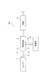
図1は、本発明の第一の実施形態に係る排熱回収装置の構成図、図2は、図1のA−A線断面図、図3は、発電部の断面図である。 1 is a configuration diagram of the exhaust heat recovery apparatus according to the first embodiment of the present invention, FIG. 2 is a cross-sectional view taken along line AA of FIG. 1, and FIG. 3 is a cross-sectional view of a power generation unit.
図1に示すように、本実施形態に係る排熱回収装置M1は、熱源となる内燃機関であるエンジン1および図示しないマフラーに接続された排気管2を備えている。排気管2には、エンジン1から排出される排気ガスが流通する。排気管2には、熱回収部3および触媒4が設けられており、熱回収部3および触媒4は、排気ガスの流れ方向上流側からこの順で配置されている。また、熱回収部3には、ヒートパイプ5の一端側が接続されており、ヒートパイプ5の他端側には、発電部6が接続されている。
As shown in FIG. 1, the exhaust heat recovery apparatus M1 according to this embodiment includes an engine 1 that is an internal combustion engine that serves as a heat source, and an
熱回収部3は、図2に示すように、筐体10を備えている。筐体10の中央部には、排気ガス流路11が形成されており、排気ガス流路11は、6本の支持部材12によって6個の区画に分割されている。また、筐体10の内側には、排気ガス流路11方向に突出する熱回収用フィン13が設けられており、排気ガス流路11を流れる排気ガスに含まれる熱を吸熱する。
As shown in FIG. 2, the
さらに、筐体10の外周部には、ヒートパイプ5が取り付けられている。ヒートパイプ5は、筐体10に対して、ヒートパイプ取付部材14をボルト15で締め付けることによって筐体10に取り付けられている。ヒートパイプ5は、排気ガス流路11の半周を取り囲むように、2本のヒートパイプ5が配置されている。このヒートパイプ5は、排気ガスの流れ方向に離間して、複数設けられている。
Further, a
触媒4としてはいわゆる三元触媒が用いられており、排気ガス中に含まれる窒素酸化物、一酸化炭素、および炭化水素などの物質を浄化している。この触媒4は、図示しないケースに収容されており、このケース内を流通した排気ガスが触媒4によって浄化される。触媒4の活性化温度は、触媒4の原料等によって異なるが、たとえば300℃〜400℃の範囲内の温度となる。 A so-called three-way catalyst is used as the catalyst 4 to purify substances such as nitrogen oxides, carbon monoxide, and hydrocarbons contained in the exhaust gas. The catalyst 4 is accommodated in a case (not shown), and the exhaust gas flowing through the case is purified by the catalyst 4. The activation temperature of the catalyst 4 varies depending on the raw material of the catalyst 4 and the like, but is, for example, a temperature within a range of 300 ° C to 400 ° C.
また、ヒートパイプ5は、一端部が熱回収部3に接続され、他端部が発電部6に接続されており、内部に熱媒体が収容されている。熱媒体としては、作動開始温度が触媒活性化温度よりも高い温度のものが用いられ、触媒4の活性化温度よりも高い温度で熱回収部3から発電部6への熱の輸送が行われる。ヒートパイプ5の作動開始温度は、熱媒体の種類および内部圧力などによって設定することができ、たとえば熱媒体としてセシウムを用いた場合には450℃〜900℃、カリウムを用いた場合には500℃〜1000℃、ナトリウムを用いた場合には600℃〜1200℃とすることができる。
The
発電部6には、図3に示すように、複数の熱電変換モジュール16およびこれらの熱電変換モジュール16に対応するモジュール冷却部17が設けられている。複数の熱電変換モジュール16は、ヒートパイプ5の他端部に接触した状態で、ヒートパイプ5の長手方向に離間して配置されている。この熱電変換モジュール16は、いわゆるゼーベック効果を利用して熱エネルギーを電気エネルギーに変換する素子である。
As shown in FIG. 3, the
モジュール冷却部17は、熱電変換モジュール16におけるヒートパイプ5と接触している一面側の反対側の他面側に接触して配置されている。モジュール冷却部17には冷却水流路17Aが形成されており、図示しない冷却水流通管と接続されている。この冷却水流路17Aに冷却水流通管から冷却水が循環供給されることにより、熱電変換モジュールの他面側が冷却される。
The
また、熱電変換モジュール16の一面側は、ヒートパイプ5によって熱回収部3移動させられた熱によって加温されている。こうして、熱電変換モジュール16の一面側と他面側との間で温度差が生じて、熱電変換モジュール16における熱電変換による発電が行われる。
In addition, one surface side of the
モジュール冷却部17における熱電変換モジュール16と接触する面の反対側の面には、皿バネ18が設けられている。この皿バネ18の付勢力によって、モジュール冷却部17が熱電変換モジュール16に押し付けられ、モジュール冷却部17によって熱電変換モジュール16の他面側が冷却される。
A
以上の構成を有する本実施形態に係る排熱回収装置の動作、作用について説明する。 The operation and action of the exhaust heat recovery apparatus according to the present embodiment having the above configuration will be described.
本実施形態に係る排熱回収装置M1では、エンジン1が運転を始めると、エンジン1からは排気管2に向けて排気ガスが排出される。エンジン1から排出された排気ガスは、排気管2を流れ、熱回収部3および触媒4を通過して、図示しないマフラーから車外に排出される。
In the exhaust heat recovery apparatus M <b> 1 according to the present embodiment, when the engine 1 starts operation, exhaust gas is discharged from the engine 1 toward the
排気管2を流れ、熱回収部3に流入した排気ガスは、熱回収部3における排気ガス流路11を流れる。このとき、ヒートパイプ5が作動すると、排気ガス流路11を流れる排気ガスからは、熱回収用フィン13によって熱が回収される。熱回収部3は、触媒4よりも排気ガスの流れ方向上流側に配置されている。このため、ヒートパイプ5が作動することにより、排気ガスに含まれる熱が触媒4に奪われることなく、発電部6における熱電変換モジュール16に輸送することができる。したがって、熱電変換モジュール16の発電量を多くすることができる。
The exhaust gas flowing through the
ここで、本実施形態においてヒートパイプ5は、その作動開始温度が触媒4の活性化温度よりも高い温度とされている。触媒4は、活性化温度以上の温度とならないと十分な浄化性能を発揮することができない。このため、エンジン1の始動時など、触媒4の暖機が十分でないときには、排気ガスの熱は熱電変換モジュール16による発電に用いることなく、触媒4の暖機に利用することが好適となる。
Here, in the present embodiment, the operation start temperature of the
この点、本実施形態に係る排熱回収装置M1では、排気管2に熱電変換モジュール16が取り付けられてはいないので、熱電変換モジュール16に熱が逃げることはない。また、熱回収部3に取り付けられたヒートパイプ5の作動開始温度は触媒活性化温度より高い温度に設定されている。触媒4の暖機が済んでいない状態では、通常、エンジン1も暖機されておらず、エンジン1から排出される排気ガスの温度も低くなっている。
In this respect, in the exhaust heat recovery apparatus M1 according to the present embodiment, since the
このように、排気ガスの温度が低く、触媒活性化温度以下となっているときには、ヒートパイプ5が作動せず、熱回収部3における熱の回収が行われない。したがって、エンジン1から排出される排気ガスに含まれる熱を触媒4に伝熱することができるので、触媒4の暖機を早期に行うことができる。
As described above, when the temperature of the exhaust gas is low and is equal to or lower than the catalyst activation temperature, the
また、触媒4およびエンジン1の暖機が済み、排気ガスの温度が高く、触媒活性化温度を超える温度となったときには、ヒートパイプ5の作動が行われる。このときには、熱回収部3における熱回収用フィン13で回収された排気ガスの熱がヒートパイプ5を通じて熱電変換モジュール16の一面側に移動させられる。
Further, when the catalyst 4 and the engine 1 are warmed up and the temperature of the exhaust gas is high and exceeds the catalyst activation temperature, the operation of the
さらに、熱電変換モジュール16の他面側では、モジュール冷却部17に冷却水が循環供給される。こうして、熱電変換モジュール16における一面側と他面側との間で温度差が生じ、熱電変換モジュール16による発電が行われる。
Further, on the other side of the
このように、本実施形態に係る排熱回収装置M1では、排気管2に熱回収部3を取り付け、熱回収部3で回収した熱を、ヒートパイプ5を介して熱電変換モジュール16に輸送している。熱回収部3は、触媒4よりも排気ガスの流れ方向上流側に配置されているので、触媒4の暖機が済んだ後は、排気ガスに含まれる熱を触媒4に奪われることなく、熱電変換モジュール16に移動させることができる。したがって、熱電変換モジュール16における発電量を多くすることができる。
As described above, in the exhaust heat recovery apparatus M1 according to this embodiment, the
さらに、本実施形態に係る排熱回収装置M1では、ヒートパイプの作動開始温度を適宜設定することにより、排気ガスに含まれる熱を触媒4と熱電変換モジュール16のいずれに移動するかを変更している。このため、制御装置やON−OFF切り替え手段、さらには触媒4の温度を検出する温度センサを用いる必要がないので、その分装置の簡素化を図ることができる。
Further, in the exhaust heat recovery apparatus M1 according to the present embodiment, by appropriately setting the operation start temperature of the heat pipe, the heat contained in the exhaust gas is changed to either the catalyst 4 or the
次に、本発明の第二の実施形態について説明する。図4は、第二の実施形態に係る排熱回収装置の構成図、図5は、図4のB−B線断面図である。 Next, a second embodiment of the present invention will be described. FIG. 4 is a configuration diagram of the exhaust heat recovery apparatus according to the second embodiment, and FIG. 5 is a cross-sectional view taken along line BB in FIG.
図4に示すように、本実施形態に係る排熱回収装置M2は、エンジン1および図示しないマフラーに接続された排気管2を備えている。排気管2には、エンジン1から排出される排気ガスが流通する。排気管2には、触媒20が設けられている。触媒20には、ヒートパイプ5の一端側が接続されており、ヒートパイプ5の他端側には発電部6が接続されている。
As shown in FIG. 4, the exhaust heat recovery apparatus M2 according to the present embodiment includes an
触媒20は、図5に示すように、ケース21を有している。ケース21の中央部には、排気管2と接続される排気ガス流路22が形成されており、排気ガス流路22には、ケース21に取り付けられた触媒本体23が配設されている。触媒本体23としては、上記第一の実施形態と同様のいわゆる三元触媒が用いられており、排気ガス中に含まれる窒素酸化物、一酸化炭素、および炭化水素などの物質を浄化している。
The
さらに、ケース21の外周部には、ヒートパイプ5が取り付けられている。ヒートパイプ5は、ケース21に対して、ヒートパイプ取付部材24をボルト25で締め付けることによってケース21に取り付けられている。ヒートパイプ5は、排気ガス流路22の半周を取り囲むように、2本のヒートパイプ5が配置されている。このヒートパイプ5は、排気ガスの流れ方向に離間して、複数設けられている。排気ガス流路22を流れる排気ガスの熱は、触媒本体23を通じてケース21に伝熱される。ケース21に伝熱された熱は、ヒートパイプ5を介して発電部6へと伝熱される。
Further, a
ヒートパイプ5の作動開始温度は、触媒本体23の活性化温度とほぼ同等の温度となるように設定されている。また、発電部6は、図3に示す上記第一の実施形態と同様の構成を有しており、熱電変換モジュール16およびモジュール冷却部17等が設けられている。
The operation start temperature of the
以上の構成を有する本実施形態に係る排熱回収装置の動作、作用について説明する。 The operation and action of the exhaust heat recovery apparatus according to the present embodiment having the above configuration will be described.
本実施形態に係る排熱回収装置M2では、エンジン1が運転を始めると、エンジン1からは排気管2に排気ガスが排出される。エンジン1から排出された排気ガスは、排気管2を流れ、触媒20を通過して図示しないマフラーから排出される。
In the exhaust heat recovery apparatus M2 according to this embodiment, when the engine 1 starts operation, exhaust gas is discharged from the engine 1 to the
排気管2を流れ、触媒20に流入した排気ガスは、触媒20における排気ガス流路22を流れる。排気ガス流路22には、触媒本体23が設けられているので、排気ガス流路22を流れる排気ガスの熱は、触媒本体23に伝熱される。
The exhaust gas flowing through the
また、触媒20には、ヒートパイプ5が接続されている。このヒートパイプ5が作動することにより、触媒本体23に輸送された熱は、ケース21を介してヒートパイプ5に伝達される。さらに、この熱は、ヒートパイプ5によって、熱電変換モジュール16の一面側に輸送される。
A
ここで、ヒートパイプ5の作動開始温度は、触媒本体23の活性化温度とほぼ同等の温度に設定されている。このため、触媒本体23が活性化温度に到達するまでは、ヒートパイプ5は作動せず、排気ガスに含まれる熱は、触媒本体23に伝熱される。触媒本体23は、活性化温度に到達することにより、本来の浄化性能を発揮することができるので、触媒本体23が活性化温度に到達するまでは、排気ガスに含まれる熱が触媒本体23に伝熱されることにより、触媒本体23を早期に暖機することができる。
Here, the operation start temperature of the
触媒本体23が活性化温度に到達した後は、ヒートパイプ5が作動する。ヒートパイプ5が作動することにより、触媒本体23に伝達された熱は、ケース21およびヒートパイプ5を介して発電部6における熱電変換モジュール16に輸送される。したがって、触媒本体23の暖機が済んだ後は、熱電変換モジュール16に多くの熱を移動させることができるので、熱電変換モジュール16における発電量を多くすることができる。
After the
さらに、本実施形態に係る排熱回収装置M2では、ヒートパイプの作動開始温度を適宜設定することにより、排気ガスに含まれる熱を触媒本体23と熱電変換モジュール16のいずれに移動するかを変更している。このため、制御装置やON−OFF切り替え手段、さらには触媒4の温度を検出する温度センサを用いる必要がないので、その分装置の簡素化を図ることができる。
Further, in the exhaust heat recovery apparatus M2 according to the present embodiment, by appropriately setting the operation start temperature of the heat pipe, the heat contained in the exhaust gas is changed to either the
続いて、本発明の第三の実施形態について説明する。図6は、本発明の第三の実施形態に係る排熱回収装置の構成図、図7は、図6のC−C線断面図である。 Subsequently, a third embodiment of the present invention will be described. 6 is a configuration diagram of an exhaust heat recovery apparatus according to the third embodiment of the present invention, and FIG. 7 is a cross-sectional view taken along the line CC of FIG.
図6に示すように、本実施形態に係る排熱回収装置M3は、図4に示すように、本実施形態に係る排熱回収装置M2は、エンジン1および図示しないマフラーに接続された排気管2を備えている。排気管2には、エンジン1から排出される排気ガスが流通する。排気管2には、熱回収部3および触媒4が設けられている。熱回収部3および触媒4は、排気ガスの流れ方向上流側からこの順で配置されている。
As shown in FIG. 6, the exhaust heat recovery device M3 according to the present embodiment includes an exhaust pipe connected to the engine 1 and a muffler (not shown) as shown in FIG. 2 is provided. Exhaust gas discharged from the engine 1 flows through the
熱回収部3には、ヒートパイプ5の一端側が接続されており、ヒートパイプ5の他端側は発電部6に接続されている。さらに、熱回収部3には、第二ヒートパイプ30の一端側が接続されており、第二ヒートパイプ30の他端側は触媒4の外面部に接続されている。ヒートパイプ5は、上記第一の実施形態と同様、その作動開始温度が触媒4の活性化温度より高い温度に設定されている。一方、第二ヒートパイプ30は、その作動開始温度が、触媒4の活性化温度よりも低い温度に設定されている。また、第二ヒートパイプ30の作動温度は、ヒートパイプ5の作動開始温度とほぼ同程度の温度に設定されている。このため、排気ガスの温度がヒートパイプ5の作動温度に到達すると、第二ヒートパイプ30の内部の熱媒体がドライアウトし、熱の輸送ができなくなるように設定されている。
One end side of the
図7に示すように、筐体10に対して、ヒートパイプ取付部材14によって複数のヒートパイプ5および第二ヒートパイプ30が取り付けられている。これらのヒートパイプ5および第二ヒートパイプ30は、排気ガスの流れ方向に沿って離間して交互に配置されている。
As shown in FIG. 7, a plurality of
以上の構成を有する本実施形態に係る排熱回収装置M3では、エンジン1が運転を始めると、エンジン1からは排気管2に向けて排気ガスが排出される。エンジン1から排出された排気ガスは、排気管2を流れ、熱回収部3および触媒4を通過して、図示しないマフラーから車外に排出される。
In the exhaust heat recovery apparatus M3 according to this embodiment having the above configuration, when the engine 1 starts operation, exhaust gas is discharged from the engine 1 toward the
排気管2を流れ、熱回収部3に流入した排気ガスは、熱回収部3における排気ガス流路11を流れる。このとき、排気ガスの温度によって、ヒートパイプ5および第二ヒートパイプ30の作動状況が変わる。エンジン1の暖機が済んでいないときには、排気管2を流れる排気ガスの温度が低い状態にある。エンジン1の暖機が済んでいない状態では、通常、触媒4の暖機も済んでいない。排気管2を流れる排気ガスの温度が低く、触媒4の活性化温度以下となっているときには、ヒートパイプ5は作動せず、第二ヒートパイプ30が作動する。
The exhaust gas flowing through the
第二ヒートパイプ30が作動すると、図8(a)に示すように、熱回収部3における熱回収用フィン13で回収された排気ガスの熱は、触媒4の外面へと輸送され、発電部6へは輸送されない。このように、熱回収部3で回収された熱が触媒4へと輸送されることにより、触媒4は外側から暖機される。また、触媒4には、熱回収部3である程度の熱は回収されているが、いまだ熱が残る排気ガスが流れるので、触媒4は内側からも暖機される。このように、触媒4を外側と内側との両方から暖機することにより、触媒4を早期に暖機することができる。
When the
また、エンジン1の暖機が済んだ後は、排気管2には高温の排気ガスが流れる。エンジン1の暖機が済んでいれば、通常、触媒4の暖機も済んでいる。排気管2を流れる排気ガスの温度が高く、触媒4の活性化温度よりも高い温度となっているときには、ヒートパイプ5が作動する。一方、第二ヒートパイプ30では熱媒体がドライアウトするので、熱の輸送は行われず、第二ヒートパイプ30は作動しない。
Further, after the engine 1 has been warmed up, high-temperature exhaust gas flows through the
ヒートパイプ5が作動すると、図8(b)に示すように、熱回収部3における熱回収用フィン13で回収された排気ガスの熱は、発電部6における熱電変換モジュール16の一面側に輸送され、触媒4には輸送されない。
When the
このように、2個の作動開始温度の異なるヒートパイプ5,30を用いることにより、排気ガスの温度、ひいてはエンジン1や触媒4の暖機状態に応じて、熱回収部3で回収された熱の輸送先を変更することができる。そして、排気ガスの温度が触媒4の活性化温度以下となっているときには、熱回収部3で回収した熱を触媒4に輸送し、排気ガスの温度が触媒4の活性化温度よりも高くなっているときには、熱回収部3で回収した熱を発電部6における熱電変換モジュール16の一面側に輸送している。
As described above, by using the two
したがって、触媒4の暖機が済んでいないときには、触媒4の多くの熱を輸送することができるので、触媒4の暖機を早期に行うことができる。また、触媒4の暖機が済んだ後は、多くの熱を熱電変換モジュール16に輸送することができるので、その分発電量を多くすることができる。
Therefore, when the catalyst 4 is not warmed up, much heat of the catalyst 4 can be transported, so that the catalyst 4 can be warmed up early. In addition, after the catalyst 4 has been warmed up, a large amount of heat can be transported to the
さらに、本実施形態に係る排熱回収装置M3では、作動開始温度の異なる2個のヒートパイプ用いることにより、排気ガスに含まれる熱を触媒4と熱電変換モジュール16のいずれに移動するかを変更している。このため、制御装置やON−OFF切り替え手段、さらには触媒4の温度を検出する温度センサを用いる必要がないので、その分装置の簡素化を図ることができる。
Furthermore, in the exhaust heat recovery apparatus M3 according to the present embodiment, by using two heat pipes having different operation start temperatures, it is changed whether the heat contained in the exhaust gas is transferred to the catalyst 4 or the
続いて、本発明の第四の実施形態について説明する。図9は、本発明の第四の実施形態に係る排熱回収装置の構成図である。 Subsequently, a fourth embodiment of the present invention will be described. FIG. 9 is a configuration diagram of an exhaust heat recovery apparatus according to the fourth embodiment of the present invention.
図9に示すように、本実施形態に係る排熱回収装置M4は、エンジン1および図示しないマフラーに接続された排気管2を備えている。排気管2には、エンジン1から排出される排気ガスが流通する。排気管2には、触媒4および熱回収部3が設けられている。触媒4および熱回収部3は、排気ガスの流れ方向上流側からこの順で配置されている。
As shown in FIG. 9, the exhaust heat recovery apparatus M4 according to this embodiment includes an
熱回収部3には、ヒートパイプ5の一端部が接続され、ヒートパイプ5の他端部が触媒4に接続されている。ヒートパイプ50の作動開始温度は、触媒4の活性化温度を中心として、広い範囲となるように設定されている。
One end of the
以上の構成を有する本実施形態に係る排熱回収装置M4では、エンジン1が運転を始めると、エンジン1からは排気管2に排気ガスが排出される。エンジン1から排出された排気ガスは、排気管2を流れ、触媒4および熱回収部3を通過して図示しないマフラーから排出される。
In the exhaust heat recovery apparatus M4 according to this embodiment having the above configuration, exhaust gas is discharged from the engine 1 to the
排気管2を流れ、触媒4に流入した排気ガスは、エンジン1および触媒4の暖機が済んでいないときには、触媒4を暖機して下流側に排出される。ここで、触媒4では、排気ガスの熱が回収されるものの、排気ガス中に含まれる熱を完全に伝達することができない。これに対して、本実施形態に係る排熱回収装置M4では、触媒4の下流側に熱回収部3が設けられている。
When the engine 1 and the catalyst 4 are not warmed up, the exhaust gas flowing through the
触媒4から排出された排気ガス中には、いまだ熱が含まれているが、触媒4の下流側に設けられた熱回収部3によって、排気ガス中に残存する熱を回収する。熱回収部3と触媒4との間には、ヒートパイプ5が設けられている。このため、熱回収部3で回収した熱を触媒4に輸送することができる。こうして、触媒4で回収し切れなかった排気ガス中の熱を熱回収部3で回収して、ヒートパイプ5を介して触媒4に輸送することにより、触媒4を早期に暖機することができる。
The exhaust gas exhausted from the catalyst 4 still contains heat, but the heat remaining in the exhaust gas is recovered by the
また、エンジン1および触媒4の暖機が済んだ後は、排気管2には熱を多く含む排気ガスが流入する。このときには、触媒4の暖機も済んでおり、触媒4は外部と内部との温度差がほとんどなくなっている。熱を多く含む排気ガスは、排気管2から触媒4に流入する。ところが、このときには触媒4の暖機も済んでいるので、多量の熱が触媒4に輸送されると、触媒4の高温劣化を誘発する原因となる。
Further, after the engine 1 and the catalyst 4 are warmed up, exhaust gas containing a large amount of heat flows into the
この点、本実施形態に係る排熱回収装置M4では触媒4と熱回収部3との間にヒートパイプ5が設けられている。また、触媒4は内部と外部との温度差がなくなっていることから、触媒4は、熱回収部3よりも高温となっている。このため、ヒートパイプ5により、触媒4に輸送された余剰の熱を熱回収部3に輸送することができる。このようにして、余剰の熱を熱回収部3に輸送することにより、触媒4の高温劣化を防止することができる。
In this regard, in the exhaust heat recovery apparatus M4 according to the present embodiment, a
また、上記第四の実施形態では、熱電変換モジュールを設けていないが、たとえば熱電変換モジュールを、排気管2における熱回収部3よりも排気ガスの流れ方向下流側に配置して設ける態様とすることもできる。
In the fourth embodiment, the thermoelectric conversion module is not provided. However, for example, the thermoelectric conversion module is disposed and provided downstream of the
この態様では、触媒4の暖機が済むまでは、熱電変換モジュールによる発電は行われないので、触媒4の暖機を早期に行うことの妨げとはならないようにすることができる。さらに、触媒4の暖機が済んだ後は、触媒4からヒートパイプ5を介して熱回収部3に輸送された熱を熱電変換モジュールによる発電に利用することができる。また、熱回収部3に対して、触媒4の活性化温度よりも高い作動開始温度のヒートパイプを介して熱電変換モジュールを接続することによっても、同様の作用効果を得ることができる。
In this aspect, power generation by the thermoelectric conversion module is not performed until the catalyst 4 is warmed up, so that it is possible to prevent the catalyst 4 from warming up early. Furthermore, after the catalyst 4 has been warmed up, the heat transported from the catalyst 4 to the
次に、本発明の第五の実施形態について説明する。図10は、(a)、(b)とも、本発明の第五の実施形態に係る排熱回収装置の構成図である。 Next, a fifth embodiment of the present invention will be described. FIGS. 10A and 10B are configuration diagrams of an exhaust heat recovery apparatus according to the fifth embodiment of the present invention.
図10(a)に示すように、本実施形態に係る排熱回収装置M5は、エンジン1および図示しないマフラーに接続された排気管2を備えている。排気管2には、エンジン1から排出される排気ガスが流通する。排気管2には、熱回収部3および触媒4が設けられている。これらの熱回収部3および触媒4は、排気ガスの流れ方向上流側からこの順で配置されている。
As shown in FIG. 10A, the exhaust heat recovery apparatus M5 according to this embodiment includes an
熱回収部3には、ヒートパイプ50の一端側が接続されており、ヒートパイプ50の他端側は発電部6に接続されている。また、ヒートパイプ50は、触媒4を通過するようにして配置されている。ヒートパイプ50の作動開始温度は、触媒4の活性化温度以下の温度であり、触媒4の活性化温度より高い温度では、触媒4における熱媒体の液化が不能となり、触媒4への熱輸送が不能となるように設定されている。
One end side of the
以上の構成を有する本実施形態に係る排熱回収装置M5においては、エンジン1が運転を始めると、エンジン1からは排気管2に排気ガスが排出される。エンジン1から排出された排気ガスは、排気管2を流れ、熱回収部3および触媒4を通過して図示しないマフラーから排出される。
In the exhaust heat recovery apparatus M5 according to this embodiment having the above configuration, exhaust gas is discharged from the engine 1 to the
排気管2を流れ、熱回収部3に流入した排気ガスは、熱回収部3において排気ガスに含まれる熱の回収が行われる。熱回収部3で回収された熱は、ヒートパイプ5を介して触媒4および発電部6へと輸送される。ヒートパイプ5によって触媒4に輸送された熱は、触媒4の温度が活性化温度に到達する前では、触媒4へと輸送される。触媒4では、ヒートパイプ5によって熱回収部3から輸送された熱により、暖機が促進される。こうして、触媒4の暖機を早めることができる。
The exhaust gas flowing through the
また、エンジン1および触媒4の暖機が済み、排気ガスの温度が高くなった後は、ヒートパイプ5の熱媒体は、触媒4における液化が不能な状態となっている。したがって、熱回収部3で回収された熱が触媒4を通過して、発電部6にへと輸送され、熱媒体は発電部6で液化する。こうして、発電部6に熱が輸送され、この熱が発電部6における熱電変換モジュール16の一面側に伝熱されることにより、熱電変換モジュール16における発電効率を向上させる。
Further, after the engine 1 and the catalyst 4 have been warmed up and the temperature of the exhaust gas has risen, the heat medium of the
このように、本実施形態に係る排熱回収装置M5では、触媒4の暖機が済むまでは、熱回収部3で回収された熱が触媒4に輸送され、触媒4の暖機が済んだ後は、熱電変換モジュール16へと輸送される。したがって、触媒4の暖機を早めるとともに、熱電変換モジュール16による発電効率を高めることができる。
Thus, in the exhaust heat recovery apparatus M5 according to the present embodiment, the heat recovered by the
さらに、本実施形態では、触媒4よりも排気ガスの流れ方向上流側に熱回収部3を設けているが、図10(b)に示すように、触媒4よりも排気ガスの流れ方向下流側に熱回収部3を設ける態様とすることもできる。この態様では、発電部6用と触媒4の暖機用との熱回収部を別個に設けることなく、一体的に設けることができる。
Furthermore, in the present embodiment, the
1…エンジン、2…排気管、3…熱回収部、4,20…触媒、5,30,50…ヒートパイプ、6…発電部、10…筐体、11…排気ガス流路、12…支持部材、13…熱回収用フィン、14…ヒートパイプ取付部材、15…ボルト、16…熱電変換モジュール、17…モジュール冷却部、17A…冷却水流路、18…皿バネ、21…ケース、22…排気ガス流路、23…触媒本体、24…ヒートパイプ取付部材、25…ボルト、50…ヒートパイプ、M1〜M5…排熱回収装置。 DESCRIPTION OF SYMBOLS 1 ... Engine, 2 ... Exhaust pipe, 3 ... Heat recovery part, 4,20 ... Catalyst, 5, 30, 50 ... Heat pipe, 6 ... Power generation part, 10 ... Housing, 11 ... Exhaust gas flow path, 12 ... Support Members, 13 ... heat recovery fins, 14 ... heat pipe mounting members, 15 ... bolts, 16 ... thermoelectric conversion module, 17 ... module cooling section, 17A ... cooling water flow path, 18 ... disc spring, 21 ... case, 22 ... exhaust Gas flow path, 23 ... catalyst body, 24 ... heat pipe mounting member, 25 ... bolt, 50 ... heat pipe, M1 to M5 ... exhaust heat recovery device.
Claims (5)
熱電交換による発電を行う熱電変換素子と、
前記熱回収部と前記熱電変換素子との間に取り付けられ、前記熱回収部の熱を前記熱電変換素子に伝熱するヒートパイプと、
を備え、
前記ヒートパイプの作動開始温度は、前記触媒の活性化温度よりも高い温度に設定されていることを特徴とする排熱回収装置。 A heat recovery part attached to an exhaust pipe provided with a catalyst for purifying the exhaust gas while exhaust gas discharged from the internal combustion engine flows;
A thermoelectric conversion element for generating electricity by thermoelectric exchange;
A heat pipe that is attached between the heat recovery unit and the thermoelectric conversion element, and transfers heat of the heat recovery unit to the thermoelectric conversion element;
With
The exhaust heat recovery apparatus according to claim 1, wherein an operation start temperature of the heat pipe is set to a temperature higher than an activation temperature of the catalyst.
前記第二ヒートパイプの作動開始温度は、前記触媒の活性化温度以下の温度に設定されている請求項1に記載の排熱回収装置。 A second heat pipe attached between the heat recovery unit and the catalyst, and transferring heat of the heat recovery unit to the catalyst;
The exhaust heat recovery apparatus according to claim 1, wherein an operation start temperature of the second heat pipe is set to a temperature equal to or lower than an activation temperature of the catalyst.
内燃機関から排出される排気ガスが流通するとともに前記排気ガスを浄化する触媒と前記熱電変換素子との間に取り付けられ、前記触媒の熱を前記熱電変換素子に伝熱するヒートパイプと、
を備え、
前記ヒートパイプの作動開始温度は、前記触媒の活性化温度と同等の温度に設定されていることを特徴とする排熱回収装置。 A thermoelectric conversion element for generating electricity by thermoelectric exchange;
A heat pipe through which exhaust gas discharged from an internal combustion engine flows and is attached between the catalyst for purifying the exhaust gas and the thermoelectric conversion element, and transfers heat of the catalyst to the thermoelectric conversion element;
With
The exhaust heat recovery apparatus according to claim 1, wherein an operation start temperature of the heat pipe is set to a temperature equivalent to an activation temperature of the catalyst.
熱電交換による発電を行う熱電変換素子と、
前記熱回収部と前記触媒との間に取り付けられ、前記熱回収部の熱を前記触媒に伝熱するヒートパイプと、
を備え、
前記ヒートパイプの作動開始温度は、前記触媒の活性化温度以下の温度に設定されていることを特徴とする排熱回収装置。 An exhaust gas exhausted from the internal combustion engine circulates, and a heat recovery unit attached to an exhaust pipe provided with a catalyst for purifying the exhaust gas,
A thermoelectric conversion element for generating electricity by thermoelectric exchange;
A heat pipe attached between the heat recovery unit and the catalyst and transferring heat of the heat recovery unit to the catalyst;
With
The exhaust heat recovery apparatus according to claim 1, wherein an operation start temperature of the heat pipe is set to a temperature equal to or lower than an activation temperature of the catalyst.
熱電交換による発電を行う熱電変換素子と、
前記熱回収部、前記触媒、および前記熱電変換素子の間に取り付けられ、前記熱回収部の熱を前記触媒および前記熱電変換素子に伝熱するヒートパイプと、
を備え、
前記ヒートパイプの作動開始温度は、前記触媒の活性化温度以下の温度に設定されており、
前記熱回収部で回収した熱を前記触媒に輸送し、その後前記熱電変換素子に輸送することを特徴とする排熱回収装置。 An exhaust gas exhausted from the internal combustion engine circulates, and a heat recovery unit attached to an exhaust pipe provided with a catalyst for purifying the exhaust gas,
A thermoelectric conversion element for generating electricity by thermoelectric exchange;
A heat pipe attached between the heat recovery unit, the catalyst, and the thermoelectric conversion element, and transferring heat of the heat recovery unit to the catalyst and the thermoelectric conversion element;
With
The operation start temperature of the heat pipe is set to a temperature below the activation temperature of the catalyst,
The exhaust heat recovery apparatus, wherein the heat recovered by the heat recovery unit is transported to the catalyst and then transported to the thermoelectric conversion element.
Priority Applications (4)
| Application Number | Priority Date | Filing Date | Title |
|---|---|---|---|
| JP2004083049A JP4085998B2 (en) | 2004-03-22 | 2004-03-22 | Waste heat recovery device |
| US11/075,940 US7178332B2 (en) | 2004-03-22 | 2005-03-10 | Exhaust heat recovery system |
| DE102005013330A DE102005013330B4 (en) | 2004-03-22 | 2005-03-22 | heat recovery system |
| CN2005100559613A CN1673497B (en) | 2004-03-22 | 2005-03-22 | Exhaust heat recovery system |
Applications Claiming Priority (1)
| Application Number | Priority Date | Filing Date | Title |
|---|---|---|---|
| JP2004083049A JP4085998B2 (en) | 2004-03-22 | 2004-03-22 | Waste heat recovery device |
Publications (2)
| Publication Number | Publication Date |
|---|---|
| JP2005264916A JP2005264916A (en) | 2005-09-29 |
| JP4085998B2 true JP4085998B2 (en) | 2008-05-14 |
Family
ID=34984706
Family Applications (1)
| Application Number | Title | Priority Date | Filing Date |
|---|---|---|---|
| JP2004083049A Expired - Fee Related JP4085998B2 (en) | 2004-03-22 | 2004-03-22 | Waste heat recovery device |
Country Status (4)
| Country | Link |
|---|---|
| US (1) | US7178332B2 (en) |
| JP (1) | JP4085998B2 (en) |
| CN (1) | CN1673497B (en) |
| DE (1) | DE102005013330B4 (en) |
Families Citing this family (51)
| Publication number | Priority date | Publication date | Assignee | Title |
|---|---|---|---|---|
| JP4165405B2 (en) * | 2003-10-06 | 2008-10-15 | トヨタ自動車株式会社 | Exhaust gas purification device |
| JP4055728B2 (en) * | 2004-03-19 | 2008-03-05 | トヨタ自動車株式会社 | Waste heat recovery device |
| US7253353B2 (en) * | 2004-06-30 | 2007-08-07 | General Motors Corporation | Thermoelectric augmented hybrid electric propulsion system |
| JP4479488B2 (en) * | 2004-12-01 | 2010-06-09 | 株式会社デンソー | Exhaust power generator |
| US7610993B2 (en) * | 2005-08-26 | 2009-11-03 | John Timothy Sullivan | Flow-through mufflers with optional thermo-electric, sound cancellation, and tuning capabilities |
| US7600375B2 (en) * | 2006-02-14 | 2009-10-13 | Ford Global Technologies, Llc | Catalytic device with fuel cell portion and catalytic conversion portion |
| US7915516B2 (en) * | 2006-05-10 | 2011-03-29 | The Boeing Company | Thermoelectric power generator with built-in temperature adjustment |
| GB0618867D0 (en) * | 2006-09-25 | 2006-11-01 | Univ Sussex The | Vehicle power supply system |
| US7808214B2 (en) | 2006-12-19 | 2010-10-05 | Bradley Wayne Bartilson | Short-cycling serial hybrid drivetrain with high power density storage |
| US8556009B2 (en) * | 2006-12-19 | 2013-10-15 | Bradley Wayne Bartilson | Safe, super-efficient, four-wheeled vehicle employing large diameter wheels with continuous-radius tires, with leaning option |
| US8100216B2 (en) * | 2006-12-19 | 2012-01-24 | Bradley Wayne Bartilson | Hybrid drivetrain with waste heat energy conversion into electricity |
| JP5128866B2 (en) * | 2007-07-10 | 2013-01-23 | 株式会社アツミテック | Vehicle propulsion device |
| US7797938B2 (en) * | 2007-07-31 | 2010-09-21 | Caterpillar Inc | Energy recovery system |
| JP2009051386A (en) * | 2007-08-28 | 2009-03-12 | Fujikura Ltd | Apparatus and method for remaining heat utilization power generation for automobile |
| DE102008005334A1 (en) * | 2008-01-21 | 2009-07-30 | Christian Vitek | Thermoelectric generator for exhaust gas stream, is attached at waste gas flue, and thermoelectric transducer element is arranged, which converts thermal energy into electricity |
| JP5289819B2 (en) * | 2008-05-14 | 2013-09-11 | トヨタ自動車株式会社 | Heat exchanger and thermoelectric generator |
| JP4656193B2 (en) * | 2008-06-17 | 2011-03-23 | 株式会社デンソー | Catalyst warm-up controller |
| US8341950B2 (en) * | 2008-07-18 | 2013-01-01 | Ford Global Technologies, Llc | Engine exhaust system having a thermoelectric conversion device and a heat pipe |
| US8793992B2 (en) * | 2008-07-28 | 2014-08-05 | Spansion Llc | Thermoelectric device for use with Stirling engine |
| JP2010059960A (en) * | 2008-08-08 | 2010-03-18 | Toyota Motor Corp | Exhaust heat recovery device |
| WO2010026662A1 (en) * | 2008-09-08 | 2010-03-11 | トヨタ自動車 株式会社 | Vehicular control device |
| JP5195381B2 (en) * | 2008-12-11 | 2013-05-08 | 株式会社デンソー | Exhaust heat recovery device |
| DE102008063487A1 (en) * | 2008-12-17 | 2010-06-24 | Emitec Gesellschaft Für Emissionstechnologie Mbh | Device for generating electrical energy from an exhaust gas |
| US20100154394A1 (en) * | 2008-12-22 | 2010-06-24 | Exxonmobil Research And Engineering Company | Exhaust heat recovery system |
| WO2010112958A1 (en) * | 2009-03-30 | 2010-10-07 | Renault Trucks | Internal combustion engine arrangement comprising a particulate filter and a thermoelectric device |
| US8552283B2 (en) * | 2010-01-11 | 2013-10-08 | Toyota Motor Engineering & Manufacturing North America, Inc. | Thermoelectric application for waste heat recovery from semiconductor devices in power electronics systems |
| DE102010001417A1 (en) * | 2010-02-01 | 2011-08-04 | Robert Bosch GmbH, 70469 | Heat exchanger for thermoelectric generators |
| DE102010042271A1 (en) * | 2010-10-11 | 2012-04-12 | Robert Bosch Gmbh | Method for temperature management of emission control system in exhaust duct of internal combustion engine, involves including operation modes of thermoelectric generators in temperature management of emission control system |
| SE535355C2 (en) * | 2010-11-08 | 2012-07-03 | Scania Cv Ab | Exhaust after-treatment device and process for after-treatment of exhaust gases |
| FR2968714B1 (en) * | 2010-12-08 | 2015-04-10 | IFP Energies Nouvelles | METHOD AND DEVICE FOR CONTROLLING THE EXHAUST GAS TEMPERATURE OF AN INTERNAL COMBUSTION ENGINE CROSSING A MEANS FOR TREATING THE POLLUTANTS CONTAINED IN THESE GASES |
| DE102010054640A1 (en) * | 2010-12-15 | 2012-06-21 | Benteler Automobiltechnik Gmbh | heat exchangers |
| JP6181560B2 (en) * | 2011-03-18 | 2017-08-16 | ビーエーエスエフ ソシエタス・ヨーロピアBasf Se | Exhaust train with integrated thermoelectric generator |
| CN103256581A (en) * | 2013-05-03 | 2013-08-21 | 福建工程学院 | Heat dissipation system for LED headlamp of motor vehicle |
| TWI527959B (en) * | 2014-08-20 | 2016-04-01 | 財團法人工業技術研究院 | Waste heat exchanger |
| KR20160063000A (en) * | 2014-11-26 | 2016-06-03 | 현대자동차주식회사 | Thermoelectric generation device |
| US10018079B2 (en) * | 2015-01-23 | 2018-07-10 | Ford Global Technologies, Llc | Thermodynamic system in a vehicle |
| EP3165735B1 (en) * | 2015-11-06 | 2018-05-23 | C.R.F. Società Consortile per Azioni | A unit for conversion of thermal energy |
| CN105383321A (en) * | 2015-12-10 | 2016-03-09 | 上海电机学院 | Vehicle night driving safety warning system |
| WO2017163256A1 (en) * | 2016-03-21 | 2017-09-28 | Abhishek Singh | Automotive temperature and pollutant regulating module |
| US10174659B2 (en) | 2016-07-08 | 2019-01-08 | Toyota Manufacturing Engineering & Manufacturing North America, Inc. | Switchable radiative energy harvesting systems |
| JP6354811B2 (en) * | 2016-09-01 | 2018-07-11 | マツダ株式会社 | Engine exhaust heat recovery device |
| CN109083722A (en) * | 2017-06-14 | 2018-12-25 | 天纳克(苏州)排放系统有限公司 | Engine exhaust post-processes mixing arrangement and its after-treatment device and application |
| GB2564520B (en) * | 2017-07-10 | 2019-07-17 | Ford Global Tech Llc | A system and method for heating a vehicle catalytic converter |
| GB2564431B (en) * | 2017-07-10 | 2019-07-17 | Ford Global Tech Llc | A system and method for heating a vehicle catalytic converter |
| CN107612425A (en) * | 2017-10-13 | 2018-01-19 | 大连海事大学 | The marine exhaust generation device through temperature difference of waste heat and electricity-generating method of the heat pipe intensified heat exchange of multi-stag |
| KR102406140B1 (en) * | 2017-10-30 | 2022-06-07 | 현대자동차 주식회사 | Exhaust heat recovery apparatus |
| CN108930580B (en) * | 2018-07-24 | 2019-09-17 | 湖州新兴汽车部件有限公司 | A kind of exhaust manifold with heat recovery function |
| KR102598538B1 (en) * | 2018-10-22 | 2023-11-03 | 현대자동차주식회사 | Exhaust tail trim for vehicle |
| DE102019120283B4 (en) * | 2019-07-26 | 2024-05-02 | Deutsches Zentrum für Luft- und Raumfahrt e.V. | Engine system and method for operating an engine system |
| CN111337535A (en) * | 2020-04-02 | 2020-06-26 | 南京航空航天大学 | Heat pipe heat transfer performance testing device and testing method thereof |
| CN111842064A (en) * | 2020-07-08 | 2020-10-30 | 东莞市创明电池技术有限公司 | Lithium battery formation partial volume heat production recycle system |
Family Cites Families (8)
| Publication number | Priority date | Publication date | Assignee | Title |
|---|---|---|---|---|
| DE2441049A1 (en) * | 1974-08-27 | 1976-03-18 | Bosch Gmbh Robert | Engine exhaust purifier with thermal or catalytic reactor - has heat storage element connected with reactor via heat-conducting means |
| IT1182849B (en) * | 1985-09-03 | 1987-10-05 | Ital Idee Srl | THERMOELECTRIC EFFECT EQUIPMENT FOR THE GENERATION OF CURRENT IN ENDOTHERMIC MOTOR VEHICLES AND SIMILAR, WITH HEAT RECOVERY DISSIPATED OUTSIDE |
| JPH0712005A (en) * | 1993-06-23 | 1995-01-17 | Nippondenso Co Ltd | Electronic control device for vehicle |
| JPH10227238A (en) * | 1997-02-13 | 1998-08-25 | Nissan Motor Co Ltd | Electric energy supply device for vehicle |
| US5968456A (en) * | 1997-05-09 | 1999-10-19 | Parise; Ronald J. | Thermoelectric catalytic power generator with preheat |
| JP2003065045A (en) | 2001-08-24 | 2003-03-05 | Toyota Motor Corp | Exhaust heat recovery device |
| WO2004059138A1 (en) | 2002-12-26 | 2004-07-15 | Toyota Jidosha Kabushiki Kaisha | Exhaust heat power generation apparatus |
| JP2005223132A (en) * | 2004-02-05 | 2005-08-18 | Toyota Motor Corp | Thermoelectric generator of internal combustion engine |
-
2004
- 2004-03-22 JP JP2004083049A patent/JP4085998B2/en not_active Expired - Fee Related
-
2005
- 2005-03-10 US US11/075,940 patent/US7178332B2/en not_active Expired - Fee Related
- 2005-03-22 CN CN2005100559613A patent/CN1673497B/en not_active Expired - Fee Related
- 2005-03-22 DE DE102005013330A patent/DE102005013330B4/en not_active Expired - Fee Related
Also Published As
| Publication number | Publication date |
|---|---|
| DE102005013330A1 (en) | 2005-10-20 |
| DE102005013330B4 (en) | 2009-07-30 |
| US20050204733A1 (en) | 2005-09-22 |
| CN1673497B (en) | 2010-07-14 |
| JP2005264916A (en) | 2005-09-29 |
| US7178332B2 (en) | 2007-02-20 |
| CN1673497A (en) | 2005-09-28 |
Similar Documents
| Publication | Publication Date | Title |
|---|---|---|
| JP4085998B2 (en) | Waste heat recovery device | |
| JP4055728B2 (en) | Waste heat recovery device | |
| JP4165405B2 (en) | Exhaust gas purification device | |
| JP2821582B2 (en) | Method and apparatus for thermal management of a vehicle exhaust system | |
| KR100649383B1 (en) | Exhaust system | |
| JP4891318B2 (en) | Thermoelectric generator with intermediate loop | |
| JP6034147B2 (en) | Waste heat recovery device | |
| JP2006214350A (en) | Thermoelectric generator | |
| US20110192141A1 (en) | Exhaust system component having a combination of a heat exchanger and a catalytic converter, motor vehicle having the component and method of operating the component | |
| JP2007016747A (en) | Automobile exhaust heat power generation device | |
| JP5737151B2 (en) | Thermoelectric generator | |
| JPS6368714A (en) | Exhaust emission control device for engine | |
| JP2013099201A (en) | Thermoelectric generator | |
| JP4871844B2 (en) | Waste heat recovery device | |
| JP2004332596A (en) | Thermoelectric generating set | |
| JP2000352313A (en) | Exhaust heat power generation system for automobile | |
| JP2010038072A (en) | Exhaust treatment device for internal combustion engine | |
| JP2007187139A (en) | Exhaust heat recovery system | |
| JP2007032534A (en) | Thermal power generating apparatus | |
| JP2018062909A (en) | Waste heat recovery power generation device | |
| JP2010084546A (en) | Exhaust emission control system and exhaust emission control method | |
| JP4285144B2 (en) | Waste heat energy recovery device | |
| JP2005051952A (en) | Generator | |
| JP2005150653A (en) | Waste heat energy recovery apparatus | |
| JP2004211660A (en) | Exhaust system |
Legal Events
| Date | Code | Title | Description |
|---|---|---|---|
| A977 | Report on retrieval |
Free format text: JAPANESE INTERMEDIATE CODE: A971007 Effective date: 20080118 |
|
| TRDD | Decision of grant or rejection written | ||
| A01 | Written decision to grant a patent or to grant a registration (utility model) |
Free format text: JAPANESE INTERMEDIATE CODE: A01 Effective date: 20080129 |
|
| A61 | First payment of annual fees (during grant procedure) |
Free format text: JAPANESE INTERMEDIATE CODE: A61 Effective date: 20080211 |
|
| FPAY | Renewal fee payment (event date is renewal date of database) |
Free format text: PAYMENT UNTIL: 20110228 Year of fee payment: 3 |
|
| FPAY | Renewal fee payment (event date is renewal date of database) |
Free format text: PAYMENT UNTIL: 20120229 Year of fee payment: 4 |
|
| FPAY | Renewal fee payment (event date is renewal date of database) |
Free format text: PAYMENT UNTIL: 20120229 Year of fee payment: 4 |
|
| FPAY | Renewal fee payment (event date is renewal date of database) |
Free format text: PAYMENT UNTIL: 20130228 Year of fee payment: 5 |
|
| FPAY | Renewal fee payment (event date is renewal date of database) |
Free format text: PAYMENT UNTIL: 20130228 Year of fee payment: 5 |
|
| FPAY | Renewal fee payment (event date is renewal date of database) |
Free format text: PAYMENT UNTIL: 20140228 Year of fee payment: 6 |
|
| LAPS | Cancellation because of no payment of annual fees |