JP2010059960A - Exhaust heat recovery device - Google Patents
Exhaust heat recovery device Download PDFInfo
- Publication number
- JP2010059960A JP2010059960A JP2009148818A JP2009148818A JP2010059960A JP 2010059960 A JP2010059960 A JP 2010059960A JP 2009148818 A JP2009148818 A JP 2009148818A JP 2009148818 A JP2009148818 A JP 2009148818A JP 2010059960 A JP2010059960 A JP 2010059960A
- Authority
- JP
- Japan
- Prior art keywords
- heat
- catalyst
- valve device
- cooling water
- path
- Prior art date
- Legal status (The legal status is an assumption and is not a legal conclusion. Google has not performed a legal analysis and makes no representation as to the accuracy of the status listed.)
- Pending
Links
Images


Classifications
-
- F—MECHANICAL ENGINEERING; LIGHTING; HEATING; WEAPONS; BLASTING
- F01—MACHINES OR ENGINES IN GENERAL; ENGINE PLANTS IN GENERAL; STEAM ENGINES
- F01N—GAS-FLOW SILENCERS OR EXHAUST APPARATUS FOR MACHINES OR ENGINES IN GENERAL; GAS-FLOW SILENCERS OR EXHAUST APPARATUS FOR INTERNAL COMBUSTION ENGINES
- F01N5/00—Exhaust or silencing apparatus combined or associated with devices profiting from exhaust energy
- F01N5/02—Exhaust or silencing apparatus combined or associated with devices profiting from exhaust energy the devices using heat
-
- F—MECHANICAL ENGINEERING; LIGHTING; HEATING; WEAPONS; BLASTING
- F01—MACHINES OR ENGINES IN GENERAL; ENGINE PLANTS IN GENERAL; STEAM ENGINES
- F01N—GAS-FLOW SILENCERS OR EXHAUST APPARATUS FOR MACHINES OR ENGINES IN GENERAL; GAS-FLOW SILENCERS OR EXHAUST APPARATUS FOR INTERNAL COMBUSTION ENGINES
- F01N13/00—Exhaust or silencing apparatus characterised by constructional features ; Exhaust or silencing apparatus, or parts thereof, having pertinent characteristics not provided for in, or of interest apart from, groups F01N1/00 - F01N5/00, F01N9/00, F01N11/00
- F01N13/009—Exhaust or silencing apparatus characterised by constructional features ; Exhaust or silencing apparatus, or parts thereof, having pertinent characteristics not provided for in, or of interest apart from, groups F01N1/00 - F01N5/00, F01N9/00, F01N11/00 having two or more separate purifying devices arranged in series
-
- F—MECHANICAL ENGINEERING; LIGHTING; HEATING; WEAPONS; BLASTING
- F01—MACHINES OR ENGINES IN GENERAL; ENGINE PLANTS IN GENERAL; STEAM ENGINES
- F01P—COOLING OF MACHINES OR ENGINES IN GENERAL; COOLING OF INTERNAL-COMBUSTION ENGINES
- F01P3/00—Liquid cooling
- F01P3/12—Arrangements for cooling other engine or machine parts
-
- F—MECHANICAL ENGINEERING; LIGHTING; HEATING; WEAPONS; BLASTING
- F28—HEAT EXCHANGE IN GENERAL
- F28D—HEAT-EXCHANGE APPARATUS, NOT PROVIDED FOR IN ANOTHER SUBCLASS, IN WHICH THE HEAT-EXCHANGE MEDIA DO NOT COME INTO DIRECT CONTACT
- F28D15/00—Heat-exchange apparatus with the intermediate heat-transfer medium in closed tubes passing into or through the conduit walls ; Heat-exchange apparatus employing intermediate heat-transfer medium or bodies
- F28D15/02—Heat-exchange apparatus with the intermediate heat-transfer medium in closed tubes passing into or through the conduit walls ; Heat-exchange apparatus employing intermediate heat-transfer medium or bodies in which the medium condenses and evaporates, e.g. heat pipes
- F28D15/0266—Heat-exchange apparatus with the intermediate heat-transfer medium in closed tubes passing into or through the conduit walls ; Heat-exchange apparatus employing intermediate heat-transfer medium or bodies in which the medium condenses and evaporates, e.g. heat pipes with separate evaporating and condensing chambers connected by at least one conduit; Loop-type heat pipes; with multiple or common evaporating or condensing chambers
-
- F—MECHANICAL ENGINEERING; LIGHTING; HEATING; WEAPONS; BLASTING
- F28—HEAT EXCHANGE IN GENERAL
- F28D—HEAT-EXCHANGE APPARATUS, NOT PROVIDED FOR IN ANOTHER SUBCLASS, IN WHICH THE HEAT-EXCHANGE MEDIA DO NOT COME INTO DIRECT CONTACT
- F28D15/00—Heat-exchange apparatus with the intermediate heat-transfer medium in closed tubes passing into or through the conduit walls ; Heat-exchange apparatus employing intermediate heat-transfer medium or bodies
- F28D15/02—Heat-exchange apparatus with the intermediate heat-transfer medium in closed tubes passing into or through the conduit walls ; Heat-exchange apparatus employing intermediate heat-transfer medium or bodies in which the medium condenses and evaporates, e.g. heat pipes
- F28D15/06—Control arrangements therefor
-
- F—MECHANICAL ENGINEERING; LIGHTING; HEATING; WEAPONS; BLASTING
- F01—MACHINES OR ENGINES IN GENERAL; ENGINE PLANTS IN GENERAL; STEAM ENGINES
- F01N—GAS-FLOW SILENCERS OR EXHAUST APPARATUS FOR MACHINES OR ENGINES IN GENERAL; GAS-FLOW SILENCERS OR EXHAUST APPARATUS FOR INTERNAL COMBUSTION ENGINES
- F01N13/00—Exhaust or silencing apparatus characterised by constructional features ; Exhaust or silencing apparatus, or parts thereof, having pertinent characteristics not provided for in, or of interest apart from, groups F01N1/00 - F01N5/00, F01N9/00, F01N11/00
- F01N13/18—Construction facilitating manufacture, assembly, or disassembly
- F01N13/1805—Fixing exhaust manifolds, exhaust pipes or pipe sections to each other, to engine or to vehicle body
- F01N13/1827—Sealings specially adapted for exhaust systems
-
- F—MECHANICAL ENGINEERING; LIGHTING; HEATING; WEAPONS; BLASTING
- F01—MACHINES OR ENGINES IN GENERAL; ENGINE PLANTS IN GENERAL; STEAM ENGINES
- F01N—GAS-FLOW SILENCERS OR EXHAUST APPARATUS FOR MACHINES OR ENGINES IN GENERAL; GAS-FLOW SILENCERS OR EXHAUST APPARATUS FOR INTERNAL COMBUSTION ENGINES
- F01N13/00—Exhaust or silencing apparatus characterised by constructional features ; Exhaust or silencing apparatus, or parts thereof, having pertinent characteristics not provided for in, or of interest apart from, groups F01N1/00 - F01N5/00, F01N9/00, F01N11/00
- F01N13/18—Construction facilitating manufacture, assembly, or disassembly
- F01N13/1838—Construction facilitating manufacture, assembly, or disassembly characterised by the type of connection between parts of exhaust or silencing apparatus, e.g. between housing and tubes, between tubes and baffles
- F01N13/1844—Mechanical joints
- F01N13/1855—Mechanical joints the connection being realised by using bolts, screws, rivets or the like
-
- F—MECHANICAL ENGINEERING; LIGHTING; HEATING; WEAPONS; BLASTING
- F01—MACHINES OR ENGINES IN GENERAL; ENGINE PLANTS IN GENERAL; STEAM ENGINES
- F01P—COOLING OF MACHINES OR ENGINES IN GENERAL; COOLING OF INTERNAL-COMBUSTION ENGINES
- F01P3/00—Liquid cooling
- F01P3/22—Liquid cooling characterised by evaporation and condensation of coolant in closed cycles; characterised by the coolant reaching higher temperatures than normal atmospheric boiling-point
- F01P2003/2278—Heat pipes
-
- F—MECHANICAL ENGINEERING; LIGHTING; HEATING; WEAPONS; BLASTING
- F28—HEAT EXCHANGE IN GENERAL
- F28D—HEAT-EXCHANGE APPARATUS, NOT PROVIDED FOR IN ANOTHER SUBCLASS, IN WHICH THE HEAT-EXCHANGE MEDIA DO NOT COME INTO DIRECT CONTACT
- F28D1/00—Heat-exchange apparatus having stationary conduit assemblies for one heat-exchange medium only, the media being in contact with different sides of the conduit wall, in which the other heat-exchange medium is a large body of fluid, e.g. domestic or motor car radiators
- F28D1/02—Heat-exchange apparatus having stationary conduit assemblies for one heat-exchange medium only, the media being in contact with different sides of the conduit wall, in which the other heat-exchange medium is a large body of fluid, e.g. domestic or motor car radiators with heat-exchange conduits immersed in the body of fluid
- F28D1/04—Heat-exchange apparatus having stationary conduit assemblies for one heat-exchange medium only, the media being in contact with different sides of the conduit wall, in which the other heat-exchange medium is a large body of fluid, e.g. domestic or motor car radiators with heat-exchange conduits immersed in the body of fluid with tubular conduits
- F28D1/0408—Multi-circuit heat exchangers, e.g. integrating different heat exchange sections in the same unit or heat exchangers for more than two fluids
-
- F—MECHANICAL ENGINEERING; LIGHTING; HEATING; WEAPONS; BLASTING
- F28—HEAT EXCHANGE IN GENERAL
- F28D—HEAT-EXCHANGE APPARATUS, NOT PROVIDED FOR IN ANOTHER SUBCLASS, IN WHICH THE HEAT-EXCHANGE MEDIA DO NOT COME INTO DIRECT CONTACT
- F28D1/00—Heat-exchange apparatus having stationary conduit assemblies for one heat-exchange medium only, the media being in contact with different sides of the conduit wall, in which the other heat-exchange medium is a large body of fluid, e.g. domestic or motor car radiators
- F28D1/02—Heat-exchange apparatus having stationary conduit assemblies for one heat-exchange medium only, the media being in contact with different sides of the conduit wall, in which the other heat-exchange medium is a large body of fluid, e.g. domestic or motor car radiators with heat-exchange conduits immersed in the body of fluid
- F28D1/04—Heat-exchange apparatus having stationary conduit assemblies for one heat-exchange medium only, the media being in contact with different sides of the conduit wall, in which the other heat-exchange medium is a large body of fluid, e.g. domestic or motor car radiators with heat-exchange conduits immersed in the body of fluid with tubular conduits
- F28D1/053—Heat-exchange apparatus having stationary conduit assemblies for one heat-exchange medium only, the media being in contact with different sides of the conduit wall, in which the other heat-exchange medium is a large body of fluid, e.g. domestic or motor car radiators with heat-exchange conduits immersed in the body of fluid with tubular conduits the conduits being straight
-
- F—MECHANICAL ENGINEERING; LIGHTING; HEATING; WEAPONS; BLASTING
- F28—HEAT EXCHANGE IN GENERAL
- F28D—HEAT-EXCHANGE APPARATUS, NOT PROVIDED FOR IN ANOTHER SUBCLASS, IN WHICH THE HEAT-EXCHANGE MEDIA DO NOT COME INTO DIRECT CONTACT
- F28D7/00—Heat-exchange apparatus having stationary tubular conduit assemblies for both heat-exchange media, the media being in contact with different sides of a conduit wall
- F28D7/10—Heat-exchange apparatus having stationary tubular conduit assemblies for both heat-exchange media, the media being in contact with different sides of a conduit wall the conduits being arranged one within the other, e.g. concentrically
- F28D7/106—Heat-exchange apparatus having stationary tubular conduit assemblies for both heat-exchange media, the media being in contact with different sides of a conduit wall the conduits being arranged one within the other, e.g. concentrically consisting of two coaxial conduits or modules of two coaxial conduits
-
- Y—GENERAL TAGGING OF NEW TECHNOLOGICAL DEVELOPMENTS; GENERAL TAGGING OF CROSS-SECTIONAL TECHNOLOGIES SPANNING OVER SEVERAL SECTIONS OF THE IPC; TECHNICAL SUBJECTS COVERED BY FORMER USPC CROSS-REFERENCE ART COLLECTIONS [XRACs] AND DIGESTS
- Y02—TECHNOLOGIES OR APPLICATIONS FOR MITIGATION OR ADAPTATION AGAINST CLIMATE CHANGE
- Y02T—CLIMATE CHANGE MITIGATION TECHNOLOGIES RELATED TO TRANSPORTATION
- Y02T10/00—Road transport of goods or passengers
- Y02T10/10—Internal combustion engine [ICE] based vehicles
- Y02T10/12—Improving ICE efficiencies
Abstract
Description
本発明は、内燃機関の排気熱を利用して自動車等の車両において加熱必要部位の昇温を促進可能にした排気熱回収装置に関する。 The present invention relates to an exhaust heat recovery apparatus that can promote the temperature rise of a portion requiring heating in a vehicle such as an automobile by using exhaust heat of an internal combustion engine.
従来から、自動車等の車両に搭載される内燃機関の排気ガスの熱を、ヒートパイプでもって回収し、触媒の活性化を促進させるためや、内燃機関の暖機運転を促進させるため等に利用することが知られている(特許文献1,2参照。)。
Conventionally, the heat of exhaust gas from internal combustion engines mounted on vehicles such as automobiles is recovered with heat pipes, and used to promote catalyst activation and promote warm-up operation of internal combustion engines. It is known (see
特許文献1に係る従来例は、ヒートパイプの一端を、内燃機関の排気通路において触媒装置より下流側に取り付けて加熱部(受熱部に相当)とするとともに、ヒートパイプの他端を、排気通路において触媒装置より上流側に取り付けて冷却部(放熱部に相当)とし、触媒装置よりも上流側の排気ガスを加熱昇温させることで、触媒装置を間接的に昇温させるような構成になっている。
In the conventional example according to
この従来例に示すヒートパイプは、その内部空間に純水等の作動流体を密封し、一端側を加熱して作動流体を蒸発させることで他端側に送り、他端側で蒸気からなる作動流体の熱を放出させることで凝縮させて一端側へ戻すような構成になっている。 The heat pipe shown in this conventional example seals a working fluid such as pure water in its internal space, heats one end side to evaporate the working fluid, sends it to the other end side, and operates with steam on the other end side The structure is such that the heat of the fluid is released to condense and return to the one end side.
特許文献2に係る従来例は、内燃機関の排気通路の排気熱を回収して作動流体を蒸発させる蒸発部(受熱部に相当)と、この蒸発させた作動流体を凝縮させる凝縮部(放熱部に相当)とを隣り合わせに配置した状態で一体化し、それらを閉ループに接続した構成の排熱回収装置であり、前記凝縮部に内燃機関の冷却水流路の一部を近接配置させることにより、この冷却水と気体状の作動流体との間で熱交換を行わせるようにしている。
The conventional example according to
この従来例では、蒸発部と凝縮部とを隣り合わせに一体化したタイプのループ式ヒートパイプが用いられており、排気通路を横切らせるように前記蒸発部を配置するようになっている。 In this conventional example, a loop type heat pipe is used in which the evaporator and the condenser are integrated side by side, and the evaporator is arranged so as to cross the exhaust passage.
この他、ループ式ヒートパイプの受熱部と凝縮部(放熱部に相当)とを離隔配置するものとして、例えば特許文献3が知られている。この特許文献3に係る従来例では、内燃機関の排気通路において触媒より下流側にループ式ヒートパイプの受熱部を設置し、内燃機関の冷却水を一旦引き出してから戻す冷却水通路の途中に設置される温風ヒータのヒータコアの近傍に、前記ループ式ヒートパイプの凝縮部を設置した構成になっている。
In addition, for example,
上記従来例の排気熱回収装置は、内燃機関の排気通路に設置される触媒を昇温させるためのヒートパイプと、内燃機関の冷却水を昇温させるためのヒートパイプとのうちの片方しか備えておらず、両方を併せ持つものがない。 The conventional exhaust heat recovery apparatus includes only one of a heat pipe for raising the temperature of a catalyst installed in the exhaust passage of the internal combustion engine and a heat pipe for raising the temperature of cooling water of the internal combustion engine. There is nothing that has both.
このような事情に鑑み、本発明は、内燃機関の排気通路に設けられる触媒の昇温促進処理と、内燃機関の冷却水の昇温促進処理とを、必要に応じて実行可能とすることを目的としている。 In view of such circumstances, the present invention makes it possible to execute a temperature increase promotion process for the catalyst provided in the exhaust passage of the internal combustion engine and a temperature increase promotion process for the cooling water of the internal combustion engine as necessary. It is aimed.
本発明は、内燃機関の排気通路において触媒より下流側の排気熱を取り込んで前記触媒との間で熱交換させる第1ループ式ヒートパイプと、前記触媒の熱を取り込んで前記内燃機関から一旦取り出される冷却水との間で熱交換させる第2ループ式ヒートパイプとを含む、ことを特徴としている。 The present invention includes a first loop heat pipe that takes exhaust heat downstream of a catalyst in an exhaust passage of the internal combustion engine and exchanges heat with the catalyst, and takes the heat of the catalyst and temporarily takes it out from the internal combustion engine. And a second loop heat pipe for exchanging heat with the cooling water.
この構成では、第1ループ式ヒートパイプにより排気熱を取り込んで触媒を外側から加熱して触媒の昇温を促進することが可能になり、また、第2ループ式ヒートパイプにより触媒の熱を取り込んで触媒を冷却しつつ内燃機関の冷却水の昇温を促進させることが可能になる。 In this configuration, the exhaust heat is taken in by the first loop heat pipe and the catalyst is heated from the outside to promote the temperature rise of the catalyst, and the heat of the catalyst is taken in by the second loop heat pipe. Thus, it is possible to promote the temperature rise of the cooling water of the internal combustion engine while cooling the catalyst.
このように、内燃機関に付設される触媒の昇温や、内燃機関の冷却水の昇温を効率よく行うことが可能になる。 As described above, it is possible to efficiently raise the temperature of the catalyst attached to the internal combustion engine and the temperature of the cooling water of the internal combustion engine.
好ましくは、前記第1ループ式ヒートパイプは、前記排気通路において触媒より下流側の排気熱により内部に密封される作動流体を気化させる第1受熱部と、前記触媒における上流領域に付設されかつ前記第1受熱部から移送される作動流体と触媒との間で熱交換させて前記作動流体を凝縮させる第1放熱部と、前記第1受熱部から前記第1放熱部へ作動流体を移送するための第1移送路と、前記第1放熱部から前記第1受熱部へ作動流体を戻すための第1還流路とを含み、前記第2ループ式ヒートパイプは、前記触媒における下流領域に付設されかつ当該触媒の熱により内部に密封される作動流体を気化させる第2受熱部と、前記第2受熱部から移送される作動流体と前記内燃機関から一旦取り出される冷却水との間で熱交換させて前記作動流体を凝縮させる第2放熱部と、前記第2受熱部から前記第2放熱部へ作動流体を移送するための第2移送路と、前記第2放熱部から前記第2受熱部へ作動流体を戻すための第2還流路とを含む、ものに特定することができる。 Preferably, the first loop heat pipe is attached to a first heat receiving portion for vaporizing a working fluid sealed inside by exhaust heat downstream of the catalyst in the exhaust passage, an upstream region of the catalyst, and the A first heat radiating portion for condensing the working fluid by exchanging heat between the working fluid transferred from the first heat receiving portion and the catalyst; and for transferring the working fluid from the first heat receiving portion to the first heat radiating portion. The first transfer path and a first return path for returning the working fluid from the first heat radiating part to the first heat receiving part, and the second loop heat pipe is attached to a downstream region of the catalyst. In addition, heat exchange is performed between the second heat receiving portion that vaporizes the working fluid sealed inside by the heat of the catalyst, the working fluid transferred from the second heat receiving portion, and the cooling water once taken out from the internal combustion engine. The above work A second heat radiating portion for condensing the fluid; a second transfer path for transferring the working fluid from the second heat receiving portion to the second heat radiating portion; and a working fluid from the second heat radiating portion to the second heat receiving portion. And a second reflux path for returning.
ここでは、第1、第2ループ式ヒートパイプの構成をそれぞれ特定しており、この特定により、排気熱回収装置を具現化することが容易となる。 Here, the configurations of the first and second loop heat pipes are specified, respectively, and this specification facilitates the realization of the exhaust heat recovery device.
好ましくは、前記第1還流路または第1移送路には第1弁装置が設けられ、前記第2還流路または第2移送路には第2弁装置が設けられる。 Preferably, a first valve device is provided in the first return path or the first transfer path, and a second valve device is provided in the second return path or the second transfer path.
この構成によれば、第1弁装置を開閉することによって第1ループ式ヒートパイプによる熱循環を実行または停止させることが可能になる。また、第2弁装置を開閉することによって第2ループ式ヒートパイプによる熱循環を実行または停止させることが可能になる。そのため、例えば触媒の暖機が必要な場合に、第1ループ式ヒートパイプのみを用いることによって、排気熱を利用して触媒の暖機を優先的に行うことが可能になる。また、例えば触媒暖機が済んで内燃機関の暖機が必要な場合に、第2ループ式ヒートパイプのみを用いることによって、触媒の熱を取り込んで触媒を冷却しつつ内燃機関の冷却水の昇温を促進させることが可能になる。 According to this configuration, it is possible to execute or stop the heat circulation by the first loop heat pipe by opening and closing the first valve device. Moreover, it becomes possible to execute or stop the heat circulation by the second loop heat pipe by opening and closing the second valve device. Therefore, for example, when it is necessary to warm up the catalyst, it is possible to preferentially warm up the catalyst using the exhaust heat by using only the first loop heat pipe. In addition, for example, when the internal combustion engine needs to be warmed up after the catalyst is warmed up, only the second loop heat pipe is used, so that the heat of the internal combustion engine can be increased while cooling the catalyst by taking in the heat of the catalyst. It becomes possible to promote temperature.
なお、第1、第2弁装置を第1、第2還流路に設けた場合において第1、第2弁装置を閉塞すると、第1、第2放熱部内で凝縮した作動流体を第1、第2受熱部に戻せなくなって、第1、第2ループ式ヒートパイプによる熱循環が停止される。また、第1、第2弁装置を第1、第2移送路に設けた場合において第1、第2弁装置を閉塞すると、第1、第2受熱部内で蒸発した作動流体を第1、第2放熱部に移送できなくなって、第1、第2ループ式ヒートパイプによる熱循環が停止される。 If the first and second valve devices are closed when the first and second valve devices are provided in the first and second reflux passages, the working fluid condensed in the first and second heat radiating portions is first and second. 2 It becomes impossible to return to the heat receiving section, and the heat circulation by the first and second loop heat pipes is stopped. Further, when the first and second valve devices are provided in the first and second transfer paths, the first and second valve devices are closed, and the working fluid evaporated in the first and second heat receiving portions is first and second. 2 It becomes impossible to transfer to the heat dissipating part, and the heat circulation by the first and second loop heat pipes is stopped.
好ましくは、前記第1放熱部と第2受熱部とには連通路が接続され、この連通路には第3弁装置が設けられる。 Preferably, a communication path is connected to the first heat radiation part and the second heat receiving part, and a third valve device is provided in the communication path.
この構成によれば、第3弁装置を閉塞すると、第1放熱部と第2受熱部とが別々の熱交換部として機能する形態になり、また、第3弁装置を開放すると、第1放熱部と第2放熱部とが単一の大容量の熱交換部として機能する形態になる。 According to this configuration, when the third valve device is closed, the first heat radiating portion and the second heat receiving portion function as separate heat exchange portions, and when the third valve device is opened, the first heat radiating portion is opened. The part and the second heat radiation part function as a single large-capacity heat exchange part.
例えば触媒の暖機が必要な場合に、第1ループ式ヒートパイプのみの熱循環を実行させるとともに、第3弁装置を閉塞すると、排気熱を利用して触媒における上流領域を加熱することが可能になる。また、例えば触媒暖機が済んで内燃機関の暖機が必要な場合に、第2ループ式ヒートパイプのみの熱循環を実行させるとともに、第3弁装置を開放すると、触媒における全域の熱を取り込んで触媒を冷却しつつ内燃機関の冷却水の昇温を促進させることが可能になる。 For example, when the catalyst needs to be warmed up, it is possible to heat the upstream region of the catalyst using the exhaust heat when the heat circulation of only the first loop heat pipe is executed and the third valve device is closed. become. For example, when the warm-up of the internal combustion engine is necessary after the catalyst is warmed up, heat circulation of only the second loop heat pipe is executed, and when the third valve device is opened, the entire heat in the catalyst is captured. Thus, it is possible to promote the temperature rise of the cooling water of the internal combustion engine while cooling the catalyst.
好ましくは、前記第1、第2、第3弁装置は、それぞれコントローラで開度制御されるアクチュエータ駆動タイプとされ、前記コントローラは、前記触媒の活性化が必要であると判定した場合に、前記第1弁装置を開放して前記第2、第3弁装置を共に閉塞する第1対処手段と、前記触媒が活性化している状態において前記冷却水の加熱が必要であると判定した場合に、前記第1弁装置を閉塞して前記第2、第3弁装置を共に開放する第2対処手段とを含む、構成にすることができる。 Preferably, each of the first, second, and third valve devices is an actuator driving type whose opening is controlled by a controller, and when the controller determines that the catalyst needs to be activated, When it is determined that heating of the cooling water is necessary in the state where the first coping means that opens the first valve device and closes both the second and third valve devices and the catalyst is activated, And a second coping means for closing the first valve device and opening both the second and third valve devices.
この構成によれば、第1〜第3弁装置の開閉動作をコントローラにより適宜のタイミングで制御することが可能になる。この第1〜第3弁装置を内燃機関の冷却水温度や触媒の温度に基づいて開閉することによって、第1ループ式ヒートパイプと、第2ループ式ヒートパイプとを最適に使い分けることが可能になる。 According to this configuration, the opening / closing operation of the first to third valve devices can be controlled by the controller at an appropriate timing. By opening and closing these first to third valve devices based on the cooling water temperature of the internal combustion engine or the temperature of the catalyst, it is possible to optimally use the first loop heat pipe and the second loop heat pipe properly. Become.
例えば触媒を活性化温度にまで昇温させる場合には、第1ループ式ヒートパイプのみの熱循環を実行させることによって、排気熱を利用して触媒の暖機を優先的に行うことが可能になる。また、例えば触媒暖機が済んで内燃機関の暖機が必要な場合に、第2ループ式ヒートパイプのみの熱循環を実行させることによって、触媒を冷却しつつ、触媒の熱を利用して内燃機関の冷却水の昇温を促進させることが可能になる。 For example, when the temperature of the catalyst is raised to the activation temperature, it is possible to preferentially warm up the catalyst using the exhaust heat by executing the heat circulation of only the first loop heat pipe. Become. Further, for example, when the warm-up of the internal combustion engine is necessary after the warm-up of the catalyst is completed, the internal combustion engine can be made using the heat of the catalyst while cooling the catalyst by executing the heat circulation of only the second loop heat pipe. It becomes possible to promote the temperature rise of the cooling water of the engine.
好ましくは、前記コントローラは、前記触媒が活性化している状態において昇温上限に到達していないと判定し、かつ、前記冷却水の暖機が済んでいる状態において昇温上限に到達していないと判定した場合に、前記第1弁装置を閉塞して前記第2、第3弁装置を共に開放する第3対処手段と、前記触媒が昇温上限に到達したと判定しかつ前記冷却水が昇温上限に到達したと判定した場合に、前記第1、第2弁装置を共に閉塞して前記第3弁装置を開放する第4対処手段とをさらに含む、構成とすることができる。 Preferably, the controller determines that the temperature rise upper limit has not been reached in a state where the catalyst is activated, and has not reached the temperature rise upper limit in a state where the cooling water has been warmed up. And determining that the catalyst has reached the upper limit of temperature rise, and the cooling water is determined to be the same as the third countermeasure means for closing the first valve device and opening the second and third valve devices. A fourth coping means for closing both the first and second valve devices and opening the third valve device when it is determined that the temperature rise upper limit has been reached may be included.
この場合、さらに、触媒温度や内燃機関の水温が過剰に上昇しようとする状況においては、第1、第2ループ式ヒートパイプによる熱循環を共に停止させるようにする。これにより、前記触媒の過剰加熱による機能低下や内燃機関のオーバーヒートを未然に回避することが可能になる。 In this case, furthermore, in a situation where the catalyst temperature or the water temperature of the internal combustion engine tends to rise excessively, both the heat circulation by the first and second loop heat pipes are stopped. As a result, it is possible to avoid functional degradation and overheating of the internal combustion engine due to excessive heating of the catalyst.
好ましくは、前記第1還流路または第1移送路には第1弁装置が設けられ、前記第2移送路と第2還流路とには前記第2放熱部をバイパスするバイパス路が接続され、このバイパス路において前記第2移送路との接続部には第2移送路から第2放熱部へ向かう熱交換経路あるいは第2移送路からバイパス路へ向かうバイパス経路を必要に応じて確保するための切替弁が設けられる。 Preferably, a first valve device is provided in the first return path or the first transfer path, and a bypass path that bypasses the second heat radiating unit is connected to the second transfer path and the second return path, In this bypass path, the connection part with the second transfer path is provided with a heat exchange path from the second transfer path to the second heat radiation part or a bypass path from the second transfer path to the bypass path as necessary. A switching valve is provided.
この構成では、第1弁装置を開閉することによって第1ループ式ヒートパイプによる熱循環を実行または停止させることが可能になる。また、切替弁で熱交換経路を確保すると、第2ループ式ヒートパイプによる熱循環を実行させることが可能になり、切替弁でバイパス経路を確保すると、第2ループ式ヒートパイプによる熱循環を停止させることが可能になる。そのため、例えば触媒の暖機が必要な場合に、第1ループ式ヒートパイプのみを用いることによって、排気熱を利用して触媒の暖機を優先的に行うことが可能になる。また、例えば触媒の暖機が済んで内燃機関の冷却水の暖機が必要な場合に、第2ループ式ヒートパイプのみを用いることによって、触媒の熱を回収して触媒を冷却しつつ内燃機関の冷却水の昇温を促進させることが可能になる。 In this configuration, it is possible to execute or stop the heat circulation by the first loop heat pipe by opening and closing the first valve device. In addition, if the heat exchange path is secured with the switching valve, it becomes possible to execute heat circulation by the second loop heat pipe, and if the bypass path is secured by the switching valve, the heat circulation by the second loop heat pipe is stopped. It becomes possible to make it. Therefore, for example, when it is necessary to warm up the catalyst, it is possible to preferentially warm up the catalyst using the exhaust heat by using only the first loop heat pipe. Further, for example, when the warming up of the catalyst is completed and the cooling water of the internal combustion engine needs to be warmed up, the internal combustion engine is recovered while cooling the catalyst by recovering the heat of the catalyst by using only the second loop heat pipe. It becomes possible to promote the temperature rise of the cooling water.
好ましくは、前記第1弁装置は、コントローラで開度制御されるアクチュエータ駆動タイプとされ、前記切替弁は、前記コントローラで切り替え制御されるアクチュエータ駆動タイプの三方弁とされ、前記コントローラは、前記触媒の活性化が必要であると判定した場合に前記第1弁装置を開放して前記切替弁でバイパス経路を確保する第1対処手段と、前記触媒が活性化している状態において前記冷却水の加熱が必要であると判定した場合に前記第1弁装置を閉塞して前記切替弁で熱交換経路を確保する第2対処手段と、前記冷却水が昇温上限に到達したと判定した場合に、前記第1弁装置を閉塞して前記切替弁でバイパス経路を確保する第3対処手段とを含む。 Preferably, the first valve device is an actuator driving type whose opening degree is controlled by a controller, the switching valve is an actuator driving type three-way valve which is switched and controlled by the controller, and the controller includes the catalyst A first coping means that opens the first valve device and secures a bypass path with the switching valve when it is determined that activation of the cooling water is necessary, and heating the cooling water in a state where the catalyst is activated When it is determined that the cooling water has reached the upper limit of temperature rise, the second countermeasure means for closing the first valve device and securing a heat exchange path with the switching valve And third coping means for closing the first valve device and securing a bypass path with the switching valve.
この構成では、第1弁装置の開閉動作と切替弁の切り替え動作とをコントローラにより適宜のタイミングで制御することが可能になる。この第1弁装置と切替弁とを内燃機関の冷却水の温度や触媒の温度に基づいて制御することによって、第1ループ式ヒートパイプと、第2ループ式ヒートパイプとを最適に使い分けることが可能になる。 In this configuration, the opening / closing operation of the first valve device and the switching operation of the switching valve can be controlled by the controller at appropriate timing. By controlling the first valve device and the switching valve based on the temperature of the cooling water of the internal combustion engine and the temperature of the catalyst, the first loop heat pipe and the second loop heat pipe can be optimally used properly. It becomes possible.
好ましくは、前記第1放熱部と第2受熱部とには連通路が接続され、この連通路には第3弁装置が設けられる。 Preferably, a communication path is connected to the first heat radiation part and the second heat receiving part, and a third valve device is provided in the communication path.
この構成によれば、第3弁装置を閉塞すると、第1放熱部と第2受熱部とが別々の熱交換部として機能する形態になり、また、第3弁装置を開放すると、第1放熱部と第2放熱部とが単一の大容量の熱交換部として機能する形態になる。 According to this configuration, when the third valve device is closed, the first heat radiating portion and the second heat receiving portion function as separate heat exchange portions, and when the third valve device is opened, the first heat radiating portion is opened. The part and the second heat radiation part function as a single large-capacity heat exchange part.
例えば触媒の暖機が必要な場合に、第1ループ式ヒートパイプのみの熱循環を実行させるとともに、第3弁装置を閉塞すると、排気熱を利用して触媒における上流領域を加熱することが可能になる。また、例えば触媒暖機が済んで内燃機関の暖機が必要な場合に、第2ループ式ヒートパイプのみの熱循環を実行させるとともに、第3弁装置を開放すると、触媒における全域から熱を回収して内燃機関の冷却水を加熱させることが可能になる。触媒からの熱の回収に伴い当該触媒が冷却されるようにもなる。 For example, when the catalyst needs to be warmed up, it is possible to heat the upstream region of the catalyst using the exhaust heat when the heat circulation of only the first loop heat pipe is executed and the third valve device is closed. become. For example, when the warm-up of the internal combustion engine is necessary after the warm-up of the catalyst, the heat circulation of only the second loop heat pipe is executed, and when the third valve device is opened, the heat is recovered from the entire area of the catalyst. Thus, the cooling water of the internal combustion engine can be heated. As the heat is recovered from the catalyst, the catalyst is cooled.
好ましくは、前記第1弁装置は、コントローラで開度制御されるアクチュエータ駆動タイプとされ、前記切替弁は、前記コントローラで切り替え制御されるアクチュエータ駆動タイプの三方弁とされ、前記第3弁装置は、前記コントローラで開度制御されるアクチュエータ駆動タイプとされ、前記コントローラは、前記触媒の活性化が必要であると判定した場合に前記第1弁装置を開放、前記第3弁装置を閉塞、さらに前記切替弁でバイパス経路を確保する第1対処手段と、前記触媒が活性化している状態において前記冷却水の加熱が必要であると判定した場合に前記第1弁装置を閉塞、前記第3弁装置を開放、さらに前記切替弁で熱交換経路を確保する第2対処手段と、前記冷却水が昇温上限に到達したと判定した場合に、前記第1弁装置を閉塞、前記第3弁装置を開放、さらに前記切替弁でバイパス経路を確保する第3対処手段とを含む。 Preferably, the first valve device is an actuator driving type whose opening degree is controlled by a controller, the switching valve is an actuator driving type three-way valve controlled by the controller, and the third valve device is An actuator drive type whose opening is controlled by the controller, and the controller opens the first valve device, closes the third valve device when it is determined that the catalyst needs to be activated, A first coping means for securing a bypass path with the switching valve; and the first valve device is closed when it is determined that heating of the cooling water is necessary in a state where the catalyst is activated, and the third valve A second coping means that opens the apparatus and further secures a heat exchange path with the switching valve; and when it is determined that the cooling water has reached the upper limit of temperature rise, the first valve apparatus Closed, open the third valve device further includes a third address means to secure the bypass route by the switching valve.
この構成によれば、第1弁装置、切替弁、第3弁装置の動作をコントローラにより適宜のタイミングで制御することが可能になる。この第1弁装置、切替弁、第3弁装置の動作を内燃機関の水温や触媒の温度に基づいて制御することによって、第1ループ式ヒートパイプと、第2ループ式ヒートパイプとを最適に使い分けることが可能になる。 According to this configuration, the operations of the first valve device, the switching valve, and the third valve device can be controlled at an appropriate timing by the controller. By controlling the operation of the first valve device, the switching valve, and the third valve device based on the water temperature of the internal combustion engine and the temperature of the catalyst, the first loop heat pipe and the second loop heat pipe are optimized. It becomes possible to use properly.
例えば触媒を活性化温度にまで昇温させる場合には、第1ループ式ヒートパイプのみの熱循環を実行させることによって、排気熱を利用して触媒の暖機を優先的に行うことが可能になる。また、例えば触媒暖機が済んで内燃機関の冷却水暖機が必要な場合に、第2ループ式ヒートパイプのみの熱循環を実行させることによって、触媒を冷却しつつ、触媒の熱を利用して内燃機関の冷却水の昇温を促進させることが可能になる。 For example, when the temperature of the catalyst is raised to the activation temperature, it is possible to preferentially warm up the catalyst using the exhaust heat by executing the heat circulation of only the first loop heat pipe. Become. Further, for example, when the catalyst warm-up is completed and the cooling water warm-up of the internal combustion engine is necessary, the heat of the catalyst is utilized while cooling the catalyst by executing the heat circulation of only the second loop heat pipe. It becomes possible to promote the temperature rise of the cooling water of the internal combustion engine.
この場合、さらに、触媒の温度や内燃機関の冷却水温度が過剰に上昇しようとする状況においては、第1、第2ループ式ヒートパイプの熱循環を共に停止させるようにする。これにより、前記触媒の過剰加熱による機能低下や内燃機関のオーバーヒートを未然に回避することが可能になる。 In this case, furthermore, in a situation where the temperature of the catalyst or the cooling water temperature of the internal combustion engine tends to rise excessively, both the heat circulation of the first and second loop heat pipes are stopped. As a result, it is possible to avoid functional degradation and overheating of the internal combustion engine due to excessive heating of the catalyst.
好ましくは、前記第1弁装置〜第3弁装置は、予め設定される作動条件に従い自動的に開度を制御する自己作動タイプとすることができる。 Preferably, the first valve device to the third valve device may be of a self-actuating type that automatically controls the opening according to preset operating conditions.
そして、前記自己作動タイプの第1弁装置は、前記触媒の活性化が必要であるという条件が成立した場合に開放し、前記触媒が活性化している状態において前記冷却水の加熱が必要であるという条件が成立した場合に閉塞する、構成とすることができる。 The self-actuating type first valve device is opened when a condition that the catalyst needs to be activated is satisfied, and the cooling water needs to be heated in a state where the catalyst is activated. If the condition is satisfied, it can be configured to block.
また、前記自己作動タイプの第2弁装置は、前記触媒の活性化が必要であるという条件が成立した場合に閉塞し、前記触媒が活性化したという条件が成立した場合に開放する、構成とすることができる。あるいは、前記第2弁装置は、前記触媒の活性化が必要であるという条件が成立した場合あるいは前記冷却水が昇温上限に到達したと判定した場合に閉塞し、前記触媒が活性化している状態において前記冷却水の加熱が必要であるという条件が成立した場合に開放する、構成とすることができる。 The self-actuating type second valve device is configured to close when a condition that the catalyst needs to be activated is satisfied, and to open when a condition that the catalyst is activated is satisfied. can do. Alternatively, the second valve device is closed when a condition that the catalyst needs to be activated is satisfied or when it is determined that the cooling water has reached the upper limit of temperature rise, and the catalyst is activated. In the state, it can be configured to be opened when the condition that the cooling water needs to be heated is satisfied.
さらに、前記自己作動タイプの第3弁装置は、前記触媒の活性化が必要であるという条件が成立した場合に閉塞し、前記触媒が活性化している状態において前記冷却水の加熱が必要であるという条件が成立した場合あるいは前記冷却水が昇温上限に到達したという条件が成立した場合に開放する、構成とすることができる。 Furthermore, the self-actuating type third valve device is closed when a condition that the catalyst needs to be activated is satisfied, and the cooling water needs to be heated in a state where the catalyst is activated. Or when the condition that the cooling water has reached the upper limit of temperature rise is satisfied.
このように、第1弁装置〜第3弁装置を自己作動タイプとすれば、コントローラによる制御系統(例えば制御プログラムや配線等)が不要となり、設備コストを低減するうえで有利となる。 Thus, if the first valve device to the third valve device are self-actuating types, a control system (for example, a control program and wiring) by the controller is unnecessary, which is advantageous in reducing the equipment cost.
好ましくは、前記第1放熱部は、前記触媒における上流領域を包囲するように設けられかつ内部環状空間に前記第1移送路および第1還流路が連通連結される第1中空スリーブと、この第1中空スリーブの内周壁に設けられる径方向外向きのフィンとを含み、前記第2受熱部は、前記触媒における下流領域を包囲するように設けられかつ内部環状空間に前記第2移送路および第2還流路が連通連結される第2中空スリーブと、この第2中空スリーブの内周壁に設けられる径方向外向きのフィンとを含み、前記両中空スリーブは、軸方向隣り合わせに接合され、この接合部に前記連通路が設けられる、構成とすることができる。 Preferably, the first heat dissipating part is provided so as to surround an upstream region of the catalyst, and the first hollow sleeve having the first transfer path and the first return path communicated with an internal annular space; And a radially outward fin provided on the inner peripheral wall of the hollow sleeve, and the second heat receiving portion is provided so as to surround a downstream region of the catalyst, and the second transfer path and the second 2 including a second hollow sleeve in which the reflux path is connected and a radially outward fin provided on the inner peripheral wall of the second hollow sleeve, the hollow sleeves being joined side by side in the axial direction. It can be set as the structure by which the said communicating path is provided in a part.
ここでは、第1放熱部、第2受熱部の外形形状について、それぞれ触媒を包囲するような環状としており、この特定により、触媒に熱を効率よく移送したり、触媒の熱を効率よく取り込んだり、することが可能になる。 Here, the outer shapes of the first heat radiating portion and the second heat receiving portion are each annular so as to surround the catalyst. By this specification, heat can be efficiently transferred to the catalyst, or the heat of the catalyst can be taken in efficiently. , Will be possible.
好ましくは、前記排気通路における内燃機関寄りの位置には、振動伝達減衰手段が設けられ、前記第2放熱部は、前記振動伝達減衰手段から前記触媒までの間の領域に付設される、ものに特定することができる。 Preferably, vibration transmission damping means is provided at a position near the internal combustion engine in the exhaust passage, and the second heat radiating portion is attached to a region between the vibration transmission damping means and the catalyst. Can be identified.
ここでは、要するに、内燃機関から排気通路への振動伝達が、振動伝達減衰手段により減衰されるようになっており、それによって排気通路において振動伝達減衰手段より下流側領域に第1、第2のループ式ヒートパイプの各受熱部と各放熱部とを設置するようにしている。 In short, in short, vibration transmission from the internal combustion engine to the exhaust passage is attenuated by the vibration transmission attenuation means, whereby the first and second regions in the exhaust passage are located downstream of the vibration transmission attenuation means. Each heat receiving part and each heat radiating part of the loop heat pipe are installed.
これはつまり、排気通路において振動伝達減衰手段より下流側領域が振動すると、第1、第2のループ式ヒートパイプの各受熱部と各放熱部とがすべて略同期して動くことになるので、それらに連通連結される移送路や還流路の付け根に、前記振動による曲げ応力が作用しにくくなることを意味している。 This means that when the downstream region of the exhaust passage vibrates in the exhaust passage, the heat receiving portions and the heat radiating portions of the first and second loop heat pipes move substantially synchronously. This means that the bending stress due to the vibration is less likely to act on the root of the transfer path and the reflux path that are connected to each other.
そのため、第1、第2ループ式ヒートパイプが経時的な疲労破損を起こしにくくなる等、長寿命化を達成することが可能になる。ここで、前記曲げ応力が作用するようになっている場合では、移送路や還流路の板厚や外径サイズを大きくして剛性アップを図ったり、あるいは移送路や還流路をフレキシブルパイプで形成したりするといった対策が必要になるが、本発明の場合には、そのような対策が不要となる。 For this reason, the first and second loop heat pipes are less likely to cause fatigue damage over time, and it is possible to achieve a long life. Here, when the bending stress is applied, the plate thickness and outer diameter size of the transfer path and the return path are increased to increase the rigidity, or the transfer path and the return path are formed with a flexible pipe. However, in the case of the present invention, such a measure is unnecessary.
本発明の排気熱回収装置では、内燃機関の排気通路に設けられる触媒の昇温促進処理と、内燃機関の冷却水の昇温促進処理とを、必要に応じて実行することが可能になる。 In the exhaust heat recovery apparatus of the present invention, it is possible to execute a catalyst temperature increase promotion process provided in the exhaust passage of the internal combustion engine and a cooling water temperature increase promotion process of the internal combustion engine as necessary.
以下、本発明を実施するための最良の形態について添付図面を参照して詳細に説明する。 The best mode for carrying out the present invention will be described below in detail with reference to the accompanying drawings.
(実施形態1)図1から図4に本発明の実施形態1を示している。この実施形態1では、車両に搭載される内燃機関に適用される排気熱回収装置を例に挙げている。
(Embodiment 1) FIGS. 1 to 4
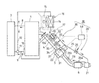
図1を参照して、排気熱回収装置の概略構成を説明する。図中、1は水冷式の内燃機関であり、この内燃機関1は、吸気系から供給される空気と燃料供給系から供給される燃料とを適宜の空燃比で混合してなる混合気を内燃機関1の燃焼室に供給して燃焼させた後、燃焼室内の排気ガスを排気系から大気放出させるようになっている。
A schematic configuration of the exhaust heat recovery apparatus will be described with reference to FIG. In the figure,
排気系は、内燃機関1に取り付けられるエキゾーストマニホールド2と、このエキゾーストマニホールド2に球面継手3を介して接続される排気管4とを少なくとも有する構成である。エキゾーストマニホールド2と排気管4とが、排気通路を構成している。
The exhaust system has at least an
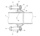
球面継手3は、図2に示すように、エキゾーストマニホールド2の下流側開口端に設けられた径方向外向きの平坦フランジ3aと、排気管4の上流側開口端に設けられた半球状フランジ3bと、平坦フランジ3aと半球状フランジ3bとの間に挟持されたガスケット3cと、平坦フランジ3aと半球状フランジ3bとを締結するためのボルト3dおよびナット3eと、ボルト3dと平坦フランジ3aとの間に圧縮状態で介装されたコイルスプリング3fとを含んだ構成になっている。
As shown in FIG. 2, the
ガスケット3cは、平坦フランジ3aに当たる側が平面に形成されており、半球状フランジ3bの内面に当たる側がそれに倣う半球面形状に形成されている。このガスケット3cは、コイルスプリング3fの弾性復元力により平坦フランジ3aとの当接面および半球状フランジ3bとの当接面をシールする。エキゾーストマニホールド2と排気管4とが揺動中心3gを中心に互いに揺動するような外力が作用したときには、ガスケット3cと半球状フランジ3bとの間で摺動することによって、前記揺動を無理なく許容するようになっている。つまり、この球面継手3は、内燃機関1の振動や動きを排気管4に伝達させないか、あるいは減衰して伝達するもので、請求項に記載の振動伝達減衰手段として機能する。
The
排気管4には、2つの触媒5,6が直列に設置されており、この2つの触媒5,6により排気ガスが浄化される。
Two
これらの触媒5,6のうち、排気管4において排気ガスの流れ方向の上流側に設置される触媒5は、いわゆるスタートキャタリスタ(S/C)と呼ばれるもので、上流側触媒と言うことにし、一方、排気管4において排気ガスの流れ方向の下流側に設置される触媒6は、いわゆるメインキャタリスト(M/C)またはアンダーフロアキャタリスタ(U/F)と呼ばれるもので、下流側触媒と言うことにする。
Among these
これらの触媒5,6は、共に、例えば三元触媒と呼ばれるものとすることができる。この三元触媒は、一酸化炭素(CO)、炭化水素(HC)、窒素酸化物(NOx)を一括して化学反応により無害な成分に変化させる、浄化作用を発揮するものである。
Both of these
内燃機関1には、その内部に封入されるロングライフクーラント(LLC)と呼ばれる冷媒(以下、単に冷却水と言う)が冷却水取り出し路8から一旦取り出されてラジエータ7に供給され、このラジエータ7から冷却水還流路9を経て内燃機関1に戻される。ラジエータ7は、ウォータポンプ10によって循環される冷却水を外気との熱交換により冷却するものである。
In the
そして、サーモスタット11によってラジエータ7を流通する冷却水量とバイパス流路12を流通する冷却水量とが調節されるようになっている。例えば暖機時においてはバイパス流路12側の冷却水量が増加されて暖機が促進され、ラジエータ7による冷却水の過冷却が防止される。
The amount of cooling water flowing through the
冷却水取り出し路8から分岐されて冷却水還流路9においてウォータポンプ10の上流側に接続されるヒータ流路13の途中には、ヒータコア14が設けられている。このヒータコア14は、前記の冷却水を利用して車室内の暖房を行うための熱源である。このヒータコア14によって暖められた空気は、ブロアファン15によって車室17内に導入されるようになっている。なお、前記のヒータコア14とブロアファン15とで温風ヒータ16が構成されている。ヒータ流路13においてヒータコア14より下流側領域を流れる冷却水の温度は、ヒータコア14からの放熱により低温になる。
A
このような構成の内燃機関1の排気系には、排気熱回収装置18が付設されている。
An exhaust
この排気熱回収装置18は、内燃機関1から排出される排気ガスの熱を取り込んで例えば上流側触媒5の昇温を促進させる処理や、上流側触媒5の熱を取り込んでヒータコア14から内燃機関1へ戻す冷却水の昇温を促進させる処理を行うことを可能としたもので、主として、2つのループ式ヒートパイプ20,30と、コントローラ40とを含んで構成されている。
The exhaust
第1ループ式ヒートパイプ20は、主として、第1受熱部21、第1放熱部22、第1移送路23、第1還流路24、第1弁装置25を含んで構成されている。第2ループ式ヒートパイプ30は、主として、第2受熱部31、第2放熱部32、第2移送路33、第2還流路34、第2弁装置35を含んで構成されている。
The first
これらのループ式ヒートパイプ20,30の内部全体には、真空状態とされた状態で作動流体が封入されている。この作動流体は、例えば純水等とされる。水の沸点は、1気圧で100℃であるが、ループ式ヒートパイプ20,30内を減圧(例えば0.01気圧)しているため、沸点は、例えば5〜10℃となる。なお、作動流体は、純水の他に、例えばアルコール、フロロカーボン、フロン等とすることが可能である。また、ループ式ヒートパイプ20,30の主要構成要素は、例えば高耐食性を備えるステンレス材で形成されている。
The inside of these
コントローラ40は、一般的に公知のECU(Electronic Control Unit)と同様、双方向性バスによって相互に接続した中央処理装置(CPU)、プログラムメモリ(ROM)、データメモリ(RAM)、バックアップメモリ(不揮発性RAM)等から構成されており、少なくとも排気熱回収装置18の動作を制御する。
The
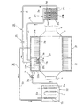
次に、第1ループ式ヒートパイプ20の構成要素について、図3を参照して詳細に説明する。
Next, components of the first
第1受熱部21は、排気管4において下流側触媒6より下流側に設置されており、内部に密封される液状の作動流体が排気熱を受けて蒸発することにより気化熱として熱を取り込むように構成されている。
The first
具体的に、受熱部21は、排気管4に対してその排気ガス通過方向と直交する方向に設置されるものであって、上部タンク21aと下部タンク21bとを複数本のチューブ21c・・・で連通させて、隣り合う各チューブ21cの対向隙間に、各チューブ21cの外壁面それぞれに接合されるフィン21d・・・を配置させたような構成になっている。
Specifically, the
前記隣り合う各チューブ21cの対向隙間が、排気管4内を流通する排気ガスの流通路になっている。この対向隙間に配置されるフィン21dは、前記対向隙間を通過する排気ガスとの熱交換面積を拡大するように、コルゲートタイプとされている。このコルゲートタイプのフィン21dとは、例えば薄肉の帯板材をローラ加工によって波形に成形したものである。要するに、排気ガスの熱をフィン21dが吸収してチューブ21c内を流通する作動流体を加熱、気化させるようになっている。したがって、チューブ21cとフィン21dとが、熱交換器となっている。
A facing gap between the
第1放熱部22は、上流側触媒5における上流領域に付設されており、第1受熱部21から移送される蒸気からなる作動流体でもって、上流側触媒5を加熱させることで作動流体を凝縮させるように構成されている。
The first
具体的に、第1放熱部22は、上流側触媒5における上流領域を包囲するような中空スリーブ22aと、この中空スリーブ22aの内周壁に接合される径方向外向きのフィン22b・・・とを含んだ構成とすることができる。
Specifically, the first
このフィン22bは、中空スリーブ22aの内部空間を通過する蒸気からなる作動流体との熱交換面積を拡大するように、コルゲートタイプとされている。このコルゲートタイプのフィン22bとは、例えば薄肉の帯板材をローラ加工によって円周方向に波形に成形したものである。 The fins 22b are of a corrugated type so as to expand the heat exchange area with the working fluid made of steam that passes through the internal space of the hollow sleeve 22a. The corrugated fins 22b are formed by, for example, forming a thin strip plate into a waveform in the circumferential direction by roller processing.
第1移送路23は、第1受熱部21で気化された作動流体を第1放熱部22へ移送するための配管である。この第1移送路23は、排気通路(排気管4、上流側触媒5ならびに下流側触媒6)の近傍に沿うように適宜のクリアランスを介して配置されている。
The
具体的に、第1移送路23と、排気通路(排気管4、上流側触媒5ならびに下流側触媒6)との離隔距離は、第1移送路23内を移送される蒸気からなる作動流体を凝縮させない温度を保つのに必要な寸法とされる。その寸法は、第1移送路23の全長寸法や、素材、肉厚、対向面積等に応じて、実験等によって把握し、経験的に設定することが好ましい。
Specifically, the separation distance between the
このような第1移送路23の配置を実現するために、第1移送路23の途中の複数箇所(この実施形態では2箇所)を、下流側触媒6の外壁と排気管4とに対し、ブラケット26a,26bを介して支持させている。このブラケット26a,26bは、熱伝導性の高い材料(例えばステンレス鋼等)とすることが好ましい。
In order to realize such an arrangement of the
第1還流路24は、第1放熱部22で凝縮された作動流体を第1受熱部21へ戻すための配管である。この第1還流路24は、前記した第1移送路23とは逆に、第1還流路24を流れる液状の作動流体が再び気化することがないように排気通路(排気管4、上流側触媒5ならびに下流側触媒6)や第1移送路23から可及的に遠くへ離れた位置に配置されている。しかも、この第1還流路24は、凝縮されて液状となった作動流体を受熱部21へ還流させやすくするために適宜の下り勾配がつけられている。
The
具体的に、第1還流路24と、排気通路(排気管4、上流側触媒5ならびに下流側触媒6)との離隔距離は、排気通路側からの輻射熱によって第1還流路24を流れる液状の作動流体が再蒸発しない状態を保つのに必要な寸法とされる。その寸法は、第1還流路23の全長寸法や、素材、肉厚、対向面積等に応じて、実験等によって把握し、経験的に設定することが好ましい。また、前記の下り勾配は、例えば6度程度とすることができるが、任意である。
Specifically, the separation distance between the
この第1還流路24の途中には、第1弁装置25が設けられている。この第1弁装置25は、第1放熱部22から第1受熱部21への作動流体の流通を、許容する開放状態と禁止する閉塞状態とに切り替えられるようなもので、例えば電磁弁とされている。
A
なお、コントローラ40により第1弁装置25の開度を無段階に制御することにより、第1放熱部22から第1受熱部21に作動流体を戻す量を調節するように設定することも可能である。
It is also possible to set the amount of return of the working fluid from the first
次に、第2ループ式ヒートパイプ30の構成要素について、図3を参照して詳細に説明する。
Next, components of the second
第2受熱部31は、上流側触媒5における下流領域に付設されており、内部に密封される液状の作動流体が上流側触媒5の熱を受けて蒸発することにより気化熱として熱を取り込むように構成されている。
The second
具体的に、第2受熱部31は、上流側触媒5における下流領域を包囲するような中空スリーブ31aと、この中空スリーブ31aの内周壁に接合される径方向外向きのフィン31b・・・とを含んだ構成とすることができる。このフィン31bは、中空スリーブ31aの内部空間を通過する蒸気からなる作動流体との熱交換面積を拡大するように、コルゲートタイプとされている。このコルゲートタイプのフィン31bとは、例えば薄肉の帯板材をローラ加工によって円周方向に波形に成形したものである。
Specifically, the second
第2放熱部32は、上流側触媒5と球面継手3との間で球面継手3寄りに付設されており、第2受熱部31から移送される蒸気からなる作動流体でもって、ヒータコア14から内燃機関1へ戻す冷却水を加熱させることにより作動流体を凝縮させるように構成されている。
The second
具体的に、第2放熱部32は、内部が密閉されたケース32aに第2移送路33の下流端および第2還流路34の上流端がそれぞれ接続された構成になっており、このケース32aの内部空間には、ヒータ流路13においてヒータコア14より下流側領域が挿入されている。このヒータ流路13においてケース32a内に挿入される領域は、その外周にフィン13aが設けられており、熱交換面積が拡大されている。動作としては、要するに、この第2放熱部32に、第2受熱部31で気化される作動流体が第2移送路33を経て移送されてくると、この作動流体の熱がフィン13aで吸収されて、この吸収された熱がヒータ流路13内を流通する冷却水を加熱するようになっている。
Specifically, the second
第2移送路33は、第2受熱部31で気化された作動流体を第2放熱部32へ移送するための配管である。第2還流路34は、第2放熱部32で凝縮された作動流体を第2受熱部31へ戻すための配管である。
The
この第2還流路34の途中には、第2弁装置35が設けられている。この第2弁装置35は、第2放熱部32から第2受熱部31への作動流体の流通を、許容する開放状態と禁止する閉塞状態とに切り替えられるようなもので、例えば電磁弁とされている。
A
なお、コントローラ40により第2弁装置35の開度を無段階に制御することにより、第2放熱部32から第2受熱部31に作動流体を戻す量を調節するように設定することも可能である。
It is also possible to set the amount of return of the working fluid from the second
この実施形態1では、図3に示すように、第1ループ式ヒートパイプ20の第1放熱部22と第2ループ式ヒートパイプ30の第2受熱部31とを、排気ガス通過方向に横並びに一体化した構造としている。
In the first embodiment, as shown in FIG. 3, the first
具体的に、第1放熱部22の中空スリーブ22aと第2受熱部31の中空スリーブ31aとが軸方向に隣り合わせに接合されている。この接合部には、連通路36が設けられており、この連通路36には、第3弁装置37が設けられている。
Specifically, the hollow sleeve 22a of the first
この第3弁装置37は、第1放熱部22から第2受熱部31への作動流体の流通を、許容する開放状態と禁止する閉塞状態とに切り替えられるようなもので、弁ケース37aと、弁体37bと、駆動源としてのアクチュエータ37cとを含んだ構成になっている。
The
なお、アクチュエータ37cの動作はコントローラ40により制御される。例えばコントローラ40は第3弁装置37の開度を無段階に制御することにより、第1放熱部22から第2受熱部31に作動流体を流通させる量を調節するようになっている。
The operation of the
次に、内燃機関1の動作に関連した排気熱回収装置18の動作について、まず簡単に説明する。
Next, the operation of the exhaust
要するに、内燃機関1を冷間始動する場合、上流側触媒5および下流側触媒6、内燃機関1の冷却水のすべてが低温になっているが、内燃機関1からエキゾーストマニホールド2を経て排気管4に例えば300〜400℃の排気ガスが排出されることになり、2つの触媒5,6が内部から排気ガスで昇温されることになる一方、冷却水がラジエータ7を通らずにバイパス流路12を経て内燃機関1へ戻されることによって暖機運転されることになる。
In short, when the
そこで、前記冷間始動時には、第2ループ式ヒートパイプ30を休止させることによりヒータコア14から内燃機関1へ戻す冷却水の加熱を休止しておいて、第1ループ式ヒートパイプ20の機能を有効にさせることにより、下流側触媒6を通過した排気熱でもって上流側触媒5を外側から加熱することを優先する。これにより、上流側触媒5が内側および外側の両方から加熱されるので、その昇温が促進されることになり、早期に活性化されることになる。なお、下流側触媒6は、上流側触媒5で浄化されることに伴い高温化する排気ガスによって昇温するようになる。
Therefore, at the time of cold start, the second
こうして、上流側触媒5が活性化温度にまで昇温すると、第1ループ式ヒートパイプ20を休止させることにより排気熱による上流側触媒5の加熱を休止しておいて、第2ループ式ヒートパイプ30の機能を有効にさせることにより、上流側触媒5の熱を回収してヒータコア14から内燃機関1へ戻す冷却水を加熱する。これにより、上流側触媒5を冷却しつつ、内燃機関1の暖機運転が促進されるようになる。
Thus, when the
この実施形態1では、排気熱回収装置18の第1ループ式ヒートパイプ20による熱循環の実行要否の制御を主としてコントローラ40と第1弁装置25とによって行うようにして、排気熱回収装置18の第2ループ式ヒートパイプ30による熱循環の実行要否の制御を主としてコントローラ40と第2弁装置35とによって行うようにしている。
In the first embodiment, the exhaust
次に、図4に示すフローチャートを参照して、排気熱回収装置18の動作について詳細に説明する。
Next, the operation of the exhaust
図4に示すフローチャートは、コントローラ40の動作を主体とするものであり、エントリーされると、まず、ステップS1において、上流側触媒5の温度Tscが第1閾値T1未満であるか否かを判定する。なお、上流側触媒5の温度Tscは、例えば上流側触媒5の触媒床温度を検出するセンサ(図示省略)からの検出出力に基づいて認識することができる。また、第1閾値T1は、例えば上流側触媒5が活性化する温度(例えば300〜400℃)に基づいて適宜に設定される。
The flowchart shown in FIG. 4 is mainly for the operation of the
要するに、前記のステップS1では、上流側触媒5が活性化しているか否か、つまり上流側触媒5の暖機が必要であるか否かを調べているのである。
In short, in step S1, whether or not the
ここで、前記ステップS1で肯定判定された場合、つまり上流側触媒5の温度Tscが上流側触媒5の活性化温度に到達していない場合には、上流側触媒5の暖機が必要であるとして、ステップS2に移行する。
Here, if an affirmative determination is made in step S1, that is, if the temperature Tsc of the
このステップS2では、第1弁装置25を開放することにより第1ループ式ヒートパイプ20の機能を有効、つまり熱循環を実行させて、第2弁装置35を閉塞することにより第2ループ式ヒートパイプ30の機能を休止、つまり熱循環を停止させる。そして、第3弁装置37を閉塞することにより第1放熱部22と第2受熱部31とを非連通にする。
In this step S2, the function of the first
まず、第1弁装置25を開放すると、第1受熱部21と第1放熱部22との間での作動流体の循環が許容されるので、第1ループ式ヒートパイプ20の機能が有効となるのである。これにより、内燃機関1から排気管4に排出された排気ガスが2つの触媒5,6を経て第1ループ式ヒートパイプ20の第1受熱部21に到達し、この第1受熱部21内の作動流体が前記排気ガスの熱により蒸発され、この蒸気からなる作動流体が第1移送路23を経て第1放熱部22へ移送される。このとき、第3弁装置37が閉塞されることによって第1放熱部22と第2受熱部31とが非連通となっているので、第1放熱部22内の蒸気からなる作動流体で上流側触媒5における上流領域が集中的に加熱されることになる。この加熱によって当該作動流体が凝縮されると、この凝縮された作動流体が第1還流路24を経て第1受熱部21に戻される。なお、上流側触媒5の昇温に伴い、その排気ガスの浄化作用によりその下流側の下流側触媒6も昇温されることになる。
First, when the
その一方で、第2弁装置35を閉塞すると、第2放熱部32で液化された作動流体を第2受熱部31へ戻せなくなるので、第2受熱部31で作動流体を蒸発させることができない状態となる。そのため、第2受熱部31から第2放熱部32へ蒸気からなる作動流体を移送できなくなるので、第2ループ式ヒートパイプ30の機能が休止状態になるのである。これにより、上流側触媒5の熱が回収されないので、上流側触媒5の昇温の妨げにならない。
On the other hand, when the
このような状態においては、第1受熱部21を通過する排気ガスの熱が回収されるので、この排気ガスのボリュームが減って、排気音が低減することになる。
In such a state, the heat of the exhaust gas passing through the first
ところで、前記ステップS1で否定判定された場合、つまり上流側触媒5の温度Tscが上流側触媒5の活性化温度以上になっている場合には、上流側触媒5の暖機が不要で、むしろ上流側触媒5の過剰昇温防止のための冷却が必要であるとして、ステップS3に移行する。
By the way, if a negative determination is made in step S1, that is, if the temperature Tsc of the
ステップS3では、内燃機関1から取り出される冷却水の温度Twが第2閾値T2未満であるか否かを判定する。なお、冷却水温度Twは、例えば内燃機関1から冷却水取り出し路8の上流側の温度を検出する水温センサ(図示省略)からの検出出力に基づいて認識することができる。また、第2閾値T2は、暖機運転が済んだ通常運転時の冷却水温度範囲(例えば60〜80℃)の下限温度よりも低い温度、つまり暖機運転が必要な温度として、例えば40℃に設定することができる。
In step S3, it is determined whether or not the temperature Tw of the cooling water taken out from the
要するに、前記のステップS3では、内燃機関1の暖機運転が必要であるか否かを調べているのである。
In short, in step S3, it is checked whether or not the warm-up operation of the
ここで、前記ステップS3で肯定判定された場合、つまり冷却水温度Twが通常運転時の温度よりも低い場合には、内燃機関1の暖機運転が必要であるとして、ステップS4に移行する。
Here, if an affirmative determination is made in step S3, that is, if the coolant temperature Tw is lower than the temperature during normal operation, it is determined that the warm-up operation of the
このステップS4では、第1弁装置25を閉塞することにより第1ループ式ヒートパイプ20の機能を休止、つまり熱循環を停止させて、第2弁装置35を開放することにより第2ループ式ヒートパイプ30の機能を有効、つまり熱循環を実行させる。そして、第3弁装置37を開放することにより第1放熱部22と第2受熱部31とを連通させる。
In this step S4, the function of the first
まず、第1弁装置25を閉塞すると、第1放熱部22で液化された作動流体を第1受熱部21へ戻せなくなるので、第1受熱部21で作動流体を蒸発させることができない状態となる。これにより、第1受熱部21から第1放熱部22へ蒸気からなる作動流体を移送できなくなるので、換言すれば熱の移送ができなくなるので、第1ループ式ヒートパイプ20の機能が休止状態になるのである。
First, when the
その一方で、第2弁装置35を開放すると、第2受熱部31と第2放熱部32との間での作動流体の循環が許容されるので、第2ループ式ヒートパイプ30の機能が有効となるのである。このとき、第3弁装置37を開放するので、第1放熱部22が第2受熱部31に連通した状態になり、そのために、第1放熱部22と第2受熱部31とが同体化して単一の受熱用熱交換部として機能するようになるので、第2受熱部31の受熱容量が大きくなったことになる。
On the other hand, when the
このような状態においては、上流側触媒5の熱を回収してヒータコア14から内燃機関1へ戻される冷却水を加熱するので、上流側触媒5が冷却されることになる。
In such a state, the heat of the
一方、前記ステップS3で否定判定された場合、つまり冷却水温度Twが通常運転時の温度範囲に収まっている場合には、ステップS5に移行する。 On the other hand, if a negative determination is made in step S3, that is, if the coolant temperature Tw is within the temperature range during normal operation, the process proceeds to step S5.
ステップS5では、上流側触媒5の温度Tscが第1閾値T1より大きい第3閾値T3以上であるか否かを判定する。なお、第3閾値T3は、例えば上流側触媒5の耐熱温度(例えば800〜900℃)に基づいて適宜に設定される。
In step S5, it is determined whether or not the temperature Tsc of the
要するに、前記のステップS5では、上流側触媒5が過剰に昇温しているか否かを調べているのである。
In short, in step S5, it is checked whether or not the
前記ステップS5で否定判定された場合、つまり上流側触媒5の温度Tscが過剰に昇温していない場合には、前記したステップS4に移行する。つまり、上流側触媒5が活性化温度に到達してから過剰に昇温するまでの間は、第2ループ式ヒートパイプ30のみの機能を有効として、上流側触媒5の熱を奪うようにしているのである。
If a negative determination is made in step S5, that is, if the temperature Tsc of the
ところで、前記ステップS5で肯定判定された場合、つまり上流側触媒5の温度Tscが過剰に昇温している場合には、ステップS6に移行して、さらに冷却水温度Twが第2閾値T2より大きい第4閾値T4以上であるか否かを判定する。
By the way, when an affirmative determination is made in step S5, that is, when the temperature Tsc of the
なお、第4閾値T4は、通常運転時の冷却水温度範囲(例えば60〜80℃)の上限温度より大きくかつオーバーヒート温度(例えば110℃)より小さい範囲で適宜に設定される。このように、第4閾値T4をオーバーヒート温度とせずに、それよりも小さい値に設定しているのは、オーバーヒートに至るまでの時間的な余裕を持たせるためである。 The fourth threshold T4 is appropriately set in a range that is higher than the upper limit temperature of the cooling water temperature range (eg, 60 to 80 ° C.) during normal operation and lower than the overheat temperature (eg, 110 ° C.). Thus, the reason why the fourth threshold value T4 is set to a value smaller than the overheat temperature is to allow time for the overheat.
要するに、前記のステップS6では、内燃機関1の冷却水がオーバーヒートしそうな傾向であるか否かを調べているのである。
In short, in step S6, it is checked whether or not the cooling water of the
前記ステップS6で肯定判定された場合、つまり上流側触媒5の温度Tscが過剰昇温していて、しかも冷却水温度Twが過剰昇温している状況であるので、上流側触媒5の暖機や冷却水の暖機を中止するために、ステップS7に移行する。
If an affirmative determination is made in step S6, that is, the temperature Tsc of the
このステップS7では、第1弁装置25を閉塞することにより第1ループ式ヒートパイプ20の機能を休止、つまり熱循環を停止させるとともに、第2弁装置35を閉塞することにより第2ループ式ヒートパイプ30の機能を休止、つまり熱循環を停止させたうえで、第3弁装置37を開放することにより第1放熱部22と第2受熱部31とを連通させる。
In step S7, the function of the first
まず、第1弁装置25を閉塞すると、第1放熱部22で液化された作動流体を第1受熱部21へ戻せなくなるので、第1受熱部21で作動流体を蒸発させることができない状態となる。これにより、第1受熱部21から第1放熱部22へ蒸気からなる作動流体を移送できなくなるので、第1ループ式ヒートパイプ20の機能が休止状態になるのである。
First, when the
また、第2弁装置35を閉塞すると、第2放熱部32で液化された作動流体を第2受熱部31へ戻せなくなるので、第2受熱部31で作動流体を蒸発させることができない状態となる。これにより、第2受熱部31から第2放熱部32へ蒸気からなる作動流体を移送できなくなるので、第2ループ式ヒートパイプ30の機能が休止状態になるのである。
Moreover, if the
それに加えて、第3弁装置37を開放しているので、第1放熱部22が第2受熱部31に連通した状態になり、その結果、第1放熱部22内の一部の作動流体が第2受熱部31へ流入し、第1放熱部22と第2受熱部31との両方で前記作動流体が蒸発されるようになって、第2放熱部32に移送されて貯留されることになる。そのためには、第2弁装置35を、第3弁装置37の開放後に閉塞するのが好ましい。
In addition, since the
このような状態が形成されると、上流側触媒5の加熱と、ヒータコア14から内燃機関1へ戻される冷却水の加熱とが中止されることになる。
When such a state is formed, the heating of the
一方、前記ステップS6で否定判定された場合、つまり上流側触媒5の温度Tscが過剰昇温しているが、冷却水温度Twが過剰昇温していない状況であるので、冷却水暖機が不要であるとして、ステップS8に移行する。
On the other hand, if a negative determination is made in step S6, that is, the temperature Tsc of the
ステップS8では、第1弁装置25を閉塞することにより第1ループ式ヒートパイプ20の機能を休止、つまり熱循環を停止させて、第2弁装置35を開放することにより第2ループ式ヒートパイプ30の機能を有効、つまり熱循環を実行させる。そして、第3弁装置37を開放することにより第1放熱部22と第2受熱部31とを連通させる。
In step S8, the function of the first
まず、第1弁装置25を閉塞すると、第1放熱部22で液化された作動流体を第1受熱部21へ戻せなくなるので、第1受熱部21で作動流体を蒸発させることができない状態となる。これにより、第1受熱部21から第1放熱部22へ蒸気からなる作動流体を移送できなくなるので、換言すれば熱の移送ができなくなるので、第1ループ式ヒートパイプ20による熱循環が停止されるのである。
First, when the
その一方で、第2弁装置35を開放すると、第2受熱部31と第2放熱部32との間での作動流体の循環が許容されるので、第2ループ式ヒートパイプ30の機能が有効となるのである。このとき、第3弁装置37を開放するので、第1放熱部22が第2受熱部31に連通した状態になり、そのために、第1放熱部22と第2受熱部31とが同体化して単一の受熱用熱交換部として機能するようになるので、第2受熱部31の受熱容量が大きくなったことになる。
On the other hand, when the
このような状態においては、下流側触媒6の下流の排気熱が上流側触媒5へ移送されなくなって、しかも、上流側触媒5の熱が第2放熱部32へ移送されることになるので、上流側触媒5が冷却されることになる。このとき、内燃機関1へ戻される冷却水の加熱は上流側触媒5の熱を利用して継続される。
In such a state, the exhaust heat downstream of the
なお、上述したステップS1〜S8の動作を制御するコントローラ40が、請求項5,6に記載の第1〜第4対処手段として機能する。ステップS1,S2が請求項5に記載の第1対処手段に相当し、ステップS1,S3,S4が請求項5に記載の第2対処手段に相当し、ステップS1,S3,S5,S6,S8が請求項6に記載の第3対処手段に相当し、ステップS5,S6,S7が請求項6に記載の第4対処手段に相当する。
In addition, the
以上説明したように、本発明を適用した実施形態1では、第1ループ式ヒートパイプ20を用いることにより内燃機関1から排出される排気ガスの熱を取り込んで上流側触媒5を外側から加熱してその昇温を促進することが可能になり、また、第2ループ式ヒートパイプ30を用いることにより上流側触媒5の熱を取り込んで当該上流側触媒5を冷却しつつ内燃機関1の冷却水の昇温を促進させることが可能になる。このように、内燃機関1に付設される触媒5,6の暖機や、内燃機関1の冷却水の暖機を効率よく行うことが可能になる。
As described above, in the first embodiment to which the present invention is applied, by using the first
しかも、上流側触媒5の温度や内燃機関1の水温が所定の上限値より上昇しようとするような状況においては、第1、第2ループ式ヒートパイプ20,30を共に休止させるようにし、それによって、上流側触媒5の過剰加熱による機能低下や、内燃機関1のオーバーヒートを未然に回避することが可能になる。
In addition, in a situation where the temperature of the
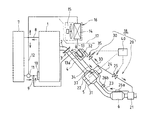
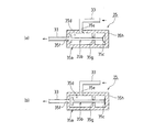
なお、この実施形態1に示した第2弁装置35は、例えば図5に示すように、第2移送路33に設置することも可能である。この場合の動作については、基本的に上記実施形態1と同じにできる。また、上記実施形態1に示した第1弁装置25についても、図示していないが、第1移送路23に設置することも可能である。この場合の動作については、基本的に上記実施形態1と同じにできる。
In addition, the
さらに、前記のように第2移送路33に設置する第2弁装置35は、予め設定される作動条件に従い自動的に開度を制御する自己作動タイプとすることができる。この自己作動タイプの第2弁装置35は、例えば図6に示すように、シリンダケース35aと、弁体35bと、ダイアフラムスプリング35cとを備えている。
Further, as described above, the
シリンダケース35aのシリンダ室35dの周壁には、作動流体の導入口35eが設けられており、シリンダ室35dの一端壁には、作動流体の排出口35fが設けられている。第2移送路33の途中を分断して、この分断された第2移送路33の第2受熱部31側の端部が導入口35eに連通連結されており、前記分断された第2移送路33の第2放熱部32側の端部が排出口35fに連通連結されている。
A working
シリンダ室35d内には、弁体35bが排出口35fを開放または閉塞するようにスライド可能に収納配置されている。シリンダ室35dの内周壁には、弁体35bのスライド動作をガイドするためのガイド壁35gが設けられている。
In the
弁体35bのバルブステムエンドは、ダイアフラムスプリング35cを介してシリンダ室35dの他端内壁面35hに取り付けられている。このダイアフラムスプリング35cは、上流側触媒5の温度Tscと相関関係を持つシリンダ室35dの内圧の変化によって弾性変形して伸びた形状になったり弾性復元して湾曲した形状になったりするものであり、この弾性変形や弾性復元に伴い弁体35bをスライドさせることで排出口35fを開閉させるようになっている。
The valve stem end of the
この自己作動タイプの第2弁装置35の動作を説明する。まず、上流側触媒5の活性化が必要であるという条件が成立した場合、つまりシリンダ室35dの内圧が規定値未満である場合には、図6(a)に示すように、ダイアフラムスプリング35cが湾曲した自然形状になって弁体35bが排出口35fを閉塞する。これにより、第2受熱部31内で蒸発された作動流体を第2放熱部32へ移送できなくなるので、第2ループ式ヒートパイプ30による熱循環が停止される。なお、前記規定値は、例えば上流側触媒5の活性化温度(第1閾値T1)と相関関係を持つ圧力値に設定される。
The operation of the self-actuating type
一方、上流側触媒5が活性化したという条件が成立した場合、つまりシリンダ室35dの内圧が前記規定値以上になった場合には、図6(b)に示すように、ダイアフラムスプリング35cが伸びる形状に弾性変形して弁体35bが排出口35fを開放する。これにより、第2受熱部31内で蒸発された作動流体を第2放熱部32へ移送できるようになるので、第2ループ式ヒートパイプ30による熱循環が実行される。
On the other hand, when the condition that the
(実施形態2)
図7から図9に本発明の実施形態2を示している。この実施形態2では、排気熱回収装置18の基本的な構成を上記実施形態1と同じにしているが、上記実施形態1で示したアクチュエータ駆動タイプの第2弁装置35を、自己作動タイプの第2弁装置50に変更したうえで、この第2弁装置50を第2移送路33に設置している。
(Embodiment 2)
7 to 9 show a second embodiment of the present invention. In the second embodiment, the basic configuration of the exhaust
この実施形態2では、排気熱回収装置18の第1ループ式ヒートパイプ20による熱循環の実行要否の制御を主としてコントローラ40と第1弁装置25とによって行うようにし、排気熱回収装置18の第2ループ式ヒートパイプ30による熱循環の実行要否の制御を主として自己作動タイプの第2弁装置50のみによって行うようにしている。
In the second embodiment, whether or not the heat circulation by the first
自己作動タイプの第2弁装置50は、図8(a)〜(c)に示すように、単一のシリンダケース51と、2つの弁体52,53と、ダイアフラムスプリング54,55とを備えている。シリンダケース51は、横長形状とされ、その内部には、3つのシリンダ室56,57,58が設けられている。
As shown in FIGS. 8A to 8C, the self-actuating type
第2移送路33の途中を分断して、この分断された第2移送路33の第2受熱部31側の端部が第1シリンダ室56に連通連結されており、前記分断された第2移送路33の第2放熱部32側の端部が第3シリンダ室58に連通連結されている。そして、第1シリンダ室56と第2シリンダ室57とを仕切る仕切り壁には、前記両シリンダ室56,57を連通するための第1連通路51aが設けられている。また、第2シリンダ室57と第3シリンダ室58とを仕切る仕切り壁には、前記両シリンダ室57,58を連通するための第2連通路51bが設けられている。
The middle of the
第1シリンダ室56には、第1弁体52が第1連通路51aを開放または閉塞するようにスライド可能に収納配置されている。この第1シリンダ室56内には、第1弁体52のスライド動作をガイドするためのガイド壁51cが設けられている。第1弁体52のバルブステムエンドは、第1ダイアフラムスプリング54を介して第1シリンダ室56の端壁面51dに取り付けられている。この第1ダイアフラムスプリング54は、上流側触媒5の温度Tscと相関関係を持つ第1シリンダ室56の内圧の変化によって弾性変形して伸びた形状になったり弾性復元して湾曲した形状になったりするものであり、この弾性変形や弾性復元に伴い第1弁体52をスライドさせることで第1連通路51aを開閉させるようになっている。
In the
第3シリンダ室58には、第2弁体53が第2連通路51bを開放または閉塞するようにスライド可能に収納配置されている。第2弁体53のバルブステムエンドは、第2ダイアフラムスプリング55を介して第3シリンダ室58の端壁面51eに取り付けられている。この第2ダイアフラムスプリング55は、内燃機関1から取り出される冷却水の温度と相関関係を持つ第2シリンダ室57の内圧の変化によって弾性復元して湾曲した形状になったり弾性変形して伸びた形状になったりするものであり、第2弁体53をスライドさせることで第2連通路51bを開閉させるようになっている。
In the
次に、自己作動タイプの第2弁装置50の動作を説明する。
Next, the operation of the self-actuating type
まず、上流側触媒5の活性化つまり暖機が必要であるという条件が成立した場合、つまり第1シリンダ室56の内圧が第1作動値未満である場合には、図8(a)に示すように、第1ダイアフラムスプリング54が弾性復元力で湾曲形状になって、第1弁体52が第1連通路51aを閉塞する位置にスライドされる。この状態では、第2移送路33と第1シリンダ室56とが非連通になるので、第2弁体53の開閉状態に関係なく、第2ループ式ヒートパイプ30による熱循環が停止される。なお、前記第1作動値は、例えば上流側触媒5の活性化温度(第1閾値T1)と相関関係を持つ圧力値に設定される。
First, when the condition that activation of the
しかし、上流側触媒5が活性化したという条件が成立した場合、つまり第1シリンダ室56の内圧が前記第1作動値以上になった場合には、図8(b)、(c)に示すように、第1ダイアフラムスプリング54が弾性復元力に抗して伸びた形状に弾性変形して、第1弁体52が第1連通路51aを開放する位置にスライドされる。この状態では、第2移送路33と第1シリンダ室56とが連通するので、第2弁体53が開放していれば第2ループ式ヒートパイプ30による熱循環が実行され、第2弁体53が閉塞していれば第2ループ式ヒートパイプ30による熱循環が停止される。
However, when the condition that the
また、内燃機関1から取り出される冷却水の加熱つまり暖機が必要でかつ昇温上限に到達していないという条件が成立した場合、つまり第2シリンダ室57の内圧が第2作動値以上で第3作動値未満であると、図8(a)、(b)に示すように、第2ダイアフラムスプリング55が弾性復元力で湾曲した形状になって、第2弁体53が第2連通路51bを開放する位置にスライドされる。この状態では、第2、第3シリンダ室57,58と第2放熱部32とが連通する。このときに、第1弁体52が開放していれば第2ループ式ヒートパイプ30による熱循環が実行されるが、第1弁体52が閉塞していれば第2ループ式ヒートパイプ30による熱循環が停止される。なお、前記第2作動値は、内燃機関1から取り出される冷却水の温度Twが昇温必要温度(第2閾値T2)と相関関係を持つ圧力値に設定される。前記第3作動値は、内燃機関1から取り出される冷却水の温度Twが昇温上限温度(第4閾値T4)と相関関係を持つ圧力値に設定される。
Further, when the condition that heating of the cooling water taken out from the
しかし、内燃機関1から取り出される冷却水が昇温上限に到達したという条件が成立した場合、つまり第2シリンダ室57の内圧が前記第3作動値以上になると、図8(c)に示すように、第2ダイアフラムスプリング55が弾性復元力に抗して伸びた形状に弾性変形して、第2弁体53が第2連通路51bを閉塞する位置にスライドされる。この状態では、第2、第3シリンダ室57,58と第2放熱部32とが非連通になるので、第1弁体52の開閉状態に関係なく、第2ループ式ヒートパイプ30による熱循環が停止される。
However, when the condition that the cooling water taken out from the
次に、図9を参照してコントローラ40の動作について詳細に説明する。図9に示すフローチャートは、コントローラ40による第1ループ式ヒートパイプ20の制御動作を主体とするものである。
Next, the operation of the
このフローチャートにエントリーされると、まず、ステップS11において、上流側触媒5の温度Tscが第1閾値T1未満であるか否かを判定する。なお、上流側触媒5の温度Tscは、例えば上流側触媒5の触媒床温度を検出するセンサ(図示省略)からの検出出力に基づいて認識することができる。また、第1閾値T1は、例えば上流側触媒5が活性化する温度(例えば300〜400℃)に基づいて適宜に設定される。
When entered in this flowchart, first, in step S11, it is determined whether or not the temperature Tsc of the
ここで、上流側触媒5の温度Tscが第1閾値T1未満である場合、前記ステップS11で肯定判定して、ステップS12に移行する。
Here, when the temperature Tsc of the
このステップS12では、第1弁装置25を開放することにより第1ループ式ヒートパイプ20による熱循環を実行させて、第3弁装置37を閉塞することにより第1放熱部22と第2受熱部31とを非連通にする。このとき、自己作動タイプの第2弁装置50については、図8(a)に示すように、第1ダイアフラムスプリング54が湾曲形状になって第1弁体52が第1連通路51aを閉塞するとともに、第2ダイアフラムスプリング55が湾曲状態になって第2弁体53が第2連通路51bを開放する状態になるので、第2ループ式ヒートパイプ30による熱循環が停止される。この結果、第2ループ式ヒートパイプ30で上流側触媒5の熱を回収せずに、第1ループ式ヒートパイプ20で下流側触媒6を通過した排気熱を回収して上流側触媒5を加熱させることができるので、上流側触媒5の昇温を促進することが可能になる。
In this step S12, the first
一方、上流側触媒5の温度Tscが第1閾値T1以上である場合、前記ステップS11で否定判定して、ステップS13において、内燃機関1の暖機運転が必要であるか否かを調べる。ここでは、内燃機関1から取り出される冷却水の温度Twが第2閾値T2未満であるか否かを判定する。
On the other hand, when the temperature Tsc of the
ここで、前記ステップS13で肯定判定された場合、つまり冷却水温度Twが通常運転時の温度よりも低い場合には、内燃機関1の暖機運転が必要であるとして、ステップS14に移行する。
Here, when an affirmative determination is made in step S13, that is, when the coolant temperature Tw is lower than the temperature during normal operation, it is determined that the warm-up operation of the
このステップS14では、第1弁装置25を閉塞することにより第1ループ式ヒートパイプ20による熱循環を停止させて、第3弁装置37を開放することにより第1放熱部22と第2受熱部31とを連通させる。このとき、自己作動タイプの第2弁装置50については、図8(b)に示すように、第2ダイアフラムスプリング55が湾曲形状になって第2弁体53が第2連通路51bを開放する状態になり、しかも、上流側触媒5の温度Tscが第1閾値T1以上になっていることに伴い、第1ダイアフラムスプリング54が伸びた形状になって第1弁体52が第1連通路51aを開放しているので、第2ループ式ヒートパイプ30による熱循環が行われるようになる。これらの結果、第1ループ式ヒートパイプ20による上流側触媒5の加熱が停止されたうえで、第2ループ式ヒートパイプ30で上流側触媒5の熱を回収してヒータ流路13内の冷却水を加熱するようになるので、この冷却水の昇温を促進しながら、上流側触媒5を冷却することが可能になる。
In step S14, the
その際、第3弁装置37を開放することにより第1放熱部22と第2受熱部31とを連通させて単一の大容量空間を作っているから、この大容量空間内に存在する作動流体によって上流側触媒5の熱を効率良く回収して第2放熱部32へ移送することが可能になる。
At that time, the
一方、前記ステップS13で否定判定された場合、つまり冷却水温度Twが通常運転時の温度範囲に収まっている場合には、ステップS15に移行する。 On the other hand, if a negative determination is made in step S13, that is, if the cooling water temperature Tw is within the temperature range during normal operation, the process proceeds to step S15.
このステップS15では、上流側触媒5の温度Tscが第1閾値T1より大きい第3閾値T3以上であるか否かを判定する。なお、第3閾値T3は、例えば上流側触媒5の耐熱温度(例えば800〜900℃)に基づいて適宜の昇温上限として設定される。このステップS15では、要するに、上流側触媒5が過剰に昇温しているか否かを調べているのである。
In step S15, it is determined whether or not the temperature Tsc of the
前記ステップS15で否定判定された場合、つまり上流側触媒5の温度Tscが過剰に昇温していない場合には、前記したステップS14に戻る。つまり、上流側触媒5が活性化温度に到達してから過剰に昇温するまでの間は、第1ループ式ヒートパイプ20による熱循環が停止されて第2ループ式ヒートパイプ30による熱循環が実行されるから、上流側触媒5を冷却することが可能になる。
If a negative determination is made in step S15, that is, if the temperature Tsc of the
ところで、前記ステップS15で肯定判定された場合、つまり上流側触媒5の温度Tscが過剰に昇温している場合には、ステップS16に移行して、さらに冷却水温度Twが第2閾値T2より大きい第4閾値T4以上であるか否かを判定する。
By the way, when an affirmative determination is made in step S15, that is, when the temperature Tsc of the
なお、第4閾値T4は、通常運転時の冷却水温度範囲(例えば60〜80℃)の上限温度より大きくかつオーバーヒート温度(例えば110℃)より小さい範囲で適宜に昇温上限として設定される。このように、第4閾値T4をオーバーヒート温度とせずに、それよりも小さい値に設定しているのは、オーバーヒートに至るまでの時間的な余裕を持たせるためである。 In addition, 4th threshold value T4 is suitably set as a temperature rising upper limit in the range larger than the upper limit temperature of the cooling water temperature range (for example, 60-80 degreeC) at the time of normal operation, and smaller than overheat temperature (for example, 110 degreeC). Thus, the reason why the fourth threshold value T4 is set to a value smaller than the overheat temperature is to allow time for the overheat.
要するに、前記のステップS16では、内燃機関1の冷却水がオーバーヒートしそうな傾向であるか否かを調べているのである。
In short, in step S16, it is checked whether or not the cooling water of the
前記ステップS16で肯定判定された場合、つまり上流側触媒5の温度Tscが過剰昇温していて、しかも冷却水温度Twが過剰昇温している状況であるので、上流側触媒5の暖機や冷却水の暖機を中止するために、ステップS17に移行する。
If an affirmative determination is made in step S16, that is, the temperature Tsc of the
このステップS17では、第1弁装置25を閉塞することにより第1ループ式ヒートパイプ20による熱循環を停止させて、第3弁装置37を開放することにより第1放熱部22と第2受熱部31とを連通させる。このとき、自己作動タイプの第2弁装置50については、図8(c)に示すように、第1ダイアフラムスプリング54が伸びた形状になって第1弁体52が第1連通路51aを開放する状態になるとともに、第2ダイアフラムスプリング55が伸びた形状になって第2弁体53が第2連通路51bを閉塞する状態になるので、第2ループ式ヒートパイプ30による熱循環が停止される。これらの結果、第1ループ式ヒートパイプ20による上流側触媒5の加熱が停止されるとともに、第2ループ式ヒートパイプ30による冷却水の加熱が停止されるので、上流側触媒5およびヒータ流路13内の冷却水が過剰に昇温することをそれぞれ防止することが可能になる。
In step S17, the
その際、第3弁装置37を開放することによって第1放熱部22と第2受熱部31とを連通させて単一の大容量空間を形成しているから、この大容量空間内に存在する作動流体によって上流側触媒5の熱を効率良く回収して大気に放熱することが可能になる。
At that time, by opening the
一方、前記ステップS16で否定判定された場合、つまり上流側触媒5の温度Tscが過剰昇温しているが、冷却水温度Twが過剰昇温していない状況であるので、冷却水暖機が不要であるとして、ステップS18に移行する。
On the other hand, if a negative determination is made in step S16, that is, the temperature Tsc of the
ステップS18では、第1弁装置25を閉塞することにより第1ループ式ヒートパイプ20による熱循環を停止させて、第3弁装置37を開放することにより第1放熱部22と第2受熱部31とを連通している。このとき、自己作動タイプの第2弁装置50については、図8(b)に示すように、上流側触媒5の温度Tscが第3閾値T3以上になっていることに伴い第1弁体52が第1連通路51aを開放しており、また、冷却水温度Twが第4閾値T4未満であることに伴い第2弁体53が第2連通路51bを開放しているので、第2ループ式ヒートパイプ30による熱循環が実行される。これらの結果、第1ループ式ヒートパイプ20による上流側触媒5の加熱が停止されたうえで、第2ループ式ヒートパイプ30により上流側触媒5の熱を回収してヒータ流路13内の冷却水を加熱するようになる。これにより、上流側触媒5が冷却される結果になる。
In step S <b> 18, the
その際、第3弁装置37を開放することによって第1放熱部22と第2受熱部31とを連通させて単一の大容量空間を作っているので、前記大容量空間内に存在する作動流体で上流側触媒5の熱を効率良く回収して大気に放熱できるようになって、上流側触媒5の冷却作用が高められる。
At this time, since the first
以上説明したように、この実施形態2では、上記実施形態1と同様の作用、効果が得られる他、自己作動タイプの第2弁装置50を用いることによって上記実施形態1に比べて構成簡素化、設備コストの低減を図ることが可能になる。
As described above, in the second embodiment, the same operation and effect as in the first embodiment can be obtained, and the configuration is simplified as compared with the first embodiment by using the
(実施形態3)
図10および図11に本発明の実施形態3を示している。この実施形態3では、排気熱回収装置18の基本的な構成を上記実施形態1と同じにしているが、上記実施形態1で示した第2弁装置35を無くし、その代わりに第2ループ式ヒートパイプ20にバイパス路61と切替弁62と大気放熱タンク63とを新たに設置している。
(Embodiment 3)
10 and 11 show a third embodiment of the present invention. In the third embodiment, the basic configuration of the exhaust
この実施形態3では、排気熱回収装置18の第1ループ式ヒートパイプ20による熱循環の実行要否の制御を主としてコントローラ40と第1弁装置25とによって行うようにして、排気熱回収装置18の第2ループ式ヒートパイプ30によるヒータ流路13内の冷却水への熱伝達の実行要否の制御を主としてコントローラ40と切替弁62とによって行うようにしている。
In the third embodiment, the exhaust
バイパス路61は、第2移送路33と第2還流路34とに第2放熱部32をバイパスするように接続されている。
The
切替弁62は、コントローラ40で切り替え制御されるアクチュエータ駆動タイプの三方弁とされており、バイパス路51において第2移送路33との接続部に設けられている。この切替弁62は、第2移送路33と第2放熱部32とを連通する熱交換経路X、あるいは第2移送路33とバイパス路51とを連通するバイパス経路Yを必要に応じて確保するように切り替えられる。
The switching
大気放熱タンク63は、バイパス路61の途中に設けられ、バイパス路51から導入される気相状の作動流体と大気とで熱交換させることにより凝縮させるものである。この大気放熱タンク63は、この実施形態3において、第2放熱部32と隣り合わせに設置されている。
The atmospheric
そして、切替弁62で熱交換経路Xを確保すると、第2ループ式ヒートパイプ30による冷却水への熱伝達が実行されるようになり、また、切替弁62でバイパス経路Yを確保すると、第2ループ式ヒートパイプ30によるヒータ流路13内の冷却水への熱伝達が停止されるようになる。
When the switching
次に、図11のフローチャートを参照して、この実施形態3による排気熱回収装置18の動作を説明する。図11に示すフローチャートは、コントローラ40の動作を主体とするものである。
Next, the operation of the exhaust
このフローチャートにエントリーされると、まず、ステップS21において、上流側触媒5の温度Tscが第1閾値T1未満であるか否かを判定する。なお、上流側触媒5の温度Tscは、例えば上流側触媒5の触媒床温度を検出するセンサ(図示省略)からの検出出力に基づいて認識することができる。また、第1閾値T1は、例えば上流側触媒5が活性化する温度(例えば300〜400℃)に基づいて適宜に設定される。
When entered in this flowchart, first, in step S21, it is determined whether or not the temperature Tsc of the
要するに、前記のステップS21では、上流側触媒5が活性化しているか否か、つまり上流側触媒5の活性化つまり暖機が必要であるか否かを調べているのである。
In short, in step S21, it is checked whether the
ここで、前記ステップS21で肯定判定された場合、つまり上流側触媒5の温度Tscが上流側触媒5の活性化温度に到達していない場合には、上流側触媒5の活性化つまり暖機が必要であるとして、ステップS22に移行する。
Here, when an affirmative determination is made in step S21, that is, when the temperature Tsc of the
このステップS22では、第1弁装置25を開放することにより第1ループ式ヒートパイプ20による熱循環を実行させて、切替弁60でバイパス経路Yを確保することにより第2ループ式ヒートパイプ30によるヒータ流路13内の冷却水への熱伝達を停止させる。そして、第3弁装置37を閉塞することにより第1放熱部22と第2受熱部31とを非連通にする。
In this step S22, the
まず、第1弁装置25を開放すると、第1受熱部21と第1放熱部22との間で作動流体が相転移しながら循環するようになるので、第1ループ式ヒートパイプ20の機能が有効となるのである。これにより、内燃機関1から排気管4に排出された排気ガスが2つの触媒5,6を経て第1ループ式ヒートパイプ20の第1受熱部21に到達し、この第1受熱部21内の作動流体が前記排気ガスの熱により蒸発され、この蒸気からなる作動流体が第1移送路23を経て第1放熱部22へ移送される。その際、第3弁装置37を閉塞することによって第1放熱部22と第2受熱部31とを非連通にしているので、第1放熱部22内の蒸気からなる作動流体で上流側触媒5における上流領域が集中的に加熱されることになる。この加熱によって当該作動流体が凝縮されると、この凝縮された作動流体が第1還流路24を経て第1受熱部21に戻される。なお、上流側触媒5の昇温に伴い、その排気ガスの浄化作用による反応熱で下流側触媒6も昇温されることになる。
First, when the
その一方で、切替弁62でバイパス経路Yを確保すると、第2受熱部31で蒸発された作動流体が第2放熱部32へ導入されずに大気放熱タンク63に導入されることになるので、第2放熱部32からヒータ流路13内の冷却水に熱を伝達できなくなる。このようにして第2ループ式ヒートパイプ30による冷却水への熱伝達が停止されるので、冷却水が加熱されなくなる。これにより、上流側触媒5が優先的に昇温される。
On the other hand, when the bypass path Y is secured by the switching
しかも、このような状態においては、第1受熱部21を通過する排気ガスの熱が回収されるので、この排気ガスのボリュームが減って、排気音が低減することになる。
Moreover, in such a state, the heat of the exhaust gas that passes through the first
ところで、前記ステップS21で否定判定された場合、つまり上流側触媒5の温度Tscが上流側触媒5の活性化温度以上になっている場合には、上流側触媒5の暖機が不要で、むしろ上流側触媒5の過剰昇温防止のための冷却が必要であるとして、ステップS23に移行する。
By the way, when a negative determination is made in step S21, that is, when the temperature Tsc of the
ステップS23では、内燃機関1から取り出される冷却水の温度Twが第2閾値T2未満であるか否かを判定する。なお、冷却水温度Twは、例えば内燃機関1から冷却水取り出し路8の上流側の温度を検出する水温センサ(図示省略)からの検出出力に基づいて認識することができる。また、第2閾値T2は、暖機運転が済んだ通常運転時の冷却水温度範囲(例えば60〜80℃)の下限温度よりも低い温度、つまり暖機運転が必要な温度として、例えば40℃に設定することができる。
In step S23, it is determined whether or not the temperature Tw of the cooling water taken out from the
要するに、前記のステップS23では、内燃機関1の冷却水の暖機つまり加熱が必要であるか否かを調べているのである。
In short, in step S23, it is checked whether or not the cooling water of the
ここで、前記ステップS23で肯定判定された場合、つまり冷却水温度Twが通常運転時の温度よりも低い場合には、内燃機関1の冷却水の暖機が必要であるとして、ステップS24に移行する。
If the determination in step S23 is affirmative, that is, if the cooling water temperature Tw is lower than the temperature during normal operation, it is determined that the cooling water of the
このステップS24では、第1弁装置25を閉塞することにより第1ループ式ヒートパイプ20による熱循環を停止させて、切替弁62で熱交換経路Xを確保することにより第2ループ式ヒートパイプ30によるヒータ流路13内の冷却水への熱伝達を実行させる。そして、第3弁装置37を開放することにより第1放熱部22と第2受熱部31とを連通させる。
In this step S24, the
まず、第1弁装置25を閉塞すると、第1放熱部22で液化された作動流体を第1受熱部21へ戻せなくなるので、第1受熱部21で作動流体を蒸発させることができない状態となる。これにより、第1受熱部21から第1放熱部22へ蒸気からなる作動流体を移送できなくなるので、換言すれば熱の移送ができなくなるので、第1ループ式ヒートパイプ20の機能が休止される。
First, when the
その一方で、切替弁62で熱交換経路Xを確保すると、第2受熱部31で蒸発された作動流体が第2放熱部32へ導入されることになるので、第2放熱部32内の気相状の作動流体とヒータ流路13内の冷却水との間で熱交換が行われるようになる。つまり、第2ループ式ヒートパイプ30によるヒータ流路13内の冷却水への熱伝達が実行される。その際、第3弁装置37を開放して第1放熱部22と第2受熱部31とを同体化させて単一の大容量空間を作っているので、この大容量空間内に存在する作動流体によって上流側触媒5の熱を効率良く回収して第2放熱部32へ移送することが可能になる。そのため、第2ループ式ヒートパイプ30によるヒータ流路13内の冷却水の加熱能力が高められることになるので、冷却水の昇温を促進するうえで有利となるとともに、上流側触媒5の過剰昇温を抑制するうえで有利となる。
On the other hand, if the heat exchange path X is secured by the switching
一方、前記ステップS23で否定判定された場合、つまり冷却水温度Twが通常運転時の温度範囲に収まっている場合には、ステップS25に移行する。 On the other hand, if a negative determination is made in step S23, that is, if the cooling water temperature Tw is within the temperature range during normal operation, the process proceeds to step S25.
ステップS25では、上流側触媒5の温度Tscが第1閾値T1より大きい第3閾値T3以上であるか否かを判定する。なお、第3閾値T3は、例えば上流側触媒5の耐熱温度(例えば800〜900℃)に基づいて適宜に設定される。
In step S25, it is determined whether or not the temperature Tsc of the
要するに、前記のステップS25では、上流側触媒5が過剰に昇温して昇温上限に到達しているか否かを調べているのである。
In short, in the above-described step S25, it is checked whether or not the
前記ステップS25で否定判定された場合、つまり上流側触媒5の温度Tscが昇温上限に到達していない場合には、前記したステップS24に戻る。つまり、上流側触媒5が活性化温度に到達してから昇温上限に到達するまでの間は、第2ループ式ヒートパイプ30により上流側触媒5の熱を回収して冷却水へ伝達させるようにする。
If a negative determination is made in step S25, that is, if the temperature Tsc of the
ところで、前記ステップS25で肯定判定された場合、つまり上流側触媒5の温度Tscが昇温上限に到達した場合には、ステップS26に移行して、さらに冷却水温度Twが第2閾値T2より大きい第4閾値T4以上であるか否かを判定する。
By the way, when an affirmative determination is made in step S25, that is, when the temperature Tsc of the
なお、第4閾値T4は、通常運転時の冷却水温度範囲(例えば60〜80℃)の上限温度より大きくかつオーバーヒート温度(例えば110℃)より小さい範囲で適宜に設定される。このように、第4閾値T4をオーバーヒート温度とせずに、それよりも小さい値に設定しているのは、オーバーヒートに至るまでの時間的な余裕を持たせるためである。 The fourth threshold T4 is appropriately set in a range that is higher than the upper limit temperature of the cooling water temperature range (eg, 60 to 80 ° C.) during normal operation and lower than the overheat temperature (eg, 110 ° C.). Thus, the reason why the fourth threshold value T4 is set to a value smaller than the overheat temperature is to allow time for the overheat.
要するに、前記のステップS26では、内燃機関1の冷却水がオーバーヒートしそうな傾向であるか否かを調べているのである。
In short, in step S26, it is checked whether or not the cooling water of the
前記ステップS26で肯定判定された場合、つまり上流側触媒5の温度Tscが昇温上限に到達していて、しかも冷却水の温度Twが昇温上限に到達している状況であるので、上流側触媒5の暖機や冷却水の暖機を中止するために、ステップS27に移行する。
If an affirmative determination is made in step S26, that is, the temperature Tsc of the
このステップS27では、第1弁装置25を閉塞することにより第1ループ式ヒートパイプ20による熱循環を停止させて、切替弁62でバイパス経路Yを確保することにより第2ループ式ヒートパイプ30によるヒータ流路13内の冷却水への熱伝達を停止させる。そして、第3弁装置37を開放することにより第1放熱部22と第2受熱部31とを連通させる。
In this step S27, the heat circulation by the first
まず、第1弁装置25を閉塞すると、第1放熱部22で液化された作動流体を第1受熱部21へ戻せなくなるので、第1受熱部21で作動流体を蒸発させることができない状態となる。これにより、第1受熱部21から第1放熱部22へ蒸気からなる作動流体を移送できなくなるので、第1ループ式ヒートパイプ20の機能が休止状態になって、上流側触媒5の加熱が中止されることになる。
First, when the
また、切替弁62でバイパス経路Yを確保すると、第2受熱部31で蒸発された作動流体が第2放熱部32へ導入されずに大気放熱用タンク63に導入されることになる。これにより、第2放熱部32からヒータ流路13内の冷却水に熱が伝達できなくなり、しかも、大気放熱用タンク63内に導入された気相状の作動流体の熱が大気に放熱されることになる。つまり、第2ループ式ヒートパイプ30により上流側触媒5の熱を回収するもののヒータ流路13内の冷却水への熱伝達が停止されることになるから、冷却水を加熱せずに上流側触媒5の温度を低下させることが可能になる。なお、大気放熱用タンク63内では、気相状の作動流体の熱が大気に放熱されることによって凝縮され、この凝縮された作動流体が第2還流路34を経て第2受熱部31に戻される。
Further, when the bypass path Y is secured by the switching
その際、第3弁装置37を開放して第1放熱部22と第2受熱部31とを連通させて単一の大容量空間を作っているから、この大容量空間内に存在する作動流体によって上流側触媒5の熱を効率良く回収することが可能になる等、上流側触媒5の冷却作用を高めるうえで有利になる。
At that time, since the
一方、前記ステップS26で否定判定された場合、つまり上流側触媒5の温度Tscが昇温上限に到達しているが、冷却水の温度Twが昇温上限に到達していない状況であるので、ステップS28に移行する。
On the other hand, if a negative determination is made in step S26, that is, the temperature Tsc of the
ステップS28では、第1弁装置25を閉塞することにより第1ループ式ヒートパイプ20による熱循環を停止させて、切替弁62で熱交換経路Xを確保することにより第2ループ式ヒートパイプ30によるヒータ流路13内の冷却水への熱伝達を実行させる。そして、第3弁装置37を開放することにより第1放熱部22と第2受熱部31とを連通させる。
In step S28, the
まず、第1弁装置25を閉塞すると、第1放熱部22で凝縮された作動流体を第1受熱部21へ戻せなくなるので、第1受熱部21で作動流体を蒸発させることができない状態となる。これにより、第1受熱部21から第1放熱部22へ蒸気からなる作動流体を移送できなくなるので、換言すれば熱の移送ができなくなるので、第1ループ式ヒートパイプ20の機能が休止状態になって、上流側触媒5の加熱が停止される。
First, when the
その一方で、切替弁62で熱交換経路Xを確保すると、第2受熱部31で蒸発された作動流体が第2放熱部32へ導入されることになるので、第2放熱部32内の気相状の作動流体とヒータ流路13内の冷却水との間で熱交換が行われるようになる。つまり、第2ループ式ヒートパイプ30による冷却水への熱伝達が実行される。その際、第3弁装置37を開放して第1放熱部22と第2受熱部31とを連通させて単一の大容量空間を作っているので、この大容量空間内に存在する作動流体によって上流側触媒5の熱を効率良く回収して第2放熱部32へ移送することが可能になる。そのため、上流側触媒5が冷却されることになる。
On the other hand, if the heat exchange path X is secured by the switching
以上説明したように、この実施形態3では、上記実施形態1と同様の作用、効果が得られる他、例えばバイパス経路Yを確保して第2ループ式ヒートパイプ30による熱循環を実行させたままヒータ流路13内の冷却水への熱伝達を停止させる状態とすれば、冷却水を加熱することなく上流側触媒5を冷却することが可能になる。
As described above, in the third embodiment, the same operation and effect as in the first embodiment can be obtained, and for example, the bypass path Y is secured and the heat circulation by the second
なお、本発明は、上記実施形態のみに限定されるものではなく、特許請求の範囲内および当該範囲と均等の範囲で包含されるすべての変形や応用が可能である。以下で例を挙げる。 In addition, this invention is not limited only to the said embodiment, All the deformation | transformation and application included in the range equivalent to the claim and the said range are possible. Examples are given below.
(1)上記各実施形態において、内燃機関1はガソリンエンジンやディーゼルエンジン、その他のエンジンに限定されるものではない。ディーゼルエンジンとする場合には、触媒5,6を例えばDPF(Diesel Particulate Filter)やDPNR(Diesel Particulate -NOx Reduction system)等とすることができる。
(1) In the above embodiments, the
なお、ディーゼルエンジンの場合において、上流側触媒5をNOx吸蔵還元触媒(NSR:NOx storage reduction)として、下流側触媒6をNOx選択還元触媒(SCR:Selective Catalytic Reduction)とすることも可能である。
In the case of a diesel engine, the
(2)上記各実施形態では、2つの触媒5,6を備える場合の例を挙げているが、触媒の数は限定されるものではなく、例えば1個、あるいは3個以上であってもよい。
(2) In each of the above embodiments, an example in which two
(3)上記各実施形態では、上流側触媒5に付設する第1放熱部22および第2受熱部31の外形について上流側触媒5を包囲するような環状とした例を挙げているが、第1放熱部22や第2受熱部31の外形形状は、特に限定されるものではない。第1放熱部22や第2受熱部31の外形形状は、例えば上流側触媒5の外壁面における一部領域に付設されるように湾曲した形状とすることも可能である。
(3) In each of the above embodiments, the outer shape of the first
(4)上記各実施形態では、第2ループ式ヒートパイプ30の第2放熱部32を球面継手3から上流側触媒5までの間に付設した例を挙げているが、第2放熱部32の設置場所は、特に限定されるものではない。例えば第2放熱部32は、排気通路(2,4)から離れた内燃機関1の冷却水取り出し路8寄りに設置することも可能である。
(4) In each said embodiment, although the example which attached the 2nd
(5)上記各実施形態では、第2ループ式ヒートパイプ30の第2放熱部32について温風ヒータ16のヒータコア14から内燃機関1へ戻す冷却水を加熱するのに用いるようにした例を挙げているが、本発明は、それに限定されるものではない。
(5) In each of the above embodiments, the second
例えば第2放熱部32により加熱する対象について、ヒータコア14へ導入する冷却水とすることも可能である。この場合、内燃機関1の暖機運転時に温風ヒータ16を作動させている状況において、ヒータコア14に導入する冷却水の昇温を促進させることが可能になるから、暖機運転での早期暖房が可能になる。
For example, the target to be heated by the second
また、第2放熱部32により加熱する対象について、バイパス流路12を流通する冷却水とすることも可能である。前記のバイパス流路12は、そもそも内燃機関1の暖機運転時等、冷却水を昇温させる必要がある場合に使用される流路である。したがって、バイパス流路12を流れる冷却水を第2放熱部32により昇温促進させることが可能になるから、内燃機関1の暖機運転を迅速に終了させることが可能になる。
Moreover, it is also possible to use the cooling water flowing through the
いずれの形態においても、加熱対象の昇温促進が不要な場合には、第2弁装置35を閉塞して、排気熱回収を休止状態にすればよい。
In any form, when it is not necessary to promote the temperature increase of the heating target, the
(6)上記各実施形態では、第3弁装置37について、アクチュエータ37cを駆動源とするタイプとしてコントローラ40で開度を制御するようにした例を挙げているが、この第3弁装置37は、詳細に図示していないが、ダイアフラムスプリングを駆動源として弁体を開閉させる自己作動タイプとすることも可能である。
(6) In each of the above embodiments, the
このダイアフラムスプリングを用いるタイプの弁装置は、例えば常温時に閉塞していて、第1放熱部22の内圧が所定の設定温度相当の圧力にまで高くなったときに、この圧力でダイアフラムスプリングを弾性変形させることによって弁体を変位させて開放させるような構成とすることができる。
This type of valve device using a diaphragm spring is closed at, for example, room temperature, and when the internal pressure of the first
(7)上記各実施形態では、第1放熱部22や第2受熱部31としてそれぞれ中空スリーブ22a,31aを用いる構成とした例を挙げているが、本発明はこれに限定されず、例えば図示していないが、中空スリーブ22a,31aを用いずに、当該中空スリーブ22a,31aの内周壁を無くしたようなケースを用いることが可能である。その場合、フィン22b,31bを上流側触媒5の外装ケースの外径側に設けるようにすればよい。
(7) In each of the above embodiments, an example is given in which the
(8)上記各実施形態において、図1には第1還流路24や第2還流路34を第1移送路23や第2移送路33より上側に配置したような例を挙げているが、本発明はこれに限定されず、例えば図示していないが、第1還流路24や第2還流路34を排気管4より下側に配置することも可能である。
(8) In each of the above embodiments, FIG. 1 shows an example in which the
1 内燃機関
2 エキゾーストマニホールド
3 球面継手
4 排気管
5 上流側触媒
6 下流側触媒
7 ラジエータ
8 冷却水取り出し路
9 冷却水還流路
10 ウォータポンプ
13 ヒータ流路
14 ヒータコア
16 温風ヒータ
18 排気熱回収装置
20 第1ループ式ヒートパイプ
21 第1受熱部
22 第1放熱部
23 第1移送路
24 第1還流路
25 第1弁装置
30 第2ループ式ヒートパイプ
31 第2受熱部
32 第2放熱部
33 第2移送路
34 第2還流路
35 第2弁装置
36 連通路
37 第3弁装置
DESCRIPTION OF
Claims (16)
前記第1ループ式ヒートパイプは、前記排気通路において触媒より下流側の排気熱により内部に密封される作動流体を気化させる第1受熱部と、前記触媒における上流領域に付設されかつ前記第1受熱部から移送される作動流体と触媒との間で熱交換させて前記作動流体を凝縮させる第1放熱部と、前記第1受熱部から前記第1放熱部へ作動流体を移送するための第1移送路と、前記第1放熱部から前記第1受熱部へ作動流体を戻すための第1還流路とを含み、
前記第2ループ式ヒートパイプは、前記触媒における下流領域に付設されかつ当該触媒の熱により内部に密封される作動流体を気化させる第2受熱部と、前記第2受熱部から移送される作動流体と前記内燃機関から一旦取り出される冷却水との間で熱交換させて前記作動流体を凝縮させる第2放熱部と、前記第2受熱部から前記第2放熱部へ作動流体を移送するための第2移送路と、前記第2放熱部から前記第2受熱部へ作動流体を戻すための第2還流路とを含む、ことを特徴とする排気熱回収装置。 The exhaust heat recovery apparatus according to claim 1,
The first loop type heat pipe is attached to an upstream region of the catalyst and has a first heat receiving portion for vaporizing a working fluid sealed inside by exhaust heat downstream of the catalyst in the exhaust passage, and the first heat receiving portion. A first heat radiating section for condensing the working fluid by exchanging heat between the working fluid transferred from the section and the catalyst, and a first for transferring the working fluid from the first heat receiving section to the first heat radiating section. A transfer path, and a first return path for returning the working fluid from the first heat radiation part to the first heat receiving part,
The second loop heat pipe includes a second heat receiving portion that is attached to a downstream region of the catalyst and that is sealed inside by heat of the catalyst, and a working fluid that is transferred from the second heat receiving portion. And a second heat radiating portion for condensing the working fluid by exchanging heat between the cooling water once taken out from the internal combustion engine and a second heat radiating portion for transferring the working fluid from the second heat receiving portion to the second heat radiating portion. An exhaust heat recovery apparatus comprising: a second transfer path; and a second reflux path for returning the working fluid from the second heat radiating unit to the second heat receiving unit.
前記第1還流路または第1移送路には第1弁装置が設けられ、前記第2還流路または第2移送路には第2弁装置が設けられる、ことを特徴とする排気熱回収装置。 The exhaust heat recovery apparatus according to claim 2,
An exhaust heat recovery apparatus, wherein a first valve device is provided in the first reflux path or the first transfer path, and a second valve device is provided in the second reflux path or the second transfer path.
前記第1放熱部と第2受熱部とには連通路が接続され、この連通路には第3弁装置が設けられる、ことを特徴とする排気熱回収装置。 The exhaust heat recovery apparatus according to claim 3,
An exhaust heat recovery apparatus, wherein a communication path is connected to the first heat radiating section and the second heat receiving section, and a third valve device is provided in the communication path.
前記第1、第2、第3弁装置は、それぞれコントローラで開度制御されるアクチュエータ駆動タイプとされ、
前記コントローラは、前記触媒の活性化が必要であると判定した場合に、前記第1弁装置を開放して前記第2、第3弁装置を共に閉塞する第1対処手段と、
前記触媒が活性化している状態において前記冷却水の加熱が必要であると判定した場合に、前記第1弁装置を閉塞して前記第2、第3弁装置を共に開放する第2対処手段とを含む、ことを特徴とする排気熱回収装置。 The exhaust heat recovery apparatus according to claim 4,
Each of the first, second and third valve devices is an actuator drive type whose opening degree is controlled by a controller.
The controller, when it is determined that the activation of the catalyst is necessary, a first coping means for opening the first valve device and closing both the second and third valve devices;
Second coping means for closing the first valve device and opening the second and third valve devices when it is determined that heating of the cooling water is necessary in a state where the catalyst is activated; An exhaust heat recovery device comprising:
前記コントローラは、前記触媒が活性化している状態において昇温上限に到達していないと判定し、かつ、前記冷却水の暖機が済んでいる状態において昇温上限に到達していないと判定した場合に、前記第1弁装置を閉塞して前記第2、第3弁装置を共に開放する第3対処手段と、
前記触媒が昇温上限に到達したと判定しかつ前記冷却水が昇温上限に到達したと判定した場合に、前記第1、第2弁装置を共に閉塞して前記第3弁装置を開放する第4対処手段とをさらに含む、ことを特徴とする排気熱回収装置。 The exhaust heat recovery apparatus according to claim 5,
The controller determines that the temperature increase upper limit has not been reached in a state where the catalyst is activated, and has determined that the temperature increase upper limit has not been reached in a state where the cooling water has been warmed up. A third coping means for closing the first valve device and opening the second and third valve devices together,
When it is determined that the catalyst has reached the upper limit of temperature rise and it is determined that the cooling water has reached the upper limit of temperature rise, both the first and second valve devices are closed and the third valve device is opened. The exhaust heat recovery apparatus further comprising a fourth coping means.
前記第1還流路または第1移送路には第1弁装置が設けられ、
前記第2移送路と第2還流路とには前記第2放熱部をバイパスするバイパス路が接続され、このバイパス路において前記第2移送路との接続部には第2移送路から第2放熱部へ向かう熱交換経路あるいは第2移送路からバイパス路へ向かうバイパス経路を必要に応じて確保するための切替弁が設けられる、ことを特徴とする排気熱回収装置。 The exhaust heat recovery apparatus according to claim 2,
A first valve device is provided in the first reflux path or the first transfer path,
A bypass path that bypasses the second heat radiating portion is connected to the second transfer path and the second reflux path, and a second heat radiating from the second transfer path to the connection portion with the second transfer path in the bypass path. An exhaust heat recovery apparatus, characterized in that a switching valve is provided for securing a heat exchange path toward the section or a bypass path from the second transfer path to the bypass path as necessary.
前記第1弁装置は、コントローラで開度制御されるアクチュエータ駆動タイプとされ、前記切替弁は、前記コントローラで切り替え制御されるアクチュエータ駆動タイプの三方弁とされ、
前記コントローラは、前記触媒の活性化が必要であると判定した場合に前記第1弁装置を開放して前記切替弁でバイパス経路を確保する第1対処手段と、
前記触媒が活性化している状態において前記冷却水の加熱が必要であると判定した場合に前記第1弁装置を閉塞して前記切替弁で熱交換経路を確保する第2対処手段と、
前記冷却水が昇温上限に到達したと判定した場合に、前記第1弁装置を閉塞して前記切替弁でバイパス経路を確保する第3対処手段とを含む、ことを特徴とする排気熱回収装置。 The exhaust heat recovery apparatus according to claim 7,
The first valve device is an actuator drive type whose opening degree is controlled by a controller, and the switching valve is an actuator drive type three-way valve which is switch-controlled by the controller,
The controller, when it is determined that the catalyst needs to be activated, opens the first valve device and secures a bypass path with the switching valve;
Second coping means for closing the first valve device and securing a heat exchange path with the switching valve when it is determined that heating of the cooling water is necessary in a state where the catalyst is activated;
Exhaust heat recovery comprising: a third coping means for closing the first valve device and securing a bypass path with the switching valve when it is determined that the cooling water has reached the upper limit of temperature rise apparatus.
前記第1放熱部と第2受熱部とには連通路が接続され、この連通路には第3弁装置が設けられる、ことを特徴とする排気熱回収装置。 The exhaust heat recovery apparatus according to claim 7,
An exhaust heat recovery apparatus, wherein a communication path is connected to the first heat radiating section and the second heat receiving section, and a third valve device is provided in the communication path.
前記第1弁装置は、コントローラで開度制御されるアクチュエータ駆動タイプとされ、前記切替弁は、前記コントローラで切り替え制御されるアクチュエータ駆動タイプの三方弁とされ、前記第3弁装置は、前記コントローラで開度制御されるアクチュエータ駆動タイプとされ、
前記コントローラは、前記触媒の活性化が必要であると判定した場合に前記第1弁装置を開放、前記第3弁装置を閉塞、さらに前記切替弁でバイパス経路を確保する第1対処手段と、
前記触媒が活性化している状態において前記冷却水の加熱が必要であると判定した場合に前記第1弁装置を閉塞、前記第3弁装置を開放、さらに前記切替弁で熱交換経路を確保する第2対処手段と、
前記冷却水が昇温上限に到達したと判定した場合に、前記第1弁装置を閉塞、前記第3弁装置を開放、さらに前記切替弁でバイパス経路を確保する第3対処手段とを含む、ことを特徴とする排気熱回収装置。 The exhaust heat recovery apparatus according to claim 9,
The first valve device is an actuator driving type whose opening degree is controlled by a controller, the switching valve is an actuator driving type three-way valve controlled by the controller, and the third valve device is the controller It is an actuator drive type whose opening is controlled by
The controller opens the first valve device, closes the third valve device, and further secures a bypass path with the switching valve when it is determined that the activation of the catalyst is necessary;
When it is determined that heating of the cooling water is necessary in a state where the catalyst is activated, the first valve device is closed, the third valve device is opened, and a heat exchange path is secured by the switching valve. Second coping means;
A third coping means for closing the first valve device, opening the third valve device, and securing a bypass path with the switching valve when it is determined that the cooling water has reached the upper limit of temperature increase; An exhaust heat recovery device.
前記第1弁装置は、予め設定される作動条件に従い自動的に開度を制御する自己作動タイプとされ、かつ、前記触媒の活性化が必要であるという条件が成立した場合に開放し、前記触媒が活性化している状態において前記冷却水の加熱が必要であるという条件が成立した場合に閉塞する、ことを特徴とする排気熱回収装置。 The exhaust heat recovery apparatus according to claim 3 or 7,
The first valve device is a self-actuating type that automatically controls the opening according to a preset operating condition, and is opened when a condition that activation of the catalyst is necessary is established, An exhaust heat recovery apparatus, which is closed when a condition that heating of the cooling water is necessary in a state where the catalyst is activated is established.
前記第2弁装置は、予め設定される作動条件に従い自動的に開度を制御する自己作動タイプとされ、かつ、前記触媒の活性化が必要であるという条件が成立した場合に閉塞し、前記触媒が活性化したという条件が成立した場合に開放する、ことを特徴とする排気熱回収装置。 The exhaust heat recovery apparatus according to claim 3,
The second valve device is a self-actuating type that automatically controls the opening according to a preset operating condition, and closes when a condition that activation of the catalyst is necessary is satisfied, An exhaust heat recovery apparatus, which is opened when a condition that the catalyst is activated is satisfied.
前記第2弁装置は、予め設定される作動条件に従い自動的に開度を制御する自己作動タイプとされ、かつ、前記触媒の活性化が必要であるという条件が成立した場合あるいは前記冷却水が昇温上限に到達したと判定した場合に閉塞し、前記触媒が活性化している状態において前記冷却水の加熱が必要であるという条件が成立した場合に開放する、ことを特徴とする排気熱回収装置。 The exhaust heat recovery apparatus according to claim 3,
The second valve device is of a self-actuating type that automatically controls the opening according to preset operating conditions, and when the condition that the catalyst needs to be activated is satisfied or the cooling water is Exhaust heat recovery, which is closed when it is determined that the temperature rise upper limit has been reached, and is opened when the condition that heating of the cooling water is necessary in a state where the catalyst is activated is established. apparatus.
前記第3弁装置は、予め設定される作動条件に従い自動的に開度を制御する自己作動タイプとされ、かつ、前記触媒の活性化が必要であるという条件が成立した場合に閉塞し、前記触媒が活性化している状態において前記冷却水の加熱が必要であるという条件が成立した場合あるいは前記冷却水が昇温上限に到達したという条件が成立した場合に開放する、ことを特徴とする排気熱回収装置。 The exhaust heat recovery apparatus according to claim 4 or 9,
The third valve device is a self-actuating type that automatically controls the opening according to a preset operating condition, and closes when a condition that activation of the catalyst is necessary is satisfied, Exhaust gas that opens when a condition that heating of the cooling water is necessary in a state where the catalyst is activated or when a condition that the cooling water reaches the upper limit of temperature rise is satisfied Heat recovery device.
前記第1放熱部は、前記触媒における上流領域を包囲するように設けられかつ内部環状空間に前記第1移送路および第1還流路が連通連結される第1中空スリーブと、この第1中空スリーブの内周壁に設けられる径方向外向きのフィンとを含み、
前記第2受熱部は、前記触媒における下流領域を包囲するように設けられかつ内部環状空間に前記第2移送路および第2還流路が連通連結される第2中空スリーブと、この第2中空スリーブの内周壁に設けられる径方向外向きのフィンとを含み、
前記両中空スリーブは、軸方向隣り合わせに接合され、この接合部に前記連通路が設けられる、ことを特徴とする排気熱回収装置。 In the exhaust heat recovery device according to any one of claims 4, 5, 6, 9, and 10,
The first heat dissipating part is provided so as to surround an upstream region of the catalyst, and the first transfer sleeve and the first return path are connected to the internal annular space, and the first hollow sleeve. Including radially outward fins provided on the inner peripheral wall of the
The second heat receiving portion is provided so as to surround the downstream region of the catalyst, and the second transfer sleeve and the second reflux passage are connected to the internal annular space, and the second hollow sleeve. Including radially outward fins provided on the inner peripheral wall of the
The two hollow sleeves are joined side by side in the axial direction, and the communication path is provided at the joined portion.
前記排気通路における内燃機関寄りの位置には、振動伝達減衰手段が設けられ、前記第2放熱部は、前記振動伝達減衰手段から前記触媒までの間の領域に付設される、ことを特徴とする排気熱回収装置。 In the exhaust heat recovery device according to any one of claims 2 to 15,
Vibration transmission attenuation means is provided at a position near the internal combustion engine in the exhaust passage, and the second heat radiating portion is provided in a region between the vibration transmission attenuation means and the catalyst. Exhaust heat recovery device.
Priority Applications (7)
| Application Number | Priority Date | Filing Date | Title |
|---|---|---|---|
| JP2009148818A JP2010059960A (en) | 2008-08-08 | 2009-06-23 | Exhaust heat recovery device |
| PCT/IB2009/006842 WO2010015940A2 (en) | 2008-08-08 | 2009-08-07 | Exhaust heat recovery system |
| AT09786252T ATE535688T1 (en) | 2008-08-08 | 2009-08-07 | EXHAUST GAS HEAT RECOVERY SYSTEM |
| CN200980129432XA CN102105661B (en) | 2008-08-08 | 2009-08-07 | Exhaust heat recovery system |
| US13/057,894 US20110131962A1 (en) | 2008-08-08 | 2009-08-07 | Exhaust heat recovery system |
| RU2011104200/06A RU2459092C1 (en) | 2008-08-08 | 2009-08-07 | Off gas heat recovery system |
| EP09786252A EP2318676B1 (en) | 2008-08-08 | 2009-08-07 | Exhaust heat recovery system |
Applications Claiming Priority (2)
| Application Number | Priority Date | Filing Date | Title |
|---|---|---|---|
| JP2008205285 | 2008-08-08 | ||
| JP2009148818A JP2010059960A (en) | 2008-08-08 | 2009-06-23 | Exhaust heat recovery device |
Publications (1)
| Publication Number | Publication Date |
|---|---|
| JP2010059960A true JP2010059960A (en) | 2010-03-18 |
Family
ID=41510864
Family Applications (1)
| Application Number | Title | Priority Date | Filing Date |
|---|---|---|---|
| JP2009148818A Pending JP2010059960A (en) | 2008-08-08 | 2009-06-23 | Exhaust heat recovery device |
Country Status (7)
| Country | Link |
|---|---|
| US (1) | US20110131962A1 (en) |
| EP (1) | EP2318676B1 (en) |
| JP (1) | JP2010059960A (en) |
| CN (1) | CN102105661B (en) |
| AT (1) | ATE535688T1 (en) |
| RU (1) | RU2459092C1 (en) |
| WO (1) | WO2010015940A2 (en) |
Cited By (7)
| Publication number | Priority date | Publication date | Assignee | Title |
|---|---|---|---|---|
| JP2010084546A (en) * | 2008-09-30 | 2010-04-15 | Isuzu Motors Ltd | Exhaust emission control system and exhaust emission control method |
| WO2012032652A1 (en) | 2010-09-10 | 2012-03-15 | トヨタ自動車株式会社 | Electrically heated catalyst |
| JP2015148355A (en) * | 2014-02-05 | 2015-08-20 | 古河電気工業株式会社 | Waste-heat recovery unit and waste-heat utilization system |
| US9121322B2 (en) | 2010-08-31 | 2015-09-01 | Toyota Jidosha Kabushiki Kaisha | Electrically heated catalyst |
| WO2016129044A1 (en) * | 2015-02-09 | 2016-08-18 | 富士通株式会社 | Cooling device and electronic apparatus |
| JP2017190773A (en) * | 2016-03-31 | 2017-10-19 | マン・ディーゼル・アンド・ターボ・エスイー | Exhaust gas aftertreatment system, internal combustion engine and operating method for the same |
| US11208938B2 (en) | 2018-10-22 | 2021-12-28 | Hyundai Motor Company | Exhaust tail trim for vehicle |
Families Citing this family (28)
| Publication number | Priority date | Publication date | Assignee | Title |
|---|---|---|---|---|
| DE102008041874A1 (en) * | 2008-09-08 | 2010-03-11 | Robert Bosch Gmbh | Apparatus and method for operating an internal combustion engine, computer program, computer program product |
| JP5331026B2 (en) * | 2010-02-18 | 2013-10-30 | トヨタ自動車株式会社 | Waste heat recovery device |
| DE102011002629B4 (en) * | 2011-01-13 | 2014-02-13 | Eberspächer Exhaust Technology GmbH & Co. KG | Component of an exhaust system with at least one heat exchanger |
| WO2012109126A1 (en) | 2011-02-08 | 2012-08-16 | Dow Global Technologies Llc | System and method for reducing emissions from a combustion process |
| US8806858B2 (en) * | 2012-01-19 | 2014-08-19 | Ford Global Technologies, Llc | Method to protect the exhaust manifold from overheating using heat pipe |
| US8839613B2 (en) * | 2012-02-06 | 2014-09-23 | Ford Global Technologies, Llc | Heat system for an engine |
| US8661800B2 (en) | 2012-04-09 | 2014-03-04 | Ford Global Technologies, Llc | Method of collection and reuse of exhaust heat in a diesel-powered vehicle |
| FR2993046B1 (en) * | 2012-07-05 | 2018-07-20 | Psa Automobiles Sa. | BATTERY COMPARTMENT COMPRISING A HEATER PROVIDED NEAR AN EXHAUST LINE |
| US20140042234A1 (en) * | 2012-08-09 | 2014-02-13 | Cooper-Standard Automotive, Inc. | System, apparatus and method for quick warm-up of a motor vehicle |
| CN103670624B (en) * | 2012-09-21 | 2016-02-17 | 上海汽车集团股份有限公司 | Tail gas heat quantity is utilized to carry out the system of energy regenerating and be configured with the automobile of this system |
| FR3000133B1 (en) * | 2012-12-26 | 2015-01-16 | Renault Sa | EXHAUST LINE OF A MOTOR VEHICLE HAVING AN IMPROVED BALL |
| US20150107242A1 (en) * | 2013-10-18 | 2015-04-23 | GM Global Technology Operations LLC | Exhaust system with post-operation cooling for a vehicle, and a method thereof |
| JP5563176B1 (en) * | 2013-10-31 | 2014-07-30 | 中国電力株式会社 | Engine exhaust heat recovery device |
| JP6079582B2 (en) * | 2013-11-22 | 2017-02-15 | トヨタ自動車株式会社 | Exhaust treatment device |
| GB2545204A (en) * | 2015-12-08 | 2017-06-14 | Gm Global Tech Operations Llc | A heat management system for an automotive system |
| FR3057021A1 (en) * | 2016-10-04 | 2018-04-06 | Peugeot Citroen Automobiles Sa | DEVICE FOR TREATING EXHAUST GASES |
| CN106677870A (en) * | 2016-12-26 | 2017-05-17 | 天津大学 | Running device and control method for improving emission of cold starting of automobile through exhaust air energy recovering |
| NO20170547A1 (en) | 2017-04-03 | 2018-05-22 | Tegma As | A device for generating electric power for installation to an exhaust conduit |
| WO2018219476A1 (en) * | 2017-06-02 | 2018-12-06 | Volvo Truck Corporation | A method for controlling the temperature of a nox controlling component and an exhaust after treatment system |
| GB2564431B (en) * | 2017-07-10 | 2019-07-17 | Ford Global Tech Llc | A system and method for heating a vehicle catalytic converter |
| JP6805987B2 (en) * | 2017-07-10 | 2020-12-23 | トヨタ自動車株式会社 | Exhaust heat recovery structure |
| GB2564520B (en) * | 2017-07-10 | 2019-07-17 | Ford Global Tech Llc | A system and method for heating a vehicle catalytic converter |
| JP6815947B2 (en) * | 2017-07-25 | 2021-01-20 | トヨタ自動車株式会社 | Exhaust heat recovery structure |
| US10428713B2 (en) | 2017-09-07 | 2019-10-01 | Denso International America, Inc. | Systems and methods for exhaust heat recovery and heat storage |
| WO2020118095A1 (en) | 2018-12-06 | 2020-06-11 | OctoTech, Inc. | Rf receiver architectures with parametric circuits |
| DE102019120283B4 (en) * | 2019-07-26 | 2024-05-02 | Deutsches Zentrum für Luft- und Raumfahrt e.V. | Engine system and method for operating an engine system |
| US11668219B2 (en) * | 2020-09-28 | 2023-06-06 | Nooter/Eriksen, Inc. | System and method for treating process exhaust gas |
| GB2608401A (en) * | 2021-06-30 | 2023-01-04 | Daimler Ag | Exhaust heat recovery system for a conventional vehicle as well as hybrid vehicle |
Family Cites Families (9)
| Publication number | Priority date | Publication date | Assignee | Title |
|---|---|---|---|---|
| US4391235A (en) * | 1981-05-28 | 1983-07-05 | Majkrzak David S | Vehicle exhaust gas warm-up heater system |
| SU1321879A1 (en) * | 1985-04-17 | 1987-07-07 | Донецкий политехнический институт | Device for recovering waste heat of internal combustion engine exhaust gases |
| JPS6322321U (en) * | 1986-07-30 | 1988-02-15 | ||
| DE4340463C2 (en) * | 1993-11-27 | 1995-11-09 | Webasto Thermosysteme Gmbh | Exhaust system |
| JP4085998B2 (en) * | 2004-03-22 | 2008-05-14 | トヨタ自動車株式会社 | Waste heat recovery device |
| DE102004061809A1 (en) * | 2004-12-22 | 2006-07-06 | Robert Bosch Gmbh | Heating and / or cooling system for a motor vehicle |
| JP2007278623A (en) * | 2006-04-07 | 2007-10-25 | Denso Corp | Exhaust heat recovery system |
| JP2008014304A (en) * | 2006-06-08 | 2008-01-24 | Denso Corp | Exhaust heat recovery equipment |
| WO2007142292A1 (en) * | 2006-06-08 | 2007-12-13 | Denso Corporation | Exhaust heat recovery equipment |
-
2009
- 2009-06-23 JP JP2009148818A patent/JP2010059960A/en active Pending
- 2009-08-07 AT AT09786252T patent/ATE535688T1/en active
- 2009-08-07 CN CN200980129432XA patent/CN102105661B/en not_active Expired - Fee Related
- 2009-08-07 WO PCT/IB2009/006842 patent/WO2010015940A2/en active Application Filing
- 2009-08-07 RU RU2011104200/06A patent/RU2459092C1/en not_active IP Right Cessation
- 2009-08-07 US US13/057,894 patent/US20110131962A1/en not_active Abandoned
- 2009-08-07 EP EP09786252A patent/EP2318676B1/en not_active Not-in-force
Cited By (10)
| Publication number | Priority date | Publication date | Assignee | Title |
|---|---|---|---|---|
| JP2010084546A (en) * | 2008-09-30 | 2010-04-15 | Isuzu Motors Ltd | Exhaust emission control system and exhaust emission control method |
| US9121322B2 (en) | 2010-08-31 | 2015-09-01 | Toyota Jidosha Kabushiki Kaisha | Electrically heated catalyst |
| WO2012032652A1 (en) | 2010-09-10 | 2012-03-15 | トヨタ自動車株式会社 | Electrically heated catalyst |
| US9017615B2 (en) | 2010-09-10 | 2015-04-28 | Toyota Jidosha Kabushiki Kaisha | Electrically heated catalyst |
| JP2015148355A (en) * | 2014-02-05 | 2015-08-20 | 古河電気工業株式会社 | Waste-heat recovery unit and waste-heat utilization system |
| WO2016129044A1 (en) * | 2015-02-09 | 2016-08-18 | 富士通株式会社 | Cooling device and electronic apparatus |
| JPWO2016129044A1 (en) * | 2015-02-09 | 2017-11-02 | 富士通株式会社 | Cooling device and electronic equipment |
| US10123457B2 (en) | 2015-02-09 | 2018-11-06 | Fujitsu Limited | Cooling apparatus and electronic device |
| JP2017190773A (en) * | 2016-03-31 | 2017-10-19 | マン・ディーゼル・アンド・ターボ・エスイー | Exhaust gas aftertreatment system, internal combustion engine and operating method for the same |
| US11208938B2 (en) | 2018-10-22 | 2021-12-28 | Hyundai Motor Company | Exhaust tail trim for vehicle |
Also Published As
| Publication number | Publication date |
|---|---|
| EP2318676A2 (en) | 2011-05-11 |
| WO2010015940A3 (en) | 2010-03-25 |
| EP2318676B1 (en) | 2011-11-30 |
| ATE535688T1 (en) | 2011-12-15 |
| US20110131962A1 (en) | 2011-06-09 |
| WO2010015940A2 (en) | 2010-02-11 |
| RU2459092C1 (en) | 2012-08-20 |
| CN102105661A (en) | 2011-06-22 |
| CN102105661B (en) | 2013-06-19 |
Similar Documents
| Publication | Publication Date | Title |
|---|---|---|
| JP2010059960A (en) | Exhaust heat recovery device | |
| JP4432979B2 (en) | Exhaust heat recovery system | |
| JP5331026B2 (en) | Waste heat recovery device | |
| JP4375454B2 (en) | Waste heat recovery device | |
| US20070137851A1 (en) | Waste heat collecting apparatus | |
| JP4245063B2 (en) | Waste heat recovery device | |
| JP2006317013A (en) | Heat pipe and waste heat recovering device using the same | |
| JP2007278623A (en) | Exhaust heat recovery system | |
| JP2010065543A (en) | Vehicular cooling system | |
| JP5304450B2 (en) | Internal combustion engine warm-up device | |
| JP2010059862A (en) | Exhaust heat recovery device | |
| JP2010275999A (en) | Exhaust structure for internal combustion engine | |
| JP5381323B2 (en) | Waste heat recovery device | |
| JP2010133349A (en) | Exhaust heat recovery device | |
| JP5018715B2 (en) | Waste heat recovery device | |
| JP4941445B2 (en) | Exhaust heat recovery device | |
| JP5316452B2 (en) | Exhaust heat recovery device | |
| JP6435734B2 (en) | Exhaust gas purification device | |
| JP2010059954A (en) | Exhaust heat recovery device | |
| JP2003343251A (en) | Exhaust gas clarifying device for internal combustion engine | |
| JP5381337B2 (en) | Waste heat recovery device | |
| JP2001336417A (en) | Exhaust apparatus | |
| JP2019189097A (en) | Vehicular air-conditioning system | |
| US20180266296A1 (en) | Exhaust heat recovery device | |
| JP2019189098A (en) | Vehicular air-conditioning system |