JP6181560B2 - Exhaust train with integrated thermoelectric generator - Google Patents
Exhaust train with integrated thermoelectric generator Download PDFInfo
- Publication number
- JP6181560B2 JP6181560B2 JP2013558560A JP2013558560A JP6181560B2 JP 6181560 B2 JP6181560 B2 JP 6181560B2 JP 2013558560 A JP2013558560 A JP 2013558560A JP 2013558560 A JP2013558560 A JP 2013558560A JP 6181560 B2 JP6181560 B2 JP 6181560B2
- Authority
- JP
- Japan
- Prior art keywords
- thermoelectric
- exhaust
- exhaust gas
- duct
- thermoelectric module
- Prior art date
- Legal status (The legal status is an assumption and is not a legal conclusion. Google has not performed a legal analysis and makes no representation as to the accuracy of the status listed.)
- Expired - Fee Related
Links
Images


Classifications
-
- F—MECHANICAL ENGINEERING; LIGHTING; HEATING; WEAPONS; BLASTING
- F01—MACHINES OR ENGINES IN GENERAL; ENGINE PLANTS IN GENERAL; STEAM ENGINES
- F01N—GAS-FLOW SILENCERS OR EXHAUST APPARATUS FOR MACHINES OR ENGINES IN GENERAL; GAS-FLOW SILENCERS OR EXHAUST APPARATUS FOR INTERNAL COMBUSTION ENGINES
- F01N5/00—Exhaust or silencing apparatus combined or associated with devices profiting from exhaust energy
- F01N5/02—Exhaust or silencing apparatus combined or associated with devices profiting from exhaust energy the devices using heat
- F01N5/025—Exhaust or silencing apparatus combined or associated with devices profiting from exhaust energy the devices using heat the device being thermoelectric generators
-
- H—ELECTRICITY
- H10—SEMICONDUCTOR DEVICES; ELECTRIC SOLID-STATE DEVICES NOT OTHERWISE PROVIDED FOR
- H10N—ELECTRIC SOLID-STATE DEVICES NOT OTHERWISE PROVIDED FOR
- H10N10/00—Thermoelectric devices comprising a junction of dissimilar materials, i.e. devices exhibiting Seebeck or Peltier effects
- H10N10/10—Thermoelectric devices comprising a junction of dissimilar materials, i.e. devices exhibiting Seebeck or Peltier effects operating with only the Peltier or Seebeck effects
- H10N10/13—Thermoelectric devices comprising a junction of dissimilar materials, i.e. devices exhibiting Seebeck or Peltier effects operating with only the Peltier or Seebeck effects characterised by the heat-exchanging means at the junction
-
- H—ELECTRICITY
- H10—SEMICONDUCTOR DEVICES; ELECTRIC SOLID-STATE DEVICES NOT OTHERWISE PROVIDED FOR
- H10N—ELECTRIC SOLID-STATE DEVICES NOT OTHERWISE PROVIDED FOR
- H10N10/00—Thermoelectric devices comprising a junction of dissimilar materials, i.e. devices exhibiting Seebeck or Peltier effects
- H10N10/10—Thermoelectric devices comprising a junction of dissimilar materials, i.e. devices exhibiting Seebeck or Peltier effects operating with only the Peltier or Seebeck effects
- H10N10/17—Thermoelectric devices comprising a junction of dissimilar materials, i.e. devices exhibiting Seebeck or Peltier effects operating with only the Peltier or Seebeck effects characterised by the structure or configuration of the cell or thermocouple forming the device
-
- Y—GENERAL TAGGING OF NEW TECHNOLOGICAL DEVELOPMENTS; GENERAL TAGGING OF CROSS-SECTIONAL TECHNOLOGIES SPANNING OVER SEVERAL SECTIONS OF THE IPC; TECHNICAL SUBJECTS COVERED BY FORMER USPC CROSS-REFERENCE ART COLLECTIONS [XRACs] AND DIGESTS
- Y02—TECHNOLOGIES OR APPLICATIONS FOR MITIGATION OR ADAPTATION AGAINST CLIMATE CHANGE
- Y02T—CLIMATE CHANGE MITIGATION TECHNOLOGIES RELATED TO TRANSPORTATION
- Y02T10/00—Road transport of goods or passengers
- Y02T10/10—Internal combustion engine [ICE] based vehicles
- Y02T10/12—Improving ICE efficiencies
Description
本発明は、集積された熱電発電機を備える内燃機関の排気トレイン及びこの排気トレインを用いて排気ガスの熱から発電する方法に関する。 The present invention relates to an exhaust train of an internal combustion engine having an integrated thermoelectric generator and a method of generating power from the heat of exhaust gas using the exhaust train.
熱電発電機及びペルチェ配列等が、長くに亘って知られている。一方側が加熱されて他方側が冷却されることによって、p型及びn型ドーピング半導体は、外部回路を介して電荷を運び、回路中の負荷によって電気的作用が得られる。熱から電気的エネルギーへの変換効率は、カルノーサイクルの効率によって、熱力学的に制限される。このように、高温の1000K及び“低温”の400Kの温度で、(1000−400):1000=60%の効率が可能となる。しかし、6%の効率向上が見込めるだけである。 Thermoelectric generators and Peltier arrangements have been known for a long time. When one side is heated and the other side is cooled, the p-type and n-type doped semiconductors carry charges through an external circuit, and an electrical effect is obtained by a load in the circuit. The conversion efficiency from heat to electrical energy is thermodynamically limited by the efficiency of the Carnot cycle. Thus, an efficiency of (1000−400): 1000 = 60% is possible at a high temperature of 1000 K and a “low temperature” of 400 K. However, it is only expected to improve efficiency by 6%.
一方、ペルチェ配列に直流が与えられると、熱は一方側から他方側に伝達される。このようなペルチェ配列は、ヒートポンプとして作用することから、冷却器具の部品、自動車または建築物に用いることに適している。同量のエネルギー供給に対してより多くの熱が常時移動されていることから、ペルチェ原理による加熱は、通常の加熱に比べて有利である。 On the other hand, when a direct current is applied to the Peltier arrangement, heat is transferred from one side to the other side. Since such a Peltier arrangement acts as a heat pump, it is suitable for use in parts of cooling equipment, automobiles or buildings. Since more heat is constantly transferred for the same amount of energy supply, heating by the Peltier principle is advantageous compared to normal heating.
現在では、熱電発電機は、直流発生用の宇宙探査機、パイプラインのカソード腐食の保護用、発光ブイやラジオブイまたは浮標へのエネルギー供給用、及びラジオやテレビの操作のために用いられている。熱電発電機の利点は、極めて高い信頼度にある。これらは、大気中の湿気といった大気条件に関係なく作動する。大質量移動ではなく電荷の移動のみである。 At present, thermoelectric generators are used for spacecraft for direct current generation, protection of pipeline cathodic corrosion, energy supply for light-emitting buoys, radio buoys or buoys, and radio and television operations. . The advantage of a thermoelectric generator is its extremely high reliability. They operate regardless of atmospheric conditions such as atmospheric humidity. It is not a mass transfer but only a charge transfer.
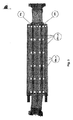
熱電モジュールは、p型及びn型の脚を備え、これらは、電気的に直列に、熱的に並列に接続されている。図2は、このようなモジュールを示すものである。 The thermoelectric module includes p-type and n-type legs, which are electrically connected in series and thermally in parallel. FIG. 2 shows such a module.
通常は、2つの支持プレートを有する構造であり、好適にはセラミックプレートであり、2つのセラミックプレートの間に個々の脚が交互に配置された構成となっている。2つの脚はそれぞれ、端面を介して電気的接点に導通可能に接続されている。 Usually, the structure has two support plates, preferably a ceramic plate, and has a structure in which individual legs are alternately arranged between the two ceramic plates. Each of the two legs is connected to the electrical contact through the end face so as to be conductive.
導電接触手段とは別に、実際の材料には通常、種々の付加的な層が施与される。これらの層は、保護層または接合層として機能する。しかし、最終的には、2つの脚の間に、金属ブリッジを介して電気的接触が確立される。 Apart from the conductive contact means, the actual material is usually provided with various additional layers. These layers function as a protective layer or a bonding layer. Eventually, however, electrical contact is established between the two legs via a metal bridge.
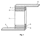
接触手段は、熱電素子の重要な要素である。接触手段は、素子の“中心”(素子の要求される熱電効果の要因になる)と“外界”との間の物理的接続を確立する材料である。このような接触手段の構成の詳細は図1に概略が示され、熱電モジュールの構造は図2に示されている。 The contact means is an important element of the thermoelectric element. The contact means is a material that establishes a physical connection between the “center” of the element (which contributes to the required thermoelectric effect of the element) and the “outside”. Details of the construction of such contact means are shown schematically in FIG. 1, and the structure of the thermoelectric module is shown in FIG.
素子内の熱電材料1は、素子の実際の効果の要因となる。これは熱電脚である。電流及び熱流は材料1を流下し、このために、全体構造におけるその目的が達成される。
The
材料1は、少なくとも両側部において、接点4及び5を介して供給線6及び7に接続されている。ここで、層2及び3は、材料1と接点4及び5との間で必要な1以上の中間層(バリア材料、はんだ、接着促進剤等)を表す。しかし、互いに対をなす層2/3、4/5、6/7は、同一のものでなくともよい。最終的には、同一であるかどうかは、構造を通過する電流または熱流の流下方向と同様に、最終的には特定の構造及び用途による。
The
接点4及び5には、重要な機能がある。これらは、材料と供給線との間の近接した接続を確保している。接点が脆弱であると高い損失が発生し、素子の性能が極めて制限されることとなってしまう。このため、脚及び接点はしばしば、材料に向かって圧接される。接点は、高い機械的負荷を受けることとなる。この機械的負荷は、温度の上昇(あるいは温度の低下)または/及び熱サイクルの回数が増えるにつれて増加する。素子に組み込まれる材料の熱膨張は、必然的に機械的負荷につながり、極端な場合は、接点の剥離による素子の破損へとつながることとなる。これを防ぐために、ある程度の柔軟性及び弾性を有する接点を使用することが理想的であり、これにより、熱的負荷が相殺され得る。
全体構造に安定性を与えるため、及び必要な、脚の全数に亘る実質的に均一な温度的組み合わせを確保するために、図2で示すようなサポートプレートが必要とされる。このため、セラミックが典型的に用いられる。セラミックは、例えば、Al2O3、SiO2またはAlNといった酸化物または窒化物から構成される。 A support plate as shown in FIG. 2 is required to provide stability to the overall structure and to ensure the necessary substantially uniform thermal combination over the entire number of legs. For this reason, ceramic is typically used. The ceramic is made of an oxide or nitride such as Al 2 O 3 , SiO 2 or AlN.
熱電モジュールを接触せしめられるのは平らな表面だけであることから、典型的な構造の使用に関しては制限がある。モジュールの表面と熱源/ヒートシンクとの間の近接した接触は、適切な熱の伝導を確保する観点からは不可欠である。 There is a limitation on the use of typical structures, since the thermoelectric module can only be brought into contact with a flat surface. Close contact between the module surface and the heat source / heat sink is essential from the standpoint of ensuring proper heat conduction.
近年、排気ガスの熱から電気的エネルギーを得るために、乗用車やトラックといった自動車の排気トレインまたは排気ガス循環システムに熱電モジュールを設ける試みがなされている。この場合、熱電素子の加熱側は排気ガスまたは排気管に晒される一方、冷却側は冷却システムに接続されている。発生せしめられる出力量は、排気ガスの温度、及び排気ガスから熱電材料への熱の流れに依存する。熱の流れを最大化するために、一般的に、排気管に継手が設けられている。しかし、例えば、一般的に、熱交換器を設けることは、内燃機関によるエネルギー消費の増大をもたらす許容しえないほどの排気ガス中の圧力損失を導くこととなることから、継手を設けるようなことには制限がある。 In recent years, in order to obtain electrical energy from the heat of exhaust gas, attempts have been made to provide a thermoelectric module in an exhaust train or exhaust gas circulation system of an automobile such as a passenger car or a truck. In this case, the heating side of the thermoelectric element is exposed to the exhaust gas or the exhaust pipe, while the cooling side is connected to the cooling system. The amount of output generated depends on the temperature of the exhaust gas and the flow of heat from the exhaust gas to the thermoelectric material. In order to maximize the heat flow, a joint is typically provided in the exhaust pipe. However, for example, in general, providing a heat exchanger will lead to unacceptable pressure loss in the exhaust gas that results in increased energy consumption by the internal combustion engine, so that a fitting is provided. There are limitations.
実際には、熱電発生器は通常、排気触媒コンバータの後ろの排気トレインに設けられている。排気触媒コンバータ中の圧力損失に伴って、結果として過剰な圧力損失が生じることから、排気管の外側を支持する熱電モジュールを有する排気トレインに、熱伝達継手は設けられていない。このため、一般的に、排気管は角を有する断面形状であることが必要であり、平面の外表面が熱電材料に近接する。しかし、これまでのところ、熱伝達は満足のいくものではなかった。 In practice, the thermoelectric generator is usually provided in the exhaust train behind the exhaust catalytic converter. A heat transfer joint is not provided in the exhaust train having the thermoelectric module that supports the outside of the exhaust pipe because an excessive pressure loss results as a result of the pressure loss in the exhaust catalytic converter. For this reason, in general, the exhaust pipe needs to have a corner cross-sectional shape, and the outer surface of the plane is close to the thermoelectric material. So far, however, heat transfer has not been satisfactory.
本発明は、上記課題に鑑みてなされたものであり、その目的は、熱電発電機の作動中に可能な限り大きな温度差を発生させることができる内燃エンジン用の排気トレイン中の熱電発電機の配置構造を提供することにある。特に、排気ガスから熱電発電機への熱伝達を改善することを目的とするものである。 The present invention has been made in view of the above problems, and its object is to provide a thermoelectric generator in an exhaust train for an internal combustion engine that can generate as large a temperature difference as possible during operation of the thermoelectric generator. It is to provide an arrangement structure. In particular, it aims to improve the heat transfer from the exhaust gas to the thermoelectric generator.
本発明によれば、上記目的は、集積された熱電発電機を有する内燃エンジン用の排気トレインによって達成され、排気トレインは、排気ガスを流下する少なくとも1のダクト、及び加熱側が排気ガスに直接接触する一方で冷却側が熱伝達媒体によって冷却される少なくとも1の熱電モジュールを備える。 According to the present invention, the above object is achieved by an exhaust train for an internal combustion engine having an integrated thermoelectric generator, the exhaust train being in direct contact with the exhaust gas, at least one duct flowing down the exhaust gas, and the heating side. While the cooling side comprises at least one thermoelectric module cooled by a heat transfer medium.
少なくとも1の熱電モジュールは、好適にはp型及びn型の脚を備え、これらは電気的には直列に、熱的には並列に接続されており、接触手段は、熱電モジュールの加熱側の支持プレート及び冷却側の支持プレートに対して支持され、排気ガス流は、熱電モジュールの加熱側の支持プレートに直接的に衝突する。 The at least one thermoelectric module preferably comprises p-type and n-type legs, which are electrically connected in series and thermally in parallel, the contact means being on the heating side of the thermoelectric module. Supported by the support plate and the support plate on the cooling side, the exhaust gas flow directly impinges on the support plate on the heating side of the thermoelectric module.
加熱側における排気ガスから熱電モジュールへの熱伝達及び冷却側における熱電モジュールから冷却媒体への熱伝達は、熱電モジュールにおいて可能な限り大きな温度差を与えるために重要である。 The heat transfer from the exhaust gas to the thermoelectric module on the heating side and the heat transfer from the thermoelectric module to the cooling medium on the cooling side are important in order to give the greatest possible temperature difference in the thermoelectric module.
広い意味において、本発明は、熱電発電機による熱エネルギーから電気的エネルギーへの直接的な変換によって排気ガス熱を活用することに関する。熱電発電機は、熱源(排気ガス)、熱電的アクティブモジュール及びヒートシンク(冷却媒体)からなる。電気的エネルギーを多く生み出すためには、熱源とヒートシンクとの間の可能な限りの大きな温度差、及び高効率の熱電モジュールを要する。 In a broad sense, the present invention relates to utilizing exhaust gas heat by direct conversion of thermal energy into electrical energy by a thermoelectric generator. The thermoelectric generator includes a heat source (exhaust gas), a thermoelectric active module, and a heat sink (cooling medium). In order to generate a lot of electrical energy, the greatest possible temperature difference between the heat source and the heat sink and a highly efficient thermoelectric module are required.
本発明は、排気ガスから熱電モジュールへの熱伝達が改善された熱電発電機に関し、この改善は、熱電的アクティブ要素の配置によって、及び/または必要な接触によって及び排気ガスを搬送するダクトの層を直接的に断熱することによって達成される。 The present invention relates to a thermoelectric generator with improved heat transfer from the exhaust gas to the thermoelectric module, which improvement is due to the arrangement of the thermoelectric active elements and / or through the required contact and the layer of the duct carrying the exhaust gas. This is achieved by directly insulating.
本発明による排気トレインは、熱電モジュールがカプセル状で挿入される開口部を有し、カプセル状の熱電モジュールが排気ガスと直接的に接触することが確保される。用いられるカプセル化された熱電モジュールは、冷却側の排気トレインに対して気密的に取り付けられる。 The exhaust train according to the present invention has an opening through which the thermoelectric module is inserted in a capsule shape, and it is ensured that the capsule thermoelectric module is in direct contact with the exhaust gas. The encapsulated thermoelectric module used is hermetically attached to the cooling side exhaust train.
発明の詳細な説明の導入部分及び図1及び図2で説明したように、熱電モジュールが構成される。 A thermoelectric module is constructed as described in the introduction part of the detailed description of the invention and in FIGS.
熱電モジュールの加熱側が排気ガスに直接的に接触するという状態によって、熱電モジュールの加熱側で損失する熱伝達が最小化される。対照的に、公知の実施の形態に係る熱電モジュールは、排気管の外側に配置されることから、熱伝達が著しく損なわれる。 The state where the heating side of the thermoelectric module is in direct contact with the exhaust gas minimizes heat transfer lost on the heating side of the thermoelectric module. In contrast, since the thermoelectric module according to the known embodiment is arranged outside the exhaust pipe, heat transfer is significantly impaired.
一般的に、熱電モジュールは、熱電モジュールに構造の安定性を付与し、かつ必要な熱的組み合わせを確保して、全ての脚部に亘って可能な限り均一とすべく、その表面上に支持体または断熱プレートを有する。 In general, a thermoelectric module is supported on its surface to give structural stability to the thermoelectric module and to ensure the necessary thermal combination and be as uniform as possible across all legs. With body or insulation plate.
本発明によれば、排気ガスから熱電モジュールへの熱伝達を大幅に妨げない限りにおいて、支持プレートに、付加的な保護層を設けることができる。たとえば、薄いシート状の金属層の被覆を施すことができる。 According to the present invention, an additional protective layer can be provided on the support plate as long as heat transfer from the exhaust gas to the thermoelectric module is not significantly hindered. For example, a thin sheet metal layer can be coated.
本発明によれば、“排気トレイン”の語は、内燃エンジンの排気ラインの部分を表す語として用いられている。しかし、排気トレインは、内燃エンジンのシリンダの出口から始まって排気管の出口までの全体部分を指す語としても用いられる。例えば、排気触媒コンバータ、及び排気ターボチャージャまたは微粒子フィルタ類といった他の部品を、排気トレインに付加的に設けることも可能である。本発明に係る排気トレインは、内燃エンジンの出口に可能な限り近接して設けられることで、熱電材料における高い温度差が許容される。排気トレインの正確な位置決めは、それぞれの熱電材料の安定性及び動作条件に依拠せしめることが可能である。 In accordance with the present invention, the term “exhaust train” is used as a term for an exhaust line portion of an internal combustion engine. However, the exhaust train is also used as a term referring to the entire part starting from the outlet of the cylinder of the internal combustion engine to the outlet of the exhaust pipe. For example, other components such as an exhaust catalytic converter and an exhaust turbocharger or particulate filters can be additionally provided in the exhaust train. The exhaust train according to the present invention is provided as close as possible to the outlet of the internal combustion engine, so that a high temperature difference in the thermoelectric material is allowed. The exact positioning of the exhaust train can depend on the stability and operating conditions of the respective thermoelectric material.
本発明に係る排気トレインは、排気ガスが流下しかつ熱電モジュールが配置された少なくとも1つのダクトを備える。実施例によれば、排気ガスは、複数のダクトに分配され、これらのダクトにはそれぞれ、熱電モジュールが設けられている。熱電モジュールが配置された近接したダクトは、例えば、冷却側において熱伝達媒体と接触する接点を共通して有する。 The exhaust train according to the present invention includes at least one duct through which exhaust gas flows and a thermoelectric module is disposed. According to an embodiment, the exhaust gas is distributed into a plurality of ducts, each of which is provided with a thermoelectric module. Adjacent ducts in which the thermoelectric modules are arranged have in common a contact that contacts the heat transfer medium on the cooling side, for example.
この配置では、ダクトは、任意の好適な横断面及び縦断面を採り得る。排気ガスを流下する少なくとも1つのダクトは、好適には、ほぼ平坦な側壁を有する矩形または台形の横断面を有し、1以上の平坦な側壁に熱電発電機が設けられる。例えば、熱電モジュールは、ダクトの対向する側壁に設けられる。熱電モジュールが設けられる領域では、排気トレインは、好適にはほぼ平坦な立体形状を有し、立体形状の平坦な側部すなわち最も広い表面領域には、熱電モジュールまたは発電機が配置される。 In this arrangement, the duct may take any suitable cross section and longitudinal section. The at least one duct through which the exhaust gas flows preferably has a rectangular or trapezoidal cross section with a substantially flat side wall, and a thermoelectric generator is provided on the one or more flat side walls. For example, the thermoelectric module is provided on the opposite side wall of the duct. In the region where the thermoelectric module is provided, the exhaust train preferably has a substantially flat three-dimensional shape, and a thermoelectric module or a generator is arranged on the flat side of the three-dimensional shape, ie the widest surface area.
本発明に係る排気トレインには、好適には、3〜100の熱電モジュールが配置されている。好適には2〜10、特に好適には3〜5の熱電モジュールの層が、排気ダクトに存在する。 The exhaust train according to the present invention is preferably provided with 3 to 100 thermoelectric modules. Preferably 2 to 10, particularly preferably 3 to 5, layers of thermoelectric modules are present in the exhaust duct.
同仕様の複数の熱電モジュールの熱電構造が用いられ、熱電発電機が互いに連結されていることが好適である。 It is preferable that a thermoelectric structure of a plurality of thermoelectric modules having the same specifications is used and the thermoelectric generators are connected to each other.
排気ガスを搬送するダクトは、熱電的アクティブ要素及びこれらの必要な断熱かつ接触層の直接的な支持体として機能する。これにより、ガスダクトに位置して分離的にパッケージされた熱電モジュールを設ける必要がなくなる。 The duct carrying the exhaust gas serves as a direct support for the thermoelectric active elements and their necessary thermal insulation and contact layers. This eliminates the need for a separately packaged thermoelectric module located in the gas duct.
本発明によれば、熱の流れを阻止する、排気ダクトと熱電的アクティブ要素との間の熱電モジュールの気密パッケージ用の任意の層を設ける必要がない。少なくとも1の熱電モジュールが、少なくとも1の熱電モジュールの冷却側の少なくとも1のダクトに気密的に組み込まれている。“冷却”側かつ近接した要素に対してパッケージされかつ気密的にシールされた電気的アクティブ要素は、加熱側に開放された被覆によって実装される。結果として、排気ガスは、その進入が阻止されずに、熱電モジュールまたは材料の加熱側に接触する。 According to the present invention, there is no need to provide an optional layer for the hermetic package of the thermoelectric module between the exhaust duct and the thermoelectric active element that prevents heat flow. At least one thermoelectric module is hermetically incorporated in at least one duct on the cooling side of the at least one thermoelectric module. Electrically active elements that are packaged and hermetically sealed to the “cooling” side and adjacent elements are implemented by a coating that is open to the heating side. As a result, the exhaust gas contacts the thermoelectric module or the heated side of the material without being blocked from entering.
排気ガスが流下する排気トレインまたはダクトは、任意の好適な材料で構成される。ガスダクトは、好適にはシートメタル、鋳物材料、機械加工されたバルク材料、または高温に耐性を有して固体とすることができる他のバルク材料で構成される。 The exhaust train or duct through which the exhaust gas flows is composed of any suitable material. The gas duct is preferably composed of sheet metal, casting material, machined bulk material, or other bulk material that is resistant to high temperatures and can be solid.
それぞれのガスダクトは、好適には矩形または台形の横断面を備え、かつ同一構成の縦断面を備える。 Each gas duct preferably has a rectangular or trapezoidal cross section and has a longitudinal section of the same configuration.
電気的アクティブ要素は、加熱側に開放した、深絞り金属シートで形成されたパッケージに設けられ、加熱側に開放したパッケージは、溶接、はんだ付け、焼結、接着固定または任意の他の手法で達成される金属的結合によりガスダクトに対して、気密的にシールされる。 The electrically active element is provided in a package made of deep-drawn metal sheet open to the heating side, which can be welded, soldered, sintered, adhesively fixed or any other technique It is hermetically sealed against the gas duct due to the metallic connection achieved.
本発明によれば、少なくとも1以上のダクトは、少なくとも1の熱電モジュールに排気ガスが近接して流下することを改善する継手を有し得る。しかし、このような継手によっても、ダクト中の圧力損失を大幅に増大させることはない。排気ガス、より好適には本発明に係る排気トレインあるいは本発明に係るダクトを流下する内燃エンジンからの排気ガス類の圧力損失は、100mbarを超えることはなく、特に50mbarを超えることはない。このような圧力損失によっても、内燃エンジンによる燃料消費の増大をもたらすことはない。 In accordance with the present invention, the at least one or more ducts may have a joint that improves the exhaust gas flowing close to the at least one thermoelectric module. However, such a joint does not significantly increase the pressure loss in the duct. The pressure loss of the exhaust gases, more preferably the exhaust gases from the internal combustion engine flowing down the exhaust train according to the invention or the duct according to the invention does not exceed 100 mbar, in particular does not exceed 50 mbar. Such pressure loss does not lead to increased fuel consumption by the internal combustion engine.
複数の熱電モジュールは、互いに前後して及び/または互いに隣接して熱電発電機の1の平面上に配置される。 The plurality of thermoelectric modules are arranged on one plane of the thermoelectric generator before and / or after each other and / or adjacent to each other.
過剰な温度から保護する保護層を、熱電モジュールにさらに設けることができる。“相変換層”とも称されるこの層は、好適には、無機金属塩または250℃〜1700℃の融点を有する金属合金で構成される。好適な金属塩は、フッ化物類、塩化物類、臭化物類、ヨウ化物類、硫酸塩類、硝酸塩類、炭酸塩類、クロム酸塩類、モリブデン酸塩類、バナジウム酸塩類及びタングステン酸リチウム、タングステン酸ナトリウム、タングステン酸カリウム、タングステン酸ルビジウム、タングステン酸セシウム、タングステン酸カルシウム、タングステン酸ストロンチウム及びタングステン酸バリウムである。二重または三重の共融合物を形成するこの種の好適な塩類の混合物は、材料として用いられることが好適である。これらは、四重または五重の共融合物を形成する。 A protective layer can be further provided on the thermoelectric module to protect against excessive temperatures. This layer, also referred to as “phase conversion layer”, is preferably composed of an inorganic metal salt or a metal alloy having a melting point of 250 ° C. to 1700 ° C. Suitable metal salts include fluorides, chlorides, bromides, iodides, sulfates, nitrates, carbonates, chromates, molybdates, vanadates and lithium tungstate, sodium tungstate, Potassium tungstate, rubidium tungstate, cesium tungstate, calcium tungstate, strontium tungstate and barium tungstate. A mixture of such suitable salts forming a double or triple co-fusion is preferably used as the material. These form quadruple or quintuple co-fusions.
代替的な相変換材料としては、亜鉛、マグネシウム、アルミニウム、銅、カルシウム、シリコン、リン及びアンチモンといった金属から出発する二重、三重、四重または五重の共融合物を形成する金属合金及びその混合物を用いることが可能である。金属合金の融点は、200℃〜1800℃の範囲内である。 Alternative phase change materials include metal alloys that form double, triple, quadruple or quintuple fusions starting from metals such as zinc, magnesium, aluminum, copper, calcium, silicon, phosphorus and antimony and their It is possible to use a mixture. The melting point of the metal alloy is in the range of 200 ° C to 1800 ° C.
熱電モジュールは、特に、ニッケル、ジルコニウム、チタン、銀及び鉄を用いる場合、あるいはニッケル、クロミウム、鉄、ジルコニウム及び/またはチタンを基にした合金を用いる場合に、保護層によりカプセル化される。 Thermoelectric modules are encapsulated by a protective layer, especially when using nickel, zirconium, titanium, silver and iron, or when using alloys based on nickel, chromium, iron, zirconium and / or titanium.
本発明に係る1以上の熱電モジュールは、例えば直列に連結された内燃エンジンの排気トレインに集積される。熱電モジュールを、異なった熱電材料と連結することが可能である。一般的に、内燃エンジンからの排気ガスの温度範囲に適した任意の、好適な熱電材料を用いることができる。好適な熱電材料の例としては、スクッテルド鉱、CoSb3,RuPdSb6、TX6(ここでT=Co、Rh、Ir及びX=P、As)、Sb、X2Y8Z24(ここでX=ランタニド、アクチニド、アルカリ土類金属、アルカリ金属、Th、第IV族の要素)、TiNiSn、HfPdSn及び2種以上の金属からなる合金といった半ホイスラ化合物、Zn4Sb3、Sr8Ga16Ge30、Cs8Sn44、CoTeSb4といった包接化合物、NaXCoO2、CaCo4O9、Bi2Sr2Co2OySr2TiO4、Sr3Ti2O7、Sr4Ti3O10、R1−XMXCoO3(ここでR=希土類金属、M=アルカリ土類金属)といった酸化物、Srn+1TinO3n+1(nは整数)、YBa2Cu3O7−X、FeSi2、Mg2Si及びMn15Si26といった珪素化合物、B4C、CaB6といったホウ化物、Bi2Ce3及びこれらの誘導体、PbCe及びこの誘導体、アンチモン化亜鉛のようなアンチモン化物、Yb14MnSb4といったジントル相が挙げられる。
One or more thermoelectric modules according to the present invention are integrated, for example, in an exhaust train of an internal combustion engine connected in series. It is possible to connect the thermoelectric module with different thermoelectric materials. In general, any suitable thermoelectric material suitable for the temperature range of the exhaust gas from the internal combustion engine can be used. Examples of suitable thermoelectric materials include skutterudite, CoSb 3 , RuPdSb 6 , TX 6 (where T = Co, Rh, Ir and X = P, As), Sb, X 2 Y 8 Z 24 (where X = Lantanide, Actinide, Alkaline earth metal, Alkali metal, Th, Group IV element), TiNiSn, HfPdSn and semi-Whistler compounds such as alloys of two or more metals, Zn 4 Sb 3 , Sr 8 Ga 16 Ge 30 , Cs 8 Sn 44 , CoTeSb 4 inclusion compounds, Na X CoO 2 , CaCo 4 O 9 , Bi 2 Sr 2 Co 2 OySr 2 TiO 4 , Sr 3 Ti 2 O 7 , Sr 4 Ti 3 O 10 , R 1 -X M X CoO 3 oxides such (where R = rare earth metal, M = alkaline earth metal), Sr n + 1 Ti n O 3n + (N is an integer), YBa 2 Cu 3 O 7 -X,
本発明に係る排気トレインは、好適には、自動車両に搭載される。この場合、排気トレインは、主に、排気ガスの熱から発電する。 The exhaust train according to the present invention is preferably mounted on a motor vehicle. In this case, the exhaust train generates power mainly from the heat of the exhaust gas.
特に、本発明に係る排気トレインによれば、排気ガスと熱電モジュールとの間の熱伝達損失が最小化されるという利点を有し、これにより、発電効率が改善される。 In particular, the exhaust train according to the present invention has the advantage that heat transfer loss between the exhaust gas and the thermoelectric module is minimized, thereby improving the power generation efficiency.
本発明に係る排気トレインの具体的な実施の形態について、図を用いて説明する。
(実施例)
図3は、2つの排気ダクト(20a、20b)の積層配置を有する本発明に係る排気トレインの概略断面図である。熱電モジュール(21a…n)は、下流に配置された冷却プレート(23a、23b、23c)に連結されて直接的に設けられ、これによりガスダクトから導入された熱を順次放散させ、かつ熱電モジュールを交差する温度勾配をできる限り大きく維持することに用いられる。
A specific embodiment of an exhaust train according to the present invention will be described with reference to the drawings.
(Example)
FIG. 3 is a schematic cross-sectional view of an exhaust train according to the present invention having a stacked arrangement of two exhaust ducts (20a, 20b). The thermoelectric modules (21a... N) are directly connected to the cooling plates (23a, 23b, 23c) disposed downstream, thereby sequentially dissipating heat introduced from the gas duct, and the thermoelectric modules. Used to keep the intersecting temperature gradient as large as possible.
図から明らかなように、熱電モジュール(21a…n)は、排気ダクト(20a、20b)中の排気ガスに加熱側が直接的に接触する一方、熱電モジュールの冷却側は、熱交換媒体(冷却板22a、22b、22c)によって冷却される。 As is apparent from the figure, the thermoelectric modules (21a... N) are in direct contact with the exhaust gas in the exhaust ducts (20a, 20b) on the heating side, while the cooling side of the thermoelectric module is the heat exchange medium (cooling plate). 22a, 22b, 22c).
図3で示すように、それぞれの排気ダクトの上下には、5つの連続した熱電モジュールが設けられている。冷却板は、図3の左側で示した接続部を介して内外で連通する冷却媒体に接触される。 As shown in FIG. 3, five continuous thermoelectric modules are provided above and below each exhaust duct. The cooling plate is brought into contact with a cooling medium communicating inside and outside through the connection portion shown on the left side of FIG.
図4は、図3で概略的に示された排気トレインの上部からの概略斜視図である。断熱構造の背後に、冷却板(22a…c)及び熱電モジュール(21a…n)が配されたことは明らかである。 FIG. 4 is a schematic perspective view from the top of the exhaust train schematically shown in FIG. It is clear that cooling plates (22a ... c) and thermoelectric modules (21a ... n) are arranged behind the heat insulation structure.
熱電モジュールの電気的な接続は、冷却板の上部において確認することができる。 The electrical connection of the thermoelectric module can be confirmed at the top of the cold plate.
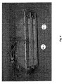
図5は、本発明に係る排気ダクト(20a/b)の構成を示しており、両側においてモジュールが装備されている。電気的入力及び出力を有する10の熱電モジュールが、示されている。 FIG. 5 shows the configuration of the exhaust duct (20a / b) according to the present invention, which is equipped with modules on both sides. Ten thermoelectric modules with electrical inputs and outputs are shown.
図示の排気トレインでは、排気ガスと熱電モジュールとの間の熱伝達損失が最小化され、これにより、発電生成の効率が改善される。 In the illustrated exhaust train, heat transfer losses between the exhaust gas and the thermoelectric module are minimized, thereby improving the efficiency of power generation.
Claims (7)
該熱電モジュールを構成する複数の熱電的アクティブ要素及びこれらの必要な断熱かつ接触層の直接的な支持体として機能し、排気ガスが流下する少なくとも1のダクトと、を備え、
前記複数の熱電的アクティブ要素は、前記ダクト内で加熱側が開放したパッケージに設けられており、該パッケージは前記ダクトに気密的にシールされ、
前記流下する排気ガスは、前記複数のアクティブ要素の加熱側に直接接触し、
少なくとも1の前記熱電モジュールには、過度な温度から保護する保護層が設けられており、
前記保護層は、融点が200℃〜1800℃の範囲内にある二重、三重、四重または五重の共融合物を形成する1種以上の金属合金及びその混合物を有することを特徴とする集積された熱電発電機を有する内燃エンジン用の排気トレイン。 At least one thermoelectric module arranged such that the heating side is in direct contact with the exhaust gas while the cooling side is cooled by the heat transfer medium;
A plurality of thermoelectric active elements constituting the thermoelectric module and at least one duct functioning as a direct support for these necessary thermal insulation and contact layers , through which exhaust gas flows,
The plurality of thermoelectric active elements are provided in a package open on the heating side in the duct, the package being hermetically sealed to the duct;
The exhaust gas flowing down directly contacts the heating side of the plurality of active elements ,
At least one of the thermoelectric modules is provided with a protective layer that protects against excessive temperatures,
The protective layer has one or more metal alloys that form a double, triple, quadruple, or quintuple fusion material having a melting point in the range of 200 ° C. to 1800 ° C. and a mixture thereof. An exhaust train for an internal combustion engine having an integrated thermoelectric generator.
該脚は電気的に直列かつ熱的に並列に接続され、且つ該個々の脚は2つの支持プレートの間に配置された構造を有し、
前記排気ガスは、前記熱電的アクティブ要素の加熱側の前記支持プレートに直接的に衝突することを特徴とする請求項1に記載の排気トレイン。 The plurality of thermoelectric active elements each comprise p-type and n-type legs;
The legs are electrically connected in series and thermally in parallel, and the individual legs have a structure disposed between two support plates;
The exhaust train of claim 1, wherein the exhaust gas directly impinges on the support plate on the heating side of the thermoelectric active element.
Applications Claiming Priority (3)
| Application Number | Priority Date | Filing Date | Title |
|---|---|---|---|
| EP11158782.0 | 2011-03-18 | ||
| EP11158782 | 2011-03-18 | ||
| PCT/IB2012/051264 WO2012127386A1 (en) | 2011-03-18 | 2012-03-16 | Exhaust train having an integrated thermoelectric generator |
Publications (3)
| Publication Number | Publication Date |
|---|---|
| JP2014515071A JP2014515071A (en) | 2014-06-26 |
| JP2014515071A5 JP2014515071A5 (en) | 2015-04-30 |
| JP6181560B2 true JP6181560B2 (en) | 2017-08-16 |
Family
ID=46878691
Family Applications (1)
| Application Number | Title | Priority Date | Filing Date |
|---|---|---|---|
| JP2013558560A Expired - Fee Related JP6181560B2 (en) | 2011-03-18 | 2012-03-16 | Exhaust train with integrated thermoelectric generator |
Country Status (7)
| Country | Link |
|---|---|
| US (1) | US9540982B2 (en) |
| EP (1) | EP2686531B1 (en) |
| JP (1) | JP6181560B2 (en) |
| KR (1) | KR20140020908A (en) |
| CN (1) | CN103502597B (en) |
| BR (1) | BR112013023753A2 (en) |
| WO (1) | WO2012127386A1 (en) |
Families Citing this family (9)
| Publication number | Priority date | Publication date | Assignee | Title |
|---|---|---|---|---|
| DE102012216042A1 (en) * | 2012-09-11 | 2014-03-13 | Friedrich Boysen Gmbh & Co. Kg | Device for converting thermal energy into electrical energy |
| DE102012219968A1 (en) * | 2012-10-31 | 2014-06-12 | Bayerische Motoren Werke Aktiengesellschaft | Exhaust system with thermoelectric generator |
| CN103427718B (en) * | 2013-07-24 | 2015-07-22 | 中国科学院电工研究所 | Train wheel set tread thermal radiation temperature difference generator |
| US10270985B2 (en) * | 2014-09-03 | 2019-04-23 | Intel Corporation | Augmentation of textual content with a digital scene |
| US9761781B2 (en) * | 2014-11-29 | 2017-09-12 | Hyundai Motor Company | Thermoelectric generator sleeve for a catalytic converter |
| CN104901585B (en) * | 2015-06-05 | 2017-06-20 | 华北水利水电大学 | The thermoelectric generating device and semiconductor generating equipment of a kind of utilization boiler back end ductwork fume afterheat |
| US10436087B2 (en) * | 2017-10-24 | 2019-10-08 | Ford Global Technologies, Llc | Heat exchanger for exhaust tuning systems |
| KR102310807B1 (en) * | 2018-01-23 | 2021-10-08 | 엘지이노텍 주식회사 | Thermoelectric element and method of preparating the same |
| KR101981629B1 (en) | 2018-01-23 | 2019-05-24 | 엘지이노텍 주식회사 | Thermoelectric element and method of preparating the same |
Family Cites Families (25)
| Publication number | Priority date | Publication date | Assignee | Title |
|---|---|---|---|---|
| JPS5827674B2 (en) | 1978-10-14 | 1983-06-10 | 日本碍子株式会社 | thermoelectric generator |
| US4463214A (en) * | 1982-03-16 | 1984-07-31 | Atlantic Richfield Company | Thermoelectric generator apparatus and operation method |
| JPH0448150Y2 (en) * | 1985-06-07 | 1992-11-12 | ||
| JP3676504B2 (en) * | 1996-07-26 | 2005-07-27 | 本田技研工業株式会社 | Thermoelectric module |
| US5968456A (en) * | 1997-05-09 | 1999-10-19 | Parise; Ronald J. | Thermoelectric catalytic power generator with preheat |
| US6385976B1 (en) * | 2000-09-08 | 2002-05-14 | Ferrotec (Usa) Corporation | Thermoelectric module with integrated heat exchanger and method of use |
| JP2003219671A (en) * | 2002-01-24 | 2003-07-31 | Komatsu Ltd | Thermoelectric power generation system |
| DE60310131T8 (en) * | 2002-12-26 | 2008-02-21 | Toyota Jidosha Kabushiki Kaisha, Toyota | DEVICE FOR GENERATING EXHAUST GAS |
| JP4165405B2 (en) * | 2003-10-06 | 2008-10-15 | トヨタ自動車株式会社 | Exhaust gas purification device |
| JP4423989B2 (en) | 2004-02-05 | 2010-03-03 | トヨタ自動車株式会社 | Thermoelectric generator for internal combustion engine |
| JP2005223132A (en) * | 2004-02-05 | 2005-08-18 | Toyota Motor Corp | Thermoelectric generator of internal combustion engine |
| JP4085998B2 (en) * | 2004-03-22 | 2008-05-14 | トヨタ自動車株式会社 | Waste heat recovery device |
| JP4305252B2 (en) * | 2004-04-02 | 2009-07-29 | 株式会社デンソー | Waste heat recovery device |
| JP2006266212A (en) * | 2005-03-25 | 2006-10-05 | Mazda Motor Corp | Exhaust heat power generation plant of internal combustion engine |
| CN1794557A (en) * | 2005-10-28 | 2006-06-28 | 刘万钊 | Engine exhaust pipe residual heat generating method and its device |
| JP5040124B2 (en) | 2006-03-01 | 2012-10-03 | トヨタ自動車株式会社 | Thermoelectric generator |
| US7287506B1 (en) * | 2006-09-13 | 2007-10-30 | Caterpillar Inc. | Thermoelectric system |
| DE102006057662A1 (en) * | 2006-12-07 | 2008-06-12 | Bayerische Motoren Werke Ag | Vehicle, has combustion engine and thermoelectric generator and heat exchanger has heating elements, which are arranged in exhaust gas channel of combustion engine and is pass or flow through exhaust gas |
| EP1965446B1 (en) * | 2007-02-28 | 2011-11-16 | Corning Incorporated | Glass-ceramic thermoelectric module |
| DE102008022802A1 (en) * | 2008-05-08 | 2009-11-19 | Benteler Automobiltechnik Gmbh | Device for generating electrical power from the waste heat of a motor vehicle internal combustion engine |
| DE102008023937A1 (en) * | 2008-05-16 | 2009-11-19 | Emitec Gesellschaft Für Emissionstechnologie Mbh | Device for generating electrical energy from exhaust heat |
| EP2180534B1 (en) * | 2008-10-27 | 2013-10-16 | Corning Incorporated | Energy conversion devices and methods |
| JP5268605B2 (en) * | 2008-12-05 | 2013-08-21 | 株式会社東芝 | Thermoelectric conversion device, thermoelectric power generation system, and thermoelectric power generation method |
| FR2957358B1 (en) * | 2010-03-12 | 2012-04-13 | Snecma | METHOD FOR MANUFACTURING THERMAL BARRIER PROTECTION AND MULTILAYER COATING FOR FORMING A THERMAL BARRIER |
| US8309044B2 (en) * | 2010-06-21 | 2012-11-13 | Corning Incorporated | Exhaust gas treatment system including a thermoelectric generator |
-
2012
- 2012-03-16 KR KR1020137024073A patent/KR20140020908A/en not_active Application Discontinuation
- 2012-03-16 US US14/004,477 patent/US9540982B2/en not_active Expired - Fee Related
- 2012-03-16 WO PCT/IB2012/051264 patent/WO2012127386A1/en active Application Filing
- 2012-03-16 JP JP2013558560A patent/JP6181560B2/en not_active Expired - Fee Related
- 2012-03-16 CN CN201280013398.1A patent/CN103502597B/en not_active Expired - Fee Related
- 2012-03-16 EP EP12760481.7A patent/EP2686531B1/en not_active Not-in-force
- 2012-03-16 BR BR112013023753A patent/BR112013023753A2/en not_active IP Right Cessation
Also Published As
| Publication number | Publication date |
|---|---|
| WO2012127386A1 (en) | 2012-09-27 |
| BR112013023753A2 (en) | 2016-12-06 |
| EP2686531A4 (en) | 2014-09-03 |
| KR20140020908A (en) | 2014-02-19 |
| US20140000249A1 (en) | 2014-01-02 |
| CN103502597B (en) | 2017-12-22 |
| US9540982B2 (en) | 2017-01-10 |
| EP2686531B1 (en) | 2016-10-12 |
| CN103502597A (en) | 2014-01-08 |
| JP2014515071A (en) | 2014-06-26 |
| EP2686531A1 (en) | 2014-01-22 |
Similar Documents
| Publication | Publication Date | Title |
|---|---|---|
| JP6181560B2 (en) | Exhaust train with integrated thermoelectric generator | |
| JP6129852B2 (en) | Exhaust system assembly | |
| KR101308257B1 (en) | Thermoelectric device | |
| US20170250334A1 (en) | Thermo-compression bonding of thermoelectric materials | |
| ES2439766T3 (en) | Thermoelectric device | |
| US9476617B2 (en) | Thermoelectric modules for an exhaust system | |
| US9728704B2 (en) | Thermoelectric module | |
| US10217923B2 (en) | Method for the production of a thermoelectric module | |
| JP6117102B2 (en) | Thermoelectric module for exhaust system | |
| US20130199590A1 (en) | Thermoelectric module for a thermoelectric generator of a vehicle with a sealing element and vehicle having the thermoelectric module | |
| TW201240173A (en) | Temperature protection of a thermoelectric module and/or of a thermoelectric generator using phase change materials | |
| KR20130128459A (en) | Thermoelectric module for a thermoelectric generator of a vehicle | |
| JP5902703B2 (en) | Thermoelectric module for vehicle thermoelectric generator | |
| TW201245569A (en) | Exhaust train having an integrated thermoelectric generator | |
| US20120073619A1 (en) | Temperature protection of a thermoelectric module and/or of a thermoelectric generator using phase change materials |
Legal Events
| Date | Code | Title | Description |
|---|---|---|---|
| A521 | Request for written amendment filed |
Free format text: JAPANESE INTERMEDIATE CODE: A523 Effective date: 20150313 |
|
| A621 | Written request for application examination |
Free format text: JAPANESE INTERMEDIATE CODE: A621 Effective date: 20150313 |
|
| A977 | Report on retrieval |
Free format text: JAPANESE INTERMEDIATE CODE: A971007 Effective date: 20151225 |
|
| A131 | Notification of reasons for refusal |
Free format text: JAPANESE INTERMEDIATE CODE: A131 Effective date: 20160105 |
|
| A601 | Written request for extension of time |
Free format text: JAPANESE INTERMEDIATE CODE: A601 Effective date: 20160331 |
|
| A521 | Request for written amendment filed |
Free format text: JAPANESE INTERMEDIATE CODE: A523 Effective date: 20160506 |
|
| A02 | Decision of refusal |
Free format text: JAPANESE INTERMEDIATE CODE: A02 Effective date: 20161011 |
|
| A521 | Request for written amendment filed |
Free format text: JAPANESE INTERMEDIATE CODE: A523 Effective date: 20170210 |
|
| A911 | Transfer to examiner for re-examination before appeal (zenchi) |
Free format text: JAPANESE INTERMEDIATE CODE: A911 Effective date: 20170501 |
|
| TRDD | Decision of grant or rejection written | ||
| A01 | Written decision to grant a patent or to grant a registration (utility model) |
Free format text: JAPANESE INTERMEDIATE CODE: A01 Effective date: 20170620 |
|
| A61 | First payment of annual fees (during grant procedure) |
Free format text: JAPANESE INTERMEDIATE CODE: A61 Effective date: 20170720 |
|
| R150 | Certificate of patent or registration of utility model |
Ref document number: 6181560 Country of ref document: JP Free format text: JAPANESE INTERMEDIATE CODE: R150 |
|
| LAPS | Cancellation because of no payment of annual fees |