JP4072217B2 - Surgical device and procedure to keep the heart stable during coronary bypass surgery - Google Patents
Surgical device and procedure to keep the heart stable during coronary bypass surgery Download PDFInfo
- Publication number
- JP4072217B2 JP4072217B2 JP07878097A JP7878097A JP4072217B2 JP 4072217 B2 JP4072217 B2 JP 4072217B2 JP 07878097 A JP07878097 A JP 07878097A JP 7878097 A JP7878097 A JP 7878097A JP 4072217 B2 JP4072217 B2 JP 4072217B2
- Authority
- JP
- Japan
- Prior art keywords
- contact member
- shaft
- heart
- contact
- shaft means
- Prior art date
- Legal status (The legal status is an assumption and is not a legal conclusion. Google has not performed a legal analysis and makes no representation as to the accuracy of the status listed.)
- Expired - Lifetime
Links
- 210000002216 heart Anatomy 0.000 title claims abstract description 332
- 238000000034 method Methods 0.000 title abstract description 86
- 238000001356 surgical procedure Methods 0.000 title abstract description 37
- 238000010009 beating Methods 0.000 claims abstract description 165
- 230000000087 stabilizing effect Effects 0.000 claims abstract description 165
- 230000033001 locomotion Effects 0.000 claims abstract description 42
- 230000006641 stabilisation Effects 0.000 claims description 61
- 238000011105 stabilization Methods 0.000 claims description 61
- 210000001367 artery Anatomy 0.000 claims description 58
- 230000007246 mechanism Effects 0.000 claims description 57
- 210000004351 coronary vessel Anatomy 0.000 claims description 37
- 239000000463 material Substances 0.000 claims description 17
- 238000003780 insertion Methods 0.000 claims description 16
- 230000037431 insertion Effects 0.000 claims description 16
- 230000008859 change Effects 0.000 claims description 6
- 239000003381 stabilizer Substances 0.000 claims description 5
- 239000008187 granular material Substances 0.000 claims description 4
- 230000000541 pulsatile effect Effects 0.000 claims description 4
- 238000003825 pressing Methods 0.000 claims description 3
- 238000005452 bending Methods 0.000 claims description 2
- 229920000642 polymer Polymers 0.000 claims description 2
- 238000013130 cardiovascular surgery Methods 0.000 claims 7
- 239000012212 insulator Substances 0.000 claims 1
- 230000003872 anastomosis Effects 0.000 abstract description 90
- 210000004165 myocardium Anatomy 0.000 abstract description 6
- 230000008602 contraction Effects 0.000 abstract description 3
- 210000004204 blood vessel Anatomy 0.000 description 65
- 210000001519 tissue Anatomy 0.000 description 64
- 238000010586 diagram Methods 0.000 description 29
- 239000012530 fluid Substances 0.000 description 26
- 230000008878 coupling Effects 0.000 description 20
- 238000010168 coupling process Methods 0.000 description 20
- 238000005859 coupling reaction Methods 0.000 description 20
- 230000017531 blood circulation Effects 0.000 description 19
- 229920001971 elastomer Polymers 0.000 description 16
- 210000000115 thoracic cavity Anatomy 0.000 description 14
- 230000008901 benefit Effects 0.000 description 13
- 230000009545 invasion Effects 0.000 description 13
- 230000006870 function Effects 0.000 description 11
- 239000008280 blood Substances 0.000 description 9
- 210000004369 blood Anatomy 0.000 description 9
- 230000002612 cardiopulmonary effect Effects 0.000 description 9
- 210000000038 chest Anatomy 0.000 description 9
- 210000001503 joint Anatomy 0.000 description 9
- 238000013461 design Methods 0.000 description 8
- 210000003516 pericardium Anatomy 0.000 description 8
- 238000013459 approach Methods 0.000 description 7
- 210000005003 heart tissue Anatomy 0.000 description 7
- 239000000017 hydrogel Substances 0.000 description 6
- 230000002829 reductive effect Effects 0.000 description 6
- 238000004804 winding Methods 0.000 description 6
- 208000002847 Surgical Wound Diseases 0.000 description 5
- 208000014674 injury Diseases 0.000 description 5
- 230000002441 reversible effect Effects 0.000 description 5
- 239000000126 substance Substances 0.000 description 5
- 230000008733 trauma Effects 0.000 description 5
- 230000000472 traumatic effect Effects 0.000 description 5
- 208000010496 Heart Arrest Diseases 0.000 description 4
- 238000004873 anchoring Methods 0.000 description 4
- 230000000747 cardiac effect Effects 0.000 description 4
- 239000011248 coating agent Substances 0.000 description 4
- 238000000576 coating method Methods 0.000 description 4
- 230000005484 gravity Effects 0.000 description 4
- 229910052751 metal Inorganic materials 0.000 description 4
- 239000002184 metal Substances 0.000 description 4
- 230000002093 peripheral effect Effects 0.000 description 4
- 210000000779 thoracic wall Anatomy 0.000 description 4
- 230000002792 vascular Effects 0.000 description 4
- 208000031104 Arterial Occlusive disease Diseases 0.000 description 3
- 230000009471 action Effects 0.000 description 3
- 208000021328 arterial occlusion Diseases 0.000 description 3
- 201000010099 disease Diseases 0.000 description 3
- 208000037265 diseases, disorders, signs and symptoms Diseases 0.000 description 3
- 230000010247 heart contraction Effects 0.000 description 3
- 210000001349 mammary artery Anatomy 0.000 description 3
- 230000013011 mating Effects 0.000 description 3
- 239000004033 plastic Substances 0.000 description 3
- 238000005096 rolling process Methods 0.000 description 3
- 229910001220 stainless steel Inorganic materials 0.000 description 3
- 239000010935 stainless steel Substances 0.000 description 3
- 230000001954 sterilising effect Effects 0.000 description 3
- 238000004659 sterilization and disinfection Methods 0.000 description 3
- 239000011324 bead Substances 0.000 description 2
- 230000036770 blood supply Effects 0.000 description 2
- 238000007664 blowing Methods 0.000 description 2
- 230000003139 buffering effect Effects 0.000 description 2
- 238000007675 cardiac surgery Methods 0.000 description 2
- 238000004891 communication Methods 0.000 description 2
- 230000006835 compression Effects 0.000 description 2
- 238000007906 compression Methods 0.000 description 2
- 230000000694 effects Effects 0.000 description 2
- 239000000806 elastomer Substances 0.000 description 2
- 230000006872 improvement Effects 0.000 description 2
- 239000007788 liquid Substances 0.000 description 2
- 230000014759 maintenance of location Effects 0.000 description 2
- 238000004519 manufacturing process Methods 0.000 description 2
- 230000036316 preload Effects 0.000 description 2
- 230000008569 process Effects 0.000 description 2
- 238000007789 sealing Methods 0.000 description 2
- 210000001562 sternum Anatomy 0.000 description 2
- 230000001629 suppression Effects 0.000 description 2
- 210000003462 vein Anatomy 0.000 description 2
- 230000000007 visual effect Effects 0.000 description 2
- 201000001320 Atherosclerosis Diseases 0.000 description 1
- 241001631457 Cannula Species 0.000 description 1
- 102000008186 Collagen Human genes 0.000 description 1
- 108010035532 Collagen Proteins 0.000 description 1
- 206010018852 Haematoma Diseases 0.000 description 1
- 206010052428 Wound Diseases 0.000 description 1
- 208000027418 Wounds and injury Diseases 0.000 description 1
- 229910052782 aluminium Inorganic materials 0.000 description 1
- XAGFODPZIPBFFR-UHFFFAOYSA-N aluminium Chemical compound [Al] XAGFODPZIPBFFR-UHFFFAOYSA-N 0.000 description 1
- 210000003484 anatomy Anatomy 0.000 description 1
- 210000002159 anterior chamber Anatomy 0.000 description 1
- 210000000709 aorta Anatomy 0.000 description 1
- QVGXLLKOCUKJST-UHFFFAOYSA-N atomic oxygen Chemical compound [O] QVGXLLKOCUKJST-UHFFFAOYSA-N 0.000 description 1
- 239000000560 biocompatible material Substances 0.000 description 1
- 230000000903 blocking effect Effects 0.000 description 1
- 210000003169 central nervous system Anatomy 0.000 description 1
- 238000003759 clinical diagnosis Methods 0.000 description 1
- 229920001436 collagen Polymers 0.000 description 1
- 230000000295 complement effect Effects 0.000 description 1
- 238000013016 damping Methods 0.000 description 1
- 229910003460 diamond Inorganic materials 0.000 description 1
- 239000010432 diamond Substances 0.000 description 1
- 238000006073 displacement reaction Methods 0.000 description 1
- 230000009977 dual effect Effects 0.000 description 1
- 210000002310 elbow joint Anatomy 0.000 description 1
- 229920006335 epoxy glue Polymers 0.000 description 1
- 210000004904 fingernail bed Anatomy 0.000 description 1
- 239000006260 foam Substances 0.000 description 1
- 239000007789 gas Substances 0.000 description 1
- 239000000499 gel Substances 0.000 description 1
- 238000010438 heat treatment Methods 0.000 description 1
- 229910052588 hydroxylapatite Inorganic materials 0.000 description 1
- 238000002513 implantation Methods 0.000 description 1
- 238000009434 installation Methods 0.000 description 1
- 238000005304 joining Methods 0.000 description 1
- 230000000670 limiting effect Effects 0.000 description 1
- 230000005389 magnetism Effects 0.000 description 1
- 230000006386 memory function Effects 0.000 description 1
- 244000005700 microbiome Species 0.000 description 1
- 238000002324 minimally invasive surgery Methods 0.000 description 1
- 238000012986 modification Methods 0.000 description 1
- 230000004048 modification Effects 0.000 description 1
- 230000002107 myocardial effect Effects 0.000 description 1
- HLXZNVUGXRDIFK-UHFFFAOYSA-N nickel titanium Chemical compound [Ti].[Ti].[Ti].[Ti].[Ti].[Ti].[Ti].[Ti].[Ti].[Ti].[Ti].[Ni].[Ni].[Ni].[Ni].[Ni].[Ni].[Ni].[Ni].[Ni].[Ni].[Ni].[Ni].[Ni].[Ni] HLXZNVUGXRDIFK-UHFFFAOYSA-N 0.000 description 1
- 229910001000 nickel titanium Inorganic materials 0.000 description 1
- 231100000252 nontoxic Toxicity 0.000 description 1
- 230000003000 nontoxic effect Effects 0.000 description 1
- 239000013307 optical fiber Substances 0.000 description 1
- 210000000056 organ Anatomy 0.000 description 1
- 239000001301 oxygen Substances 0.000 description 1
- 229910052760 oxygen Inorganic materials 0.000 description 1
- 230000036961 partial effect Effects 0.000 description 1
- 239000011236 particulate material Substances 0.000 description 1
- 230000000149 penetrating effect Effects 0.000 description 1
- XYJRXVWERLGGKC-UHFFFAOYSA-D pentacalcium;hydroxide;triphosphate Chemical compound [OH-].[Ca+2].[Ca+2].[Ca+2].[Ca+2].[Ca+2].[O-]P([O-])([O-])=O.[O-]P([O-])([O-])=O.[O-]P([O-])([O-])=O XYJRXVWERLGGKC-UHFFFAOYSA-D 0.000 description 1
- 230000004962 physiological condition Effects 0.000 description 1
- 230000009467 reduction Effects 0.000 description 1
- 230000003252 repetitive effect Effects 0.000 description 1
- 238000002271 resection Methods 0.000 description 1
- 230000000452 restraining effect Effects 0.000 description 1
- 230000000717 retained effect Effects 0.000 description 1
- 238000010008 shearing Methods 0.000 description 1
- 229920000260 silastic Polymers 0.000 description 1
- 239000007787 solid Substances 0.000 description 1
- 239000000758 substrate Substances 0.000 description 1
- 230000002861 ventricular Effects 0.000 description 1
Images


Classifications
-
- A—HUMAN NECESSITIES
- A61—MEDICAL OR VETERINARY SCIENCE; HYGIENE
- A61B—DIAGNOSIS; SURGERY; IDENTIFICATION
- A61B17/00—Surgical instruments, devices or methods, e.g. tourniquets
- A61B17/34—Trocars; Puncturing needles
- A61B17/3417—Details of tips or shafts, e.g. grooves, expandable, bendable; Multiple coaxial sliding cannulas, e.g. for dilating
- A61B17/3421—Cannulas
-
- A—HUMAN NECESSITIES
- A61—MEDICAL OR VETERINARY SCIENCE; HYGIENE
- A61B—DIAGNOSIS; SURGERY; IDENTIFICATION
- A61B17/00—Surgical instruments, devices or methods, e.g. tourniquets
- A61B17/00234—Surgical instruments, devices or methods, e.g. tourniquets for minimally invasive surgery
-
- A—HUMAN NECESSITIES
- A61—MEDICAL OR VETERINARY SCIENCE; HYGIENE
- A61B—DIAGNOSIS; SURGERY; IDENTIFICATION
- A61B17/00—Surgical instruments, devices or methods, e.g. tourniquets
- A61B17/02—Surgical instruments, devices or methods, e.g. tourniquets for holding wounds open; Tractors
- A61B17/0206—Surgical instruments, devices or methods, e.g. tourniquets for holding wounds open; Tractors with antagonistic arms as supports for retractor elements
-
- A—HUMAN NECESSITIES
- A61—MEDICAL OR VETERINARY SCIENCE; HYGIENE
- A61B—DIAGNOSIS; SURGERY; IDENTIFICATION
- A61B17/00—Surgical instruments, devices or methods, e.g. tourniquets
- A61B17/02—Surgical instruments, devices or methods, e.g. tourniquets for holding wounds open; Tractors
- A61B17/0218—Surgical instruments, devices or methods, e.g. tourniquets for holding wounds open; Tractors for minimally invasive surgery
-
- A—HUMAN NECESSITIES
- A61—MEDICAL OR VETERINARY SCIENCE; HYGIENE
- A61B—DIAGNOSIS; SURGERY; IDENTIFICATION
- A61B17/00—Surgical instruments, devices or methods, e.g. tourniquets
- A61B17/34—Trocars; Puncturing needles
- A61B17/3417—Details of tips or shafts, e.g. grooves, expandable, bendable; Multiple coaxial sliding cannulas, e.g. for dilating
- A61B17/3421—Cannulas
- A61B17/3423—Access ports, e.g. toroid shape introducers for instruments or hands
-
- A—HUMAN NECESSITIES
- A61—MEDICAL OR VETERINARY SCIENCE; HYGIENE
- A61B—DIAGNOSIS; SURGERY; IDENTIFICATION
- A61B90/00—Instruments, implements or accessories specially adapted for surgery or diagnosis and not covered by any of the groups A61B1/00 - A61B50/00, e.g. for luxation treatment or for protecting wound edges
-
- A—HUMAN NECESSITIES
- A61—MEDICAL OR VETERINARY SCIENCE; HYGIENE
- A61B—DIAGNOSIS; SURGERY; IDENTIFICATION
- A61B17/00—Surgical instruments, devices or methods, e.g. tourniquets
- A61B17/02—Surgical instruments, devices or methods, e.g. tourniquets for holding wounds open; Tractors
-
- A—HUMAN NECESSITIES
- A61—MEDICAL OR VETERINARY SCIENCE; HYGIENE
- A61B—DIAGNOSIS; SURGERY; IDENTIFICATION
- A61B17/00—Surgical instruments, devices or methods, e.g. tourniquets
- A61B17/064—Surgical staples, i.e. penetrating the tissue
- A61B17/0642—Surgical staples, i.e. penetrating the tissue for bones, e.g. for osteosynthesis or connecting tendon to bone
-
- A—HUMAN NECESSITIES
- A61—MEDICAL OR VETERINARY SCIENCE; HYGIENE
- A61B—DIAGNOSIS; SURGERY; IDENTIFICATION
- A61B17/00—Surgical instruments, devices or methods, e.g. tourniquets
- A61B17/12—Surgical instruments, devices or methods, e.g. tourniquets for ligaturing or otherwise compressing tubular parts of the body, e.g. blood vessels, umbilical cord
-
- A—HUMAN NECESSITIES
- A61—MEDICAL OR VETERINARY SCIENCE; HYGIENE
- A61B—DIAGNOSIS; SURGERY; IDENTIFICATION
- A61B17/00—Surgical instruments, devices or methods, e.g. tourniquets
- A61B17/56—Surgical instruments or methods for treatment of bones or joints; Devices specially adapted therefor
- A61B17/58—Surgical instruments or methods for treatment of bones or joints; Devices specially adapted therefor for osteosynthesis, e.g. bone plates, screws, setting implements or the like
- A61B17/68—Internal fixation devices, including fasteners and spinal fixators, even if a part thereof projects from the skin
- A61B17/80—Cortical plates, i.e. bone plates; Instruments for holding or positioning cortical plates, or for compressing bones attached to cortical plates
- A61B17/8061—Cortical plates, i.e. bone plates; Instruments for holding or positioning cortical plates, or for compressing bones attached to cortical plates specially adapted for particular bones
- A61B17/8076—Cortical plates, i.e. bone plates; Instruments for holding or positioning cortical plates, or for compressing bones attached to cortical plates specially adapted for particular bones for the ribs or the sternum
-
- A—HUMAN NECESSITIES
- A61—MEDICAL OR VETERINARY SCIENCE; HYGIENE
- A61B—DIAGNOSIS; SURGERY; IDENTIFICATION
- A61B17/00—Surgical instruments, devices or methods, e.g. tourniquets
- A61B17/00234—Surgical instruments, devices or methods, e.g. tourniquets for minimally invasive surgery
- A61B2017/00238—Type of minimally invasive operation
- A61B2017/00243—Type of minimally invasive operation cardiac
-
- A—HUMAN NECESSITIES
- A61—MEDICAL OR VETERINARY SCIENCE; HYGIENE
- A61B—DIAGNOSIS; SURGERY; IDENTIFICATION
- A61B17/00—Surgical instruments, devices or methods, e.g. tourniquets
- A61B2017/00535—Surgical instruments, devices or methods, e.g. tourniquets pneumatically or hydraulically operated
- A61B2017/00539—Surgical instruments, devices or methods, e.g. tourniquets pneumatically or hydraulically operated hydraulically
-
- A—HUMAN NECESSITIES
- A61—MEDICAL OR VETERINARY SCIENCE; HYGIENE
- A61B—DIAGNOSIS; SURGERY; IDENTIFICATION
- A61B17/00—Surgical instruments, devices or methods, e.g. tourniquets
- A61B2017/00681—Aspects not otherwise provided for
- A61B2017/00694—Aspects not otherwise provided for with means correcting for movement of or for synchronisation with the body
- A61B2017/00703—Aspects not otherwise provided for with means correcting for movement of or for synchronisation with the body correcting for movement of heart, e.g. ECG-triggered
-
- A—HUMAN NECESSITIES
- A61—MEDICAL OR VETERINARY SCIENCE; HYGIENE
- A61B—DIAGNOSIS; SURGERY; IDENTIFICATION
- A61B17/00—Surgical instruments, devices or methods, e.g. tourniquets
- A61B2017/00831—Material properties
- A61B2017/00858—Material properties high friction or non-slip
-
- A—HUMAN NECESSITIES
- A61—MEDICAL OR VETERINARY SCIENCE; HYGIENE
- A61B—DIAGNOSIS; SURGERY; IDENTIFICATION
- A61B17/00—Surgical instruments, devices or methods, e.g. tourniquets
- A61B2017/00982—General structural features
- A61B2017/00991—Telescopic means
-
- A—HUMAN NECESSITIES
- A61—MEDICAL OR VETERINARY SCIENCE; HYGIENE
- A61B—DIAGNOSIS; SURGERY; IDENTIFICATION
- A61B17/00—Surgical instruments, devices or methods, e.g. tourniquets
- A61B17/02—Surgical instruments, devices or methods, e.g. tourniquets for holding wounds open; Tractors
- A61B2017/0237—Surgical instruments, devices or methods, e.g. tourniquets for holding wounds open; Tractors for heart surgery
- A61B2017/0243—Surgical instruments, devices or methods, e.g. tourniquets for holding wounds open; Tractors for heart surgery for immobilizing local areas of the heart, e.g. while it beats
-
- A—HUMAN NECESSITIES
- A61—MEDICAL OR VETERINARY SCIENCE; HYGIENE
- A61B—DIAGNOSIS; SURGERY; IDENTIFICATION
- A61B17/00—Surgical instruments, devices or methods, e.g. tourniquets
- A61B17/064—Surgical staples, i.e. penetrating the tissue
- A61B2017/0647—Surgical staples, i.e. penetrating the tissue having one single leg, e.g. tacks
- A61B2017/0648—Surgical staples, i.e. penetrating the tissue having one single leg, e.g. tacks threaded, e.g. tacks with a screw thread
-
- A—HUMAN NECESSITIES
- A61—MEDICAL OR VETERINARY SCIENCE; HYGIENE
- A61B—DIAGNOSIS; SURGERY; IDENTIFICATION
- A61B17/00—Surgical instruments, devices or methods, e.g. tourniquets
- A61B17/11—Surgical instruments, devices or methods, e.g. tourniquets for performing anastomosis; Buttons for anastomosis
- A61B2017/1139—Side-to-side connections, e.g. shunt or X-connections
-
- A—HUMAN NECESSITIES
- A61—MEDICAL OR VETERINARY SCIENCE; HYGIENE
- A61B—DIAGNOSIS; SURGERY; IDENTIFICATION
- A61B17/00—Surgical instruments, devices or methods, e.g. tourniquets
- A61B17/28—Surgical forceps
- A61B17/2812—Surgical forceps with a single pivotal connection
- A61B17/282—Jaws
- A61B2017/2825—Inserts of different material in jaws
-
- A—HUMAN NECESSITIES
- A61—MEDICAL OR VETERINARY SCIENCE; HYGIENE
- A61B—DIAGNOSIS; SURGERY; IDENTIFICATION
- A61B17/00—Surgical instruments, devices or methods, e.g. tourniquets
- A61B17/28—Surgical forceps
- A61B17/29—Forceps for use in minimally invasive surgery
- A61B17/2909—Handles
- A61B2017/2912—Handles transmission of forces to actuating rod or piston
- A61B2017/2913—Handles transmission of forces to actuating rod or piston cams or guiding means
-
- A—HUMAN NECESSITIES
- A61—MEDICAL OR VETERINARY SCIENCE; HYGIENE
- A61B—DIAGNOSIS; SURGERY; IDENTIFICATION
- A61B17/00—Surgical instruments, devices or methods, e.g. tourniquets
- A61B17/28—Surgical forceps
- A61B17/29—Forceps for use in minimally invasive surgery
- A61B2017/2926—Details of heads or jaws
- A61B2017/2927—Details of heads or jaws the angular position of the head being adjustable with respect to the shaft
- A61B2017/2929—Details of heads or jaws the angular position of the head being adjustable with respect to the shaft with a head rotatable about the longitudinal axis of the shaft
-
- A—HUMAN NECESSITIES
- A61—MEDICAL OR VETERINARY SCIENCE; HYGIENE
- A61B—DIAGNOSIS; SURGERY; IDENTIFICATION
- A61B17/00—Surgical instruments, devices or methods, e.g. tourniquets
- A61B17/30—Surgical pincettes without pivotal connections
- A61B2017/306—Surgical pincettes without pivotal connections holding by means of suction
-
- A—HUMAN NECESSITIES
- A61—MEDICAL OR VETERINARY SCIENCE; HYGIENE
- A61B—DIAGNOSIS; SURGERY; IDENTIFICATION
- A61B17/00—Surgical instruments, devices or methods, e.g. tourniquets
- A61B17/34—Trocars; Puncturing needles
- A61B2017/348—Means for supporting the trocar against the body or retaining the trocar inside the body
- A61B2017/3482—Means for supporting the trocar against the body or retaining the trocar inside the body inside
- A61B2017/349—Trocar with thread on outside
Landscapes
- Health & Medical Sciences (AREA)
- Surgery (AREA)
- Life Sciences & Earth Sciences (AREA)
- Medical Informatics (AREA)
- Animal Behavior & Ethology (AREA)
- Engineering & Computer Science (AREA)
- Biomedical Technology (AREA)
- Heart & Thoracic Surgery (AREA)
- Veterinary Medicine (AREA)
- Molecular Biology (AREA)
- Nuclear Medicine, Radiotherapy & Molecular Imaging (AREA)
- General Health & Medical Sciences (AREA)
- Public Health (AREA)
- Pathology (AREA)
- Oral & Maxillofacial Surgery (AREA)
- Surgical Instruments (AREA)
- Dental Preparations (AREA)
- Materials For Medical Uses (AREA)
Abstract
Description
【0001】
循環系の病気は、毎年何百万人もの人々を患わせ、世界中で主要な死亡原因となっている。こうした病気が社会に及ぼす被害は、人命の損失という点でも従来の外科的技術による患者の治療費という点でも甚大である。特によく見られる循環系疾患の形態は、心臓に血液を供給する循環系の臨界点で血流が抑制されるアテローム硬化またはその他の状態によって引き起こされる心臓への供給血量の減少である。多くの場合、こうした心臓への血流の遮断または抑制は、冠状動脈迂回(CABG)法として知られる外科的処置によって治療されており、この処置は、より一般的には「心臓バイパス」手術として知られている。CABG法では、外科医は、利用可能な源血管を閉塞された標的冠状動脈に取り付けるか、または身体の別の部分から静脈または動脈の一部分を切り取って移植片として使用し、この移植片を源血管と標的動脈との間の各地点に取り付けて正常な血流を回復させることにより、閉塞を「迂回」して心臓への正常な血流を回復させる。
【0002】
CABG法は、かなり一般的になってきたが、この処置そのものが冗長かつ外傷性であり、心臓、循環系、中枢神経系および血液供給そのものを損ないうる。従来のCABG法では、外科医は、胸部中央に縦方向に長い切開部を作り、胸骨を全長にわたって切開して、患者に心肺迂回装置を取り付けるのに必要なその他のいくつかの処置を行ない、心臓への血流を遮断し、次に心臓を拍動停止させて迂回手術を完遂しなければならない。最も冗長かつ外傷性の外科的処置は、ひとつには患者に心肺迂回(CPB)装置を接続して、迂回手術が完了するまで身体のその他の部分に酸素含有血を継続的に循環させるために必要とされる。
【0003】
CABG法における侵入と外傷とを軽度にするために幾つかの試みがなされてきたが、ほとんどの技術では、依然として心肺迂回(CPB)および心停止(心臓を停止させること)が必要になる。 CABG法の安全性および有効性は、処置時に外科医が心臓を拍動停止させる必要がなく、したがって心肺迂回と、患者に心肺迂回装置を接続して患者の生命を維持するのに必要な冗長かつ外傷性の外科的処置とを行なわなくてもよくなれば、向上しうる。近年、少数の外科医が、心臓を拍動させたままでCABG法を行ないうるように特別に開発された外科的技術を用いて、CABG法を実施し始めた。こうした処置では、いかなる形態の心肺迂回も必要とされず、患者に心肺迂回装置を接続するのに必要な広範な外科的処置を行なわなくてもよく、心臓を停止させる必要もない。その結果として、この手術は、侵入がはるかに軽度であり、全ての処置が、通常は一般に1箇所または2箇所である少数箇所の比較的小さい胸部切開部を介して遂行されうる。
【0004】
これらの利点にもかかわらず、心拍動式CABG法は、必要な外科的処置を従来の外科用装置を用いて行なうのが困難である等の理由で、幅広く実施されるには至っていない。CABG法を拍動している心臓に対して行ないうるように特別に設計された装置を利用することができれば、心拍動式CABG法は、さらに幅広く行なわれて、有為な患者数での循環器疾患の治療が改善されるであろう。
【0005】
上記のように、CABG法では、血流を回復させるための流体接続部を2点間で確立させて、患部または閉塞部を迂回して心臓への血流を回復させることが必要とされる。この処置は、「吻合術」として知られている。一般に、血流障害のない源動脈などの源血管である左内胸動脈(LIMA)または一端が大動脈などの障害のない源動脈に縫合される迂回用移植片は、心臓の筋肉に血流を供給する左前室間枝(LAD)またはその他の血管等の標的閉塞冠状動脈に縫合される。心拍動式CABG法は、心筋が収縮して血液を送出し続けている状態のままで行なわれるので、外科医が吻合部を縫合している間も心臓は動き続けるために、吻合処置を行なうのが困難となる。
【0006】
心拍動式CABG法において吻合部を創出する外科的処置の特定の部分では、心臓表面上の非常に細い血管に一連の縫合糸を通すことが必要であり、かつ処置中も心筋が拍動して血液を送り続けている状態で吻合を完成させることが必要である。さらにまた、これらの縫合糸の配置に注意して、源血管または移植片が、吻合完成時点でしっかりと取り付けられて、血管を通る血流が確立された時に漏出が起こらないようにしなければならない。また、過剰な血液損失を防ぐために標的冠状動脈を通る血流を一時的に遮断または減少させる場合があるため、吻合処置を迅速に行なうことも重要である。さらに、外科医は、胸部の小切開部を介して作業を行なう場合があり、または手術部位が外科用内視鏡を介して観察される場合はビデオモニターで処置を観察することもあるため、作業空間および視覚的アクセスが制限される。
【0007】
ある現行の実践方法では、外科医は、心臓の組織に縫合糸を通し、これらの縫合糸に逆向きの張力を加えることにより、吻合部位を取り巻く組織を伸長させて、心臓の動きを部分的に低下させながら吻合を完成させている。この方法は、理想にはほど遠い。これに代わる方法として、心臓の表面に吸引装置を取り付けて、表面組織の外層部の動きを固定することができる。このような場合には、吸引装置は、一般に複数の吸引口を、心臓に取り付けられて表面組織に負圧を加えうる装置に内蔵させて有する。この負圧は、実質的に表面組織を装置に付着させて、以て心臓の表面の一部分の位置を固定する。このような装置は、同時係属米国出願第603、328号で説明されている。
【0008】
負圧を用いる方法は、心臓の表面の一部分を固定するのには効果的であるかもしれないが、心臓の組織に加えられる負圧は、吸引口が組織に付着する部位で一時的な血腫を引き起こしうる。また、心臓の外側の組織は、装置の形状と吸引口の配向とによって限定される形状に固定される。心臓が拍動し続けている間、心筋は収縮して血液を送出しており、そのために、心筋は、吸引により固定された外側組織から離れようとする方向に力を発揮する。
【0009】
処置時に心臓を安定させて、たとえ心臓が拍動して身体に血液を供給し続けていても、特に吻合部位における心臓の動きが最小限に抑えられるようにすることができれば、心拍動式CABG法は大幅に改善されうる。拍動する心臓を安定させる効果的な手段を利用することができれば、心拍動式CABG法は、より容易かつより迅速かつより安全に実施され得、患者に与える外傷も軽減される。
【0010】
【課題を解決するための手段】
本発明の装置および技術が外科医に与える利点により、心拍動式CABG法をより迅速に実施することができ、患者に与える外傷も軽減され、外科医はCPBまたは心停止法を用いることなしにCABG法を実施することが可能になる。本発明は、外科的処置時に安定化力を心臓に加えて、拍動する心臓の動きを最小限に抑えるように特に設計された機械的装置を用いて心臓の動きを安定させる装置と方法とを提供することにより、吸引装置に代わる方法を実現する。本発明により、外科医は、容易かつ迅速に心拍動式CABG法を実施することができ、したがって心停止法または心肺迂回を行なう必要がなくなる。特に、本明細書で説明される方法および装置は、外科医が心臓を安定させることを可能にして、外科的処置の継続時間にわたって動きが最小限に抑えられる標的冠状動脈に、外科医が源血管または迂回用移植片を取り付けることによって吻合がより容易に達成されうるようにする。
【0011】
本発明によれば、安定化装置は、拍動する心臓への接近路となる胸部の適切な開口を通して導入される。本発明の拍動する心臓を安定させる手段を心臓に接触させ、心臓に安定化力を加えることによって、心筋の収縮により引き起こされる心臓の動きが効果的に解消されて、吻合部位の標的動脈の移動が最小限に抑えられるようになる。心臓のその他の部分は、正常に収縮していてもよく、またはさらに別の装置を設置して心臓を補助するか、心臓の動きを抑制してもよい。また、本発明の装置を複数個用いて、拍動する心臓を位置決めすることで、手術野を改善すること、心臓を手術するのに好適な状態に保つこと、または心臓を回転させて心臓の判明な特徴を外科医が視認可能かつ接近可能な手術野に提示することができる。
【0012】
本発明の重要な利点は、新規かつ効果的な技術を本明細書で説明し、かつ本発明の装置を用いて外科的に実施することで、拍動する心臓を外科的処置の際に安定させるかまたは位置決めする有利な技術が提供されうるという発見から導かれる。この拍動する心臓を安定させる処置は、通常的に本明細書で説明されるように構成される装置を用いて、拍動する心臓に安定化力を加えることを必要とする。一般的には、別々の段階で、外科医は、拍動する心臓を安定させる本発明の手段の少なくとも1つの構成要素を心臓に接触させ、特に手術部位における心臓の動きの程度を分析し、安定化手段の前記構成要素を吻合部の標的冠状動脈等の手術部位に隣接する位置に配置する。正位置にある安定化手段の機能部分により、外科医は、拍動する心臓に安定化力を加えて、心臓の表面と接触している装置の前記部分が心臓の表面を、心臓の収縮が手術部位において垂直方向または水平方向のいずれにも実質的な動きをも引き起こさなくなる距離だけ変位させるようにする。この安定化力は、本発明の安定化手段の少なくとも1つの構成要素を用いて直接的または間接的に加えられ、通常的に標的冠状動脈等の特定の部位で拍動する心臓に物理的な力を加えることおよび通常的に拍動する心臓の表面に対して垂直な方向に少なくとも部分的に付与される力を加えることからなる。このように、本発明の重要な態様は、本明細書で説明されるような特殊な設計の装置を用いて心臓の外側で特に手術部位に隣接する位置に作用する物理的な安定化力を加えることにより、外科的処置にあたって拍動する心臓を効果的に安定させうるという発見にある。この安定化力は、拍動する心臓が生じる動きに抗する力または心臓に加えられる付加的な力である安定化力で構成されうる。
【0013】
安定化手段の位置を拍動する心臓の動きが効果的に解消される状態に固定することにより、外科医は、処置の継続時間にわたって、この安定化力を拍動する心臓に対して維持する。拍動する心臓を安定させる手段の位置を固定するために、安定化手段は、肋骨を分離させるのに用いられる牽引子またはそれ以外の固定支持体に取り付けられうる。また、安定化手段は、機械的または化学的にあるいは人的介入により実質的に剛化される整合性または可撓性または半剛性のアームまたは軸手段に取り付けられてもよい。特定の好適な実施例では、安定化手段は、複数の方向に配向され得かつ牽引子に取り付けられるようになっている固定具を有する調節可能な軸手段を有する。本発明の好適な技術では、外科医は、最初に開胸術を行なって、牽引子を用いて肋骨を開き、次に、これらの肋骨を開いた状態で固定して、拍動する心臓への接近路を得ることができる。その後、外科医は、調節可能な軸を備えた安定化手段の構成要素を標的冠状動脈に隣接する地点で心臓の表面に接触させ、この手段に安定化力を加えて拍動する心臓を安定させる。調節可能な軸を操作することにより、手術部位は実質的に不動となる。拍動する心臓に接触する安定化手段の構成要素上の付着面または高摩擦面というまた別の特徴を用いると、この力を付与するのに有利であり、力の絶対量を最小限に抑えることができる。この地点で、調節可能な軸手段は、たとえば牽引子に安定的に取り付けられることにより位置固定されて、以て標的冠状動脈は処置の継続時間にわたって実質的に不動とされる。
【0014】
【発明の実施の形態】
本発明は、拍動する心臓を安定させる外科用装置および該装置の使用方法である。拍動する心臓を安定させる手段は、心臓の表面に係合して、拍動する心臓を冠状動脈手術時に安定させる少なくとも1つの構成要素を有する複数の異なる構造を具える。これらの装置は、心臓に安定化手段の構成要素を接触させ、外科的処置の継続時間にわたって安定化手段の位置を機能的に固定することにより、心臓に対して安定化力を加えかつ維持する機能を果たす。
【0015】
本発明の装置および方法は、たとえば迂回用移植片を取り付けることまたは源動脈を接続することにより、心停止法または線維攣縮等の心停止を必要とせずかつ心肺迂回(CPB)を用いることなしに吻合を容易に完成させるために特別に開発された、侵入を最小限に抑えた冠状動脈迂回(CABG)手術を標的冠状動脈に対して行なう際に心臓を安定させるのに用いられることが好適である。拍動する心臓を安定させる手段は、さまざまな外科的処置に適用されうるが、本明細書で説明される装置は、侵入を最小限に抑えた切開部が胸部に1ヵ所または2ヵ所だけ形成されるCABG法に用いるのが最も有利である。本発明の安定化手段の完全な構造は、侵入を最小限に抑えた外科的処置が実施されている時に拍動する心臓を安定させておく複数の実施例の構造のいずれで達成されるものであってもよい。安定化手段の別個の構成要素は、牽引子と、閉塞装置と、外科用送風器または吸引装置と、LIMA保持装置等の源動脈を保持する装置と、外科医がより効率的に吻合を完成させることを可能にするその他の同様の別個のまたは一体的な外科用機器または装置とを内蔵する多部品装置においても有利に機能しうる。本明細書に開示されるいずれの装置も、機械的な手段を用いて拍動する心臓を安定させるものであるが、一部の実施例は心臓全体に作用するように設計される一方で、その他の実施例は、より局所的な効果を有しており、吻合部の標的動脈等の構造に直接隣接する部位に適用されうる。いずれの場合も、拍動する心臓は、外科的処置が実施される部位で効果的に安定化される。
【0016】
拍動する心臓への手術路は、従来の心臓迂回手術用に開発された複数の慣例の外科的処置によって実現され得、そのために、外科医は、拍動する心臓に迂回路を取り付けるいかなる処置の場合も、心臓への接近路を確保する外科的方法にかかわりなく、本発明が提供する利点を得ることができる。外科医は、さらに他の方策により胸腔内で心臓全体の動きを抑制して、本明細書に開示される特定の実施例を用いて拍動する心臓を位置決めまたは配向することが好ましい。たとえば、膨張可能な緩衝体または細紐を取り付けられて有する調節可能な帯を心臓の下または周囲に挿入してもよい。拍動する心臓への接近路が胸骨切開術によって実現される場合は、胸骨の全長の少なくとも一部分を分断して心臓の表面を露出させる。また、心膜を利用することができる場合は、心膜を切開して、拍動する心臓を位置決めするのに利用してもよい。利用可能は場合には、外科医は、心膜を利用して拍動する心臓を胸腔内で持ち上げて回転させ、心膜を切開部の周縁部に縫合することによってその位置を維持することができる。
【0017】
好適な実施例では、拍動する心臓への、侵入を最小限に抑えた接近路は、通常的に胸部左側で肋骨間に小さめの切開部を形成することにより開胸部を創出した後に、肋骨間に牽引子を挿入して肋骨を開かせ、牽引子を開位置に固定して源血管および標的冠状動脈への接近路を得ることによって実現される。上記のように心膜を利用して拍動する心臓を位置決めすることは、侵入が軽減された開胸術を用いて心臓への接近路を得る場合に特に有利である。この処置では、心膜に切開部が創出されて、次に心膜が開胸部の周縁部に縫合される。この状態で、心膜は拘束袋の働きをして、拍動する心臓を、吻合を達成する上で望ましい配向に維持する。
【0018】
一旦心臓への接近路が実現され、必要に応じて心臓が位置決めされると、拍動する心臓を安定させる手段を、開胸術により創出された開口を通して導入して、本発明の安定化装置の少なくとも1つの構成要素を拍動する心臓に接触させる。次に、外科医は、安定化手段により、拍動する心臓に安定化力を加え、その後、安定化装置を固定支持体に取り付けることにより位置固定することができる。肋骨牽引子または牽引台を開位置に固定して心臓を露出させる場合には、牽引子台もまた、安定化装置を固定する安定な支持構造体となりうる。安定化手段の位置を安定支持体または牽引子台に取り付けることにより固定すると、安定化力が処置の継続時間にわたって維持される。
【0019】
特定の源血管と標的動脈との吻合は臨床的に判断されるが、拍動する心臓に対する侵入を最小限に抑えた通常的な迂回処置として、源動脈としての左内胸動脈(LIMA)と標的動脈としての左前室間枝(LAD)との間に接続部を形成させる吻合があげられる。本明細書ではLIMAとLADとの吻合を例にとるが、本明細書で説明される技術および装置は、臨床的診断に応じてその他の処置にも、また患者の解剖にも適用されうることが容易に理解される。吻合を完成させるためには、外科医は、LIMAの一部分を胸腔内部から取り出すことにより切除しなければならない。一旦LIMAの切除が達成されると、外科医は、切除されたLIMAを標的冠状動脈であるLADに取り付けることができる。本例においては、本発明の安定化手段は、少なくとも前記処置の一環として外科医がLIMAとLADとの吻合を完成させる時に、拍動する心臓を安定させるのに用いられる。
【0020】
心臓に接触する安定化装置の一部分の構造には、吻合部位に隣接する位置で心臓に安定化力を加える1つ以上の接触部材が含まれうる。1対の接触部材は、吻合部位において標的冠状動脈の両側に配置されかつ摩擦手段または組織伸張または収縮手段を付随して有しうる板または矩形部材であってもよい。これらの接触部材は、さらにまた、実質的に平面状であるかまたは心臓の表面に整合的に密着する外形を有する台であってもよい。また、安定化手段に、複数の異なる実施例を持つ軸手段を含ませて、装置の位置および配向を調節しやすくすることもできる。たとえば、この軸手段は、調節可能な長さを有していてもよく、軸手段の軸は、その全長内に配設されて接触部材または安定支持体等のその他の構造体に対する軸手段の配向を連続的に変化させうるような少なくとも1つの玉継手を有しうる。複数の実施例の説明から明らかなように、本明細書で説明されかつ図示される個別の実施例の各々は、本発明の範囲または精神から外れることなしに、その他の複数の実施例のいずれの特徴とも容易に切り離されることまたは組み合わされることができる別個の構成要素および特徴を有する。
【0021】
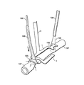
図1を参照すると、拍動する心臓を安定させる手段は、2つであることが好適な1つ以上の接触部材1を具えており、これらの接触部材は、剛性または半剛性の接続軸2に取り付けられ、この接続軸はさらに軸手段3に接続される。接触部材1は、実質的に平面状であってもよく、心臓の形状に整合するように若干湾曲していてもよく、または接触部材1の単なる一部分と拍動する心臓との間で接触が確立される非整合曲面であってもよい。接触部材1は、円筒部材、U字形に形成される部材を含む複数の異なる形状のいずれを有していてもよく、または互いに離間して標的動脈が接触部材間に配置されうるようにする1対の実質的に平行な部材を具えていてもよい。接触部材の形状は、外科医による臨床検査、安定化手段のその他の特徴の設計または吻合を完成させるのに用いられるその他の装置の設計に応じて変化しうる。一部の実施例では、本明細書で説明されるように、接触部材1は、縫合糸またはその他の装置との接続を容易にして、所要の安定化、標的血管の閉塞または標的血管の露出を達成する孔部、開口または付属物を有しうる。好適な実施例では、1対の実質的に平面状の矩形接触部材1が、一方の端部で連続的な接続軸2に取り付けられ、実質的に平行な態様に配向されて、安定化手段を心臓に係合させた時に標的心臓動脈が両者間に配置され、より長い接触部材1に沿って延在するようになっている。図164〜図166を参照されたい。接続軸2は、動脈に接触することなしに接触部材1を相互接続する連続軸であってもよく、または図98〜図103に示されるように接触部材1間に配置される標的動脈に接触して、標的動脈を通る血液の通路を閉塞させる働きをしうるさらに他の部材を含んでいてもよい。接触部材1、接続軸2および軸手段3は、軸手段3が操作されるかまたは固定されることで接触部材が拍動する心臓に対して安定化力を加えることにより心臓に加えられる安定化力に耐えうるだけの十分な引張り強度を有する生体適合性プラスチックまたはステンレス鋼等のいかなる非毒性材料により構成されてもよい。さらにまた、接触部材1の各々は一方の端部で接続軸2に接続され、この接続軸2は軸手段3に動作可能に取り付けられるが、本明細書で説明されかつ図示される接触部材の個別の実施例の各々は、当業者が異なる設計の軸手段等のその他の複数の実施例または本発明のその他の構成要素のいずれの特徴とも容易に切り離すことまたは組み合わせることが可能な別個の特徴を有する。
【0022】
軸手段3は、単純な剛性柱であってもよく、またはその全長沿いの少なくとも1地点で長さおよび配向を調節できるように設計される多部品システムを具えていてもよい。このようにすると、外科医は、軸手段3の長さと、軸手段3の遠位(下側)端部にある接触部材1の配向とを変化させることができる。接触部材1に対する軸手段3の長さおよび配向は、軸手段3の近位(上側)端部に配設される調節部により調節されうることが好ましい。(「遠位」という用語は、本明細書で使用される場合には、心臓に最も隣接する装置部分を表わす一方で、近位という用語は、切開部の外側に延在し得かつ大抵の場合に外科医が容易に操作しうる反対側部分を表わす。)この設計は、外科医が接触部材を心臓の表面上に配置することにより安定化手段を拍動する心臓に導入し、次に安定化力を加えることと接触手段1を軸手段3に対して位置固定することとを組み合わせて行なうことができるという利点を提供する。さらにまた、外科医は、その後、軸手段を牽引子などの安定支持体に取り付けることにより固定位置に固定して、以て処置の継続時間にわたって安定化力を維持することができる。ある実施例では、軸手段3は、ハウジング11を有しており、このハウジングの全体としての長さは、ハウジングのまわりで締め付けられる環状のつまみ8により操作される入れ子状解放装置によって調節される。軸手段3に対する接触部材1の位置および配向は、接続軸2の間に介在しかつ軸手段3の遠位端に配置される固定用玉継手5によって調節されうる。この固定用玉継手5は、軸手段3の位置を接触部材1に対して3つの自由度で位置決め可能にする。
【0023】
再び図1を参照すると、固定用玉継手5は、玉継手5に整合的に接触して玉継手5の位置を固定するブロック6を軸手段3内に含めることによって得られる。ブロック6は、長尺の入れ子状スプライン付き軸と軸収容体とを組み合わせたもの9に接続されるねじ付き押しブロック7を軸手段3の上端にあるつまみ8等の手段により作動させると、玉継手5に押し付けられる。操作時には、最上部のつまみ8を回転させることにより、下側玉継手5が緩められて、接触手段1に対して軸手段3を連続的に位置決めすることができ、逆回転により玉継手5は位置固定されて、接触部材1の位置が軸手段3に対して固定される。
【0024】
軸手段3の上端にも上側玉継手13を付随して設けて、軸手段3が牽引子等の固定支持体(図示せず)に対して4つの自由度で配向されうるようにしてもよい。軸手段3の位置および配向は、上側玉継手13の移動を防止する固定用ラッチ14またはその他の従来式機構により、このように安定支持体に対して固定されうる。軸手段3または牽引子のいずれに上側玉継手13を取り巻く固定用ラッチ14または何らかの同様の固定具を内蔵させて、軸手段3を、たとえば牽引子(図示せず)から延在する係止部分15である安定支持体に堅固に取り付けてもよい。
【0025】
図3〜図8を参照すると、接触部材1は、該接触部材の底面4に付随する摩擦手段を有しており、安定化力が軸手段3に加えられた時に接触部材1が、拍動する心臓に、より確実に係合するようになっていることが好ましい。この摩擦手段は、接触部材1の底面4を覆う凹凸加工面を具えることが好ましく、凹凸加工されたゴムや凹凸加工または中高加工されたアルミ、ステンレス鋼等の複数の生体適合性物質で構成されうる。
【0026】
摩擦手段は、さらにまた接触部材1の底面4と拍動する心臓の表面との間に配置される部材に固定されるかまたは該部材を具えうる。これらの実施例では、摩擦手段は、接触部材1と拍動する心臓との間の緊密かつ整合的な接触を維持し、かつ安定化を達成するために拍動する心臓の外部に加えることが必要な力の量を軽減することにより、拍動する心臓を安定させやすくするために設けられる。図3および図5〜図8を参照すると、摩擦手段は、何個の異なる形状を有していてもよく、ダイヤモンドプレート状、顆粒状、爪床状、滑り止め状、開放泡沫状またはその他の摩擦を生じる形状の凹凸加工面を有しうる。一方の面が接触部材1に固定される前記面の幾何学的形状は、偏平、三角形、矩形、方形または円形とされうる。これに代わる方法として、摩擦付着力を生じる面は、ヒドロゲル、フィブロゲン、コラーゲン、ヒドロキシアパタイトまたはその他の生体適合性材料を用いて得られ得、化学的にエッチされるか、機械的にスコーリングされるか、または電気的に活性化されうる。
【0027】
図9を参照すると、摩擦手段を得るための1つの実際的な方法は、嵌着部材16を接触部材1の底面4に取り外し可能に取り付ける手段17を有する嵌着部材16を具えた別個の部材を接触部材1の底面4に固定することである。この取り外し可能な取付け機能は、各々の嵌着部材16に固定されかつ接触部材1の本体内に形成されるポート19に係合的に嵌入する突起18またはその他の同様の構成によって容易に達成されうる。この実施例は、特に接触部材1の底面4に別個に付着部材または摩擦を生じる部材を設けることが望まれる場合および特に摩擦部材または付着部材が接触部材1の本体と異なる材料で形成される場合に、使い捨て可能かつ製造容易であるという点で複数の利点を提供する。嵌着部材16の底面4は、上述されたいずれの形状を有してもよい(図3および図5〜図8参照)。
【0028】
心外膜組織が傷つきやすいことと、心臓は、心拍動式心臓迂回処置の間中、拍動しているために、心臓を損傷する可能性を防ぐことおよび安定化手段がずれる可能性を防ぐことが望まれることとを考えると、本発明の接触部材1は、接触部材1の下面である底面4に摩擦を生じかつ/または緩衝作用を持つ材料を備えることで、接触部材1が拍動する心臓に係合する地点で緩衝作用を発揮しうる。たとえば、図10に、接触部材1の底面である下面4に固定されて、心臓組織の損傷を防ぎかつずれを最小限に抑える凹凸加工された軟質ゴムまたは流体充填材料を具えた材料20の例が示されている。
【0029】
上述されたように、本発明の基本的な要素は、一部の実施例で吻合部位に隣接する位置で拍動する心臓の表面に係合して、拍動する心臓に安定化力を直接加える接触部材である。この接触部材の実際の形状、寸法、構成および相対的配向は、本発明の精神から逸脱することなしに変更されうる。たとえば、図11および図12を参照すると、拍動する心臓の表面に係合する接触部材1は、付加的な重さを付与することで、本発明の安定化手段を用いて拍動する心臓に接触することにより達成される安定効果を高める緻密な金属であることが好適な無垢構造体21により得られうる。この実施例は、本実施例では吻合部位である、接触部材と拍動する心臓との接触部位に付加的な重さを直接加えることによって拍動する心臓の動きの抑制と安定化とを容易にする。図11の線A−Aにおける図12からわかるように、この実施例では、2つの接触部材1a、1bは、拍動する心臓に該部材の下面である底面4で係合し、該部材の外縁部でより大きい厚さを有し、両者間に位置する開口22を有しており、この開口は接触部材1a、1b間の空間全体にわたって設けられて、血管が両者間に配置されうるようになっている。
【0030】
図13に、手術台または手術時に牽引を行なう牽引子台等の安定支持体に固定されることが好適な重心27上に取り付けられた軸26の対向端部に配設される調節可能な重り24および釣合重り25がもたらす平衡作用により、接触部材1を拍動する心臓の表面に有利に適用しうる一体型装置が示されている。調節可能な重り24を操作することによって、さまざまな大きさの安定化力を軸手段3および接触部材1を介して拍動する心臓に加えることができる。この実施例では、重り24、25の位置と、重心点27のまわりにおける軸26の回転とにより、連続的に変化する大きさの下向きの安定化力が得られる。このため、使用時に、外科医は、最小限の力が加えられる状態で接触部材1を拍動する心臓の表面上に載置して、調節可能な重り24を重心から離れる方向に移動させることにより、軸手段3と接触部材1とを介して拍動する心臓の表面に付加的な力を加えることができる。
【0031】
接触部材を拍動する心臓の表面で位置決めして所要の安定度を得ることは、拍動する心臓の表面に整合する態様で載置される接触部材に物理的な力を加えて非外傷性の態様で動きを実質的に拘束するように設計される複数の技術により達成されうる。図14に示される装置は、上述の実施例のように実質的に平行な態様で配置される1対の接触部材1a、1bを有する。しかしながら、この装置は、さらにまた逆向きの接触部材をも有しており、この逆向き接触部材も拍動する心臓の表面に係合するが、その係合地点は、吻合部位に配置されることが好適なその他の接触部材1a、1bの係合地点から若干離れた地点である。さらにまた、軸手段3は、若干隆起した接続軸2上の地点であることが好適な、接触部材1a、1bと逆向き部材28との間に位置する地点29に取り付けられかつ該地点のまわりで回転しうる。軸手段3は、たとえば玉継手30により、接触地点29のまわりで回転し得、以て接触部材1を拍動する心臓の表面に自然に沿わせかつ係合的に整合させることが好ましい。さらに、この実施例では、安定化力を拍動する心臓の表面に加えても、軸手段3の長さに沿った下向きの力が吻合部位の上に集中することはない。逆向き接触部材28は、標的血管31を閉塞させるように構成されてもよい。本明細書に開示されるその他の実施例の場合と同様に、外科医は、特定の臨床学的適応、ある患者の特定の生理状態および/またはたとえば胸骨切開術、開胸術または穿刺切開といったような、心臓への接近路を得るのに用いられる接近方法によって定められる手術環境に応じて、図14のタイプの実施例を選択することができる。
【0032】
このように、外科的接近方法の相違、標的血管の相違および個々の患者間の相違により、一般的に外科医の自由裁量で本発明の異なる実施例を用いることが必要となりうる。こうした理由から、連続的に調節可能な接触部材は、一部の臨床学的適応に特に好適となりうる。たとえば、図15および図16に、実質的に可撓性の1本または複数本の管状構造体33内に配置される複数個の粒状体またはビード32を有し、真空管腔(図示せず)を内部に設けられて有することで形状および位置を調節可能な接触部材1となりうる本発明の実施例が示されている。この可撓性管状構造体33は、その長手に沿って配置されて形状記憶機能と引張り強度の向上とをもたらすワイヤなどの可鍛部材34を有することが好ましい。図15の実施例では、可撓管33は、一般的にU字形に折り曲げられて心臓の表面に係合し得、かつ可鍛部材34に沿って配置される複数個の円盤35を有しうる単一一体構造である。また、図16に図示されているように、安定化手段は、本明細書で説明されるその他の実施例のように、複数個の接触部材1a、1bにであってもよい。図15の単一の単体構造の場合と同様に、複数個の可撓性接触部材1a、1bは、複数個のビードまたは粒状体32を内部に配置されて備え、さらにまた接触部材1の位置を調節または固定するために選択的に膨張または選択的に収縮される特性をも有しうる。吸引用管腔を介して吸引力を加えると、粒状体32は大気圧により圧縮されて、管状構造体33が剛性となり、以て接触部材1の情報が固定される。
【0033】
上述された実施例のように、接触部材の配置を調節しうることは、侵入を最小限に抑えた処置には特に有用となりうる。軸に着脱可能に接触するかまたは着脱可能に取り付けられる接触部材は、独立して導入され操作され取り出されうる接触部材と1本または複数本の軸とを別々に挿入することにより展開され得、吻合処置が行われている間、軸に加えられる圧力によって正位置に保持される安定化装置となり、処置完了時点で接触部材と軸とが非外傷性の態様で取り出される。図17および図18を参照すると、単体形接触部材1は、軸手段3の遠位端37を受けるようになっている複数個の凹状ポート36を有しており、遠位端37は、この凹状ポート36内に整合的に嵌合する形状とされ、軸手段3は、接触部材1に取外し可能に取り付けられうる。図18からわかるように、この実施例は、軸手段3を複数個の非常に小さい切開部を通して導入して、複数本の軸手段3の遠位端37を受ける凹状ポート36が接触部材1に形成された接触部材1の周縁部のまわりの複数の地点で、複数の軸手段3を接触部材1と取外し可能に係合させうるようにすることができるという利点を提供する。
【0034】
図19に、前述の接触部材1のいずれの実施例とも併用されうる別個の取り外し可能な軸手段3aが図示されている。図19において、この別個の軸手段3aは、別途に導入され、接触部材1内にある同等の配向および間隔のポート36に係合する1対の遠位端37を有しており、遠位端37がポート36に係合している時に別個の軸手段3aを操作することによって、付加的な位置決めおよび安定化の機能が得られる。
【0035】
図20に、別個の軸手段3aの遠位部分38で形成される一体形接触部材1を有する別々の軸手段3aの簡単な使用方法が示されている。この実施例では、別個の軸手段3aは、侵入を最小限に抑えた穿刺切開部を通して手術野に別途に導入され、別々の軸3aの各々の遠位部分38が心臓の表面と接触する位置に別々に配置される。図21を参照すると、これらの別々の軸3aは、最遠位端において、別々の軸手段3aのいずれの最遠位端37をも受けるように構成された開口40を有する別個の相互接続部材39により連結される。
【0036】
図22に、通常的に、接触部材1の周縁部のまわりの1地点に取り付けられる軸手段3に対して回転可能な環状構造体41を具えた本発明の接触部材1のまた他の実施例が示されている。この実施例では、環状部分41の底面4の一部分は、吻合の標的部位に隣接する部位で拍動する心臓に接触する。接触部材1の環状部分41は、軸手段3が環状構造体41に接触する位置で軸43の遠位端に係合して、軸を位置固定する固定可能な固定具42を備えうる。これに代わる方法として、軸手段3は、接触部材1の環状部分41の周縁部のまわりで自由に回転してもよい。環状接触部材41の一部分に、標的血管45が環状接触部材41の下を通る位置に環状接触部材41の底面4を通って形成される通路44を設けることが好ましい。さらにまた、環状接触部材41は、環状接触部材41の底面4と略共平面をなしかつ標的血管45に接近するための矩形開口を有する実質的に平面状の面46を有しうる。これらの平面状の面46は、吻合部に隣接する組織で安定化を達成するのを補助し得、さらにまた標的血管45を環状接触部材41に対して位置決めするのをも補助する。
【0037】
本発明の接触部材は、従来の外科的処置に通常的に用いられるその他の関連装置および固定具をも備えうる。このような構造または固定具は、軸手段3の本体、相互接続軸2または接触部材1に操作可能に付随されうる。
【0038】
図23〜図27を参照すると、吸引(負)圧または送風(正)圧は、明瞭で乾燥した吻合部位を維持するのに有用である。正または負の圧力は、接触部材の本体内に形成される複数個のポート47により、接触部材に供給されうる。各々のポートは、管腔48と連通しており、該管腔はさらに吸引圧源または正圧源に接続される。このため、正または負のいずれかの圧力を管腔48に加えることにより、吸引圧または正圧が吻合部位にポート47を介して付与される。図23では、ポート47は、接触部材1の上面に設けられ、吻合部位の方向に整列した開口を有する。
【0039】
図24に示されるように、接触部材1に固定されかつ該接触部材の全長に沿って長手方向に延在する別個の管腔48に複数個のポート47を設けてもよい。この構成の場合は、複数個のポート47を管腔48の1つの面に沿って線形の構成で設けて、接触部材1の表面のまわりに負の吸引圧または正の送風圧を加えることが好ましい。
【0040】
図25を参照すると、上述のように、複数個のポート47と管腔48とをマニホルド状の態様で設けて、複数個のポート47の開口が、各々のポート47と連通する管腔48と同じく接触部材1の本体に形成されてもよい。複数個のポート47に代わるものとして、単一のスロットが管腔48により形成されて、図26に示されるように、該スロットが接触部材1のより長い範囲に沿って延在するようにしてもよい。
【0041】
図27を参照すると、図24の実施例を変化させた形態において、管腔48は、前記管腔48の可鍛部分49に沿って接触部材1から分離可能な可鍛管として設けられうる。この構成では、管腔48の可鍛管部分49を操作することにより、ポート47は、接触部材1に隣接するいかなる地点にも選択的に配置されうる。
【0042】
図28を参照すると、図25に示されたものと同様のマニホルドは、ポート47が相互接続軸2または軸手段3にさらに厳密に付随する構成で、接触部材1の本体内に設けられうる。図25の実施例のように、ポート47は、軸手段3の全長にわたって延在して複数個のポート47で終端する管腔48と連通する。図28に示されているように、複数個のポート47は、個別の接触部材1を連結する相互接続軸2の部分から正または負の圧力を付与しうる。
【0043】
次に図29を参照すると、図27のように、可鍛部分49を有する管腔48を設けて、管腔48の可鍛部分49の位置を操作してポート47を選択的に配置することにより、本発明の安定化手段に隣接するいかなる地点でも、正または負の圧力を選択的に位置決めして付与することができる。
【0044】
図23〜図29のものと同様の構造の構成において、図30では、開口またはレンズを有する軸手段3内に光源を配置することにより、接触部材1に隣接する位置に白熱光源または光ファイバ光源48aが設けられて、安定化部位に光が供給される。
【0045】
本発明の安定化手段に有利に適用されうるさらに他の従来式外科用装置は、乾燥した無菌野を得るのに役立ちかつ処置時に吻合部位を視覚的に隔離することにより外科医を補助する選択的に配置可能な外科用覆いである。図31に、軸手段3を取り巻く引込可能かつ展開可能な覆いが示されている。図31に破線で示されている引込状態51では、引込可能な覆いは、軸手段3に厳密に整合して、邪魔にならない。覆い50は、下方に移動して覆い50を展開させる座金要素52により軸手段3に固定されうる。座金要素52が最下位置に達すると、引込可能な覆い50は、2つに折り畳まれて、手術部位を取り巻きかつ通常的に接触部材1が拍動する心臓の表面に当接する部分の反対側に位置する部分円形の覆いを形成する。図32に示されるまた他の実施例は、各々の接触部材1a、1bに固定される外科用覆い50を有する。この構成は、引込可能ではないが、図32に示される外科用覆い50は、外科用覆い50に引張り強度と形状とを付与しかつ拍動する心臓に接触部材1a、1bの周縁部のまわりで接触することによって補助的な安定化力を付与しうる構造的支持部材53を備えうる。接触部材1に固定される外科用覆い50のさらに他の構成が、図33に示されており、この構成では、複数個の覆い支持体が、接触部材1a、1bの周縁部のまわりの複数の地点から半径方向に突出して、その最遠位部分にある覆い締結手段54aで終端する。覆い50の一部分は、各々の覆い締結手段54aに取り付けられて、覆いを手術部位の上に広げ、接触部材1より外側のあらゆる方向にわたる被覆を提供しうる。
【0046】
図34を参照すると、吻合を完成させやすくする機械的な固定具を接触部材1に直接取り付けることができる。吻合を完成させやすくする別個の装置は、通常的に、内胸動脈の遠位端または静脈あるいは動脈移植片の遠位端等の源血管を標的血管56に隣接する位置に選択的に配置することができる蝶番式または回転式の血管支持部材55を具える。この血管支持部材55は、接触部材1上で、源血管を接触部材間に配置される標的血管56に形成される動脈切開部と直接整合させるように配向される。吻合を完成させやすくするために、血管受け部材57が、接触部材1に厳密に付随しており、通常的に標的血管56内の動脈切開部を取り巻く。血管支持部材55は、源血管の遠位端に取り付けられるとともに血管受け部材57と係合する形状とされる吻合部結合用固定具58を有する。この吻合部結合用固定具58は、IMAまたは移植片の周縁部に取り付けられて、血管支持部材55が動脈切開部に隣接して配置されると、血管受け部材57と吻合部結合用固定具58とが整合するようになっており、吻合の完成と同時に源血管59と標的血管56との間で流体の流通が確立されるようになる。吻合の完成は、縫合糸を引き締めて2つの血管を連結する自動縫合固定機構60またはその他の同様の装置によって促進される。血管受け部材57と吻合部結合用固定具58とは、標的血管56に形成される動脈切開部の周縁部を貫通して標的血管56の周縁部を源血管59の周縁部に接続する複数本の縫合糸61と操作可能に関連することが好ましい。これにより、血管支持部材55を同時に作動させながら、自動縫合装置60が血管を厳密に整合させて吻合処置を完了して、源血管59と標的血管56との間で流体の流通を確立させる。
【0047】
図35を参照すると、源血管を保持するのに便利な別個の部材は、吻合を完成させる専用装置を用いなくても得られうる。可鍛ワイヤ62は、軸手段3または接触部材(図示せず)に操作可能に固定されており、外科医が吻合を完成させる準備を整えるまで、源血管64を標的血管56から離れた地点に用意しかつ便宜的に保持しておくことができるようになっている。この源血管保持手段63は、源血管64の最遠位部分にある組織を分離するかまたは広げて、源血管64の遠位端の完全性と開通性とを維持することにより、吻合が完成されるまで源血管を把持して好適な形態に保つ把持装置を具えることが好ましい。
【0048】
上述されたように、本発明の装置は、最小限の開胸部が拍動する心臓への接近路となる、侵入を最小限に抑えた迂回移植処置に用いられることが特に好適である。最小限の開胸部は、肋骨間に設けられる小さい手術穴であり、可能な限り、吻合が形成される拍動する心臓の標的動脈に隣接する位置に形成される。最小限の開胸部により拍動する心臓への接近路を得るには、カニューレを肋骨間に配置して、拍動する心臓への接近路とすることができる。図36〜図40を参照すると、隣接する肋骨間に配置されるカニューレの異なる構成が示されている。図36の実施例は、複数個の穴を有するカニューレ支持ブラケット67を有しており、これらの穴にねじ66を通して、これらのねじを隣接する肋骨69a、69bに配置することにより、この組立体を胸部に取り付ける手段とすることができる。このカニューレ受入れ用組立体67は、ねじ66の1つがその内部で摺動して、隣接する肋骨69a、69bを互いに引き離しうるような1つのスロット65を形成されて有する。カニューレ受入れ用組立体67は、隣接する肋骨69aおよび69b間に開口を生じさせて、カニューレ68を該開口に挿入しうるようにする。図37を参照すると、また別の実施例において、カニューレ受入れ用組立体67は、大ねじ手段70により取り巻かれるカニューレ68に置き換えられる。カニューレ68の遠位端68は、肋骨間に挿入されて回転され、ねじ手段70がカニューレ68を隣接する肋骨69a、69b間で前進させて、ねじ手段70の直径が増大することによって、カニューレ68が隣接する肋骨69a、69bに配置されている間は該肋骨が引き離されるようにする。図38のさらにまた他の実施例では、対向するブレード73と噛み合い部材72とを具えた爪機構を有するカニューレ組立体75が提供される。隣接する肋骨69a、69bは、対向するブレード73と係合し、図39および図40に示されるように、カニューレ68を下方に付勢することにより、対向するブレード73が外方に回転して、最終的に固定部材72が対向するブレード73の位置を固定されかつ対向する関係に固定する。このため、カニューレ68を下方に付勢することにより、隣接する肋骨69aおよび69bが対向するブレード73によって引き離され、カニューレ組立体75は、固定部材72により位置固定されて、カニューレ68は、拍動する心臓への接近路となる位置に配置されるようになる。
【0049】
垂直方向の高さが延長された改良形の大径カニューレは、侵入を最小限に抑えたCABG処置において複数の機能を果たしうる。たとえば、図41を参照すると、大型カニューレ74は、大径の近位側大開口76と、小径の遠位側開口75とを有する逆円錐構造の形で提供され得、前記遠位側開口75が前記拍動する心臓の表面に当接する。この逆円錐形の大型カニューレ74に下向きの力を加えることにより、カニューレ74の逆円錐形が隣接する肋骨69a、69bを押し開いて、遠位部分75が拍動する心臓の表面に接触している時に安定化力を付与する。安定された心臓への手術路は、近位側大開口76を通して得られる。
【0050】
図42および図43に、従来のカニューレと一緒に用いられる本発明の実施例が示されている。図42において、従来のカニューレ77は、胸壁80の穿刺切開部を通して挿入される。安定化手段78(下記の図86および図87と同様のもの)の遠位端は、閉じた状態でカニューレ77を通して導入されて、その遠位端が拍動する心臓79の表面に接触する。図43を参照すると、本発明の安定化装置は、カニューレ77を通して完全に挿入されて、接触部材1を拍動する心臓79の表面に接触させるように操作される。安定化手段のハンドル81を操作することにより、接触部材1は、拍動する心臓の表面で互いに引き離されて、外科的処置の際に安定化機能を果たす。
【0051】
侵入を最小限に抑えた処置を行なう場合には、本発明の拍動する心臓を安定させる手段は、拍動する心臓の表面に係合する接触部材1が寸法的に縮小された形となる位置または状態で手術野に挿入および除去される実施形態、すなわち胸腔に挿入および除去される時に縮小された有効直径を有する実施形態で提供されることが好ましい。たとえば、これらの実施例は、手術が複数個の穿刺切開部を通して行われる場合に特に有用である。
【0052】
図44〜図48の実施例では、1対の矩形かつ実質的に平面状の接触部材1a、1bが、略円筒状の主軸82内に配設される。図44に示される引込状態では、各々の接触部材1a、1bは、屈従した環状の形状に巻かれて、装置が切開部を通して挿入される時に接触部材1a、1bが軸82内に保たれることにより、装置の有効直径が縮小される。この状態において、各々の接触部材1a、1bは、接触部材1a、1bが本来収容されている実質的に円筒状の主軸82から中央軸83が延ばされた時に各々の接触部材1a、1bを展開させる緊張ワイヤ84またはばねを接続軸2と中央軸83とに取り付けられて有する接続軸2により、中央軸83に取り付けられる。このため、使用時には、接触部材1a、1bは、中央軸83が下方に延ばされて、接触部材1a、1bが主軸82の下で展開されることにより、図45〜図48に示されるように手術野内で展開されるまで、図44の引き込まれた環状の形状に保たれる。接触部材1a、1bは、環状の形状から巻きもどされて、図46に示されるような実質的に平面状の形状に展開される。接触部材1a、1bは、図47および図48に示されるように、接続軸2に作用して接触部材1a、1bを実質的に互いに平行なかつ拍動する心臓の表面と実質的に共平面をなす位置に固定するように配設されることが好適なワイヤまたはばね84の張力により、中央軸83に対して正位置まで回転される。
【0053】
このように、図44は、屈従または引込位置にある接触部材1a、1bの図である。図45は、中央軸83が主軸82の底部から延ばされるのに伴って展開されていく過程にある接触部材の図である。図47および図48は、接触部材1a、1bを手術に用いる上で所望の位置に再配置する引張ワイヤ84の図である。図46は、中央軸83が主軸82の本体底部から完全に延ばされて、接触部材1a、1bが拍動する心臓を安定させる上で所望の形状に展開された状態を示す図である。
【0054】
個別の接触部材1a、1bを連結する接続軸2に蝶番を設けて、吻合が完成されるのと同時に中央軸83を主軸82に対して上方に引いて装置本体内に引き込むことにより、接触部材1a、1bを引き込んで、以て接触部材1a、1bを再び小型の形状に戻しうるようにすることが好ましい。
【0055】
図49〜図52を参照すると、図44〜図48に示されたものと同様の考え方が用いられており、よって1対の接触部材1a、1bは、装置本体87の中空部分内にある主軸86により展開される。図49〜図52に示される実施例では、1対の非可撓性接触部材1a、1bが、侵入を最小限に抑えた切開部を通して挿入される本体であるハウジング87内に内蔵されることにより、これらの接触部材1a、1bを用いて心臓を安定させることができる。この実施例では、接触部材1a、1bは、接触部材1a、1bの端部を中央軸88に固定するピンまたは蝶番88により中央軸に取り付けられており、接触部材1a、1bは、軸86が装置の本体87から下方に延ばされた時に該ピンまたは蝶番88のまわりで回転することによって展開されうるようになっている。接触部材1a、1bの反対側部分(蝶番から最も遠い部分)は、接触部材1a、1bを展開させるまで所望の形状のままにしておく、中央軸86に同心的に付随する案内固定具89内に嵌入しうる。使用時には、中央軸86が本体であるハウジング87の遠位端にある開口から少なくとも接触部材1a、1bの全長と同じ距離だけ押し出され、その時点で接触部材1a、1bが展開されて、たとえば図49および図51に示されるように軸に実質的に垂直な配向で正位置に固定されうる。図51に示されるような固定機構90により一旦正位置に固定されると、中央軸86は、下方に配置されて接触部材1a、1bに係合する案内固定具89を用いて回転されうる。このように、案内固定具89は、接触部材1a、1b、ピン88または固定機構90に係合し、物理的な力を加えることによって、接触部材1a、1bの位置を調節することができる。除去時には、中央軸86は、装置本体87内に引き込まれる。これに代わる方法として、ハウジング87が固定機構90を案内固定具89から係合解除させて接触部材1a、1bの位置を解放し、以て接触部材1a、1bを、接触部材1a、1bが装置本体87内に引き込まれて侵入を最小限に抑えながら容易に除去されうる本来の形状またはその他の形状に戻してもよい。
【0056】
図53〜図56は、侵入を最小限に抑えた切開部を通して挿入するのに適した非展開形状のままに保たれる接触部材1a、1bを有する類似の実施例の図である。図53および図54に示されているように、接触部材1a、1bは、接触部材1a、1bの長手方向が中央軸92に対して実質的に平行となるような引込位置に維持されうる。各々の接触部材1a、1bの近位端は、案内固定具93に固定される一方で、遠位端(中央部分91にある蝶番より下)は、底面4を形成されて有しており、中央軸92の遠位端に固定される。図55を参照すると、接触部材1a、1bは、案内固定具93の下方移動によって展開されて、接触部材1a、1bが中央軸91のまわりで折り畳まれるようになる。案内固定具93が下方に完全に延ばされると、接触部材1a、1bは、下側構造部が底面4を含む1対の2部分構造により形成される。
【0057】
図57および図58に、折畳み可能な接触部材1a、1bを有するまた他の実施例が示されており、この実施例では、中央軸94は、蝶番を有する中央部分96を挟んで接触部材1a、1bの対向端部に接続される複数本の蝶番付き支柱95に固定される。中央軸94が下方に延ばされると、蝶番付き支柱95は、外方に展開する。図57に示されるように、個別の接触部材1a、1bは、蝶番を有する中央部分96で折り畳まれて、装置の全体としての外形寸法が縮小され、侵入を最小限に抑えながら挿入または除去される。前記支柱が完全に展開されると(図58)、接触部材1a、1bは、本明細書に開示されるその他の実施例の場合のように、実質的に平面的な形状に伸張されうる。
【0058】
図59〜図63に、接触部材を侵入を最小限に抑えながら挿入および除去される位置につけるさらに他の構成の中央軸97と接触部材1a、1bとが示されている。図59を参照すると、第1の蝶番98は、接続軸2に配設されて、接触部材1a、1bは、該接触部材が共平面をなす状態から約90度回転されうるようになっている。第2の蝶番99は、軸手段3と接続軸2との間に配設されて、接触部材1a、1bの遠位端を、図61に示されるように下方に傾斜させる。図62および図63の実施例は、2つの相互接続軸2a、2bが接触部材1a、1bを若干離間させたままで平行位置および垂直位置に保つように改良されている。垂直な回転軸を有する単一の蝶番100により、接触部材を厳密に整合させた後に下方に傾斜させることができる。
【0059】
図64〜図66には、侵入を最小限に抑えた切開部を通して挿入されるのに理想的なハウジングまたは本体102内から展開されうる単一の連続ワイヤ101を具えた接触部材を有する本発明の展開可能な安定化装置が示されている。図64に示されるように、単一の連続ワイヤ101を輪状に巻いてハウジング102内に内蔵させて、安定化装置の外形寸法が挿入時に最小限に抑えられるようにすることができる。この実施例の接触部材を形成するワイヤ101は、円滑な丸ワイヤであることが好ましく、折畳み可能かつ所定の形状に展開可能なニチノール等の材料で形成されうる。図65からわかるように、挿入後には、ワイヤ101は、装置本体102から延ばされて、少なくとも1つの輪103を形成し、この輪103の少なくとも一方の側部104が心臓の表面に接触する。少なくとも2つの輪103が装置本体102から延ばされかつ単一のワイヤ101で形成されることが好ましい。この構成において、最大限の安定化は、両方の輪103の側部104の実質的な部分が拍動する心臓に標的血管に隣接する位置で接触する場合に達成される。前述の実施例と同様に、非常に小さい切開部を通して安定化装置を挿入および除去する時、最も外傷を与えにくいのは、引き込まれた状態にある接触部材の外形寸法または有効直径が装置本体の外形寸法または直径を実質的に上回らない場合である。したがって、図66からわかるように、図64〜図66の実施例の接触部材は、ワイヤ101に力を加えることにより上方に引き上げられ、輪103を具えた接触部材は引き上げられることで装置本体102と整合する形状となって、患者に対する余分な外傷を最小限に抑えれながら穿刺切開部を通して該接触部材を除去することができるようになっている。
【0060】
単一の連続ワイヤ101の他にも、接触部材は、図67〜図69に示されるように、渦巻き状巻線105で形成されうる。前述の実施例の場合のように、接触部材1a、1bは、管状中央軸106を装置の本体またはハウジング107を通して延ばして接触部材1a、1bを展開させることにより、展開される。中央軸106の下方移動は、停止部109と本体107の遠位端とが接触することによって停止される。接触部材1a、1bは、外科的処置の完了と同時に、中央軸106を装置本体107を介して垂直に引くことにより、装置本体107内に引き込まれる。渦巻き状巻線105の所定の湾曲は、渦巻き状巻線105の個別の輪105aおよび105b間に離間手段108を配置することによって得られうる。中央の固定ワイヤまたはケーブルを展開と同時に緊張させて、構造の剛性を高めることができる。
【0061】
侵入を最小限に抑えて挿入および除去を行なうさらにまた他の構成が、図70および図71に示されており、この構成では、接触部材1a、1bは、何らかの所望の形状の接触部材1a、1bとなるように予め整形された膨張可能な風船で形成される。図70に、膨張状態にある、予め整形された膨張可能な風船がハウジング111から延ばされた様子が示されている。膨張は、中央軸111内に設けられる中心管腔112により達成される。図71には、挿入および除去のために収縮された状態にある膨張可能な風船111が示されている。
【0062】
図72および図73を参照すると、膨張可能な接触部材は、さらにまた環状帯113を備えていてもよく、この環状帯は、環状帯113の周が、その周縁部で拍動する心臓に接触するように配置される。最大限の安定化を達成するためには、標的血管114は、環状帯113を2等分する位置に配置されることが好ましい。さらにまた、図73を参照すると、本明細書ですでに説明されたように別々の接触部材1a、1bは、接触部材1a、1bを環状帯113の壁に取り付けて該環状帯の内部に延在させることにより、環状帯113と一体的に形成されうる。
【0063】
図74および図75に、装置が極めて小さい切開部を通して挿入されうるような極めて制限された断面を有するハウジング115を持つ装置内に単純な安定化手段を内蔵させることにより、安定化手段の挿入および除去時に患者に与える外傷を最小限に抑える本発明の実施例が図示されている。この実施例では、安定化手段全体は、中空ハウジング115内に内蔵されており、最遠位端で連結された1対の接触部材1a、1bを具える。図75からわかるように、接触部材1a、1bは、遠位端に分割部分117を有する単体軸116で形成されており、装置のハウジング115から展開されると同時に、この分割部分117が、最遠位端118で連結された2つの接触部材1a、1bに分かれ、これらの接触部材が、単体軸116の分割部分117に沿って拍動する心臓に接触されうるようになっている。
【0064】
上記の図3から図8および図10で説明された摩擦手段または緩衝部材に加えて、縫合糸を用いて心外膜組織を接触部材1に対して取り付けるかまたは位置決めして、本発明の安定機能を高めることおよび吻合部の心外膜組織または標的血管を位置決めすることができる。図76、図77および図78に、心外膜の位置を固定する手段が、接触部材1a、1bと組み合わせて用いられて、吻合部位を取り巻く組織と標的心臓動脈との安定化および位置決めを行なう縫合糸119を具えた実施例が示されている。図76において、一連の縫合糸119は、心外膜組織(図示せず)を貫通して配置され、接触部材1a、1bのまわりに輪状に巻き付けられて、拍動する心臓の表面上の複数の地点を接触部材1a、1bに対して固定された関係に効果的に位置決めする。図77では、接触部材1a、1bおよび任意で該接触部材に付随する軸手段3は、縫合糸119を挿通しうる通路120を内部に形成されて有する。図77の特定の実施例においては、単一の縫合糸119が軸3の本体に挿通され、第1の接触部材1a内から該接触部材内に形成された通路120を通って脱出し、標的血管121の下を通って、標的血管121の反対側から抜け出して、第1の接触部材1aに接続軸2により連結される反対側の接触部材内の通路120に侵入する。縫合糸119は、反対側の接触部材1bを脱出し、再び標的血管121の下を通って、第1の接触部材1aの別の通路120に再侵入し、第1の接触部材1aの本体を通り抜けて軸手段3内へと通される。この構成では、外科医は、縫合糸119を引き締めることにより、縫合糸を胸部切開部の外側等の遠隔位置から操作して、血管を遠隔的に位置決めすることができる。図78に図77のものと同様の縫合糸119の構成が示されているが、図78では、接触部材1の本体を貫通する通路120を設けるのではなしに、接触部材1の本体にある孔部122を用いて縫合糸119の方向が選択される。また、この実施例またはその他の実施例において、縫合糸119が一纏めになって挿通される別個の摺動軸123を設けてもよい。縫合糸119を引き締める段階は、摺動軸123を前進させて接触部材1に当接させ、摺動軸123に軽い下向きの力を加えながら縫合糸119に上向きの力を加えて引き締めることにより、容易に行われる。摺動軸123に対して下向きの力を維持することにより、縫合糸119に加えられる上向きの力が摺動軸123に加えられる下向きの力と対立するため、標的血管121が持ち上げられる一方で、接触部材1が変位する確率は最小限に抑えられる。
【0065】
図79および図80を参照すると、本発明の接触部材1を改良したものは、軸手段3の遠位端に形成される構造部によって得られ得、この構造部は、標的血管に形成された動脈切開部124内に直接挿入される。この血管内安定化手段126は、標的血管の内面のまわりに整合的に合致するように設計された本体を有しており、軸手段3の中空部分と連通しうる(流体の流通を含む)。血管内安定化手段の本体126は、図80に示されるように実質的に円筒状の管腔であってもよく、動脈切開部125を形成する切開部の長さを超える全長を有するべきである。さらにまた、図80の実施例において、血管内安定化手段126は、軸手段3に対して垂直とされ得、本体126の遠位端に、標的血管の内面と整合的に係合する環状帯127を有する。図79および図80のいずれにも図示されているように、この本発明の安定化手段の実施例は、標的血管の縁部を動脈切開部125の外周のまわりで貫通する複数本の縫合糸128と接続されて用いられることが好ましい。軸手段3および複数本の縫合糸128に圧力を加えることにより、標的血管を安定させ、その位置を操作して、容易に吻合を完成させることができる。
【0066】
吻合部の標的血管に隣接する位置で拍動する心臓を安定させることに加えて、心臓の外表面にある心外膜を把持する手段を用いることにより、接触部材1に付随するさらに他の固定具、構造部または要素を用いて、標的血管および吻合部位に隣接する位置で心外膜を押し退けることまたは固定することができる。この把持手段は、複数の異なる実施例で得られうる。たとえば、図81に、接触部材1の長手中央に長手方向に設けられた折目129を有するかしめ式接触部材1により形成される機能的クリップ128が示されている。折目129と反対側の接触部材1の両側部に力を加えると、接触部材1のかしめ動作により、心臓表面131の心外膜組織130が把持されて、折り畳まれた接触部材132内に内包される。また別の実施例では、図82に示されるように、複数個の開放通路133が、接触部材1内に形成されるスロット135内に摺動可能な部材134を配設されて有する接触部材1に設けられる。軸3に下方向に十分な力が加えられて、心外膜組織130が開放通路133に押し込まれると、次に摺動可能な部材134を作動させて、開放通路133内に内包されている組織130を把持させることができる。心外膜組織130の一部分を把持することにより、組織が押し退けられて、吻合の標的血管136をさらに容易に露出させることができる。
【0067】
同様の機能は、図83および図84に示されるように、標的血管136の方向に対して長手方向に平行に配置される円形ローラ137で形成された1対の接触部材1によって得られる。これらの接触部材1は、各々の接触部材1に専用される軸138のまわりで独立回転して、ローラ137のそれぞれの回転方向に応じて心臓の表面で心外膜組織130を希望どおりに寄せ集めるかまたは押し退けるようにする可動ローラ137、ベルトまたは旋回面を具えうる。当業者には明らかなように、これらの実施例の各々は、本明細書で説明されかつ図示されるような平行な構成、V字形構成またはその他の調節可能な構成で独立して移動可能な接触部材1を備えていてもよい。
【0068】
図85を参照すると、接触部材1は、さらに標的動脈に隣接する組織に係合するピンまたは付随する摩擦手段4を接触部材1a、1bの底面4に有しうる可動フレーム延長部140を有するばね付きフレーム139を具えうる。フレーム延長部140の移動は、フレーム延長部140が組織に係合する位置に手動で配置された後にフレーム延長部140を接触部材1の方へと引くばね手段141の張力によってもたらされる。この本発明の実施例の使用方法は、本明細書でその他の実施例に関して説明された使用方法と同じであり、フレーム延長部140は、心外膜組織を押し退けることによって、標的動脈の露出度を高める。その他の実施例の場合のように、接触部材1は、前記のように軸手段3に取り付けられる接続軸2に一方の端部で取り付けられうる。これらの接続軸2は、さらにまた位置決めつまみ143を有する従来式ねじ付き柱142により互いに相対的に配置されうる。
【0069】
図86および図87を参照すると、安定化手段は、各々の接触部材1に接続される単一の軸手段を具えていてもよい。好適な実施例では、これらの軸手段3は、接触部材1を互いに平行な態様で連続的に位置決め可能にする中間旋回点144で相互接続される。個別の軸手段3の近位(上側)部分は、手で握持されるようになっている握り部を有していてもよく、または牽引子またはその他の固定支持体に取り付けられる係止部分145を有していてもよい。本明細書で説明されるその他の実施例の場合のように、軸手段3の長さは、従来式の入れ子構成により調節可能とされうる。このような構成において、第1の軸148は、第2の軸148の相補的な部分を受けるようにしてある部分的に中空の区画147を有する。第1の軸147または第2の軸148はいずれも接触部材1に接続され得、該軸の各々は、軸を相対的な位置に固定する従来式連動機構151を有しうる。軸手段3は、さらにまた、接触部材1に固定される軸手段3の部分と軸手段3の残りの部分との間で変位する軸149を有する付勢ばね機構150を有しうる。この構成では、接触部材1は、軸手段3の近位端が安定支持体に固定されている時には、吻合部位に隣接する位置で心臓に対して付勢されたままとなる。この実施例は、さらに各々の接触部材1の底面4に固定される前記のような摩擦手段を有することが好ましい。この実施例のさらなる利点は、接触部材1を平行な状態で互いに離れる方向に移動させうることによって得られる。このために、接触部材1を最初に心臓の表面の組織に係合する位置に配置し、次に安定化力を加えながら軸手段の近位(上)端を押し開くことまたは結合させることができる。安定化力を加えることにより、標的動脈の両側の組織が伸張または圧縮されて、心臓が安定する。このため、同時に軸手段3の近位部分を押し開くかまたは結合させることによって、接触部材1と係合している心外膜組織が伸張または圧縮されて、安定化が達成されるとともに、標的冠状動脈の露出度と位置決め度とが高められる。
【0070】
図88〜図90を参照すると、接触部材1は、特に吻合部位に近接する組織である、心臓の表面またはその周囲の心外膜組織を位置決めするかまたは押し退ける役割を果たすさらに他の構造を付随して有しうる。外科医は、標的血管の近くの心外膜組織を押し退けて、吻合が行われる血管の露出度を高めたいと望むことがよくある。また、これらの付随構造は、心臓の外層部の組織を実際に貫通して、この組織を接触部材と厳密に整合させて保持することによって、安定度をさらに高める。
【0071】
図88を参照すると、心外膜組織牽引子は、通常的に各々の接触部材1の底部に取り付けられかつ単一のピン152に専用される案内部153により、一方の接触部材1aからもう一方の接触部材1bまで延在する一連の湾曲ピンによって得られる。この実施例では、複数個のピン152は、互いに実質的に平行であり、吻合が行われる血管の下を通過するように挿入配置される。このようにすると、外科医は、組織とピン152および接触部材1とをいずれかの方向に係合させることにより、血管を位置決めすることができる。この実施例は、軸手段3に対して垂直な方向である縦方向に組織を変位させるのに特に有用である。
【0072】
さらに他の実施例が図89に示されており、この場合は、複数個の短尺ピン154が、接触部材1の底面4から下方に延在して心外膜に侵入する。これらの短尺ピン154は、組織の表面および接触部材1の底面4に対して実質的に垂直な方向に延在していてもよく、または外方に角度をなして組織に係合してもよい。この実施例の利点が最も活かされるのは、個別の接触部材1a、1bを選択的に位置決めして、個別の接触部材間の距離を変化させるようにしうる安定化手段に用いた場合である。すなわち、接触部材1a、1bを拍動する心臓の表面に接触させ、次に接触部材1a、1bを互いに離れる方向に押し開いて、心外膜組織を押し退けかつ押し開くことができる。このことは、単一の軸手段が各々の接触部材1a、1bにそれぞれ専用され、個別の軸が中間旋回点155により連結される図89の実施例で容易に達成される。
【0073】
同様の実施例が図90に示されているが、この実施例では、各々の接触部材1a、1bは専用軸を有する一方で、第1の接触部材1aの専用軸156は、第2の接触部材1bに専用される中空軸157内に配置されている。この構成では、各々の軸156、157は、互いのまわりを個別に回転して、心外膜をV字形に押し退ける。この実施例において、心外膜牽引ピン154は、図89の実施例のものと同様の構造および配向であることが好ましい。また、いずれの構成においても、これらのピンを湾曲させるかまたは内方に傾斜させ、接触部材1を互いに近づく方向に移動させて、心外膜を圧縮して組織の安定化と吻合部の最適な露出とを達成することができる。この動作は、冠状動脈内の血流を閉塞させて、血液の損失と視野の妨害とを最小限に抑える役割をも果たしうる。
【0074】
図91および図92を参照すると、安定化手段は、軸手段3によって安定支持体に取り付けられ、てこ部材158と一緒に用いられて、吻合が完成するまでの間、標的動脈の露出度を高めうる少なくとも1つの安定化板を具えうる。この実施例では、拍動する心臓を安定させる手段は、吻合部位にある標的動脈の両側で心外膜組織に下向きの力を加えるように配向されており、実質的に平面状または心臓の表面に沿う湾曲状とされうる左右の安定化板159、160を具える。安定化板159、160の一方または両方に、その長手に沿って下方に偏向する縁部161を設けて、この縁部1621により動脈に隣接する組織が圧下されて、吻合が完成するまでの間、動脈の露出度が高められるようにしてもよい。安定化板159、160の縁部161は、動脈に対して実質的に平行に該動脈の両側に延在する別個のてこ部材158を有することが好ましい。各々のてこ部材158の上部分は、安定化板169、160の裏側と接触する。この実施例では、てこ部材158は、実質的に円筒状であり、自身の長手に沿って安定化板を横断し、安定化板159、160の縁部161に対して平行になるように配向される。てこ部材158は、位置固定され、縫合糸により心臓に固定されうる。このような構成において、てこ部材158および該てこ部材の長手に沿って接触する各々の安定化板159、160は、縁部161が標的冠状動脈の両側の組織を圧下して、拍動する心臓の動きを抑制するように心臓と接触する。安定化板159、160は、希望に応じて互いに連結されるかまたは独立して移動されうる。
【0075】
縁部162と反対側において、てこ部材158から離れた地点で、安定化板159、160は軸手段3に接続され、この軸手段は、安定化板159、160を一定の位置に保持するとともに、てこ部材158に対して相対的に操作されることで縁部161を心臓に係合させうる。軸手段3は、各々の安定化板159、160に縁部161と反対側の地点で固定されかつ該地点から除去されることが好ましく、てこ部材158は、安定化板159、160が軸手段3の取付け地点で引き上げられた時にてこ比が最大限となる位置で安定化板159、160に接触する。軸手段3は、本明細書の他のどの部分に記載されているように構成されてもよく、外科医が軸手段3を容易に操作できるだけの十分な長さを有するべきである。上述のように、軸手段を処置時に牽引子に取り付けて、安定化板159、160の動きを固定してもよい。
【0076】
好適な実施例では、軸手段3の長さは、牽引子またはその他の安定支持体に対して調節可能である。たとえば、軸手段3は、上述されたように入れ子状であってもよく、または剛性軸164を受ける中空柱163を具えていて、この剛性軸がさらに牽引子に固定されてもよい。この剛性軸164もまた実質的に中空であってもよく、中空柱163の全長にわたって通される縫合糸またはその他の線状体165を自身にも挿通されて有してもよい。この構成において、縫合糸または線状体165の一方の端部は、安定化板159、160に取り付けられ、もう一方の端部は、中空柱163または剛性軸164を通って、外科医が操作しうる位置まで延在する。これにより、安定化板159、160の位置を遠隔操作することができる。縫合糸または線状体165を引き締めることによって、安定化板159、160は、てこ部材158のまわりで旋回し、安定化板159、160の縁部162が、標的動脈の両側の組織を圧下する。
【0077】
図93〜図96を参照すると、蝶番ピン179を手段として支持部材178のまわりで回転するブロック177の縁部に沿って形成される可動縁部により、標的血管の両側の組織を圧下する固定可能な機構が得られうる。支持部材178は、本明細書で説明されたように接触部材の上面に固定されてもよく、または該支持部材自体が接触部材を具えていてもよい。使用時には、図94に示されるように、ブロック177は、可動縁部176が標的血管180に対して平行に心臓の表面に接触するまで、蝶番ピン179を用いて支持部材178のまわりで回転される(図95)。固定部材181を圧下して、相互接続部材182により、ブロック177および縁部176が突き出されて、標的血管180に隣接する組織が全面的に圧下されるまでブロック177を回転させることにより、可動縁部176およびブロック177が位置固定される。図96に示される前記地点で、固定部材181は、相互接続部材182を突出位置に固定し、固定部材もその位置に固定される。ブロック177の位置は、固定部材181を作動させて相互接続部材182を解放することによって解放されうる。
【0078】
心臓は本明細書に記載のCABG処置中も拍動し続けるため、標的血管を操作しかつ該血管内の血流を抑制する機能を果たす本発明の特徴により、吻合を効率よく完成させることを非常に容易にすることができる。たとえば、接触部材1に付随するさらに他の構成要素を用いて、吻合処置時に標的血管を閉塞させることができる。さまざまな固定具のいずれを本発明の接触部材と関連させて操作して、吻合部の標的血管を閉塞させてもよい。
【0079】
図97を参照すると、安定化手段166は、吻合部の標的動脈が長手方向に配置されて通される中央開口168を有した実質的に剛性面167を有する実質的に平面状の接触部材を具える。中央開口168のいずれか一方または両方の端部で、閉塞装置169が面167より下に延在し、標的動脈に係合して、該動脈を通る血流を実質的に減少させるかまたは皆無とする。この閉塞装置169は、組織を傷つけることなしに標的動脈と調節可能に接触して該動脈を圧下する円滑な外面を有した変形可能な部材である。安定化手段の平面状の面167は、さらにまた、この平面状の面167を全幅にわたって横断する開口を具えた孔部170を有しており、吻合を完成させる時に移植片をこの孔部170から通すことができるようになっている。平面状の面167は、この平面状の面に一方の端部で取り付けられるとともに、もう一方の端部に吻合部位に隣接する組織と係合して該組織を押し退けて標的動脈の露出度を高めるフックまたはピン173を有するコイルばね172を具えたばね付き組織牽引子171の取付け面にもなりうる。平面状の面167は、肋骨牽引子等の安定支持体に取り付けられうる柱状体174に取り付けられる。平面状の面167は、さらにまた縫合糸を受ける少なくとも1つのポートをも有しうる。
【0080】
図98を参照すると、安定化手段は、接触部材1または接続軸2に取り付けられることが好適な動脈閉塞装置183を操作可能に付随して有しうる。この動脈閉塞装置183は、鈍い部分184を有する半剛性部材を具え得、この鈍い部分は、鈍い部分184が標的動脈185に係合し、標的動脈185を1点で圧縮して、該動脈を通る血流が実質的に減少するかまたは皆無となるように接触部材1間を通る標的動脈185を閉塞させるように配置されうる。閉塞装置183は、接続軸2と交差する軸部分186を有しており、閉塞装置の鈍い部分184が標的血管185の面より上から、該血管を通る血流が閉塞される程度に本来の血管の面より下の地点まで移動しうるようになっていることが好ましい。
【0081】
図99を参照すると、同心的に移動可能な軸187は、接触部材1が接続される軸手段3内に配設される。この実施例では、標的血管188は、接触部材1間に、該接触部材1の全長または全長を上回る長さに対して平行に直接配置される。このように配置されている時に、主軸手段3内の同心軸187を下方に押圧して、同心軸187の遠位端189が血管188に当接して該血管を圧縮し、以て血管188が閉塞されて該血管を通る血流が実質的に防がれるようにすることができる。この実施例は、付与される力と、同心軸187が軸手段3に対して圧下される距離とを変化させることにより、閉塞の程度を連続的に変化させうるという利点を有する。図100に、本発明の同様の実施例が示されており、この実施例では、血管を閉塞させる手段は、接触部材1に直接隣接して固定される。図100の実施例では、対向する接触部材1を連結する接続軸2上に押しボルト190が設けられており、通常的には該接続軸の隆起部分に配置されて、押しボルト190が下方に押し出されていない時には、血管は接触部材1間に配向された時の本来の位置に保たれるようになっている。血管188の閉塞は、血管188が接触部材1間に配置されている時に、押しボルト190を下側部分191が血管188に係合するまで下方に押圧することにより達成される。この実施例では、吻合部位において標的血管188の動脈切開部191の近位側および遠位側のいずれをも閉塞させることが可能になる。図101を参照すると、同様の実施例は、たとえば選択的に移動されうる蝶番194により一方または両方の接触部材1に固定されて、動脈切開部の近位側または遠位側のどちらか一方あるいは両方の地点で標的血管188に接触するローラ192またはクリップ機構193によって得られる。
【0082】
上記の図76〜図78に示されたように吻合を行なうために標的血管を位置決めすることに加えて、安定化手段に付随する縫合糸は、血管を閉塞させて非観血的手術野で吻合を行なうのにも利用されうる。図102および図103を参照すると、本発明の実施例は、接触部材1から突出するフランジ195を有しており、シラスティック製血管ループまたは縫合糸196を標的血管197およびフランジ195のまわりに掛けることができる。血管197を閉塞させるためには、縫合糸196を血管197のまわりに通し、フランジ195のまわりできつく引き締める。血管の閉塞を容易にするために、縫合糸196を取り巻く摺動軸198を用いて、縫合糸196が該摺動軸198の全長にわたって挿通され、底部から脱出延在して血管197を取り巻くようにしてもよい。ある実施例では、図103に示されるように、安定化手段の軸3は、縫合糸案内部199を内設されるかまたは付随して有する可動棒198を有しており、縫合糸の張力が調節される。この可動棒198を軸手段3内に同心的に配置して、軸手段に対する下向きの圧力と摺動軸196に対する上向きの圧力とにより、縫合糸196が引き締められて、血管197が閉塞されるようにしてもよい。
【0083】
図104に、本発明の接触部材1a、1bの上面に改良を加えたものが示されており、固定具201は、鋏202、ピンセット203または縫合糸および縫合針204等のその他の外科用装置の置き場所または取付け地点が得られるようになっている。固定具201は、磁性を有していて、金属製の外科用装置が接触部材1の上面と整合的に接触する状態で容易に保持されることが好ましい。
【0084】
図105を参照すると、本発明の接触部材1および/または接触部材1が取り付けられる軸手段3は、接触部材1または軸手段3のいずれもを1つの軸のまわりで位置決め可能にする1つ以上のたわみ継手205を備えうる。このたわみ継手205は、軸3が接触部材1に係合する地点または接続軸2が軸手段3に係合する地点または接続軸2が接触部材1に取り付けられる地点に設けられることが好ましい。
【0085】
このように、図105の実施例において、接続軸2が各々の接触部材1に取り付けられる地点に設けられるたわみ継手205は、接続軸2と軸手段3とを標的血管に対して垂直な軸のまわりで傾斜可能にする。軸手段3が接続軸2に取り付けられる地点に設けられるたわみ継手205は、軸手段3を接続軸2に対して左右に傾斜可能にする。図105の実施例、または蝶番またはたわみ継手を有する本明細書に記載の実施例において、これらの蝶番またはたわみ継手は、図106に示されるように、ピンセット207を用いる等の機械的な方法で選択的に固定または固定解除される従来式の固定可能な継手206に置き換えられうる。
【0086】
理解されるように、このような閉塞装置は、本明細書で説明されている他の幾つかの実施例における安定用接触部材1と同様であり、拍動する心臓の有為な安定化を達成することが予想されうる。これらの閉塞装置は、その他の安定化手段と併せてまたは独立して使用されうる。所望の場合には、これらの閉塞装置を冠状動脈の上ではなしに横に配置して、閉塞させることなく安定化を達成することもできる。同様の態様で、その他の実施例の接触部材1のほとんどは、標的血管の横ではなく上に配置された場合には、血流のある程度の閉塞をもたらす。
【0087】
個別の実施例に関して以下に説明するように、軸手段3は、接触部材を心臓に当接させて配置し、その後、一旦安定化力が加えられると、安定化手段を正位置に固定するのに用いられる整合可能なアームに取り付けられるか、または該アームを具えうる。この整合可能なアームは、可撓性かつ固定可能であり、連続配置される複数個の連結体、分節または自在継手を含みかつ連結体の内側を通されるケーブル固定具を有する複数の構成を有し得、このケーブル固定具を締めることによって整合可能なアーム全体が剛性となる。さらにまた、この整合可能なアームは、整合可能な円筒状ハウジング内に内包されており、市販のダイマックス183−M等の、光または熱にさらされると剛性となる合成ゲルまたはポリマーを具えうる。軸手段3がさらに整合可能なアームを具える場合は、この整合可能なアームを接続軸2または接触部材1に直接取り付けてもよい。
【0088】
図107を参照すると、この本発明の実施例は、拍動する心臓を安定させる手段であり、軸手段は、複数個の相互接続用連結体209を有する固定可能な可撓性アーム208を具え、これらの相互接続用連結体は、可撓性アーム208をいかなる方向にも配置可能にして最終的に所望の配置を達成させ、その時点で可撓性アーム208は、相互接続用連結体209を通って軸方向に延在するケーブル210に取り付けられるケーブル固定具(図示せず)を締めることにより、固定状体に固定されうる。各々の相互接続用連結体は、玉部分211と受け部分212とを具えており、玉部分211が受け部分212内に整合的に嵌入するようになっている。固定可能な可撓性アーム208の近位(最上)端は、安定支持体または牽引子に取り付けられうる。好適な実施例では、固定可能な可撓性アーム208は、各々の相互接続用連結体209の中心を通って延在するケーブル210を有する一連の相互接続用連結体209であり、ケーブル210に張力を加えると、固定可能な可撓性アーム208が剛性位置に固定されるようになっている。図107には、さらにまた、接触部材1が、心臓の表面に固定される単純な差込式固定具213を受けるように配置される1対の実質的に平行な要素1a、1bを具える本発明の実施例が示されている。この実施例において、差込式固定具213は、接触部材1の2つの平行な要素1a、1bの間に配置されて、心臓の組織の位置を接触部材1に対して固定する。上記の実施例のように、接触部材1は、吻合標的動脈がその間を通る実質的に平行な態様で配向されることが好ましい。差込式固定具213は、縫合糸によって心臓に固定され、この縫合糸214は、さらに縫合糸214を固定する1方向固定機構を形成しうる切欠部を介して接触部材1に取り付けられるか、または接触部材1の本体に設けられる円柱に取り付けられうる(図示せず)。その後、この縫合糸214は、前記切欠部または接触部材1の前記円柱から接触部材1a、1bまたは接続軸2に結び付けられて、心臓が接触部材1によりしっかりと固定される。この実施例のさらなる利点は、安定化手段が縫合糸214により心臓組織に実際に固定されて、心臓が側方または下方に移動しても安定化の標的となる動脈は不動状態に保たれ、かつ心臓の表面を軸手段3を用いて持ち上げることができるようになるという点である。
【0089】
図108に、牽引子に取り付けられる固定可能な可撓性アーム208のさらに他の実施例が示されており、この可撓性アームは、玉継手215と円筒管216とを具えた一連の相互接続用連結体を有し、図107の構成のように固定可能な可撓性アームの全長にわたる引張ケーブルを有しうる。また、これらの実施例は、膨張して連結体の内面に当接することで個別の連結体を移動不能にし、以てアーム208全体を固定位置に固定する膨張可能な内部風船217等のその他の緊張手段を有してもよい。
【0090】
また、固定可能な可撓性アーム208は、図109に示されるように、内部引張ケーブル210またはその他の緊張手段により相互接続される複数個の湾曲または屈曲管体218により得られうる。図109の実施例において、湾曲または屈曲管体218は、歯220を有する接合面219を有しており、互いに整合されると、歯220が互いに噛み合うことにより湾曲管体218の相対的な回転が防がれるようになっている。図110を参照されたい。上述のように、固定可能な可撓性アーム208は、中心に配置される引張ケーブル210またはばね負荷ロッドやボルト、ワイヤ等のその他の緊張手段を介して張力を加えることによって位置固定される。隣接する管体218間の相互接続は、ワイヤ210のまわりに設けられかつ接合面219の凹部222内に嵌入する形状とされるブシュ221により容易に行われうる。
【0091】
図111を参照すると、連続的な可撓性を有する固定可能なアーム208は、さまざまな方法で半剛化または剛化されうる材料224を内包して有する中空可撓軸223によって得られる。使用時には、接触部材1を拍動する心臓に対して所望の配向に配置し、可撓軸223の内部の材料224を剛化または半剛化させる。可撓軸223内に内包される材料224は、エポキシ系の糊、低温溶融金属とその中に配置される電熱線、微粒状材料または光、熱または化学的手段にさらされると同時に半固化される周知の化学物質であってもよい。微粒状材料を用いる場合は、機械的圧縮器具226または真空吸引装置を配設して、材料を圧縮224して軸208を剛化させることができる。
【0092】
図112を参照すると、可撓軸223内に、さらに実質的に平行でありかつ可撓軸223の内面に係合する複数個の相互接続された円盤227を配置することができる。上述の実施例の場合のように、これらの円盤227は、軸の全長にわたって延在するワイヤ210により相互接続されうる。複数個の円盤227は、可撓軸223を横切る方向の剪断力を軽減し、可撓軸を長手に沿って選択的に剛化させることができる個別作動区画となりうる。当業者には明らかなように、固定可能な可撓軸は、本明細書に記載されるさまざまな実施例を組み合わせて、軸の選択的な部分の可撓性を希望に応じて増減させうるようにすることによって得られうる。
【0093】
図113を参照すると、調節可能な軸手段3は、さらにまた該軸手段3に接続されるかまたは該軸手段を構成する複数個の調節可能な連結体228によって得られうる。これらの調節可能な連結体228は、軸手段3の遠位端に配置され、接続軸2に接続されるかまたは接触部材1に直接接続されることが好ましい。図113を参照すると、少なくとも3個であることが好適な複数個の湾曲または屈曲連結体が用いられており、これらの連結体は独立して調節可能であるため、回転により多数の調節位置が得られる。複数個の調節可能な連結体228は、接触部材1を幅広い動作範囲で位置決めする小型機構となる。
【0094】
図114を参照すると、これらの連結体は、軸手段3および接触部材1の端部を接続する軸2に対してかつ互いに他の連結体に対して独立回転されうる。複数個の接続された連結体で形成される組立体は、エラストマー液または気体粉砕エラストマーゴム、顆粒状プラスチックまたはゴムおよび金属の小球を含有する液圧媒体を連結体228の本体に内包させることによって固定可能となりうる。
【0095】
再び図113を参照すると、ゴム弾性液圧媒体229は、調節可能な連結体内に内包される。調節可能な連結体間の相互接続地点に、内側または外側保持環と、調節可能な連結体228の内面に操作可能に付随する、ゴム弾性液圧媒体229を圧縮する手段とを配設して、媒体229に力を加えて該媒体を加圧して、各々の連結体228を保持環230a、230bに当接させて固定することで、各々の調節可能な連結体228の位置が隣接する連結体に対して固定され、以て軸手段3の組立体全体が正位置に固定されうるようにすることができる。
【0096】
図115を参照すると、ゴム弾性液圧媒体を圧縮する手段は、自身の遠位端で前記媒体に接する押し棒231によって得られ得、この押し棒は、軸手段3の近位端でねじ232に取り付けられるハンドル233によって作動されうる。このハンドル233は、媒体229に対して一定の低い力を維持するばね234をピストンのまわりに配設されて有する。軸3の近位端にある圧縮ばね234は、ハンドルが押し棒をねじ232と係合させる時と同じ方向の最小限の予負荷力を押し棒231に付与する。ばね234が付与する力により、接触部材1は非固定状態で再配置される。また、ハンドル233はハウジング236内へと螺入され、該ハウジングはさらに軸3上に螺合する。ねじを有する軸3上でハウジング233を回転させることにより、軸の長さが調節され、それによって前記ばねが維持している予負荷力とハンドル233の軸方向の位置とが調節されることになる。
【0097】
さらにまた、可撓軸は、外側可撓軸240内に複数本の実質的に伸長不能なストランド239を内蔵して有する図116の実施例によって得られ得、この外側可撓軸は、ストランド239を近位端で圧縮することによって可撓軸の位置を固定する把持装置241を具えた固定手段を近位端に有する。このため、把持装置241を具えた固定手段を作動させることによって、可撓軸240内のストランド239が互いに圧縮されて、個別のストランドの相対的な摺動が防がれ、以て複数本のストランド239の位置が固定されるとともに、接触部材1が位置固定される。
【0098】
可撓軸240の内側に、化学的または機械的な手段で固化されうる複数の可撓性物質を内包させてもよく、または可撓軸240を剛化または半剛化させる密封部分を設けてもよい。たとえば、図117には、自身の全長に沿って延在するケーブル210と、自身内に設けられる複数の流体充填用管腔とを有する可撓軸240が示されている。これらの管腔242が密封されていない時は、接触部材1を連続的に位置決めすることができ、可撓軸240はいかなる形状にも設定されうる。接触部材1の所望の配向が達成されると、管腔242は密封されて、可撓軸240の位置が固定される。さらに、これらの管腔242に異なる加圧または減圧を加えて、接触部材1の位置を調節することができる。
【0099】
図118を参照すると、微調節機構は、軸手段3の近位部分243のねじ付きポート244を横断して該軸の末端部材245の周縁部のまわりに設けられる複数本のねじ付き位置決めケーブル248によって得られる。軸3の末端部材245は、複数個のポート244の各々でねじ付きケーブル246を回転させることにより位置決めされる。つまみ247によりケーブルを回転させることによって、軸の末端部材245の部分は、その本来の位置に対して上方または下方のいずれにも移動される。
【0100】
図119には、内側軸251の近位端の垂直方向の動きを減衰させるばね機構249を近位部分に有する本発明の軸手段3の内部が示されている。ばね252は、外側軸254の近位部分の内部に取り付けられており、接触部材1を拍動する心臓まで下降させると、内側軸251の近位端250がばね252を軽く圧縮するようになっている。外側軸254は、拍動する心臓の適正な安定化が達成される抵抗点に達するまで下方に移動されうる。前記抵抗点に達した時点で、外側軸250は、牽引子またはその他の安定支持体255に取り付けられることにより位置固定されうる一方で、内側軸251は、垂直方向に上下移動しうる。内側軸251の振動は、外側軸254の近位部分253内に設けられるばね255によって減衰されるか、または外側軸254を拍動する心臓の表面に対してさらに下方に配置することによって不動化される。
【0101】
図119に示されたように、ばね機構249は、軸手段3の遠位端に取り付けられてもよく、ばね252は、中央軸256の外側にあってもよい。垂直方向の動きを減衰させるまた他の構成は、シール260と、内部で移動するプランジャ258とを有するチャンバ257で構成された流体制動機構によって得られ、前記プランジャは、チャンバ257の内側部分に係合して流体の通路を実質的に密封するゴム製Oリングシール等の環状シール261aを自身のまわりに有したピストン261を有する。ピストン261は、1つ以上のオリフィス269を有しており、該ピストンを通る流体の流れが抑制される。また、プランジャ258の内側には、迂回通路258b内のばね付きボール258a等の1方向弁がある。上向きの垂直な力が中央軸250に加えられると、流体制動機構は、中央軸250が上方に移動しようとするのを抑制するが、該軸の下方への移動は、迂回通路258bを通って流体が流れるために、相対的に抑制されない。
【0102】
図121を参照すると、図示されている軸手段3は、中央軸263のねじ付き部分のまわりで回転可能なつまみ264により微調節機能が得られる調節可能な中央軸263を有しており、この中央軸は最遠位端で接触部材1に接続される。中央軸263の独立回転は、停止部268によって防止される。図1の場合のように、この実施例の軸は、該軸をボールソケット形軸継手267に通すことによって、牽引子または安定支持体266の一部分に回転可能に取り付けられうる。
【0103】
図122を参照すると、接触部材1は、複数本のスプライン271を外面まわりに有する第2の軸270に係合するように延在する外側スリーブ269を具えた軸手段3の一部分に取り付けられる。第1の内側軸272は、接触部材1に操作可能に接続される玉継手273に取り付けられる。この第1の内側軸272は、外側スリーブ269および第2の軸270のいずれも内側に配置されており、ハンドル275(取外し可能であってもよい)による調節を可能にするねじ部274を有する。ねじ付き内側軸272の端部において、玉継手273は、接触部材1を軸手段3の基部で回転させる。第2の軸270は、外側スリーブ269の全長にわたってスプライン271により係合して、玉継手273が回転するのを防ぐ。円形クリップ275は、外側スリーブ260を貫通して玉継手273を固定位置に維持する内側突起276を有する。
【0104】
図123を参照すると、本発明の接触部材1の連続的かつ調節可能な位置決めを達成する方法は、摺動し得かつ手で成形されうる可鍛軸277を接触部材1に取り付けることによって容易に実現されうる。特に、この可鍛軸277は、外科的切開部を開かせるのに用いられる牽引子ブレード279等の安定支持体に取り付けられる固定具278を通って摺動しうる。装置の垂直方向の位置決めは、切開部の外側から操作されて柔軟軸277の垂直部分281を固定具278を通して摺動させるハンドル280により行なわれうる。
【0105】
図124を参照すると、本発明の軸手段3の実施例は、隣接する連結部材282に蝶番283により接続される複数個の各連結部材282と、各々の蝶番に接続されており、好ましくは蝶番283に隣接する取付け点285で各々の連結部材282に接続されるケーブル284により相互接続されるねじりばね(図示せず)とを有して図示されている。複数個の別個の相互接続された弓形連結部材282を用いることおよび相互接続ケーブル284を用いることにより、湾曲軸手段3は、ケーブル284に対する張力の付与、解除または反転に伴ってコイル状に巻かれたり巻き戻されたりすることができるようになる。最遠位側連結部材282およびケーブル284の端部は、前述の複数の実施例のいずれかの接触部材に固定されることが好ましい。
【0106】
本発明によって可能になる、侵入を最小限に抑えた処置を活用する上で、軸手段3の形状を操作することによる接触部材1の位置決めは、軸手段3に取り付けられかつ操作可能に付随するさまざまな機構のいずれかによって、切開部の外側から遠隔的に行なわれうる。図125〜図127を参照すると、接触部材1の位置の遠隔操作は、接触部材1または接続軸2に接続される玉継手286を自身の遠位端に有する軸手段3によって実現されうる。玉継手286の連続的な位置決めは、玉継手286の外面上の対向する地点288で玉継手に固定される複数本のケーブル287によって実現されうる。玉継手286は、軸手段3の遠位端でソケット289内に維持されている。軸手段3そのものは、剛性または可撓性であってもよく、または外科医により臨床的環境に応じて所定の位置に固定されてもよい。さらにまた、軸手段3は、剛性軸291内に内蔵される内側可撓軸290を含む複数本の軸を具えていてもよく、可撓軸290は、剛性部分より上に延在して、位置決めハンドル292で終端する。接触部材1は、玉継手286に取り付けられる複数本のケーブル287を手段として位置決めされる。これらの複数本のケーブル287は、玉継手286から軸手段の全長を通って延在して、軸手段3の近位端にある位置決めハンドル292で終端する。軸3は、いかなる適当な長さであってもよいが、位置決めハンドル292が切開部から十分に離れた地点まで延在して、外科医が手術部位を見ながら接触部材1の位置を操作することができる程度の長さであることが好ましい。このように、各々のケーブル287は、玉継手280に固定される遠位部分と、これらのケーブルを取り付けられて有する位置決めハンドル292に固定される近位部分とを有する。ある構成では、複数本の位置決めケーブル287は、複数個の取付け点293のまわりでそれぞれ位置決めハンドル292に固定される。
【0107】
図126および図127の実施例では、位置決めハンドル292は、底面に設けられる凹部295と、この凹部295に配置される柱294とを有しており、該凹部のまわりには、ケーブル287が複数の地点で固定される。位置決めハンドル292の最近位部分は、手で把持されるようになっており、柱294のまわりで回転されることでケーブル287に選択的な張力が付与されて、以て接触部材1が軸手段3の遠位端で再配置されうる。
【0108】
前記説明から明らかなように、軸手段の重要な機能は、接触部材を拍動する心臓上の適切な部位に選択的に配置する一方で、臨床的状況の相違および外科的接近技術の相違に応じた十分な可撓性と位置調節能力とを提供することである。また、この軸は、一般的に近位端でかつ一般的には患者の胸部の外側の地点で安定支持体に載置されるかまたは取り付けられる。このように、特に拍動する心臓への接近路を得るのに用いられる外科用牽引子または牽引台等の安定支持体に対して複数の配置で位置決めされうる軸手段が得られると有利である。
【0109】
図128および図129を参照すると、外科医が利用できる接近路および作業空間は限られている場合があるため、本発明の特定の実施例は、実質的に胸腔内に内包されうる。このような安定化手段は、肋骨牽引子に接続され、肋骨牽引子を用いて押し開くことにより創出される開口の片側または両側に固定されうることが好ましい。
【0110】
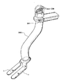
図128を参照すると、肋骨牽引子296は、ブレード297が肋骨に係合して該肋骨を押し開く開位置において図示されている。従来式ラチェット手段299を端部に取り付けられて有する1対の安定化棒298は、牽引子の下に配置されている。このラチェット手段299は、安定化棒298上の複数個の歯300と、安定化棒298を解除機構により解除しない限り1方向に移動させる歯止め孔部301とを具える。安定化棒298は、下方に湾曲しており、該棒がラチェット手段299を通って前進されると、安定化棒298の最下部分が吻合部位に隣接する位置で拍動する心臓301aに係合するようになっている。
【0111】
図129を参照すると、心臓に係合する安定化手段の部分の肋骨牽引子296に対する配向は、図128に示された実施例のものと同様である。この実施例では、接触部材1は、対向端部で少なくとも2つの可鍛支持部302に取り付けられ、該可鍛支持部は、さらに肋骨牽引子296に取り付けられる。これらの可鍛支持部302は、網状に織られるかまたは反復的なジグザグ構成を有していて、胸腔内に実質的に延長されうるステンレス鋼の帯で作られることが好ましい。この構成により、吻合部位で安定化力を維持しうるだけの十分な引張り強度を有すると同時に、外科医が可鍛支持部302を胸腔内で操作して拍動する心臓に対する所望の配向を達成することができる可鍛支持部302が得られる。
【0112】
上述されたように、軸手段3の上端部において、軸手段3は、拍動する心臓と一緒には動かないいかなる面または構造体であってもよい固定支持体に取り付けられうる。たとえば、軸手段3は、肋骨を押し開いて心臓への接近路を得るのに用いられる牽引システム上の固定具に取り付けられてもよく、または患者に接続されない手術台またはそれに付随する孔部等の固定構造体に取り付けられてもよい。好適な実施例においては、軸手段3は、軸手段3を受けて処置中に軸手段3の位置および配向を維持するように設計された牽引システムの構成要素に直接取り付けられる。
【0113】
図130および図131を参照すると、調節可能な摺動機構が軸手段3に設けられて、軸手段を牽引子に対して連続的に位置決めすることができるようになっている。たとえば、図130では、湾曲軸303は、調節可能なアーム305の端部に配設される玉継手304に挿通されており、この調節可能なアームは、軸手段を牽引子306に接続するとともに、牽引子306に対して固定されうる。湾曲軸303は、すでに述べたように玉継手304に挿通されており、軸303を玉継手304に対して摺動させることにより位置決めされて、接触部材1を可撓軸303によって限定される一定の円弧上のいかなる地点にも配置することが可能になっている。さらにまた、調節可能な軸305を用いて、湾曲軸303全体を牽引子ブレード307の長手に対して垂直方向に離間させて位置決めすることもできる。図131に、調節可能アーム305のAーAにおける平面図が示されており、調節可能アームは、その本体内にスロットまたは溝を形成されて有していて、該アームが固定機構308により位置固定されるまで連続的に位置決め可能とされてもよい。つまみ312cは、玉継手304の位置を位置固定する。
【0114】
図132において、軸手段3は、牽引子313に固定される締付機構312内に配設された心棒311のまわりを摺動する1対の平行軸309および310を具える。牽引子313に対する軸手段3の位置は、軸手段3を心棒311に沿って摺動させることによって調節されうる。移動ハンドル311aは、接触部材1を相応に移動させる。締付つまみ312cは、把持部材312a、312bをポート312dおよび軸309、310上で同時に固定する。
【0115】
図134を参照すると、牽引子またはその他の安定支持体と本発明の心臓を安定させる手段との間の距離を連続的に調節する調節可能なアームが得られうる。この調節可能なアームの一方の端部で、軸手段3は、調節可能なアームの本体内に形成されるソケット315内に内包された玉継手314に挿通される。玉継手314の締付けは、ソケット315に設けられかつ調節可能なアームの本体318を貫通する軸316を締め付けることによって調節されうる。この締付け軸316は、さらに回転つまみ319に接続されており、この回転つまみにより、締付け軸316を介してソケット315を締め付けることによって玉継手314を締めたり緩めたりすることができる。軸手段3と玉継手314との間の距離もまた、調節可能なアームの本体内にスリットまたは溝321を形成することにより、安定支持部320に対して調節されうる。固定機構322は、この溝321内に配設されており、固定ハンドル323を作動させると、固定機構322が溝321のまわりで締め付けられることによって調節可能なアームの位置が固定されるようになる。
【0116】
図135、図136および図137には、調節可能な位置決めを可能にする異なる構成を有した複数部分からなる軸手段3が示されている。図135のものは、上側および下側の二重軸部材325a、325bおよび326a、326bを取り付ける蝶番を持つエルボ継手324を有しており、上側および下側の軸部材は、牽引子またはその他の安定支持体327に対して連続的に位置決めされるようになっている。この組立体は、牽引子に取り付けられ得、下側の二重ブレード軸部材326a、326bは、回転継手328により接触部材に取り付けられる一方で、上側の二重軸部材325a、325bは、第2の回転継手329により支持体に取り付けられる。図136のものは、牽引子ブレード330の下から延在することおよび第1および第2の軸332および333の間に設けられる少なくとも1つの円形継手のまわりで回転することによって水平面上に広がる位置に配置される2本の軸を有する。第2の軸333の端部において、玉継手335を近位端に設けられて有する第3の垂直軸334を接触部材1に配設することができ、この第3の軸は、第2の軸部材333に固定される。
【0117】
本発明の軸手段の特に有用な特徴の1つは、軸手段の遠位端を連続的な態様または入れ子状の態様で延ばして、牽引子またはその他の安定支持体に取り付けられる軸手段の近位端に対して接触部材が下方に連続的に位置決めされうるようにすることができるという点である。下方への延長は、複数の機械的な実施形態で得られうる。図137には、上軸338内に同心的に配向される下軸337と、この下軸337の位置を上軸338に対して固定する固定手段339とを有する入れ子状軸部材336が示されている。さらに、接触部材1は、下軸337の遠位端にある旋回軸339により位置決めされうる。上軸338は、さらにまた上軸338の牽引子ブレード330に対する角度を調節する傾斜機構340によって、牽引子ブレード330に対して位置決めされうる。
【0118】
図138、図139および図140を参照すると、本発明の安定化手段は、1本または複数本の軸の近位端を牽引子に固定する複数個の調節可能な取付け部によって得られうる。たとえば、図138では、複数本の入れ子状軸手段341は、複数の旋回軸継手342または牽引子ブレード343上の蝶番に固定されて、接触部材1は、切開部の一方の縁部を把持する牽引子ブレード343に対して3次元的に連続的に位置決めされうるようになっている。引き込まれた時には、接触部材1は、牽引子ブレード343に形成される凹状ハウジング343a内に完全に収容される。
【0119】
図139の実施例では、第1の蝶番345により固定または固定解除されることで垂直方向に位置決めされるとともに、第2の蝶番346のまわりを揺動または回転しうる固定可能な回転式アーム344が用いられており、いずれの蝶番も牽引子アームまたは牽引子ブレード343に取り付けられる。
【0120】
図140では、軸手段は、牽引子アーム349または牽引子ブレード343に沿った地点で入れ子状軸手段348の近位端に固定される調節つまみ347を有する。この調節つまみ347を緩めることによって、入れ子状軸手段348は、牽引子アーム349および牽引子ブレード343に対して伸縮され得、以て接触部材1を正位置に揺動させて拍動する心臓に接触させることができる。
【0121】
図141の実施例において、最近位端にハンドル351を有する可撓性中央軸350は、一連の軸案内部352、353および354であることが好適な少なくとも1つの軸案内部352内に配設される。ハンドル351は、手で保持されるようになっており、可撓性中央軸350を回転させることおよびハンドル351の伸縮により接触部材1を位置決めすることをいずれも可能にする。一連の軸案内部352、353および354のいずれかを直線状にするかまたは所定の湾曲を持つ形状にして中央軸350の方向を変化させてもよい。近位側軸案内部354は、外科的切開部を開かせるのに用いられる牽引子355と一体化されうる。図141の特に好適な小型の実施例は、牽引子ブレード357のアームを互いに接続する横部材356に一体的に付随する軸案内部354を有する。中央軸350の遠位端にある軸手段3は、希望に応じて直線状または湾曲状かつ剛性または可撓性とされうる。中央軸350の位置を固定するために、固定機構358が、好ましくは中央軸350の近位部分に設けられて、中央軸の位置を軸案内部352、353および354に対して固定する。
【0122】
図142を参照すると、上述したように、肋骨牽引子に取り付けることは、安定化手段の位置および配向を固定する好適な技術である。したがって、本発明の安定化手段は、肋骨牽引子359に取り付けられる固定具に取り付けられうるか、または肋骨牽引子359の一部分の本体に直接組み込まれるように構成されうることが有利である。外科用肋骨牽引子359は、通常的に、ブレード361を取り付けられて有する本体360を具えており、これらのブレードは肋骨に係合して、牽引子359を動作させてブレード361を互いに離れる方向に移動させると、肋骨が押し開かれる。後退したブレード361によって創出される空間は、心臓への接近路となる。このため、一旦牽引子359が開位置に固定されると、安定化手段を心臓に適用して、軸手段3の位置および配向を肋骨牽引子359に対して固定することにより、吻合部位で安定化力を維持することができる。再び図142を参照すると、軸手段3は、牽引子359の本体360を全幅にわたって横断し得、軸手段3が挿通される円形開口365を有する上板362および下板363により正位置に保持されており、この円形開口は、上板362と下板363との間に配置される球体365の位置を維持する。開口364の大きさは、軸手段3の直径より大きいが、球体365の最大直径より小さい。このため、軸手段3は、球体365を貫通し、球体365の略中心に位置する地点のまわりで旋回しうる。
【0123】
図143を参照すると、本発明の安定化手段は、外科用牽引子の個別のアーム367を接続する横アーム366から延在する軸手段3によって得られ得、軸手段3が牽引子ブレード368に取り付けられるアーム367間でかつ牽引子ブレード368の位置より下に延在して、接触部材1と別個の軸369とが牽引子ブレード368の位置より下に配置されかつ通常的に胸腔内に内包されるようにすることができる。この実施例は、小型の設計であり、軸手段3の一部分は、胸腔内まで延在し、その遠位端370から延在する第2の実質的に水平な軸369を有する。
【0124】
図144を参照すると、本発明の安定化手段は、肋骨372のいずれの側にも固定されて、軸手段3に対する安定支持体を形成する肋骨固定機構371を備えうることが有利であり、軸手段3は、この肋骨固定機構371から胸腔内へと延在する。肋骨固定機構371は、好ましくは該肋骨固定機構371の本体内に形成されるスロット376内に配設されかつ2本の隣接する肋骨372、373の間に配置される調節可能な柱373と、切開部に最も隣接した肋骨372の反対側に固定されるブレード374とを具える。ブレード374の位置は、機構371をスロット376に沿って摺動させて、固定用ラッチ373を用いて位置固定することにより、柱373に対して調節されうる。
【0125】
本明細書で言及されているように、本発明の安定化手段の実施例は、心臓を位置決めして、迂回手術または拍動する心臓の位置が調節されうるその他の何らかの心臓手術を行ないやすくするのにも用いられうる。図145を参照すると、希望に応じて図144の実施例を改良して、同一または同等の肋骨固定機構371aに固定される軸手段3と、接触部材1とに、接触部材1を拍動する心臓の周縁部のまわりのある位置に維持しるような長さと引張り強度とを持たせるだけで、心臓位置決め装置として用いることができる。
【0126】
本明細書ですでに説明された接触部材および該接触部材に関連ある特徴に関する複数の設計との組合せで、接触部材に取り付けられる要素、主として軸手段の形状および構造は、部分的に接触部材を具えていてもよく、本発明の精神から逸脱することなしに複数の異なる設計で提供されうる。すでに示されたように、特定の形態は、特定の処置に関する外科的要求による場合があり、拍動する心臓に接近するのに用いられる外科的切開部の性質による。たとえば、本発明の一部の実施例は、侵入を最小限に抑えた切開部が創出される場合に特に有用であり、処置は、心臓への接近路となるカニューレまたは中空軸を通して装置を導入することによって行われる。図146〜図149に、拍動する心臓を安定させる手段が、吻合部位のまわりに手術野を限定する中空軸386に一体化されるかまたは厳密に付随して設けられる本発明の実施例が示されている。図146では、標的血管389を吻合するための手術野を限定する2つの半円筒状部分388および388bに分割される下側円筒状部分387を有する中空軸386が用いられている。
【0127】
底面390は、血管389を通す開口391を有していて、血管が開口391内かつ中空軸386の分割により創出されて手術野を創出する大空間内に配置されるようになっていることが好ましい。この実施例では、この装置の中空軸部分386または外軸の下側部分387の分割部分のいずれを介して装置を導入して、安定化と血管389への接近とを達成することもできる。軸の下側部分387の開放動作は、回転されたときに下側部分387を半円筒状部分388aおよび388bに分割する回転式軸手段3によって達成されうる。
【0128】
図147を参照すると、拍動する心臓に底面390のまわりで接触して安定化機能を果たすとともに、複数個の開口393を本体394に設けられて有する単体の中空軸392を用いることができる。底面390に少なくとも1つの通路395を設けて、標的血管389をこの通路395内に配置しうるようにすることが好ましい。第2の通路396を、単体の中空軸392の底面390の好ましくは対向端部に設けて、血管が開口395、396を通り抜けられるようにしてもよく、または単一の開口が設けられる場合(図示せず)は、開口395に対向する底面縁部が閉塞装置の働きをする。単体軸392の本体により大きい開口397を設けて、外科医が標的血管389に単体軸392の本体を通じて接近しうるようにしてもよい。
【0129】
図148に、すでに説明されたものと同じタイプではあるが、1対の接触部材1を形成されて有する中空軸要素398が示されているが、これらの接触部材は、軸要素399の下側部分401に設けられる蝶番または旋回軸400により、軸の本体399から広げ出される。外科的切開部を通して軸要素398が挿入される時には該軸要素と実質的に一体化して維持される接触部材1を広げ出すことにより、接触部材1は、拍動する心臓の表面に係合し、安定化機能を果たす。外科医は、軸要素398の中空部分またはそれ以外の方向から装置を導入して、吻合を行なうことができる。
【0130】
図149を参照すると、安定化力は、軸要素398により創出される手術野の真下に加えられる必要がある。図149の実施例は、軸要素398の底部391に形成される環状リング402を有しており、このリングは、軸要素398の壁を貫通しかつ環状リング402に固定されるロッド403または軸手段3により与えられる軸のまわりで回転されうる。ロッド403を回転させることにより、環状リング402は回転して軸要素398の底部391から脱出し、軸要素398に隣接しかつ正接する位置で接触する輪のような態様で、拍動する心臓に接する位置に配置されうる。本明細書で説明されるその他の実施例のように、安定化力を加える環状リング構造402は、少なくとも1つの通路464を底面に形成されて有していて、血管389が該通路内に配置されうるようになっていてもよい。通路464は、リング402全体を通り抜けて、該リングを、移植片が心臓に締結される吻合部が形成された後に手術野から容易に除去されうる「C」または「V」形の接触部材(図示せず)とするものであってもよい。これに代わる方法として、リング構造402は、必要な場合には切断または分解されて除去されてもよい。
【0131】
図150を参照すると、この実施例の安定化手段は、心臓のまわりに帯状に巻き付いて心臓の動きを抑制する細長鞘部材405を具える。この実施例は、外科的接近路を得る開胸術と併せて用いられうるが、拍動する心臓への接近路が胸骨切開術によって得られる場合に特に有用である。この鞘部材405は、心臓を取り巻く位置に配置され、鞘部材405の各々の端部が胸骨切開部を通って胸腔の外に延在するように操作される。所望の場合には、各々の鞘部材405の少なくとも一方の端部を牽引子406に取り付けて、鞘部材405の位置を固定する。鞘部材405は、心臓の外面に係合して心臓を正位置に保持する複数個の支持用付属物407を有しうる。支持用付属物407が心臓の表面に接触する地点において、支持用付属物407は、心臓と直接接触する表面に取り付けられる摩擦手段4(図示せず)を有していてもよい。支持用付属物407は、心臓と鞘部材405との間の緩衝体となって、心臓の動きを吸収しながら心臓を安定させる流体充填部材408を有するかまたは具えていてもよい。鞘部材405が1つ以上の流体充填部材408を有する場合は、鞘部材405は、さらにまた空気または生体適合性流体を膨張可能な部材408に導入する少なくとも1つの管腔409を有していてもよく、これらの膨張可能な部材は別々にまたは同時に膨張されうる。前者の場合には、各々の膨張可能な部材408に関して別々の管腔409が設けられる。鞘部材409の胸腔内への挿入は、膨張可能な部材408が収縮されている時に行なわれ得、手動でまたは従来式案内装置および/または案内ワイヤにより達成される。各々の支持用付属物407は、鞘部材405に永久的に取り付けられてもよく、または鞘部材405の長手に沿って摺動してもよい。これに代わる方法として、膨張可能な部材408を単独でまたは他の膨張可能な部材と組み合わせて、標的冠状動脈に直接隣接する位置に配置することで、より局所的な安定化を達成することができる。このように、本発明の膨張可能な部材は、心臓の冠状動脈の横または周囲に配置され得、外科的処置を行なうための開口または孔部を本体に設けられて有しうる。膨張可能な部材408が、心臓と囲心嚢または肋骨の裏側等の外囲構造との間の空間を満たすと、さらなる安定化力が加えられうる。膨張可能な部材408を適切に膨張させると、標的動脈の部位は、接触部材1や外科的切開部の縁部裏側等の隣接する安定化構造に押し付けられうる。さらにまた、流体充填式または膨張式の緩衝手段または安定化手段または位置決め手段は、剛性、可鍛性、変形可能または取外し可能の軸、ハンドル、取り付け部または膨張手段により適用されうる。
【0132】
同様に、図151を参照すると、対向する牽引子ブレード411の上を通って心臓の下を通過するように配置されかつ両端部で帯411を選択的に移動させるクランク412に取り付けられうる帯410を用いることができる。クランク412を回転させるか、またはその他の方法で帯411の位置を操作することによって、心臓を回転させて選択的に位置決めすることまたは心臓のさまざまな部分に接近可能にすることができる。クランク412は、侵入を最小限に抑えた開胸術において肋骨を押し開いておくのに用いられる牽引子に取り付けられると有利である。
【0133】
上述されたように、拍動する心臓の安定化に加えて、本発明の装置および方法は、図150および図151に示されるように心臓を選択的に位置決めするのにも用いられうる。また、図152〜図154に示されるように、連続的な帯411に代わるものが、図152、図153および図154に示されており、心臓の下に配置される実質的に偏平な可撓シート413を具える。このシート413の一方の面にヒドロゲル414のコーティングまたは心外膜表面に付着する同様の材料のコーティングを施してもよい。シート413のもう一方の面は平滑であることが好ましい。好適な実施例では、2枚のシート413がそれぞれの縁部で連結されて、両者間に介在空間(図示せず)が形成される。この介在空間が流体で灌流されることにより、ヒドロゲル414が軟化して、シート413を容易に再配置または除去することができる。
【0134】
外科的処置の性質によっては、接触部材1の位置を手術野から遠く離れた地点から操作することにより、該接触部材を正位置に固定することが望ましい場合がある。図155の実施例では、接触部材1と自身の最遠位端で係合する複数本の入れ子軸415が用いられている。各々の入れ子軸415は、牽引子ブレード416上の地点に固定されて、以て入れ子軸258を集合的に調節して、接触部材1を手術野内で入れ子軸415の移動範囲内のいかなる地点にも位置決めしうることが好ましい。各々の入れ子軸258の最近位端で、該軸は、各々の入れ子軸415の配向を牽引子ブレード416に対して固定する液圧アクチュエータ417により、牽引子ブレード416に固定される。各々の液圧アクチュエータ417は、非膨張形液圧ホース419を介してロック弁418に取り付けられる。一般的に、このロック弁は、液溜め420と、ロック弁418を閉鎖して液圧アクチュエータ417を位置固定する手動スイッチ421とを具える。いかなる本数の入れ子軸415を用いてもよいが、複数の取付け点を牽引子ブレード418上のさまざまな位置に設けて、外科医が、少なくとも3本であることが好適な複数の入れ子軸415を、各々の外科的処置に最も適した位置で牽引子ブレード416に個別に取り付けうるようにすることが好ましい。
【0135】
図156〜図157の実施例を参照すると、接触部材が拍動する心臓の動きによって上方に変位する時に継手と調節可能なアームとを一定の構成に固定する選択的に配置された摩擦面を付随して有する継手により接続される複数本のアームを具えた安定化手段が用いられている。図157を参照すると、牽引子ブレード416は、第1の湾曲重ね板ばね422cを伸張させて第1の軸424の位置を牽引子ブレードに対して固定するハンドル422bにより作動する内側カム軸422aを備えた固定機構422を有する。図156に示されるように、第1の軸424は、第1の摩擦継手425に取り付けられており、前記継手は第1の軸424に対して垂直な軸のまわりで回転しうる。図158を参照すると、摩擦継手425は、第1の軸424に固定される下側ハウジング426と、第2の軸428に固定される上側ハウジング427とを具え、この第2の軸は、第1の軸のように別個の円筒軸であってもよく、または摩擦継手425のハウジングの延長部分であってもよい。上側ハウジング427と下側ハウジング426との間に、玉ピボット429が配置されて、個別のハウジングを互いに回転させる。上側ハウジング427または下側ハウジング426のいずれか一方は、摩擦面430を内部に設けられて有しており、反対側のハウジングは431等の摩擦係合手段を有する。いずれかのハウジングが玉ピボット429のまわりで傾斜することにより変位しても、摩擦面430が摩擦係合手段431に接触して、摩擦継手425の位置が固定される。第2の軸は、第1の摩擦継手と同等の構造を有する第2の摩擦継手に接続されてもよい。
【0136】
図156および図159を参照すると、回転可能な軸手段433は、歯止め機構を有するハウジング438内に配設される中央ロッド434を具えており、この歯止め機構は、前記中央ロッド434のまわりの歯に係合して回転可能な軸手段433の回転位置を固定する舌435で形成される。回転可能な軸手段433は、たとえば歯(図示せず)が成形舌437と係合することによって回転に抵抗する軸439を有した蝶番436により、接触部材1に接続される。
【0137】
図160〜図163の実施例では、牽引子ブレード440は、クリップを受けるようになっており、このクリップに、自身の遠位端にある伸縮可能な軸手段と該伸縮可能な軸を伸長させる手段とを有する可撓スライドが挿入される。図162を参照すると、この組立体は、安定化手段を牽引子ブレードに取り付けるC形クリップ441を含む。このクリップは、牽引子ブレード440に形成される案内部443内に嵌入するようになっている少なくとも1つの溝442を有する。クリップ441の本体は、さらにまた、図160および図161と図162の点線とに示されるように、湾曲部分の外側まわりに可撓スライド445が挿入されるスロット444を有する。図163に、クリップ441に形成されたスロット444の内側に嵌入する可撓スライド445が示されており、この可撓スライドは、スロット444を通ってクリップ441に侵入し、クリップ441の形状に沿って該クリップのまわりで湾曲するようになっている。ブロック446は、可撓スライド445の遠位端に取り付けられる。
【0138】
伸縮可能な軸手段447は、このブロック446に取り付けられており、注射器449またはその他の同様の流体内包装置と流体接続されて、管448を介して液圧を加えて軸手段447を伸長させる膨張不能な液圧管448を有する。注射器には、逃がし弁451を備えた1方向弁450を設けて、液圧を加えて伸縮可能な軸手段447を漸進的に前進させる一方で、1方向弁450により伸縮可能な軸手段447の収縮が防がれるようにすることが好ましい。処置が完了すると、液圧は、逃がし弁45を作動させることによって解除される。
【0139】
図160を参照すると、外科医は、最初にクリップ441を牽引子ブレード440に挿入してから可撓スライド445をスロット444に挿入する。そして、可撓スライド445をクリップ441の最上部から最下部まで前進させて、最終的に伸縮可能な軸手段447を正位置につけ、この軸手段を伸長させることで接触部材1を心臓と整合的に係合させることができるようにする。片手で注射器449を用いて流体を伸縮可能な軸447に注入して、接触部材1を心臓に係合させる。牽引子ブレード440内の案内部443をブレード440の全長に延在させて、クリップ441をブレード440に沿って選択的に位置決めすることができるようにしうることにも注意されたい。
【0140】
図164を参照すると、本発明の拍動する心臓を安定させる手段が、肋骨牽引子452および心拍動式CABG処置に用いられうるさらに他の装置453、454と一緒に用いられている様子が示されている。使用時には、牽引子のブレード455は、肋骨を引き離して、以て本発明の安定化手段を含む外科用装置を導入する接近路となる空間を作り出す。こうして、安定化手段を心臓に接触させて、接触部材1を標的動脈456に隣接させるようにする。安定化手段を好ましくは肋骨牽引子452に取り付けることにより正位置に固定することを含めて、拍動する心臓の動きを最小限に抑えうる程度の大きさの安定化力を加える。
【0141】
図165を参照すると、安定化手段は、1対の実質的に平面状の矩形接触部材1を具えており、これらの接触部材は、標的動脈456に隣接して配置される。軸手段3は、肋骨牽引子452に手軽に取り付けられうるように変形可能となっている。図165に示されているように、外科医は、接続軸2および接触部材1の配向と位置とを軸手段3に対して容易に調節しながら、装置の近位端にあるつまみ457を操作することにより、安定化手段を心臓と連続的に接触させることができる。図166に、処置のその後の段階として、標的動脈456を縫合することにより吻合が完成されている様子が示されている。このように、安定化手段は、処置の継続時間にわたって吻合部位で安定化力を維持する。
【0142】
上記で本発明の複数の実施例に関して述べたように、安定化手段は、心臓手術の前段階で肋骨を押し開くのに用いられる牽引子等の関連ある外科用装置と一体化されうることが有利である。図167には、侵入を最小限に抑えた手術において、肋骨を押し開くのに適した牽引子459のアームと一体化される1対の軸手段3を有する本発明の実施例が示されている。安定化手段は、接触部材1を位置決めするのに用いられる前述のような調節可能な連結部459を有する軸を具える。さらにまた、軸手段3は、牽引子ブレードのアーム458に直接固定される玉継手460に挿通されており、軸手段3および接触部材1の位置を正位置に固定する調節可能なハンドル460で終端する。
【0143】
すでに述べたように、本発明の目的は、拍動する心臓に対する侵入を最小限に抑えたCABG処置を行ないやすくする装置または1揃いの装置を提供することにある。したがって、本明細書に開示された各々の装置は、複数の個別の装置が一纏めに包装されて、外科医が拍動する心臓に対して縫合を行なうのに必要な各々の装置を利用することができる総合キットとして提供されることが好ましい。本明細書で説明された拍動する心臓を安定させる手段は、胸腔内に直接導入され、拍動する心臓と直接物理的に接触するため、本明細書で開示された各々の装置は、その他の外科用装置に適した滅菌処理を受ける必要がある。本明細書で説明された装置の実質的な部分は、生体適合性を有する滅菌処理可能なプラスチックで形成されかつ装置を完全に密閉する滅菌容器内に維持されており、この容器が微生物に対する防護体となり、本発明の安定化手段およびこれらの装置が一括包装される容器が滅菌されることが特に好ましい。容器および容器内に入れられる装置の滅菌は、ETOガス、高温高圧またはガンマ線照射等の従来式滅菌方法により達成されうる。容器は、本発明の装置が入れられて密封される前または後のいずれの時点でも滅菌可能な密封式可撓袋であることが好ましい。
【0144】
本明細書に記載された特定の例は、説明を目的としており、当業者が本発明を適用しうる用途を制限するものと解釈されるべきではない。当業者は、特許請求の範囲に示される精神および範囲内に含まれる改変およびその他の使用方法を行なうことができる。
【図面の簡単な説明】
【図1】 バイパスが縫合される部位に隣接する位置で心臓と係合するように配向される1対の実質的に平面状の接触部材を有する、拍動する心臓を安定させる手段の図であり、複数の方向に調節可能でありかつ牽引子またはその他の固定支持構造体に取り付けられうる軸手段に取り付けられた接触部材も示されている。
【図2】 軸手段の詳細と、調節可能な位置決め機構の構造とを示す図である。
【図3】 接触部材の底面に固定されることが好適な摩擦手段を有する接触部材のさまざまな構成を示す図である。
【図4】 接触部材の底面に固定されることが好適な摩擦手段を有する接触部材のさまざまな構成を示す図である。
【図5】 接触部材の底面に固定されることが好適な摩擦手段を有する接触部材のさまざまな構成を示す図である。
【図6】 接触部材の底面に固定されることが好適な摩擦手段を有する接触部材のさまざまな構成を示す図である。
【図7】 接触部材の底面に固定されることが好適な摩擦手段を有する接触部材のさまざまな構成を示す図である。
【図8】 接触部材の底面に固定されることが好適な摩擦手段を有する接触部材のさまざまな構成を示す図である。
【図9】 接触部材の底面に固定されて、製造しやすくかつ使い捨て可能であるという利点を提供する差込み式部材の一例を示す図である。
【図10】 接触部材の底面と拍動する心臓の表面との間に配置される膨張式または流体充填式の緩衝部材を有する本発明の安定化手段の一例を示す図である。
【図11】 拍動する心臓に係合し、かつ調節可能な重りと釣合重りとで構成される平衡質量を介して安定化力を付与することにより心臓の安定化を達成するシステムの一部分をなしうる重り付き接触部材を有する本発明の実施例の図であり、図11は、重り付き接触部材の断面図である。
【図12】 血管を位置決めする開口を両者間に設けられて有する接触部材の図である。
【図13】 重心に固定される、調節可能な重りと釣合重りとを有する軸に結合される接触部材の図である。
【図14】 1対の接触部材の反対側に配置される逆向き接触部材と、両者間の中間地点に配置される軸とを有する本発明の実施例の図である。
【図15】 整合可能な形状を持つ接触部材を有しており、可撓性または半剛性部材が該接触部材の本体に通されうる本発明の実施例の図である。
【図16】 整合可能な形状を持つ接触部材を有しており、可撓性または半剛性部材が該接触部材の本体に通されうる本発明の実施例の図である。
【図17】 軸手段の遠位端を着脱可能に取り付けるポートを有する接触部材の実施例の図である。
【図18】 軸手段の遠位端を着脱可能に取り付ける複数個のポートが接触部材の周縁部のまわりに設けられた実施例の図である。
【図19】 接触部材のポートに嵌合するようになっている遠位端を有する別個の軸が用いられる本発明の実施例の図である。
【図20】 侵入を最小限に抑えた用途のために、接触部材が軸手段の遠位端によって形成される本発明の実施例の図である。
【図21】 軸手段の遠位部分を連結する相互接続部材の図である。
【図22】 軸に固定される実質的に環状の接触部材を有しており、該軸は、この環状の接触部材のまわりを回転し得、かつ接触部材の周縁部のまわりの任意の地点で正位置に固定されうる本発明の実施例の図である。
【図23】 正圧または負圧が接触部材に隣接する位置に付与される本発明の実施例の図である。
【図24】 正圧または負圧が接触部材に隣接する位置に付与される本発明の実施例の図である。
【図25】 正圧または負圧が接触部材に隣接する位置に付与される本発明の実施例の図である。
【図26】 正圧または負圧が接触部材に隣接する位置に付与される本発明の実施例の図である。
【図27】 正圧または負圧が接触部材に隣接する位置に付与される本発明の実施例の図である。
【図28】 正圧または負圧が接触部材に隣接する位置に付与される本発明の実施例の図である。
【図29】 正圧または負圧が接触部材に隣接する位置に付与される本発明の実施例の図である。
【図30】 拍動する心臓と接触部材とが接触する部位を照明する光源が設けられた本発明の実施例の図である。
【図31】 外科用覆いを接触部材に操作可能に付随させて、隔絶された視野を提供する本発明の実施例の図である。
【図32】 外科用覆いを接触部材に操作可能に付随させて、隔絶された視野を提供する本発明の実施例の図である。
【図33】 外科用覆いを接触部材に操作可能に付随させて、隔絶された視野を提供する本発明の実施例の図である。
【図34】 吻合の完成を容易にする装置を付随して有する本発明の接触部材の図である。
【図35】 軸手段が別個の血管保持装置を付随して有する本発明の実施例の図である。
【図36】 侵入を最小限に抑えて本発明の安定化手段の挿入を達成させる好適なカニューレ組立体の図であり、図36は、カニューレ組立体を胸壁に取り付けるねじを有するカニューレ組立体の図である。
【図37】 カニューレの周縁部のまわりにねじ部を有するカニューレ組立体の図である。
【図38】 隣接する肋骨に係合するように設計された固定機構の図である。
【図39】 隣接する肋骨に係合するように設計された固定機構の図である。
【図40】 隣接する肋骨に係合するように設計された固定機構の図である。
【図41】 拍動する心臓の表面に係合する小径遠位端と、外科用装置を拍動する心臓まで導入する大径近位端とを有する円錐形カニューレの図である。
【図42】 カニューレにより侵入が最小限に抑えられる態様で胸壁を通して挿入されて、接触部材を拍動する心臓に係合させる本発明の実施例の図である。
【図43】 カニューレにより侵入が最小限に抑えられる態様で胸壁を通して挿入されて、接触部材を拍動する心臓に係合させる本発明の実施例の図である。
【図44】 侵入を最小限に抑えて可撓性接触部材が挿入および抜出されるように設計されており、接触部材は、引込状態で軸の中空部分内に維持され、中央軸の延長と同時に展開する本発明の実施例の図である。
【図45】 侵入を最小限に抑えて可撓性接触部材が挿入および抜出されるように設計されており、接触部材は、引込状態で軸の中空部分内に維持され、中央軸の延長と同時に展開する本発明の実施例の図である。
【図46】 侵入を最小限に抑えて可撓性接触部材が挿入および抜出されるように設計されており、接触部材は、引込状態で軸の中空部分内に維持され、中央軸の延長と同時に展開する本発明の実施例の図である。
【図47】 侵入を最小限に抑えて可撓性接触部材が挿入および抜出されるように設計されており、接触部材は、引込状態で軸の中空部分内に維持され、中央軸の延長と同時に展開する本発明の実施例の図である。
【図48】 侵入を最小限に抑えて可撓性接触部材が挿入および抜出されるように設計されており、接触部材は、引込状態で軸の中空部分内に維持され、中央軸の延長と同時に展開する本発明の実施例の図である。
【図49】 侵入を最小限に抑えて本発明の接触部材の挿入および抜出を達成することができ、個別の接触部材は、軸の遠位端にある蝶番により正位置まで回転されるさらに他の実施例の図である。
【図50】 侵入を最小限に抑えて本発明の接触部材の挿入および抜出を達成することができ、個別の接触部材は、軸の遠位端にある蝶番により正位置まで回転されるさらに他の実施例の図である。
【図51】 侵入を最小限に抑えて本発明の接触部材の挿入および抜出を達成することができ、個別の接触部材は、軸の遠位端にある蝶番により正位置まで回転されるさらに他の実施例の図である。
【図52】 侵入を最小限に抑えて本発明の接触部材の挿入および抜出を達成することができ、個別の接触部材は、軸の遠位端にある蝶番により正位置まで回転されるさらに他の実施例の図である。
【図53】 軸のまわりに配置される案内部に取り付けられて、案内部が下方に移動することによって接触部材の展開が引き起こされるようになっている接触部材の図である。
【図54】 軸のまわりに配置される案内部に取り付けられて、案内部が下方に移動することによって接触部材の展開が引き起こされるようになっている接触部材の図である。
【図55】 軸のまわりに配置される案内部に取り付けられて、案内部が下方に移動することによって接触部材の展開が引き起こされるようになっている接触部材の図である。
【図56】 軸のまわりに配置される案内部に取り付けられて、案内部が下方に移動することによって接触部材の展開が引き起こされるようになっている接触部材の図である。
【図57】 接触部材を正位置まで延在させる複数本の支柱により軸手段に取り付けられる本発明の接触部材の図である。
【図58】 接触部材を正位置まで延在させる複数本の支柱により軸手段に取り付けられる本発明の接触部材の図である。
【図59】 複数個の蝶番により軸手段の遠位端のまわりで回転可能な本発明の接触部材の図である。
【図60】 複数個の蝶番により軸手段の遠位端のまわりで回転可能な本発明の接触部材の図である。
【図61】 複数個の蝶番により軸手段の遠位端のまわりで回転可能な本発明の接触部材の図である。
【図62】 複数個の蝶番により軸手段の遠位端のまわりで回転可能な本発明の接触部材の図である。
【図63】 複数個の蝶番により軸手段の遠位端のまわりで回転可能な本発明の接触部材の図である。
【図64】 器具の本体から延ばされると接触部材が展開するように輪をなしており、ワイヤの一部分を器具の本体内に引き込むことによって侵入が最小限に抑えられる態様で抜出されうる単一ワイヤで形成される接触部材を有する実施例の図である。
【図65】 器具の本体から延ばされると接触部材が展開するように輪をなしており、ワイヤの一部分を器具の本体内に引き込むことによって侵入が最小限に抑えられる態様で抜出されうる単一ワイヤで形成される接触部材を有する実施例の図である。
【図66】 器具の本体から延ばされると接触部材が展開するように輪をなしており、ワイヤの一部分を器具の本体内に引き込むことによって侵入が最小限に抑えられる態様で抜出されうる単一ワイヤで形成される接触部材を有する実施例の図である。
【図67】 接触部材が、軸の中空部分内に引き込まれて侵入を最小限に抑えながら挿入および抜出されうる渦巻き状巻線で形成される本発明の実施例の図である。
【図68】 接触部材が、軸の中空部分内に引き込まれて侵入を最小限に抑えながら挿入および抜出されうる渦巻き状巻線で形成される本発明の実施例の図である。
【図69】 接触部材が、軸の中空部分内に引き込まれて侵入を最小限に抑えながら挿入および抜出されうる渦巻き状巻線で形成される本発明の実施例の図である。
【図70】 挿入時または抜出時に軸の本体内に引き込まれることによって収縮されうる膨張可能な接触部材の図である。
【図71】 挿入時または抜出時に軸の本体内に引き込まれることによって収縮されうる膨張可能な接触部材の図である。
【図72】 膨張可能な環状帯で形成される本発明の接触部材の図である。
【図73】 膨張可能な環状帯で形成される本発明の接触部材の図である。
【図74】 軸の遠位端の分割部分で形成される接触部材の図である。
【図75】 軸の遠位端の分割部分で形成される接触部材の図である。
【図76】 標的動脈を操作する縫合糸を付随して有する接触部材の図である。
【図77】 標的動脈を操作する縫合糸を付随して有する接触部材の図である。
【図78】 標的動脈を操作する縫合糸を付随して有する接触部材の図である。
【図79】 標的冠状動脈内に嵌合するようになっている血管内安定化装置の図である。
【図80】 標的冠状動脈内に嵌合するようになっている血管内安定化装置の図である。
【図81】 前記心外膜組織を位置決めする手段を付随して有する本発明の接触部材の図である。
【図82】 前記心外膜組織を位置決めする手段を付随して有する本発明の接触部材の図である。
【図83】 標的動脈に隣接する心外膜組織を掻き集めるかまたは押し退ける回転式筒形ローラを有する本発明の接触部材の図である。
【図84】 標的動脈に隣接する心外膜組織を掻き集めるかまたは押し退ける回転式筒形ローラを有する本発明の接触部材の図である。
【図85】 手術部位の組織に係合して該組織を押し退ける延長部を有するばね付きフレームをさらに具えた1対の接触部材を有する、拍動する心臓を安定させる手段の図である。
【図86】 単一の軸手段を各々の接触部材に付随して有しており、これらの軸手段は相互接続されるとともに、旋回軸のまわりで独立して移動して、接触部材により標的冠状動脈に隣接する位置で心臓の表面組織が押し退けられて標的動脈の吻合部位における露出度が高まるようにする安定化手段の実施例の図である。
【図87】 単一の軸手段を各々の接触部材に付随して有しており、これらの軸手段は相互接続されるとともに、旋回軸のまわりで独立して移動して、接触部材により標的冠状動脈に隣接する位置で心臓の表面組織が押し退けられて標的動脈の吻合部位における露出度が高まるようにする安定化手段の実施例の図である。
【図88】 接触部材は、心外膜組織を押し退けるさらに別の構造体を付随して有し、これらの押し退け構造体は、接触部材の底面から延在するピンを具えうる本発明の実施例の図である。
【図89】 接触部材は、心外膜組織を押し退けるさらに別の構造体を付随して有し、これらの押し退け構造体は、接触部材の底面から延在するピンを具えうる本発明の実施例の図である。
【図90】 接触部材は、心外膜組織を押し退けるさらに別の構造体を付随して有し、これらの押し退け構造体は、接触部材の底面から延在するピンを具えうる本発明の実施例の図である。
【図91】 肋骨を開かせて心臓への手術路を確保する牽引子を内蔵するシステムを具えており、てこ装置と一緒に用いられて標的冠状動脈の露出度を高めうる1対の安定化板を具えた、拍動する心臓を安定させる手段の図である。
【図92】 肋骨を開かせて心臓への手術路を確保する牽引子を内蔵するシステムを具えており、てこ装置と一緒に用いられて標的冠状動脈の露出度を高めうる1対の安定化板を具えた、拍動する心臓を安定させる手段の図である。
【図93】 標的冠状動脈の両側の心外膜組織を圧下する固定可能な機構を有する本発明の実施例の図である。
【図94】 標的冠状動脈の両側の心外膜組織を圧下する固定可能な機構を有する本発明の実施例の図である。
【図95】 標的冠状動脈の両側の心外膜組織を圧下する固定可能な機構を有する本発明の実施例の図である。
【図96】 標的冠状動脈の両側の心外膜組織を圧下する固定可能な機構を有する本発明の実施例の図である。
【図97】 冠状動脈に隣接しかつ該冠状動脈を取り巻く部位で心臓に接触する実質的に平面状の安定化台の図であり、この安定化台は、動脈を通る血流を制限するかまたは皆無とする少なくとも1つの閉塞装置と、吻合部に隣接する組織を押し退ける関連装置とを付随して有しうる。
【図98】 軸部分を具えかつ標的動脈に係合する鈍い部分を有する動脈閉塞装置の図である。
【図99】 標的冠状動脈を閉塞させる構造体を付随して有する接触部材の図である。
【図100】 標的冠状動脈を閉塞させる構造体を付随して有する接触部材の図である。
【図101】 標的冠状動脈を閉塞させる構造体を付随して有する接触部材の図である。
【図102】 標的血管を取り巻きかつ可動軸または縫合糸案内部と接続されて用いられて標的血管を閉塞させうる縫合糸と一緒に用いられるフランジを付随して有する本発明の接触部材の図である。
【図103】 標的血管を取り巻きかつ可動軸または縫合糸案内部と接続されて用いられて標的血管を閉塞させうる縫合糸と一緒に用いられるフランジを付随して有する本発明の接触部材の図である。
【図104】 接触部材の平坦面に取り付けられることが好適な1つ以上の固定具を設けて、吻合処置における外科医の便宜のために鋏やピンセット、外科用縫合針等の外科用ツールまたは付属品を受けるようにしてある本発明の接触部材の実施例の図である。
【図105】 接触部材間に屈曲連結部または相互接続軸または軸手段を有しており、接触部材の連続的な位置決めを達成する本発明の実施例の図である。
【図106】 軸手段に付随する固定可能な連結部を有する本発明の実施例の図である。
【図107】 あらゆる方向に配置可能であるために、所要の安定度が達成されるように接触部材を配置配向して、その時点で安定化手段を有するアームを位置固定することができる可撓性の固定可能なアームの図であり、この可撓性の固定可能なアームは、牽引子に取り付けられ得、安定可手段全体が適正に配置されると剛化される。
【図108】 中空の筒形体および球体と、その内部に配置されてアームを正位置に固定する膨張可能な風船部材とを有する固定可能な整合性アームの図である。
【図109】 湾曲した噛み合い片を有しており、各々の噛み合い片の相互接続面に形成される歯がそれぞれの噛み合い片の回転を防止する本発明の実施例の図である。
【図110】 湾曲した噛み合い片を有しており、各々の噛み合い片の相互接続面に形成される歯がそれぞれの噛み合い片の回転を防止する本発明の実施例の図である。
【図111】 軸の位置を固定する手段を内蔵して有する可撓軸の図である。
【図112】 軸の位置を固定する手段を内蔵して有する可撓軸の図である。
【図113】 一連の調節可能な連結体が、ゴム弾性液圧液を内包して有しており、力を加えることによって、このゴム弾性液圧液が剛化して調節可能な連結体の位置を固定する本発明の実施例の図である。
【図114】 一連の調節可能な連結体が、ゴム弾性液圧液を内包して有しており、力を加えることによって、このゴム弾性液圧液が剛化して調節可能な連結体の位置を固定する本発明の実施例の図である。
【図115】 一連の調節可能な連結体が、ゴム弾性液圧液を内包して有しており、力を加えることによって、このゴム弾性液圧液が剛化して調節可能な連結体の位置を固定する本発明の実施例の図である。
【図116】 複数本のストランドを内部に配置されて有する可撓軸を有しており、これらのストランドが遠位部分で正位置に固定されることにより軸が剛性となる本発明の実施例の図である。
【図117】 複数個の管腔を内部に設けられて有しており、これらの管腔を密封することにより可撓軸の位置が固定されるようになっている可撓軸の図である。
【図118】 複数本のねじ付きケーブルが軸手段の近位部分に取り付けられており、これらのねじ付きケーブルを回転させることによって軸手段の近位部分が調節される微調節機構の図である。
【図119】 安定支持体に対する軸の垂直方向の動きを抑制するばね式または空気制動式機構を有する軸手段の実施例の図である。
【図120】 安定支持体に対する軸の垂直方向の動きを抑制するばね式または空気制動式機構を有する軸手段の実施例の図である。
【図121】 軸を垂直方向に位置決めする微調節機構を備えた本発明の軸手段の図である。
【図122】 軸を垂直方向に位置決めする微調節機構を備えた本発明の軸手段の図である。
【図123】 牽引子のブレードに取り付けられた固定具に配設されており、軸を垂直方向に位置決めするハンドルを有する柔軟軸の図である。
【図124】 ケーブルに取り付けられた複数個の噛み合い片で形成される調節可能なアームを具えた軸手段の図である。
【図125】 接触部材の位置が、軸手段の近位部分に配置されかつ複数本の位置決めワイヤにより遠位部分で玉継手に接続される位置決めハンドルによって調節される本発明の調節可能な軸手段の図である。
【図126】 接触部材の位置が、軸手段の近位部分に配置されかつ複数本の位置決めワイヤにより遠位部分で玉継手に接続される位置決めハンドルによって調節される本発明の調節可能な軸手段の図である。
【図127】 接触部材の位置が、軸手段の近位部分に配置されかつ複数本の位置決めワイヤにより遠位部分で玉継手に接続される位置決めハンドルによって調節される本発明の調節可能な軸手段の図である。
【図128】 肋骨牽引子の底面から懸下される安定化棒を有しており、これらの安定化棒は、歯止め手段に係合する本発明の安定化手段の実施例の図である。
【図129】 牽引子および接触部材に取り付けられる可鍛軸を有する実施例の図である。
【図130】 軸を安定支持体に対して調節可能に位置決めする機構を有する本発明の軸手段の図である。
【図131】 軸を安定支持体に対して調節可能に位置決めする機構を有する本発明の軸手段の図である。
【図132】 軸を安定支持体に対して調節可能に位置決めする機構を有する本発明の軸手段の図である。
【図133】 軸を安定支持体に対して調節可能に位置決めする機構を有する本発明の軸手段の図である。
【図134】 本発明の軸手段を安定支持体に取り付ける調節可能なアームの図であり、この軸手段は、該アーム上の固定具により調節される玉継手に通され、該アームは、ラッチ機構により安定支持体上で位置固定される。
【図135】 軸手段が牽引子のブレードに対して調節可能に位置決めされる本発明の軸手段の実施例の図である。
【図136】 軸手段が牽引子のブレードに対して調節可能に位置決めされる本発明の軸手段の実施例の図である。
【図137】 軸手段が牽引子のブレードに対して調節可能に位置決めされる本発明の軸手段の実施例の図である。
【図138】 牽引子ブレードまたは牽引子アームから延在しかつ該牽引子ブレードまたは牽引子アームに対して連続的に配置される本発明の調節可能な軸手段の図である。
【図139】 牽引子ブレードまたは牽引子アームから延在しかつ該牽引子ブレードまたは牽引子アームに対して連続的に配置される本発明の調節可能な軸手段の図である。
【図140】 牽引子ブレードまたは牽引子アームから延在しかつ該牽引子ブレードまたは牽引子アームに対して連続的に配置される本発明の調節可能な軸手段の図である。
【図141】 牽引子に固定される相互接続アームに取り付けられることが好適な複数個の軸案内部により位置決めされる、近位端にハンドルを有する中央軸を備えた実施例の図である。
【図142】 肋骨牽引子に動作可能に付随する1対の板と、これらの板の間に配設されて、軸手段を配向しやすくする球体とを有する本発明の安定化手段の実施例の図である。
【図143】 牽引子の相互接続棒から牽引子ブレードより下の位置まで延在しかつ実質的に水平な軸を有するアームを具えた軸手段を有する本発明の実施例の図である。
【図144】 肋骨固定機構に操作可能に付随する本発明の拍動する心臓を安定させる手段の図である。
【図145】 拍動する心臓を位置決めする手段として用いられるようになっており、肋骨固定機構に動作可能に付随する本発明の安定化手段の図である。
【図146】 軸手段が単一の中空軸を具えた本発明の実施例の図である。
【図147】 軸手段が単一の中空軸を具えた本発明の実施例の図である。
【図148】 軸手段が単一の中空軸を具えた本発明の実施例の図である。
【図149】 軸手段が単一の中空軸を具えた本発明の実施例の図である。
【図150】 心臓を取り巻く1箇所または複数箇所に配置される膨張可能な部材を含むかまたは具えうる複数の柔軟な支持用付属体を付随して有する外装部材を有しており、空気または生体適合性流体を導入する管腔が該外装部材内に設けられうる、拍動する心臓を安定させる手段の図である。
【図151】 いずれの端部も牽引子のアーム上に設けられるクランクに取り付けられる可動外装部材で形成される安定化手段の図である。
【図152】 片面にヒドロゲルの被膜を有することが好適な可撓性シート体を具えた、心臓を有利に位置決めする装置の図である。
【図153】 片面にヒドロゲルの被膜を有することが好適な可撓性シート体を具えた、心臓を有利に位置決めする装置の図である。
【図154】 片面にヒドロゲルの被膜を有することが好適な可撓性シート体を具えた、心臓を有利に位置決めする装置の図である。
【図155】 遠位端に接触部材を固定されて有する複数本の入れ子軸を具えており、この入れ子軸の位置が、液圧作動装置によって操作および固定される本発明の実施例の図である。
【図156】 拍動する心臓の動きにより接触部材が押圧された時に係合する複数個の摩擦継手を具えた整合性アームを有する本発明の実施例の図である。
【図157】 拍動する心臓の動きにより接触部材が押圧された時に係合する複数個の摩擦継手を具えた整合性アームを有する本発明の実施例の図である。
【図158】 拍動する心臓の動きにより接触部材が押圧された時に係合する複数個の摩擦継手を具えた整合性アームを有する本発明の実施例の図である。
【図159】 拍動する心臓の動きにより接触部材が押圧された時に係合する複数個の摩擦継手を具えた整合性アームを有する本発明の実施例の図である。
【図160】 伸縮可能な軸を可撓性スライドに取り付けられて有する本発明の実施例の図であり、この可撓性は、牽引子ブレードに取り付けられうる種子形クリップに挿入されるように設計されており、伸縮可能な軸は、たとえば一方向逃し弁を取り付けられることが好適な注射器によって液圧を加えることにより伸長して、拍動する心臓に係合する。
【図161】 伸縮可能な軸を可撓性スライドに取り付けられて有する本発明の実施例の図であり、この可撓性は、牽引子ブレードに取り付けられうる種子形クリップに挿入されるように設計されており、伸縮可能な軸は、たとえば一方向逃し弁を取り付けられることが好適な注射器によって液圧を加えることにより伸長して、拍動する心臓に係合する。
【図162】 伸縮可能な軸を可撓性スライドに取り付けられて有する本発明の実施例の図であり、この可撓性は、牽引子ブレードに取り付けられうる種子形クリップに挿入されるように設計されており、伸縮可能な軸は、たとえば一方向逃し弁を取り付けられることが好適な注射器によって液圧を加えることにより伸長して、拍動する心臓に係合する。
【図163】 伸縮可能な軸を可撓性スライドに取り付けられて有する本発明の実施例の図であり、この可撓性は、牽引子ブレードに取り付けられうる種子形クリップに挿入されるように設計されており、伸縮可能な軸は、たとえば一方向逃し弁を取り付けられることが好適な注射器によって液圧を加えることにより伸長して、拍動する心臓に係合する。
【図164】 牽引子に動作可能に付随しかつその他の外科用装置と一緒に用いられて吻合を完成させやすくする安定化手段を用いた、拍動する心臓に対するCABG処置時の胸腔内部の図である。
【図165】 開胸部を介して導入されて、拍動する心臓に接触し、吻合部が縫合される標的冠状動脈の両側の心臓組織との係合する本発明の安定化手段の図である。
【図166】 開胸部を介して導入されて、拍動する心臓に接触し、吻合部が縫合される標的冠状動脈の両側の心臓組織との係合する本発明の安定化手段の図である。
【図167】 牽引子の対向するアームに固定される玉継手に動作可能に付随する1対の軸手段を有する本発明の実施例の図である。
【符号の説明】
1…接触部材、2…接続軸、3…軸手段、5…固定用玉継手、6…ブロック、7…ねじ付き押しブロック、8…つまみ、11…ハウジング、15…係止部分。[0001]
Circulatory illness affects millions of people each year and is the leading cause of death worldwide. The damage that these diseases cause to society is enormous, both in terms of the loss of life and the cost of treating patients with conventional surgical techniques. A particularly common form of circulatory disease is a reduction in blood supply to the heart caused by atherosclerosis or other conditions where blood flow is suppressed at the critical point of the circulatory system supplying blood to the heart. In many cases, this blockage or suppression of blood flow to the heart is treated by a surgical procedure known as the coronary artery bypass (CABG) procedure, which is more commonly referred to as a “cardiac bypass” operation. Are known. In the CABG method, a surgeon attaches an available source vessel to an occluded target coronary artery or cuts a vein or part of an artery from another part of the body and uses it as a graft. It is attached at each point between the target artery and the target artery to restore normal blood flow, thereby “bypassing” the occlusion and restoring normal blood flow to the heart.
[0002]
Although CABG has become fairly common, the procedure itself is tedious and traumatic, and can damage the heart, circulatory system, central nervous system and blood supply itself. In conventional CABG procedures, the surgeon makes a longitudinal incision in the center of the chest, incises the sternum over its entire length, and performs several other procedures necessary to attach the cardiopulmonary bypass device to the patient, Detour surgery must be completed by blocking blood flow to and then stopping the heart from beating. The most verbose and traumatic surgical procedure is to connect a cardiopulmonary bypass (CPB) device to the patient and circulate oxygen-containing blood continuously throughout the rest of the body until the bypass surgery is complete. Needed.
[0003]
Although several attempts have been made to reduce invasion and trauma in CABG, most techniques still require cardiopulmonary bypass (CPB) and cardiac arrest (to stop the heart). The safety and effectiveness of the CABG method does not require the surgeon to stop the heart from pulsating during the procedure, thus the cardiopulmonary bypass and the redundancy and necessary to connect the cardiopulmonary bypass device to the patient and maintain the patient's life. This can be improved if it is not necessary to perform a traumatic surgical procedure. In recent years, a small number of surgeons have begun to perform CABG using specially developed surgical techniques that allow CABG to be performed while the heart is beating. Such a procedure does not require any form of cardiopulmonary bypass, and does not require the extensive surgical procedures necessary to connect the cardiopulmonary bypass device to the patient and does not require the heart to be stopped. As a result, this surgery is much less invasive and all procedures can be performed through a small number of relatively small chest incisions, usually one or two.
[0004]
Despite these advantages, the heartbeat CABG method has not been widely implemented, for example because it is difficult to perform the necessary surgical procedures using conventional surgical devices. If a specially designed device can be used to perform the CABG on a beating heart, the heart beat CABG is more widely performed to circulate with a significant number of patients. Treatment of organ diseases will be improved.
[0005]
As described above, in the CABG method, it is necessary to establish a fluid connection part for restoring the blood flow between two points and to restore the blood flow to the heart by bypassing the affected part or the obstruction part. . This procedure is known as “anastomosis”. In general, a left internal thoracic artery (LIMA), which is a source vessel such as a source artery without blood flow disturbance, or a bypass graft with one end sutured to an unaffected source artery such as an aorta, allows blood flow to the heart muscle. It is sutured to a target occluded coronary artery, such as a left anterior ventricular branch (LAD) or other blood vessel. Since the heartbeat CABG method is performed while the myocardium contracts and continues to deliver blood, the anastomosis is performed because the heart continues to move while the surgeon sutures the anastomosis. It becomes difficult.
[0006]
In certain parts of the surgical procedure that creates an anastomosis in the heartbeat CABG method, it is necessary to pass a series of sutures through very thin blood vessels on the surface of the heart, and the heart muscle beats during the procedure. It is necessary to complete the anastomosis while continuing to send blood. Furthermore, care must be taken in the placement of these sutures so that the source vessel or graft is securely attached at the completion of the anastomosis so that leakage does not occur when blood flow through the vessel is established. . It is also important to perform the anastomosis procedure quickly because blood flow through the target coronary artery may be temporarily blocked or reduced to prevent excessive blood loss. In addition, the surgeon may work through a small incision in the chest, or may observe the procedure on a video monitor if the surgical site is viewed through a surgical endoscope. Spatial and visual access is limited.
[0007]
In one current practice, the surgeon passes sutures through the heart tissue and applies reverse tension to the sutures to stretch the tissue surrounding the anastomosis site and partially move the heart motion. The anastomosis is completed while lowering. This method is far from ideal. As an alternative, a suction device can be attached to the surface of the heart to fix the movement of the outer layer of the surface tissue. In such a case, the suction device generally has a plurality of suction ports built in a device that can be attached to the heart and apply negative pressure to the surface tissue. This negative pressure substantially attaches the surface tissue to the device, thereby fixing the position of a portion of the heart surface. Such a device is described in co-pending US application 603,328.
[0008]
Although the method using negative pressure may be effective in fixing a portion of the surface of the heart, negative pressure applied to the heart tissue is a temporary hematoma at the site where the suction port attaches to the tissue. Can cause. In addition, the tissue outside the heart is fixed in a shape limited by the shape of the device and the orientation of the suction port. While the heart continues to beat, the myocardium contracts and pumps blood, so that the myocardium exerts a force in a direction to move away from the outer tissue fixed by suction.
[0009]
If the heart can be stabilized during the procedure, and even if the heart beats and continues to supply blood to the body, it is possible to minimize the movement of the heart, especially at the site of the anastomosis. The law can be greatly improved. If an effective means of stabilizing the beating heart is available, the heartbeat CABG method can be performed more easily, more quickly and safely, and the trauma to the patient is reduced.
[0010]
[Means for Solving the Problems]
The advantages provided by the device and technique of the present invention to the surgeon allow the heart rate CABG procedure to be performed more quickly, reducing the trauma to the patient and allows the surgeon to use the CABG method without using CPB or cardiac arrest. Can be carried out. The present invention is an apparatus and method for stabilizing heart motion using a mechanical device specifically designed to apply a stabilizing force to the heart during a surgical procedure to minimize beating heart motion. By providing the above, an alternative method to the suction device is realized. The present invention allows a surgeon to easily and quickly perform a heart rate CABG procedure, thus eliminating the need for cardiac arrest or cardiopulmonary bypass. In particular, the methods and devices described herein allow the surgeon to stabilize the heart so that the surgeon can either source blood vessels or target coronary arteries with minimal movement over the duration of the surgical procedure. An anastomosis can be more easily achieved by attaching a bypass graft.
[0011]
In accordance with the present invention, the stabilization device is introduced through a suitable opening in the chest that provides access to the beating heart. By bringing the means for stabilizing the beating heart of the present invention into contact with the heart and applying a stabilizing force to the heart, the motion of the heart caused by myocardial contraction is effectively eliminated, and the target artery of the anastomosis site is Movement will be minimized. Other parts of the heart may be contracting normally, or additional devices may be installed to assist the heart or to restrain heart movement. In addition, by using a plurality of devices of the present invention to position a beating heart, the surgical field can be improved, the heart can be kept in a suitable state for surgery, or the heart can be rotated to rotate the heart. The known features can be presented in a surgical field that is visible and accessible to the surgeon.
[0012]
An important advantage of the present invention is that a new and effective technique is described herein and is performed surgically with the device of the present invention to stabilize a beating heart during a surgical procedure. Derived from the discovery that advantageous techniques for providing or positioning can be provided. This procedure of stabilizing the beating heart requires applying a stabilizing force to the beating heart, typically using a device configured as described herein. In general, at separate stages, the surgeon contacts the heart with at least one component of the means of the present invention that stabilizes the beating heart, analyzes the degree of heart movement, particularly at the surgical site, and stabilizes it. The component of the converting means is arranged at a position adjacent to a surgical site such as a target coronary artery in the anastomosis portion. With the functional part of the stabilizing means in place, the surgeon applies a stabilizing force to the beating heart so that the part of the device in contact with the heart surface is the heart surface and the heart contraction is the operation The region is displaced by a distance that does not cause substantial movement in either the vertical or horizontal direction. This stabilizing force is applied directly or indirectly using at least one component of the stabilizing means of the present invention and is usually physically applied to the heart beating at a specific site, such as the target coronary artery. Applying force and applying a force that is applied at least partially in a direction perpendicular to the surface of the normally beating heart. Thus, an important aspect of the present invention is the use of a specially designed device as described herein to provide a physical stabilizing force that acts on the outside of the heart, particularly at a location adjacent to the surgical site. In addition, the discovery is that it can effectively stabilize the beating heart during surgical procedures. This stabilizing force may consist of a stabilizing force that is a force that resists the motion that a beating heart produces or an additional force applied to the heart.
[0013]
By fixing the position of the stabilizing means in such a way that the pulsating heart motion is effectively eliminated, the surgeon maintains this stabilizing force against the pulsating heart for the duration of the procedure. In order to fix the position of the means for stabilizing the beating heart, the stabilizing means can be attached to a retractor or other fixed support used to separate the ribs. Alternatively, the stabilizing means may be attached to a conforming or flexible or semi-rigid arm or shaft means that is substantially stiffened mechanically or chemically or by human intervention. In certain preferred embodiments, the stabilizing means comprises adjustable shaft means having a fixture that can be oriented in multiple directions and adapted to be attached to the retractor. In the preferred technique of the present invention, the surgeon first performs a thoracotomy and uses the retractor to open the ribs, and then secures these ribs open and secures them to the beating heart. An approach path can be obtained. Thereafter, the surgeon contacts a stabilizing means component with an adjustable axis in contact with the surface of the heart at a point adjacent to the target coronary artery and applies a stabilizing force to the means to stabilize the beating heart. . By manipulating the adjustable shaft, the surgical site is substantially immobile. The use of another feature such as an attachment surface or a high friction surface on a component of the stabilizing means that contacts the beating heart is advantageous for applying this force and minimizes the absolute amount of force. be able to. At this point, the adjustable shaft means is fixed, for example by being stably attached to the retractor, so that the target coronary artery is substantially immobile for the duration of the procedure.
[0014]
DETAILED DESCRIPTION OF THE INVENTION
The present invention is a surgical device for stabilizing a beating heart and a method of using the device. The means for stabilizing the beating heart comprises a plurality of different structures having at least one component that engages the surface of the heart and stabilizes the beating heart during coronary surgery. These devices apply and maintain stabilizing forces on the heart by contacting the heart with components of the stabilizing means and functionally fixing the position of the stabilizing means over the duration of the surgical procedure. Fulfills the function.
[0015]
The devices and methods of the present invention do not require cardiac arrest such as cardioplegia or fibrospasm and do not use cardiopulmonary bypass (CPB), for example by attaching a bypass graft or connecting a source artery It is preferably used to stabilize the heart when performing coronary artery bypass (CABG) surgery with minimal invasion, specifically developed to easily complete an anastomosis, on the target coronary artery is there. While the means for stabilizing the beating heart can be applied to a variety of surgical procedures, the devices described herein provide only one or two incisions in the chest with minimal invasion. Most advantageously, it is used in the CABG method. The complete structure of the stabilizing means of the present invention is achieved with any of the embodiments of structures that keep the beating heart stable when a surgical procedure with minimal invasion is being performed. It may be. Separate components of the stabilizing means include a retractor, an occlusion device, a surgical blower or suction device, a device that holds the source artery, such as a LIMA holding device, and the surgeon more efficiently completes the anastomosis It can also work advantageously in multi-part devices that incorporate other similar separate or integral surgical instruments or devices that allow this. While any of the devices disclosed herein use mechanical means to stabilize a beating heart, some embodiments are designed to work on the entire heart, Other embodiments have more local effects and can be applied to sites directly adjacent to structures such as target arteries at the anastomosis. In either case, the beating heart is effectively stabilized at the site where the surgical procedure is performed.
[0016]
The surgical path to the beating heart can be achieved by a number of conventional surgical procedures developed for conventional cardiac bypass surgery, so that the surgeon can use any procedure to attach a detour to the beating heart. In any case, the advantages provided by the present invention can be obtained regardless of the surgical method of ensuring access to the heart. The surgeon preferably positions or orients the beating heart using the specific embodiments disclosed herein, suppressing the movement of the entire heart within the thoracic cavity by yet another strategy. For example, an adjustable band with an inflatable cushion or string attached may be inserted under or around the heart. When the approach to the beating heart is achieved by sternotomy, at least a portion of the total length of the sternum is cut to expose the surface of the heart. If the pericardium can be used, the pericardium may be incised and used to position the beating heart. When available, the surgeon can maintain the position by using the pericardium to lift and rotate the beating heart in the thoracic cavity and suture the pericardium to the periphery of the incision. .
[0017]
In a preferred embodiment, the approach with minimal intrusion into the beating heart is usually done after creating the thoracotomy by creating a small incision between the ribs on the left side of the chest. This is accomplished by inserting a retractor in between to open the ribs and fix the retractor in the open position to gain access to the source vessel and the target coronary artery. Positioning the beating heart using the pericardium as described above is particularly advantageous when gaining access to the heart using thoracotomy with reduced invasion. In this procedure, an incision is made in the pericardium, and then the pericardium is sutured to the periphery of the thoracotomy. In this state, the pericardium acts as a restraining bag to keep the beating heart in the desired orientation to achieve the anastomosis.
[0018]
Once the access path to the heart is achieved and the heart is positioned as needed, means for stabilizing the beating heart are introduced through the opening created by the thoracotomy to provide the stabilization device of the present invention. At least one of the components is brought into contact with the beating heart. The surgeon can then fix the position by applying a stabilizing force to the beating heart by means of stabilization and then attaching the stabilization device to a fixed support. When the radial retractor or tow base is fixed in the open position to expose the heart, the retractor base can also be a stable support structure for fixing the stabilization device. When the position of the stabilizing means is fixed by attaching it to a stable support or retractor base, the stabilizing force is maintained over the duration of the procedure.
[0019]
Although the anastomosis between a particular source vessel and target artery is clinically judged, as a normal diversion procedure with minimal invasion to the beating heart, the left internal thoracic artery (LIMA) as the source artery An anastomosis that forms a connection with the left anterior chamber (LAD) as a target artery is exemplified. Although the LIMA and LAD anastomoses are used here as an example, the techniques and devices described herein can be applied to other procedures as well as to patient anatomy depending on the clinical diagnosis. Is easily understood. In order to complete the anastomosis, the surgeon must be resected by removing a portion of the LIMA from within the thoracic cavity. Once LIMA resection is achieved, the surgeon can attach the resected LIMA to the target coronary artery LAD. In this example, the stabilizing means of the present invention is used to stabilize the beating heart at least when the surgeon completes the LIMA and LAD anastomosis as part of the procedure.
[0020]
The structure of the portion of the stabilization device that contacts the heart can include one or more contact members that apply a stabilizing force to the heart at a location adjacent to the anastomosis site. The pair of contact members may be plates or rectangular members that are disposed on either side of the target coronary artery at the anastomosis site and may have associated frictional or tissue stretching or contracting means. These contact members may also be platforms that are substantially planar or have a contour that conforms to the surface of the heart. The stabilizing means can also include shaft means having a plurality of different embodiments to facilitate adjustment of the position and orientation of the device. For example, the shaft means may have an adjustable length, and the shaft of the shaft means is disposed within its entire length to provide a shaft means for other structures such as contact members or stable supports. It may have at least one ball joint that can continuously change its orientation. As will be apparent from the description of several embodiments, each of the individual embodiments described and illustrated herein is any of the other embodiments without departing from the scope or spirit of the invention. It has separate components and features that can be easily separated or combined with these features.
[0021]
Referring to FIG. 1, the means for stabilizing the beating heart comprises one or
[0022]
The shaft means 3 may be a simple rigid column or may comprise a multi-part system designed to be adjustable in length and orientation at at least one point along its entire length. In this way, the surgeon can change the length of the shaft means 3 and the orientation of the
[0023]
Referring again to FIG. 1, the ball joint 5 for fixation is obtained by including in the shaft means 3 a
[0024]
The upper end of the shaft means 3 may also be provided with an upper ball joint 13 so that the shaft means 3 can be oriented with four degrees of freedom with respect to a stationary support (not shown) such as a retractor. . The position and orientation of the shaft means 3 can thus be fixed relative to the stable support by a locking latch 14 or other conventional mechanism that prevents movement of the upper ball joint 13. Either the shaft means 3 or the retractor incorporates a locking latch 14 or some similar fixture surrounding the upper ball joint 13 so that the shaft means 3 extends from, for example, a retractor (not shown). 15 may be firmly attached to the stable support.
[0025]
Referring to FIGS. 3-8, the
[0026]
The friction means may also be fixed to or comprise a member arranged between the
[0027]
Referring to FIG. 9, one practical way to obtain friction means is to provide a separate member with a
[0028]
Prevents damage to the epicardial tissue and prevents the heart from damaging and the possibility of losing stabilization because the heart is beating throughout the heartbeat diversion procedure Considering that it is desired, the
[0029]
As described above, the basic elements of the present invention engage the pulsating heart surface in a location adjacent to the anastomosis site in some embodiments, providing a stabilizing force directly to the pulsating heart. It is a contact member to add. The actual shape, dimensions, configuration and relative orientation of the contact member may be changed without departing from the spirit of the invention. For example, referring to FIGS. 11 and 12, the
[0030]
FIG. 13 shows an adjustable weight disposed at the opposite end of a
[0031]
Positioning the contact member on the surface of the beating heart to obtain the required stability applies a physical force to the contact member placed in a manner that matches the surface of the beating heart and is non-traumatic Can be achieved by a number of techniques designed to substantially constrain movement in this manner. The apparatus shown in FIG. 14 has a pair of
[0032]
Thus, due to differences in surgical approach, target vessel differences, and differences between individual patients, it may be necessary to use different embodiments of the present invention, generally at the surgeon's discretion. For these reasons, continuously adjustable contact members can be particularly suitable for some clinical indications. For example, FIGS. 15 and 16 have a plurality of granules or
[0033]
The ability to adjust the placement of the contact members, as in the embodiments described above, can be particularly useful for procedures with minimal intrusion. A contact member that removably contacts or is removably attached to a shaft can be deployed by separately inserting a contact member and one or more shafts that can be independently introduced, manipulated and removed; While the anastomosis procedure is being performed, the stabilization device is held in place by the pressure applied to the shaft, and the contact member and shaft are removed in an atraumatic manner upon completion of the procedure. Referring to FIGS. 17 and 18, the
[0034]
FIG. 19 illustrates a separate removable shaft means 3a that can be used with any of the embodiments of the
[0035]
FIG. 20 shows a simple use of the separate shaft means 3a with the
[0036]
FIG. 22 shows still another embodiment of the
[0037]
The contact members of the present invention may also include other related devices and fixtures commonly used in conventional surgical procedures. Such a structure or fixture can be operatively associated with the body of the shaft means 3, the interconnecting
[0038]
Referring to FIGS. 23-27, suction (negative) pressure or blowing (positive) pressure is useful to maintain a clear and dry anastomosis site. Positive or negative pressure can be supplied to the contact member by a plurality of
[0039]
As shown in FIG. 24, a plurality of
[0040]
Referring to FIG. 25, as described above, a plurality of
[0041]
Referring to FIG. 27, in a variation of the embodiment of FIG. 24, the
[0042]
Referring to FIG. 28, a manifold similar to that shown in FIG. 25 may be provided in the body of the
[0043]
Referring now to FIG. 29, as shown in FIG. 27, a
[0044]
30 to 29, in FIG. 30, an incandescent light source or an optical fiber light source is disposed at a position adjacent to the
[0045]
Yet another conventional surgical device that can be advantageously applied to the stabilizing means of the present invention is a selective device that helps to obtain a dry sterile field and assists the surgeon by visually isolating the anastomosis site during the procedure. Surgical wrap that can be placed on. FIG. 31 shows a retractable and unfoldable covering that surrounds the shaft means 3. In the retracted
[0046]
Referring to FIG. 34, a mechanical fixture that facilitates completing the anastomosis can be attached directly to the
[0047]
Referring to FIG. 35, a separate member convenient for holding the source vessel can be obtained without using a dedicated device to complete the anastomosis. The
[0048]
As described above, the device of the present invention is particularly suitable for use in a detour implantation procedure with minimal invasion, with a minimal thoracotomy providing access to the beating heart. The minimal thoracotomy is a small surgical hole between the ribs and is formed as close as possible to the target artery of the beating heart where the anastomosis is formed. To gain access to the beating heart with minimal thoracotomy, a cannula can be placed between the ribs to provide access to the beating heart. With reference to FIGS. 36-40, different configurations of cannulas placed between adjacent ribs are shown. The embodiment of FIG. 36 has a
[0049]
An improved large diameter cannula with increased vertical height can serve multiple functions in a CABG procedure with minimal invasion. For example, referring to FIG. 41, a
[0050]
42 and 43 show an embodiment of the present invention for use with a conventional cannula. In FIG. 42, a
[0051]
When performing a procedure with minimal intrusion, the means for stabilizing the beating heart of the present invention is such that the
[0052]
44-48, a pair of rectangular and substantially
[0053]
Thus, FIG. 44 is a view of the
[0054]
A hinge is provided on the connecting
[0055]
49 to 52, the same concept as that shown in FIGS. 44 to 48 is used. Therefore, the pair of
[0056]
53-56 are views of a similar embodiment having
[0057]
57 and 58 show still another embodiment having a
[0058]
59 to 63 show still another configuration of the
[0059]
64-66, the present invention has a contact member with a single
[0060]
In addition to the single
[0061]
Yet another configuration for insertion and removal with minimal intrusion is shown in FIGS. 70 and 71, in which the
[0062]
Referring to FIGS. 72 and 73, the inflatable contact member may further comprise an
[0063]
74 and 75 allow the insertion of the stabilization means by incorporating a simple stabilization means in the device having a
[0064]
In addition to the friction means or cushioning member described in FIGS. 3-8 and 10 above, the epicardial tissue is attached or positioned relative to the
[0065]
79 and 80, an improvement of the
[0066]
In addition to stabilizing the beating heart at a position adjacent to the target vessel at the anastomosis, yet another fixation associated with the
[0067]
A similar function is obtained by a pair of
[0068]
Referring to FIG. 85, the
[0069]
Referring to FIGS. 86 and 87, the stabilizing means may comprise a single shaft means connected to each
[0070]
Referring to FIGS. 88-90, the
[0071]
Referring to FIG. 88, the epicardial tissue retractor is usually attached to the bottom of each
[0072]
FIG. 89 shows still another embodiment. In this case, a plurality of
[0073]
A similar embodiment is shown in FIG. 90, but in this embodiment, each
[0074]
Referring to FIGS. 91 and 92, the stabilizing means is attached to the stable support by the shaft means 3 and is used with the
[0075]
On the opposite side of the edge 162, at a point away from the
[0076]
In a preferred embodiment, the length of the shaft means 3 is adjustable with respect to the retractor or other stable support. For example, the shaft means 3 may be nested as described above, or may comprise a
[0077]
93-96, a movable edge formed along the edge of a
[0078]
Since the heart continues to beat during the CABG procedure described herein, the features of the present invention that serve to manipulate the target blood vessel and suppress blood flow within the blood vessel effectively complete the anastomosis. Can be very easy. For example, the target blood vessel can be occluded during an anastomosis procedure using still other components associated with the
[0079]
Referring to FIG. 97, the stabilizing means 166 includes a substantially planar contact member having a substantially
[0080]
Referring to FIG. 98, the stabilizing means may operatively have an
[0081]
Referring to FIG. 99, a concentrically
[0082]
In addition to positioning the target vessel to perform the anastomosis as shown in FIGS. 76-78 above, the suture associated with the stabilizing means can occlude the vessel and cause a non-invasive surgical field. It can also be used to perform an anastomosis. 102 and 103, the embodiment of the present invention has a
[0083]
FIG. 104 shows an improvement on the top surface of the
[0084]
Referring to FIG. 105, the
[0085]
In this way, in the embodiment of FIG. 105, the flexible joint 205 provided at the point where the connecting
[0086]
As will be appreciated, such an occlusion device is similar to the stabilizing
[0087]
As will be described below with respect to the individual embodiments, the shaft means 3 places the contact member against the heart and then locks the stabilization means in place once a stabilizing force is applied. Can be attached to or comprise an alignable arm used in The alignable arm is flexible and fixable and includes a plurality of connections, segments or universal joints arranged in series, and a plurality of configurations having a cable fixture passed through the inside of the connection. The entire arm that can be aligned becomes rigid by tightening the cable fixture. Furthermore, the alignable arm is encased within an alignable cylindrical housing and may comprise a synthetic gel or polymer that becomes rigid when exposed to light or heat, such as the commercially available Dimax 183-M. . If the shaft means 3 further comprises an alignable arm, this alignable arm may be attached directly to the connecting
[0088]
Referring to FIG. 107, this embodiment of the present invention is a means for stabilizing a beating heart, wherein the shaft means comprises a fixable
[0089]
FIG. 108 shows yet another embodiment of a fixable
[0090]
Also, the fixable
[0091]
Referring to FIG. 111, a continuous flexible
[0092]
Referring to FIG. 112, a plurality of
[0093]
Referring to FIG. 113, the adjustable shaft means 3 can also be obtained by a plurality of
[0094]
Referring to FIG. 114, these coupling bodies can be independently rotated with respect to the
[0095]
Referring again to FIG. 113, the rubber elastic hydraulic medium 229 is contained within an adjustable coupling body. An inner or outer retaining ring and means for compressing the rubber elastic hydraulic medium 229 operatively associated with the inner surface of the
[0096]
Referring to FIG. 115, the means for compressing the rubber-elastic hydraulic medium can be obtained by a
[0097]
Still further, the flexible shaft may be obtained by the embodiment of FIG. 116 having a plurality of substantially
[0098]
A plurality of flexible materials that can be solidified by chemical or mechanical means may be included inside the
[0099]
Referring to FIG. 118, the fine adjustment mechanism includes a plurality of threaded
[0100]
119 shows the interior of the shaft means 3 of the present invention having a
[0101]
As shown in FIG. 119, the
[0102]
Referring to FIG. 121, the illustrated shaft means 3 has an adjustable
[0103]
Referring to FIG. 122, the
[0104]
Referring to FIG. 123, the method of achieving continuous and adjustable positioning of the
[0105]
Referring to FIG. 124, the embodiment of the shaft means 3 of the present invention is connected to a plurality of connecting
[0106]
The positioning of the
[0107]
126 and 127, the
[0108]
As is apparent from the above description, the important function of the shaft means is to selectively place the contact member at the appropriate site on the beating heart, while also differing in clinical situations and in surgical access techniques. To provide adequate flexibility and position adjustment capability. The shaft is also mounted or attached to a stable support, generally at the proximal end and generally at a point outside the patient's chest. Thus, it would be advantageous to have an axial means that could be positioned in multiple positions relative to a stable support, such as a surgical retractor or traction platform used to obtain an access path to a particularly beating heart. .
[0109]
Referring to FIGS. 128 and 129, certain embodiments of the present invention may be substantially contained within the thoracic cavity, as the access paths and workspace available to the surgeon may be limited. Such stabilizing means are preferably connected to the radial retractor and can be fixed to one or both sides of the opening created by pushing open using the radial retractor.
[0110]
Referring to FIG. 128,
[0111]
Referring to FIG. 129, the orientation of the portion of the stabilizing means that engages the heart with respect to the
[0112]
As described above, at the upper end of the shaft means 3, the shaft means 3 can be attached to a fixed support which may be any surface or structure that does not move with the beating heart. For example, the shaft means 3 may be attached to a fixture on a traction system used to push open the ribs to gain access to the heart, or an operating table or its associated hole not connected to the patient, etc. May be attached to the fixed structure. In a preferred embodiment, the shaft means 3 is directly attached to components of a traction system designed to receive the shaft means 3 and maintain the position and orientation of the shaft means 3 during the procedure.
[0113]
Referring to FIGS. 130 and 131, an adjustable sliding mechanism is provided on the shaft means 3 so that the shaft means can be continuously positioned with respect to the retractor. For example, in FIG. 130, the
[0114]
In FIG. 132, the shaft means 3 comprises a pair of
[0115]
Referring to FIG. 134, an adjustable arm may be obtained that continuously adjusts the distance between the retractor or other stable support and the means for stabilizing the heart of the present invention. At one end of this adjustable arm, the shaft means 3 is inserted through a ball joint 314 contained within a
[0116]
135, 136 and 137 show a multi-part shaft means 3 with different configurations allowing for adjustable positioning. 135 has an elbow joint 324 with a hinge that attaches upper and lower
[0117]
One particularly useful feature of the shaft means of the present invention is that the distal end of the shaft means is extended in a continuous or nested manner to provide proximity to the shaft means attached to the retractor or other stable support. The contact member can be continuously positioned downward with respect to the rear end. The downward extension can be obtained in several mechanical embodiments. FIG. 137 shows a nested shaft member 336 having a
[0118]
Referring to FIGS. 138, 139, and 140, the stabilizing means of the present invention may be obtained by a plurality of adjustable attachments that secure the proximal end of one or more shafts to the retractor. For example, in FIG. 138, a plurality of nested shaft means 341 are secured to hinges on a plurality of
[0119]
In the embodiment of FIG. 139, a fixed rotatable arm 344 that can be positioned vertically by being fixed or unlocked by a
[0120]
In FIG. 140, the shaft means has an
[0121]
In the embodiment of FIG. 141, a flexible
[0122]
Referring to FIG. 142, as described above, attaching to the radial retractor is a suitable technique for fixing the position and orientation of the stabilizing means. Thus, the stabilization means of the present invention can be advantageously attached to a fixture attached to the
[0123]
Referring to FIG. 143, the stabilizing means of the present invention can be obtained by the shaft means 3 extending from the
[0124]
Referring to FIG. 144, the stabilization means of the present invention can advantageously include a
[0125]
As mentioned herein, embodiments of the stabilizing means of the present invention position the heart to facilitate detour surgery or any other cardiac surgery in which the position of the beating heart can be adjusted. Can also be used. Referring to FIG. 145, the embodiment of FIG. 144 is modified as desired, and the
[0126]
The elements attached to the contact member, mainly the shape and structure of the shaft means, in combination with the multiple designs for the contact member and features associated with the contact member already described herein, partially And may be provided in a number of different designs without departing from the spirit of the invention. As already indicated, the particular configuration may depend on the surgical requirements for a particular procedure, depending on the nature of the surgical incision used to access the beating heart. For example, some embodiments of the invention are particularly useful when an incision with minimal invasion is created and the procedure introduces the device through a cannula or hollow shaft that provides access to the heart. Is done by doing. FIGS. 146-149 illustrate an embodiment of the present invention in which means for stabilizing a beating heart is integrated or closely associated with a
[0127]
The
[0128]
Referring to FIG. 147, a single
[0129]
FIG. 148 shows a
[0130]
Referring to FIG. 149, the stabilizing force needs to be applied directly below the surgical field created by the
[0131]
Referring to FIG. 150, the stabilizing means of this embodiment includes an
[0132]
Similarly, referring to FIG. 151, a
[0133]
As described above, in addition to stabilizing the beating heart, the apparatus and method of the present invention can also be used to selectively position the heart as shown in FIGS. 150 and 151. Also, as shown in FIGS. 152-154, an alternative to the
[0134]
Depending on the nature of the surgical procedure, it may be desirable to fix the contact member in position by manipulating the position of the
[0135]
Referring to the embodiment of FIGS. 156-157, a selectively disposed friction surface that secures the joint and the adjustable arm in a fixed configuration when the contact member is displaced upwards by a beating heart motion. Stabilizing means comprising a plurality of arms connected by an accompanying joint is used. Referring to FIG. 157, the
[0136]
With reference to FIGS. 156 and 159, the rotatable shaft means 433 includes a
[0137]
In the embodiment of FIGS. 160-163, the
[0138]
A telescopic shaft means 447 is attached to this
[0139]
Referring to FIG. 160, the surgeon first inserts
[0140]
Referring to FIG. 164, it can be seen that the means for stabilizing a beating heart of the present invention is used in conjunction with a
[0141]
Referring to FIG. 165, the stabilizing means comprises a pair of substantially planar
[0142]
As described above with respect to embodiments of the present invention, the stabilizing means can be integrated with an associated surgical device such as a retractor used to push open the ribs prior to cardiac surgery. It is advantageous. FIG. 167 shows an embodiment of the present invention having a pair of shaft means 3 integrated with an arm of a
[0143]
As already mentioned, it is an object of the present invention to provide a device or set of devices that facilitates a CABG procedure with minimal intrusion into the beating heart. Thus, each device disclosed herein utilizes a plurality of individual devices packaged together to utilize each device necessary for a surgeon to perform a suture on a beating heart. It is preferably provided as a comprehensive kit. Since the means for stabilizing the beating heart described herein are introduced directly into the thoracic cavity and in direct physical contact with the beating heart, each device disclosed herein is It is necessary to receive a sterilization process suitable for the surgical apparatus. A substantial portion of the device described herein is maintained in a sterile container formed of biocompatible, sterilizable plastic and that completely seals the device, which protects against microorganisms. It is particularly preferred that the stabilizing means of the present invention and the container in which these devices are packaged together are sterilized. Sterilization of the container and the device placed in the container can be accomplished by conventional sterilization methods such as ETO gas, high temperature and pressure or gamma irradiation. The container is preferably a sealed flexible bag that can be sterilized either before or after the device of the present invention is placed and sealed.
[0144]
The specific examples described herein are for illustrative purposes and should not be construed as limiting the uses to which those skilled in the art can apply the present invention. Those skilled in the art can make modifications and other uses that fall within the spirit and scope of the appended claims.
[Brief description of the drawings]
FIG. 1 is a view of a means for stabilizing a beating heart having a pair of substantially planar contact members oriented to engage the heart at a location adjacent to the site at which the bypass is sutured. Also shown is a contact member attached to a shaft means that is adjustable in multiple directions and can be attached to a retractor or other fixed support structure.
FIG. 2 is a diagram showing details of the shaft means and the structure of the adjustable positioning mechanism.
FIG. 3 shows various configurations of a contact member having friction means that are preferably secured to the bottom surface of the contact member.
FIG. 4 is a diagram showing various configurations of a contact member having friction means suitable to be secured to the bottom surface of the contact member.
FIG. 5 is a diagram illustrating various configurations of a contact member having friction means that are preferably secured to the bottom surface of the contact member.
FIG. 6 shows various configurations of a contact member having friction means that are preferably secured to the bottom surface of the contact member.
FIG. 7 is a diagram showing various configurations of a contact member having friction means that are preferably secured to the bottom surface of the contact member.
FIG. 8 is a diagram illustrating various configurations of a contact member having friction means that are preferably secured to the bottom surface of the contact member.
FIG. 9 shows an example of a plug-in member that is secured to the bottom surface of the contact member and provides the advantage of being easy to manufacture and disposable.
FIG. 10 is a view showing an example of the stabilizing means of the present invention having an inflatable or fluid-filled buffer member disposed between the bottom surface of the contact member and the surface of the beating heart.
FIG. 11 is a portion of a system that achieves heart stabilization by applying a stabilizing force through a balanced mass that engages a beating heart and is comprised of adjustable and counterweights. FIG. 11 is a cross-sectional view of a weighted contact member according to an embodiment of the present invention having a weighted contact member.
FIG. 12 is a view of a contact member having an opening for positioning a blood vessel provided therebetween.
FIG. 13 is an illustration of a contact member coupled to a shaft having an adjustable weight and a counterweight fixed to a center of gravity.
FIG. 14 is a diagram of an embodiment of the present invention having a reverse contact member disposed on the opposite side of a pair of contact members and a shaft disposed at an intermediate point therebetween.
FIG. 15 is an illustration of an embodiment of the present invention having a contact member having an alignable shape, wherein a flexible or semi-rigid member can be threaded through the body of the contact member.
FIG. 16 is an illustration of an embodiment of the present invention having a contact member with an alignable shape, wherein a flexible or semi-rigid member can be threaded through the body of the contact member.
FIG. 17 is an illustration of an embodiment of a contact member having a port for removably attaching a distal end of a shaft means.
FIG. 18 is a view of an embodiment in which a plurality of ports for removably attaching the distal end of the shaft means are provided around the periphery of the contact member.
FIG. 19 is an illustration of an embodiment of the invention in which a separate shaft having a distal end adapted to mate with a port of a contact member is used.
FIG. 20 is an illustration of an embodiment of the invention in which the contact member is formed by the distal end of the shaft means for applications with minimal intrusion.
FIG. 21 is an illustration of an interconnect member connecting the distal portions of the shaft means.
FIG. 22 has a substantially annular contact member fixed to the shaft, which can rotate about the annular contact member and at any point around the periphery of the contact member. FIG. 6 is a diagram of an embodiment of the present invention that can be fixed in position.
FIG. 23 is a diagram of an embodiment of the present invention in which positive or negative pressure is applied at a position adjacent to a contact member.
FIG. 24 is a diagram of an embodiment of the present invention in which positive or negative pressure is applied at a position adjacent to a contact member.
FIG. 25 is a diagram of an embodiment of the present invention in which positive or negative pressure is applied at a position adjacent to a contact member.
FIG. 26 is a diagram of an embodiment of the present invention in which positive or negative pressure is applied at a position adjacent to a contact member.
FIG. 27 is a diagram of an embodiment of the present invention in which positive or negative pressure is applied at a position adjacent to a contact member.
FIG. 28 is a diagram of an embodiment of the present invention in which positive pressure or negative pressure is applied to a position adjacent to the contact member.
FIG. 29 is a diagram of an embodiment of the present invention in which positive pressure or negative pressure is applied at a position adjacent to a contact member.
FIG. 30 is a diagram of an embodiment of the present invention in which a light source for illuminating a site where a beating heart and a contact member are in contact is provided.
FIG. 31 is an illustration of an embodiment of the invention in which a surgical covering is operably associated with a contact member to provide an isolated field of view.
FIG. 32 is an illustration of an embodiment of the invention in which a surgical covering is operably associated with a contact member to provide an isolated field of view.
FIG. 33 is an illustration of an embodiment of the invention in which a surgical covering is operably associated with a contact member to provide an isolated field of view.
FIG. 34 is a view of the contact member of the present invention with an associated device that facilitates completion of the anastomosis.
FIG. 35 is a diagram of an embodiment of the present invention in which the shaft means is accompanied by a separate vascular retention device.
FIG. 36 is a view of a preferred cannula assembly that achieves insertion of the stabilizing means of the present invention with minimal intrusion, and FIG. 36 illustrates a cannula assembly having screws that attach the cannula assembly to the chest wall. FIG.
FIG. 37 is a view of a cannula assembly having threads around the periphery of the cannula.
FIG. 38 is a view of a fixation mechanism designed to engage adjacent ribs.
FIG. 39 is a view of a fixation mechanism designed to engage adjacent ribs.
FIG. 40 is a view of a fixation mechanism designed to engage adjacent ribs.
FIG. 41 is an illustration of a conical cannula having a small diameter distal end that engages the surface of a beating heart and a large diameter proximal end that introduces a surgical device to the beating heart.
FIG. 42 is an illustration of an embodiment of the present invention inserted through the chest wall in a manner that minimizes invasion by the cannula to engage the contact member with the beating heart.
FIG. 43 is an illustration of an embodiment of the invention inserted through the chest wall in a manner that minimizes invasion by the cannula to engage the contact member with the beating heart.
44. The flexible contact member is designed to be inserted and withdrawn with minimal intrusion, the contact member being maintained in the hollow portion of the shaft in a retracted state, It is a figure of the Example of this invention developed simultaneously.
FIG. 45 is designed such that the flexible contact member is inserted and withdrawn with minimal intrusion, the contact member being maintained in the hollow portion of the shaft in a retracted state, It is a figure of the Example of this invention developed simultaneously.
FIG. 46 is designed such that the flexible contact member is inserted and withdrawn with minimal intrusion, the contact member being maintained in the hollow portion of the shaft in a retracted state, It is a figure of the Example of this invention developed simultaneously.
FIG. 47 is designed such that the flexible contact member is inserted and withdrawn with minimal intrusion, the contact member being maintained in the hollow portion of the shaft in the retracted state, It is a figure of the Example of this invention developed simultaneously.
FIG. 48 is designed such that the flexible contact member is inserted and withdrawn with minimal intrusion, the contact member being retained in the hollow portion of the shaft in a retracted state, It is a figure of the Example of this invention developed simultaneously.
FIG. 49 can achieve insertion and withdrawal of the contact members of the present invention with minimal intrusion, wherein the individual contact members are further rotated to their home position by a hinge at the distal end of the shaft. It is a figure of another Example.
FIG. 50 can achieve insertion and withdrawal of the contact members of the present invention with minimal intrusion, wherein the individual contact members are further rotated into position by a hinge at the distal end of the shaft. It is a figure of another Example.
FIG. 51 can achieve insertion and withdrawal of the contact member of the present invention with minimal intrusion, wherein the individual contact members are further rotated into position by a hinge at the distal end of the shaft. It is a figure of another Example.
FIG. 52 can achieve insertion and withdrawal of the contact members of the present invention with minimal intrusion, wherein the individual contact members are further rotated into position by a hinge at the distal end of the shaft. It is a figure of another Example.
FIG. 53 is a view of a contact member attached to a guide portion disposed around an axis, and causing the contact member to expand when the guide portion moves downward.
FIG. 54 is a view of a contact member attached to a guide portion arranged around an axis and causing the contact member to expand when the guide portion moves downward;
FIG. 55 is a view of a contact member attached to a guide portion arranged around an axis and causing the contact member to expand when the guide portion moves downward;
FIG. 56 is a view of a contact member attached to a guide portion arranged around an axis so that expansion of the contact member is caused by the downward movement of the guide portion.
FIG. 57 is a view of the contact member of the present invention attached to the shaft means by a plurality of struts that extend the contact member to the normal position.
FIG. 58 is a view of the contact member of the present invention attached to the shaft means by a plurality of struts that extend the contact member to the normal position.
FIG. 59 is a view of the contact member of the present invention rotatable about the distal end of the shaft means by a plurality of hinges.
FIG. 60 is a view of the contact member of the present invention rotatable about the distal end of the shaft means by a plurality of hinges.
61 is a view of the contact member of the present invention rotatable about the distal end of the shaft means by a plurality of hinges. FIG.
62 is a view of the contact member of the present invention rotatable about the distal end of the shaft means by a plurality of hinges. FIG.
FIG. 63 is a view of the contact member of the present invention rotatable about the distal end of the shaft means by a plurality of hinges.
FIG. 64 is looped so that the contact member deploys when extended from the instrument body and can be withdrawn in a manner that minimizes intrusion by drawing a portion of the wire into the instrument body. FIG. 4 is a diagram of an embodiment having a contact member formed of one wire.
FIG. 65 is an annulus such that the contact member deploys when extended from the body of the instrument and can be withdrawn in a manner that minimizes intrusion by drawing a portion of the wire into the body of the instrument. FIG. 4 is a diagram of an embodiment having a contact member formed of one wire.
FIG. 66 is an annulus so that the contact member deploys when extended from the instrument body and can be withdrawn in a manner that minimizes intrusion by drawing a portion of the wire into the instrument body. FIG. 4 is a diagram of an embodiment having a contact member formed of one wire.
FIG. 67 is an illustration of an embodiment of the invention in which the contact member is formed of a spiral winding that can be drawn into the hollow portion of the shaft and inserted and removed while minimizing intrusion.
FIG. 68 is an illustration of an embodiment of the invention in which the contact member is formed of a spiral winding that can be pulled into the hollow portion of the shaft and inserted and removed with minimal intrusion.
FIG. 69 is an illustration of an embodiment of the invention in which the contact member is formed of a spiral winding that can be drawn into the hollow portion of the shaft and inserted and withdrawn with minimal intrusion.
70 is an illustration of an inflatable contact member that can be contracted by being drawn into the body of the shaft during insertion or withdrawal. FIG.
FIG. 71 is a view of an inflatable contact member that can be contracted by being pulled into the body of the shaft during insertion or withdrawal.
72 is a view of a contact member of the present invention formed with an inflatable annular band. FIG.
FIG. 73 is a view of the contact member of the present invention formed with an inflatable annular band.
FIG. 74 is an illustration of a contact member formed with a split portion at the distal end of the shaft.
FIG. 75 is a view of a contact member formed with a split portion at the distal end of the shaft.
FIG. 76 is an illustration of a contact member with associated sutures for manipulating a target artery.
FIG. 77 is an illustration of a contact member with associated sutures for manipulating a target artery.
78 is a view of a contact member with associated sutures for manipulating a target artery. FIG.
FIG. 79 is a view of an intravascular stabilization device adapted to fit within a target coronary artery.
FIG. 80 is a view of an intravascular stabilization device adapted to fit within a target coronary artery.
FIG. 81 is a view of a contact member of the present invention having associated means for positioning the epicardial tissue.
FIG. 82 is a view of a contact member of the present invention with associated means for positioning the epicardial tissue.
FIG. 83 is a view of a contact member of the present invention having a rotating cylindrical roller that scrapes or pushes epicardial tissue adjacent to a target artery.
FIG. 84 is an illustration of a contact member of the present invention having a rotating cylindrical roller that scrapes or pushes epicardial tissue adjacent to a target artery.
FIG. 85 is a view of a means for stabilizing a beating heart having a pair of contact members further comprising a spring-loaded frame having an extension that engages and pushes away tissue at a surgical site.
FIG. 86 has a single shaft means associated with each contact member that is interconnected and moves independently about the pivot axis to be targeted by the contact member. FIG. 5 is an illustration of an embodiment of a stabilizing means that allows the surface tissue of the heart to be displaced away from the coronary artery to increase exposure at the target artery anastomosis site.
FIG. 87 has a single shaft means associated with each contact member, the shaft means being interconnected and moving independently about the pivot axis to be targeted by the contact member FIG. 5 is an illustration of an embodiment of a stabilizing means that allows the surface tissue of the heart to be displaced away from the coronary artery to increase exposure at the target artery anastomosis site.
FIG. 88. The contact member has additional structures associated with it that push away epicardial tissue, and these push-out structures can include pins extending from the bottom surface of the contact member. FIG.
89. The contact member has additional structures associated with it that push away epicardial tissue, and these push-out structures can include pins extending from the bottom surface of the contact member. FIG.
90. The contact member has additional structures associated with it that push away epicardial tissue, and these push-out structures can comprise pins extending from the bottom surface of the contact member. FIG.
FIG. 91. A pair of stabilization that includes a system with a retractor that opens the ribs to secure the surgical path to the heart and can be used with a leverage device to increase the exposure of the target coronary artery FIG. 5 is a diagram of means for stabilizing a beating heart comprising a plate.
FIG. 92 A pair of stabilizations that include a system with a retractor that opens the ribs to secure the surgical path to the heart and can be used with a leverage device to increase the exposure of the target coronary artery FIG. 5 is a diagram of means for stabilizing a beating heart comprising a plate.
FIG. 93 is an illustration of an embodiment of the invention having a fixable mechanism for rolling down epicardial tissue on both sides of a target coronary artery.
FIG. 94 is an illustration of an embodiment of the invention having a fixable mechanism to compress epicardial tissue on both sides of a target coronary artery.
FIG. 95 is an illustration of an embodiment of the invention having a fixable mechanism for rolling down epicardial tissue on both sides of a target coronary artery.
FIG. 96 is an illustration of an embodiment of the invention having a fixable mechanism for rolling down epicardial tissue on both sides of a target coronary artery.
FIG. 97 is a view of a substantially planar stabilization platform adjacent to and surrounding the coronary artery that contacts the heart, and does this stabilization platform limit blood flow through the artery? Alternatively, it can have at least one occlusion device that is absent and an associated device that pushes away tissue adjacent to the anastomosis.
FIG. 98 is an illustration of an arterial occlusion device having a blunt portion with a shaft portion and engaging a target artery.
FIG. 99 is an illustration of a contact member with an associated structure for occluding a target coronary artery.
FIG. 100 is an illustration of a contact member with an associated structure that occludes a target coronary artery.
FIG. 101 is an illustration of a contact member with an associated structure that occludes a target coronary artery.
FIG. 102 is a view of a contact member of the present invention having an associated flange surrounding a target vessel and used in conjunction with a suture that can be used in conjunction with a movable shaft or suture guide to occlude the target vessel. is there.
FIG. 103 is a view of a contact member of the present invention having an associated flange surrounding a target vessel and used in conjunction with a suture that can be used in connection with a movable shaft or suture guide to occlude the target vessel. is there.
FIG. 104 is provided with one or more fasteners suitable to be attached to the flat surface of the contact member to provide surgical tools or accessories such as scissors, tweezers, surgical needles for the convenience of the surgeon in an anastomosis procedure FIG. 2 is a diagram of an embodiment of a contact member of the present invention adapted to receive a product.
FIG. 105 is an illustration of an embodiment of the invention having a flex connection or interconnecting shaft or shaft means between contact members to achieve continuous positioning of the contact members.
FIG. 106 is an illustration of an embodiment of the invention having a fixable connection associated with a shaft means.
FIG. 107 is flexible so that it can be placed in any direction, so that the contact member can be placed and oriented so that the required stability is achieved, at which point the arm with the stabilizing means can be fixed FIG. 6 is a view of a sexable fixable arm, which can be attached to a retractor and is stiffened when the entire stabilizing means is properly positioned.
FIG. 108 is a view of a fixable alignment arm having a hollow cylinder and sphere and an inflatable balloon member disposed therein to secure the arm in position.
FIG. 109 is a diagram of an embodiment of the present invention having curved engagement pieces, wherein the teeth formed on the interconnection surfaces of each engagement piece prevent rotation of the respective engagement piece.
FIG. 110 is a diagram of an embodiment of the present invention having curved engagement pieces, wherein the teeth formed on the interconnection surfaces of each engagement piece prevent rotation of the respective engagement piece.
FIG. 111 is a view of a flexible shaft having a built-in means for fixing the position of the shaft.
FIG. 112 is a view of a flexible shaft having a built-in means for fixing the position of the shaft.
FIG. 113 includes a series of adjustable coupling bodies containing rubber elastic hydraulic fluid, and by applying force, the rubber elastic hydraulic fluid is stiffened and adjustable coupling positions. It is a figure of the Example of this invention which fixes A.
FIG. 114 shows a series of adjustable coupling bodies containing rubber elastic hydraulic fluid, and the position of the coupling bodies that can be adjusted by applying a force to stiffen the rubber elastic hydraulic fluid. It is a figure of the Example of this invention which fixes A.
FIG. 115 is a series of adjustable coupling bodies containing rubber elastic hydraulic fluid, and the position of the coupling bodies that can be adjusted by applying a force to stiffen the rubber elastic hydraulic fluid. It is a figure of the Example of this invention which fixes A.
FIG. 116 shows an embodiment of the present invention having a flexible shaft with a plurality of strands disposed therein, the shaft being rigid by locking these strands in place at the distal portion FIG.
FIG. 117 is a diagram of a flexible shaft having a plurality of lumens provided therein, and the positions of the flexible shafts are fixed by sealing the lumens. .
FIG. 118 is a view of a fine adjustment mechanism in which a plurality of threaded cables are attached to the proximal portion of the shaft means and the proximal portion of the shaft means is adjusted by rotating these threaded cables. .
FIG. 119 is an illustration of an embodiment of shaft means having a spring or air brake mechanism that inhibits vertical movement of the shaft relative to the stable support.
FIG. 120 is an illustration of an embodiment of shaft means having a spring or air brake mechanism that inhibits vertical movement of the shaft relative to the stable support.
FIG. 121 is a view of the shaft means of the present invention provided with a fine adjustment mechanism for positioning the shaft in the vertical direction.
FIG. 122 is a view of the shaft means of the present invention with a fine adjustment mechanism for positioning the shaft in the vertical direction.
FIG. 123 is an illustration of a flexible shaft having a handle disposed in a fixture attached to a blade of a retractor and positioning the shaft in a vertical direction.
124 is a view of a shaft means with an adjustable arm formed of a plurality of mating pieces attached to a cable. FIG.
125. Adjustable shaft means of the present invention wherein the position of the contact member is adjusted by a positioning handle located at the proximal portion of the shaft means and connected to the ball joint at the distal portion by a plurality of positioning wires FIG.
126. Adjustable shaft means of the present invention wherein the position of the contact member is adjusted by a positioning handle located at the proximal portion of the shaft means and connected to the ball joint at the distal portion by a plurality of positioning wires FIG.
127. Adjustable shaft means of the present invention wherein the position of the contact member is adjusted by a positioning handle located at the proximal portion of the shaft means and connected to the ball joint at the distal portion by a plurality of positioning wires FIG.
FIG. 128 is an illustration of an embodiment of the stabilizing means of the present invention having stabilizing bars suspended from the bottom surface of the radius retractor, these stabilizing bars engaging the pawl means.
FIG. 129 is an illustration of an embodiment having a malleable shaft attached to a retractor and contact member.
130 is a view of the shaft means of the present invention having a mechanism for adjustably positioning the shaft relative to a stable support. FIG.
FIG. 131 is an illustration of the shaft means of the present invention having a mechanism for adjustably positioning the shaft relative to a stable support.
FIG. 132 is a view of the shaft means of the present invention having a mechanism to adjustably position the shaft relative to the stable support.
FIG. 133 is a view of the shaft means of the present invention having a mechanism for adjustably positioning the shaft relative to a stable support.
134 is a view of an adjustable arm that attaches the shaft means of the present invention to a stable support, the shaft means being threaded through a ball joint that is adjusted by a fixture on the arm, the arm being latched The position is fixed on the stable support by the mechanism.
FIG. 135 is an illustration of an embodiment of the shaft means of the present invention wherein the shaft means is adjustably positioned relative to the retractor blade.
136 is a diagram of an embodiment of the shaft means of the present invention in which the shaft means is adjustably positioned relative to the retractor blade. FIG.
FIG. 137 is an illustration of an embodiment of the shaft means of the present invention in which the shaft means is adjustably positioned relative to the retractor blade.
138 is an illustration of the adjustable shaft means of the present invention extending from and retracting a retractor blade or retractor arm continuously with respect to the retractor blade or retractor arm. FIG.
FIG. 139 is a view of the adjustable shaft means of the present invention extending from and retracting a retractor blade or retractor arm continuously with respect to the retractor blade or retractor arm.
FIG. 140 is an illustration of the adjustable shaft means of the present invention extending from the retractor blade or retractor arm and continuously disposed relative to the retractor blade or retractor arm.
FIG. 141 is an illustration of an embodiment with a central shaft having a handle at the proximal end, positioned by a plurality of shaft guides that are preferably attached to an interconnecting arm that is secured to the retractor.
FIG. 142 is an illustration of an embodiment of the stabilization means of the present invention having a pair of plates operatively associated with a radial retractor and a sphere disposed between the plates to facilitate orientation of the shaft means. It is.
FIG. 143 is an illustration of an embodiment of the invention having shaft means with arms extending from the retractor interconnecting rod to a position below the retractor blade and having a substantially horizontal shaft.
144 is a diagram of a means for stabilizing a beating heart of the present invention operatively associated with a radius fixation mechanism. FIG.
FIG. 145 is an illustration of the stabilization means of the present invention adapted to be used as a means for positioning a beating heart and operatively associated with a radius fixation mechanism.
FIG. 146 is an illustration of an embodiment of the present invention in which the shaft means comprises a single hollow shaft.
FIG. 147 is a diagram of an embodiment of the present invention in which the shaft means comprises a single hollow shaft.
FIG. 148 is an illustration of an embodiment of the invention in which the shaft means comprises a single hollow shaft.
FIG. 149 is an illustration of an embodiment of the invention in which the shaft means comprises a single hollow shaft.
FIG. 150 includes an exterior member having a plurality of flexible support appendages that may or may include inflatable members disposed at one or more locations surrounding the heart, air or biological FIG. 10 is a view of a means for stabilizing a beating heart, wherein a lumen for introducing a compatible fluid may be provided in the sheath.
FIG. 151 is a view of stabilization means formed by a movable exterior member attached to a crank provided on the arm of the retractor at either end.
FIG. 152 is an illustration of an apparatus for beneficially positioning a heart with a flexible sheet body preferably having a hydrogel coating on one side.
FIG. 153 is an illustration of an apparatus for advantageously positioning the heart with a flexible sheet body preferably having a hydrogel coating on one side;
FIG. 154 is an illustration of an apparatus for advantageously positioning the heart with a flexible sheet body, preferably having a hydrogel coating on one side.
FIG. 155 is a diagram of an embodiment of the present invention comprising a plurality of telescoping shafts with a contact member fixed at the distal end, the position of the telescoping shafts being operated and secured by a hydraulic actuator; is there.
FIG. 156 is an illustration of an embodiment of the invention having a matching arm with a plurality of friction joints that engage when a contact member is pressed by a beating heart motion.
FIG. 157 is an illustration of an embodiment of the invention having a matching arm with a plurality of friction joints that engage when a contact member is pressed by a beating heart motion.
FIG. 158 is an illustration of an embodiment of the invention having a matching arm with a plurality of friction joints that engage when a contact member is pressed by a beating heart motion.
FIG. 159 is an illustration of an embodiment of the invention having a matching arm with a plurality of friction joints that engage when a contact member is pressed by a beating heart movement.
FIG. 160 is an illustration of an embodiment of the present invention having a telescoping shaft attached to a flexible slide so that the flexibility can be inserted into a seed clip that can be attached to a retractor blade. Designed, the telescoping shaft is extended by applying hydraulic pressure, for example with a syringe suitable to be fitted with a one-way relief valve, to engage the beating heart.
FIG. 161 is an illustration of an embodiment of the present invention having a telescoping shaft attached to a flexible slide so that the flexibility can be inserted into a seed clip that can be attached to a retractor blade. Designed, the telescoping shaft is extended by applying hydraulic pressure, for example with a syringe suitable to be fitted with a one-way relief valve, to engage the beating heart.
FIG. 162 is an illustration of an embodiment of the invention having a telescoping shaft attached to a flexible slide such that the flexibility is inserted into a seed clip that can be attached to a retractor blade. Designed, the telescoping shaft is extended by applying hydraulic pressure, for example with a syringe suitable to be fitted with a one-way relief valve, to engage the beating heart.
FIG. 163 is an illustration of an embodiment of the invention having a telescoping shaft attached to a flexible slide so that the flexibility can be inserted into a seed clip that can be attached to a retractor blade. Designed, the telescoping shaft is extended by applying hydraulic pressure, for example with a syringe suitable to be fitted with a one-way relief valve, to engage the beating heart.
FIG. 164 is a view of the interior of the thoracic cavity during a CABG procedure on a beating heart using a stabilizing means that is operatively associated with the retractor and used in conjunction with other surgical devices to help complete the anastomosis. It is.
FIG. 165 is an illustration of the stabilization means of the present invention engaged through the thoracotomy to contact the beating heart and engage the heart tissue on both sides of the target coronary artery where the anastomosis is sutured. .
FIG. 166 is an illustration of the stabilization means of the present invention engaged through the thoracotomy, contacting the beating heart and engaging the heart tissue on both sides of the target coronary artery where the anastomosis is sutured. .
FIG. 167 is an illustration of an embodiment of the invention having a pair of shaft means operably associated with a ball joint secured to the opposing arm of the retractor.
[Explanation of symbols]
DESCRIPTION OF
Claims (91)
単一の接触部材(33,1,113,117,166,402)を含む、拍動心臓を安定させる手段と、
遠位端部と近位端部を含む軸手段(3,82,83,86,92,94,97,106,111,116,146,148,156,157,163,164,187,196,198,208,223,240,250,251,254,256,263,269,270,272,275,277,290,291,303)と、を備え、
接触部材は、軸手段に対して移動可能に固定され、拍動心臓の表面に係合するように構成され、
単一の接触部材は、標的動脈を挟んで対向する両側の拍動心臓表面に係合するように構成され、
単一の接触部材は、単一の接触部材の底面 (4) に沿って形成された通路 (44) を有し、標的動脈が単一の接触部材の下方に配置されることを特徴とする装置。A device used for cardiovascular surgery on a beating heart,
Means for stabilizing the beating heart, comprising a single contact member (33,1,113,117,166,402);
Axial means (3,82,83,86,92,94,97,106,111,116,146,148,156,157,163,164,187,196,198,208,223,240,250,251,254,256,263,269,270,272,275,277,290,291,303) comprising a distal end and a proximal end, and
The contact member is movably fixed relative to the shaft means and is configured to engage the surface of the beating heart ;
The single contact member is configured to engage opposite pulsatile heart surfaces across the target artery;
The single contact member has a passageway (44) formed along the bottom surface (4) of the single contact member , characterized in that the target artery is located below the single contact member apparatus.
遠位端部と近位端部を含む軸手段(3,82,83,86,92,94,97,106,111,116,146,148,156,157,163,164,187,196,198,208,223,240,250,251,254,256,263,269,270,272,275,277,290,291,303)と、
軸手段に対して移動可能に固定され、拍動心臓の表面に係合するように構成された第1および第2の接触部材(1,1a,1b,33,104,105,137,159)と、を備え、
接触部材は、標的動脈に接触することなく、標的動脈を挟んで対向する両側の拍動心臓表面に係合するように構成されることを特徴とする装置。A device used for cardiovascular surgery on a beating heart,
Axial means (3,82,83,86,92,94,97,106,111,116,146,148,156,157,163,164,187,196,198,208,223,240,250,251,254,256,263,269,270,272,275,277,290,291,303), including a distal end and a proximal end;
First and second contact members (1, 1a, 1b, 33, 104, 105, 137, 159) fixed movably with respect to the shaft means and configured to engage the surface of the beating heart ;
The device is characterized in that the contact member is configured to engage the pulsating heart surfaces on opposite sides across the target artery without contacting the target artery .
軸手段と接触部材とを接続する玉継手(5,30,273,286,314,335,429,460)をさらに備え、
玉継手は、接触部材を、軸手段に対して3つの自由度で配置することを可能にすることを特徴とする装置。The apparatus of claim 2, comprising:
It further comprises a ball joint (5, 30, 273, 286, 314, 335, 429, 460) for connecting the shaft means and the contact member,
The ball joint makes it possible to arrange the contact member with three degrees of freedom relative to the shaft means.
接触部材の形状は、心臓の表面に実質的に整合するように連続的に調整できることを特徴とする装置。The apparatus according to any one of claims 1 to 3 ,
A device characterized in that the shape of the contact member can be continuously adjusted to substantially match the surface of the heart.
単一の接触部材は、U字状の安定部(1)を有することを特徴とする装置。The apparatus according to claim 1 or 3 , wherein
A device characterized in that the single contact member has a U-shaped stabilizing part (1).
軸手段は、湾曲した管状部材(3,208,240)を有することを特徴とする装置。The device according to any one of claims 1 to 5 ,
A device characterized in that the shaft means comprises a curved tubular member (3, 208, 240).
軸手段は、軸を含むことを特徴とする装置。The device according to any one of claims 1 to 5 ,
The shaft means includes a shaft.
軸手段は、複数の相互接続リンク(209,215,216,228)を有する可撓性部材を有することを特徴とする装置。The device according to any one of claims 1 to 6 ,
The shaft means comprises a flexible member having a plurality of interconnect links (209, 215, 216, 228).
複数の相互接続リンクの多くは、それぞれ、玉部と受け部とを有することを特徴とする装置。The apparatus according to claim 8 , comprising:
Many of the plurality of interconnection links each have a ball portion and a receiving portion.
複数の相互接続リンクを通って軸方向に延びるケーブル(210)をさらに有し、
可撓性部材は、張力がケーブルに加えられると、固定されることを特徴とする装置。An apparatus according to claim 8 or 9 , wherein
A cable (210) extending axially through the plurality of interconnect links;
The device wherein the flexible member is fixed when tension is applied to the cable.
接触部材は、接触部材の形状に整合可能な材料(32)を内包する中空部(33)を有することを特徴とする装置。The apparatus according to any one of claims 1 to 10 ,
The contact member has a hollow portion (33) containing a material (32) that can be matched to the shape of the contact member.
整合可能な材料は、顆粒状、ポリマー、またはゲルであることを特徴とする装置。The apparatus of claim 11 , comprising:
A device characterized in that the conformable material is granular, polymer, or gel.
接触部材に、正または負の空気圧を導入する手段(47,48,49)をさらに備えたことを特徴とする装置。An apparatus according to any one of claims 1-12 ,
The apparatus further comprising means (47, 48, 49) for introducing positive or negative air pressure to the contact member.
接触部材は、可鍛材料から形成されることを特徴とする装置。An apparatus according to any one of claims 1 to 13 ,
The device wherein the contact member is formed from a malleable material.
接触部材は、単一の連続ワイヤで形成されることを特徴とする装置。An apparatus according to claim 2 or 3 , wherein
The device wherein the contact member is formed of a single continuous wire.
接触部材は、膨張可能であることを特徴とする装置。An apparatus according to any one of claims 1 to 13 ,
The device wherein the contact member is inflatable.
連続的に調整可能な接触部材は、U字状形状に湾曲するように構成されることを特徴とする装置。The apparatus according to claim 4 , comprising:
The device is characterized in that the continuously adjustable contact member is configured to curve into a U-shape.
連続的に調整可能な接触部材は、真空を引いたとき、調整された形状に実質的に固定されることを特徴とする装置。An apparatus according to claim 4 or 17 ,
Continuously adjustable contact member when vacuum was pulled, device characterized in that it is substantially fixed to the adjusted shape.
連続的に調整可能な接触部材は可撓管(33)であることを特徴とする装置。The apparatus according to claim 4, 17 or 18 , comprising:
The device characterized in that the continuously adjustable contact member is a flexible tube (33).
可撓管は、複数の粒状体(32)を有することを特徴とする装置。The apparatus of claim 19 , comprising:
The flexible tube has a plurality of granules (32).
可撓管に接続される真空管腔を有し、
真空管腔を介して真空を引いたとき、粒状体(32)は大気圧により圧縮され、可撓管(33)は実質的な剛性を有することを特徴とする装置。An apparatus according to any one of claims 18 or 19 , comprising
Includes a vacuum lumen that will be connected to the flexible tube,
When vacuum is drawn through the vacuum lumen, the granular material (32) is compressed by atmospheric pressure, and the flexible tube (33) has substantial rigidity.
可鍛部材(34)に沿って配置される複数の円盤をさらに有することを特徴とする装置。15. An apparatus according to claim 14 , wherein
The apparatus further comprising a plurality of disks disposed along the malleable member (34).
接触部材は、拍動心臓の表面に整合し、係合するように成形可能で、拍動心臓の外側に機械的な安定化力を与えることにより、拍動心臓の一部を安定させるように構成されたことを特徴とする装置。An apparatus according to any one of claims 1 to 22 ,
The contact member can be shaped to align and engage the surface of the pulsating heart and provide a mechanical stabilizing force outside the pulsating heart to stabilize a portion of the pulsating heart. A device characterized in that it is configured.
接触部材は、軸手段の末端部に接続された膨張可能部材(110)を有し、
膨張可能部材は、心臓の表面を接触するような接触部材を形成するように膨張できることを特徴とする装置。The apparatus of claim 2, comprising:
The contact member has an inflatable member (110) connected to the distal end of the shaft means,
The inflatable member can be inflated to form a contact member that contacts the surface of the heart.
膨張可能部材を、収縮した状態では挿入管内に挿通し、膨張した状態では挿通できないように構成された内径を有する挿入管をさらに有することを特徴とする装置。25. The apparatus of claim 24 , comprising:
The apparatus further comprising an insertion tube having an inner diameter configured to insert the inflatable member into the insertion tube in the contracted state and not to be inserted in the expanded state.
膨張可能部材は、膨張可能な風船を有することを特徴とする装置。26. The apparatus according to claim 24 or 25 , wherein:
The inflatable member comprises an inflatable balloon.
延伸ハウジング(11)と、その内部に配置された軸(9)と、をさらに有し、
接触部材は、軸手段の遠位端部に接続されることを特徴とする装置。The apparatus according to claim 1 or 2, comprising:
And further comprising an elongated housing (11) and a shaft (9) disposed therein.
A device characterized in that the contact member is connected to the distal end of the shaft means.
接触部材は、形状を記憶する材料を用いて形成されていることを特徴とする装置。The apparatus according to claim 1 or 2, comprising:
Contact member, and wherein the being formed using a material that stores shape.
形状を記憶する部材は、可鍛ワイヤ(101)であることを特徴とする装置。30. The apparatus of claim 28 , wherein
The device for storing a shape is a malleable wire (101).
接触部材は、単一の連続ワイヤから構成されることを特徴とする装置。An apparatus according to claim 2 or 3 , wherein
The device characterized in that the contact member is composed of a single continuous wire.
接触部材は、第1の状態にあるとき玉継手の周りを自由に移動でき、第2の状態にあるとき玉継手に対して固定されることを特徴とする装置。 24. The apparatus according to any one of claims 3 to 16, 22 and 23 ,
The contact member is free to move around the ball joint when in the first state and is fixed relative to the ball joint when in the second state.
軸手段は、実質的な剛性を有することを特徴とする装置。An apparatus according to any one of claims 1-6 and 11-31 ,
A device characterized in that the shaft means has substantial rigidity.
単一の接触部材は、中央開口(168)を有する実質的に平坦な底面部(167)を有することを特徴とする装置。The apparatus of claim 1, comprising:
The apparatus, wherein the single contact member has a substantially flat bottom surface (167) with a central opening (168).
接触部材は、縫合糸または他の可撓性支持ラインを受容し、保持するように構成された少なくとも1つの開口部(175)をさらに有することを特徴とする装置。An apparatus according to any one of claims 1-6, 8-10 and 27 ,
The apparatus, wherein the contact member further comprises at least one opening (175) configured to receive and hold a suture or other flexible support line.
少なくとも1つの開口部は、少なくとも1つのポート(175)であることを特徴とする装置。35. The apparatus of claim 34 , wherein
The apparatus characterized in that the at least one opening is at least one port (175).
単一の接触部材は、中央開口(168)を有する実質的に平坦な底面部(167)を有し、さらに実質的に平坦な底面部に形成された中央開口(168)まで延びる側方開口(170)を有することを特徴とする装置。The apparatus of claim 1, comprising:
The single contact member has a substantially flat bottom surface (167) having a central opening (168) and a side opening extending to the central opening (168) formed in the substantially flat bottom surface. (170) The apparatus characterized by having.
接触部材は、玉継手により軸手段に対して3つの自由度で配置可能であり、
玉継手は、固定状態にあるとき、接触部材の軸手段に対する動きを禁止するように固定できることを特徴とする装置。An apparatus according to any one of claims 3, 4, 8-23 and 31-35 ,
The contact member can be arranged with three degrees of freedom with respect to the shaft means by means of a ball joint,
The ball joint can be fixed so as to prohibit movement of the contact member relative to the shaft means when in a fixed state.
軸手段に移動可能に取り付けられた固定機構(6)により、接触部材の軸手段に対する動きが禁止され、
固定機構は、玉継手に接触するように軸手段に対して移動可能であり、これにより玉継手の位置を固定することを特徴とする装置。38. The apparatus of claim 37 , comprising:
The fixing mechanism (6) movably attached to the shaft means prohibits the movement of the contact member relative to the shaft means,
The fixing mechanism is movable with respect to the shaft means so as to come into contact with the ball joint, thereby fixing the position of the ball joint.
軸手段および固定支持体に取り付け可能な係止部(15)をさらに有することを特徴とする装置。An apparatus according to any one of claims 1-6, 8-34, and 36-38 ,
The device further comprising a locking portion (15) attachable to the shaft means and the fixed support.
固定支持体は開創器であることを特徴とする装置。40. The apparatus of claim 39 , wherein
A device characterized in that the fixed support is a retractor.
接触部材は、硬い表面を有することを特徴とする装置。An apparatus according to any one of claims 1, 3, 6-10, 32-34 and 36 ,
The contact member has a hard surface.
標的手術部位の露出を改善するために、拍動心臓の表面の一部の位置を変えるための、接触部材と協働して動作可能な少なくとも1つの露出部材(140,159,160,177)を有し、
少なくとも1つの露出部材は、接触部材に向けて移動するように付勢されることを特徴とする装置。An apparatus according to claim 2 or 3, wherein
Having at least one exposure member (140,159,160,177) operable in cooperation with the contact member for repositioning a portion of the surface of the beating heart to improve exposure of the target surgical site;
The apparatus wherein the at least one exposed member is biased to move toward the contact member.
少なくとも1つの露出部材は、これと接触部材が拍動心臓に係合した後、接触部材に向かって移動することを特徴とする装置。43. The apparatus of claim 42 , comprising:
The apparatus wherein the at least one exposed member moves toward the contact member after it and the contact member engage the beating heart.
少なくとも一対の露出部材は、標的手術部位の露出を改善するために、拍動心臓の表面の一部の位置を変えるための、一対の接触部材とそれぞれ協働して動作可能な第1および第2の露出部材を有することを特徴とする装置。44. Apparatus according to claim 42 or 43 , comprising:
At least a pair of exposure members are first and first operable in cooperation with the pair of contact members, respectively, for repositioning a portion of the surface of the beating heart to improve exposure of the target surgical site. 2. An apparatus having two exposed members.
接触部材は、露出部材と共に、標的動脈を挟んで対向する両側の拍動心臓表面に係合するように構成されることを特徴とする装置。45. The apparatus of claim 44 , wherein:
The contact member is configured to engage, with the exposed member, the opposing pulsatile heart surfaces across the target artery.
接触部材は、ばね付勢されたフレーム(139)を有し、
少なくとも1つの露出部材は、ばね付勢されたフレームに取り付けられ、これに対して移動可能であるフレーム延長部(140)を有することを特徴とする装置。An apparatus according to any one of claims 42 to 45 , wherein
The contact member has a spring-loaded frame (139);
The apparatus wherein the at least one exposed member has a frame extension (140) attached to and movable relative to the spring-loaded frame.
少なくとも1つの露出部材は、心臓の表面に係合するように構成された摩擦手段を有することを特徴とする装置。A device according to any one of claims 42 to 46 , comprising:
The apparatus wherein the at least one exposed member has friction means configured to engage the surface of the heart.
接触部材は、心臓の表面に係合するように構成された摩擦手段を有することを特徴とする装置。A device according to any one of claims 1-6 and 8-47 ,
The device wherein the contact member has friction means configured to engage the surface of the heart.
接触部材は、安定化板(159,160)を有し、
少なくとも1つの露出部材は、安定化板の縁部(161)を有し、
この縁部は、安定化板の通常平面よりも下方に偏向することを特徴とする装置。44. Apparatus according to claim 42 or 43 , comprising:
The contact member has a stabilizing plate (159,160),
At least one exposed member has a stabilizing plate edge (161);
This edge is deflected below the normal plane of the stabilization plate.
安定化板の底面に接触するように構成された梃子部材(158)をさらに有し、
安定化板を梃子部材に対して回転させて、心臓の表面に圧力を加えるように縁部を作動させることを特徴とする装置。49. The apparatus of claim 48 , comprising:
Further comprising an insulator member (158) configured to contact the bottom surface of the stabilizing plate;
A device characterized in that the stabilizer is rotated relative to the lever member to actuate the edge to apply pressure to the surface of the heart.
安定化板に接続された第2の軸手段(3,163,164)をさらに有し、
第2の軸手段は、固定支持体に固定されるように構成されることを特徴とする装置。51. Apparatus according to claim 49 or 50 , comprising:
Further comprising second shaft means (3,163,164) connected to the stabilizing plate;
The apparatus characterized in that the second shaft means is configured to be fixed to a fixed support.
第2の軸手段は、長さにおいて調整可能であることを特徴とする装置。52. The apparatus of claim 51 , comprising:
The device characterized in that the second shaft means is adjustable in length.
軸手段は、長さにおいて調整可能であることを特徴とする装置。 53. The apparatus according to any one of claims 1-6 and 8-52 ,
A device characterized in that the shaft means is adjustable in length.
軸手段は、U字状の安定部の方向を調整するための取付部(42)を有することを特徴とする装置。The apparatus of claim 5 , comprising:
The shaft means has a mounting part (42) for adjusting the direction of the U-shaped stabilizing part.
U字状の安定部は、軸手段に対して回転可能であることを特徴とする装置。55. Apparatus according to claim 5 or 54 , comprising:
The U-shaped stabilizing part is rotatable with respect to the shaft means.
U字状の安定部は、拍動心臓の表面に係合するように構成された一対の接触表面を有することを特徴とする装置。 56. Apparatus according to claim 5, 54 or 55 , comprising:
The U-shaped stabilizer has a pair of contact surfaces configured to engage the surface of a beating heart.
接触部材は、軸手段の遠位端部に回転可能に接続された湾曲部材(2)に接続されることを特徴とする装置。An apparatus according to claim 2 or 3 , wherein
The device characterized in that the contact member is connected to a bending member (2) rotatably connected to the distal end of the shaft means.
接触表面は、実質的に平行方向に維持されることを特徴とする装置。 58. The apparatus of claim 57 , comprising:
The device characterized in that the contact surface is maintained in a substantially parallel direction.
接触表面は、冠状動脈の位置を特定できるように離間することを特徴とする装置。59. Apparatus according to any one of claims 57 or 58 , wherein
A device characterized in that the contact surfaces are spaced apart so that the location of the coronary artery can be determined.
接触部材は、縫合糸との接続を支援するための縫合糸受容開口部を有することを特徴とする装置。An apparatus according to any one of claims 1-6, 8-10 , 27 and 36-59 ,
The device wherein the contact member has a suture receiving opening for assisting in connection with the suture.
摩擦手段は、拍動心臓に摩擦力により係合する凹凸加工された表面を有することを特徴とする装置。48. The apparatus of claim 47 , wherein:
The apparatus characterized in that the friction means has a concavo-convex surface that engages the beating heart by frictional forces.
玉継手は、接触部材上に配置された玉部と、軸手段の遠位端部上に配置された受け部と、を有し、
受け部は、玉部の少なくとも一部を受けるように構成されることを特徴とする装置。The apparatus of claim 3, comprising:
The ball joint has a ball portion disposed on the contact member and a receiving portion disposed on the distal end portion of the shaft means,
The receiving part is configured to receive at least a part of the ball part.
接触部材は、第1の状態にあるとき玉継手の周りを自由に移動でき、第2の状態にあるとき玉継手に対して固定されることを特徴とする装置。63. Apparatus according to claim 3 or 62 , wherein:
The contact member is free to move around the ball joint when in the first state and is fixed relative to the ball joint when in the second state.
軸手段の内部に移動可能部材をさらに有し、
移動可能部材は、玉継手の位置を固定するために、玉継手に接触するように構成された終端部を有することを特徴とする装置。An apparatus according to claim 3, 62 or 63 , wherein
A movable member inside the shaft means;
An apparatus wherein the movable member has a terminal end configured to contact the ball joint to fix the position of the ball joint.
軸手段内に配置された端部を含む押圧部材(7,9)に、作動可能に接続された蝶ねじ(8)を有し、
蝶ねじを第1の方向に回転させると、端部が玉継手に向かって付勢されることを特徴とする装置。An apparatus according to claim 3, 62 or 63 , wherein
Having a thumbscrew (8) operably connected to a pressing member (7,9) including an end disposed within the shaft means;
An apparatus wherein the end is biased toward the ball joint when the thumbscrew is rotated in the first direction.
端部と玉継手の間であって、軸手段の内部に配置されたブロック(6)を有し、
ブロックは、端部が玉継手に向かって付勢されたとき、玉継手の位置を固定するために、玉継手と接触するように構成された終端部を有することを特徴とする装置。66. The apparatus of claim 65 , comprising:
Having a block (6) located between the end and the ball joint and arranged inside the shaft means;
The block has an end portion configured to contact the ball joint to fix the position of the ball joint when the end is biased toward the ball joint.
接触部材を含む安定化部材を有し、
接触部材は、
標的手術部位に隣接した拍動心臓の表面に係合するように構成された第1の接触表面(1,139,1a,154,158,160,178)と、
第1の接触表面に対して移動できるように接続され、拍動心臓の表面と係合し、第1の接触表面と協働して、標的手術部位の露出を改善するために、第1部材に対する拍動心臓の表面の一部の位置を変えるように構成された第2の接触表面(1,1b,140,161,177)と、を有することを特徴とする装置。A device used for cardiovascular surgery on a beating heart,
Having a stabilizing member including a contact member ;
The contact member is
A first contact surface (1,139,1a, 154,158,160,178) configured to engage a surface of a beating heart adjacent to a target surgical site;
The first member is movably connected to the first contact surface, engages the surface of the beating heart, and cooperates with the first contact surface to improve exposure of the target surgical site. And a second contact surface (1, 1b, 140, 161, 177) configured to change the position of a portion of the surface of the beating heart relative to.
a)拍動心臓の表面に係合するように構成された接触部材(1,139,1a,154,158,160,178)と、
b) 接触部材と協働して動作可能であって、拍動心臓の表面の一部の位置を変えて、標的手術部位の露出を改善するための少なくとも1つの露出部材( 1,1b,140,161,177) とを有する安定化部材を備え、
接触部材は、安定化板(159)を有し、
少なくとも1つの露出部材は、安定化板の縁部(161)を有し、
この縁部は、安定化板の通常平面よりも下方に偏向することを特徴とする装置。A device used for cardiovascular surgery on a beating heart,
a) a contact member (1,139,1a, 154,158,160,178) configured to engage the surface of a beating heart;
b) at least one exposure member ( 1,1b, 140,161,177 ) operable in cooperation with the contact member to reposition a portion of the surface of the beating heart to improve exposure of the target surgical site ) and provided with a stabilizing member having,
The contact member has a stabilizing plate (159),
At least one exposed member has a stabilizing plate edge (161);
This edge is deflected below the normal plane of the stabilization plate.
接触部材に接続された軸手段を有することを特徴とする装置。69. The apparatus of claim 67 or 68 , wherein:
An apparatus comprising shaft means connected to the contact member.
接触部材は、一対の接触部材を有し、
この装置は、一対の接触部材のそれぞれに取り付けられた一対の接続軸(2)を有することを特徴とする装置。69. The apparatus of claim 68 , comprising:
The contact member has a pair of contact members,
This device has a pair of connecting shafts (2) attached to each of a pair of contact members.
一対の接続軸は、軸手段(3)に相互接続し、
軸手段は、固定支持体に固定されるように構成されることを特徴とする装置。71. The apparatus of claim 70 , comprising:
A pair of connecting shafts interconnect with the shaft means (3),
A device characterized in that the shaft means is configured to be fixed to a fixed support.
一対の接続軸をおよび接触部材を互いに向かって、あるいは互いから離れるように移動させる、一対の接続軸を相互接続する作動手段を有することを特徴とする装置。72. The apparatus of claim 70 or 71 , comprising:
An apparatus comprising actuating means for interconnecting a pair of connecting shafts that move the pair of connecting shafts and the contact members toward or away from each other.
露出部材は、一対の露出部材(177)からなり、
一対の露出部材はそれぞれの接触部材(178)に移動可能に接続されることを特徴とする装置。An apparatus according to claim 70, 71 or 72 , wherein
The exposed member consists of a pair of exposed members (177),
The pair of exposed members are movably connected to the respective contact members (178).
露出部材を接触部材に相互接続する付勢手段を有することを特徴とする装置。74. The apparatus of claim 73 , wherein
An apparatus comprising biasing means for interconnecting the exposed member to the contact member.
一対の接続軸は、固定支持体に固定されることを特徴とする装置。An apparatus according to any one of claims 70 to 74 , wherein
The pair of connecting shafts are fixed to a fixed support body.
各接触部材の底面と係合するように構成された一対の梃子部材(158)を有することを特徴とする装置。An apparatus according to any one of claims 70 to 73 , wherein
An apparatus comprising a pair of lever members (158) configured to engage the bottom surface of each contact member.
露出部材を用いて、拍動心臓の表面に圧力を負荷するために、接触部材を梃子部材の周りにピボット回転させるように動作可能な作動手段(3)を有することを特徴とする装置。77. The apparatus of claim 76 , comprising:
An apparatus comprising actuating means (3) operable to pivot the contact member about the lever member to apply pressure to the surface of the beating heart using the exposed member.
標的手術部位を挟んで対向する両側の拍動心臓表面に係合するように構成された第1および第2の接触部材を有する安定化部材を備え、
第1の接触部材 (1,139,158,159,160,178) は、拍動心臓の表面に係合するように構成され、
第2の接触部材 (140,161,176) は、第1の接触部材に対して移動可能に接続され、
第2の接触部材は、拍動心臓の表面に係合するように構成され、標的手術部位の露出を改善するために、第1の接触部材と協働して拍動心臓の表面の一部の位置を変えるように動作することを特徴とする装置。A device used for cardiovascular surgery on a beating heart,
A stabilizing member having first and second contact members configured to engage opposite pulsatile heart surfaces across the target surgical site;
The first contact member (1,139,158,159,160,178) is configured to engage the surface of the beating heart;
The second contact member (140, 161, 176) is movably connected to the first contact member,
The second contact member is configured to engage the surface of the beating heart and cooperate with the first contact member to improve a portion of the surface of the beating heart in order to improve exposure of the target surgical site. A device characterized in that it operates to change the position of the.
拍動心臓の表面に係合するように構成された接触表面を含む接触部材(1,139,1a,154,158,160,178)と、
接触部材に接続され、拍動心臓の表面に係合するように構成され、標的手術部位の露出を改善するために、接触部材と協働して拍動心臓の表面の一部の位置を変えるように動作する露出部材( 1,1b,140,161,177 )とを有する安定化部材を備え、
露出部材は、接触部材に向かって移動するように付勢されることを特徴とする装置。A device used for cardiovascular surgery on a beating heart,
A contact member (1,139,1a, 154,158,160,178) comprising a contact surface configured to engage a surface of a beating heart;
Connected to the contact member, configured to engage the surface of the beating heart, and repositioning a portion of the surface of the beating heart in cooperation with the contact member to improve exposure of the target surgical site A stabilizing member having an exposed member ( 1,1b, 140,161,177 ) that operates as follows :
The apparatus wherein the exposed member is biased to move toward the contact member.
接触部材は、露出部材と一体に形成されることを特徴とする装置。80. The apparatus of claim 78 or 79 , wherein
The contact member is formed integrally with the exposed member.
安定化部材に接続され、これより延伸する軸手段を有することを特徴とする装置。A device according to any one of claims 78-80 ,
An apparatus comprising shaft means connected to and extending from the stabilizing member.
軸手段は、少なくとも1つの実質的な剛性を有する延伸軸を有することを特徴とする装置。82. The apparatus of claim 81 , wherein:
The device characterized in that the shaft means has at least one substantially rigid extension shaft.
軸手段は、湾曲した管状部材を有することを特徴とする装置。82. The apparatus of claim 81 , wherein:
A device characterized in that the shaft means comprises a curved tubular member.
軸手段は、可鍛延伸部材を有することを特徴とする装置。82. The apparatus of claim 81 , wherein:
The shaft means comprises a malleable stretch member.
軸手段は、複数の相互接続リンク部材(209,215,216,228)から形成される延伸部材を有することを特徴とする装置。82. The apparatus of claim 81 , wherein:
The shaft means comprises an extension member formed from a plurality of interconnecting link members (209, 215, 216, 228).
相互接続リンク部材(209,215,216,228)は、第1の自由状態と、隣接するリンク部材が互いに対して移動できない第2の固定状態とを有することを特徴とする装置。86. The apparatus of claim 85 , wherein
The interconnect link members (209, 215, 216, 228) have a first free state and a second fixed state in which adjacent link members cannot move relative to each other.
リンク部材(209,215,216,228)は、連結接合部により相互接続されることを特徴とする装置。90. The apparatus of claim 86 , wherein
A device characterized in that the link members (209, 215, 216, 228) are interconnected by a connecting joint.
連結接合部は、球形接合部を有することを特徴とする装置。90. The apparatus of claim 87 , wherein:
A device characterized in that the connecting joint comprises a spherical joint.
軸手段は、玉継手接合部(5,13,30,211,267,273,286,304,335,429,460)を用いて、安定化部材に接続されることを特徴とする装置。 89. The apparatus according to any one of claims 81-88 ,
The shaft means is connected to the stabilizing member using ball joint joints (5, 13, 30, 211, 267, 273, 286, 304, 335, 429, 460).
玉継手接合部は、固定用玉継手接合部を含むことを特徴とする装置。90. The apparatus of claim 89 , comprising:
The ball joint joint includes a ball joint joint for fixing.
遠位端部および近位端部を有する軸手段と、
拍動心臓の表面に係合するように構成された、軸手段と接続可能な安定化部材(166)と、を備え、
安定化部材は、真空を適用することなく、心臓の一部に接触し、安定させるように構成された実質的な剛性を有する接触表面(167)を含む接触部材を有し、
接触部材は、中央開口(168)および接触表面を横切る開口(170)を有することを特徴とする装置。A device used for cardiovascular surgery on a beating heart,
An axial means having a distal end and a proximal end;
A stabilizing member (166) configured to engage a surface of a beating heart and connectable with a shaft means;
The stabilization member has a contact member that includes a substantially rigid contact surface (167) configured to contact and stabilize a portion of the heart without applying a vacuum;
The device wherein the contact member has a central opening (168) and an opening (170) across the contact surface.
Applications Claiming Priority (4)
| Application Number | Priority Date | Filing Date | Title |
|---|---|---|---|
| US08/603,758 US5894843A (en) | 1996-02-20 | 1996-02-20 | Surgical method for stabilizing the beating heart during coronary artery bypass graft surgery |
| US08/789,751 US6346077B1 (en) | 1996-02-20 | 1997-01-27 | Surgical instrument for stabilizing the beating heart during coronary artery bypass graft surgery |
| US08/603758 | 1997-01-27 | ||
| US08/789751 | 1997-01-27 |
Related Child Applications (1)
| Application Number | Title | Priority Date | Filing Date |
|---|---|---|---|
| JP2006290194A Division JP4299329B2 (en) | 1996-02-20 | 2006-10-25 | Surgical device to keep the heart stable during coronary bypass surgery |
Publications (2)
| Publication Number | Publication Date |
|---|---|
| JPH105230A JPH105230A (en) | 1998-01-13 |
| JP4072217B2 true JP4072217B2 (en) | 2008-04-09 |
Family
ID=27084504
Family Applications (1)
| Application Number | Title | Priority Date | Filing Date |
|---|---|---|---|
| JP07878097A Expired - Lifetime JP4072217B2 (en) | 1996-02-20 | 1997-02-20 | Surgical device and procedure to keep the heart stable during coronary bypass surgery |
Country Status (9)
| Country | Link |
|---|---|
| US (7) | US6036641A (en) |
| EP (1) | EP0791330B1 (en) |
| JP (1) | JP4072217B2 (en) |
| AT (1) | ATE298225T1 (en) |
| CA (1) | CA2197614C (en) |
| DE (1) | DE69733587T2 (en) |
| ES (1) | ES2244980T3 (en) |
| IL (1) | IL120236A0 (en) |
| NO (1) | NO970753L (en) |
Cited By (1)
| Publication number | Priority date | Publication date | Assignee | Title |
|---|---|---|---|---|
| JP2023159829A (en) * | 2022-04-20 | 2023-11-01 | フリー バイオニクス タイワン インコーポレイテッド | Exoskeleton robot arm assembly |
Families Citing this family (755)
| Publication number | Priority date | Publication date | Assignee | Title |
|---|---|---|---|---|
| US5931850A (en) | 1992-08-03 | 1999-08-03 | Zadini; Filiberto P. | (Percutaneous cardiac pump for cardiopulmonary resuscitation) cardiac resuscitation device for percutaneous direct cardiac massage |
| US5665062A (en) * | 1995-01-23 | 1997-09-09 | Houser; Russell A. | Atherectomy catheter and RF cutting method |
| US5888247A (en) * | 1995-04-10 | 1999-03-30 | Cardiothoracic Systems, Inc | Method for coronary artery bypass |
| US5836311A (en) | 1995-09-20 | 1998-11-17 | Medtronic, Inc. | Method and apparatus for temporarily immobilizing a local area of tissue |
| CA2197614C (en) | 1996-02-20 | 2002-07-02 | Charles S. Taylor | Surgical instruments and procedures for stabilizing the beating heart during coronary artery bypass graft surgery |
| US6852075B1 (en) | 1996-02-20 | 2005-02-08 | Cardiothoracic Systems, Inc. | Surgical devices for imposing a negative pressure to stabilize cardiac tissue during surgery |
| US6290644B1 (en) * | 1996-02-20 | 2001-09-18 | Cardiothoracic Systems, Inc. | Surgical instruments and procedures for stabilizing a localized portion of a beating heart |
| US5894843A (en) | 1996-02-20 | 1999-04-20 | Cardiothoracic Systems, Inc. | Surgical method for stabilizing the beating heart during coronary artery bypass graft surgery |
| US5947896A (en) * | 1996-04-26 | 1999-09-07 | United States Surgical Corporation | Heart stabilizer apparatus and method for use |
| US5967973A (en) | 1996-04-26 | 1999-10-19 | United States Surgical | Surgical retractor and method of surgery |
| AU2745997A (en) * | 1996-04-26 | 1997-11-19 | Genzyme Corporation | Coronary stabilizing retractor |
| US6152874A (en) * | 1996-04-26 | 2000-11-28 | Genzyme Corporation | Adjustable multi-purpose coronary stabilizing retractor |
| US6254535B1 (en) * | 1996-04-26 | 2001-07-03 | Genzyme Corporation | Ball and socket coronary stabilizer |
| US5976069A (en) * | 1996-07-25 | 1999-11-02 | Guidant Corporation | Epicardial immobilization device |
| US5976080A (en) | 1996-09-20 | 1999-11-02 | United States Surgical | Surgical apparatus and method |
| US5921979A (en) * | 1996-12-18 | 1999-07-13 | Guidant Corporation | Apparatus and method for tissue and organ stabilization |
| US6322500B1 (en) * | 1996-12-23 | 2001-11-27 | University Of Massachusetts | Minimally invasive surgical apparatus |
| US5865731A (en) * | 1997-01-25 | 1999-02-02 | Lenox-Maclaren | Surgical retractor having variable position retractor blades |
| US5891017A (en) * | 1997-01-31 | 1999-04-06 | Baxter Research Medical, Inc. | Surgical stabilizer and method for isolating and immobilizing cardiac tissue |
| DE69832288T2 (en) * | 1997-03-20 | 2006-07-13 | Genzyme Corp., Cambridge | BIODEGRADABLE TISSUE SPREADER |
| US5967972A (en) * | 1997-03-28 | 1999-10-19 | Kapp Surgical Instrument, Inc. | Minimally invasive surgical retractor and method of operation |
| US6458079B1 (en) | 1997-04-25 | 2002-10-01 | Beth Israel Deaconess Medical Center | Surgical retractor and method of use |
| US6033362A (en) * | 1997-04-25 | 2000-03-07 | Beth Israel Deaconess Medical Center | Surgical retractor and method of use |
| US7235049B1 (en) | 1997-04-25 | 2007-06-26 | Beth Israel Deaconess Medical Center | Surgical retractor and method of positioning an artery during surgery |
| DE29708050U1 (en) * | 1997-05-07 | 1997-07-17 | Riess, Andreas, 22850 Norderstedt | Arrangement for the local immobilization of a beating heart |
| US5957835A (en) * | 1997-05-16 | 1999-09-28 | Guidant Corporation | Apparatus and method for cardiac stabilization and arterial occlusion |
| CA2216893A1 (en) * | 1997-08-27 | 1999-02-27 | Raymond Cartier | Sternum retractor for performing bypass surgery on a beating heart |
| US6102854A (en) * | 1997-08-27 | 2000-08-15 | Coroneo Inc. | Sternum retractor for performing bypass surgery on a beating heart |
| US6338712B2 (en) * | 1997-09-17 | 2002-01-15 | Origin Medsystems, Inc. | Device to permit offpump beating heart coronary bypass surgery |
| US6969349B1 (en) | 1997-09-17 | 2005-11-29 | Origin Medsystem, Inc. | Device to permit offpump beating heart coronary bypass surgery |
| US6390976B1 (en) | 1997-09-17 | 2002-05-21 | Origin Medsystems, Inc. | System to permit offpump beating heart coronary bypass surgery |
| US6019722A (en) | 1997-09-17 | 2000-02-01 | Guidant Corporation | Device to permit offpump beating heart coronary bypass surgery |
| EP2362286B1 (en) * | 1997-09-19 | 2015-09-02 | Massachusetts Institute Of Technology | Robotic apparatus |
| US6013027A (en) * | 1997-10-07 | 2000-01-11 | Ethicon Endo-Surgery, Inc. | Method for using a tissue stabilization device during surgery |
| US5865730A (en) * | 1997-10-07 | 1999-02-02 | Ethicon Endo-Surgery, Inc. | Tissue stabilization device for use during surgery having remotely actuated feet |
| US5984864A (en) * | 1997-10-07 | 1999-11-16 | Ethicon Endo-Surgery, Inc. | Tissue stabilization device for use during surgery |
| US6007486A (en) * | 1997-10-07 | 1999-12-28 | Ethicon Endo-Surgery, Inc. | Tissue stabilization device for use during surgery having a segmented shaft |
| US6193652B1 (en) * | 1997-10-07 | 2001-02-27 | Ethicon Endo-Surgery, Inc. | Tissue stabilization device for use during surgery having spherical curved feet |
| US6102853A (en) | 1998-01-23 | 2000-08-15 | United States Surgical Corporation | Surgical instrument |
| US6200263B1 (en) | 1998-01-23 | 2001-03-13 | United States Surgical Corporation | Surgical instrument holder |
| WO1999047085A1 (en) * | 1998-03-17 | 1999-09-23 | Kochamba Gary S | Method and apparatus for stabilizing tissue |
| US20070244476A1 (en) * | 1998-03-17 | 2007-10-18 | Kochamba Gary S | Tissue stabilization and ablation device |
| US20070244534A1 (en) * | 1998-03-17 | 2007-10-18 | Kochamba Gary S | Tissue stabilization and ablation methods |
| US6113534A (en) * | 1998-03-19 | 2000-09-05 | Koros; Tibor B. | Adjustable heart surface stabilizer |
| US6199556B1 (en) | 1998-05-01 | 2001-03-13 | Cardiothoracic Systems, Inc. | Xyphoid access for cardiac surgical procedures |
| CZ164098A3 (en) * | 1998-05-28 | 2000-02-16 | Milan Mudr. Csc. Krajíček | Stabilizer of heart muscle |
| WO1999063895A1 (en) * | 1998-06-05 | 1999-12-16 | Sumitomo Bakelite Company Limited | Auxiliary device for pulsatile coronary artery bypass |
| WO2000009017A1 (en) * | 1998-08-10 | 2000-02-24 | Coroneo, Inc. | Surgical suture and associated anchoring mechanism for tissue retraction |
| JP4153167B2 (en) | 1998-09-15 | 2008-09-17 | メドトロニック・インコーポレーテッド | Method and apparatus for temporarily securing a local area of tissue |
| DE19844251A1 (en) * | 1998-09-26 | 2000-04-13 | Elmar Willems | Rib expanding and lifting device for use during heart surgery using the MIDCAB method, has toothed rack and gripping unit |
| US8600551B2 (en) * | 1998-11-20 | 2013-12-03 | Intuitive Surgical Operations, Inc. | Medical robotic system with operatively couplable simulator unit for surgeon training |
| US6852107B2 (en) | 2002-01-16 | 2005-02-08 | Computer Motion, Inc. | Minimally invasive surgical training using robotics and tele-collaboration |
| US6659939B2 (en) | 1998-11-20 | 2003-12-09 | Intuitive Surgical, Inc. | Cooperative minimally invasive telesurgical system |
| US8527094B2 (en) | 1998-11-20 | 2013-09-03 | Intuitive Surgical Operations, Inc. | Multi-user medical robotic system for collaboration or training in minimally invasive surgical procedures |
| US6398726B1 (en) | 1998-11-20 | 2002-06-04 | Intuitive Surgical, Inc. | Stabilizer for robotic beating-heart surgery |
| US6468265B1 (en) * | 1998-11-20 | 2002-10-22 | Intuitive Surgical, Inc. | Performing cardiac surgery without cardioplegia |
| AU2857700A (en) | 1999-01-24 | 2000-08-07 | Genzyme Corporation | Surgical retractor and tissue stabilization device having an adjustable sled member |
| US6348036B1 (en) | 1999-01-24 | 2002-02-19 | Genzyme Corporation | Surgical retractor and tissue stabilization device |
| AU2735700A (en) * | 1999-01-24 | 2000-08-07 | Genzyme Corporation | Curved stabilization arm for use with surgical retractor and tissue stabilization device |
| US6364833B1 (en) | 1999-01-24 | 2002-04-02 | Genzyme Corpforation | Irrigator for use with surgical retractor and tissue stabilization device and methods related thereto |
| US6475142B1 (en) | 1999-11-12 | 2002-11-05 | Genzyme Corporation | Curved stabilization arm for use with surgical retractor and tissue stabilization device and methods related thereto |
| US7947033B2 (en) * | 1999-04-06 | 2011-05-24 | Kci Licensing Inc. | Systems and methods for detection of wound fluid blood and application of phototherapy in conjunction with reduced pressure wound treatment system |
| US6994702B1 (en) * | 1999-04-06 | 2006-02-07 | Kci Licensing, Inc. | Vacuum assisted closure pad with adaptation for phototherapy |
| US6331157B2 (en) * | 1999-04-15 | 2001-12-18 | Heartport, Inc. | Apparatus and methods for off-pump cardiac surgery |
| US6994669B1 (en) | 1999-04-15 | 2006-02-07 | Heartport, Inc. | Apparatus and method for cardiac surgery |
| CA2269242A1 (en) * | 1999-04-16 | 2000-10-16 | Anthony Paolitto | Coronary stabilizer for performing beating heart cardiac surgery |
| US6685632B1 (en) | 1999-05-04 | 2004-02-03 | Cardiothoracic Systems, Inc. | Surgical instruments for accessing and stabilizing a localized portion of a beating heart |
| US6283912B1 (en) * | 1999-05-04 | 2001-09-04 | Cardiothoracic Systems, Inc. | Surgical retractor platform blade apparatus |
| US6231506B1 (en) * | 1999-05-04 | 2001-05-15 | Cardiothoracic Systems, Inc. | Method and apparatus for creating a working opening through an incision |
| US6626830B1 (en) | 1999-05-04 | 2003-09-30 | Cardiothoracic Systems, Inc. | Methods and devices for improved tissue stabilization |
| US6258023B1 (en) | 1999-07-08 | 2001-07-10 | Chase Medical, Inc. | Device and method for isolating a surface of a beating heart during surgery |
| US6511416B1 (en) * | 1999-08-03 | 2003-01-28 | Cardiothoracic Systems, Inc. | Tissue stabilizer and methods of use |
| US6338738B1 (en) | 1999-08-31 | 2002-01-15 | Edwards Lifesciences Corp. | Device and method for stabilizing cardiac tissue |
| US6506149B2 (en) | 1999-09-07 | 2003-01-14 | Origin Medsystems, Inc. | Organ manipulator having suction member supported with freedom to move relative to its support |
| US6406424B1 (en) | 1999-09-16 | 2002-06-18 | Williamson, Iv Warren P. | Tissue stabilizer having an articulating lift element |
| US6287250B1 (en) | 1999-09-21 | 2001-09-11 | Origin Medsystems, Inc. | Method and apparatus for cardiac lifting during beating heart surgery using pericardial clips |
| US7217240B2 (en) * | 1999-10-01 | 2007-05-15 | Intuitive Surgical, Inc. | Heart stabilizer |
| US6817972B2 (en) | 1999-10-01 | 2004-11-16 | Computer Motion, Inc. | Heart stabilizer |
| CA2289871A1 (en) * | 1999-11-08 | 2001-05-08 | Anthony Paolitto | Surgical deflector tool |
| WO2001035814A1 (en) * | 1999-11-15 | 2001-05-25 | Pilling Weck Surgical | Organ stabilization device having a non-traumatic gripping surface and methods related thereto |
| US6375611B1 (en) * | 2000-01-07 | 2002-04-23 | Origin Medsystems, Inc. | Organ stabilizer |
| CA2397147A1 (en) * | 2000-01-10 | 2001-07-19 | Medivas, Llc | Flexible stabilizer arm for forcibly holding an object against a surface |
| WO2001052717A2 (en) * | 2000-01-19 | 2001-07-26 | Ethicon Endo-Surgery, Inc. | Tissue stabilization device for use with surgical retractors |
| US6450951B2 (en) | 2000-01-26 | 2002-09-17 | Genzyme Corporation | Suture organizing device for surgical retractor and methods related thereto |
| US6416469B1 (en) | 2000-01-26 | 2002-07-09 | Genzyme Corporation | Suture organizing and retaining device and base member for surgical retractor |
| BR0104305A (en) * | 2000-01-27 | 2002-06-25 | Heartport Inc | Apparatus and methods for cardiac surgery |
| DE60136441D1 (en) * | 2000-02-11 | 2008-12-18 | Endoscopic Technologies Inc | TISSUE STABILIZATION DEVICE |
| US6663622B1 (en) | 2000-02-11 | 2003-12-16 | Iotek, Inc. | Surgical devices and methods for use in tissue ablation procedures |
| US6558314B1 (en) | 2000-02-11 | 2003-05-06 | Iotek, Inc. | Devices and method for manipulation of organ tissue |
| US6641604B1 (en) | 2000-02-11 | 2003-11-04 | Iotek, Inc. | Devices and method for manipulation of organ tissue |
| CA2402504A1 (en) | 2000-03-10 | 2001-09-20 | Paracor Surgical, Inc. | Expandable cardiac harness for treating congestive heart failure |
| US6478728B1 (en) * | 2000-03-31 | 2002-11-12 | Genesee Biomedical, Inc. | Vacuum cardiac stabilizer with geometrically stable porous plug |
| US7223279B2 (en) * | 2000-04-21 | 2007-05-29 | Vascular Control Systems, Inc. | Methods for minimally-invasive, non-permanent occlusion of a uterine artery |
| US6550482B1 (en) * | 2000-04-21 | 2003-04-22 | Vascular Control Systems, Inc. | Methods for non-permanent occlusion of a uterine artery |
| US6537323B2 (en) * | 2000-04-28 | 2003-03-25 | Genzyme Corporation | Low profile cardiac stabilization device and method of use therefore |
| WO2002007618A1 (en) * | 2000-07-21 | 2002-01-31 | Atropos Limited | A cannula |
| AU2002224519A1 (en) | 2000-07-21 | 2002-02-05 | Atropos Limited | A surgical instrument |
| US6726699B1 (en) | 2000-08-15 | 2004-04-27 | Computer Motion, Inc. | Instrument guide |
| US6860877B1 (en) * | 2000-09-29 | 2005-03-01 | Computer Motion, Inc. | Heart stabilizer support arm |
| US6464690B1 (en) | 2000-10-11 | 2002-10-15 | Popcab, Llc | Port off-pump beating heart coronary artery bypass heart stabilization system |
| US6592573B2 (en) | 2000-10-11 | 2003-07-15 | Popcab, Llc | Through-port heart stabilization system |
| US6503245B2 (en) | 2000-10-11 | 2003-01-07 | Medcanica, Inc. | Method of performing port off-pump beating heart coronary artery bypass surgery |
| WO2002030352A2 (en) * | 2000-10-11 | 2002-04-18 | Popcab, Llc | Systems for through-port off-pump coronary artery surgery |
| US6869437B1 (en) * | 2000-11-13 | 2005-03-22 | Cardica, Inc. | Method and system for performing closed-chest bypass |
| EP2441394B1 (en) * | 2000-11-28 | 2017-04-05 | Intuitive Surgical Operations, Inc. | Irrigator for an endoscopic instrument |
| US6599240B2 (en) | 2000-12-20 | 2003-07-29 | Genzyme Corporation | Segmented arm assembly for use with a surgical retractor and instruments and methods related thereto |
| US7740623B2 (en) | 2001-01-13 | 2010-06-22 | Medtronic, Inc. | Devices and methods for interstitial injection of biologic agents into tissue |
| US6676597B2 (en) * | 2001-01-13 | 2004-01-13 | Medtronic, Inc. | Method and device for organ positioning |
| US6786898B2 (en) * | 2003-01-15 | 2004-09-07 | Medtronic, Inc. | Methods and tools for accessing an anatomic space |
| US20040138621A1 (en) * | 2003-01-14 | 2004-07-15 | Jahns Scott E. | Devices and methods for interstitial injection of biologic agents into tissue |
| US6758808B2 (en) * | 2001-01-24 | 2004-07-06 | Cardiothoracic System, Inc. | Surgical instruments for stabilizing a localized portion of a beating heart |
| US6688798B2 (en) | 2001-02-27 | 2004-02-10 | Incumed, Inc. | Adjustable locking mount and methods of use |
| US6736852B2 (en) | 2001-02-27 | 2004-05-18 | Incumed, Inc. | Adjustable bone prostheses and related methods |
| US6537290B2 (en) | 2001-03-05 | 2003-03-25 | Edwards Lifesciences Corporation | Sealing access cannula system |
| US7354444B2 (en) * | 2001-03-28 | 2008-04-08 | Vascular Control Systems, Inc. | Occlusion device with deployable paddles for detection and occlusion of blood vessels |
| US20030120286A1 (en) * | 2001-03-28 | 2003-06-26 | Vascular Control System | Luminal clip applicator with sensor |
| EP1377223A2 (en) * | 2001-03-28 | 2004-01-07 | Vascular Control Systems, Inc. | Method and apparatus for the detection and ligation of uterine arteries |
| US7338441B2 (en) | 2001-09-06 | 2008-03-04 | Houser Russell A | Superelastic/shape memory tissue stabilizers and surgical instruments |
| US6767324B2 (en) * | 2001-09-28 | 2004-07-27 | The Trustees Of Columbia University In The City Of New York | Epicardial cooled stabilizer for beating heart surgery |
| US6730021B2 (en) | 2001-11-07 | 2004-05-04 | Computer Motion, Inc. | Tissue spreader with force measurement, force indication or force limitation |
| US7145768B2 (en) * | 2001-11-08 | 2006-12-05 | Apple Computer, Inc. | Computer controlled display device |
| US7289315B2 (en) * | 2001-11-08 | 2007-10-30 | Apple Inc. | Computer controlled display device |
| US7218510B2 (en) * | 2001-11-08 | 2007-05-15 | Apple Computer, Inc. | Computer controlled display device |
| US7035092B2 (en) | 2001-11-08 | 2006-04-25 | Apple Computer, Inc. | Computer controlled display device |
| US7209344B2 (en) * | 2001-11-08 | 2007-04-24 | Apple Inc. | Computer controlled display device |
| US7042714B2 (en) * | 2001-11-08 | 2006-05-09 | Apple Computer, Inc. | Computer controlled display device |
| US7591818B2 (en) * | 2001-12-04 | 2009-09-22 | Endoscopic Technologies, Inc. | Cardiac ablation devices and methods |
| US7226448B2 (en) * | 2001-12-04 | 2007-06-05 | Estech, Inc. (Endoscopic Technologies, Inc.) | Cardiac treatment devices and methods |
| US7749157B2 (en) * | 2001-12-04 | 2010-07-06 | Estech, Inc. (Endoscopic Technologies, Inc.) | Methods and devices for minimally invasive cardiac surgery for atrial fibrillation |
| US7399300B2 (en) * | 2001-12-04 | 2008-07-15 | Endoscopic Technologies, Inc. | Cardiac ablation devices and methods |
| US20090281541A1 (en) * | 2008-05-09 | 2009-11-12 | Estech, Inc. | Conduction block systems and methods |
| US7867250B2 (en) | 2001-12-19 | 2011-01-11 | Nmt Medical, Inc. | Septal occluder and associated methods |
| US7318833B2 (en) | 2001-12-19 | 2008-01-15 | Nmt Medical, Inc. | PFO closure device with flexible thrombogenic joint and improved dislodgement resistance |
| US7022063B2 (en) | 2002-01-07 | 2006-04-04 | Paracor Medical, Inc. | Cardiac harness |
| WO2003061488A1 (en) * | 2002-01-22 | 2003-07-31 | Arts Medical S.A. | Coronary inflow occlusion and anastomotic assist device |
| US20030176765A1 (en) * | 2002-01-23 | 2003-09-18 | Foley Frederick J. | Devices for holding a body organ |
| US20030139645A1 (en) * | 2002-01-23 | 2003-07-24 | Adelman Thomas G. | Rotational freedom for a body organ |
| US8012163B2 (en) * | 2002-02-15 | 2011-09-06 | Medtronic, Inc. | Occluding and stabilizing medical device |
| WO2003082076A2 (en) | 2002-03-25 | 2003-10-09 | Nmt Medical, Inc. | Patent foramen ovale (pfo) closure clips |
| US6752759B2 (en) | 2002-04-01 | 2004-06-22 | Thomas E. Martin | Cooled stabilizer for surgical procedures |
| US7207996B2 (en) | 2002-04-04 | 2007-04-24 | Vascular Control Systems, Inc. | Doppler directed suturing and compression device and method |
| US6866628B2 (en) | 2002-04-11 | 2005-03-15 | Medtronic, Inc. | Apparatus for temporarily engaging body tissue |
| US8282545B1 (en) * | 2002-05-04 | 2012-10-09 | Lawrence Bodenstein | Intra-corporeal surgical retractor |
| WO2003094744A1 (en) * | 2002-05-09 | 2003-11-20 | Tyco Healthcare Group Lp | Endoscopic organ retractor and method of using the same |
| EP1538994A4 (en) | 2002-06-05 | 2008-05-07 | Nmt Medical Inc | Patent foramen ovale (pfo) closure device with radial and circumferential support |
| US6758809B2 (en) | 2002-06-06 | 2004-07-06 | Medtronic, Inc. | Surgical tool for engagement of body tissue |
| US8182494B1 (en) | 2002-07-31 | 2012-05-22 | Cardica, Inc. | Minimally-invasive surgical system |
| US7494460B2 (en) * | 2002-08-21 | 2009-02-24 | Medtronic, Inc. | Methods and apparatus providing suction-assisted tissue engagement through a minimally invasive incision |
| US20040059412A1 (en) * | 2002-09-25 | 2004-03-25 | Lytle Thomas William | Heart valve holder |
| AU2003284976A1 (en) | 2002-10-25 | 2004-05-13 | Nmt Medical, Inc. | Expandable sheath tubing |
| US7931590B2 (en) | 2002-10-29 | 2011-04-26 | Maquet Cardiovascular Llc | Tissue stabilizer and methods of using the same |
| US7736299B2 (en) | 2002-11-15 | 2010-06-15 | Paracor Medical, Inc. | Introducer for a cardiac harness delivery |
| AU2003296379A1 (en) | 2002-12-06 | 2004-06-30 | Estech, Inc. (Endoscopic Technologies, Inc.) | Methods and devices for cardiac surgery |
| CA2503666A1 (en) | 2002-12-09 | 2004-06-24 | Nmt Medical, Inc. | Septal closure devices |
| US20040127773A1 (en) * | 2002-12-31 | 2004-07-01 | Ethicon, Inc. | Curved rack retractor |
| US8377082B2 (en) * | 2003-01-14 | 2013-02-19 | Medtronic, Inc. | Methods and apparatus for making precise incisions in body vessels |
| US20050261673A1 (en) * | 2003-01-15 | 2005-11-24 | Medtronic, Inc. | Methods and apparatus for accessing and stabilizing an area of the heart |
| US7404821B2 (en) * | 2003-01-30 | 2008-07-29 | Vascular Control Systems, Inc. | Treatment for post partum hemorrhage |
| US7651511B2 (en) * | 2003-02-05 | 2010-01-26 | Vascular Control Systems, Inc. | Vascular clamp for caesarian section |
| DE60336866D1 (en) | 2003-03-13 | 2011-06-01 | Medtronic Inc | Device for temporarily detecting body tissue |
| US7270670B1 (en) | 2003-04-21 | 2007-09-18 | Cardica, Inc. | Minimally-invasive surgical system utilizing a stabilizer |
| US20040225197A1 (en) * | 2003-05-05 | 2004-11-11 | Daniel Roux | Surgical retractor |
| BRPI0410324A (en) | 2003-05-15 | 2006-05-23 | Biomerix Corp | implantable device, elastomeric matrix production lyophilization processes having a cross-linked structure, polymerization for cross-linked elastomeric matrix preparation and cross-linked composite elastomeric implant preparation, and method for treating an orthopedic disorder |
| US9060770B2 (en) | 2003-05-20 | 2015-06-23 | Ethicon Endo-Surgery, Inc. | Robotically-driven surgical instrument with E-beam driver |
| US20070084897A1 (en) | 2003-05-20 | 2007-04-19 | Shelton Frederick E Iv | Articulating surgical stapling instrument incorporating a two-piece e-beam firing mechanism |
| US20050015013A1 (en) * | 2003-06-13 | 2005-01-20 | Biomec Inc. | Devices for stabilizing tissue |
| US7479104B2 (en) * | 2003-07-08 | 2009-01-20 | Maquet Cardiovascular, Llc | Organ manipulator apparatus |
| US7678123B2 (en) | 2003-07-14 | 2010-03-16 | Nmt Medical, Inc. | Tubular patent foramen ovale (PFO) closure device with catch system |
| US9861346B2 (en) | 2003-07-14 | 2018-01-09 | W. L. Gore & Associates, Inc. | Patent foramen ovale (PFO) closure device with linearly elongating petals |
| US8480706B2 (en) | 2003-07-14 | 2013-07-09 | W.L. Gore & Associates, Inc. | Tubular patent foramen ovale (PFO) closure device with catch system |
| WO2005018728A2 (en) | 2003-08-19 | 2005-03-03 | Nmt Medical, Inc. | Expandable sheath tubing |
| US9005244B2 (en) * | 2003-09-30 | 2015-04-14 | Ethicon, Inc. | Tissue approximation device |
| US7294103B2 (en) * | 2003-11-12 | 2007-11-13 | Endoscopic Technologies, Inc. | Retractor with inflatable blades |
| US7686817B2 (en) * | 2003-11-25 | 2010-03-30 | Vascular Control Systems, Inc. | Occlusion device for asymmetrical uterine artery anatomy |
| US20050273119A1 (en) | 2003-12-09 | 2005-12-08 | Nmt Medical, Inc. | Double spiral patent foramen ovale closure clamp |
| US20050137609A1 (en) * | 2003-12-17 | 2005-06-23 | Gerald Guiraudon | Universal cardiac introducer |
| US7763077B2 (en) | 2003-12-24 | 2010-07-27 | Biomerix Corporation | Repair of spinal annular defects and annulo-nucleoplasty regeneration |
| US7179224B2 (en) * | 2003-12-30 | 2007-02-20 | Cardiothoracic Systems, Inc. | Organ manipulator and positioner and methods of using the same |
| US20050148824A1 (en) * | 2003-12-30 | 2005-07-07 | Morejohn Dwight P. | Transabdominal surgery system |
| US20050171404A1 (en) * | 2004-01-08 | 2005-08-04 | Mische Hans A. | Surgical retractor having suture control features |
| US20050223494A1 (en) * | 2004-02-20 | 2005-10-13 | Stm International | Medical equipment handling device |
| WO2005092203A1 (en) | 2004-03-03 | 2005-10-06 | Nmt Medical, Inc. | Delivery/recovery system for septal occluder |
| US20050215888A1 (en) * | 2004-03-05 | 2005-09-29 | Grimm James E | Universal support arm and tracking array |
| US20060052691A1 (en) * | 2004-03-05 | 2006-03-09 | Hall Maleata Y | Adjustable navigated tracking element mount |
| US20050267524A1 (en) | 2004-04-09 | 2005-12-01 | Nmt Medical, Inc. | Split ends closure device |
| US8702626B1 (en) | 2004-04-21 | 2014-04-22 | Acclarent, Inc. | Guidewires for performing image guided procedures |
| US20070208252A1 (en) | 2004-04-21 | 2007-09-06 | Acclarent, Inc. | Systems and methods for performing image guided procedures within the ear, nose, throat and paranasal sinuses |
| US8747389B2 (en) | 2004-04-21 | 2014-06-10 | Acclarent, Inc. | Systems for treating disorders of the ear, nose and throat |
| US10188413B1 (en) | 2004-04-21 | 2019-01-29 | Acclarent, Inc. | Deflectable guide catheters and related methods |
| US8894614B2 (en) | 2004-04-21 | 2014-11-25 | Acclarent, Inc. | Devices, systems and methods useable for treating frontal sinusitis |
| US7654997B2 (en) | 2004-04-21 | 2010-02-02 | Acclarent, Inc. | Devices, systems and methods for diagnosing and treating sinusitus and other disorders of the ears, nose and/or throat |
| US7803150B2 (en) | 2004-04-21 | 2010-09-28 | Acclarent, Inc. | Devices, systems and methods useable for treating sinusitis |
| US20190314620A1 (en) | 2004-04-21 | 2019-10-17 | Acclarent, Inc. | Apparatus and methods for dilating and modifying ostia of paranasal sinuses and other intranasal or paranasal structures |
| US20070167682A1 (en) * | 2004-04-21 | 2007-07-19 | Acclarent, Inc. | Endoscopic methods and devices for transnasal procedures |
| US20060063973A1 (en) | 2004-04-21 | 2006-03-23 | Acclarent, Inc. | Methods and apparatus for treating disorders of the ear, nose and throat |
| US9399121B2 (en) | 2004-04-21 | 2016-07-26 | Acclarent, Inc. | Systems and methods for transnasal dilation of passageways in the ear, nose or throat |
| US8361110B2 (en) | 2004-04-26 | 2013-01-29 | W.L. Gore & Associates, Inc. | Heart-shaped PFO closure device |
| US7842053B2 (en) | 2004-05-06 | 2010-11-30 | Nmt Medical, Inc. | Double coil occluder |
| US8308760B2 (en) | 2004-05-06 | 2012-11-13 | W.L. Gore & Associates, Inc. | Delivery systems and methods for PFO closure device with two anchors |
| US8257389B2 (en) | 2004-05-07 | 2012-09-04 | W.L. Gore & Associates, Inc. | Catching mechanisms for tubular septal occluder |
| US8215531B2 (en) | 2004-07-28 | 2012-07-10 | Ethicon Endo-Surgery, Inc. | Surgical stapling instrument having a medical substance dispenser |
| US11890012B2 (en) | 2004-07-28 | 2024-02-06 | Cilag Gmbh International | Staple cartridge comprising cartridge body and attached support |
| US9072535B2 (en) | 2011-05-27 | 2015-07-07 | Ethicon Endo-Surgery, Inc. | Surgical stapling instruments with rotatable staple deployment arrangements |
| US11998198B2 (en) | 2004-07-28 | 2024-06-04 | Cilag Gmbh International | Surgical stapling instrument incorporating a two-piece E-beam firing mechanism |
| US20060025796A1 (en) * | 2004-07-30 | 2006-02-02 | Regeneration Technologies | Methods and apparatus for minimally invasive recovery of bone and/or other tissue |
| JP4556949B2 (en) * | 2004-10-14 | 2010-10-06 | 住友ベークライト株式会社 | Coronary artery bypass surgery instrument |
| US20060161059A1 (en) * | 2005-01-20 | 2006-07-20 | Zimmer Technology, Inc. | Variable geometry reference array |
| US20060217597A1 (en) * | 2005-02-18 | 2006-09-28 | Spotlight Surgical, Inc. | Surgical illumination system |
| US7763037B2 (en) * | 2005-03-18 | 2010-07-27 | Castlewood Surgical, Inc. | System and method for attaching a vein, an artery, or a tube in a vascular environment |
| US8277480B2 (en) | 2005-03-18 | 2012-10-02 | W.L. Gore & Associates, Inc. | Catch member for PFO occluder |
| US7547310B2 (en) * | 2005-03-29 | 2009-06-16 | Tyco Healthcare Group Lp | Specimen retrieval apparatus |
| US8083664B2 (en) | 2005-05-25 | 2011-12-27 | Maquet Cardiovascular Llc | Surgical stabilizers and methods for use in reduced-access surgical sites |
| DE102005026467A1 (en) * | 2005-06-09 | 2006-12-14 | University Of Dundee | Apparatus for providing transcutaneous access to an endoscopic surgical field |
| US8267993B2 (en) | 2005-06-09 | 2012-09-18 | Coroneo, Inc. | Expandable annuloplasty ring and associated ring holder |
| US8951225B2 (en) | 2005-06-10 | 2015-02-10 | Acclarent, Inc. | Catheters with non-removable guide members useable for treatment of sinusitis |
| JP4716816B2 (en) * | 2005-08-11 | 2011-07-06 | オリンパスメディカルシステムズ株式会社 | Heart stabilizer |
| US20070043257A1 (en) * | 2005-08-16 | 2007-02-22 | The Brigham And Women's Hospital, Inc. | Cardiac restraint |
| US7771440B2 (en) * | 2005-08-18 | 2010-08-10 | Ethicon Endo-Surgery, Inc. | Method and apparatus for endoscopically performing gastric reduction surgery in a single pass |
| US20070049973A1 (en) * | 2005-08-29 | 2007-03-01 | Vascular Control Systems, Inc. | Method and device for treating adenomyosis and endometriosis |
| US7669746B2 (en) | 2005-08-31 | 2010-03-02 | Ethicon Endo-Surgery, Inc. | Staple cartridges for forming staples having differing formed staple heights |
| US11484312B2 (en) | 2005-08-31 | 2022-11-01 | Cilag Gmbh International | Staple cartridge comprising a staple driver arrangement |
| US9237891B2 (en) | 2005-08-31 | 2016-01-19 | Ethicon Endo-Surgery, Inc. | Robotically-controlled surgical stapling devices that produce formed staples having different lengths |
| US7934630B2 (en) | 2005-08-31 | 2011-05-03 | Ethicon Endo-Surgery, Inc. | Staple cartridges for forming staples having differing formed staple heights |
| US10159482B2 (en) | 2005-08-31 | 2018-12-25 | Ethicon Llc | Fastener cartridge assembly comprising a fixed anvil and different staple heights |
| US11246590B2 (en) | 2005-08-31 | 2022-02-15 | Cilag Gmbh International | Staple cartridge including staple drivers having different unfired heights |
| US20070106317A1 (en) | 2005-11-09 | 2007-05-10 | Shelton Frederick E Iv | Hydraulically and electrically actuated articulation joints for surgical instruments |
| US11793518B2 (en) | 2006-01-31 | 2023-10-24 | Cilag Gmbh International | Powered surgical instruments with firing system lockout arrangements |
| US20110024477A1 (en) | 2009-02-06 | 2011-02-03 | Hall Steven G | Driven Surgical Stapler Improvements |
| US8708213B2 (en) | 2006-01-31 | 2014-04-29 | Ethicon Endo-Surgery, Inc. | Surgical instrument having a feedback system |
| US20120292367A1 (en) | 2006-01-31 | 2012-11-22 | Ethicon Endo-Surgery, Inc. | Robotically-controlled end effector |
| US11224427B2 (en) | 2006-01-31 | 2022-01-18 | Cilag Gmbh International | Surgical stapling system including a console and retraction assembly |
| US8186555B2 (en) | 2006-01-31 | 2012-05-29 | Ethicon Endo-Surgery, Inc. | Motor-driven surgical cutting and fastening instrument with mechanical closure system |
| US7845537B2 (en) | 2006-01-31 | 2010-12-07 | Ethicon Endo-Surgery, Inc. | Surgical instrument having recording capabilities |
| US11278279B2 (en) | 2006-01-31 | 2022-03-22 | Cilag Gmbh International | Surgical instrument assembly |
| US8820603B2 (en) | 2006-01-31 | 2014-09-02 | Ethicon Endo-Surgery, Inc. | Accessing data stored in a memory of a surgical instrument |
| US7753904B2 (en) | 2006-01-31 | 2010-07-13 | Ethicon Endo-Surgery, Inc. | Endoscopic surgical instrument with a handle that can articulate with respect to the shaft |
| US20110295295A1 (en) | 2006-01-31 | 2011-12-01 | Ethicon Endo-Surgery, Inc. | Robotically-controlled surgical instrument having recording capabilities |
| US20070213596A1 (en) * | 2006-02-07 | 2007-09-13 | Hamada James S | Minimal incision maximal access spine surgery instruments and method |
| US8992422B2 (en) | 2006-03-23 | 2015-03-31 | Ethicon Endo-Surgery, Inc. | Robotically-controlled endoscopic accessory channel |
| DE102006016003A1 (en) * | 2006-03-30 | 2007-10-04 | Karl Storz Gmbh & Co. Kg | Device for temporary immobilization of tissue in the region of a pulsating blood vessel |
| CN101415369B (en) * | 2006-03-31 | 2013-01-02 | 新加坡南洋理工大学 | Tissue retractor, tissue retractor kit and method of use thereof |
| CA2647505C (en) | 2006-03-31 | 2014-07-29 | Nmt Medical, Inc. | Deformable flap catch mechanism for occluder device |
| US8870913B2 (en) | 2006-03-31 | 2014-10-28 | W.L. Gore & Associates, Inc. | Catch system with locking cap for patent foramen ovale (PFO) occluder |
| US8551135B2 (en) | 2006-03-31 | 2013-10-08 | W.L. Gore & Associates, Inc. | Screw catch mechanism for PFO occluder and method of use |
| US7794387B2 (en) | 2006-04-26 | 2010-09-14 | Medtronic, Inc. | Methods and devices for stabilizing tissue |
| CN104688327B (en) * | 2006-06-13 | 2017-06-09 | 直观外科手术操作公司 | Minimally invasive surgery system |
| US8322455B2 (en) | 2006-06-27 | 2012-12-04 | Ethicon Endo-Surgery, Inc. | Manually driven surgical cutting and fastening instrument |
| US10568652B2 (en) | 2006-09-29 | 2020-02-25 | Ethicon Llc | Surgical staples having attached drivers of different heights and stapling instruments for deploying the same |
| US11980366B2 (en) | 2006-10-03 | 2024-05-14 | Cilag Gmbh International | Surgical instrument |
| FR2906996B1 (en) * | 2006-10-13 | 2009-03-20 | Didier Chatel | DEVICE FOR THE IMPLANTATION OF A THERAPY OR DIAGNOSTIC APPARATUS IN OR ON A MAMMALIAN INTERNAL ORGAN |
| WO2008051911A2 (en) | 2006-10-20 | 2008-05-02 | Cardiorobotics, Inc. | Apparatus for positioning a device |
| CN101883604A (en) * | 2006-11-28 | 2010-11-10 | 康隆有限公司 | Tissue prosthesis insertion system and method |
| US11291441B2 (en) | 2007-01-10 | 2022-04-05 | Cilag Gmbh International | Surgical instrument with wireless communication between control unit and remote sensor |
| US8684253B2 (en) | 2007-01-10 | 2014-04-01 | Ethicon Endo-Surgery, Inc. | Surgical instrument with wireless communication between a control unit of a robotic system and remote sensor |
| US8632535B2 (en) | 2007-01-10 | 2014-01-21 | Ethicon Endo-Surgery, Inc. | Interlock and surgical instrument including same |
| US11039836B2 (en) | 2007-01-11 | 2021-06-22 | Cilag Gmbh International | Staple cartridge for use with a surgical stapling instrument |
| US7434717B2 (en) | 2007-01-11 | 2008-10-14 | Ethicon Endo-Surgery, Inc. | Apparatus for closing a curved anvil of a surgical stapling device |
| US7669747B2 (en) | 2007-03-15 | 2010-03-02 | Ethicon Endo-Surgery, Inc. | Washer for use with a surgical stapling instrument |
| US9005242B2 (en) | 2007-04-05 | 2015-04-14 | W.L. Gore & Associates, Inc. | Septal closure device with centering mechanism |
| WO2008131167A1 (en) | 2007-04-18 | 2008-10-30 | Nmt Medical, Inc. | Flexible catheter system |
| US8216221B2 (en) * | 2007-05-21 | 2012-07-10 | Estech, Inc. | Cardiac ablation systems and methods |
| US11672531B2 (en) | 2007-06-04 | 2023-06-13 | Cilag Gmbh International | Rotary drive systems for surgical instruments |
| US8931682B2 (en) | 2007-06-04 | 2015-01-13 | Ethicon Endo-Surgery, Inc. | Robotically-controlled shaft based rotary drive systems for surgical instruments |
| US7753245B2 (en) | 2007-06-22 | 2010-07-13 | Ethicon Endo-Surgery, Inc. | Surgical stapling instruments |
| US11849941B2 (en) | 2007-06-29 | 2023-12-26 | Cilag Gmbh International | Staple cartridge having staple cavities extending at a transverse angle relative to a longitudinal cartridge axis |
| US8192351B2 (en) | 2007-08-13 | 2012-06-05 | Paracor Medical, Inc. | Medical device delivery system having integrated introducer |
| US8728101B2 (en) * | 2007-08-21 | 2014-05-20 | Castlewood Surgical, Inc. | System and method for providing an obturator for enhanced directional capabilities in a vascular environment |
| US8486094B2 (en) | 2007-08-21 | 2013-07-16 | Castlewood Surgical, Inc. | System and method for providing an obturator for enhanced directional capabilities in a vascular environment |
| US8465515B2 (en) | 2007-08-29 | 2013-06-18 | Ethicon Endo-Surgery, Inc. | Tissue retractors |
| WO2009059296A1 (en) * | 2007-11-02 | 2009-05-07 | Cornell University | Method and apparatus for endoscopically treating rectal prolapse |
| WO2011130556A1 (en) * | 2010-04-14 | 2011-10-20 | Cornell University | Method and apparatus for endoscopically treating rectal prolapse |
| US8517931B2 (en) * | 2007-11-26 | 2013-08-27 | Ethicon Endo-Surgery, Inc. | Tissue retractors |
| US8128559B2 (en) * | 2007-11-26 | 2012-03-06 | Ethicon Endo-Surgery, Inc. | Tissue retractors |
| WO2009075869A1 (en) * | 2007-12-11 | 2009-06-18 | John Lonsbury | Coupon dispensing methods and systems |
| US10136909B2 (en) * | 2007-12-20 | 2018-11-27 | Atricure, Inc. | Magnetic introducer systems and methods |
| AU2008345006A1 (en) * | 2007-12-28 | 2009-07-09 | Synthes Gmbh | A tack or drive screw for securing a prosthesis to bone and associated instrumentation and method |
| GB0801418D0 (en) * | 2008-01-25 | 2008-03-05 | Prosurgics Ltd | A tool holder |
| US20090192360A1 (en) * | 2008-01-28 | 2009-07-30 | Edward Allen Riess | Atraumatic surgical retraction and head-clamping device |
| US8636736B2 (en) | 2008-02-14 | 2014-01-28 | Ethicon Endo-Surgery, Inc. | Motorized surgical cutting and fastening instrument |
| US11986183B2 (en) | 2008-02-14 | 2024-05-21 | Cilag Gmbh International | Surgical cutting and fastening instrument comprising a plurality of sensors to measure an electrical parameter |
| RU2493788C2 (en) | 2008-02-14 | 2013-09-27 | Этикон Эндо-Серджери, Инк. | Surgical cutting and fixing instrument, which has radio-frequency electrodes |
| US7866527B2 (en) | 2008-02-14 | 2011-01-11 | Ethicon Endo-Surgery, Inc. | Surgical stapling apparatus with interlockable firing system |
| US8758391B2 (en) | 2008-02-14 | 2014-06-24 | Ethicon Endo-Surgery, Inc. | Interchangeable tools for surgical instruments |
| US8573465B2 (en) | 2008-02-14 | 2013-11-05 | Ethicon Endo-Surgery, Inc. | Robotically-controlled surgical end effector system with rotary actuated closure systems |
| US9179912B2 (en) | 2008-02-14 | 2015-11-10 | Ethicon Endo-Surgery, Inc. | Robotically-controlled motorized surgical cutting and fastening instrument |
| US7819298B2 (en) | 2008-02-14 | 2010-10-26 | Ethicon Endo-Surgery, Inc. | Surgical stapling apparatus with control features operable with one hand |
| US9615826B2 (en) | 2010-09-30 | 2017-04-11 | Ethicon Endo-Surgery, Llc | Multiple thickness implantable layers for surgical stapling devices |
| US20130165967A1 (en) | 2008-03-07 | 2013-06-27 | W.L. Gore & Associates, Inc. | Heart occlusion devices |
| US20090275804A1 (en) * | 2008-04-30 | 2009-11-05 | Rudolf Bertagnoli | Hinged Retractor With Sheath |
| US8336927B2 (en) | 2008-08-15 | 2012-12-25 | Luke Liang | Tilt latch with cantilevered angular extension |
| US8220846B2 (en) | 2008-08-15 | 2012-07-17 | Vision Industries Group, Inc. | Latch for tiltable sash windows |
| BRPI0919195A2 (en) | 2008-09-18 | 2019-09-24 | Acclarent Inc | Methods and Apparatus for the Treatment of Ear, Nose, and Throat Disorders |
| US8210411B2 (en) | 2008-09-23 | 2012-07-03 | Ethicon Endo-Surgery, Inc. | Motor-driven surgical cutting instrument |
| US9005230B2 (en) | 2008-09-23 | 2015-04-14 | Ethicon Endo-Surgery, Inc. | Motorized surgical instrument |
| US11648005B2 (en) | 2008-09-23 | 2023-05-16 | Cilag Gmbh International | Robotically-controlled motorized surgical instrument with an end effector |
| US9386983B2 (en) | 2008-09-23 | 2016-07-12 | Ethicon Endo-Surgery, Llc | Robotically-controlled motorized surgical instrument |
| US8608045B2 (en) | 2008-10-10 | 2013-12-17 | Ethicon Endo-Sugery, Inc. | Powered surgical cutting and stapling apparatus with manually retractable firing system |
| US8083501B2 (en) * | 2008-11-10 | 2011-12-27 | Schlumberger Technology Corporation | Subsea pumping system including a skid with wet matable electrical and hydraulic connections |
| JP5677718B2 (en) * | 2008-11-20 | 2015-02-25 | 株式会社八光 | Forceps for sealing test |
| US8388631B2 (en) * | 2009-01-23 | 2013-03-05 | Restoration Robotics, Inc. | Skin tensioner for hair transplantation |
| US8517239B2 (en) | 2009-02-05 | 2013-08-27 | Ethicon Endo-Surgery, Inc. | Surgical stapling instrument comprising a magnetic element driver |
| BRPI1008667A2 (en) | 2009-02-06 | 2016-03-08 | Ethicom Endo Surgery Inc | improvement of the operated surgical stapler |
| US8747297B2 (en) * | 2009-03-02 | 2014-06-10 | Olympus Corporation | Endoscopic heart surgery method |
| JP5415925B2 (en) * | 2009-03-02 | 2014-02-12 | オリンパス株式会社 | Endoscope |
| US9089373B2 (en) * | 2009-03-23 | 2015-07-28 | Medical Design Instruments, Llc | Spinous process retractor |
| US20100280325A1 (en) * | 2009-04-30 | 2010-11-04 | Tamer Ibrahim | Retractors and surgical systems including the same |
| US8430875B2 (en) | 2009-05-19 | 2013-04-30 | Estech, Inc. (Endoscopic Technologies, Inc.) | Magnetic navigation systems and methods |
| US8206295B2 (en) * | 2009-06-15 | 2012-06-26 | Ashutosh Kaul | Suction-based tissue manipulator |
| US8956389B2 (en) | 2009-06-22 | 2015-02-17 | W. L. Gore & Associates, Inc. | Sealing device and delivery system |
| US20120029556A1 (en) | 2009-06-22 | 2012-02-02 | Masters Steven J | Sealing device and delivery system |
| US20100331838A1 (en) * | 2009-06-25 | 2010-12-30 | Estech, Inc. (Endoscopic Technologies, Inc.) | Transmurality clamp systems and methods |
| US8696556B2 (en) * | 2009-07-28 | 2014-04-15 | Endoscopic Technologies, Inc. | Tissue retractors with fluid evacuation/infusion and/or light emission capability |
| US9572624B2 (en) * | 2009-08-05 | 2017-02-21 | Atricure, Inc. | Bipolar belt systems and methods |
| US8376939B1 (en) * | 2009-08-19 | 2013-02-19 | Alberto David Leyva | Coronary artery retraction and CO2 dispensing device |
| US20110046450A1 (en) * | 2009-08-24 | 2011-02-24 | Blaine Theodore A | Visiblade - a transparent disposable surgical retractor based on fis ("form in situ") technology |
| US10123821B2 (en) | 2009-09-10 | 2018-11-13 | Atricure, Inc. | Scope and magnetic introducer systems and methods |
| CN102665615B (en) * | 2009-09-22 | 2015-08-19 | 奥林巴斯株式会社 | Device is guaranteed in space |
| US9339264B2 (en) | 2010-10-01 | 2016-05-17 | Cook Medical Technologies Llc | Port access visualization platform |
| US9232962B2 (en) | 2009-10-02 | 2016-01-12 | Cook Medical Technologies Llc | Apparatus for single port access |
| US20110082370A1 (en) * | 2009-10-02 | 2011-04-07 | Wilson-Cook Medical Inc. | Endoscopic fascia tunneling |
| US8282571B2 (en) * | 2009-10-15 | 2012-10-09 | Win Patrick H | Biaxial test head |
| US8317721B2 (en) * | 2009-10-15 | 2012-11-27 | Patrick Win | Reuseable skin testing device |
| US8740970B2 (en) * | 2009-12-02 | 2014-06-03 | Castlewood Surgical, Inc. | System and method for attaching a vessel in a vascular environment |
| US8220688B2 (en) | 2009-12-24 | 2012-07-17 | Ethicon Endo-Surgery, Inc. | Motor-driven surgical cutting instrument with electric actuator directional control assembly |
| US8851354B2 (en) | 2009-12-24 | 2014-10-07 | Ethicon Endo-Surgery, Inc. | Surgical cutting instrument that analyzes tissue thickness |
| US8465498B2 (en) * | 2010-01-15 | 2013-06-18 | Restoration Robotics, Inc. | Tensioning device and method for hair transplantation |
| US20110196205A1 (en) * | 2010-02-05 | 2011-08-11 | Tyco Healthcare Group Lp | Surgical portal locking system |
| US8574155B2 (en) * | 2010-02-12 | 2013-11-05 | Covidien Lp | Expandable surgical access port |
| US8777849B2 (en) | 2010-02-12 | 2014-07-15 | Covidien Lp | Expandable thoracic access port |
| US8579810B2 (en) * | 2010-02-12 | 2013-11-12 | Covidien Lp | Expandable thoracic access port |
| US8540628B2 (en) | 2010-02-12 | 2013-09-24 | Covidien Lp | Expandable thoracic access port |
| US9022998B2 (en) | 2010-02-26 | 2015-05-05 | Maquet Cardiovascular Llc | Blower instrument, apparatus and methods of using |
| US8486087B2 (en) | 2010-05-03 | 2013-07-16 | Covidien Lp | System and method for removing excised tissue |
| JP5911849B2 (en) * | 2010-05-13 | 2016-04-27 | リヴァック ピーティーワイ リミテッド | Suction type retractor |
| AU2011255279B2 (en) | 2010-05-21 | 2015-02-26 | Boston Scientific Scimed, Inc. | Tissue-acquisition and fastening devices and methods |
| BR112012032039B1 (en) | 2010-06-14 | 2020-12-15 | Maquet Cardiovascular Llc | CIRURGICAL INSTRUMENTS |
| US8579925B2 (en) | 2010-07-07 | 2013-11-12 | Symmetry Medical, Inc. | Medical clamp |
| US8460172B2 (en) | 2010-07-29 | 2013-06-11 | Medtronic, Inc. | Tissue stabilizing device and methods including a self-expandable head-link assembly |
| GB2482348A (en) * | 2010-07-30 | 2012-02-01 | Andrew Cuckson | A speculum having a nut shaped to be gripped |
| US8783543B2 (en) | 2010-07-30 | 2014-07-22 | Ethicon Endo-Surgery, Inc. | Tissue acquisition arrangements and methods for surgical stapling devices |
| US8961408B2 (en) * | 2010-08-12 | 2015-02-24 | Covidien Lp | Expandable surgical access port |
| US9247955B2 (en) | 2010-08-12 | 2016-02-02 | Covidien Lp | Thoracic access port |
| US8597180B2 (en) | 2010-08-12 | 2013-12-03 | Covidien Lp | Expandable thoracic access port |
| US8864658B2 (en) | 2010-08-12 | 2014-10-21 | Covidien Lp | Expandable surgical access port |
| US8827902B2 (en) * | 2010-08-16 | 2014-09-09 | Donald David DIETZE, Jr. | Surgical instrument system and method for providing retraction and vertebral distraction |
| US20120046604A1 (en) * | 2010-08-22 | 2012-02-23 | Oz Cabiri | Tissue suction device |
| US9861361B2 (en) | 2010-09-30 | 2018-01-09 | Ethicon Llc | Releasable tissue thickness compensator and fastener cartridge having the same |
| US9386988B2 (en) | 2010-09-30 | 2016-07-12 | Ethicon End-Surgery, LLC | Retainer assembly including a tissue thickness compensator |
| US9629814B2 (en) | 2010-09-30 | 2017-04-25 | Ethicon Endo-Surgery, Llc | Tissue thickness compensator configured to redistribute compressive forces |
| US10945731B2 (en) | 2010-09-30 | 2021-03-16 | Ethicon Llc | Tissue thickness compensator comprising controlled release and expansion |
| US11298125B2 (en) | 2010-09-30 | 2022-04-12 | Cilag Gmbh International | Tissue stapler having a thickness compensator |
| US11812965B2 (en) | 2010-09-30 | 2023-11-14 | Cilag Gmbh International | Layer of material for a surgical end effector |
| US9016542B2 (en) | 2010-09-30 | 2015-04-28 | Ethicon Endo-Surgery, Inc. | Staple cartridge comprising compressible distortion resistant components |
| US9839420B2 (en) | 2010-09-30 | 2017-12-12 | Ethicon Llc | Tissue thickness compensator comprising at least one medicament |
| US11925354B2 (en) | 2010-09-30 | 2024-03-12 | Cilag Gmbh International | Staple cartridge comprising staples positioned within a compressible portion thereof |
| US8695866B2 (en) | 2010-10-01 | 2014-04-15 | Ethicon Endo-Surgery, Inc. | Surgical instrument having a power control circuit |
| US9451967B2 (en) * | 2010-11-01 | 2016-09-27 | Boston Scientific Scimed, Inc. | Tissue closure |
| TW201235001A (en) | 2010-12-10 | 2012-09-01 | Charles Samuel Squire Gordon | Medical compression device |
| EP2661231A4 (en) | 2011-01-04 | 2015-07-29 | Univ Johns Hopkins | Minimally invasive laparoscopic retractor |
| US9119665B2 (en) | 2011-03-21 | 2015-09-01 | Covidien Lp | Thoracic access port including foldable anchor |
| JPWO2012132483A1 (en) * | 2011-03-28 | 2014-07-24 | テルモ株式会社 | Biological tissue holding device |
| US8974381B1 (en) | 2011-04-26 | 2015-03-10 | Nuvasive, Inc. | Cervical retractor |
| US8900137B1 (en) | 2011-04-26 | 2014-12-02 | Nuvasive, Inc. | Cervical retractor |
| RU2606493C2 (en) | 2011-04-29 | 2017-01-10 | Этикон Эндо-Серджери, Инк. | Staple cartridge, containing staples, located inside its compressible part |
| US9039610B2 (en) | 2011-05-19 | 2015-05-26 | Covidien Lp | Thoracic access port |
| US11207064B2 (en) | 2011-05-27 | 2021-12-28 | Cilag Gmbh International | Automated end effector component reloading system for use with a robotic system |
| US20120323322A1 (en) * | 2011-06-15 | 2012-12-20 | Smith Oakley | Surgical instrument for corporeal internal fixation septoplasty |
| WO2013003228A1 (en) | 2011-06-27 | 2013-01-03 | University Of Maryland, Baltimore | Transapical mitral valve repair device |
| US9770232B2 (en) | 2011-08-12 | 2017-09-26 | W. L. Gore & Associates, Inc. | Heart occlusion devices |
| CN103987326B (en) | 2011-08-19 | 2016-06-08 | 诺威适有限公司 | Surgical retractor system and using method |
| US9113853B1 (en) | 2011-08-31 | 2015-08-25 | Nuvasive, Inc. | Systems and methods for performing spine surgery |
| CN103987327A (en) | 2011-10-05 | 2014-08-13 | 马克·A·多德森 | Modular retractor and related method |
| CA2797624A1 (en) | 2011-12-07 | 2013-06-07 | Covidien Lp | Thoracic access assembly |
| US9044230B2 (en) | 2012-02-13 | 2015-06-02 | Ethicon Endo-Surgery, Inc. | Surgical cutting and fastening instrument with apparatus for determining cartridge and firing motion status |
| US8852079B2 (en) | 2012-02-27 | 2014-10-07 | Medtronic, Inc. | Valve assembly with shape memory member |
| CN104321024B (en) | 2012-03-28 | 2017-05-24 | 伊西康内外科公司 | Tissue thickness compensator comprising a plurality of layers |
| BR112014024098B1 (en) | 2012-03-28 | 2021-05-25 | Ethicon Endo-Surgery, Inc. | staple cartridge |
| RU2644272C2 (en) | 2012-03-28 | 2018-02-08 | Этикон Эндо-Серджери, Инк. | Limitation node with tissue thickness compensator |
| EP2830416A4 (en) * | 2012-03-29 | 2015-12-16 | Lapspace Medical Ltd | Tissue retractor |
| US9101358B2 (en) | 2012-06-15 | 2015-08-11 | Ethicon Endo-Surgery, Inc. | Articulatable surgical instrument comprising a firing drive |
| US20140005718A1 (en) | 2012-06-28 | 2014-01-02 | Ethicon Endo-Surgery, Inc. | Multi-functional powered surgical device with external dissection features |
| US9289256B2 (en) | 2012-06-28 | 2016-03-22 | Ethicon Endo-Surgery, Llc | Surgical end effectors having angled tissue-contacting surfaces |
| US20140001234A1 (en) | 2012-06-28 | 2014-01-02 | Ethicon Endo-Surgery, Inc. | Coupling arrangements for attaching surgical end effectors to drive systems therefor |
| US11197671B2 (en) | 2012-06-28 | 2021-12-14 | Cilag Gmbh International | Stapling assembly comprising a lockout |
| US9282974B2 (en) | 2012-06-28 | 2016-03-15 | Ethicon Endo-Surgery, Llc | Empty clip cartridge lockout |
| BR112014032776B1 (en) | 2012-06-28 | 2021-09-08 | Ethicon Endo-Surgery, Inc | SURGICAL INSTRUMENT SYSTEM AND SURGICAL KIT FOR USE WITH A SURGICAL INSTRUMENT SYSTEM |
| US20140001231A1 (en) | 2012-06-28 | 2014-01-02 | Ethicon Endo-Surgery, Inc. | Firing system lockout arrangements for surgical instruments |
| CN104487005B (en) | 2012-06-28 | 2017-09-08 | 伊西康内外科公司 | Empty squeeze latching member |
| US9700310B2 (en) | 2013-08-23 | 2017-07-11 | Ethicon Llc | Firing member retraction devices for powered surgical instruments |
| US9510913B2 (en) | 2012-09-12 | 2016-12-06 | Restoration Robotics, Inc. | Skin tensioning devices and methods of their use |
| US9480855B2 (en) | 2012-09-26 | 2016-11-01 | DePuy Synthes Products, Inc. | NIR/red light for lateral neuroprotection |
| DE102012219752A1 (en) * | 2012-10-29 | 2014-04-30 | Aesculap Ag | Stabilizer for beating heart surgery |
| US10828019B2 (en) | 2013-01-18 | 2020-11-10 | W.L. Gore & Associates, Inc. | Sealing device and delivery system |
| JP6382235B2 (en) | 2013-03-01 | 2018-08-29 | エシコン・エンド−サージェリィ・インコーポレイテッドEthicon Endo−Surgery,Inc. | Articulatable surgical instrument with a conductive path for signal communication |
| BR112015021082B1 (en) | 2013-03-01 | 2022-05-10 | Ethicon Endo-Surgery, Inc | surgical instrument |
| US9295528B2 (en) | 2013-03-13 | 2016-03-29 | Kyphon SÀRL | Device for performing a surgical procedure and method |
| US9629629B2 (en) | 2013-03-14 | 2017-04-25 | Ethicon Endo-Surgey, LLC | Control systems for surgical instruments |
| US9888919B2 (en) | 2013-03-14 | 2018-02-13 | Ethicon Llc | Method and system for operating a surgical instrument |
| US9408691B2 (en) | 2013-03-14 | 2016-08-09 | Restoration Robotics, Inc. | Locator device for medical procedures on the body surface and method of its use |
| US9392965B2 (en) | 2013-03-14 | 2016-07-19 | Restoration Robotics, Inc. | Method and apparatus for determining a change in tension of a body surface |
| WO2014140909A2 (en) * | 2013-03-15 | 2014-09-18 | Pro Med Instruments Gmbh | Flexible arm and method of using |
| US9649110B2 (en) | 2013-04-16 | 2017-05-16 | Ethicon Llc | Surgical instrument comprising a closing drive and a firing drive operated from the same rotatable output |
| BR112015026109B1 (en) | 2013-04-16 | 2022-02-22 | Ethicon Endo-Surgery, Inc | surgical instrument |
| US20140323811A1 (en) * | 2013-04-30 | 2014-10-30 | Invuity, Inc. | Methods and apparatus for retracting tissue |
| JP6416260B2 (en) | 2013-08-23 | 2018-10-31 | エシコン エルエルシー | Firing member retractor for a powered surgical instrument |
| CN103494617B (en) * | 2013-10-24 | 2015-10-28 | 河南科技大学第一附属医院 | A kind of cardiothoracic surgery Minimally Invasive Surgery resistance lung device |
| DE202013105202U1 (en) * | 2013-11-18 | 2013-11-26 | Fehling Instruments Gmbh & Co. Kg | Spreader, especially for cranial surgery |
| US10016580B2 (en) | 2013-12-17 | 2018-07-10 | Biovision Technologies, Llc | Methods for treating sinus diseases |
| US9694163B2 (en) | 2013-12-17 | 2017-07-04 | Biovision Technologies, Llc | Surgical device for performing a sphenopalatine ganglion block procedure |
| US9516995B2 (en) | 2013-12-17 | 2016-12-13 | Biovision Technologies, Llc | Surgical device for performing a sphenopalatine ganglion block procedure |
| US9510743B2 (en) | 2013-12-17 | 2016-12-06 | Biovision Technologies, Llc | Stabilized surgical device for performing a sphenopalatine ganglion block procedure |
| US9681864B1 (en) | 2014-01-03 | 2017-06-20 | Harpoon Medical, Inc. | Method and apparatus for transapical procedures on a mitral valve |
| US9999414B2 (en) * | 2014-01-24 | 2018-06-19 | Contour Surgical, Inc. | Retraction devices and methods of its use and manufacture |
| US9962161B2 (en) | 2014-02-12 | 2018-05-08 | Ethicon Llc | Deliverable surgical instrument |
| US20150245828A1 (en) * | 2014-03-02 | 2015-09-03 | Lapspace Medical Ltd. | Tissue retractor |
| US9826977B2 (en) | 2014-03-26 | 2017-11-28 | Ethicon Llc | Sterilization verification circuit |
| BR112016021943B1 (en) | 2014-03-26 | 2022-06-14 | Ethicon Endo-Surgery, Llc | SURGICAL INSTRUMENT FOR USE BY AN OPERATOR IN A SURGICAL PROCEDURE |
| US20150272557A1 (en) | 2014-03-26 | 2015-10-01 | Ethicon Endo-Surgery, Inc. | Modular surgical instrument system |
| US20150297225A1 (en) | 2014-04-16 | 2015-10-22 | Ethicon Endo-Surgery, Inc. | Fastener cartridges including extensions having different configurations |
| BR112016023825B1 (en) | 2014-04-16 | 2022-08-02 | Ethicon Endo-Surgery, Llc | STAPLE CARTRIDGE FOR USE WITH A SURGICAL STAPLER AND STAPLE CARTRIDGE FOR USE WITH A SURGICAL INSTRUMENT |
| US9877721B2 (en) | 2014-04-16 | 2018-01-30 | Ethicon Llc | Fastener cartridge comprising tissue control features |
| US10327764B2 (en) | 2014-09-26 | 2019-06-25 | Ethicon Llc | Method for creating a flexible staple line |
| JP6636452B2 (en) | 2014-04-16 | 2020-01-29 | エシコン エルエルシーEthicon LLC | Fastener cartridge including extension having different configurations |
| BR112016023807B1 (en) | 2014-04-16 | 2022-07-12 | Ethicon Endo-Surgery, Llc | CARTRIDGE SET OF FASTENERS FOR USE WITH A SURGICAL INSTRUMENT |
| US9808230B2 (en) | 2014-06-06 | 2017-11-07 | W. L. Gore & Associates, Inc. | Sealing device and delivery system |
| US11311294B2 (en) | 2014-09-05 | 2022-04-26 | Cilag Gmbh International | Powered medical device including measurement of closure state of jaws |
| US10016199B2 (en) | 2014-09-05 | 2018-07-10 | Ethicon Llc | Polarity of hall magnet to identify cartridge type |
| BR112017004361B1 (en) | 2014-09-05 | 2023-04-11 | Ethicon Llc | ELECTRONIC SYSTEM FOR A SURGICAL INSTRUMENT |
| US10105142B2 (en) | 2014-09-18 | 2018-10-23 | Ethicon Llc | Surgical stapler with plurality of cutting elements |
| BR112017005981B1 (en) | 2014-09-26 | 2022-09-06 | Ethicon, Llc | ANCHOR MATERIAL FOR USE WITH A SURGICAL STAPLE CARTRIDGE AND SURGICAL STAPLE CARTRIDGE FOR USE WITH A SURGICAL INSTRUMENT |
| US11523821B2 (en) | 2014-09-26 | 2022-12-13 | Cilag Gmbh International | Method for creating a flexible staple line |
| US10076325B2 (en) | 2014-10-13 | 2018-09-18 | Ethicon Llc | Surgical stapling apparatus comprising a tissue stop |
| US9924944B2 (en) | 2014-10-16 | 2018-03-27 | Ethicon Llc | Staple cartridge comprising an adjunct material |
| US10729419B2 (en) | 2014-10-23 | 2020-08-04 | Medos International Sarl | Biceps tenodesis implants and delivery tools |
| US10856966B2 (en) | 2014-10-23 | 2020-12-08 | Medos International Sarl | Biceps tenodesis implants and delivery tools |
| US10751161B2 (en) | 2014-10-23 | 2020-08-25 | Medos International Sárl | Biceps tenodesis anchor implants |
| US10517594B2 (en) | 2014-10-29 | 2019-12-31 | Ethicon Llc | Cartridge assemblies for surgical staplers |
| US11141153B2 (en) | 2014-10-29 | 2021-10-12 | Cilag Gmbh International | Staple cartridges comprising driver arrangements |
| US9844376B2 (en) | 2014-11-06 | 2017-12-19 | Ethicon Llc | Staple cartridge comprising a releasable adjunct material |
| US9986988B2 (en) | 2014-11-27 | 2018-06-05 | AOD Holdings, LLC | Surgical retractor |
| US10736636B2 (en) | 2014-12-10 | 2020-08-11 | Ethicon Llc | Articulatable surgical instrument system |
| US9168061B1 (en) | 2014-12-15 | 2015-10-27 | Robert J. DiBenedetto | Uterine clamp for treating postpartum hemorrhage and facilitating uterine repairs |
| USD772406S1 (en) | 2014-12-16 | 2016-11-22 | Biovision Technologies, Llc | Surgical device |
| US10085748B2 (en) | 2014-12-18 | 2018-10-02 | Ethicon Llc | Locking arrangements for detachable shaft assemblies with articulatable surgical end effectors |
| US9844374B2 (en) | 2014-12-18 | 2017-12-19 | Ethicon Llc | Surgical instrument systems comprising an articulatable end effector and means for adjusting the firing stroke of a firing member |
| US9968355B2 (en) | 2014-12-18 | 2018-05-15 | Ethicon Llc | Surgical instruments with articulatable end effectors and improved firing beam support arrangements |
| US9844375B2 (en) | 2014-12-18 | 2017-12-19 | Ethicon Llc | Drive arrangements for articulatable surgical instruments |
| US9987000B2 (en) | 2014-12-18 | 2018-06-05 | Ethicon Llc | Surgical instrument assembly comprising a flexible articulation system |
| BR112017012996B1 (en) | 2014-12-18 | 2022-11-08 | Ethicon Llc | SURGICAL INSTRUMENT WITH AN ANvil WHICH IS SELECTIVELY MOVABLE ABOUT AN IMMOVABLE GEOMETRIC AXIS DIFFERENT FROM A STAPLE CARTRIDGE |
| US11154301B2 (en) | 2015-02-27 | 2021-10-26 | Cilag Gmbh International | Modular stapling assembly |
| US9901342B2 (en) | 2015-03-06 | 2018-02-27 | Ethicon Endo-Surgery, Llc | Signal and power communication system positioned on a rotatable shaft |
| JP2020121162A (en) | 2015-03-06 | 2020-08-13 | エシコン エルエルシーEthicon LLC | Time dependent evaluation of sensor data to determine stability element, creep element and viscoelastic element of measurement |
| US10441279B2 (en) | 2015-03-06 | 2019-10-15 | Ethicon Llc | Multiple level thresholds to modify operation of powered surgical instruments |
| US10052044B2 (en) | 2015-03-06 | 2018-08-21 | Ethicon Llc | Time dependent evaluation of sensor data to determine stability, creep, and viscoelastic elements of measures |
| US10687806B2 (en) | 2015-03-06 | 2020-06-23 | Ethicon Llc | Adaptive tissue compression techniques to adjust closure rates for multiple tissue types |
| US10245033B2 (en) | 2015-03-06 | 2019-04-02 | Ethicon Llc | Surgical instrument comprising a lockable battery housing |
| US9924961B2 (en) | 2015-03-06 | 2018-03-27 | Ethicon Endo-Surgery, Llc | Interactive feedback system for powered surgical instruments |
| US9993248B2 (en) | 2015-03-06 | 2018-06-12 | Ethicon Endo-Surgery, Llc | Smart sensors with local signal processing |
| US10617412B2 (en) | 2015-03-06 | 2020-04-14 | Ethicon Llc | System for detecting the mis-insertion of a staple cartridge into a surgical stapler |
| US10390825B2 (en) | 2015-03-31 | 2019-08-27 | Ethicon Llc | Surgical instrument with progressive rotary drive systems |
| EP3292824A4 (en) * | 2015-04-20 | 2019-05-15 | Olympus Corporation | Tissue pressing tool |
| US9693856B2 (en) | 2015-04-22 | 2017-07-04 | DePuy Synthes Products, LLC | Biceps repair device |
| US11723718B2 (en) | 2015-06-02 | 2023-08-15 | Heartlander Surgical, Inc. | Therapy delivery system that operates on the surface of an anatomical entity |
| EP3307186B1 (en) | 2015-06-11 | 2024-04-03 | Howmedica Osteonics Corp. | Spine-anchored targeting systems and methods for posterior spinal surgery |
| US10149672B2 (en) | 2015-06-30 | 2018-12-11 | Emory University | Devices and methods for stabilizing tissue |
| ES2557517B1 (en) | 2015-07-20 | 2016-11-02 | Anas SARRAJ ASIL | Retractor of perfected cardiac surgery |
| US10213269B2 (en) * | 2015-08-13 | 2019-02-26 | Lsi Solutions, Inc. | Depth limiter for suturing devices and methods thereof |
| US11058425B2 (en) | 2015-08-17 | 2021-07-13 | Ethicon Llc | Implantable layers for a surgical instrument |
| US10105139B2 (en) | 2015-09-23 | 2018-10-23 | Ethicon Llc | Surgical stapler having downstream current-based motor control |
| US10238386B2 (en) | 2015-09-23 | 2019-03-26 | Ethicon Llc | Surgical stapler having motor control based on an electrical parameter related to a motor current |
| US10299878B2 (en) | 2015-09-25 | 2019-05-28 | Ethicon Llc | Implantable adjunct systems for determining adjunct skew |
| US11890015B2 (en) | 2015-09-30 | 2024-02-06 | Cilag Gmbh International | Compressible adjunct with crossing spacer fibers |
| US10524788B2 (en) | 2015-09-30 | 2020-01-07 | Ethicon Llc | Compressible adjunct with attachment regions |
| US10980539B2 (en) | 2015-09-30 | 2021-04-20 | Ethicon Llc | Implantable adjunct comprising bonded layers |
| US10433846B2 (en) | 2015-09-30 | 2019-10-08 | Ethicon Llc | Compressible adjunct with crossing spacer fibers |
| EP3753498B1 (en) | 2015-10-02 | 2023-12-06 | Harpoon Medical, Inc. | Distal anchor apparatus for mitral valve repair |
| WO2017069997A1 (en) * | 2015-10-19 | 2017-04-27 | 3M Innovative Properties Company | Soft-tissue retractor |
| US10292704B2 (en) | 2015-12-30 | 2019-05-21 | Ethicon Llc | Mechanisms for compensating for battery pack failure in powered surgical instruments |
| US10368865B2 (en) | 2015-12-30 | 2019-08-06 | Ethicon Llc | Mechanisms for compensating for drivetrain failure in powered surgical instruments |
| US10265068B2 (en) | 2015-12-30 | 2019-04-23 | Ethicon Llc | Surgical instruments with separable motors and motor control circuits |
| JP6911054B2 (en) | 2016-02-09 | 2021-07-28 | エシコン エルエルシーEthicon LLC | Surgical instruments with asymmetric joint composition |
| US10470764B2 (en) | 2016-02-09 | 2019-11-12 | Ethicon Llc | Surgical instruments with closure stroke reduction arrangements |
| US11213293B2 (en) | 2016-02-09 | 2022-01-04 | Cilag Gmbh International | Articulatable surgical instruments with single articulation link arrangements |
| US10448948B2 (en) | 2016-02-12 | 2019-10-22 | Ethicon Llc | Mechanisms for compensating for drivetrain failure in powered surgical instruments |
| US11224426B2 (en) | 2016-02-12 | 2022-01-18 | Cilag Gmbh International | Mechanisms for compensating for drivetrain failure in powered surgical instruments |
| US10251634B2 (en) * | 2016-02-19 | 2019-04-09 | Brett Foxman | Scleral depressor |
| US10327809B2 (en) | 2016-02-29 | 2019-06-25 | Covidien Lp | Clip collar advanced fixation |
| US10617413B2 (en) | 2016-04-01 | 2020-04-14 | Ethicon Llc | Closure system arrangements for surgical cutting and stapling devices with separate and distinct firing shafts |
| US10231823B2 (en) | 2016-04-08 | 2019-03-19 | Medos International Sarl | Tenodesis implants and tools |
| US10231824B2 (en) | 2016-04-08 | 2019-03-19 | Medos International Sárl | Tenodesis anchoring systems and tools |
| US10335145B2 (en) | 2016-04-15 | 2019-07-02 | Ethicon Llc | Modular surgical instrument with configurable operating mode |
| US10828028B2 (en) | 2016-04-15 | 2020-11-10 | Ethicon Llc | Surgical instrument with multiple program responses during a firing motion |
| US11179150B2 (en) | 2016-04-15 | 2021-11-23 | Cilag Gmbh International | Systems and methods for controlling a surgical stapling and cutting instrument |
| US10426467B2 (en) | 2016-04-15 | 2019-10-01 | Ethicon Llc | Surgical instrument with detection sensors |
| US11607239B2 (en) | 2016-04-15 | 2023-03-21 | Cilag Gmbh International | Systems and methods for controlling a surgical stapling and cutting instrument |
| US10492783B2 (en) | 2016-04-15 | 2019-12-03 | Ethicon, Llc | Surgical instrument with improved stop/start control during a firing motion |
| US10357247B2 (en) | 2016-04-15 | 2019-07-23 | Ethicon Llc | Surgical instrument with multiple program responses during a firing motion |
| US10456137B2 (en) | 2016-04-15 | 2019-10-29 | Ethicon Llc | Staple formation detection mechanisms |
| US11317917B2 (en) | 2016-04-18 | 2022-05-03 | Cilag Gmbh International | Surgical stapling system comprising a lockable firing assembly |
| US10363037B2 (en) | 2016-04-18 | 2019-07-30 | Ethicon Llc | Surgical instrument system comprising a magnetic lockout |
| US20170296173A1 (en) | 2016-04-18 | 2017-10-19 | Ethicon Endo-Surgery, Llc | Method for operating a surgical instrument |
| US10624743B2 (en) | 2016-04-22 | 2020-04-21 | Edwards Lifesciences Corporation | Beating-heart mitral valve chordae replacement |
| US10098626B2 (en) | 2016-08-02 | 2018-10-16 | Ali Gharibi Loron | Hydraulic annular surgical retractor |
| US11419606B2 (en) | 2016-12-21 | 2022-08-23 | Cilag Gmbh International | Shaft assembly comprising a clutch configured to adapt the output of a rotary firing member to two different systems |
| US11134942B2 (en) | 2016-12-21 | 2021-10-05 | Cilag Gmbh International | Surgical stapling instruments and staple-forming anvils |
| JP7086963B2 (en) | 2016-12-21 | 2022-06-20 | エシコン エルエルシー | Surgical instrument system with end effector lockout and launch assembly lockout |
| US10517596B2 (en) | 2016-12-21 | 2019-12-31 | Ethicon Llc | Articulatable surgical instruments with articulation stroke amplification features |
| US10542982B2 (en) | 2016-12-21 | 2020-01-28 | Ethicon Llc | Shaft assembly comprising first and second articulation lockouts |
| US10758230B2 (en) | 2016-12-21 | 2020-09-01 | Ethicon Llc | Surgical instrument with primary and safety processors |
| US20180168615A1 (en) | 2016-12-21 | 2018-06-21 | Ethicon Endo-Surgery, Llc | Method of deforming staples from two different types of staple cartridges with the same surgical stapling instrument |
| US10667810B2 (en) | 2016-12-21 | 2020-06-02 | Ethicon Llc | Closure members with cam surface arrangements for surgical instruments with separate and distinct closure and firing systems |
| US20180168609A1 (en) | 2016-12-21 | 2018-06-21 | Ethicon Endo-Surgery, Llc | Firing assembly comprising a fuse |
| US10758229B2 (en) | 2016-12-21 | 2020-09-01 | Ethicon Llc | Surgical instrument comprising improved jaw control |
| US10667811B2 (en) | 2016-12-21 | 2020-06-02 | Ethicon Llc | Surgical stapling instruments and staple-forming anvils |
| CN110099619B (en) | 2016-12-21 | 2022-07-15 | 爱惜康有限责任公司 | Lockout device for surgical end effector and replaceable tool assembly |
| CN110087565A (en) | 2016-12-21 | 2019-08-02 | 爱惜康有限责任公司 | Surgical stapling system |
| US10624635B2 (en) | 2016-12-21 | 2020-04-21 | Ethicon Llc | Firing members with non-parallel jaw engagement features for surgical end effectors |
| US10856868B2 (en) | 2016-12-21 | 2020-12-08 | Ethicon Llc | Firing member pin configurations |
| US10610224B2 (en) | 2016-12-21 | 2020-04-07 | Ethicon Llc | Lockout arrangements for surgical end effectors and replaceable tool assemblies |
| US10682138B2 (en) | 2016-12-21 | 2020-06-16 | Ethicon Llc | Bilaterally asymmetric staple forming pocket pairs |
| US10537325B2 (en) | 2016-12-21 | 2020-01-21 | Ethicon Llc | Staple forming pocket arrangement to accommodate different types of staples |
| JP7010956B2 (en) | 2016-12-21 | 2022-01-26 | エシコン エルエルシー | How to staple tissue |
| US10987128B2 (en) | 2017-03-22 | 2021-04-27 | Covidien Lp | Cannula assembly |
| US10893855B2 (en) * | 2017-03-27 | 2021-01-19 | Thompson Surgical Instruments, Inc. | Retractor system and retractor with detachable handle |
| US10765515B2 (en) | 2017-04-06 | 2020-09-08 | University Of Maryland, Baltimore | Distal anchor apparatus and methods for mitral valve repair |
| CA3066361A1 (en) | 2017-06-07 | 2018-12-13 | Shifamed Holdings, Llc | Intravascular fluid movement devices, systems, and methods of use |
| WO2018236843A2 (en) | 2017-06-19 | 2018-12-27 | Harpoon Medical, Inc. | Method and apparatus for cardiac procedures |
| USD879808S1 (en) | 2017-06-20 | 2020-03-31 | Ethicon Llc | Display panel with graphical user interface |
| US11517325B2 (en) | 2017-06-20 | 2022-12-06 | Cilag Gmbh International | Closed loop feedback control of motor velocity of a surgical stapling and cutting instrument based on measured displacement distance traveled over a specified time interval |
| USD890784S1 (en) | 2017-06-20 | 2020-07-21 | Ethicon Llc | Display panel with changeable graphical user interface |
| US10779820B2 (en) | 2017-06-20 | 2020-09-22 | Ethicon Llc | Systems and methods for controlling motor speed according to user input for a surgical instrument |
| US10980537B2 (en) | 2017-06-20 | 2021-04-20 | Ethicon Llc | Closed loop feedback control of motor velocity of a surgical stapling and cutting instrument based on measured time over a specified number of shaft rotations |
| US11382638B2 (en) | 2017-06-20 | 2022-07-12 | Cilag Gmbh International | Closed loop feedback control of motor velocity of a surgical stapling and cutting instrument based on measured time over a specified displacement distance |
| US11071554B2 (en) | 2017-06-20 | 2021-07-27 | Cilag Gmbh International | Closed loop feedback control of motor velocity of a surgical stapling and cutting instrument based on magnitude of velocity error measurements |
| US11090046B2 (en) | 2017-06-20 | 2021-08-17 | Cilag Gmbh International | Systems and methods for controlling displacement member motion of a surgical stapling and cutting instrument |
| US10646220B2 (en) | 2017-06-20 | 2020-05-12 | Ethicon Llc | Systems and methods for controlling displacement member velocity for a surgical instrument |
| US10307170B2 (en) | 2017-06-20 | 2019-06-04 | Ethicon Llc | Method for closed loop control of motor velocity of a surgical stapling and cutting instrument |
| USD879809S1 (en) | 2017-06-20 | 2020-03-31 | Ethicon Llc | Display panel with changeable graphical user interface |
| US10813639B2 (en) | 2017-06-20 | 2020-10-27 | Ethicon Llc | Closed loop feedback control of motor velocity of a surgical stapling and cutting instrument based on system conditions |
| US10888321B2 (en) | 2017-06-20 | 2021-01-12 | Ethicon Llc | Systems and methods for controlling velocity of a displacement member of a surgical stapling and cutting instrument |
| US10881399B2 (en) | 2017-06-20 | 2021-01-05 | Ethicon Llc | Techniques for adaptive control of motor velocity of a surgical stapling and cutting instrument |
| US10881396B2 (en) | 2017-06-20 | 2021-01-05 | Ethicon Llc | Surgical instrument with variable duration trigger arrangement |
| US10624633B2 (en) | 2017-06-20 | 2020-04-21 | Ethicon Llc | Systems and methods for controlling motor velocity of a surgical stapling and cutting instrument |
| US11653914B2 (en) | 2017-06-20 | 2023-05-23 | Cilag Gmbh International | Systems and methods for controlling motor velocity of a surgical stapling and cutting instrument according to articulation angle of end effector |
| US10772629B2 (en) | 2017-06-27 | 2020-09-15 | Ethicon Llc | Surgical anvil arrangements |
| US20180368844A1 (en) | 2017-06-27 | 2018-12-27 | Ethicon Llc | Staple forming pocket arrangements |
| US10993716B2 (en) | 2017-06-27 | 2021-05-04 | Ethicon Llc | Surgical anvil arrangements |
| US11324503B2 (en) | 2017-06-27 | 2022-05-10 | Cilag Gmbh International | Surgical firing member arrangements |
| US10856869B2 (en) | 2017-06-27 | 2020-12-08 | Ethicon Llc | Surgical anvil arrangements |
| US11266405B2 (en) | 2017-06-27 | 2022-03-08 | Cilag Gmbh International | Surgical anvil manufacturing methods |
| US11478242B2 (en) | 2017-06-28 | 2022-10-25 | Cilag Gmbh International | Jaw retainer arrangement for retaining a pivotable surgical instrument jaw in pivotable retaining engagement with a second surgical instrument jaw |
| US10716614B2 (en) | 2017-06-28 | 2020-07-21 | Ethicon Llc | Surgical shaft assemblies with slip ring assemblies with increased contact pressure |
| US10903685B2 (en) | 2017-06-28 | 2021-01-26 | Ethicon Llc | Surgical shaft assemblies with slip ring assemblies forming capacitive channels |
| USD906355S1 (en) | 2017-06-28 | 2020-12-29 | Ethicon Llc | Display screen or portion thereof with a graphical user interface for a surgical instrument |
| US10765427B2 (en) | 2017-06-28 | 2020-09-08 | Ethicon Llc | Method for articulating a surgical instrument |
| US11259805B2 (en) | 2017-06-28 | 2022-03-01 | Cilag Gmbh International | Surgical instrument comprising firing member supports |
| EP3420947B1 (en) | 2017-06-28 | 2022-05-25 | Cilag GmbH International | Surgical instrument comprising selectively actuatable rotatable couplers |
| US11564686B2 (en) | 2017-06-28 | 2023-01-31 | Cilag Gmbh International | Surgical shaft assemblies with flexible interfaces |
| US10779824B2 (en) | 2017-06-28 | 2020-09-22 | Ethicon Llc | Surgical instrument comprising an articulation system lockable by a closure system |
| US11246592B2 (en) | 2017-06-28 | 2022-02-15 | Cilag Gmbh International | Surgical instrument comprising an articulation system lockable to a frame |
| US10898183B2 (en) | 2017-06-29 | 2021-01-26 | Ethicon Llc | Robotic surgical instrument with closed loop feedback techniques for advancement of closure member during firing |
| US10932772B2 (en) | 2017-06-29 | 2021-03-02 | Ethicon Llc | Methods for closed loop velocity control for robotic surgical instrument |
| US11007022B2 (en) | 2017-06-29 | 2021-05-18 | Ethicon Llc | Closed loop velocity control techniques based on sensed tissue parameters for robotic surgical instrument |
| US11974742B2 (en) | 2017-08-03 | 2024-05-07 | Cilag Gmbh International | Surgical system comprising an articulation bailout |
| US11471155B2 (en) | 2017-08-03 | 2022-10-18 | Cilag Gmbh International | Surgical system bailout |
| US11304695B2 (en) | 2017-08-03 | 2022-04-19 | Cilag Gmbh International | Surgical system shaft interconnection |
| US11944300B2 (en) | 2017-08-03 | 2024-04-02 | Cilag Gmbh International | Method for operating a surgical system bailout |
| WO2019036036A1 (en) * | 2017-08-17 | 2019-02-21 | Stryker European Holdings I, Llc | Independent rod suspension |
| US10729501B2 (en) | 2017-09-29 | 2020-08-04 | Ethicon Llc | Systems and methods for language selection of a surgical instrument |
| USD907648S1 (en) | 2017-09-29 | 2021-01-12 | Ethicon Llc | Display screen or portion thereof with animated graphical user interface |
| US10743872B2 (en) | 2017-09-29 | 2020-08-18 | Ethicon Llc | System and methods for controlling a display of a surgical instrument |
| US11399829B2 (en) | 2017-09-29 | 2022-08-02 | Cilag Gmbh International | Systems and methods of initiating a power shutdown mode for a surgical instrument |
| USD917500S1 (en) | 2017-09-29 | 2021-04-27 | Ethicon Llc | Display screen or portion thereof with graphical user interface |
| US10765429B2 (en) | 2017-09-29 | 2020-09-08 | Ethicon Llc | Systems and methods for providing alerts according to the operational state of a surgical instrument |
| USD907647S1 (en) | 2017-09-29 | 2021-01-12 | Ethicon Llc | Display screen or portion thereof with animated graphical user interface |
| CR20200141A (en) | 2017-10-24 | 2020-08-27 | Univ Maryland | Method and apparatus for cardiac procedures |
| US11134944B2 (en) | 2017-10-30 | 2021-10-05 | Cilag Gmbh International | Surgical stapler knife motion controls |
| US11090075B2 (en) | 2017-10-30 | 2021-08-17 | Cilag Gmbh International | Articulation features for surgical end effector |
| US10842490B2 (en) | 2017-10-31 | 2020-11-24 | Ethicon Llc | Cartridge body design with force reduction based on firing completion |
| US10779903B2 (en) | 2017-10-31 | 2020-09-22 | Ethicon Llc | Positive shaft rotation lock activated by jaw closure |
| US11511103B2 (en) | 2017-11-13 | 2022-11-29 | Shifamed Holdings, Llc | Intravascular fluid movement devices, systems, and methods of use |
| US10966718B2 (en) | 2017-12-15 | 2021-04-06 | Ethicon Llc | Dynamic clamping assemblies with improved wear characteristics for use in connection with electromechanical surgical instruments |
| US11006955B2 (en) | 2017-12-15 | 2021-05-18 | Ethicon Llc | End effectors with positive jaw opening features for use with adapters for electromechanical surgical instruments |
| US10869666B2 (en) | 2017-12-15 | 2020-12-22 | Ethicon Llc | Adapters with control systems for controlling multiple motors of an electromechanical surgical instrument |
| US10779826B2 (en) | 2017-12-15 | 2020-09-22 | Ethicon Llc | Methods of operating surgical end effectors |
| US10779825B2 (en) | 2017-12-15 | 2020-09-22 | Ethicon Llc | Adapters with end effector position sensing and control arrangements for use in connection with electromechanical surgical instruments |
| US11071543B2 (en) | 2017-12-15 | 2021-07-27 | Cilag Gmbh International | Surgical end effectors with clamping assemblies configured to increase jaw aperture ranges |
| US10687813B2 (en) | 2017-12-15 | 2020-06-23 | Ethicon Llc | Adapters with firing stroke sensing arrangements for use in connection with electromechanical surgical instruments |
| US10743874B2 (en) | 2017-12-15 | 2020-08-18 | Ethicon Llc | Sealed adapters for use with electromechanical surgical instruments |
| US10828033B2 (en) | 2017-12-15 | 2020-11-10 | Ethicon Llc | Handheld electromechanical surgical instruments with improved motor control arrangements for positioning components of an adapter coupled thereto |
| US11197670B2 (en) | 2017-12-15 | 2021-12-14 | Cilag Gmbh International | Surgical end effectors with pivotal jaws configured to touch at their respective distal ends when fully closed |
| US10743875B2 (en) | 2017-12-15 | 2020-08-18 | Ethicon Llc | Surgical end effectors with jaw stiffener arrangements configured to permit monitoring of firing member |
| US11033267B2 (en) | 2017-12-15 | 2021-06-15 | Ethicon Llc | Systems and methods of controlling a clamping member firing rate of a surgical instrument |
| US11020112B2 (en) | 2017-12-19 | 2021-06-01 | Ethicon Llc | Surgical tools configured for interchangeable use with different controller interfaces |
| US10835330B2 (en) | 2017-12-19 | 2020-11-17 | Ethicon Llc | Method for determining the position of a rotatable jaw of a surgical instrument attachment assembly |
| USD910847S1 (en) | 2017-12-19 | 2021-02-16 | Ethicon Llc | Surgical instrument assembly |
| US10729509B2 (en) | 2017-12-19 | 2020-08-04 | Ethicon Llc | Surgical instrument comprising closure and firing locking mechanism |
| US11045270B2 (en) | 2017-12-19 | 2021-06-29 | Cilag Gmbh International | Robotic attachment comprising exterior drive actuator |
| US10716565B2 (en) | 2017-12-19 | 2020-07-21 | Ethicon Llc | Surgical instruments with dual articulation drivers |
| US11883019B2 (en) | 2017-12-21 | 2024-01-30 | Cilag Gmbh International | Stapling instrument comprising a staple feeding system |
| US11076853B2 (en) | 2017-12-21 | 2021-08-03 | Cilag Gmbh International | Systems and methods of displaying a knife position during transection for a surgical instrument |
| US11129680B2 (en) | 2017-12-21 | 2021-09-28 | Cilag Gmbh International | Surgical instrument comprising a projector |
| US11311290B2 (en) | 2017-12-21 | 2022-04-26 | Cilag Gmbh International | Surgical instrument comprising an end effector dampener |
| US10792073B2 (en) * | 2017-12-29 | 2020-10-06 | Lawrence D Eisen | Skin care apparatus |
| CN112004563B (en) | 2018-02-01 | 2024-08-06 | 施菲姆德控股有限责任公司 | Intravascular blood pump and methods of use and manufacture |
| KR102023574B1 (en) * | 2018-04-13 | 2019-09-24 | 한국과학기술연구원 | Peripheral Nerve Fixing Apparatus |
| US11517435B2 (en) | 2018-05-04 | 2022-12-06 | Edwards Lifesciences Corporation | Ring-based prosthetic cardiac valve |
| US11064990B2 (en) * | 2018-05-08 | 2021-07-20 | Lsi Solutions, Inc. | Cardiac retractor |
| WO2019225706A1 (en) * | 2018-05-24 | 2019-11-28 | オリンパス株式会社 | Surgical treatment device |
| WO2020005910A1 (en) | 2018-06-28 | 2020-01-02 | Sandler Scientific, Llc | Sino-nasal rinse delivery device with agitation, flow-control and integrated medication management system |
| US11045192B2 (en) | 2018-08-20 | 2021-06-29 | Cilag Gmbh International | Fabricating techniques for surgical stapler anvils |
| US11324501B2 (en) | 2018-08-20 | 2022-05-10 | Cilag Gmbh International | Surgical stapling devices with improved closure members |
| US10856870B2 (en) | 2018-08-20 | 2020-12-08 | Ethicon Llc | Switching arrangements for motor powered articulatable surgical instruments |
| US11083458B2 (en) | 2018-08-20 | 2021-08-10 | Cilag Gmbh International | Powered surgical instruments with clutching arrangements to convert linear drive motions to rotary drive motions |
| USD914878S1 (en) | 2018-08-20 | 2021-03-30 | Ethicon Llc | Surgical instrument anvil |
| US10842492B2 (en) | 2018-08-20 | 2020-11-24 | Ethicon Llc | Powered articulatable surgical instruments with clutching and locking arrangements for linking an articulation drive system to a firing drive system |
| US10912559B2 (en) | 2018-08-20 | 2021-02-09 | Ethicon Llc | Reinforced deformable anvil tip for surgical stapler anvil |
| US11207065B2 (en) | 2018-08-20 | 2021-12-28 | Cilag Gmbh International | Method for fabricating surgical stapler anvils |
| US11291440B2 (en) | 2018-08-20 | 2022-04-05 | Cilag Gmbh International | Method for operating a powered articulatable surgical instrument |
| US11039834B2 (en) | 2018-08-20 | 2021-06-22 | Cilag Gmbh International | Surgical stapler anvils with staple directing protrusions and tissue stability features |
| US10779821B2 (en) | 2018-08-20 | 2020-09-22 | Ethicon Llc | Surgical stapler anvils with tissue stop features configured to avoid tissue pinch |
| US11253256B2 (en) | 2018-08-20 | 2022-02-22 | Cilag Gmbh International | Articulatable motor powered surgical instruments with dedicated articulation motor arrangements |
| CN109730774A (en) * | 2018-12-28 | 2019-05-10 | 北京信息科技大学 | The soft robot system being auxiliarily fixed for art cardiac tissue |
| CN109730773A (en) * | 2018-12-28 | 2019-05-10 | 北京信息科技大学 | Soft robot atmospheric control |
| EP3708095A1 (en) * | 2019-03-11 | 2020-09-16 | Christina Bornivelli | Surgical tool |
| US11696761B2 (en) | 2019-03-25 | 2023-07-11 | Cilag Gmbh International | Firing drive arrangements for surgical systems |
| US11172929B2 (en) | 2019-03-25 | 2021-11-16 | Cilag Gmbh International | Articulation drive arrangements for surgical systems |
| US11147553B2 (en) | 2019-03-25 | 2021-10-19 | Cilag Gmbh International | Firing drive arrangements for surgical systems |
| US11147551B2 (en) | 2019-03-25 | 2021-10-19 | Cilag Gmbh International | Firing drive arrangements for surgical systems |
| US11903581B2 (en) | 2019-04-30 | 2024-02-20 | Cilag Gmbh International | Methods for stapling tissue using a surgical instrument |
| US11426251B2 (en) | 2019-04-30 | 2022-08-30 | Cilag Gmbh International | Articulation directional lights on a surgical instrument |
| US11253254B2 (en) | 2019-04-30 | 2022-02-22 | Cilag Gmbh International | Shaft rotation actuator on a surgical instrument |
| US11432816B2 (en) | 2019-04-30 | 2022-09-06 | Cilag Gmbh International | Articulation pin for a surgical instrument |
| US11452528B2 (en) | 2019-04-30 | 2022-09-27 | Cilag Gmbh International | Articulation actuators for a surgical instrument |
| US11648009B2 (en) | 2019-04-30 | 2023-05-16 | Cilag Gmbh International | Rotatable jaw tip for a surgical instrument |
| US11471157B2 (en) | 2019-04-30 | 2022-10-18 | Cilag Gmbh International | Articulation control mapping for a surgical instrument |
| USD951440S1 (en) * | 2019-06-17 | 2022-05-10 | Terumo Cardiovascular Systems Corporation | Suction stabilizer for minimally invasive off-pump bypass surgery |
| US11246678B2 (en) | 2019-06-28 | 2022-02-15 | Cilag Gmbh International | Surgical stapling system having a frangible RFID tag |
| US11229437B2 (en) | 2019-06-28 | 2022-01-25 | Cilag Gmbh International | Method for authenticating the compatibility of a staple cartridge with a surgical instrument |
| US11771419B2 (en) | 2019-06-28 | 2023-10-03 | Cilag Gmbh International | Packaging for a replaceable component of a surgical stapling system |
| US11298127B2 (en) | 2019-06-28 | 2022-04-12 | Cilag GmbH Interational | Surgical stapling system having a lockout mechanism for an incompatible cartridge |
| US11464601B2 (en) | 2019-06-28 | 2022-10-11 | Cilag Gmbh International | Surgical instrument comprising an RFID system for tracking a movable component |
| US11298132B2 (en) | 2019-06-28 | 2022-04-12 | Cilag GmbH Inlernational | Staple cartridge including a honeycomb extension |
| US11291451B2 (en) | 2019-06-28 | 2022-04-05 | Cilag Gmbh International | Surgical instrument with battery compatibility verification functionality |
| US11224497B2 (en) | 2019-06-28 | 2022-01-18 | Cilag Gmbh International | Surgical systems with multiple RFID tags |
| US11259803B2 (en) | 2019-06-28 | 2022-03-01 | Cilag Gmbh International | Surgical stapling system having an information encryption protocol |
| US11376098B2 (en) | 2019-06-28 | 2022-07-05 | Cilag Gmbh International | Surgical instrument system comprising an RFID system |
| US11219455B2 (en) | 2019-06-28 | 2022-01-11 | Cilag Gmbh International | Surgical instrument including a lockout key |
| US11497492B2 (en) | 2019-06-28 | 2022-11-15 | Cilag Gmbh International | Surgical instrument including an articulation lock |
| US11638587B2 (en) | 2019-06-28 | 2023-05-02 | Cilag Gmbh International | RFID identification systems for surgical instruments |
| US11523822B2 (en) | 2019-06-28 | 2022-12-13 | Cilag Gmbh International | Battery pack including a circuit interrupter |
| US11684434B2 (en) | 2019-06-28 | 2023-06-27 | Cilag Gmbh International | Surgical RFID assemblies for instrument operational setting control |
| US11399837B2 (en) | 2019-06-28 | 2022-08-02 | Cilag Gmbh International | Mechanisms for motor control adjustments of a motorized surgical instrument |
| US12004740B2 (en) | 2019-06-28 | 2024-06-11 | Cilag Gmbh International | Surgical stapling system having an information decryption protocol |
| US11426167B2 (en) | 2019-06-28 | 2022-08-30 | Cilag Gmbh International | Mechanisms for proper anvil attachment surgical stapling head assembly |
| US11051807B2 (en) | 2019-06-28 | 2021-07-06 | Cilag Gmbh International | Packaging assembly including a particulate trap |
| US11660163B2 (en) | 2019-06-28 | 2023-05-30 | Cilag Gmbh International | Surgical system with RFID tags for updating motor assembly parameters |
| US11627959B2 (en) | 2019-06-28 | 2023-04-18 | Cilag Gmbh International | Surgical instruments including manual and powered system lockouts |
| US11478241B2 (en) | 2019-06-28 | 2022-10-25 | Cilag Gmbh International | Staple cartridge including projections |
| US11553971B2 (en) | 2019-06-28 | 2023-01-17 | Cilag Gmbh International | Surgical RFID assemblies for display and communication |
| WO2021011473A1 (en) | 2019-07-12 | 2021-01-21 | Shifamed Holdings, Llc | Intravascular blood pumps and methods of manufacture and use |
| WO2021016372A1 (en) | 2019-07-22 | 2021-01-28 | Shifamed Holdings, Llc | Intravascular blood pumps with struts and methods of use and manufacture |
| US11189712B2 (en) | 2019-08-22 | 2021-11-30 | International Business Machines Corporation | Formation of vertical transport field-effect transistor structure having increased effective width |
| US11724089B2 (en) | 2019-09-25 | 2023-08-15 | Shifamed Holdings, Llc | Intravascular blood pump systems and methods of use and control thereof |
| US11317899B2 (en) | 2019-10-14 | 2022-05-03 | Terumo Cardiovascular Systems Corporation | Ball-to-shaft quick connect adapter for surgical retraction tools |
| US11751862B2 (en) | 2019-10-14 | 2023-09-12 | Terumo Cardiovascular Systems Corporation | Multifunction quick connect socket for surgical retraction tools |
| US20210128133A1 (en) * | 2019-11-01 | 2021-05-06 | Baxter International Inc. | Organ retractor |
| US11375989B2 (en) | 2019-12-10 | 2022-07-05 | Thompson Surgical Instruments, Inc. | Retractor system, swivel lock, and surgical retractor blade |
| US11529137B2 (en) | 2019-12-19 | 2022-12-20 | Cilag Gmbh International | Staple cartridge comprising driver retention members |
| US11559304B2 (en) | 2019-12-19 | 2023-01-24 | Cilag Gmbh International | Surgical instrument comprising a rapid closure mechanism |
| US11844520B2 (en) | 2019-12-19 | 2023-12-19 | Cilag Gmbh International | Staple cartridge comprising driver retention members |
| US11504122B2 (en) | 2019-12-19 | 2022-11-22 | Cilag Gmbh International | Surgical instrument comprising a nested firing member |
| US11304696B2 (en) | 2019-12-19 | 2022-04-19 | Cilag Gmbh International | Surgical instrument comprising a powered articulation system |
| US11234698B2 (en) | 2019-12-19 | 2022-02-01 | Cilag Gmbh International | Stapling system comprising a clamp lockout and a firing lockout |
| US11291447B2 (en) | 2019-12-19 | 2022-04-05 | Cilag Gmbh International | Stapling instrument comprising independent jaw closing and staple firing systems |
| US11446029B2 (en) | 2019-12-19 | 2022-09-20 | Cilag Gmbh International | Staple cartridge comprising projections extending from a curved deck surface |
| US11607219B2 (en) | 2019-12-19 | 2023-03-21 | Cilag Gmbh International | Staple cartridge comprising a detachable tissue cutting knife |
| US12035913B2 (en) | 2019-12-19 | 2024-07-16 | Cilag Gmbh International | Staple cartridge comprising a deployable knife |
| US11701111B2 (en) | 2019-12-19 | 2023-07-18 | Cilag Gmbh International | Method for operating a surgical stapling instrument |
| US11464512B2 (en) | 2019-12-19 | 2022-10-11 | Cilag Gmbh International | Staple cartridge comprising a curved deck surface |
| US11911032B2 (en) | 2019-12-19 | 2024-02-27 | Cilag Gmbh International | Staple cartridge comprising a seating cam |
| US11931033B2 (en) | 2019-12-19 | 2024-03-19 | Cilag Gmbh International | Staple cartridge comprising a latch lockout |
| US11529139B2 (en) | 2019-12-19 | 2022-12-20 | Cilag Gmbh International | Motor driven surgical instrument |
| US11576672B2 (en) | 2019-12-19 | 2023-02-14 | Cilag Gmbh International | Surgical instrument comprising a closure system including a closure member and an opening member driven by a drive screw |
| US11141191B2 (en) | 2020-01-15 | 2021-10-12 | Covidien Lp | Surgical access assembly |
| USD974560S1 (en) | 2020-06-02 | 2023-01-03 | Cilag Gmbh International | Staple cartridge |
| USD967421S1 (en) | 2020-06-02 | 2022-10-18 | Cilag Gmbh International | Staple cartridge |
| USD975851S1 (en) | 2020-06-02 | 2023-01-17 | Cilag Gmbh International | Staple cartridge |
| USD966512S1 (en) | 2020-06-02 | 2022-10-11 | Cilag Gmbh International | Staple cartridge |
| USD976401S1 (en) | 2020-06-02 | 2023-01-24 | Cilag Gmbh International | Staple cartridge |
| USD975278S1 (en) | 2020-06-02 | 2023-01-10 | Cilag Gmbh International | Staple cartridge |
| USD975850S1 (en) | 2020-06-02 | 2023-01-17 | Cilag Gmbh International | Staple cartridge |
| US11864756B2 (en) | 2020-07-28 | 2024-01-09 | Cilag Gmbh International | Surgical instruments with flexible ball chain drive arrangements |
| US11717289B2 (en) | 2020-10-29 | 2023-08-08 | Cilag Gmbh International | Surgical instrument comprising an indicator which indicates that an articulation drive is actuatable |
| US11617577B2 (en) | 2020-10-29 | 2023-04-04 | Cilag Gmbh International | Surgical instrument comprising a sensor configured to sense whether an articulation drive of the surgical instrument is actuatable |
| USD980425S1 (en) | 2020-10-29 | 2023-03-07 | Cilag Gmbh International | Surgical instrument assembly |
| US11517390B2 (en) | 2020-10-29 | 2022-12-06 | Cilag Gmbh International | Surgical instrument comprising a limited travel switch |
| US11896217B2 (en) | 2020-10-29 | 2024-02-13 | Cilag Gmbh International | Surgical instrument comprising an articulation lock |
| USD1013170S1 (en) | 2020-10-29 | 2024-01-30 | Cilag Gmbh International | Surgical instrument assembly |
| US11931025B2 (en) | 2020-10-29 | 2024-03-19 | Cilag Gmbh International | Surgical instrument comprising a releasable closure drive lock |
| US11534259B2 (en) | 2020-10-29 | 2022-12-27 | Cilag Gmbh International | Surgical instrument comprising an articulation indicator |
| US11779330B2 (en) | 2020-10-29 | 2023-10-10 | Cilag Gmbh International | Surgical instrument comprising a jaw alignment system |
| US12053175B2 (en) | 2020-10-29 | 2024-08-06 | Cilag Gmbh International | Surgical instrument comprising a stowed closure actuator stop |
| US11452526B2 (en) | 2020-10-29 | 2022-09-27 | Cilag Gmbh International | Surgical instrument comprising a staged voltage regulation start-up system |
| US11844518B2 (en) | 2020-10-29 | 2023-12-19 | Cilag Gmbh International | Method for operating a surgical instrument |
| US20230414212A1 (en) * | 2020-11-09 | 2023-12-28 | Terumo Cardiovascular Systems Corporation | Stabilizer tool for total endoscopic coronary artery bypass |
| US11944296B2 (en) | 2020-12-02 | 2024-04-02 | Cilag Gmbh International | Powered surgical instruments with external connectors |
| US11653915B2 (en) | 2020-12-02 | 2023-05-23 | Cilag Gmbh International | Surgical instruments with sled location detection and adjustment features |
| US11627960B2 (en) | 2020-12-02 | 2023-04-18 | Cilag Gmbh International | Powered surgical instruments with smart reload with separately attachable exteriorly mounted wiring connections |
| US11653920B2 (en) | 2020-12-02 | 2023-05-23 | Cilag Gmbh International | Powered surgical instruments with communication interfaces through sterile barrier |
| US11737751B2 (en) | 2020-12-02 | 2023-08-29 | Cilag Gmbh International | Devices and methods of managing energy dissipated within sterile barriers of surgical instrument housings |
| US11678882B2 (en) | 2020-12-02 | 2023-06-20 | Cilag Gmbh International | Surgical instruments with interactive features to remedy incidental sled movements |
| US11890010B2 (en) | 2020-12-02 | 2024-02-06 | Cllag GmbH International | Dual-sided reinforced reload for surgical instruments |
| US11849943B2 (en) | 2020-12-02 | 2023-12-26 | Cilag Gmbh International | Surgical instrument with cartridge release mechanisms |
| US11744581B2 (en) | 2020-12-02 | 2023-09-05 | Cilag Gmbh International | Powered surgical instruments with multi-phase tissue treatment |
| US11806002B2 (en) | 2021-02-01 | 2023-11-07 | Thompson Surgical Instruments, Inc. | Retractor system and retractor arm with detachable handle |
| US11751869B2 (en) | 2021-02-26 | 2023-09-12 | Cilag Gmbh International | Monitoring of multiple sensors over time to detect moving characteristics of tissue |
| US11950779B2 (en) | 2021-02-26 | 2024-04-09 | Cilag Gmbh International | Method of powering and communicating with a staple cartridge |
| US11723657B2 (en) | 2021-02-26 | 2023-08-15 | Cilag Gmbh International | Adjustable communication based on available bandwidth and power capacity |
| US11749877B2 (en) | 2021-02-26 | 2023-09-05 | Cilag Gmbh International | Stapling instrument comprising a signal antenna |
| US11950777B2 (en) | 2021-02-26 | 2024-04-09 | Cilag Gmbh International | Staple cartridge comprising an information access control system |
| US11925349B2 (en) | 2021-02-26 | 2024-03-12 | Cilag Gmbh International | Adjustment to transfer parameters to improve available power |
| US11744583B2 (en) | 2021-02-26 | 2023-09-05 | Cilag Gmbh International | Distal communication array to tune frequency of RF systems |
| US11696757B2 (en) | 2021-02-26 | 2023-07-11 | Cilag Gmbh International | Monitoring of internal systems to detect and track cartridge motion status |
| US11812964B2 (en) | 2021-02-26 | 2023-11-14 | Cilag Gmbh International | Staple cartridge comprising a power management circuit |
| US11980362B2 (en) | 2021-02-26 | 2024-05-14 | Cilag Gmbh International | Surgical instrument system comprising a power transfer coil |
| US11730473B2 (en) | 2021-02-26 | 2023-08-22 | Cilag Gmbh International | Monitoring of manufacturing life-cycle |
| US11701113B2 (en) | 2021-02-26 | 2023-07-18 | Cilag Gmbh International | Stapling instrument comprising a separate power antenna and a data transfer antenna |
| US11793514B2 (en) | 2021-02-26 | 2023-10-24 | Cilag Gmbh International | Staple cartridge comprising sensor array which may be embedded in cartridge body |
| US11826042B2 (en) | 2021-03-22 | 2023-11-28 | Cilag Gmbh International | Surgical instrument comprising a firing drive including a selectable leverage mechanism |
| US11759202B2 (en) | 2021-03-22 | 2023-09-19 | Cilag Gmbh International | Staple cartridge comprising an implantable layer |
| US11806011B2 (en) | 2021-03-22 | 2023-11-07 | Cilag Gmbh International | Stapling instrument comprising tissue compression systems |
| US11723658B2 (en) | 2021-03-22 | 2023-08-15 | Cilag Gmbh International | Staple cartridge comprising a firing lockout |
| US11737749B2 (en) | 2021-03-22 | 2023-08-29 | Cilag Gmbh International | Surgical stapling instrument comprising a retraction system |
| US11826012B2 (en) | 2021-03-22 | 2023-11-28 | Cilag Gmbh International | Stapling instrument comprising a pulsed motor-driven firing rack |
| US11717291B2 (en) | 2021-03-22 | 2023-08-08 | Cilag Gmbh International | Staple cartridge comprising staples configured to apply different tissue compression |
| US11896218B2 (en) | 2021-03-24 | 2024-02-13 | Cilag Gmbh International | Method of using a powered stapling device |
| US11786239B2 (en) | 2021-03-24 | 2023-10-17 | Cilag Gmbh International | Surgical instrument articulation joint arrangements comprising multiple moving linkage features |
| US11896219B2 (en) | 2021-03-24 | 2024-02-13 | Cilag Gmbh International | Mating features between drivers and underside of a cartridge deck |
| US11857183B2 (en) | 2021-03-24 | 2024-01-02 | Cilag Gmbh International | Stapling assembly components having metal substrates and plastic bodies |
| US11903582B2 (en) | 2021-03-24 | 2024-02-20 | Cilag Gmbh International | Leveraging surfaces for cartridge installation |
| US11944336B2 (en) | 2021-03-24 | 2024-04-02 | Cilag Gmbh International | Joint arrangements for multi-planar alignment and support of operational drive shafts in articulatable surgical instruments |
| US11786243B2 (en) | 2021-03-24 | 2023-10-17 | Cilag Gmbh International | Firing members having flexible portions for adapting to a load during a surgical firing stroke |
| US11744603B2 (en) | 2021-03-24 | 2023-09-05 | Cilag Gmbh International | Multi-axis pivot joints for surgical instruments and methods for manufacturing same |
| US11849944B2 (en) | 2021-03-24 | 2023-12-26 | Cilag Gmbh International | Drivers for fastener cartridge assemblies having rotary drive screws |
| US11793516B2 (en) | 2021-03-24 | 2023-10-24 | Cilag Gmbh International | Surgical staple cartridge comprising longitudinal support beam |
| US11849945B2 (en) | 2021-03-24 | 2023-12-26 | Cilag Gmbh International | Rotary-driven surgical stapling assembly comprising eccentrically driven firing member |
| US11832816B2 (en) | 2021-03-24 | 2023-12-05 | Cilag Gmbh International | Surgical stapling assembly comprising nonplanar staples and planar staples |
| US11826047B2 (en) | 2021-05-28 | 2023-11-28 | Cilag Gmbh International | Stapling instrument comprising jaw mounts |
| US11877745B2 (en) | 2021-10-18 | 2024-01-23 | Cilag Gmbh International | Surgical stapling assembly having longitudinally-repeating staple leg clusters |
| US11980363B2 (en) | 2021-10-18 | 2024-05-14 | Cilag Gmbh International | Row-to-row staple array variations |
| US11957337B2 (en) | 2021-10-18 | 2024-04-16 | Cilag Gmbh International | Surgical stapling assembly with offset ramped drive surfaces |
| US11937816B2 (en) | 2021-10-28 | 2024-03-26 | Cilag Gmbh International | Electrical lead arrangements for surgical instruments |
| US12089841B2 (en) | 2021-10-28 | 2024-09-17 | Cilag CmbH International | Staple cartridge identification systems |
| USD1008457S1 (en) * | 2023-08-17 | 2023-12-19 | Wenzhou Haochen Enterprise Management Co., Ltd. | Eyelid opener |
Family Cites Families (201)
| Publication number | Priority date | Publication date | Assignee | Title |
|---|---|---|---|---|
| US421803A (en) * | 1890-02-18 | wurster | ||
| US452131A (en) | 1891-05-12 | Depurator | ||
| US810675A (en) | 1905-04-24 | 1906-01-23 | Gustav F Richter | Dilator. |
| FR473451A (en) | 1914-06-15 | 1915-01-13 | Pierre Antoine Gentile | Advanced Parallel Spreader |
| GB168216A (en) | 1920-07-07 | 1921-09-01 | William J Cameron | Improvements in and relating to gagging-appliances and tongue depressors |
| US1706500A (en) | 1927-08-01 | 1929-03-26 | Henry J Smith | Surgical retractor |
| US2296793A (en) | 1942-02-02 | 1942-09-22 | Harry M Kirschbaum | Surgical retractor |
| GB623897A (en) | 1947-04-03 | 1949-05-25 | Fridolin Fluck | Improved apparatus for treating the body |
| US2693795A (en) | 1950-09-09 | 1954-11-09 | Herman R Grieshaber | Surgical retractor |
| US2863444A (en) | 1956-08-21 | 1958-12-09 | Winsten Joseph | Liver retractor for cholecystectomies |
| US3392722A (en) | 1965-07-29 | 1968-07-16 | Roger L. Jorgensen | Post-operative surgical valve |
| US3683926A (en) | 1970-07-09 | 1972-08-15 | Dainippon Pharmaceutical Co | Tube for connecting blood vessels |
| US3720433A (en) | 1970-09-29 | 1973-03-13 | Us Navy | Manipulator apparatus for gripping submerged objects |
| US3783973A (en) * | 1971-05-17 | 1974-01-08 | Limon Fluhme & Co De | Central lubricating system |
| US3783873A (en) | 1971-09-16 | 1974-01-08 | H Jacobs | Weighted surgical clamp having foldable prop |
| US3913573A (en) * | 1972-10-02 | 1975-10-21 | Morton Gutnick | Intrauterine contraceptive devices with plural parallel leg segments |
| US3858926A (en) | 1973-07-23 | 1975-01-07 | Ludger Ottenhues | Vacuum lifting device |
| US3916909A (en) | 1973-08-01 | 1975-11-04 | Bio Medicus Inc | Suction surgical instrument of the forceps type |
| US4048987A (en) | 1973-08-06 | 1977-09-20 | James Kevin Hurson | Surgical acid |
| US3882855A (en) | 1973-11-12 | 1975-05-13 | Heyer Schulte Corp | Retractor for soft tissue for example brain tissue |
| US4047532A (en) | 1975-04-21 | 1977-09-13 | Phillips Jack L | Vacuum forcep and method of using same |
| US3983863A (en) | 1975-06-02 | 1976-10-05 | American Hospital Supply Corporation | Heart support for coronary artery surgery |
| US4049002A (en) | 1975-07-18 | 1977-09-20 | Bio-Medicus, Inc. | Fluid conveying surgical instrument |
| US4049000A (en) | 1975-08-01 | 1977-09-20 | Williams Robert W | Suction retraction instrument |
| US4052980A (en) | 1976-06-10 | 1977-10-11 | Guenter A. Grams | Triaxial fiberoptic soft tissue retractor |
| US4226228A (en) | 1978-11-02 | 1980-10-07 | Shin Hee J | Multiple joint retractor with light |
| US4230119A (en) | 1978-12-01 | 1980-10-28 | Medical Engineering Corp. | Micro-hemostat |
| US4306561A (en) | 1979-11-05 | 1981-12-22 | Ocean Trading Co., Ltd. | Holding apparatus for repairing severed nerves and method of using the same |
| SU1088712A1 (en) | 1979-11-14 | 1984-04-30 | Всесоюзный научно-исследовательский и испытательный институт медицинской техники | Apparatus for circular suture of blood vessels |
| US4428368A (en) | 1980-09-29 | 1984-01-31 | Masakatsu Torii | Massage device |
| US4421107A (en) | 1980-10-15 | 1983-12-20 | Estes Roger Q | Surgical retractor elements and assembly |
| US4366819A (en) | 1980-11-17 | 1983-01-04 | Kaster Robert L | Anastomotic fitting |
| US4368736A (en) | 1980-11-17 | 1983-01-18 | Kaster Robert L | Anastomotic fitting |
| US4688570A (en) | 1981-03-09 | 1987-08-25 | The Regents Of The University Of California | Ophthalmologic surgical instrument |
| US4434791A (en) | 1982-03-15 | 1984-03-06 | Humboldt Products Corp. | Surgical retractor array system |
| US4492229A (en) | 1982-09-03 | 1985-01-08 | Grunwald Ronald P | Suture guide holder |
| US4461284A (en) | 1982-09-30 | 1984-07-24 | Fackler Martin L | Surgical retaining device |
| US4747395A (en) | 1983-08-24 | 1988-05-31 | Brief L Paul | Surgical retractor for bone surgery |
| SE454941B (en) | 1983-10-28 | 1988-06-13 | Astra Tech Ab | ELECTROD, VACUUM FIXED SOFT, AND AN ELECTROD PLATE FOR AN ELECTROD, INTENDED FOR EX ECG SURFACES |
| US4718418A (en) | 1983-11-17 | 1988-01-12 | Lri L.P. | Apparatus for ophthalmological surgery |
| US4627421A (en) | 1984-08-03 | 1986-12-09 | Symbas Panagiotis N | Sternal retractor |
| EP0191043A1 (en) | 1984-08-10 | 1986-08-20 | World Products Pty. Limited | Device for manipulative treatments |
| US4949707A (en) | 1984-11-08 | 1990-08-21 | Minnesota Scientific, Inc. | Retractor apparatus |
| US4617916A (en) | 1984-11-08 | 1986-10-21 | Minnesota Scientific, Inc. | Retractor apparatus |
| SE8502048D0 (en) | 1985-04-26 | 1985-04-26 | Astra Tech Ab | VACUUM FIXED HALLS FOR MEDICAL USE |
| US4703230A (en) | 1985-08-30 | 1987-10-27 | Kabushiki Kaisha Toshiba | Raster operation circuit |
| US4637377A (en) * | 1985-09-20 | 1987-01-20 | Loop Floyd D | Pillow or support member for surgical use |
| US4955896A (en) | 1985-09-27 | 1990-09-11 | Freeman Jerre M | Universal medical forcep tool |
| USRE34150E (en) | 1985-11-12 | 1992-12-29 | Kapp Surgical Instrument, Inc. | Cardiovascular and thoracic retractor |
| US4726356A (en) * | 1985-11-12 | 1988-02-23 | Kapp Surgical Instrument, Inc. | Cardiovascular and thoracic retractor |
| GB2223561B (en) | 1985-12-05 | 1990-07-25 | Masco Corp | Ball valve for a faucet |
| DE3609133A1 (en) | 1986-03-19 | 1987-09-24 | Glatt Gmbh | DEVICE FOR PELLETIZING OD. DGL. TREATMENT OF PARTICLES AND FOLLOWABLE PROCEDURE |
| US4726365A (en) | 1986-05-09 | 1988-02-23 | Richard Jablonski | Air filtering apparatus |
| FR2599238B1 (en) | 1986-05-28 | 1988-08-19 | Delacroix Chevalier Sa | STERNAL RETRACTOR. |
| US4754746A (en) | 1986-09-25 | 1988-07-05 | Cox Kenneth L | Self-retaining metatarsal spreader |
| US4702230A (en) | 1986-12-08 | 1987-10-27 | Pilling Co. | Adapter for surgical retractor |
| US5036868A (en) | 1990-01-29 | 1991-08-06 | Unilink Inc. | Anastomosis preparation technique |
| US5098369A (en) * | 1987-02-27 | 1992-03-24 | Vascor, Inc. | Biocompatible ventricular assist and arrhythmia control device including cardiac compression pad and compression assembly |
| US4925443A (en) * | 1987-02-27 | 1990-05-15 | Heilman Marlin S | Biocompatible ventricular assist and arrhythmia control device |
| US4863133A (en) | 1987-05-26 | 1989-09-05 | Leonard Medical | Arm device for adjustable positioning of a medical instrument or the like |
| US4803984A (en) | 1987-07-06 | 1989-02-14 | Montefiore Hospital Association Of Western Pennsylvania | Method for performing small vessel anastomosis |
| US4808163A (en) | 1987-07-29 | 1989-02-28 | Laub Glenn W | Percutaneous venous cannula for cardiopulmonary bypass |
| US4852552A (en) | 1987-09-03 | 1989-08-01 | Pilling Co. | Sternal retractor |
| US5080088A (en) | 1987-11-09 | 1992-01-14 | Minnesota Scientific, Inc. | Flexible retractor |
| US4884559A (en) | 1987-12-04 | 1989-12-05 | Collins Jason H | Surgical speculum |
| US4854318A (en) | 1987-12-18 | 1989-08-08 | Scanlan International | Blood vessel holder and method of using in anastomosis |
| US4865019A (en) | 1988-02-25 | 1989-09-12 | Phillips Steven J | Retractor apparatus for use in harvesting mammary arteries during heart by-pass surgery |
| US5052373A (en) | 1988-07-29 | 1991-10-01 | Michelson Gary K | Spinal retractor |
| SE8802904D0 (en) | 1988-08-16 | 1988-08-16 | Mogens Bugge | DR MOGENS BUGGE'S MAMMARIA HAKE |
| US5011469A (en) | 1988-08-29 | 1991-04-30 | Shiley, Inc. | Peripheral cardiopulmonary bypass and coronary reperfusion system |
| US4971037A (en) | 1988-09-19 | 1990-11-20 | Pilling Co. | Surgical retractor support |
| US4962758A (en) | 1988-11-23 | 1990-10-16 | Jeffrey Lasner | Vibratory device for releasing air bubbles trapped in the heart muscle |
| US5152777A (en) | 1989-01-25 | 1992-10-06 | Uresil Corporation | Device and method for providing protection from emboli and preventing occulsion of blood vessels |
| US4991578A (en) | 1989-04-04 | 1991-02-12 | Siemens-Pacesetter, Inc. | Method and system for implanting self-anchoring epicardial defibrillation electrodes |
| US4989587A (en) | 1989-04-26 | 1991-02-05 | Farley Daniel K | Sternal retractor |
| GB2233561B (en) | 1989-07-07 | 1993-03-24 | Engineering In Medicine Limite | Clamp assemblies |
| US4993862A (en) | 1989-08-16 | 1991-02-19 | Pilling Company | Clamp assembly for surgical retractor support |
| US5167223A (en) * | 1989-09-08 | 1992-12-01 | Tibor Koros | Heart valve retractor and sternum spreader surgical instrument |
| US5009660A (en) | 1989-09-15 | 1991-04-23 | Visx, Incorporated | Gas purging, eye fixation hand piece |
| US4973300A (en) * | 1989-09-22 | 1990-11-27 | Pioneering Technologies, Inc. | Cardiac sling for circumflex coronary artery surgery |
| US5010531A (en) * | 1989-10-02 | 1991-04-23 | Western Atlas International, Inc. | Three-dimensional geophone |
| EP0422887B1 (en) | 1989-10-13 | 1996-12-11 | Kabushiki Kaisha Machida Seisakusho | Bending device |
| US5053041A (en) | 1990-03-12 | 1991-10-01 | Ansari Shapoor S | Vessel holder |
| DE9004513U1 (en) | 1990-04-20 | 1990-06-28 | Herzberg, Wolfgang, Dr.med., 2000 Wedel | Device for achieving a liquid-tight closure of a section of the intestinal wall against its surroundings, such as the abdominal cavity |
| US5078716A (en) * | 1990-05-11 | 1992-01-07 | Doll Larry F | Electrosurgical apparatus for resecting abnormal protruding growth |
| US5037428A (en) | 1990-06-21 | 1991-08-06 | Applied Medical Technology, Inc. | Vessel approximation and alignment device |
| ES2079052T3 (en) | 1990-07-13 | 1996-01-01 | Del Castillo Javier Botet | PROTECTIVE INSTRUMENT FOR THE REALIZATION OF SURGICAL SUTURES. |
| US5131905A (en) * | 1990-07-16 | 1992-07-21 | Grooters Ronald K | External cardiac assist device |
| US5125395A (en) | 1990-09-12 | 1992-06-30 | Adair Edwin Lloyd | Deflectable sheath for optical catheter |
| US5119804A (en) | 1990-11-19 | 1992-06-09 | Anstadt George L | Heart massage apparatus |
| US5159921A (en) | 1990-11-27 | 1992-11-03 | Hoover Rocklin L | Surgical retractor |
| US5300087A (en) | 1991-03-22 | 1994-04-05 | Knoepfler Dennis J | Multiple purpose forceps |
| US5133724A (en) | 1991-04-04 | 1992-07-28 | Pilling Co. | Abdominal aortic clamp |
| NZ242509A (en) | 1991-05-01 | 1996-03-26 | Univ Columbia | Myocardial revascularisation using laser |
| US5527264A (en) * | 1991-05-29 | 1996-06-18 | Origin Medsystem, Inc. | Methods of using endoscopic inflatable retraction devices |
| MX9202604A (en) | 1991-05-29 | 1994-05-31 | Origin Medsystems Inc | APPARATUS FOR MECHANICAL PROPERTY RETRACTION AND METHODS OF USE. |
| US5520610A (en) | 1991-05-31 | 1996-05-28 | Giglio; Steven R. | Self retaining retractor |
| US5231974A (en) | 1991-05-31 | 1993-08-03 | Giglio Steven R | Self retaining retractor |
| US5766151A (en) | 1991-07-16 | 1998-06-16 | Heartport, Inc. | Endovascular system for arresting the heart |
| US5452733A (en) * | 1993-02-22 | 1995-09-26 | Stanford Surgical Technologies, Inc. | Methods for performing thoracoscopic coronary artery bypass |
| US5571215A (en) | 1993-02-22 | 1996-11-05 | Heartport, Inc. | Devices and methods for intracardiac procedures |
| US5735290A (en) | 1993-02-22 | 1998-04-07 | Heartport, Inc. | Methods and systems for performing thoracoscopic coronary bypass and other procedures |
| US6029671A (en) | 1991-07-16 | 2000-02-29 | Heartport, Inc. | System and methods for performing endovascular procedures |
| US5199419A (en) * | 1991-08-05 | 1993-04-06 | United States Surgical Corporation | Surgical retractor |
| US5171254A (en) | 1991-11-19 | 1992-12-15 | Sher Neal A | Eye fixation device |
| GB9201214D0 (en) | 1992-01-21 | 1992-03-11 | Mcmahon Michael J | Surgical retractors |
| US5293863A (en) | 1992-05-08 | 1994-03-15 | Loma Linda University Medical Center | Bladed endoscopic retractor |
| GB2267827B (en) * | 1992-06-15 | 1995-11-08 | Himansu Kumar Dasmahapatra | A device for internal mammary artery dissection |
| US5336252A (en) | 1992-06-22 | 1994-08-09 | Cohen Donald M | System and method for implanting cardiac electrical leads |
| US5437266A (en) | 1992-07-02 | 1995-08-01 | Mcpherson; William | Coil screw surgical retractor |
| US5383840A (en) * | 1992-07-28 | 1995-01-24 | Vascor, Inc. | Biocompatible ventricular assist and arrhythmia control device including cardiac compression band-stay-pad assembly |
| US5318013A (en) | 1992-11-06 | 1994-06-07 | Wilk Peter J | Surgical clamping assembly and associated method |
| WO1994003142A1 (en) | 1992-07-30 | 1994-02-17 | Temple University - Of The Commonwealth System Of Higher Education | Direct manual cardiac compression device and method of use thereof |
| US5325848A (en) * | 1992-09-10 | 1994-07-05 | Ethicon, Inc. | Endoscopic tissue manipulator with expandable frame |
| US5287861A (en) | 1992-10-30 | 1994-02-22 | Wilk Peter J | Coronary artery by-pass method and associated catheter |
| WO1994014383A1 (en) * | 1992-12-22 | 1994-07-07 | Laser Engineering, Inc. | Handpiece for transmyocardial vascularization heart-synchronized pulsed laser system |
| US5382756A (en) | 1993-01-22 | 1995-01-17 | Dagan; Gideon B. | Encapsulation closure for cables |
| US5425705A (en) | 1993-02-22 | 1995-06-20 | Stanford Surgical Technologies, Inc. | Thoracoscopic devices and methods for arresting the heart |
| US6478029B1 (en) | 1993-02-22 | 2002-11-12 | Hearport, Inc. | Devices and methods for port-access multivessel coronary artery bypass surgery |
| US5797960A (en) | 1993-02-22 | 1998-08-25 | Stevens; John H. | Method and apparatus for thoracoscopic intracardiac procedures |
| US6494211B1 (en) | 1993-02-22 | 2002-12-17 | Hearport, Inc. | Device and methods for port-access multivessel coronary artery bypass surgery |
| US6010531A (en) | 1993-02-22 | 2000-01-04 | Heartport, Inc. | Less-invasive devices and methods for cardiac valve surgery |
| US5799661A (en) | 1993-02-22 | 1998-09-01 | Heartport, Inc. | Devices and methods for port-access multivessel coronary artery bypass surgery |
| US5569274A (en) | 1993-02-22 | 1996-10-29 | Heartport, Inc. | Endoscopic vascular clamping system and method |
| US5728151A (en) | 1993-02-22 | 1998-03-17 | Heartport, Inc. | Intercostal access devices for less-invasive cardiovascular surgery |
| US5613937A (en) | 1993-02-22 | 1997-03-25 | Heartport, Inc. | Method of retracting heart tissue in closed-chest heart surgery using endo-scopic retraction |
| AU667766B2 (en) * | 1993-05-27 | 1996-04-04 | Paul Hartmann Ag | Hydrogel wound dressing product |
| US5498256A (en) | 1993-05-28 | 1996-03-12 | Snowden-Pencer, Inc. | Surgical instrument handle |
| US5437651A (en) | 1993-09-01 | 1995-08-01 | Research Medical, Inc. | Medical suction apparatus |
| JP2580836Y2 (en) | 1993-12-16 | 1998-09-17 | 繁 風間 | Heart conversion device |
| DK145593A (en) | 1993-12-23 | 1995-06-24 | Joergen A Rygaard | Surgical double instrument for performing connection mlm. arteries (end-to-side anastomosis) |
| US5772583A (en) | 1994-01-21 | 1998-06-30 | Wright; John T. M. | Sternal retractor with attachments for mitral & tricuspid valve repair |
| US5514076A (en) | 1994-01-27 | 1996-05-07 | Flexmedics Corporation | Surgical retractor |
| US5620458A (en) * | 1994-03-16 | 1997-04-15 | United States Surgical Corporation | Surgical instruments useful for endoscopic spinal procedures |
| US5417709A (en) | 1994-04-12 | 1995-05-23 | Symbiosis Corporation | Endoscopic instrument with end effectors forming suction and/or irrigation lumens |
| US5512037A (en) | 1994-05-12 | 1996-04-30 | United States Surgical Corporation | Percutaneous surgical retractor |
| US5522819A (en) | 1994-05-12 | 1996-06-04 | Target Therapeutics, Inc. | Dual coil medical retrieval device |
| US5547458A (en) | 1994-07-11 | 1996-08-20 | Ethicon, Inc. | T-shaped abdominal wall lift with telescoping member |
| US5503617A (en) | 1994-07-19 | 1996-04-02 | Jako; Geza J. | Retractor and method for direct access endoscopic surgery |
| US5807243A (en) | 1994-08-31 | 1998-09-15 | Heartport, Inc. | Method for isolating a surgical site |
| US5795291A (en) | 1994-11-10 | 1998-08-18 | Koros; Tibor | Cervical retractor system |
| US5529571A (en) | 1995-01-17 | 1996-06-25 | Daniel; Elie C. | Surgical retractor/compressor |
| US5607446A (en) | 1995-01-31 | 1997-03-04 | Beehler; Cecil C. | Pupil dilator |
| JP3662966B2 (en) * | 1995-02-23 | 2005-06-22 | 株式会社トクヤマ | Amorphous sodium silicate / metal sulfate composite powder and method for producing the same |
| US6110187A (en) | 1995-02-24 | 2000-08-29 | Heartport, Inc. | Device and method for minimizing heart displacements during a beating heart surgical procedure |
| US5888247A (en) | 1995-04-10 | 1999-03-30 | Cardiothoracic Systems, Inc | Method for coronary artery bypass |
| US5836311A (en) | 1995-09-20 | 1998-11-17 | Medtronic, Inc. | Method and apparatus for temporarily immobilizing a local area of tissue |
| US5667480A (en) | 1995-10-20 | 1997-09-16 | Ethicon Endo-Surgery, Inc. | Method and devices for endoscopic vessel harvesting |
| US5755660A (en) | 1995-10-31 | 1998-05-26 | Tyagi; Narendra S. | Combination surgical retractor, light source, spreader, and suction apparatus |
| US5813410A (en) | 1996-02-01 | 1998-09-29 | Levin; John M. | Internal body pump and systems employing same |
| US5904711A (en) * | 1996-02-08 | 1999-05-18 | Heartport, Inc. | Expandable thoracoscopic defibrillation catheter system and method |
| US5782746A (en) * | 1996-02-15 | 1998-07-21 | Wright; John T. M. | Local cardiac immobilization surgical device |
| US5913876A (en) | 1996-02-20 | 1999-06-22 | Cardiothoracic Systems, Inc. | Method and apparatus for using vagus nerve stimulation in surgery |
| US5651378A (en) | 1996-02-20 | 1997-07-29 | Cardiothoracic Systems, Inc. | Method of using vagal nerve stimulation in surgery |
| US5976171A (en) | 1996-02-20 | 1999-11-02 | Cardiothoracic Systems, Inc. | Access platform for internal mammary dissection |
| CA2198036C (en) | 1996-02-20 | 2000-12-05 | Charles S. Taylor | Access platform for internal mammary dissection |
| CA2197614C (en) | 1996-02-20 | 2002-07-02 | Charles S. Taylor | Surgical instruments and procedures for stabilizing the beating heart during coronary artery bypass graft surgery |
| US5727569A (en) | 1996-02-20 | 1998-03-17 | Cardiothoracic Systems, Inc. | Surgical devices for imposing a negative pressure to fix the position of cardiac tissue during surgery |
| US6290644B1 (en) | 1996-02-20 | 2001-09-18 | Cardiothoracic Systems, Inc. | Surgical instruments and procedures for stabilizing a localized portion of a beating heart |
| US5894843A (en) | 1996-02-20 | 1999-04-20 | Cardiothoracic Systems, Inc. | Surgical method for stabilizing the beating heart during coronary artery bypass graft surgery |
| US5730757A (en) | 1996-02-20 | 1998-03-24 | Cardiothoracic Systems, Inc. | Access platform for internal mammary dissection |
| WO1997032514A2 (en) | 1996-03-04 | 1997-09-12 | Heartport, Inc. | Retractor for providing surgical access and suture organizer |
| US5967973A (en) | 1996-04-26 | 1999-10-19 | United States Surgical | Surgical retractor and method of surgery |
| US5947896A (en) | 1996-04-26 | 1999-09-07 | United States Surgical Corporation | Heart stabilizer apparatus and method for use |
| US5846187A (en) | 1996-09-13 | 1998-12-08 | Genzyme Corporation | Redo sternotomy retractor |
| US5976080A (en) | 1996-09-20 | 1999-11-02 | United States Surgical | Surgical apparatus and method |
| US5875782A (en) * | 1996-11-14 | 1999-03-02 | Cardiothoracic Systems, Inc. | Methods and devices for minimally invasive coronary artery revascularization on a beating heart without cardiopulmonary bypass |
| US5882299A (en) | 1997-01-31 | 1999-03-16 | Minnesota Scientific, Inc. | Device and procedure for minimally invasive coronary anastomosis |
| US5891017A (en) | 1997-01-31 | 1999-04-06 | Baxter Research Medical, Inc. | Surgical stabilizer and method for isolating and immobilizing cardiac tissue |
| JP3036686B2 (en) | 1997-02-27 | 2000-04-24 | 政夫 高橋 | Hemostatic holding device for vascular anastomosis used for coronary artery bypass surgery |
| US5885271A (en) | 1997-03-14 | 1999-03-23 | Millennium Cardiac Strategies, Inc. | Device for regional immobilization of a compliant body |
| US5967972A (en) | 1997-03-28 | 1999-10-19 | Kapp Surgical Instrument, Inc. | Minimally invasive surgical retractor and method of operation |
| US6033362A (en) | 1997-04-25 | 2000-03-07 | Beth Israel Deaconess Medical Center | Surgical retractor and method of use |
| US5846193A (en) | 1997-05-01 | 1998-12-08 | Wright; John T. M. | Midcab retractor |
| US5984867A (en) | 1997-05-02 | 1999-11-16 | Heartport, Inc. | Surgical retractor and method of retracting |
| US6190311B1 (en) | 1997-05-02 | 2001-02-20 | Cardiothoracic Systems, Inc. | Retractor and instrument platform for a less invasive cardiovascular surgical procedure |
| US5957835A (en) * | 1997-05-16 | 1999-09-28 | Guidant Corporation | Apparatus and method for cardiac stabilization and arterial occlusion |
| US5876332A (en) * | 1997-07-24 | 1999-03-02 | Genzyme Corporation | Surgical support member |
| US6102854A (en) | 1997-08-27 | 2000-08-15 | Coroneo Inc. | Sternum retractor for performing bypass surgery on a beating heart |
| US6019722A (en) | 1997-09-17 | 2000-02-01 | Guidant Corporation | Device to permit offpump beating heart coronary bypass surgery |
| US5944658A (en) | 1997-09-23 | 1999-08-31 | Koros; Tibor B. | Lumbar spinal fusion retractor and distractor system |
| US5865730A (en) * | 1997-10-07 | 1999-02-02 | Ethicon Endo-Surgery, Inc. | Tissue stabilization device for use during surgery having remotely actuated feet |
| US6013027A (en) | 1997-10-07 | 2000-01-11 | Ethicon Endo-Surgery, Inc. | Method for using a tissue stabilization device during surgery |
| US6007486A (en) | 1997-10-07 | 1999-12-28 | Ethicon Endo-Surgery, Inc. | Tissue stabilization device for use during surgery having a segmented shaft |
| US6193652B1 (en) | 1997-10-07 | 2001-02-27 | Ethicon Endo-Surgery, Inc. | Tissue stabilization device for use during surgery having spherical curved feet |
| US5879291A (en) | 1997-10-08 | 1999-03-09 | Ethicon Endo-Surgery, Inc. | Device used with a surgical retractor to elevate body parts |
| US5846194A (en) | 1998-01-23 | 1998-12-08 | Ethicon Endo-Surgery, Inc. | Surgical retraction apparatus |
| US6030340A (en) | 1997-12-19 | 2000-02-29 | United States Surgical | Surgical retractor |
| US6200263B1 (en) | 1998-01-23 | 2001-03-13 | United States Surgical Corporation | Surgical instrument holder |
| US6102853A (en) | 1998-01-23 | 2000-08-15 | United States Surgical Corporation | Surgical instrument |
| USD421803S (en) | 1998-03-07 | 2000-03-21 | Koros Tibor B | Retractor for coronary artery bypass surgery |
| US6113534A (en) * | 1998-03-19 | 2000-09-05 | Koros; Tibor B. | Adjustable heart surface stabilizer |
| US6210323B1 (en) | 1998-05-05 | 2001-04-03 | The University Of British Columbia | Surgical arm and tissue stabilizer |
| US5908382A (en) | 1998-07-08 | 1999-06-01 | Koros; Tibor B. | Minimally invasive retractor for internal mammary artery harvesting |
| US6063021A (en) | 1998-07-31 | 2000-05-16 | Pilling Weck Incorporated | Stabilizer for surgery |
| US5984865A (en) | 1998-09-15 | 1999-11-16 | Thompson Surgical Instruments, Inc. | Surgical retractor having locking interchangeable blades |
| JP4153167B2 (en) | 1998-09-15 | 2008-09-17 | メドトロニック・インコーポレーテッド | Method and apparatus for temporarily securing a local area of tissue |
| US6007523A (en) | 1998-09-28 | 1999-12-28 | Embol-X, Inc. | Suction support and method of use |
| US6099468A (en) | 1999-01-15 | 2000-08-08 | Kapp Surgical Instrument, Inc. | Retractor for partial sternotomy |
| US6283912B1 (en) | 1999-05-04 | 2001-09-04 | Cardiothoracic Systems, Inc. | Surgical retractor platform blade apparatus |
| US6231506B1 (en) | 1999-05-04 | 2001-05-15 | Cardiothoracic Systems, Inc. | Method and apparatus for creating a working opening through an incision |
-
1997
- 1997-02-14 CA CA002197614A patent/CA2197614C/en not_active Expired - Fee Related
- 1997-02-17 IL IL12023697A patent/IL120236A0/en unknown
- 1997-02-18 NO NO970753A patent/NO970753L/en unknown
- 1997-02-20 AT AT97102789T patent/ATE298225T1/en not_active IP Right Cessation
- 1997-02-20 ES ES97102789T patent/ES2244980T3/en not_active Expired - Lifetime
- 1997-02-20 DE DE69733587T patent/DE69733587T2/en not_active Expired - Lifetime
- 1997-02-20 EP EP97102789A patent/EP0791330B1/en not_active Expired - Lifetime
- 1997-02-20 JP JP07878097A patent/JP4072217B2/en not_active Expired - Lifetime
- 1997-09-16 US US08/931,158 patent/US6036641A/en not_active Expired - Lifetime
-
2000
- 2000-03-13 US US09/525,774 patent/US6394951B1/en not_active Expired - Fee Related
-
2001
- 2001-10-10 US US09/975,392 patent/US6743169B1/en not_active Expired - Fee Related
-
2002
- 2002-02-08 US US10/071,056 patent/US20020099270A1/en not_active Abandoned
- 2002-03-14 US US10/100,314 patent/US7056287B2/en not_active Expired - Fee Related
-
2003
- 2003-10-14 US US10/684,557 patent/US8277476B2/en not_active Expired - Fee Related
-
2006
- 2006-02-01 US US11/346,004 patent/US7585277B2/en not_active Expired - Fee Related
Cited By (1)
| Publication number | Priority date | Publication date | Assignee | Title |
|---|---|---|---|---|
| JP2023159829A (en) * | 2022-04-20 | 2023-11-01 | フリー バイオニクス タイワン インコーポレイテッド | Exoskeleton robot arm assembly |
Also Published As
| Publication number | Publication date |
|---|---|
| US6743169B1 (en) | 2004-06-01 |
| EP0791330A2 (en) | 1997-08-27 |
| US7056287B2 (en) | 2006-06-06 |
| US6036641A (en) | 2000-03-14 |
| DE69733587D1 (en) | 2005-07-28 |
| EP0791330B1 (en) | 2005-06-22 |
| US8277476B2 (en) | 2012-10-02 |
| US20040230099A1 (en) | 2004-11-18 |
| NO970753L (en) | 1997-08-21 |
| JPH105230A (en) | 1998-01-13 |
| ATE298225T1 (en) | 2005-07-15 |
| DE69733587T2 (en) | 2006-05-24 |
| US20020111537A1 (en) | 2002-08-15 |
| US20020099270A1 (en) | 2002-07-25 |
| US6394951B1 (en) | 2002-05-28 |
| NO970753D0 (en) | 1997-02-18 |
| ES2244980T3 (en) | 2005-12-16 |
| IL120236A0 (en) | 1997-06-10 |
| CA2197614C (en) | 2002-07-02 |
| US7585277B2 (en) | 2009-09-08 |
| EP0791330A3 (en) | 1997-11-12 |
| US20070055108A1 (en) | 2007-03-08 |
| CA2197614A1 (en) | 1997-08-21 |
Similar Documents
| Publication | Publication Date | Title |
|---|---|---|
| JP4072217B2 (en) | Surgical device and procedure to keep the heart stable during coronary bypass surgery | |
| US6346077B1 (en) | Surgical instrument for stabilizing the beating heart during coronary artery bypass graft surgery | |
| US6306085B1 (en) | Surgical apparatus and method | |
| US6213940B1 (en) | Surgical retractor including coil spring suture mount | |
| US6015427A (en) | Heart stabilizer with controllable stay suture and cutting element | |
| US5947896A (en) | Heart stabilizer apparatus and method for use | |
| JP4299329B2 (en) | Surgical device to keep the heart stable during coronary bypass surgery | |
| AU761952B2 (en) | Surgical instruments and procedures for stabilising the beating heart during coronary artery bypass graft surgery | |
| EP1323383B1 (en) | Surgical retractor |
Legal Events
| Date | Code | Title | Description |
|---|---|---|---|
| A521 | Request for written amendment filed |
Free format text: JAPANESE INTERMEDIATE CODE: A523 Effective date: 20040219 |
|
| A621 | Written request for application examination |
Free format text: JAPANESE INTERMEDIATE CODE: A621 Effective date: 20040219 |
|
| A131 | Notification of reasons for refusal |
Free format text: JAPANESE INTERMEDIATE CODE: A131 Effective date: 20060425 |
|
| A601 | Written request for extension of time |
Free format text: JAPANESE INTERMEDIATE CODE: A601 Effective date: 20060725 |
|
| A602 | Written permission of extension of time |
Free format text: JAPANESE INTERMEDIATE CODE: A602 Effective date: 20060728 |
|
| A521 | Request for written amendment filed |
Free format text: JAPANESE INTERMEDIATE CODE: A523 Effective date: 20061025 |
|
| A131 | Notification of reasons for refusal |
Free format text: JAPANESE INTERMEDIATE CODE: A131 Effective date: 20070508 |
|
| A601 | Written request for extension of time |
Free format text: JAPANESE INTERMEDIATE CODE: A601 Effective date: 20070807 |
|
| A602 | Written permission of extension of time |
Free format text: JAPANESE INTERMEDIATE CODE: A602 Effective date: 20070810 |
|
| A521 | Request for written amendment filed |
Free format text: JAPANESE INTERMEDIATE CODE: A523 Effective date: 20070910 |
|
| TRDD | Decision of grant or rejection written | ||
| A01 | Written decision to grant a patent or to grant a registration (utility model) |
Free format text: JAPANESE INTERMEDIATE CODE: A01 Effective date: 20080108 |
|
| A61 | First payment of annual fees (during grant procedure) |
Free format text: JAPANESE INTERMEDIATE CODE: A61 Effective date: 20080121 |
|
| R150 | Certificate of patent or registration of utility model |
Free format text: JAPANESE INTERMEDIATE CODE: R150 |
|
| FPAY | Renewal fee payment (event date is renewal date of database) |
Free format text: PAYMENT UNTIL: 20110125 Year of fee payment: 3 |
|
| FPAY | Renewal fee payment (event date is renewal date of database) |
Free format text: PAYMENT UNTIL: 20110125 Year of fee payment: 3 |
|
| S533 | Written request for registration of change of name |
Free format text: JAPANESE INTERMEDIATE CODE: R313533 |
|
| FPAY | Renewal fee payment (event date is renewal date of database) |
Free format text: PAYMENT UNTIL: 20110125 Year of fee payment: 3 |
|
| R350 | Written notification of registration of transfer |
Free format text: JAPANESE INTERMEDIATE CODE: R350 |
|
| S111 | Request for change of ownership or part of ownership |
Free format text: JAPANESE INTERMEDIATE CODE: R313113 |
|
| FPAY | Renewal fee payment (event date is renewal date of database) |
Free format text: PAYMENT UNTIL: 20110125 Year of fee payment: 3 |
|
| R350 | Written notification of registration of transfer |
Free format text: JAPANESE INTERMEDIATE CODE: R350 |
|
| FPAY | Renewal fee payment (event date is renewal date of database) |
Free format text: PAYMENT UNTIL: 20120125 Year of fee payment: 4 |
|
| FPAY | Renewal fee payment (event date is renewal date of database) |
Free format text: PAYMENT UNTIL: 20130125 Year of fee payment: 5 |
|
| FPAY | Renewal fee payment (event date is renewal date of database) |
Free format text: PAYMENT UNTIL: 20140125 Year of fee payment: 6 |
|
| R250 | Receipt of annual fees |
Free format text: JAPANESE INTERMEDIATE CODE: R250 |
|
| R250 | Receipt of annual fees |
Free format text: JAPANESE INTERMEDIATE CODE: R250 |
|
| R250 | Receipt of annual fees |
Free format text: JAPANESE INTERMEDIATE CODE: R250 |
|
| R250 | Receipt of annual fees |
Free format text: JAPANESE INTERMEDIATE CODE: R250 |
|
| EXPY | Cancellation because of completion of term |