JP4058932B2 - Brake control device for vehicle - Google Patents
Brake control device for vehicle Download PDFInfo
- Publication number
- JP4058932B2 JP4058932B2 JP2001327384A JP2001327384A JP4058932B2 JP 4058932 B2 JP4058932 B2 JP 4058932B2 JP 2001327384 A JP2001327384 A JP 2001327384A JP 2001327384 A JP2001327384 A JP 2001327384A JP 4058932 B2 JP4058932 B2 JP 4058932B2
- Authority
- JP
- Japan
- Prior art keywords
- braking
- target
- friction
- mode
- braking force
- Prior art date
- Legal status (The legal status is an assumption and is not a legal conclusion. Google has not performed a legal analysis and makes no representation as to the accuracy of the status listed.)
- Expired - Lifetime
Links
- 230000001172 regenerating effect Effects 0.000 claims description 198
- 238000000034 method Methods 0.000 claims description 24
- 230000008569 process Effects 0.000 claims description 23
- 239000002783 friction material Substances 0.000 description 24
- 230000008859 change Effects 0.000 description 12
- 230000007423 decrease Effects 0.000 description 11
- 230000007704 transition Effects 0.000 description 10
- 230000001133 acceleration Effects 0.000 description 9
- 101150081880 FGF1 gene Proteins 0.000 description 7
- 230000005540 biological transmission Effects 0.000 description 4
- 238000002485 combustion reaction Methods 0.000 description 4
- 230000003247 decreasing effect Effects 0.000 description 3
- 238000010586 diagram Methods 0.000 description 3
- 238000011069 regeneration method Methods 0.000 description 3
- 230000000694 effects Effects 0.000 description 2
- 230000004048 modification Effects 0.000 description 2
- 238000012986 modification Methods 0.000 description 2
- 230000009467 reduction Effects 0.000 description 2
- 230000035939 shock Effects 0.000 description 2
- 230000009471 action Effects 0.000 description 1
- 230000000994 depressogenic effect Effects 0.000 description 1
- 238000007562 laser obscuration time method Methods 0.000 description 1
- 238000010248 power generation Methods 0.000 description 1
- 230000008929 regeneration Effects 0.000 description 1
- 230000004044 response Effects 0.000 description 1
- XOOUIPVCVHRTMJ-UHFFFAOYSA-L zinc stearate Chemical compound [Zn+2].CCCCCCCCCCCCCCCCCC([O-])=O.CCCCCCCCCCCCCCCCCC([O-])=O XOOUIPVCVHRTMJ-UHFFFAOYSA-L 0.000 description 1
Images


Classifications
-
- B—PERFORMING OPERATIONS; TRANSPORTING
- B60—VEHICLES IN GENERAL
- B60K—ARRANGEMENT OR MOUNTING OF PROPULSION UNITS OR OF TRANSMISSIONS IN VEHICLES; ARRANGEMENT OR MOUNTING OF PLURAL DIVERSE PRIME-MOVERS IN VEHICLES; AUXILIARY DRIVES FOR VEHICLES; INSTRUMENTATION OR DASHBOARDS FOR VEHICLES; ARRANGEMENTS IN CONNECTION WITH COOLING, AIR INTAKE, GAS EXHAUST OR FUEL SUPPLY OF PROPULSION UNITS IN VEHICLES
- B60K6/00—Arrangement or mounting of plural diverse prime-movers for mutual or common propulsion, e.g. hybrid propulsion systems comprising electric motors and internal combustion engines ; Control systems therefor, i.e. systems controlling two or more prime movers, or controlling one of these prime movers and any of the transmission, drive or drive units Informative references: mechanical gearings with secondary electric drive F16H3/72; arrangements for handling mechanical energy structurally associated with the dynamo-electric machine H02K7/00; machines comprising structurally interrelated motor and generator parts H02K51/00; dynamo-electric machines not otherwise provided for in H02K see H02K99/00
- B60K6/20—Arrangement or mounting of plural diverse prime-movers for mutual or common propulsion, e.g. hybrid propulsion systems comprising electric motors and internal combustion engines ; Control systems therefor, i.e. systems controlling two or more prime movers, or controlling one of these prime movers and any of the transmission, drive or drive units Informative references: mechanical gearings with secondary electric drive F16H3/72; arrangements for handling mechanical energy structurally associated with the dynamo-electric machine H02K7/00; machines comprising structurally interrelated motor and generator parts H02K51/00; dynamo-electric machines not otherwise provided for in H02K see H02K99/00 the prime-movers consisting of electric motors and internal combustion engines, e.g. HEVs
- B60K6/42—Arrangement or mounting of plural diverse prime-movers for mutual or common propulsion, e.g. hybrid propulsion systems comprising electric motors and internal combustion engines ; Control systems therefor, i.e. systems controlling two or more prime movers, or controlling one of these prime movers and any of the transmission, drive or drive units Informative references: mechanical gearings with secondary electric drive F16H3/72; arrangements for handling mechanical energy structurally associated with the dynamo-electric machine H02K7/00; machines comprising structurally interrelated motor and generator parts H02K51/00; dynamo-electric machines not otherwise provided for in H02K see H02K99/00 the prime-movers consisting of electric motors and internal combustion engines, e.g. HEVs characterised by the architecture of the hybrid electric vehicle
- B60K6/44—Series-parallel type
-
- B—PERFORMING OPERATIONS; TRANSPORTING
- B60—VEHICLES IN GENERAL
- B60W—CONJOINT CONTROL OF VEHICLE SUB-UNITS OF DIFFERENT TYPE OR DIFFERENT FUNCTION; CONTROL SYSTEMS SPECIALLY ADAPTED FOR HYBRID VEHICLES; ROAD VEHICLE DRIVE CONTROL SYSTEMS FOR PURPOSES NOT RELATED TO THE CONTROL OF A PARTICULAR SUB-UNIT
- B60W20/00—Control systems specially adapted for hybrid vehicles
- B60W20/10—Controlling the power contribution of each of the prime movers to meet required power demand
- B60W20/13—Controlling the power contribution of each of the prime movers to meet required power demand in order to stay within battery power input or output limits; in order to prevent overcharging or battery depletion
-
- B—PERFORMING OPERATIONS; TRANSPORTING
- B60—VEHICLES IN GENERAL
- B60K—ARRANGEMENT OR MOUNTING OF PROPULSION UNITS OR OF TRANSMISSIONS IN VEHICLES; ARRANGEMENT OR MOUNTING OF PLURAL DIVERSE PRIME-MOVERS IN VEHICLES; AUXILIARY DRIVES FOR VEHICLES; INSTRUMENTATION OR DASHBOARDS FOR VEHICLES; ARRANGEMENTS IN CONNECTION WITH COOLING, AIR INTAKE, GAS EXHAUST OR FUEL SUPPLY OF PROPULSION UNITS IN VEHICLES
- B60K6/00—Arrangement or mounting of plural diverse prime-movers for mutual or common propulsion, e.g. hybrid propulsion systems comprising electric motors and internal combustion engines ; Control systems therefor, i.e. systems controlling two or more prime movers, or controlling one of these prime movers and any of the transmission, drive or drive units Informative references: mechanical gearings with secondary electric drive F16H3/72; arrangements for handling mechanical energy structurally associated with the dynamo-electric machine H02K7/00; machines comprising structurally interrelated motor and generator parts H02K51/00; dynamo-electric machines not otherwise provided for in H02K see H02K99/00
- B60K6/20—Arrangement or mounting of plural diverse prime-movers for mutual or common propulsion, e.g. hybrid propulsion systems comprising electric motors and internal combustion engines ; Control systems therefor, i.e. systems controlling two or more prime movers, or controlling one of these prime movers and any of the transmission, drive or drive units Informative references: mechanical gearings with secondary electric drive F16H3/72; arrangements for handling mechanical energy structurally associated with the dynamo-electric machine H02K7/00; machines comprising structurally interrelated motor and generator parts H02K51/00; dynamo-electric machines not otherwise provided for in H02K see H02K99/00 the prime-movers consisting of electric motors and internal combustion engines, e.g. HEVs
- B60K6/50—Architecture of the driveline characterised by arrangement or kind of transmission units
- B60K6/52—Driving a plurality of drive axles, e.g. four-wheel drive
-
- B—PERFORMING OPERATIONS; TRANSPORTING
- B60—VEHICLES IN GENERAL
- B60L—PROPULSION OF ELECTRICALLY-PROPELLED VEHICLES; SUPPLYING ELECTRIC POWER FOR AUXILIARY EQUIPMENT OF ELECTRICALLY-PROPELLED VEHICLES; ELECTRODYNAMIC BRAKE SYSTEMS FOR VEHICLES IN GENERAL; MAGNETIC SUSPENSION OR LEVITATION FOR VEHICLES; MONITORING OPERATING VARIABLES OF ELECTRICALLY-PROPELLED VEHICLES; ELECTRIC SAFETY DEVICES FOR ELECTRICALLY-PROPELLED VEHICLES
- B60L7/00—Electrodynamic brake systems for vehicles in general
- B60L7/10—Dynamic electric regenerative braking
- B60L7/18—Controlling the braking effect
-
- B—PERFORMING OPERATIONS; TRANSPORTING
- B60—VEHICLES IN GENERAL
- B60L—PROPULSION OF ELECTRICALLY-PROPELLED VEHICLES; SUPPLYING ELECTRIC POWER FOR AUXILIARY EQUIPMENT OF ELECTRICALLY-PROPELLED VEHICLES; ELECTRODYNAMIC BRAKE SYSTEMS FOR VEHICLES IN GENERAL; MAGNETIC SUSPENSION OR LEVITATION FOR VEHICLES; MONITORING OPERATING VARIABLES OF ELECTRICALLY-PROPELLED VEHICLES; ELECTRIC SAFETY DEVICES FOR ELECTRICALLY-PROPELLED VEHICLES
- B60L7/00—Electrodynamic brake systems for vehicles in general
- B60L7/24—Electrodynamic brake systems for vehicles in general with additional mechanical or electromagnetic braking
- B60L7/26—Controlling the braking effect
-
- B—PERFORMING OPERATIONS; TRANSPORTING
- B60—VEHICLES IN GENERAL
- B60T—VEHICLE BRAKE CONTROL SYSTEMS OR PARTS THEREOF; BRAKE CONTROL SYSTEMS OR PARTS THEREOF, IN GENERAL; ARRANGEMENT OF BRAKING ELEMENTS ON VEHICLES IN GENERAL; PORTABLE DEVICES FOR PREVENTING UNWANTED MOVEMENT OF VEHICLES; VEHICLE MODIFICATIONS TO FACILITATE COOLING OF BRAKES
- B60T1/00—Arrangements of braking elements, i.e. of those parts where braking effect occurs specially for vehicles
- B60T1/02—Arrangements of braking elements, i.e. of those parts where braking effect occurs specially for vehicles acting by retarding wheels
- B60T1/10—Arrangements of braking elements, i.e. of those parts where braking effect occurs specially for vehicles acting by retarding wheels by utilising wheel movement for accumulating energy, e.g. driving air compressors
-
- B—PERFORMING OPERATIONS; TRANSPORTING
- B60—VEHICLES IN GENERAL
- B60T—VEHICLE BRAKE CONTROL SYSTEMS OR PARTS THEREOF; BRAKE CONTROL SYSTEMS OR PARTS THEREOF, IN GENERAL; ARRANGEMENT OF BRAKING ELEMENTS ON VEHICLES IN GENERAL; PORTABLE DEVICES FOR PREVENTING UNWANTED MOVEMENT OF VEHICLES; VEHICLE MODIFICATIONS TO FACILITATE COOLING OF BRAKES
- B60T13/00—Transmitting braking action from initiating means to ultimate brake actuator with power assistance or drive; Brake systems incorporating such transmitting means, e.g. air-pressure brake systems
- B60T13/10—Transmitting braking action from initiating means to ultimate brake actuator with power assistance or drive; Brake systems incorporating such transmitting means, e.g. air-pressure brake systems with fluid assistance, drive, or release
- B60T13/58—Combined or convertible systems
- B60T13/585—Combined or convertible systems comprising friction brakes and retarders
- B60T13/586—Combined or convertible systems comprising friction brakes and retarders the retarders being of the electric type
-
- B—PERFORMING OPERATIONS; TRANSPORTING
- B60—VEHICLES IN GENERAL
- B60W—CONJOINT CONTROL OF VEHICLE SUB-UNITS OF DIFFERENT TYPE OR DIFFERENT FUNCTION; CONTROL SYSTEMS SPECIALLY ADAPTED FOR HYBRID VEHICLES; ROAD VEHICLE DRIVE CONTROL SYSTEMS FOR PURPOSES NOT RELATED TO THE CONTROL OF A PARTICULAR SUB-UNIT
- B60W10/00—Conjoint control of vehicle sub-units of different type or different function
- B60W10/04—Conjoint control of vehicle sub-units of different type or different function including control of propulsion units
- B60W10/08—Conjoint control of vehicle sub-units of different type or different function including control of propulsion units including control of electric propulsion units, e.g. motors or generators
-
- B—PERFORMING OPERATIONS; TRANSPORTING
- B60—VEHICLES IN GENERAL
- B60W—CONJOINT CONTROL OF VEHICLE SUB-UNITS OF DIFFERENT TYPE OR DIFFERENT FUNCTION; CONTROL SYSTEMS SPECIALLY ADAPTED FOR HYBRID VEHICLES; ROAD VEHICLE DRIVE CONTROL SYSTEMS FOR PURPOSES NOT RELATED TO THE CONTROL OF A PARTICULAR SUB-UNIT
- B60W10/00—Conjoint control of vehicle sub-units of different type or different function
- B60W10/18—Conjoint control of vehicle sub-units of different type or different function including control of braking systems
- B60W10/184—Conjoint control of vehicle sub-units of different type or different function including control of braking systems with wheel brakes
-
- B—PERFORMING OPERATIONS; TRANSPORTING
- B60—VEHICLES IN GENERAL
- B60W—CONJOINT CONTROL OF VEHICLE SUB-UNITS OF DIFFERENT TYPE OR DIFFERENT FUNCTION; CONTROL SYSTEMS SPECIALLY ADAPTED FOR HYBRID VEHICLES; ROAD VEHICLE DRIVE CONTROL SYSTEMS FOR PURPOSES NOT RELATED TO THE CONTROL OF A PARTICULAR SUB-UNIT
- B60W30/00—Purposes of road vehicle drive control systems not related to the control of a particular sub-unit, e.g. of systems using conjoint control of vehicle sub-units
- B60W30/18—Propelling the vehicle
- B60W30/18009—Propelling the vehicle related to particular drive situations
- B60W30/18109—Braking
- B60W30/18127—Regenerative braking
-
- B—PERFORMING OPERATIONS; TRANSPORTING
- B60—VEHICLES IN GENERAL
- B60L—PROPULSION OF ELECTRICALLY-PROPELLED VEHICLES; SUPPLYING ELECTRIC POWER FOR AUXILIARY EQUIPMENT OF ELECTRICALLY-PROPELLED VEHICLES; ELECTRODYNAMIC BRAKE SYSTEMS FOR VEHICLES IN GENERAL; MAGNETIC SUSPENSION OR LEVITATION FOR VEHICLES; MONITORING OPERATING VARIABLES OF ELECTRICALLY-PROPELLED VEHICLES; ELECTRIC SAFETY DEVICES FOR ELECTRICALLY-PROPELLED VEHICLES
- B60L2240/00—Control parameters of input or output; Target parameters
- B60L2240/10—Vehicle control parameters
- B60L2240/14—Acceleration
- B60L2240/16—Acceleration longitudinal
-
- B—PERFORMING OPERATIONS; TRANSPORTING
- B60—VEHICLES IN GENERAL
- B60L—PROPULSION OF ELECTRICALLY-PROPELLED VEHICLES; SUPPLYING ELECTRIC POWER FOR AUXILIARY EQUIPMENT OF ELECTRICALLY-PROPELLED VEHICLES; ELECTRODYNAMIC BRAKE SYSTEMS FOR VEHICLES IN GENERAL; MAGNETIC SUSPENSION OR LEVITATION FOR VEHICLES; MONITORING OPERATING VARIABLES OF ELECTRICALLY-PROPELLED VEHICLES; ELECTRIC SAFETY DEVICES FOR ELECTRICALLY-PROPELLED VEHICLES
- B60L2240/00—Control parameters of input or output; Target parameters
- B60L2240/40—Drive Train control parameters
- B60L2240/42—Drive Train control parameters related to electric machines
- B60L2240/423—Torque
-
- B—PERFORMING OPERATIONS; TRANSPORTING
- B60—VEHICLES IN GENERAL
- B60L—PROPULSION OF ELECTRICALLY-PROPELLED VEHICLES; SUPPLYING ELECTRIC POWER FOR AUXILIARY EQUIPMENT OF ELECTRICALLY-PROPELLED VEHICLES; ELECTRODYNAMIC BRAKE SYSTEMS FOR VEHICLES IN GENERAL; MAGNETIC SUSPENSION OR LEVITATION FOR VEHICLES; MONITORING OPERATING VARIABLES OF ELECTRICALLY-PROPELLED VEHICLES; ELECTRIC SAFETY DEVICES FOR ELECTRICALLY-PROPELLED VEHICLES
- B60L2240/00—Control parameters of input or output; Target parameters
- B60L2240/40—Drive Train control parameters
- B60L2240/46—Drive Train control parameters related to wheels
- B60L2240/461—Speed
-
- B—PERFORMING OPERATIONS; TRANSPORTING
- B60—VEHICLES IN GENERAL
- B60L—PROPULSION OF ELECTRICALLY-PROPELLED VEHICLES; SUPPLYING ELECTRIC POWER FOR AUXILIARY EQUIPMENT OF ELECTRICALLY-PROPELLED VEHICLES; ELECTRODYNAMIC BRAKE SYSTEMS FOR VEHICLES IN GENERAL; MAGNETIC SUSPENSION OR LEVITATION FOR VEHICLES; MONITORING OPERATING VARIABLES OF ELECTRICALLY-PROPELLED VEHICLES; ELECTRIC SAFETY DEVICES FOR ELECTRICALLY-PROPELLED VEHICLES
- B60L2260/00—Operating Modes
- B60L2260/20—Drive modes; Transition between modes
- B60L2260/26—Transition between different drive modes
-
- B—PERFORMING OPERATIONS; TRANSPORTING
- B60—VEHICLES IN GENERAL
- B60T—VEHICLE BRAKE CONTROL SYSTEMS OR PARTS THEREOF; BRAKE CONTROL SYSTEMS OR PARTS THEREOF, IN GENERAL; ARRANGEMENT OF BRAKING ELEMENTS ON VEHICLES IN GENERAL; PORTABLE DEVICES FOR PREVENTING UNWANTED MOVEMENT OF VEHICLES; VEHICLE MODIFICATIONS TO FACILITATE COOLING OF BRAKES
- B60T2270/00—Further aspects of brake control systems not otherwise provided for
- B60T2270/60—Regenerative braking
- B60T2270/602—ABS features related thereto
-
- B—PERFORMING OPERATIONS; TRANSPORTING
- B60—VEHICLES IN GENERAL
- B60W—CONJOINT CONTROL OF VEHICLE SUB-UNITS OF DIFFERENT TYPE OR DIFFERENT FUNCTION; CONTROL SYSTEMS SPECIALLY ADAPTED FOR HYBRID VEHICLES; ROAD VEHICLE DRIVE CONTROL SYSTEMS FOR PURPOSES NOT RELATED TO THE CONTROL OF A PARTICULAR SUB-UNIT
- B60W20/00—Control systems specially adapted for hybrid vehicles
-
- B—PERFORMING OPERATIONS; TRANSPORTING
- B60—VEHICLES IN GENERAL
- B60W—CONJOINT CONTROL OF VEHICLE SUB-UNITS OF DIFFERENT TYPE OR DIFFERENT FUNCTION; CONTROL SYSTEMS SPECIALLY ADAPTED FOR HYBRID VEHICLES; ROAD VEHICLE DRIVE CONTROL SYSTEMS FOR PURPOSES NOT RELATED TO THE CONTROL OF A PARTICULAR SUB-UNIT
- B60W2520/00—Input parameters relating to overall vehicle dynamics
- B60W2520/26—Wheel slip
- B60W2520/263—Slip values between front and rear axle
-
- B—PERFORMING OPERATIONS; TRANSPORTING
- B60—VEHICLES IN GENERAL
- B60W—CONJOINT CONTROL OF VEHICLE SUB-UNITS OF DIFFERENT TYPE OR DIFFERENT FUNCTION; CONTROL SYSTEMS SPECIALLY ADAPTED FOR HYBRID VEHICLES; ROAD VEHICLE DRIVE CONTROL SYSTEMS FOR PURPOSES NOT RELATED TO THE CONTROL OF A PARTICULAR SUB-UNIT
- B60W2710/00—Output or target parameters relating to a particular sub-units
- B60W2710/08—Electric propulsion units
- B60W2710/083—Torque
-
- Y—GENERAL TAGGING OF NEW TECHNOLOGICAL DEVELOPMENTS; GENERAL TAGGING OF CROSS-SECTIONAL TECHNOLOGIES SPANNING OVER SEVERAL SECTIONS OF THE IPC; TECHNICAL SUBJECTS COVERED BY FORMER USPC CROSS-REFERENCE ART COLLECTIONS [XRACs] AND DIGESTS
- Y02—TECHNOLOGIES OR APPLICATIONS FOR MITIGATION OR ADAPTATION AGAINST CLIMATE CHANGE
- Y02T—CLIMATE CHANGE MITIGATION TECHNOLOGIES RELATED TO TRANSPORTATION
- Y02T10/00—Road transport of goods or passengers
- Y02T10/60—Other road transportation technologies with climate change mitigation effect
- Y02T10/62—Hybrid vehicles
-
- Y—GENERAL TAGGING OF NEW TECHNOLOGICAL DEVELOPMENTS; GENERAL TAGGING OF CROSS-SECTIONAL TECHNOLOGIES SPANNING OVER SEVERAL SECTIONS OF THE IPC; TECHNICAL SUBJECTS COVERED BY FORMER USPC CROSS-REFERENCE ART COLLECTIONS [XRACs] AND DIGESTS
- Y02—TECHNOLOGIES OR APPLICATIONS FOR MITIGATION OR ADAPTATION AGAINST CLIMATE CHANGE
- Y02T—CLIMATE CHANGE MITIGATION TECHNOLOGIES RELATED TO TRANSPORTATION
- Y02T10/00—Road transport of goods or passengers
- Y02T10/60—Other road transportation technologies with climate change mitigation effect
- Y02T10/64—Electric machine technologies in electromobility
-
- Y—GENERAL TAGGING OF NEW TECHNOLOGICAL DEVELOPMENTS; GENERAL TAGGING OF CROSS-SECTIONAL TECHNOLOGIES SPANNING OVER SEVERAL SECTIONS OF THE IPC; TECHNICAL SUBJECTS COVERED BY FORMER USPC CROSS-REFERENCE ART COLLECTIONS [XRACs] AND DIGESTS
- Y10—TECHNICAL SUBJECTS COVERED BY FORMER USPC
- Y10S—TECHNICAL SUBJECTS COVERED BY FORMER USPC CROSS-REFERENCE ART COLLECTIONS [XRACs] AND DIGESTS
- Y10S903/00—Hybrid electric vehicles, HEVS
- Y10S903/902—Prime movers comprising electrical and internal combustion motors
- Y10S903/903—Prime movers comprising electrical and internal combustion motors having energy storing means, e.g. battery, capacitor
- Y10S903/904—Component specially adapted for hev
- Y10S903/915—Specific drive or transmission adapted for hev
- Y10S903/916—Specific drive or transmission adapted for hev with plurality of drive axles
-
- Y—GENERAL TAGGING OF NEW TECHNOLOGICAL DEVELOPMENTS; GENERAL TAGGING OF CROSS-SECTIONAL TECHNOLOGIES SPANNING OVER SEVERAL SECTIONS OF THE IPC; TECHNICAL SUBJECTS COVERED BY FORMER USPC CROSS-REFERENCE ART COLLECTIONS [XRACs] AND DIGESTS
- Y10—TECHNICAL SUBJECTS COVERED BY FORMER USPC
- Y10S—TECHNICAL SUBJECTS COVERED BY FORMER USPC CROSS-REFERENCE ART COLLECTIONS [XRACs] AND DIGESTS
- Y10S903/00—Hybrid electric vehicles, HEVS
- Y10S903/902—Prime movers comprising electrical and internal combustion motors
- Y10S903/903—Prime movers comprising electrical and internal combustion motors having energy storing means, e.g. battery, capacitor
- Y10S903/904—Component specially adapted for hev
- Y10S903/915—Specific drive or transmission adapted for hev
- Y10S903/917—Specific drive or transmission adapted for hev with transmission for changing gear ratio
- Y10S903/918—Continuously variable
-
- Y—GENERAL TAGGING OF NEW TECHNOLOGICAL DEVELOPMENTS; GENERAL TAGGING OF CROSS-SECTIONAL TECHNOLOGIES SPANNING OVER SEVERAL SECTIONS OF THE IPC; TECHNICAL SUBJECTS COVERED BY FORMER USPC CROSS-REFERENCE ART COLLECTIONS [XRACs] AND DIGESTS
- Y10—TECHNICAL SUBJECTS COVERED BY FORMER USPC
- Y10S—TECHNICAL SUBJECTS COVERED BY FORMER USPC CROSS-REFERENCE ART COLLECTIONS [XRACs] AND DIGESTS
- Y10S903/00—Hybrid electric vehicles, HEVS
- Y10S903/902—Prime movers comprising electrical and internal combustion motors
- Y10S903/903—Prime movers comprising electrical and internal combustion motors having energy storing means, e.g. battery, capacitor
- Y10S903/947—Characterized by control of braking, e.g. blending of regeneration, friction braking
Landscapes
- Engineering & Computer Science (AREA)
- Transportation (AREA)
- Mechanical Engineering (AREA)
- Chemical & Material Sciences (AREA)
- Combustion & Propulsion (AREA)
- Power Engineering (AREA)
- Physics & Mathematics (AREA)
- Electromagnetism (AREA)
- Automation & Control Theory (AREA)
- Electric Propulsion And Braking For Vehicles (AREA)
- Regulating Braking Force (AREA)
- Hybrid Electric Vehicles (AREA)
- Control Of Driving Devices And Active Controlling Of Vehicle (AREA)
Description
【0001】
【発明の属する技術分野】
本発明は、車輌の制動制御装置に係り、更に詳細には摩擦制動装置による摩擦制動及び回生制動装置による回生制動を行う制動制御装置に係る。
【0002】
【従来の技術】
自動車等の車輌の制動制御装置の一つとして、例えば本願出願人の出願にかかる特開2000−50409号公報に記載されている如く、摩擦制動装置及び回生制動装置を有し、通常時には摩擦制動及び回生制動による協調制動モードにより制動を行い、必要に応じて協調制動モードより摩擦制動による単独制動モードへ移行し、単独制動モードより協調制動モードへ復帰するよう構成された制動制御装置が従来より知られている。
【0003】
かかる制動制御装置によれば、通常時には回生制動により車輌の制動時に於ける車輌の運動エネルギの一部を電気的エネルギとして回収し、また回生制動がアンチスキッド制御の如き車輌の他の制御に支障となるときには、回生制動による影響を確実に排除することができる。
【0004】
【発明が解決しようとする課題】
一般に、協調制動モードによる制動制御時には、運転者の制動要求量の如き車輌全体の目標制動量が摩擦制動の目標制動量及び回生制動の目標制動量に配分され、摩擦制動の制動量及び回生制動の制動量がそれぞれ対応する目標制動量になるよう摩擦制動装置及び回生制動装置が制御される。
【0005】
また協調制動モードより摩擦制動による単独制動モードへ移行する際には、摩擦制動の目標制動量及び回生制動の目標制動量の和が車輌全体の目標制動量に等しい状況を維持しつつ、回生制動の目標制動量が漸次低減されると共に摩擦制動の目標制動量が漸次増大され、最終的に摩擦制動の目標制動量が車輌全体の目標制動量に等しい値に設定される。同様に、摩擦制動による単独制動モードより協調制動モードへ復帰する際には、摩擦制動の目標制動量及び回生制動の目標制動量の和が車輌全体の目標制動量に等しい状況を維持しつつ、回生制動の目標制動量がその可能な最大値になるまで回生制動の目標制動量が漸次増大されると共に摩擦制動の目標制動量が漸次低減される。
【0006】
しかし摩擦制動装置による制動は、車輪と共に回転するブレーキロータの如き回転体に対しブレーキパッドの如き摩擦材を押圧することによって発生される摩擦力により行われるので、回転体若しくは摩擦材の摩擦特性、特に摩擦係数がその設計値と異なる場合には、回転体に対する摩擦材の押圧力を如何に正確に制御しても、実際の摩擦制動量が正確に目標制動制御量にならない。
【0007】
この回転体若しくは摩擦材の摩擦特性のずれに起因する実際の車輌全体の摩擦制動量の誤差は、協調制動モードにより制動が行われる状況に於いては小さいが、協調制動モードと摩擦制動による単独制動モードとの間に移行する際には顕著に現れ、そのため摩擦特性のずれが大きい場合には協調制動モードと単独制動モードとの間に移行する際に車輌全体の制動量が急激に変化し、その結果車輌の減速度が急激に変動し、そのため車輌の乗員が違和感を覚えることがある。
【0008】
例えば協調制動モードに於ける車輌全体の目標制動量を10とし、摩擦制動の目標制動量と回生制動の目標制動量との比が1:9であるとし、摩擦材の摩擦特性のずれに起因する実際の摩擦制動量のずれ量が10%であるとすると、協調制動モードに於ける実際の車輌全体の摩擦制動量の誤差は0.1×0.1=0.01であり1%であるのに対し、単独制動モードに於ける実際の車輌全体の摩擦制動量の誤差は1×0.1=0.1であり10%にもなる。
【0009】
本発明は、通常時には摩擦制動及び回生制動による協調制動モードにより制動を行い、必要に応じて協調制動モードと摩擦制動による単独制動モードとの間に移行するよう構成された従来の制動制御装置に於ける上述の如き問題に鑑みてなされたものであり、本発明の主要な課題は、予め設定された回数目の制動を摩擦制動のみによる単独制動モードにて行い、その単独制動モードでの制動中に於ける車輌の基準となる減速度合と車輌の実際の減速度合との関係に基づき摩擦制動の制御量又は回生制動の制御量を補正することにより、摩擦制動装置の摩擦材の摩擦特性の変動に拘わらず、協調制動モードと摩擦制動による単独制動モードとの間に移行する際に於ける車輌の減速度の急激な変動を防止することである。
【0010】
【課題を解決するための手段】
上述の主要な課題は、本発明によれば、摩擦制動装置による摩擦制動及び回生制動装置による回生制動を行うと共に、必要に応じて摩擦制動及び回生制動による協調制動モードと摩擦制動のみによる単独制動モードとの間に移行する車輌用制動制御装置に於いて、前記協調制動モードにて行われるべき初回及び所定回数目の少なくとも一方の制動時に全ての車輪の制動力を前記単独制動モードにて制御し、該単独制動モードによる制動中に於ける運転者の制動操作量に基づく車輌の基準減速度合と車輌の実際の減速度合とに基づき前記実際の減速度合に対する前記基準減速度合の比として摩擦制動の制御量に対する補正係数を演算する手段と、前記補正係数にて摩擦制動の制御量を補正する手段とを有することを特徴とする車輌用制動制御装置(請求項1の構成)、又は摩擦制動装置による摩擦制動及び回生制動装置による回生制動を行うと共に、必要に応じて摩擦制動及び回生制動による協調制動モードと摩擦制動のみによる単独制動モードとの間に移行する車輌用制動制御装置に於いて、前記協調制動モードにて行われるべき初回及び所定回数目の少なくとも一方の制動時に全ての車輪の制動力を前記単独制動モードにて制御し、該単独制動モードによる制動中に於ける運転者の制動操作量に基づく車輌の基準減速度合と車輌の実際の減速度合とに基づき前記基準減速度合に対する前記実際の減速度合の比として回生制動の制御量に対する補正係数を演算する手段と、前記補正係数にて回生制動の制御量を補正する手段とを有することを特徴とする車輌用制動制御装置(請求項2の構成)によって達成される。
【0011】
また本発明によれば、上述の主要な課題を効果的に達成すべく、上記請求項1の構成に於いて、前記摩擦制動の制御量を補正する手段は協調制動モードと単独制動モードとの間に移行する過程及び単独制動モードに於いて前記補正係数にて摩擦制動の制御量を補正するよう構成される(請求項3の構成)。
また本発明によれば、上述の主要な課題を効果的に達成すべく、上記請求項1乃至3の何れか一つの構成に於いて、前記単独制動モードによる制動は少なくとも初回の単独制動モードによる制動であるよう構成される(請求項4の構成)。
【0012】
【発明の作用及び効果】
上記請求項1の構成によれば、協調制動モードにて行われるべき初回及び所定回数目の少なくとも一方の制動時に全ての車輪の制動力が摩擦制動のみによる単独制動モードにて制御され、その単独制動モードでの制動中に於ける運転者の制動操作量に基づく車輌の基準減速度合と車輌の実際の減速度合とに基づき実際の減速度合に対する基準減速度合の比として摩擦制動の制御量に対する補正係数が演算され、該補正係数にて摩擦制動の制御量が補正されるので、摩擦材の摩擦特性が所定の特性よりずれていても、摩擦制動の制御量の補正によって摩擦材の摩擦特性ずれの影響を確実に低減することができ、これにより協調制動モードと単独制動モードとの間に移行する際に車輌全体の制動量が急激に変化すること及びそれに起因して車輌の減速度が急激に変動し車輌の乗員がショックを感じることを確実に防止することができる。
【0013】
また上記請求項2の構成によれば、協調制動モードにて行われるべき初回及び所定回数目の少なくとも一方の制動時に全ての車輪の制動力が摩擦制動のみによる単独制動モードにて制御され、その単独制動モードでの制動中に於ける運転者の制動操作量に基づく車輌の基準減速度合と車輌の実際の減速度合とに基づき基準減速度合に対する実際の減速度合の比として回生制動の制御量に対する補正係数が演算され、該補正係数にて回生制動の制御量が補正されるので、摩擦材の摩擦特性が所定の特性よりずれていても、回生制動の制御量の補正によって摩擦材の摩擦特性ずれの影響を確実に低減することができ、これにより協調制動モードと単独制動モードとの間に移行する際に車輌全体の制動量が急激に変化すること及びそれに起因して車輌の減速度が急激に変動し車輌の乗員がショックを感じることを確実に防止することができる。
また上記請求項1及び2の構成によれば、確実に単独制動モードによる制動状況が達成され、補正係数は単独制動モードによる制動中に於ける運転者の制動操作量に基づく車輌の基準減速度合と車輌の実際の減速度合とに基づいて演算されるので、単独制動モードによる制動が行われている際に確実に補正係数を確実に演算することができ、また回生制動の影響を受けることなく補正係数を演算することができ、これにより回生制動の影響を受けることなく摩擦材の摩擦特性ずれの影響を低減することができる。
【0014】
また上記請求項3の構成によれば、協調制動モードと単独制動モードとの間に移行する過程及び単独制動モードに於いて摩擦制動の制御量が補正係数にて補正されるので、上記請求項1の構成の場合に比して簡便に摩擦制動の制御量を補正することができ、これにより協調制動モードと単独制動モードとの間に移行する際に於ける車輌全体の制動量の急変を簡便に防止することができる。
【0015】
また上記請求項1乃至3の構成によれば、単独制動モードによる制動中に於ける運転者の制動操作量に基づく車輌の基準減速度合と車輌の実際の減速度合とに基づき摩擦制動の制御量に対する補正係数又は回生制動の制御量に対する補正係数が演算され、それらの補正係数にてそれぞれ摩擦制動又は回生制動の制御量が補正されるだけでよいので、例えば運転者の制動操作量に基づく車輌の基準減速度合と車輌の実際の減速度合との偏差に基づき摩擦制動力若しくは回生制動力が毎回フィードバック制御される場合に比して、車輌の制動力を容易に且つ簡便に制御することができ、これにより制動力の制動モードが協調制動モードと単独制動モードとの間に移行する際に於ける車輌の減速度の急変を容易に且つ簡便に防止することができる。
【0016】
また上記請求項1乃至3の構成によれば、上述の如く制動力の制動モードが協調制動モードと単独制動モードとの間に移行する際に於ける車輌の減速度の急変を確実に防止することができるので、車輌の減速度の急変を伴うことなく協調制動モードと単独制動モードとの間に制動力の制動モードを迅速に移行させることができる。
また上記請求項4の構成によれば、単独制動モードによる制動は少なくとも初回の単独制動モードによる制動であるので、確実に初回の単独制動モードによる制動中の基準減速度合と実際の減速度合とに基づいて補正係数を演算することができる。
【0017】
【課題解決手段の好ましい態様】
本発明の一つの好ましい態様によれば、上記請求項1乃至4の何れか一つの構成に於いて、車輌の基準減速度合は運転者の制動操作量に基づく車輌の目標減速度であり、車輌の実際の減速度合は車輌の実際の減速度であるよう構成される(好ましい態様1)。
【0021】
本発明の他の一つの好ましい態様によれば、上記請求項3の構成に於いて、摩擦制動の制御量を補正する手段は制動制御中であって制御モードが協調制動モードではない状況に於いて前記補正係数にて摩擦制動の制御量を補正するよう構成される(好ましい態様2)。
【0022】
本発明の他の一つの好ましい態様によれば、上記請求項1又は4の構成に於いて、協調制動モードに於いては車輌全体の目標制動制御量が求められ、車輌全体の目標制動制御量が摩擦制動の目標制御量及び回生制動の目標制御量に配分され、摩擦制動の制御量を補正する手段は摩擦制動の目標制御量を前記補正係数にて補正するよう構成される(好ましい態様3)。
本発明の他の一つの好ましい態様によれば、上記請求項2又は4の構成に於いて、協調制動モードに於いては車輌全体の目標制動制御量が求められ、車輌全体の目標制動制御量が摩擦制動の目標制御量及び回生制動の目標制御量に配分され、回生制動の制御量を補正する手段は回生制動の目標制御量を前記補正係数にて補正するよう構成される(好ましい態様4)。
【0023】
【発明の実施の形態】
以下に添付の図を参照しつつ、本発明を好ましい実施形態について詳細に説明する。
【0024】
第一の実施形態
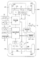
図1は前輪及び後輪に回生制動装置及び摩擦制動装置を有しハイブリッドエンジンが搭載された前輪駆動式の車輌に適用された本発明による制動力制御装置の第一の実施形態を示す概略構成図である。
【0025】
図1に於いて、10は前輪を駆動するハイブリッドエンジンを示しており、ハイブリッドエンジン10はガソリンエンジン12と電動発電機14とを含んでいる。ガソリンエンジン12の出力軸16はクラッチを内蔵する無段変速機18の入力軸に連結されており、無段変速機18の入力軸は電動発電機14の出力軸20にも連結されている。無段変速機18の出力軸19の回転はフロントディファレンシャルギヤ装置22を介して左右前輪用車軸24FL及び24FRへ伝達され、これにより左右の前輪24FL及び24FRが回転駆動される。
【0026】
ハイブリッドエンジン10のガソリンエンジン12及び電動発電機14はエンジン制御装置28により運転者による図には示されていないアクセルペダルの踏み込み量及び車輌の走行状況に応じて制御される。また電動発電機14は前輪用回生制動装置30の発電機としても機能し、回生発電機としての機能(回生制動)もエンジン制御装置28により制御される。
【0027】
特に図示の実施形態に於いては、ハイブリッドエンジン10は図には示されていないシフトレバーがDレンジにある通常走行時にはガソリンエンジン12又はガソリンエンジン12と電動発電機14とにより駆動力又はエンジンブレーキ力を発生し(通常運転モード)、シフトレバーがDレンジにあるが負荷が低いときには電動発電機14のみにより駆動力を発生し(電気自動車モード)、シフトレバーがBレンジにあるときにもガソリンエンジン12と電動発電機14とにより駆動力又はエンジンブレーキ力を発生するが、その場合のエンジンブレーキ力はDレンジの場合よりも高く(エンジンブレーキモード)、シフトレバーがDレンジにあり運転者によりブレーキペダル32が踏み込まれたときにも電動発電機14は回生発電機として機能する。
【0028】
また図1に於いて、従動輪である左右の後輪34RL及び34RRの回転は左右後輪用車軸36RL、36RR及び後輪用ディファレンシャルギヤ装置38を介して後輪用回生制動装置40の電動発電機42へ伝達されるようになっている。電動発電機42による回生制動もエンジン制御装置28により制御され、従ってエンジン制御装置28は回生制動装置用制御装置として機能する。
【0029】
左右の前輪26FL、26FR及び左右の後輪34RL、34RRの摩擦制動力は摩擦制動装置44の油圧回路46により対応するホイールシリンダ48FL、48FR、48RL、48RRの制動圧が制御されることによって制御される。図には示されていないが、油圧回路46はリザーバ、オイルポンプ、種々の弁装置等を含み、各ホイールシリンダの制動圧力は通常時には運転者によるブレーキペダル32の踏み込み量及びブレーキペダル32の踏み込みに応じて駆動されるマスタシリンダ50の圧力に応じて摩擦制動装置用制御装置としての制動制御装置52により制御される。
【0030】
エンジン制御装置28にはアクセルペダルセンサ54よりアクセルペダルの踏み込み量を示す信号、シフトポジションセンサ56より無段変速機18のシフト位置を示す信号、制動制御装置52より前輪の目標回生制動力Fgft及び後輪の目標回生制動力Fgrtを示す信号がそれぞれ入力される。
【0031】
制動制御装置52にはストロークセンサ58よりブレーキペダル32の踏み込みストロークSpを示す信号、圧力センサ60よりマスタシリンダ50の圧力Pmを示す信号、前後加速度センサ62より車輌の前後加速度Gxを示す信号、圧力センサ64fl、64fr、64rl、64rrより左右前輪及び左右後輪のホイールシリンダ48FL、48FR、48RL、48RRの制動圧力Pfl、Pfr、Prl、Prrを示す信号、車輪速度センサ66fl、66fr、66rl、66rrより左右前輪及び左右後輪の車輪速度Vwfl、Vwfr、Vwrl、Vwrrを示す信号がそれぞれ入力される。
【0032】
尚エンジン制御装置28及び制動制御装置52は実際にはそれぞれ例えばCPU、ROM、RAM、入出力装置を含むマイクロコンピュータと駆動回路とを含む一般的な構成のものであってよい。また前後加速度センサ62は車輌の加速方向を正として車輌の前後加速度Gxを検出する。
【0033】
後に詳細に説明する如く、制動制御装置52は後述の如く図2に示されたルーチンに従ってブレーキペダル32の踏み込みストロークSp及びマスタシリンダ圧力Pmに基づき運転者の制動要求量である車輌の最終目標減速度Gbtを演算し、最終目標減速度Gbt及び所定の前後輪制動力配分比に基づき前輪及び後輪の目標制動力Fbft及びFbrtを演算し、回生制動装置30及び40の最大回生制動力をそれぞれFgfmax、Fgrmaxとして、目標制動力Fbft及び最大回生制動力Fgfmaxの小さい方の値を前輪の目標回生制動力Fgftとして演算すると共に、目標制動力Fbrt及び最大回生制動力Fgrmaxの小さい方の値を後輪の目標回生制動力Fgrtとして演算し、これらの目標回生制動力を示す信号をエンジン制御装置28へ出力する。
【0034】
エンジン制御装置28は前輪の目標回生制動力Fgftを上限として前輪の回生制動装置30の電動発電機14を制御し、その発電電圧及び発電電流に基づき前輪の回生制動装置30による実際の回生制動力Fgfaを演算する。同様にエンジン制御装置28は後輪の目標回生制動力Fgrtを上限として後輪の回生制動装置40の電動発電機42を制御し、その発電電圧及び発電電流に基づき後輪の回生制動装置40による実際の回生制動力Fgraを演算する。更にエンジン制御装置28は前輪及び後輪の実際の回生制動力Fgfa及びFgraを示す信号を制動制御装置52へ出力する。
【0035】
制動制御装置52は、目標制動力Fbftより実際の回生制動力Fgfaを減算した値を前輪の目標摩擦制動力Fpftとして演算し、また目標制動力Fbrtより実際の回生制動力Fgraを減算した値を後輪の目標摩擦制動力Fprtとして演算し、前輪の目標摩擦制動力Fpftに基づき左右前輪の目標制動圧力Pbtfl及びPbtfrを演算し、また後輪の目標摩擦制動力Fprtに基づき左右後輪の目標制動圧力Pbtrl及びPbtrrを演算し、左右前輪及び左右後輪の制動圧力Pi(i=fl、fr、rl、rr)がそれぞれ対応する目標制動圧力Pbti(i=fl、fr、rl、rr)になるよう各車輪の制動圧力を制御する。
【0036】
また制動制御装置52は、各車輪の車輪速度Vwi(i=fl、fr、rl、rr)に基づき当技術分野に於いて公知の要領にて車体速度Vb及び各車輪の制動スリップ量SLi(i=fl、fr、rl、rr)を演算し、何れかの車輪の制動スリップ量SLiがアンチスキッド制御(ABS制御)開始の基準値であるSLa(正の定数)よりも大きくなり、アンチスキッド制御の開始条件が成立すると、アンチスキッド制御の終了条件が成立するまで、当該車輪について制動スリップ量が所定の範囲内になるようホイールシリンダ内の圧力を増減するアンチスキッド制御を行い、左右前輪の少なくとも一方についてアンチスキッド制御が行われているときには前輪の目標回生制動力Fgftを0に設定し、左右後輪の少なくとも一方についてアンチスキッド制御が行われているときには後輪の目標回生制動力Fgrtを0に設定する。
【0037】
また制動制御装置52は、通常時には目標回生制動力Fgft、Fgrtに基づく回生制動及び目標制動力Fbft、Fbrtに基づく摩擦制動の両者による協調制動モードにより前輪及び後輪の制動力を制御するが、アンチスキッド制御の如く左右前輪の少なくとも一方若しくは左右後輪の少なくとも一方の制動力が個別に制御されるときには、それぞれ前輪若しくは後輪の制動力を摩擦制動のみによる単独制動モードにて制御する。
【0038】
この場合制動制御装置52は、アンチスキッド制御の開始の虞れが高い場合の如く、各車輪の制動力を個別に制御する必要が生じる虞れがあるときには、目標回生制動力Fgft、Fgrtを0まで漸減することにより制動力の制御モードを協調制動モードより単独制動モードへ移行させ、逆に各車輪の制動力の個別制御が完了したときには、目標回生制動力Fgft、Fgrtを漸増することにより制動力の制御モードを単独制動モードより協調制動モードへ移行させる。
【0039】
特に図示の第一の実施形態に於いては、制動制御装置52は、初回の制動制御時又は所定の回数目の制動制御時には全ての車輪の制動力を単独制動モードにて制御し、その際の運転者の制動操作量に基づき車輌の基準減速度Gbtの所定サイクル分の平均値Gbtaを演算すると共に、車輌の実際の減速度Gbxの所定サイクル分の平均値Gbxaを演算し、平均値Gbxaに対する平均値Gbtaの比を目標摩擦制動力Fpft、Fprtに対する補正係数Kpとして演算する。
【0040】
そして制動制御装置52は目標摩擦制動力Fpft、Fprtに補正係数Kpを乗算することにより目標摩擦制動力を補正する。尚摩擦制動装置の四輪のマクロ値として見た摩擦材の設計摩擦係数をμdとし、実際の摩擦係数をμaとすると、補正係数Kpはμd/μaに対応する値であり、従って設計摩擦係数μdに対する実際の摩擦係数μaの低下を摩擦制動力の増大によって補償するための係数である。
【0041】
尚エンジン制御装置28によるハイブリッドエンジン10の運転モードの制御及びガソリンエンジン12の制御は本発明の要旨をなすものではなく、これらの制御は当技術分野に於いて公知の任意の要領にて実施されてよい。
【0042】
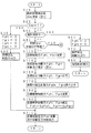
次に図2乃至図5に示されたフローチャートを参照して図示の実施形態に於ける制動制御装置52による制動力制御ルーチンについて説明する。尚図2乃至図5示されたフローチャートによる制御は図には示されていないイグニッションスイッチの閉成により開始され、所定の時間毎に繰返し実行される。
【0043】
まずステップ10に於いては図3に示されたフローチャートに従って運転者の要求制動量である車輌の最終目標減速度Gbtが演算され、ステップ20に於いては最終目標減速度Gbtが0であるか否かの判別、即ち運転者の制動要求がないか否かの判別が行われ、否定判別、即ち運転者が制動を欲している旨の判別が行われたときにはステップ50へ進み、肯定判別が行われたときにはステップ30へ進む。
【0044】
ステップ30に於いては前輪及び後輪の目標回生制動力Fgft及びFgrtが0に設定されると共に、前輪及び後輪の目標摩擦制動力Fpft及びFprtが0に設定され、ステップ40に於いては前輪及び後輪の目標回生制動力Fgft及びFgrt(=0)を示す信号がエンジン制御装置28へ出力され、しかる後ステップ200へ進む。
【0045】
ステップ50に於いてはアンチスキッド制御の如く各車輪の制動力が個別に制御されているか否かの判別が行われ、否定判別が行われたときにはステップ90へ進み、肯定判別が行われたときにはステップ60に於いて前輪及び後輪の目標回生制動力Fgft及びFgrtが0に設定され、ステップ70に於いて前輪及び後輪の目標回生制動力Fgft及びFgrt(=0)を示す信号がエンジン制御装置28へ出力され、ステップ80に於いてアンチスキッド制御の如き個別制御の目標制御量に基づき各車輪の制動力が個別に制御され、しかる後ステップ10へ戻る。
【0046】
ステップ90に於いては上記ステップ20の判別が否定判別より肯定判別になるまでを一回の制動制御とカウントすることとして、今回の制動制御がイグニッションスイッチがオンに切り替えられてから初回の制動制御又はN回目(Nは例えば20、40、60…)の制動制御であるか否かの判別、即ち目標摩擦制動力を補正するための補正係数Kpの演算及び更新が必要であるか否かが行われ、肯定判別が行われたときにはステップ220へ進み、否定判別が行われたときにはステップ100へ進む。
【0047】
ステップ100に於いてはKf及びKrをそれぞれ前輪及び後輪に対する制動力の配分比(正の係数)として、前輪の目標制動力Fbft及び後輪の目標制動力Fbrtがそれぞれ下記の式1及び2に従って演算される。
Fbft=Kf・Gt ……(1)
Fbrt=Kr・Gt ……(2)
【0048】
ステップ110に於いては図4に示されたフローチャートに従って前輪の目標回生制動力Fgft及び後輪の目標回生制動力Fgrtが演算されると共に補正され、ステップ160に於いては補正後の目標回生制動力Fgft及びFgrtを示す信号がエンジン制御装置28へ出力される。
【0049】
ステップ170に於いては後述の如くエンジン制御装置28による回生制動制御により達成された実際の前輪の回生制動力Fgfa及び実際の後輪の回生制動力Fgraを示す信号がエンジン制御装置28より読み込まれ、ステップ180に於いては前輪の目標摩擦制動力Fpft及び後輪の目標摩擦制動力Fprtがそれぞれ下記の式3及び4に従って演算される。
Fpft=Fbft−Fgfa ……(3)
Fprt=Fbrt−Fgra ……(4)
【0050】
ステップ190に於いては前輪の目標摩擦制動力Fpft及び後輪の目標摩擦制動力Fprtにそれぞれ補正係数Kpが乗算されることにより、補正後の前輪の目標摩擦制動力Fpft及び後輪の目標摩擦制動力Fprtが演算される。
【0051】
ステップ210に於いては前輪の目標摩擦制動力Fpftに基づき左右前輪の目標制動圧力Pbtfl及びPbtfrが演算され、また後輪の目標摩擦制動力Fprtに基づき左右後輪の目標制動圧力Pbtrl及びPbtrrが演算されると共に、左右前輪及び左右後輪の制動圧力Piがそれぞれ対応する目標制動圧力Pbtiになるよう各車輪の制動圧力が圧力フィードバックにより制御され、しかる後ステップ10へ戻る。
【0052】
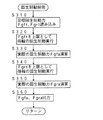
図5に示されている如く、ステップ220に於いては前輪及び後輪の目標回生制動力Fgft及びFgrtが0に設定され、ステップ230に於いては前輪及び後輪の目標回生制動力Fgft及びFgrt(=0)を示す信号がエンジン制御装置28へ出力され、ステップ240に於いては前輪の目標摩擦制動力Fpft及び後輪の目標摩擦制動力Fprtがそれぞれ前輪の目標制動力Fbft及び後輪の目標制動力Fbrtに設定される。
【0053】
ステップ250に於いては上記ステップ210の場合と同様、前輪の目標摩擦制動力Fpftに基づき左右前輪の目標制動圧力Pbtfl及びPbtfrが演算され、また後輪の目標摩擦制動力Fprtに基づき左右後輪の目標制動圧力Pbtrl及びPbtrrが演算されると共に、左右前輪及び左右後輪の制動圧力Piがそれぞれ対応する目標制動圧力Pbtiになるよう各車輪の制動圧力が圧力フィードバックにより制御される。
【0054】
ステップ260に於いては前後加速度センサ62により検出された車輌の前後加速度Gxを示す信号の読み込みが行われると共に、前後加速度Gxに基づき車輌の減速度Gbxが−Gxとされる。
【0055】
ステップ270に於いては現在まで所定サイクル分の最終目標減速度Gbt及び実際の減速度Gbxのデータが蓄積されたか否かの判別、即ち目標摩擦制動力に対する補正係数Kpの演算が可能であるか否かの判別が行われ、否定判別が行われたときにはステップ10へ戻り、肯定判別が行われたときにはステップ280に於いて現在までの所定サイクル分の最終目標減速度Gbtの平均値Gbta及び現在までの所定サイクル分の車輌の実際の減速度Gbx(=−Gx)の平均値Gbxaが演算されると共に、下記の式5に従って目標摩擦制動力に対する補正係数Kpが演算される。
Kp=Gbta/Gbxa ……(5)
【0056】
図3に示された車輌の最終目標減速度Gbt演算ルーチンのステップ12に於いてはストロークセンサ58により検出されたブレーキペダル32の踏み込みストロークSpを示す信号及び圧力センサ60により検出されたマスタシリンダ50の圧力Pmを示す信号の読み込みが行われ、ステップ14に於いては図12に示されたグラフに対応するマップより踏み込みストロークSpに基づく車輌の目標減速度Gstが演算され、ステップ16に於いては図13に示されたグラフに対応するマップよりマスタシリンダ圧力Pmに基づく車輌の目標減速度Gptが演算される。
【0057】
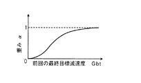
ステップ18に於いては前サイクルに於いて演算された最終目標減速度Gbtに基づき図14に示されたグラフに対応するマップよりマスタシリンダ圧力Pmに基づく目標減速度Gptに対する重みα(0≦α≦1)が演算されると共に、下記の式6に従って目標減速度Gpt及び目標減速度Gstの重み付け和として車輌の最終目標減速度Gbtが演算される。
Gbt=α・Gpt+(1−α)Gst ……(6)
【0058】
また図4に示された目標回生制動力演算ルーチンのステップ112に於いては前輪の目標回生制動力Frgft及び後輪の目標回生制動力Frgrtがそれぞれ下記の式6及び7に従って演算される。尚下記の式7及び8に於けるMINは( )内の数値の小さい方を選択することを意味する。また最大回生制動力Fgfmax及びFgrmaxはそれぞれ正の定数であってよいが、ハイブリッドエンジン10の運転モードや車速に応じて可変設定されてもよい。
Fgft=MIN(Fbft,Fgfmax) ……(7)
Fgrt=MIN(Fbrt,Fgrmax) ……(8)
【0059】
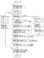
ステップ116に於いては前輪が協調制動モードより単独制動モードへの移行中であるか又は例えば左右前輪の少なくとも一方についてアンチスキッド制御が開始される虞れがあり上記モードの移行が必要な状況であるか否かの判別が行われ、否定判別が行われたときにはステップ124へ進み、肯定判別が行われたときにはステップ118へ進む。
【0060】
ステップ118に於いては前輪の目標回生制動力Fgftが基準値Ffo(0に近い正の定数)未満であるか否かの判別、即ち前輪の目標回生制動力Fgftの漸減が完了したか否かの判別が行われ、否定判別が行われたときにはステップ120に於いてFgftfを前輪の目標回生制動力の前回値とし、ΔFfを微小な正の定数として前輪の目標回生制動力FgftがFgftf−ΔFfに設定され、肯定判別、即ち協調制動モードより単独制動モードへの移行が完了した旨の判別が行われたときにはステップ122に於いて前輪の目標回生制動力Fgftが0に設定される。
【0061】
ステップ124に於いては前輪が単独制動モードより協調制動モードへの移行中であるか又は例えばアンチスキッド制御が実行されていたときにはそのアンチスキッド制御が終了し上記モードの移行が必要な状況であるか否かの判別が行われ、肯定判別が行われたときにはステップ130へ進み、否定判別が行われたときにはステップ126へ進む。
【0062】
ステップ126に於いては前輪が単独制動モードにて制動制御されているか否かの判別が行われ、肯定判別が行われたときにはステップ128に於いて前輪の目標回生制動力Fgftが0に設定され、否定判別、即ち前輪が協調制動モードにて制動制御されている旨の判別が行われたときにはそのままステップ136へ進む。
【0063】
ステップ130に於いては前輪の前回の目標制動力Fbftfと前輪の前回の目標回生制動力Fgftfとの偏差ΔFgft(=Fbftf−Fgftf)が演算されると共に、偏差ΔFgftが基準値ΔFfo(正の定数)未満であるか否かの判別、即ち前輪の目標回生制動力Fgftの漸増が完了したか否かの判別が行われ、否定判別が行われたときにはステップ132に於いて前輪の目標回生制動力FgftがΔFfインクリメントされ、肯定判別、即ち単独制動モードより協調制動モードへの移行が完了した旨の判別が行われたときにはそのままステップ136へ進む。
【0064】
ステップ136〜152に於いては前輪の目標回生制動力Fgftが後輪の目標回生制動力Fgrtに置き換えられ、前輪の前回の目標回生制動力Fgftfが後輪の前回の目標回生制動力Fgrtfに置き換えられ、偏差ΔFgftが後輪の前回の目標制動力Fbrtfと後輪の前回の目標回生制動力Fgrtfとの偏差(=Fbrtf−Fgrtf)に置き換えられ、基準値Ffo及びΔFfoがそれぞれ基準値値Fro及びΔFro(何れも0に近い正の定数)に置き換えられ、増減量ΔFfが増減量ΔFr(微小な正の定数)に置き換えられる点を除き、それぞれ上述のステップ116〜132の場合と同様の要領にて後輪の目標回生制動力Fgrtが補正される。
【0065】
次に図6に示されたフローチャートを参照して図示の実施形態に於けるエンジン制御装置28による回生制動制御ルーチンについて説明する。尚図6に示されたフローチャートによる制御も図には示されていないイグニッションスイッチの閉成により開始され、所定の時間毎に繰返し実行される。
【0066】
まずステップ310に於いては制動制御装置52より前輪の目標回生制動力Fgft及び後輪の目標回生制動力Fgrtを示す信号の読み込みが行われ、ステップ320に於いては目標回生制動力Fgftを上限として前輪の回生制動装置30による回生制動が実行され、ステップ330に於いては前輪の回生制動装置30による前輪の実際の回生制動力Fgfaが演算される。
【0067】
同様にステップ340に於いては目標回生制動力Fgrtを上限として後輪の回生制動装置40による回生制動が実行され、ステップ350に於いては後輪の回生制動装置40による後輪の実際の回生制動力Fgraが演算され、ステップ360に於いては前輪の実際の回生制動力Fgfa及び後輪の実際の回生制動力Fgraを示す信号が制動制御装置52へ出力され、しかる後ステップ310へ戻る。
【0068】
かくして図示の第一の実施形態によれば、ステップ20に於いてブレーキペダル32の踏み込みストロークSp及びマスタシリンダ圧力Pmに基づき車輌の最終目標減速度Gbt、即ち運転者の制動操作量に基づく車輌の基準減速度が演算される。
【0069】
そしてステップ100に於いて所定の前後輪制動力配分比及び最終目標減速度Gbtに基づき前輪の目標制動力Fbft及び後輪の目標制動力Fbrtが演算され、ステップ110に於いて前輪の目標回生制動力Fgftが目標制動力Fbft及び最大回生制動力Fgfmaxの小さい方の値として演算されると共に、後輪の目標回生制動力Fgrtが目標制動力Fbrt及び最大回生制動力Fgrmaxの小さい方の値として演算され、ステップ160に於いてこれらの目標回生制動力を示す信号がエンジン制御装置28へ出力される。
【0070】
また図6に示された回生制動ルーチンのステップ320に於いてエンジン制御装置28により前輪の目標回生制動力Frgftを上限として前輪の回生制動装置30の電動発電機14が制御され、ステップ330に於いて電動発電機14の発電電圧及び発電電流に基づき前輪の回生制動装置30による実際の回生制動力Frgfaが演算され、またステップ340に於いてエンジン制御装置28により後輪の目標回生制動力Frgrtを上限として後輪の回生制動装置40の電動発電機42が制御され、ステップ350に於いて電動発電機42の発電電圧及び発電電流に基づき後輪の回生制動装置40による実際の回生制動力Frgraが演算される。
【0071】
またステップ170及び180に於いて前輪の目標摩擦制動力Fpftが目標制動力Fbftより実際の回生制動力Fgfaを減算した値として演算されると共に、後輪の目標摩擦制動力Fprtが目標制動力Fbrtより実際の回生制動力Fgraを減算した値として演算され、ステップ210に於いて前輪の目標摩擦制動力Fpftに基づき左右前輪の目標制動圧力Pbtfl及びPbtfrが演算され、後輪の目標摩擦制動力Fprtに基づき左右後輪の目標制動圧力Pbtrl及びPbtrrが演算されると共に、左右前輪及び左右後輪の制動圧力Piがそれぞれ対応する目標制動圧力Pbtiになるよう各車輪の制動圧力がフィードバック制御される。
【0072】
また上述の如く、通常時には各車輪の制動力は回生制動及び摩擦制動による協調制動モードにて制御されるが、アンチスキッド制御が実行される場合の如く、前輪及び後輪の各々について車輪の制動力が個別に制御されるときには、ステップ50に於いて肯定判別が行われ、ステップ60〜80が実行されることにより制動力制御モードが摩擦制動のみによる単独制動モードに切り換えられ、各車輪の制動力が個別に制御される。
【0073】
この場合各車輪の制動力を個別に制御する必要が生じると、ステップ110に於いて、即ちステップ112〜152に於いて目標回生制動力Fgft、Fgrtが0まで漸減されることにより制動力の制御モードが協調制動モードより単独制動モードへ移行され、逆に各車輪の制動力の個別制御が完了したときには、目標回生制動力Fgft、Fgrtが漸増されることにより制動力の制御モードが単独制動モードより協調制動モードに戻される。
【0074】
特に図示の第一の実施形態に於いては、制動力の制御が初回又はN回目であるときには、ステップ90に於いて肯定判別が行われ、図5のステップ220〜280が実行されることにより、摩擦制動による単独制動モードにて制動力が制御され、その際の所定サイクル分の最終目標減速度Gbtの平均値Gbta及び所定サイクル分の車輌の実際の減速度Gbxの平均値Gbxaが演算され、Gbxaに対するGbtaの比として目標摩擦制動力Fpft、Fprtに対する補正係数Kpが演算され、ステップ190に於いて目標摩擦制動力Fpft、FprtがそれぞれKp倍されることにより補正される。
【0075】
従って例えば摩擦制動装置の摩擦材の摩擦係数が低下することにより、目標摩擦制動力に対し実際に発生される摩擦制動力が低くなる状況が生じても、目標摩擦制動力Fpft、FprtがKp倍されることによって本来の目標摩擦制動力に対応する摩擦制動力が発生されるので、制動力の制御モードに拘らず車輌全体の制動力を運転者の制動操作量に正確に対応する値に制御することができ、制動力の制御モードが協調制動モードと単独制動モードとの間に移行する場合にも、車輌全体の制動力が変動することを確実に防止し、これにより車輌の乗員が違和感を感じることを確実に防止することができる。
【0076】
また図示の第一の実施形態によれば、摩擦制動装置の摩擦材の摩擦係数μaがその設計摩擦係数μdに対し低下すると、目標摩擦制動力Fpft、FprtがKp=μd/μa倍に増大され、これにより摩擦制動力が本来あるべき値にて発生されるので、車輌の総制動力は摩擦材の経時変化に拘わらず常に運転者の制動操作量に正確に対応する値、即ち摩擦材の摩擦係数の低下がない場合の値になり、従って後述の第二の実施形態の場合に比して適正に車輪の制動力を制御することができる。
【0077】
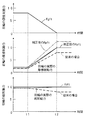
例えば図15は前輪が協調制動モードより摩擦制動による単独制動モードへ移行する場合に於ける第一の実施形態の作動を従来の場合と比較して示すグラフである。
【0078】
図15に於いて、運転者の制動操作量が一定であり、前輪の目標制動力Fbftが10(単位は任意)であり、時点t1まで前輪の制動力が協調制動モードにて制御され、時点t1よりt2までの間に於いて制御モードが協調制動制動モードより単独制動モードへ移行し、時点t2以降に於いては前輪の制動力が単独制動モードにて制御されるものとする。
【0079】
また協調制動モードに於ける目標回生制動力Fgftは8であり、従って前輪の目標摩擦制動力Fpftは2であり、前後輪の摩擦制動装置の摩擦材の摩擦係数μaがその設計値μdの80%に低下しているとすると、協調制動モードに於ける前輪の実際の摩擦制動力は2×0.8=1.6になり、単独制動モードに於ける前輪の実際の摩擦制動力は10×0.8=8になり、前輪の実際の摩擦制動力は図15の中段に於いて破線にて示されている如く変化し、その結果前輪の総制動力は図15の下段の破線にて示されている如く変動し、これにより車輌の減速度も運転者の制動操作量に対応する基準の減速度の80%になる。
【0080】
従って従来の制動力制御装置の場合には、制動モードが協調制動モードより単独制動モードへ移行する過程に於いて前輪の実際の摩擦制動力は1.6より8へ漸次増大すると共に、回生制動力が8より0に漸次減少し、そのため前輪の総制動力は9.6より8に減少し、これに起因して時点t1とt2との間の制動モードの移行中に車輌の減速度が急変する。
【0081】
これに対し図示の第一の実施形態によれば、単独制動モードに於ける所定サイクル分の実際の減速度の平均値Gbxaに対する所定サイクル分の最終目標減速度の平均値Gbtaの比として補正係数Kpが演算され、補正係数Kpは1/0.8=1.25になり、図15の中段の二点鎖線にて示されている如く、前輪の目標摩擦制動力Fpftは1.25倍に補正される。
【0082】
従って前輪の目標摩擦制動力Fpftは協調制動モードに於いては2×1.25=2.5になり、単独制動モードに於いては10×1.25=12.5になり、協調制動モードより単独制動モードへ移行する過程に於いて2.5より12.5まで漸次増大し、これにより前輪の実際の摩擦制動力は協調制動モードに於いては2.5×0.8=2となり、単独制動モードに於いては12.5×0.8=10となり、その目標値と同一になる。よって前輪の総制動力はその目標値と同一の10(一定)となり、従って制動モードが協調制動モードより単独制動モードへ移行する際にも車輌の減速度が変動することを確実に防止することができる。
【0083】
第二の実施形態
図7は前輪及び後輪に回生制動装置及び摩擦制動装置を有しハイブリッドエンジンが搭載された前輪駆動式の車輌に適用された本発明による制動力制御装置の第二の実施形態に於ける制動力制御のメインルーチンを示すフローチャート、図8は目標回生制動力Fgft、Fgrtの演算及び補正ルーチンを示すフローチャート、図9は補正係数Kg演算ルーチンを示すフローチャートである。尚図7乃至図9に於いて、それぞれ図2、図4、図5に示されたステップに対応するステップにはこれらの図に於いて付されたステップ番号と同一のステップ番号が付されている。
【0084】
この第二の実施形態に於いては、第一の実施形態のステップ190に対応する目標摩擦制動力の補正は行われず、またステップ90に於いて肯定判別が行われると、図9に示されたステップ220〜290が実行される。特にステップ270に於いて現在まで所定サイクル分の最終目標減速度Gbt及び実際の減速度Gbxのデータが蓄積されたか否かの判別、即ち目標回生制動力に対する補正係数Kgの演算が可能であるか否かの判別が行われ、否定判別が行われたときにはステップ10へ戻り、肯定判別が行われたときにはステップ290に於いて現在までの所定サイクル分の最終目標目標減速度Gbtの平均値Gbta及び現在までの所定サイクル分の車輌の実際の減速度Gbxの平均値Gbxaが演算されると共に、下記の式9に従って目標回生制動力に対する補正係数Kgが演算される。
【0085】
Kg=Gbxa/Gbta ……(9)
またこの実施形態に於いては、図8に示されている如く、目標回生制動力の演算及び補正ルーチンのステップ112が完了すると、ステップ114に於いて前輪及び後輪の目標回生制動力Fgft及びFgrtがそれぞれKg倍に補正され、しかる後第一の実施形態の場合と同様ステップ116〜152が実行される。
【0086】
かくしてこの第二の実施形態によれば、基本的な制動力の制御は上述の第一の実施形態の場合と同様に行われるが、制動力の制御が初回又はN回目であるときには、ステップ90に於いて肯定判別が行われ、図5のステップ220〜290が実行されることにより、摩擦制動による単独制動モードにて制動力が制御され、その際の所定サイクル分の最終目標減速度Gbtの平均値Gbta及び所定サイクル分の車輌の実際の減速度Gbxの平均値Gbxaが演算され、Gbtaに対するGbxaの比として目標回生制動力Fgft、Fgrtに対する補正係数Kgが演算され、ステップ110、より詳細には図8のステップ114に於いて目標回生制動力Fgft、FgrtがそれぞれKg倍されることにより補正される。
【0087】
従って例えば摩擦制動装置の摩擦材の摩擦係数が低下することにより、目標摩擦制動力に対し実際に発生される摩擦制動力が低くなる状況が生じても、目標回生制動力Fgft、FgrtがKg倍されることによって協調制動モード及び制動モードの移行中に於ける回生制動力が低減されるので、制動力の制御モードに拘らず車輌全体の制動力を運転者の制動操作量に対応する値に制御することができ、制動力の制御モードが協調制動モードと単独制動モードとの間に移行する場合にも、車輌全体の制動力が変動することを確実に防止し、これにより車輌の乗員が違和感を感じることを確実に防止することができる。
【0088】
例えば図16は前輪が協調制動モードより摩擦制動による単独制動モードへ移行する場合に於ける第二の実施形態の作動を従来の場合と比較して示す図15と同様のグラフである。
【0089】
図15の場合と同様、前後輪の摩擦制動装置の摩擦材の摩擦係数μaがその設計値μdの80%に低下しているとすると、補正係数Kgは0.8になり、図16の上段に於いて二点鎖線にて示されている如く、前輪の目標回生制動力は協調制動モードに於いては8×0.8=6.4になり、単独制動モードへ移行する過程に於いて0まで漸次減少する。
【0090】
従って前輪の実際の回生制動力が前輪の目標回生制動力と同一であると仮定すると、前輪の実際の摩擦制動力は図15の下段に於いて細い実線にて示されている如く、協調制動モードに於いては6.4+1.6=8であり、単独制動モードに於いては10×0.8=8であり、その結果前輪の総制動力は制動モードに拘わらず8(一定)であり、これにより車輌の減速度も運転者の制動操作量に対応する基準の減速度の80%の一定になり、従って制動モードが協調制動モードより単独制動モードへ移行する際にも車輌の減速度が変動することを確実に防止することができる。
【0091】
第三の実施形態
図10は第一の実施形態の修正例として構成された本発明による制動力制御装置の第三の実施形態に於ける制動力制御のメインルーチンを示すフローチャート、図11は目標摩擦制動力Fpft、Fprtの補正ルーチンを示すフローチャートである。尚図10に於いて、図2に示されたステップに対応するステップには図2に於いて付されたステップ番号と同一のステップ番号が付されている。
【0092】
この第三の実施形態に於いては、ステップ190の次に実行されるステップ200に於いて、図11に示されたルーチンに従って前輪の目標摩擦制動力Fpft若しくは後輪の目標摩擦制動力Fprtが補正される点を除き、他のステップは上述の第一の実施形態の場合と同様に実行される。
【0093】
特に図11に示されている如く、目標摩擦制動力補正ルーチンのステップ202に於いては、前輪が協調制動モードにて制御されているか否かの判別、即ち単独制動モードでもモードの移行状態にもないか否かの判別が行われ、肯定判別が行われたときにはそのままステップ206へ進み、否定判別が行われたときにはステップ204に於いて前輪の目標摩擦制動力FpftがKp倍に補正される。
【0094】
同様にステップ206に於いては後輪が協調制動モードにて制御されているか否かの判別が行われ、肯定判別が行われたときにはそのままステップ210へ進み、否定判別が行われたときにはステップ208に於いて後輪の目標摩擦制動力FprtがKp倍に補正され、しかる後ステップ210へ進む。
【0095】
かくしてこの第三の実施形態によれば、制動モードが単独制動モードにある場合又は協調制動モードより単独制動モードへ移行する過程に於いてのみ目標摩擦制動力Fpft、FprtがKp倍に補正されることにより、制動モードが協調制動モードより単独制動モードへ移行する過程に於ける総制動力の急変が防止されるので、制動モードが協調制動モードより単独制動モードへ移行する際に車輌の減速度が変動することを効果的に防止することができる。
【0096】
例えば図17は前輪が協調制動モードより摩擦制動による単独制動モードへ移行する場合に於ける第三の実施形態の作動を従来の場合と比較して示す図15と同様のグラフである。
【0097】
図15及び図16の場合と同様、前後輪の摩擦制動装置の摩擦材の摩擦係数μaがその設計値μdの80%に低下しているとすると、補正係数Kpは1.25になり、図17の中段に於いて二点鎖線にて示されている如く、前輪の目標摩擦生制動力は時点t1以降に1.25倍に補正され、単独制動モードに於いては10×1.25=12.5になり、協調制動モードより単独制動モードへ移行する過程に於いて2より12.5まで漸次増大する。
【0098】
従って前輪の実際の回生制動力が前輪の目標回生制動力と同一であると仮定すると、前輪の実際の摩擦制動力は図15の下段に於いて細い実線にて示されている如く、協調制動モードに於いては2であり、単独制動モードに於いては12.5×0.8=10になり、協調制動モードより単独制動モードへ移行する過程に於いて2より10まで漸次増大し、図17の中段に於いて太い実線にて示された目標摩擦制動力と同一の値になる。その結果前輪の総制動力は協調制動モードより単独制動モードへ移行する過程に於いて8+1.6=9.6より10までしか変化せず、従来の場合の9.6より8まで変化する場合に比してその変化量を大幅に低減することができ、これにより制動モードが協調制動モードより単独制動モードへ移行する際に車輌の減速度が急激に変動することを効果的に防止することができる。
【0099】
尚上述の各実施形態に於いて、制動制御モードが単独制動モードより協調制動モードへ移行する場合には、時間の経過がそれぞれ図15乃至図17の場合とは逆であり、従って各制動力が図15乃至図17の場合とは逆の態様にて変化する点を除き同一であり、従って上述の各実施形態によれば、制動制御モードが単独制動モードより協調制動モードへ移行する際にも車輌の減速度が変動することを確実に防止することができる。
【0100】
また以上の説明に於ける具体例は摩擦制動装置の摩擦材の摩擦係数μaがその設計値μdよりも低下している場合であるが、上述の各実施形態によれば、摩擦材の摩擦係数μaがその設計値μdよりも大きい場合にも、制動制御モードが単独制動モードより協調制動モードへ移行する際に於ける車輌の減速度の急変を確実に防止することができる。尚この場合、補正係数Kpは1よりも小さい値になり、逆に補正係数Kgは1よりも大きい値になる。
【0101】
また図示の各実施形態によれば、初回の制動制御又はN回目の制動制御時に各車輪の制動力が摩擦制動による単独制動モードにて制御され、その際の運転者の制動操作量に基づく車輌の基準減速度及び車輌の実際の減速度に基づき補正係数Kp又はKgが演算され、目標摩擦制動力がKp倍されることによって補正され又は目標回生制動力がKg倍されることによって補正され、これにより制動力の制動モードが協調制動モードと単独制動モードとの間に移行する際に於ける車輌の減速度の急変が防止されるので、運転者の制動操作量に基づく車輌の基準減速度と車輌の実際の減速度との偏差に基づき摩擦制動力若しくは回生制動力が毎回フィードバック制御される場合に比して、車輌の制動力を容易に且つ簡便に制御することができ、これにより制動力の制動モードが協調制動モードと単独制動モードとの間に移行する際に於ける車輌の減速度の急変を容易に且つ簡便に防止することができる。
【0102】
また図示の各実施形態によれば、前輪及び後輪の摩擦制動装置による制動力と回生制動装置による制動力との合計及び後輪の摩擦制動装置による制動力と回生制動装置による制動力との合計の比が所定の前後輪制動力配分比Kf/Krになるよう制御されるので、摩擦制動装置による制動力と回生制動装置による制動力との割合に拘わらず前後輪の制動力の配分比を確実に所定の前後輪制動力配分比に制御することができ、これにより前後輪の制動力配分比が所定の配分比以外の配分比になることに起因する車輌の安定性の低下やステア特性の変化を確実に防止することができる。
【0103】
また図示の各実施形態によれば、前輪の目標制動力Fbftは前輪の回生制動装置による制動力が最大になるよう前輪の回生制動力及び摩擦制動力が制御されることによって達成され、後輪の目標制動力Fbrtも後輪の回生制動装置による制動力が最大になるよう後輪の回生制動力及び摩擦制動力が制御されることによって達成されるので、所定の前後輪制動力配分比を達成しつつ車輌全体の回生効率が最大になるよう回生制動力及び摩擦制動力を制御することができる。
【0104】
また一般に、回生制動装置、特にハイブリッドエンジンに組み込まれた電動発電機を使用する回生制動装置は種々の制約からある目標回生制動力にて制御されても実際の回生制動力は目標回生制動力にならず、実際の回生制動力は目標回生制動力よりも低い値になる。
【0105】
図示の各実施形態によれば、それぞれ前輪の目標回生制動力Frgft及び後輪の目標回生制動力Frgrtを上限としてエンジン制御装置28により前輪の回生制動装置30の電動発電機14及び後輪の回生制動装置40の電動発電機42が制御され、各電動発電機の発電電圧及び発電電流に基づき前輪及び後輪の実際の回生制動力Frgfa、Frgraが演算され、前輪の目標摩擦制動力Fbpft及び後輪の目標摩擦制動力Fbprtはそれぞれ目標制動力Fbft、Fbrtより実際の回生制動力Frgfa、Frgraを減算することにより演算されるので、前輪の目標摩擦制動力Fbpft及び後輪の目標摩擦制動力Fbprtがそれぞれ目標制動力Fbft、Fbrtより目標回生制動力Frgft、Frgrtを減算することにより演算される場合に比して、車輌全体の制動力が正確に運転者の制動要求量に対応するよう前輪及び後輪の摩擦制動力を制御をすることができる。
【0106】
以上に於いては本発明を特定の実施形態について詳細に説明したが、本発明は上述の実施形態に限定されるものではなく、本発明の範囲内にて他の種々の実施形態が可能であることは当業者にとって明らかであろう。
【0107】
例えば上述の各実施形態に於いては、車輌の基準減速度合及び車輌の実際の減速度合は車輌の基準減速度Gbt及び車輌の実際の減速度Gbxであるが、車輌の基準減速度合及び車輌の実際の減速度合は所定の時間に於ける車速の変化量の如く、車輌の減速の程度を示す任意の値であってよい。
【0108】
また上述の各実施形態に於いては、目標摩擦制動力又は目標回生制動力がそれぞれKp倍又はKg倍されることにより補正されるようになっているが、目標摩擦制動力及び目標回生制動力の両者が補正係数Kp及びKgに対応する補正係数にて補正されるよう修正されてもよい。
【0109】
また上述の各実施形態に於いては、摩擦制動装置の摩擦材の摩擦係数の変動が大きい場合にも運転者に警報が発せられないが、補正係数Kpがその所定の基準値よりも大きい場合や補正係数Kgがその所定の基準値よりも小さい場合には、摩擦材の摩擦係数の変動が大きい状況であるので、かかる状況に於いて運転者に警報が発せられるよう修正されてもよい。
【0110】
また上述の各実施形態に於いては、制動力制御装置はホイールシリンダ圧力が増減されることにより制動力が増減される油圧式の制動力制御装置であるが、本発明による制動力制御装置は車輪に設けられたブレーキロータの如き回転部材に対しブレーキパッドの如き摩擦部材を押圧する電動機の如き電気式の押圧装置を有する電気式の制動力制御装置に適用されてもよい。
【0111】
また各上述の実施形態に於いては、エンジン制御装置28と制動制御装置52との間に於いて目標回生制動力及び実際の回生制動力が通信されるようになっているが、目標回生制動力に基づき目標回生制動トルクが演算され、その目標回生制動トルクを示す信号が制動制御装置52よりエンジン制御装置28へ通信され、エンジン制御装置28により目標回生制動トルクを上限として回生制動が制御され、逆に実際の回生制動トルクを示す信号がエンジン制御装置28より制動制御装置52へ通信され、実際の回生制動トルクに基づき実際の回生制動力が演算されるよう修正されてもよい。
【0112】
また上述の各実施形態に於いては、ブレーキペダル32の踏み込みストロークSp及びマスタシリンダ圧力Pmに基づき車輌の目標減速度Gbtが演算され、目標減速度に基づき前輪の目標制動力Fbft及び後輪の目標制動力Fbrtが演算されるようになっているが、前輪及び後輪の目標制動力は踏み込みストロークSp又はマスタシリンダ圧力Pmに基づき演算されてもよい。
【0113】
また上述の各実施形態に於いては、車輌を駆動する駆動手段はガソリンエンジン12と電動発電機14とを含むハイブリッドエンジン10であり、電動発電機14が回生制動用の発電機として作動するようになっているが、ハイブリッドエンジンの内燃機関はディーゼルエンジンの如き他の内燃機関であってもよく、また車輌を駆動する駆動手段は通常の内燃機関であり、回生制動用の発電機は内燃機関とは独立のものであってもよい。
【0114】
また上述の各実施形態に於いては、車輌は前輪駆動車であるが、本発明が適用される車輌は後輪駆動車や四輪駆動車であってもよく、また後輪の電動発電機40は回生制動用の発電機としてのみ作動するようになっているが、例えば必要に応じて後輪を駆動する補助的な駆動源として機能するよう修正されてもよい。
【図面の簡単な説明】
【図1】前輪及び後輪に回生制動装置及び摩擦制動装置を有しハイブリッドエンジンが搭載された前輪駆動式の車輌に適用された本発明による制動力制御装置の第一の実施形態を示す概略構成図である。
【図2】第一の実施形態に於ける制動制御装置による制動力制御のメインルーチンを示すフローチャートである。
【図3】ステップ10に於ける最終目標減速度Gbt演算ルーチンを示すフローチャートである。
【図4】ステップ110に於ける目標回生制動力Fgft、Fgrtの補正ルーチンを示すフローチャートである。
【図5】第一の実施形態に於ける目標摩擦制動力に対する補正係数Kp演算ルーチンを示すフローチャートである。
【図6】第一の実施形態に於けるエンジン制御装置による回生制動制御ルーチンを示すフローチャートである。
【図7】本発明による制動力制御装置の第二の実施形態に於ける制動力制御のメインルーチンを示すフローチャートである。
【図8】第二の実施形態に於ける目標回生制動力Fgft、Fgrtの演算及び補正ルーチンを示すフローチャートである。
【図9】第二の実施形態に於ける目標回生制動力に対する補正係数Kg演算ルーチンを示すフローチャートである。
【図10】第一の実施形態の修正例として構成された本発明による制動力制御装置の第三の実施形態に於ける制動力制御のメインルーチンを示すフローチャートである。
【図11】第三の実施形態に於ける目標摩擦制動力Fpft、Fprtの補正ルーチンを示すフローチャートである。
【図12】ブレーキペダルの踏み込みストロークSpと目標減速度Gstとの関係を示すグラフである。
【図13】マスタシリンダ圧力Pmと目標減速度Gptとの関係を示すグラフである。
【図14】前回演算された最終目標減速度Gbtと目標減速度Gptに対する重みαとの関係を示すグラフである。
【図15】前輪が協調制動モードより単独制動モードへ移行する場合に於ける第一の実施形態の作動を従来の場合と比較して示すグラフである。
【図16】前輪が協調制動モードより単独制動モードへ移行する場合に於ける第二の実施形態の作動を従来の場合と比較して示すグラフである。
【図17】前輪が協調制動モードより単独制動モードへ移行する場合に於ける第三の実施形態の作動を従来の場合と比較して示すグラフである。
【符号の説明】
10…ハイブリッドエンジン
12…ガソリンエンジン
14…電動発電機
28…エンジン制御装置
30…前輪の回生制動装置
32…ブレーキペダル
40…後輪用回生制動装置
42…電動発電機
44…摩擦制動装置
50…マスタシリンダ
52…制動制御装置
58…ストロークセンサ
60…圧力センサ
62…前後加速度センサ
64fl〜64rr…圧力センサ
66fl〜66rr…車輪速度センサ[0001]
BACKGROUND OF THE INVENTION
The present invention relates to a vehicle braking control device, and more particularly to a braking control device that performs friction braking by a friction braking device and regenerative braking by a regenerative braking device.
[0002]
[Prior art]
As one of braking control devices for vehicles such as automobiles, for example, as described in Japanese Patent Application Laid-Open No. 2000-50409 relating to the application of the present applicant, a friction braking device and a regenerative braking device are provided. And a braking control device configured to perform braking in the cooperative braking mode by regenerative braking, shift from the cooperative braking mode to the single braking mode by friction braking, and return from the single braking mode to the cooperative braking mode as necessary. Are known.
[0003]
According to such a braking control device, a part of the kinetic energy of the vehicle at the time of braking of the vehicle is recovered as electric energy by regenerative braking under normal conditions, and regenerative braking interferes with other control of the vehicle such as anti-skid control. Therefore, the influence of regenerative braking can be surely eliminated.
[0004]
[Problems to be solved by the invention]
In general, during the braking control in the cooperative braking mode, the target braking amount of the entire vehicle, such as the driver's required braking amount, is distributed to the friction braking target braking amount and the regenerative braking target braking amount. The friction braking device and the regenerative braking device are controlled so that the braking amount of each becomes the corresponding target braking amount.
[0005]
In addition, when shifting from the cooperative braking mode to the single braking mode by friction braking, regenerative braking is performed while maintaining the sum of the target braking amount of friction braking and the target braking amount of regenerative braking equal to the target braking amount of the entire vehicle. The target braking amount is gradually reduced and the frictional braking target braking amount is gradually increased. Finally, the frictional braking target braking amount is set to a value equal to the target braking amount of the entire vehicle. Similarly, when returning from the single braking mode by friction braking to the cooperative braking mode, while maintaining the sum of the target braking amount of friction braking and the target braking amount of regenerative braking equal to the target braking amount of the entire vehicle, The regenerative braking target braking amount is gradually increased and the friction braking target braking amount is gradually decreased until the regenerative braking target braking amount reaches the maximum possible value.
[0006]
However, since the braking by the friction braking device is performed by a frictional force generated by pressing a friction material such as a brake pad against a rotating body such as a brake rotor that rotates with a wheel, the friction characteristics of the rotating body or the friction material, In particular, when the friction coefficient is different from the design value, the actual friction braking amount does not accurately become the target braking control amount no matter how accurately the pressing force of the friction material against the rotating body is controlled.
[0007]
The error in the actual friction braking amount of the entire vehicle due to the deviation of the frictional characteristics of the rotating body or the friction material is small in the situation where the braking is performed in the cooperative braking mode, but the single braking between the cooperative braking mode and the friction braking is independent. When shifting between braking modes, the braking amount of the entire vehicle changes abruptly when shifting between the cooperative braking mode and the single braking mode. As a result, the deceleration of the vehicle fluctuates abruptly, and the vehicle occupant may feel uncomfortable.
[0008]
For example, it is assumed that the target braking amount of the entire vehicle in the cooperative braking mode is 10, and the ratio of the friction braking target braking amount and the regenerative braking target braking amount is 1: 9, which is caused by the deviation of the friction characteristics of the friction material. Assuming that the deviation amount of the actual friction braking amount is 10%, the error of the actual friction braking amount of the entire vehicle in the cooperative braking mode is 0.1 × 0.1 = 0.01, which is 1%. On the other hand, the error of the actual friction braking amount of the entire vehicle in the single braking mode is 1 × 0.1 = 0.1, which is 10%.
[0009]
The present invention relates to a conventional braking control device configured to perform braking in a cooperative braking mode by friction braking and regenerative braking at a normal time and shift between a cooperative braking mode and a single braking mode by friction braking as necessary. The main problems of the present invention are as follows.The preset number of times of brakingBy friction braking onlyIn single braking mode,By correcting the control amount of friction braking or the control amount of regenerative braking based on the relationship between the reference deceleration rate of the vehicle and the actual deceleration rate of the vehicle during braking in the single braking mode, This is to prevent a sudden change in the deceleration of the vehicle at the time of transition between the cooperative braking mode and the single braking mode by friction braking regardless of the variation of the friction characteristics of the friction material.
[0010]
[Means for Solving the Problems]
According to the present invention, the main problem described above is that the friction braking by the friction braking device and the regenerative braking by the regenerative braking device are performed, and if necessary, the cooperative braking mode by the friction braking and the regenerative braking and the single braking only by the friction braking. In the vehicular braking control device that shifts between modes,Controlling the braking force of all the wheels in the single braking mode at the time of the first braking and the predetermined number of times of braking to be performed in the cooperative braking mode,The amount of friction braking control as a ratio of the reference deceleration rate to the actual deceleration rate based on the vehicle standard deceleration rate based on the driver's braking operation amount during braking in the single braking mode and the actual vehicle deceleration rate A vehicle braking control device (configuration of claim 1), or a friction by a friction braking device, characterized in that the vehicle braking control device has a means for calculating a correction coefficient for In a vehicle brake control device for performing regenerative braking by a braking and regenerative braking device, and shifting between a cooperative braking mode by friction braking and regenerative braking and a single braking mode by only friction braking as necessary.Controlling the braking force of all the wheels in the single braking mode at the time of the first braking and the predetermined number of times of braking to be performed in the cooperative braking mode,The amount of regenerative braking control as the ratio of the actual deceleration rate to the reference deceleration rate based on the vehicle standard deceleration rate based on the driver's braking operation amount during braking in the single braking mode and the actual vehicle deceleration rate This is achieved by a vehicular brake control device (comprising claim 2), characterized in that it has means for calculating a correction coefficient for the above and means for correcting the control amount of regenerative braking with the correction coefficient.
[0011]
According to the present invention, in order to effectively achieve the above main problem, in the configuration of
MaAccording to the present invention, in order to effectively achieve the main problems described above, the above claims 1 to3EitherOneIn the configuration, the braking in the single braking mode is configured to be at least braking in the first single braking mode.4Configuration).
[0012]
[Action and effect of the invention]
According to the configuration of
[0013]
According to the configuration of
Moreover, according to the structure of the said
[0014]
According to the third aspect of the present invention, the process of transitioning between the cooperative braking mode and the single braking mode and the control amount of friction braking in the single braking mode are corrected by the correction coefficient. As compared with the case of the configuration of 1, the friction braking control amount can be easily corrected, so that a sudden change in the braking amount of the entire vehicle when shifting between the cooperative braking mode and the single braking mode can be achieved. This can be easily prevented.
[0015]
According to the first to third aspects of the present invention, the friction braking control amount is based on the reference deceleration amount of the vehicle based on the braking operation amount of the driver and the actual deceleration amount of the vehicle during braking in the single braking mode. Correction coefficient or a regenerative braking control amount is calculated, and the friction braking or regenerative braking control amount only needs to be corrected by these correction coefficients, respectively.For exampleThe braking force of the vehicle is easier than when the friction braking force or regenerative braking force is feedback-controlled every time based on the deviation between the vehicle's reference deceleration rate based on the driver's braking operation amount and the actual vehicle deceleration rate This makes it possible to easily and simply prevent sudden changes in vehicle deceleration when the braking mode of the braking force shifts between the cooperative braking mode and the single braking mode. Can do.
[0016]
According to the first to third aspects of the present invention, it is possible to reliably prevent a sudden change in the deceleration of the vehicle when the braking mode of the braking force shifts between the cooperative braking mode and the single braking mode as described above. Therefore, the braking mode of the braking force can be quickly shifted between the cooperative braking mode and the single braking mode without causing a sudden change in the deceleration of the vehicle.
MaThe above claims4With this configuration, since the braking in the single braking mode is at least the braking in the first single braking mode, the correction coefficient is surely set based on the reference deceleration rate during braking in the first single braking mode and the actual deceleration rate. It can be calculated.
[0017]
[Preferred embodiment of the problem solving means]
According to one preferred embodiment of the present invention, the
[0021]
According to another preferred aspect of the present invention, in the configuration of
[0022]
According to another preferred embodiment of the present invention, the above-mentioned
According to another preferred embodiment of the present invention, the above claim 2Or 4In the coordinated braking mode, the target braking control amount for the entire vehicle is obtained, and the target braking control amount for the entire vehicle is distributed to the target control amount for friction braking and the target control amount for regenerative braking. The means for correcting the braking control amount is configured to correct the regenerative braking target control amount with the correction coefficient (preferred aspect 4).
[0023]
DETAILED DESCRIPTION OF THE INVENTION
Hereinafter, the present invention will be described in detail with reference to the accompanying drawings.
[0024]
First embodiment
FIG. 1 is a schematic diagram showing a first embodiment of a braking force control device according to the present invention applied to a front wheel drive type vehicle having a regenerative braking device and a friction braking device on front wheels and a rear wheel and mounted with a hybrid engine. FIG.
[0025]
In FIG. 1,
[0026]
The
[0027]
In particular, in the illustrated embodiment, the
[0028]
Further, in FIG. 1, the rotation of the left and right rear wheels 34RL and 34RR, which are driven wheels, is caused by the electric power generation of the rear wheel
[0029]
The friction braking force of the left and right front wheels 26FL, 26FR and the left and right rear wheels 34RL, 34RR is controlled by controlling the braking pressures of the corresponding wheel cylinders 48FL, 48FR, 48RL, 48RR by the
[0030]
The
[0031]
The
[0032]
The
[0033]
As will be described in detail later, the
[0034]
The
[0035]
The
[0036]
Also, the
[0037]
Further, the
[0038]
In this case, the
[0039]
Particularly in the illustrated first embodiment, the
[0040]
Then, the
[0041]
Note that the control of the operation mode of the
[0042]
Next, a braking force control routine by the
[0043]
First, in
[0044]
In
[0045]
In
[0046]
In
[0047]
In step 100, Kf and Kr are the braking force distribution ratios (positive coefficients) for the front and rear wheels, respectively, and the front wheel target braking force Fbft and the rear wheel target braking force Fbrt are expressed by the following
Fbft = Kf · Gt (1)
Fbrt = Kr ・ Gt (2)
[0048]
In
[0049]
In step 170, signals indicating the actual front wheel regenerative braking force Fgfa and the actual rear wheel regenerative braking force Fgra achieved by the regenerative braking control by the
Fpft = Fbft−Fgfa (3)
Fprt = Fbrt−Fgra (4)
[0050]
In step 190, the front wheel target friction braking force Fpft and the rear wheel target friction braking force Fprt are respectively multiplied by the correction coefficient Kp, so that the corrected front wheel target friction braking force Fpft and the rear wheel target friction are obtained. The braking force Fprt is calculated.
[0051]
In step 210, the target braking pressures Pbtfl and Pbtfr for the left and right front wheels are calculated based on the target friction braking force Fpft for the front wheels, and the target braking pressures Pbtrl and Pbtrr for the left and right rear wheels are calculated based on the target friction braking force Fprt for the rear wheels. In addition to the calculation, the braking pressure of each wheel is controlled by pressure feedback so that the braking pressure Pi of the left and right front wheels and the left and right rear wheels becomes the corresponding target braking pressure Pbti.
[0052]
As shown in FIG. 5, in step 220, the target regenerative braking forces Fgft and Fgrt for the front and rear wheels are set to 0, and in step 230, the target regenerative braking forces Fgft and Fgft for the front and rear wheels are set. A signal indicating Fgrt (= 0) is output to the
[0053]
In step 250, as in step 210 above, the target braking pressures Pbtfl and Pbtfr of the left and right front wheels are calculated based on the target friction braking force Fpft of the front wheels, and the left and right rear wheels are calculated based on the target friction braking force Fprt of the rear wheels. Target braking pressures Pbtrl and Pbtrr are calculated, and the braking pressure of each wheel is controlled by pressure feedback so that the braking pressure Pi of the left and right front wheels and the left and right rear wheels becomes the corresponding target braking pressure Pbti.
[0054]
In
[0055]
In
Kp = Gbta / Gbxa (5)
[0056]
In
[0057]
In
Gbt = α · Gpt + (1-α) Gst (6)
[0058]
In step 112 of the target regenerative braking force calculation routine shown in FIG. 4, the front wheel target regenerative braking force Frgft and the rear wheel target regenerative braking force Frgrt are calculated according to the following
Fgft = MIN (Fbft, Fgfmax) (7)
Fgrt = MIN (Fbrt, Fgrmax) (8)
[0059]
In step 116, the front wheels are in the transition from the cooperative braking mode to the single braking mode, or anti-skid control may be started for at least one of the left and right front wheels, for example. When a negative determination is made, the process proceeds to step 124. When an affirmative determination is made, the process proceeds to step 118.
[0060]
In step 118, it is determined whether or not the front wheel target regenerative braking force Fgft is less than a reference value Ffo (a positive constant close to 0), that is, whether or not the gradual reduction of the front wheel target regenerative braking force Fgft has been completed. When a negative determination is made, in step 120, Fgftf is set to the previous value of the target regenerative braking force of the front wheels, ΔFf is a small positive constant, and the target regenerative braking force Fgft of the front wheels is Fgftf−ΔFf. In
[0061]
In step 124, the front wheels are in the transition from the single braking mode to the cooperative braking mode, or when the anti-skid control is executed, for example, the anti-skid control is finished and the mode needs to be shifted. If the determination is affirmative, the process proceeds to step 130. If the determination is negative, the process proceeds to step 126.
[0062]
In step 126, it is determined whether or not the front wheels are controlled in the single braking mode. If an affirmative determination is made, the target regenerative braking force Fgft of the front wheels is set to 0 in step 128. When a negative determination, that is, a determination that the front wheels are controlled in the cooperative braking mode is made, the routine proceeds to step 136 as it is.
[0063]
In step 130, a deviation ΔFgft (= Fbftf−Fgftf) between the previous target braking force Fbftf of the front wheels and the previous target regenerative braking force Fgftf of the front wheels is calculated, and the deviation ΔFgft is a reference value ΔFfo (a positive constant). ), That is, whether or not the gradual increase of the target regenerative braking force Fgft for the front wheels has been completed. If a negative determination is made, in step 132, the target regenerative braking force for the front wheels is determined. If Fgft is incremented by ΔFf and an affirmative determination is made, that is, a determination that the transition from the single braking mode to the cooperative braking mode is completed, the routine proceeds directly to step 136.
[0064]
In steps 136 to 152, the target regenerative braking force Fgft of the front wheels is replaced with the target regenerative braking force Fgrt of the rear wheels, and the previous target regenerative braking force Fgftf of the front wheels is replaced with the previous target regenerative braking force Fgrtf of the rear wheels. The deviation ΔFgft is replaced with the deviation (= Fbrtf−Fgrtf) between the previous target braking force Fbrtf of the rear wheels and the previous target regenerative braking force Fgrtf of the rear wheels, and the reference values Ffo and ΔFfo are the reference value Fro and The procedure is the same as in steps 116 to 132 described above except that ΔFro (both are positive constants close to 0) and the increase / decrease amount ΔFf is replaced by the increase / decrease amount ΔFr (a minute positive constant). Thus, the rear wheel target regenerative braking force Fgrt is corrected.
[0065]
Next, a regenerative braking control routine by the
[0066]
First, in step 310, signals indicating the target regenerative braking force Fgft for the front wheels and the target regenerative braking force Fgrt for the rear wheels are read from the
[0067]
Similarly, in step 340, the regenerative braking by the
[0068]
Thus, according to the first embodiment shown in the drawing, in
[0069]
In step 100, the front wheel target braking force Fbft and the rear wheel target braking force Fbrt are calculated based on the predetermined front and rear wheel braking force distribution ratio and the final target deceleration Gbt. In
[0070]
In step 320 of the regenerative braking routine shown in FIG. 6, the
[0071]
In steps 170 and 180, the front wheel target friction braking force Fpft is calculated as a value obtained by subtracting the actual regenerative braking force Fgfa from the target braking force Fbft, and the rear wheel target friction braking force Fprt is calculated as the target braking force Fbrt. The value is calculated as a value obtained by subtracting the actual regenerative braking force Fgra. In step 210, the target braking pressures Pbtfl and Pbtfr for the left and right front wheels are calculated based on the target friction braking force Fpft for the front wheels, and the target friction braking force Fprt for the rear wheels is calculated. Based on this, the target braking pressures Pbtrl and Pbtrr for the left and right rear wheels are calculated, and the braking pressures for the respective wheels are feedback-controlled so that the braking pressures Pi for the left and right front wheels and the left and right rear wheels become the corresponding target braking pressures Pbti.
[0072]
As described above, the braking force of each wheel is normally controlled in the cooperative braking mode by regenerative braking and friction braking. However, as in the case where the anti-skid control is executed, the wheel control is performed for each of the front wheels and the rear wheels. When the power is controlled individually, an affirmative determination is made in
[0073]
In this case, when it is necessary to individually control the braking force of each wheel, the target regenerative braking force Fgft, Fgrt is gradually reduced to 0 in
[0074]
Particularly in the illustrated first embodiment, when the braking force is controlled for the first time or the Nth time, an affirmative determination is made in
[0075]
Therefore, for example, even if the friction braking force actually generated is lower than the target friction braking force due to a decrease in the friction coefficient of the friction material of the friction braking device, the target friction braking forces Fpft and Fprt are Kp times. As a result, a friction braking force corresponding to the original target friction braking force is generated, so that the braking force of the entire vehicle is controlled to a value that accurately corresponds to the braking operation amount of the driver regardless of the braking force control mode. Even when the control mode of the braking force shifts between the cooperative braking mode and the single braking mode, it is possible to reliably prevent the braking force of the entire vehicle from fluctuating, which makes the vehicle occupant feel uncomfortable. Can be surely prevented.
[0076]
Further, according to the first embodiment shown in the figure, when the friction coefficient μa of the friction material of the friction braking device decreases with respect to the designed friction coefficient μd, the target friction braking forces Fpft and Fprt are increased by Kp = μd / μa times. Thus, since the friction braking force is generated at a value that should be inherent, the total braking force of the vehicle is always a value that accurately corresponds to the amount of braking operation by the driver regardless of the change of the friction material over time, that is, the friction material of the friction material. This is a value when there is no decrease in the friction coefficient, and therefore, the braking force of the wheel can be controlled more appropriately than in the case of the second embodiment described later.
[0077]
For example, FIG. 15 is a graph showing the operation of the first embodiment in comparison with the conventional case when the front wheels are shifted from the cooperative braking mode to the single braking mode by friction braking.
[0078]
In FIG. 15, the amount of braking operation by the driver is constant, the target braking force Fbft of the front wheels is 10 (the unit is arbitrary), and the braking force of the front wheels is controlled in the cooperative braking mode until time t1. It is assumed that the control mode shifts from the cooperative braking mode to the single braking mode between t1 and t2, and the braking force of the front wheels is controlled in the single braking mode after time t2.
[0079]
Further, the target regenerative braking force Fgft in the cooperative braking mode is 8, and therefore the target friction braking force Fpft of the front wheels is 2, and the friction coefficient μa of the friction material of the friction braking device for the front and rear wheels is 80 of the design value μd. %, The actual friction braking force of the front wheels in the cooperative braking mode is 2 × 0.8 = 1.6, and the actual friction braking force of the front wheels in the single braking mode is 10 ×. X0.8 = 8, and the actual friction braking force of the front wheels changes as shown by the broken line in the middle stage of FIG. 15, and as a result, the total braking force of the front wheels changes to the broken line of the lower stage of FIG. As a result, the vehicle deceleration becomes 80% of the standard deceleration corresponding to the amount of braking operation by the driver.
[0080]
Therefore, in the case of the conventional braking force control device, the actual friction braking force of the front wheels gradually increases from 1.6 to 8 in the process in which the braking mode shifts from the cooperative braking mode to the single braking mode, and regenerative braking. The power gradually decreases from 8 to 0, so that the total braking force of the front wheels decreases from 9.6 to 8 so that the vehicle deceleration is reduced during the transition of the braking mode between times t1 and t2. It changes suddenly.
[0081]
On the other hand, according to the first embodiment shown in the figure, the correction coefficient is a ratio of the average value Gbta of the final target deceleration for the predetermined cycle to the average value Gbxa of the actual deceleration for the predetermined cycle in the single braking mode. Kp is calculated, the correction coefficient Kp becomes 1 / 0.8 = 1.25, and the target friction braking force Fpft of the front wheels is increased by 1.25 times as shown by the two-dot chain line in the middle of FIG. It is corrected.
[0082]
Accordingly, the target friction braking force Fpft of the front wheels is 2 × 1.25 = 2.5 in the cooperative braking mode, and 10 × 1.25 = 12.5 in the single braking mode. In the process of shifting to the single braking mode, the torque gradually increases from 2.5 to 12.5, so that the actual friction braking force of the front wheels becomes 2.5 × 0.8 = 2 in the cooperative braking mode. 1 in single braking mode2.5× 0.8 =10And becomes the same as the target value. Therefore, the total braking force of the front wheels is 10 (constant), which is the same as its target value, and therefore it is possible to reliably prevent the vehicle deceleration from changing even when the braking mode shifts from the cooperative braking mode to the single braking mode. Can do.
[0083]
Second embodiment
FIG. 7 shows a braking force control device according to a second embodiment of the present invention applied to a front wheel drive type vehicle having a regenerative braking device and a friction braking device on the front and rear wheels and mounted with a hybrid engine. 8 is a flowchart showing a main routine for power control, FIG. 8 is a flowchart showing a calculation and correction routine for target regenerative braking forces Fgft and Fgrt, and FIG. 9 is a flowchart showing a correction coefficient Kg calculation routine. In FIG. 7 to FIG. 9, the steps corresponding to the steps shown in FIG. 2, FIG. 4, and FIG. 5 are assigned the same step numbers as those shown in these drawings. Yes.
[0084]
In the second embodiment, correction of the target friction braking force corresponding to step 190 of the first embodiment is not performed, and when a positive determination is made in
[0085]
Kg = Gbxa / Gbta (9)
Further, in this embodiment, as shown in FIG. 8, when step 112 of the target regenerative braking force calculation and correction routine is completed, in step 114, the target regenerative braking force Fgft of the front and rear wheels and Fgrt is corrected to Kg times, and thereafter, steps 116 to 152 are executed as in the case of the first embodiment.
[0086]
Thus, according to the second embodiment, the basic braking force control is performed in the same manner as in the first embodiment described above. However, when the braking force control is performed for the first time or the Nth time,
[0087]
Therefore, for example, even if the friction braking force actually generated is lower than the target friction braking force due to a decrease in the friction coefficient of the friction material of the friction braking device, the target regenerative braking forces Fgft and Fgrt are multiplied by Kg. As a result, the regenerative braking force during the transition between the cooperative braking mode and the braking mode is reduced, so that the braking force of the entire vehicle is set to a value corresponding to the braking operation amount of the driver regardless of the braking force control mode. Even when the braking force control mode shifts between the cooperative braking mode and the single braking mode, it is possible to reliably prevent the braking force of the entire vehicle from fluctuating. It is possible to reliably prevent the user from feeling uncomfortable.
[0088]
For example, FIG. 16 is a graph similar to FIG. 15 showing the operation of the second embodiment when the front wheels are shifted from the cooperative braking mode to the single braking mode by friction braking in comparison with the conventional case.
[0089]
As in the case of FIG. 15, if the friction coefficient μa of the friction material of the friction braking device for the front and rear wheels is reduced to 80% of the design value μd, the correction coefficient Kg is 0.8, and the upper part of FIG. As indicated by the two-dot chain line, the target regenerative braking force of the front wheels is 8 × 0.8 = 6.4 in the cooperative braking mode, and in the process of shifting to the single braking mode. Gradually decrease to zero.
[0090]
Therefore, assuming that the actual regenerative braking force of the front wheels is the same as the target regenerative braking force of the front wheels, the actual friction braking force of the front wheels is coordinated braking as shown by the thin solid line in the lower part of FIG. 6.4 + 1.6 = 8 in the mode and 10 × 0.8 = 8 in the single braking mode. As a result, the total braking force of the front wheels is 8 (constant) regardless of the braking mode. As a result, the deceleration of the vehicle is also fixed at 80% of the reference deceleration corresponding to the amount of braking operation by the driver. Therefore, even when the braking mode shifts from the cooperative braking mode to the single braking mode, the vehicle deceleration is reduced. It is possible to reliably prevent the speed from fluctuating.
[0091]
Third embodiment
FIG. 10 is a flowchart showing a main routine of the braking force control in the third embodiment of the braking force control apparatus according to the present invention configured as a modification of the first embodiment, and FIG. 11 shows a target friction braking force Fpft, It is a flowchart which shows the correction routine of Fprt. In FIG. 10, steps corresponding to the steps shown in FIG. 2 are assigned the same step numbers as those shown in FIG.
[0092]
In the third embodiment, in step 200 executed after step 190, the front wheel target friction braking force Fpft or the rear wheel target friction braking force Fprt is set according to the routine shown in FIG. Except for the point to be corrected, the other steps are executed in the same manner as in the first embodiment described above.
[0093]
In particular, as shown in FIG. 11, in step 202 of the target friction braking force correction routine, it is determined whether or not the front wheels are controlled in the cooperative braking mode, that is, the mode transition state is entered even in the single braking mode. If the determination is affirmative, the process proceeds directly to step 206. If the determination is negative, the target friction braking force Fpft of the front wheels is corrected to Kp times in step 204. .
[0094]
Similarly, in step 206, it is determined whether or not the rear wheels are controlled in the cooperative braking mode. If an affirmative determination is made, the process proceeds directly to step 210. If a negative determination is made, step 208 is performed. At this time, the target friction braking force Fprt for the rear wheels is corrected to Kp times, and then the routine proceeds to step 210.
[0095]
Thus, according to the third embodiment, the target friction braking forces Fpft and Fprt are corrected to Kp times only when the braking mode is the single braking mode or only in the process of shifting from the cooperative braking mode to the single braking mode. This prevents sudden changes in the total braking force in the process of shifting the braking mode from the cooperative braking mode to the single braking mode, so that the deceleration of the vehicle when the braking mode shifts from the cooperative braking mode to the single braking mode. Can be effectively prevented from fluctuating.
[0096]
For example, FIG. 17 is a graph similar to FIG. 15 showing the operation of the third embodiment when the front wheels are shifted from the cooperative braking mode to the single braking mode by friction braking in comparison with the conventional case.
[0097]
As in the case of FIGS. 15 and 16, if the friction coefficient μa of the friction material of the friction braking device for the front and rear wheels is reduced to 80% of the design value μd, the correction coefficient Kp is 1.25, As shown by a two-dot chain line in the middle stage of FIG. 17, the target frictional raw braking force of the front wheels is corrected by 1.25 times after the time t1, and in the single braking mode, 10 × 1.25 = 12.5, coordinated braking modeThanIn the process of shifting to the single braking mode, it gradually increases from 2 to 12.5.
[0098]
Therefore, assuming that the actual regenerative braking force of the front wheels is the same as the target regenerative braking force of the front wheels, the actual friction braking force of the front wheels is coordinated braking as shown by the thin solid line in the lower part of FIG. 2 in the mode, 12.5 × 0.8 = 10 in the single braking mode, cooperative braking modeThanIn the process of shifting to the single braking mode, the value gradually increases from 2 to 10 and becomes the same value as the target friction braking force indicated by a thick solid line in the middle stage of FIG. As a result, the total braking force of the front wheelsThanIn the process of shifting to the single braking mode, it changes only from 10 to 8 + 1.6 = 9.6, and the amount of change is greatly reduced compared to the case of changing from 9.6 to 8 in the conventional case. Thus, when the braking mode shifts from the coordinated braking mode to the single braking mode, it is possible to effectively prevent the vehicle deceleration from rapidly changing.
[0099]
In each of the above-described embodiments, when the braking control mode shifts from the single braking mode to the cooperative braking mode, the passage of time is opposite to that in FIGS. 15 to FIG. 17 except that it changes in the opposite manner to the case of FIG. 15 to FIG. 17. Therefore, according to each embodiment described above, when the braking control mode shifts from the single braking mode to the cooperative braking mode. It is possible to reliably prevent the vehicle deceleration from fluctuating.
[0100]
Further, the specific example in the above description is a case where the friction coefficient μa of the friction material of the friction braking device is lower than the design value μd, but according to each of the above embodiments, the friction coefficient of the friction material. Even when μa is larger than the design value μd, it is possible to reliably prevent a sudden change in the deceleration of the vehicle when the braking control mode shifts from the single braking mode to the cooperative braking mode. In this case, the correction coefficient Kp is a value smaller than 1, and conversely, the correction coefficient Kg is a value larger than 1.
[0101]
Further, according to the illustrated embodiments, the vehicle is controlled based on the braking operation amount of the driver at that time when the braking force of each wheel is controlled in the single braking mode by friction braking during the first braking control or the Nth braking control. The correction coefficient Kp or Kg is calculated based on the reference deceleration of the vehicle and the actual deceleration of the vehicle, corrected by multiplying the target friction braking force by Kp or corrected by multiplying the target regenerative braking force by Kg, This prevents a sudden change in the deceleration of the vehicle when the braking mode of the braking force shifts between the cooperative braking mode and the single braking mode, so that the vehicle's reference deceleration based on the amount of braking operation by the driver is prevented. The braking force of the vehicle can be easily and simply controlled as compared with the case where the friction braking force or the regenerative braking force is feedback-controlled every time based on the deviation between the vehicle and the actual deceleration of the vehicle. When the braking mode of the braking force shifts between the cooperative braking mode and the single braking mode, a sudden change in the deceleration of the vehicle can be easily and simply prevented.
[0102]
Further, according to the illustrated embodiments, the sum of the braking force by the friction braking device for the front wheels and the rear wheel and the braking force by the regenerative braking device, and the braking force by the friction braking device for the rear wheel and the braking force by the regenerative braking device. Since the total ratio is controlled to be a predetermined front / rear wheel braking force distribution ratio Kf / Kr, the front / rear wheel braking force distribution ratio is independent of the ratio of the braking force by the friction braking device and the braking force by the regenerative braking device. Can be reliably controlled to a predetermined front / rear wheel braking force distribution ratio, which reduces the vehicle stability and steering caused by the front / rear wheel braking force distribution ratio becoming a distribution ratio other than the predetermined distribution ratio. A change in characteristics can be reliably prevented.
[0103]
Further, according to the illustrated embodiments, the front wheel target braking force Fbft is achieved by controlling the regenerative braking force and friction braking force of the front wheel so that the braking force by the regenerative braking device of the front wheel is maximized. The target braking force Fbrt of the rear wheel is also achieved by controlling the regenerative braking force and friction braking force of the rear wheel so that the braking force by the regenerative braking device of the rear wheel is maximized. It is possible to control the regenerative braking force and the friction braking force so as to maximize the regenerative efficiency of the entire vehicle while achieving it.
[0104]
In general, a regenerative braking device, particularly a regenerative braking device using a motor generator incorporated in a hybrid engine, is controlled by a target regenerative braking force due to various restrictions. Instead, the actual regenerative braking force is lower than the target regenerative braking force.
[0105]
According to each illustrated embodiment, the
[0106]
Although the present invention has been described in detail with respect to specific embodiments, the present invention is not limited to the above-described embodiments, and various other embodiments are possible within the scope of the present invention. It will be apparent to those skilled in the art.
[0107]
For example, in each of the above-described embodiments, the reference deceleration rate of the vehicle and the actual deceleration rate of the vehicle are the reference deceleration Gbt of the vehicle and the actual deceleration Gbx of the vehicle, but the reference deceleration rate of the vehicle and the actual deceleration of the vehicle are the same. The actual deceleration rate may be an arbitrary value indicating the degree of deceleration of the vehicle, such as the amount of change in the vehicle speed at a predetermined time.
[0108]
In each of the embodiments described above, the target friction braking force or the target regenerative braking force is corrected by multiplying the target friction braking force or the target regenerative braking force by Kp or Kg, respectively. Both of them may be corrected so as to be corrected with correction coefficients corresponding to the correction coefficients Kp and Kg.
[0109]
In each of the above-described embodiments, the driver is not warned even when the friction coefficient of the friction material of the friction braking device is large, but the correction coefficient Kp is larger than the predetermined reference value. When the correction coefficient Kg is smaller than the predetermined reference value, the friction coefficient of the friction material has a large variation, so that the driver may be corrected so that a warning is issued in such a situation.
[0110]
In each of the above-described embodiments, the braking force control device is a hydraulic braking force control device in which the braking force is increased or decreased by increasing or decreasing the wheel cylinder pressure. The present invention may be applied to an electric braking force control device having an electric pressing device such as an electric motor that presses a friction member such as a brake pad against a rotating member such as a brake rotor provided on a wheel.
[0111]
In each of the above-described embodiments, the target regenerative braking force and the actual regenerative braking force are communicated between the
[0112]
In each of the above-described embodiments, the vehicle target deceleration Gbt is calculated based on the depression stroke Sp of the
[0113]
In each of the above embodiments, the driving means for driving the vehicle is the
[0114]
In each of the above-described embodiments, the vehicle is a front-wheel drive vehicle, but the vehicle to which the present invention is applied may be a rear-wheel drive vehicle or a four-wheel drive vehicle, or a rear-wheel motor generator. Although 40 operates only as a generator for regenerative braking, it may be modified to function as an auxiliary drive source for driving the rear wheels, for example, as necessary.
[Brief description of the drawings]
FIG. 1 is a schematic diagram showing a first embodiment of a braking force control device according to the present invention applied to a front wheel drive type vehicle having a regenerative braking device and a friction braking device on a front wheel and a rear wheel and mounted with a hybrid engine. It is a block diagram.
FIG. 2 is a flowchart showing a main routine of braking force control by the braking control device in the first embodiment.
FIG. 3 is a flowchart showing a final target deceleration Gbt calculation routine in
FIG. 4 is a flowchart showing a correction routine for target regenerative braking forces Fgft and Fgrt in
FIG. 5 is a flowchart showing a correction coefficient Kp calculation routine for a target friction braking force in the first embodiment.
FIG. 6 is a flowchart showing a regenerative braking control routine by the engine control device in the first embodiment.
FIG. 7 is a flowchart showing a main routine of braking force control in the second embodiment of the braking force control apparatus according to the present invention.
FIG. 8 is a flowchart showing a calculation and correction routine for target regenerative braking forces Fgft and Fgrt in the second embodiment.
FIG. 9 is a flowchart showing a correction coefficient Kg calculation routine for a target regenerative braking force in the second embodiment.
FIG. 10 is a flowchart showing a main routine of braking force control in a third embodiment of the braking force control apparatus according to the present invention configured as a modification of the first embodiment.
FIG. 11 is a flowchart showing a correction routine for target friction braking forces Fpft and Fprt in the third embodiment.
FIG. 12 is a graph showing a relationship between a brake pedal depression stroke Sp and a target deceleration Gst.
FIG. 13 is a graph showing a relationship between a master cylinder pressure Pm and a target deceleration Gpt.
FIG. 14 is a graph showing the relationship between the final target deceleration Gbt calculated last time and the weight α with respect to the target deceleration Gpt.
FIG. 15 is a graph showing the operation of the first embodiment when the front wheels are shifted from the cooperative braking mode to the single braking mode in comparison with the conventional case.
FIG. 16 is a graph showing the operation of the second embodiment when the front wheels are shifted from the cooperative braking mode to the single braking mode in comparison with the conventional case.
FIG. 17 is a graph showing the operation of the third embodiment when the front wheels are shifted from the cooperative braking mode to the single braking mode in comparison with the conventional case.
[Explanation of symbols]
10 ... Hybrid engine
12 ... gasoline engine
14 ... Motor generator
28. Engine control device
30 ... Regenerative braking device for front wheels
32 ... Brake pedal
40. Regenerative braking device for rear wheels
42 ... Motor generator
44. Friction braking device
50 ... Master cylinder
52. Braking control device
58 ... Stroke sensor
60 ... Pressure sensor
62. Longitudinal acceleration sensor
64 fl to 64 rr ... Pressure sensor
66fl to 66rr ... Wheel speed sensor
Claims (4)
Priority Applications (5)
| Application Number | Priority Date | Filing Date | Title |
|---|---|---|---|
| JP2001327384A JP4058932B2 (en) | 2001-10-25 | 2001-10-25 | Brake control device for vehicle |
| US10/265,398 US6811229B2 (en) | 2001-10-25 | 2002-10-07 | Vehicular braking control apparatus and braking control method thereof |
| EP02023891.1A EP1306263B1 (en) | 2001-10-25 | 2002-10-24 | Vehicular braking control apparatus and braking control method thereof |
| ES02023891.1T ES2691018T3 (en) | 2001-10-25 | 2002-10-24 | Braking control apparatus of a vehicle and braking control method for the same |
| CNB02147172XA CN1245296C (en) | 2001-10-25 | 2002-10-25 | Vehicle brake control device and brake control method thereof |
Applications Claiming Priority (1)
| Application Number | Priority Date | Filing Date | Title |
|---|---|---|---|
| JP2001327384A JP4058932B2 (en) | 2001-10-25 | 2001-10-25 | Brake control device for vehicle |
Publications (2)
| Publication Number | Publication Date |
|---|---|
| JP2003127721A JP2003127721A (en) | 2003-05-08 |
| JP4058932B2 true JP4058932B2 (en) | 2008-03-12 |
Family
ID=19143624
Family Applications (1)
| Application Number | Title | Priority Date | Filing Date |
|---|---|---|---|
| JP2001327384A Expired - Lifetime JP4058932B2 (en) | 2001-10-25 | 2001-10-25 | Brake control device for vehicle |
Country Status (5)
| Country | Link |
|---|---|
| US (1) | US6811229B2 (en) |
| EP (1) | EP1306263B1 (en) |
| JP (1) | JP4058932B2 (en) |
| CN (1) | CN1245296C (en) |
| ES (1) | ES2691018T3 (en) |
Families Citing this family (90)
| Publication number | Priority date | Publication date | Assignee | Title |
|---|---|---|---|---|
| US20050151420A1 (en) * | 2001-05-07 | 2005-07-14 | Dale Crombez | Hybrid electric vehicle powertrain with regenerative braking |
| US20030184153A1 (en) * | 2002-03-28 | 2003-10-02 | Ford Motor Company | Method and apparatus for vehicle regenerative braking |
| US6655754B2 (en) * | 2002-04-02 | 2003-12-02 | Ford Global Technologies, Llc | Vehicle brake system having adaptive torque control |
| US6663197B2 (en) * | 2002-04-02 | 2003-12-16 | Ford Global Technologies, Llc | Vehicle brake system having adaptive torque control |
| JP3863838B2 (en) * | 2002-11-12 | 2006-12-27 | 本田技研工業株式会社 | Hybrid vehicle |
| JP4501343B2 (en) * | 2002-12-17 | 2010-07-14 | トヨタ自動車株式会社 | Braking force control device for vehicle |
| EP1470979B1 (en) * | 2003-04-24 | 2006-12-27 | Nissan Motor Company Limited | Vehicle brake system |
| JP2005151633A (en) * | 2003-11-12 | 2005-06-09 | Honda Motor Co Ltd | Hybrid vehicle |
| JP4419531B2 (en) * | 2003-11-20 | 2010-02-24 | 日産自動車株式会社 | VEHICLE DRIVE OPERATION ASSISTANCE DEVICE AND VEHICLE HAVING VEHICLE DRIVE OPERATION ASSISTANCE DEVICE |
| JP2005162175A (en) * | 2003-12-05 | 2005-06-23 | Toyota Motor Corp | Deceleration controller for vehicle |
| JP4360231B2 (en) * | 2004-02-26 | 2009-11-11 | トヨタ自動車株式会社 | Brake device |
| US9630508B2 (en) | 2004-03-09 | 2017-04-25 | Ford Global Technologies, Llc | System and method for controlling regenerative braking in a vehicle |
| US8066339B2 (en) | 2004-03-09 | 2011-11-29 | Ford Global Technologies, Llc | Vehicle and method for controlling regenerative braking |
| JP4313243B2 (en) * | 2004-04-26 | 2009-08-12 | 豊田鉄工株式会社 | Electric operation device for vehicle |
| JP4659390B2 (en) * | 2004-05-31 | 2011-03-30 | 富士重工業株式会社 | Vehicle braking device and vehicle braking method |
| JP4127245B2 (en) * | 2004-06-07 | 2008-07-30 | 日産自動車株式会社 | Braking force control device for vehicle |
| US20050269875A1 (en) * | 2004-06-08 | 2005-12-08 | Kazuya Maki | Vehicle brake device |
| JP4457762B2 (en) * | 2004-06-09 | 2010-04-28 | 日産自動車株式会社 | Vehicle braking force control device |
| CN100339260C (en) * | 2004-06-09 | 2007-09-26 | 丰田自动车株式会社 | Brake controller |
| JP4561212B2 (en) * | 2004-07-20 | 2010-10-13 | 日産自動車株式会社 | Control device for fuel cell vehicle |
| DE102005003159A1 (en) * | 2005-01-21 | 2006-08-03 | Continental Teves Ag & Co. Ohg | Controlling friction- and regenerative braking of vehicle, controls brakes individually as function of measured braking efficiency and overall desired deceleration |
| US7832297B2 (en) | 2005-04-19 | 2010-11-16 | Hewatt Chris B | Method and apparatus for gyroscopic propulsion |
| JP2006352954A (en) * | 2005-06-13 | 2006-12-28 | Nissan Motor Co Ltd | Regenerative braking system |
| JP4002279B2 (en) * | 2005-06-27 | 2007-10-31 | 本田技研工業株式会社 | Vehicle traction control device |
| JP4737519B2 (en) * | 2005-06-28 | 2011-08-03 | アイシン・エィ・ダブリュ株式会社 | Vehicle control auxiliary device and vehicle control auxiliary method |
| US7322659B2 (en) * | 2005-08-04 | 2008-01-29 | Gm Global Technology Operations, Inc. | Method and system for brake distribution in a regenerative braking system |
| JP4265592B2 (en) * | 2005-10-05 | 2009-05-20 | トヨタ自動車株式会社 | Vehicle deceleration control device |
| US20070108838A1 (en) * | 2005-11-14 | 2007-05-17 | Ford Global Technologies, Llc | Regenerative braking control system and method |
| US8366210B2 (en) * | 2006-04-03 | 2013-02-05 | Advics Co., Ltd. | Braking apparatus for vehicle |
| JP5040147B2 (en) * | 2006-04-05 | 2012-10-03 | 日産自動車株式会社 | Brake control device for vehicle |
| KR100819978B1 (en) * | 2006-08-01 | 2008-04-07 | 현대자동차주식회사 | Brake system for hybrid and electric vehicle and control method thereof |
| DE102006046093B4 (en) * | 2006-09-28 | 2022-11-03 | Volkswagen Ag | Braking system and method for braking a vehicle with a hybrid drive |
| FR2906778B1 (en) * | 2006-10-06 | 2008-11-14 | Renault Sas | METHOD FOR PROHIBITING ENERGY RECOVERY ON A HYBRID MOTOR VEHICLE |
| JP4297178B2 (en) * | 2007-04-10 | 2009-07-15 | トヨタ自動車株式会社 | Brake control device |
| US8204664B2 (en) | 2007-11-03 | 2012-06-19 | GM Global Technology Operations LLC | Method for controlling regenerative braking in a vehicle |
| GB2467294B (en) * | 2009-01-21 | 2013-08-07 | Ford Global Tech Llc | Hybrid vehicle control apparatus and method |
| JP5359308B2 (en) * | 2009-01-23 | 2013-12-04 | トヨタ自動車株式会社 | Braking control device |
| JP5245886B2 (en) * | 2009-02-06 | 2013-07-24 | 日産自動車株式会社 | Regenerative cooperative brake control device and regenerative cooperative brake control method |
| US7976110B2 (en) * | 2009-02-27 | 2011-07-12 | Rini Guy Thomas | Hybrid braking system |
| US10272902B2 (en) * | 2009-09-02 | 2019-04-30 | Toyota Jidosha Kabushiki Kaisha | Brake control device |
| CN102574455B (en) * | 2009-10-19 | 2015-04-15 | 丰田自动车株式会社 | Drive control device for standby four-wheel drive vehicle |
| DE102009056160B4 (en) * | 2009-11-27 | 2021-12-09 | Bayerische Motoren Werke Aktiengesellschaft | Method for controlling a drive unit of a motor vehicle |
| US20110246012A1 (en) * | 2010-04-05 | 2011-10-06 | Continental Automotive Systems, Inc. | Intelligent regenerative braking utilizing environmental data |
| JP2011230528A (en) | 2010-04-23 | 2011-11-17 | Nissan Motor Co Ltd | Cooperative control device of composite brake |
| DE102010029299B4 (en) | 2010-05-26 | 2023-06-29 | Robert Bosch Gmbh | Method of operating a system, system, controller and computer program product |
| US7922265B1 (en) * | 2010-06-11 | 2011-04-12 | GM Global Technology Operations LLC | Method for controlling regenerative and hydraulic braking |
| US9493148B2 (en) | 2011-04-13 | 2016-11-15 | Ford Global Technologies, Llc | Torque modulation in a hybrid vehicle downshift during regenerative braking |
| US9550490B2 (en) * | 2011-08-25 | 2017-01-24 | Cnh Industrial America Llc | Method of using feedforward compensation based on pressure feedback for controlling swash plate angle in a hydrostatic power unit of a continuously variable transmission |
| JP5392422B2 (en) * | 2011-10-03 | 2014-01-22 | トヨタ自動車株式会社 | Control device for hybrid vehicle |
| FR2981033B1 (en) * | 2011-10-10 | 2014-04-04 | Renault Sa | ADAPTATION OF A REGENERATIVE BRAKE SET |
| WO2013076836A1 (en) * | 2011-11-24 | 2013-05-30 | トヨタ自動車株式会社 | Vehicle, and vehicle control method |
| US8768552B2 (en) * | 2012-06-21 | 2014-07-01 | GM Global Technology Operations LLC | Vehicle brake system and method of operating the same |
| JP5979247B2 (en) * | 2012-12-11 | 2016-08-24 | 日産自動車株式会社 | Driving force distribution control device for four-wheel drive vehicle |
| WO2014167643A1 (en) * | 2013-04-09 | 2014-10-16 | トヨタ自動車株式会社 | Vehicle brake control device |
| JP6164045B2 (en) * | 2013-10-30 | 2017-07-19 | トヨタ自動車株式会社 | Vehicle braking force control method |
| US9358890B2 (en) * | 2014-01-17 | 2016-06-07 | Ford Global Technologies, Llc | Hybrid vehicle braking system and method |
| US11027613B2 (en) * | 2014-02-03 | 2021-06-08 | Ford Global Technologies, Llc | Regenerative braking control system and method |
| CN104890530B (en) * | 2014-03-07 | 2017-05-17 | 株洲南车时代电气股份有限公司 | Method for correcting uneven wear of wheel sets |
| US9272697B2 (en) * | 2014-04-02 | 2016-03-01 | Ford Global Technologies, Llc | Limiting regenerative torque for a hybrid electric powertrain |
| KR101566751B1 (en) * | 2014-05-12 | 2015-11-06 | 현대자동차 주식회사 | Method and apparatus for controlling regenerative braking of hybrid vehicle |
| US9598085B2 (en) * | 2014-06-12 | 2017-03-21 | Ford Global Technologies, Llc | Regenerative-braking transmission downshift torque limiting |
| JP6120010B2 (en) * | 2014-06-13 | 2017-04-26 | トヨタ自動車株式会社 | vehicle |
| DE102015210709B4 (en) * | 2014-07-09 | 2020-10-22 | Ford Global Technologies, Llc | Braking method and motor vehicle |
| US9246417B1 (en) * | 2014-08-26 | 2016-01-26 | Ford Global Technologies, Llc. | System and method for regenerative braking |
| KR101637707B1 (en) * | 2014-10-29 | 2016-07-07 | 현대자동차주식회사 | System for controlling a regenerative braking and method thereof |
| CN104442824B (en) * | 2014-11-19 | 2017-06-16 | 奇瑞汽车股份有限公司 | Parallel type energy recycling and control method and system |
| US9908417B2 (en) * | 2015-03-24 | 2018-03-06 | Ford Global Technologies, Llc | System and method for controlling regenerative braking in a vehicle |
| DE102016105399A1 (en) * | 2015-03-30 | 2016-10-06 | Ford Global Technologies, Llc | SYSTEM AND METHOD FOR CONTROLLING RECUPERATION BRAKING IN A VEHICLE |
| DE102015211560A1 (en) * | 2015-06-23 | 2016-12-29 | Volkswagen Aktiengesellschaft | Motor vehicle with recuperation and friction-dependent brake control |
| CN106608250B (en) * | 2015-10-26 | 2019-03-29 | 比亚迪股份有限公司 | The active safety control system and method for vehicle |
| JP6484828B2 (en) * | 2015-12-21 | 2019-03-20 | パナソニックIpマネジメント株式会社 | Speed control device for electric vehicle |
| KR102417509B1 (en) * | 2016-11-22 | 2022-07-05 | 현대자동차주식회사 | Method for controlling regenerative brake cooperation system |
| JP6577444B2 (en) * | 2016-11-24 | 2019-09-18 | トヨタ自動車株式会社 | Brake control device for vehicle |
| JP6855832B2 (en) * | 2017-02-21 | 2021-04-07 | トヨタ自動車株式会社 | Vehicle drive system |
| JP6847492B2 (en) * | 2017-06-02 | 2021-03-24 | 日立Astemo株式会社 | Electric vehicle control device, electric vehicle control system, and electric vehicle control method |
| CN107458363B (en) * | 2017-06-29 | 2019-12-03 | 南京中车浦镇海泰制动设备有限公司 | A kind of rail vehicle braking force control method |
| CN107444393B (en) * | 2017-07-20 | 2020-06-12 | 北京新能源汽车股份有限公司 | Brake system control method and device |
| KR102006827B1 (en) * | 2017-09-26 | 2019-10-01 | 주식회사 만도 | Electric brake system amd method thereof |
| CN107672573B (en) * | 2017-11-10 | 2023-07-28 | 浙江德翰制动系统有限公司 | Vehicle braking force correction control apparatus, method, and vehicle |
| CN108312852B (en) * | 2018-02-28 | 2020-10-30 | 徐州徐工矿山机械有限公司 | Electric braking method for alternating current transmission mining dump truck |
| WO2020052764A1 (en) * | 2018-09-13 | 2020-03-19 | Volvo Truck Corporation | Operating a vehicle comprising vehicle retarding subsystem |
| CN111516659A (en) * | 2018-10-30 | 2020-08-11 | 瑞立集团瑞安汽车零部件有限公司 | Braking force distribution method and system for trolley bus |
| JP7196801B2 (en) * | 2019-09-09 | 2022-12-27 | トヨタ自動車株式会社 | electric vehicle |
| GB2592858A (en) * | 2019-10-18 | 2021-09-15 | Jaguar Land Rover Ltd | Apparatus and method for determining brake torque |
| JP7400447B2 (en) * | 2019-12-24 | 2023-12-19 | 株式会社アドヴィックス | Vehicle braking control device |
| CN113815424B (en) * | 2020-06-19 | 2023-09-22 | 广州汽车集团股份有限公司 | Vehicle braking force control method, device and computer readable storage medium |
| JP2022117642A (en) * | 2021-02-01 | 2022-08-12 | 本田技研工業株式会社 | Vehicle control device |
| CN113771814B (en) * | 2021-09-14 | 2022-10-04 | 中国北方车辆研究所 | Method for calculating brake cylinder demand pressure in pump control cylinder braking system |
| JP7407154B2 (en) * | 2021-09-17 | 2023-12-28 | 株式会社アドヴィックス | Vehicle control device |
| WO2024054931A1 (en) * | 2022-09-07 | 2024-03-14 | Harbinger Motors Inc. | Commercial electric vehicle braking systems |
Family Cites Families (10)
| Publication number | Priority date | Publication date | Assignee | Title |
|---|---|---|---|---|
| JP3202032B2 (en) * | 1991-06-03 | 2001-08-27 | 本田技研工業株式会社 | Brake control device for electric vehicles |
| US5378053A (en) * | 1993-12-07 | 1995-01-03 | Alliedsignal Inc. | Maximized regenerative braking vehicle braking controller |
| JP3089958B2 (en) * | 1994-12-06 | 2000-09-18 | 三菱自動車工業株式会社 | Electric vehicle braking control device |
| US5511859A (en) * | 1995-08-25 | 1996-04-30 | General Motors Corporation | Regenerative and friction brake blend control |
| JP4055225B2 (en) * | 1997-09-30 | 2008-03-05 | トヨタ自動車株式会社 | Vehicle braking / driving force control device |
| DE19810656A1 (en) * | 1998-03-12 | 1999-09-16 | Itt Mfg Enterprises Inc | Braking control method for electric or hybrid vehicles |
| JP2000050409A (en) | 1998-07-28 | 2000-02-18 | Toyota Motor Corp | Braking equipment of vehicle |
| JP3896240B2 (en) * | 2000-03-24 | 2007-03-22 | 住友電工ブレーキシステムズ株式会社 | Control method of regenerative cooperative brake system |
| JP3915391B2 (en) * | 2000-09-14 | 2007-05-16 | トヨタ自動車株式会社 | Braking force control device for vehicle |
| JP2002104156A (en) * | 2000-09-27 | 2002-04-10 | Toyota Motor Corp | Braking/driving force control device for vehicle |
-
2001
- 2001-10-25 JP JP2001327384A patent/JP4058932B2/en not_active Expired - Lifetime
-
2002
- 2002-10-07 US US10/265,398 patent/US6811229B2/en not_active Expired - Lifetime
- 2002-10-24 ES ES02023891.1T patent/ES2691018T3/en not_active Expired - Lifetime
- 2002-10-24 EP EP02023891.1A patent/EP1306263B1/en not_active Expired - Lifetime
- 2002-10-25 CN CNB02147172XA patent/CN1245296C/en not_active Expired - Lifetime
Also Published As
| Publication number | Publication date |
|---|---|
| CN1245296C (en) | 2006-03-15 |
| ES2691018T3 (en) | 2018-11-23 |
| JP2003127721A (en) | 2003-05-08 |
| EP1306263A3 (en) | 2009-01-21 |
| EP1306263A2 (en) | 2003-05-02 |
| US6811229B2 (en) | 2004-11-02 |
| US20030080614A1 (en) | 2003-05-01 |
| EP1306263B1 (en) | 2018-09-12 |
| CN1413854A (en) | 2003-04-30 |
Similar Documents
| Publication | Publication Date | Title |
|---|---|---|
| JP4058932B2 (en) | Brake control device for vehicle | |
| JP3811372B2 (en) | Braking force control device for vehicle | |
| JP3915391B2 (en) | Braking force control device for vehicle | |
| US6598945B2 (en) | Control apparatus and method of vehicle braking and driving force | |
| JP4456748B2 (en) | Power distribution control device for four-wheel drive vehicles | |
| EP1979185B1 (en) | Vehicle, control method thereof and braking device | |
| EP0911205B1 (en) | Differential limiting control apparatus for four wheel drive vehicle | |
| US6704627B2 (en) | Drive force distribution apparatus for hybrid vehicle | |
| JP4534641B2 (en) | Wheel slip ratio calculation device and wheel braking / driving force control device | |
| JP4854609B2 (en) | Vehicle control device | |
| JP6819526B2 (en) | Control device for four-wheel drive vehicles | |
| EP1400390A2 (en) | Power distribution control apparatus for four wheel drive vehicle | |
| CN108621787A (en) | The control device of four-wheel drive vehicle | |
| JP3857144B2 (en) | Control device for hybrid vehicle | |
| JP3622656B2 (en) | Vehicle braking force control device | |
| JP3781101B2 (en) | Braking force control device for vehicle | |
| JP2020016314A (en) | Behavior control device of four-wheel drive vehicle | |
| JP3997923B2 (en) | Regenerative braking control device for vehicle | |
| JP4701941B2 (en) | Vehicle body speed estimation device | |
| JP3843987B2 (en) | Braking force control device for vehicle | |
| JP3687510B2 (en) | Vehicle braking force control device | |
| JP2000050409A (en) | Braking equipment of vehicle | |
| JP4129222B2 (en) | Brake control device | |
| JP2020111245A (en) | Vehicular brake force control apparatus |
Legal Events
| Date | Code | Title | Description |
|---|---|---|---|
| A621 | Written request for application examination |
Free format text: JAPANESE INTERMEDIATE CODE: A621 Effective date: 20040525 |
|
| RD02 | Notification of acceptance of power of attorney |
Free format text: JAPANESE INTERMEDIATE CODE: A7422 Effective date: 20051226 |
|
| RD04 | Notification of resignation of power of attorney |
Free format text: JAPANESE INTERMEDIATE CODE: A7424 Effective date: 20051227 |
|
| A131 | Notification of reasons for refusal |
Free format text: JAPANESE INTERMEDIATE CODE: A131 Effective date: 20061205 |
|
| A521 | Request for written amendment filed |
Free format text: JAPANESE INTERMEDIATE CODE: A523 Effective date: 20070202 |
|
| A02 | Decision of refusal |
Free format text: JAPANESE INTERMEDIATE CODE: A02 Effective date: 20070904 |
|
| A521 | Request for written amendment filed |
Free format text: JAPANESE INTERMEDIATE CODE: A523 Effective date: 20071102 |
|
| A911 | Transfer to examiner for re-examination before appeal (zenchi) |
Free format text: JAPANESE INTERMEDIATE CODE: A911 Effective date: 20071109 |
|
| TRDD | Decision of grant or rejection written | ||
| A01 | Written decision to grant a patent or to grant a registration (utility model) |
Free format text: JAPANESE INTERMEDIATE CODE: A01 Effective date: 20071127 |
|
| A61 | First payment of annual fees (during grant procedure) |
Free format text: JAPANESE INTERMEDIATE CODE: A61 Effective date: 20071210 |
|
| FPAY | Renewal fee payment (event date is renewal date of database) |
Free format text: PAYMENT UNTIL: 20101228 Year of fee payment: 3 |
|
| R151 | Written notification of patent or utility model registration |
Ref document number: 4058932 Country of ref document: JP Free format text: JAPANESE INTERMEDIATE CODE: R151 |
|
| FPAY | Renewal fee payment (event date is renewal date of database) |
Free format text: PAYMENT UNTIL: 20101228 Year of fee payment: 3 |
|
| FPAY | Renewal fee payment (event date is renewal date of database) |
Free format text: PAYMENT UNTIL: 20111228 Year of fee payment: 4 |
|
| FPAY | Renewal fee payment (event date is renewal date of database) |
Free format text: PAYMENT UNTIL: 20111228 Year of fee payment: 4 |
|
| FPAY | Renewal fee payment (event date is renewal date of database) |
Free format text: PAYMENT UNTIL: 20121228 Year of fee payment: 5 |
|
| FPAY | Renewal fee payment (event date is renewal date of database) |
Free format text: PAYMENT UNTIL: 20131228 Year of fee payment: 6 |
|
| EXPY | Cancellation because of completion of term |