JP4456748B2 - Power distribution control device for four-wheel drive vehicles - Google Patents
Power distribution control device for four-wheel drive vehicles Download PDFInfo
- Publication number
- JP4456748B2 JP4456748B2 JP2000329348A JP2000329348A JP4456748B2 JP 4456748 B2 JP4456748 B2 JP 4456748B2 JP 2000329348 A JP2000329348 A JP 2000329348A JP 2000329348 A JP2000329348 A JP 2000329348A JP 4456748 B2 JP4456748 B2 JP 4456748B2
- Authority
- JP
- Japan
- Prior art keywords
- torque
- vehicle
- power distribution
- sensitive
- distribution control
- Prior art date
- Legal status (The legal status is an assumption and is not a legal conclusion. Google has not performed a legal analysis and makes no representation as to the accuracy of the status listed.)
- Expired - Fee Related
Links
Images


Classifications
-
- B—PERFORMING OPERATIONS; TRANSPORTING
- B60—VEHICLES IN GENERAL
- B60W—CONJOINT CONTROL OF VEHICLE SUB-UNITS OF DIFFERENT TYPE OR DIFFERENT FUNCTION; CONTROL SYSTEMS SPECIALLY ADAPTED FOR HYBRID VEHICLES; ROAD VEHICLE DRIVE CONTROL SYSTEMS FOR PURPOSES NOT RELATED TO THE CONTROL OF A PARTICULAR SUB-UNIT
- B60W10/00—Conjoint control of vehicle sub-units of different type or different function
- B60W10/04—Conjoint control of vehicle sub-units of different type or different function including control of propulsion units
- B60W10/06—Conjoint control of vehicle sub-units of different type or different function including control of propulsion units including control of combustion engines
-
- B—PERFORMING OPERATIONS; TRANSPORTING
- B60—VEHICLES IN GENERAL
- B60K—ARRANGEMENT OR MOUNTING OF PROPULSION UNITS OR OF TRANSMISSIONS IN VEHICLES; ARRANGEMENT OR MOUNTING OF PLURAL DIVERSE PRIME-MOVERS IN VEHICLES; AUXILIARY DRIVES FOR VEHICLES; INSTRUMENTATION OR DASHBOARDS FOR VEHICLES; ARRANGEMENTS IN CONNECTION WITH COOLING, AIR INTAKE, GAS EXHAUST OR FUEL SUPPLY OF PROPULSION UNITS IN VEHICLES
- B60K23/00—Arrangement or mounting of control devices for vehicle transmissions, or parts thereof, not otherwise provided for
- B60K23/08—Arrangement or mounting of control devices for vehicle transmissions, or parts thereof, not otherwise provided for for changing number of driven wheels, for switching from driving one axle to driving two or more axles
- B60K23/0808—Arrangement or mounting of control devices for vehicle transmissions, or parts thereof, not otherwise provided for for changing number of driven wheels, for switching from driving one axle to driving two or more axles for varying torque distribution between driven axles, e.g. by transfer clutch
-
- B—PERFORMING OPERATIONS; TRANSPORTING
- B60—VEHICLES IN GENERAL
- B60W—CONJOINT CONTROL OF VEHICLE SUB-UNITS OF DIFFERENT TYPE OR DIFFERENT FUNCTION; CONTROL SYSTEMS SPECIALLY ADAPTED FOR HYBRID VEHICLES; ROAD VEHICLE DRIVE CONTROL SYSTEMS FOR PURPOSES NOT RELATED TO THE CONTROL OF A PARTICULAR SUB-UNIT
- B60W10/00—Conjoint control of vehicle sub-units of different type or different function
- B60W10/119—Conjoint control of vehicle sub-units of different type or different function including control of all-wheel-driveline means, e.g. transfer gears or clutches for dividing torque between front and rear axle
-
- B—PERFORMING OPERATIONS; TRANSPORTING
- B60—VEHICLES IN GENERAL
- B60W—CONJOINT CONTROL OF VEHICLE SUB-UNITS OF DIFFERENT TYPE OR DIFFERENT FUNCTION; CONTROL SYSTEMS SPECIALLY ADAPTED FOR HYBRID VEHICLES; ROAD VEHICLE DRIVE CONTROL SYSTEMS FOR PURPOSES NOT RELATED TO THE CONTROL OF A PARTICULAR SUB-UNIT
- B60W30/00—Purposes of road vehicle drive control systems not related to the control of a particular sub-unit, e.g. of systems using conjoint control of vehicle sub-units, or advanced driver assistance systems for ensuring comfort, stability and safety or drive control systems for propelling or retarding the vehicle
- B60W30/02—Control of vehicle driving stability
-
- B—PERFORMING OPERATIONS; TRANSPORTING
- B60—VEHICLES IN GENERAL
- B60W—CONJOINT CONTROL OF VEHICLE SUB-UNITS OF DIFFERENT TYPE OR DIFFERENT FUNCTION; CONTROL SYSTEMS SPECIALLY ADAPTED FOR HYBRID VEHICLES; ROAD VEHICLE DRIVE CONTROL SYSTEMS FOR PURPOSES NOT RELATED TO THE CONTROL OF A PARTICULAR SUB-UNIT
- B60W30/00—Purposes of road vehicle drive control systems not related to the control of a particular sub-unit, e.g. of systems using conjoint control of vehicle sub-units, or advanced driver assistance systems for ensuring comfort, stability and safety or drive control systems for propelling or retarding the vehicle
- B60W30/18—Propelling the vehicle
- B60W30/18009—Propelling the vehicle related to particular drive situations
- B60W30/18145—Cornering
-
- B—PERFORMING OPERATIONS; TRANSPORTING
- B60—VEHICLES IN GENERAL
- B60W—CONJOINT CONTROL OF VEHICLE SUB-UNITS OF DIFFERENT TYPE OR DIFFERENT FUNCTION; CONTROL SYSTEMS SPECIALLY ADAPTED FOR HYBRID VEHICLES; ROAD VEHICLE DRIVE CONTROL SYSTEMS FOR PURPOSES NOT RELATED TO THE CONTROL OF A PARTICULAR SUB-UNIT
- B60W2520/00—Input parameters relating to overall vehicle dynamics
- B60W2520/14—Yaw
Description
【0001】
【発明の属する技術分野】
本発明は、車両挙動を制御するトラクション制御装置や制動力制御装置等が作動した際、適切な制御を行う4輪駆動車の動力配分制御装置に関する。
【0002】
【従来の技術】
近年、自動車においては、駆動輪の空転を抑えて発進時の加速性や操縦安定性、車両挙動の安定性を確保するためのトラクション制御装置、或いは、車両旋回時の車両挙動を所定に選択した車輪に制動力を付加して適切に制御する制動力制御装置等の車両挙動制御装置が搭載されている。
【0003】
このような車両挙動制御装置を4輪駆動車に搭載する場合、車両挙動制御装置による制御と、4輪駆動車の動力配分制御装置による制御とが干渉し、車両にとって好ましくない場合がある。このため、例えば、特開昭61−37541号公報では、スリップ制御作動時には強制的に2輪駆動に切り換える4輪駆動車が開示されている。
【0004】
【発明が解決しようとする課題】
しかしながら、上述の先行技術では、スリップ制御作動と同時に4輪駆動から2輪駆動に切り替わり、走行性が著しく悪化してしまう可能性がある。また、4輪駆動から2輪駆動に切り替わることによる車両特性の急激な変化により、ドライバに大きな違和感を与えてしまうという問題がある。
【0005】
本発明は上記事情に鑑みてなされたもので、車両挙動制御装置が作動して車両挙動制御が行われる場合であっても、この車両挙動制御と必要以上に干渉することなく最適な動力配分制御を継続して行い、ドライバに違和感を与えることなく優れた走行性を維持することのできる4輪駆動車の動力配分制御装置を提供することを目的としている。
【0006】
【課題を解決するための手段】
上記目的を達成するため請求項1記載の本発明による4輪駆動車の動力配分制御装置は、車両の挙動を所定に制御する車両挙動制御手段を備えると共に、動力配分制御手段にて設定した作動トルクでトルク伝達容量可変型クラッチ手段を作動させ前後の動力配分を行う4輪駆動車の動力配分制御装置において、上記動力配分制御手段は、前後に配分する駆動源からの入力トルクに応じたトルク感応トルクを演算するトルク感応トルク設定手段と、前後軸の回転差に応じた差回転感応トルクを演算する差回転感応トルク設定手段と、少なくとも上記トルク感応トルクと上記差回転感応トルクとから上記作動トルクを演算し、上記車両挙動制御手段が作動した場合には上記差回転感応トルクを除いて上記作動トルクを演算する作動トルク設定手段とを備えたことを特徴とする。
【0007】
また、請求項2記載の本発明による4輪駆動車の動力配分制御装置は、車両の挙動を所定に制御する車両挙動制御手段を備えると共に、動力配分制御手段にて設定した作動トルクでトルク伝達容量可変型クラッチ手段を作動させ前後の動力配分を行う4輪駆動車の動力配分制御装置において、上記動力配分制御手段は、前後に配分する駆動源からの入力トルクに応じたトルク感応トルクを演算するトルク感応トルク設定手段と、前後軸の回転差に応じた差回転感応トルクを演算する差回転感応トルク設定手段と、車両のヨーイング状態に基づくヨーレートフィードバックトルクを演算するヨーレートフィードバックトルク設定手段と、少なくとも上記トルク感応トルクと上記差回転感応トルクと上記ヨーレートフィードバックトルクから上記作動トルクを演算し、上記車両挙動制御手段が作動した場合には上記差回転感応トルクと上記ヨーレートフィードバックトルクとを除いて上記作動トルクを演算する作動トルク設定手段とを備えたことを特徴とする。
【0008】
更に、請求項3記載の本発明による4輪駆動車の動力配分制御装置は、請求項1又は請求項2に記載の4輪駆動車の動力配分制御装置において、上記車両挙動制御手段が、車両のオーバーステア傾向とアンダーステア傾向とを検出して所定に制御するものであって、上記作動トルク設定手段は、上記車両挙動制御手段が作動した場合には車両のオーバーステア傾向とアンダーステア傾向とに応じた補正量を加えて上記作動トルクを演算することを特徴とする。
【0009】
また、請求項4記載の本発明による4輪駆動車の動力配分制御装置は、請求項3記載の4輪駆動車の動力配分制御装置において、上記補正量は、車速と路面摩擦係数の少なくともどちらかに応じて可変に設定することを特徴とする。
【0010】
更に、請求項5記載の本発明による4輪駆動車の動力配分制御装置は、請求項1乃至請求項4の何れか一つに記載の4輪駆動車の動力配分制御装置において、上記作動トルク設定手段は、上記車両挙動制御手段の作動で上記作動トルクを可変する際、上記作動トルクの変化に所定の時間遅れを生じさせることを特徴とする。
【0011】
すなわち、請求項1記載の4輪駆動車の動力配分制御装置は、動力配分制御手段は、トルク感応トルク設定手段で前後に配分する駆動源からの入力トルクに応じたトルク感応トルクを演算し、差回転感応トルク設定手段で前後軸の回転差に応じた差回転感応トルクを演算し、作動トルク設定手段で少なくともトルク感応トルクと差回転感応トルクとから作動トルクを演算する。そして、この作動トルクでトルク伝達容量可変型クラッチ手段を作動させ前後の動力配分を行う。ここで、車両挙動制御手段が車両の挙動を所定に制御するべく作動した場合、動力配分制御手段の作動トルク設定手段は、差回転感応トルクを除いて作動トルクを演算し、この作動トルクでトルク伝達容量可変型クラッチ手段が制御される。このため、車両挙動制御手段が作動して車両挙動制御が行われる場合であっても、この車両挙動制御と干渉することなく最適な動力配分制御が継続して行われ、ドライバに違和感を与えることなく優れた走行性が維持される。
【0012】
また、請求項2記載の4輪駆動車の動力配分制御装置は、動力配分制御手段は、トルク感応トルク設定手段で前後に配分する駆動源からの入力トルクに応じたトルク感応トルクを演算し、差回転感応トルク設定手段で前後軸の回転差に応じた差回転感応トルクを演算し、ヨーレートフィードバックトルク設定手段で車両のヨーイング状態に基づくヨーレートフィードバックトルクを演算し、作動トルク設定手段で少なくともトルク感応トルクと差回転感応トルクとヨーレートフィードバックトルクから作動トルクを演算する。そして、この作動トルクでトルク伝達容量可変型クラッチ手段を作動させ前後の動力配分を行う。ここで、車両挙動制御手段が車両の挙動を所定に制御するべく作動した場合、動力配分制御手段の作動トルク設定手段は、差回転感応トルクとヨーレートフィードバックトルクとを除いて作動トルクを演算し、この作動トルクでトルク伝達容量可変型クラッチ手段が制御される。このため、車両挙動制御手段が作動して車両挙動制御が行われる場合であっても、この車両挙動制御と干渉することなく最適な動力配分制御が継続して行われ、ドライバに違和感を与えることなく優れた走行性が維持される。
【0013】
更に、請求項3記載の4輪駆動車の動力配分制御装置は、請求項1又は請求項2に記載の4輪駆動車の動力配分制御装置において、車両挙動制御手段が、車両のオーバーステア傾向とアンダーステア傾向とを検出して所定に制御するものである場合、作動トルク設定手段は、車両挙動制御手段が作動した場合には車両のオーバーステア傾向とアンダーステア傾向とに応じた補正量を加えて作動トルクを演算し、動力配分制御によっても車両のオーバーステア傾向とアンダーステア傾向の防止を図る。
【0014】
また、請求項4記載の4輪駆動車の動力配分制御装置は、請求項3記載の4輪駆動車の動力配分制御装置において、例えば、補正量は、車速と路面摩擦係数の少なくともどちらかに応じて可変に設定して、精度良く制御できるようにする。
【0015】
更に、請求項5記載の4輪駆動車の動力配分制御装置は、請求項1乃至請求項4の何れか一つに記載の4輪駆動車の動力配分制御装置において、作動トルク設定手段は、車両挙動制御手段の作動で作動トルクを可変する際、作動トルクの変化に所定の時間遅れを生じさせ、車両挙動制御手段の作動による作動トルクの変化を可能な限り緩やかにし、前後動力配分の変化に伴う車両特性の変化を緩やかにする。
【0016】
【発明の実施の形態】
以下、図面に基づいて本発明の実施の形態を説明する。
図1〜図4は本発明の実施の形態を示し、図1は車両全体の概略構成を示す説明図、図2は前後駆動力配分制御部の機能ブロック図、図3はトラクション制御が作動した際のトランスファクラッチトルクの変化の一例を示す説明図、図4は前後駆動力配分制御のフローチャートである。
【0017】
図1において、符号1は車両前部に配置されたエンジンを示し、このエンジン1による駆動力は、エンジン1後方の自動変速装置(トルクコンバータ等も含んで図示)2からトランスミッション出力軸2aを経てトランスファー3に伝達される。
【0018】
更に、このトランスファー3に伝達された駆動力は、リヤドライブ軸4、プロペラシャフト5、ドライブピニオン軸部6を介して後輪終減速装置7に入力される一方、リダクションドライブギヤ8、リダクションドリブンギヤ9、ドライブピニオン軸部となっているフロントドライブ軸10を介して前輪終減速装置11に入力される。ここで、自動変速装置2、トランスファー3および前輪終減速装置11等は、一体にケース12内に設けられている。
【0019】
また、後輪終減速装置7に入力された駆動力は、後輪左ドライブ軸13rlを経て左後輪14rlに、後輪右ドライブ軸13rrを経て右後輪14rrに伝達される。前輪終減速装置11に入力された駆動力は、前輪左ドライブ軸13flを経て左前輪14flに、前輪右ドライブ軸13frを経て右前輪14frに伝達される。
【0020】
トランスファー3は、リダクションドライブギヤ8側に設けたドライブプレート15bとリヤドライブ軸4側に設けたドリブンプレート15aとを交互に重ねて構成したトルク伝達容量可変型クラッチ手段としての湿式多板クラッチ(トランスファクラッチ)15と、このトランスファクラッチ15の締結力(トランスファクラッチトルク)を可変自在に付与するトランスファーピストン16とにより構成されている。従って、本車両は、トランスファーピストン16による押圧力を制御し、トランスファクラッチ15のトランスファクラッチトルクを制御することで、トルク配分比が前輪と後輪で、例えば100:0から50:50の間で可変できるフロントエンジン・フロントドライブ車ベース(FFベース)の4輪駆動車となっている。
【0021】
また、トランスファーピストン16の押圧力は、複数のソレノイドバルブ等を擁した油圧回路で構成するトランスファクラッチ駆動部40aで与えられる。このトランスファクラッチ駆動部40aを駆動させる制御信号(ソレノイドバルブに対するトランスファクラッチトルクに応じた出力信号)は、後述の前後駆動力配分制御部40から出力される。
【0022】
一方、符号31aは車両のブレーキ駆動部を示し、このブレーキ駆動部31aには、ドライバにより操作されるブレーキペダルと接続されたマスターシリンダ(図示せず)が接続されている。そして、ドライバがブレーキペダルを操作するとマスターシリンダにより、ブレーキ駆動部31aを通じて、4輪14fl,14fr,14rl,14rrの各ホイールシリンダ(左前輪ホイールシリンダ17fl,右前輪ホイールシリンダ17fr,左後輪ホイールシリンダ17rl,右後輪ホイールシリンダ17rr)にブレーキ圧が導入され、これにより4輪にブレーキがかかって制動される。
【0023】
ブレーキ駆動部31aは、加圧源、減圧弁、増圧弁等を備えたハイドロリックユニットで、上述のドライバによるブレーキ操作以外にも、後述する制動力制御部31からの入力信号に応じて、各ホイールシリンダ17fl,17fr,17rl,17rrに対して、それぞれ独立にブレーキ圧を導入自在に構成されている。
【0024】
また、エンジン1に対して燃料噴射制御等の種々の制御を行うエンジン制御部32には、後述するトラクション制御部33からの出力信号が入力されるようになっている。
【0025】
上述の制動力制御部31およびトラクション制御部33は、それぞれ車両挙動制御手段として設けられているものであり、前後駆動力配分制御部40は、動力配分制御手段として設けられている。
【0026】
そして、車両には、各制御部31,33,40での制御に必要なパラメータを検出するための、センサ類その他が設けられている。すなわち、各車輪14fl,14fr,14rl,14rrの車輪速度ωfl,ωfr,ωrl,ωrrが車輪速度センサ21fl,21fr,21rl,21rrにより検出され、各制御部31,33,40に入力される。また、ハンドル角θHがハンドル角センサ22により検出され、ヨーレートγがヨーレートセンサ23により検出されて、制動力制御部31と前後駆動力配分制御部40とに入力される。更に、エンジン制御部32からはエンジン回転数Ne、エンジン出力トルクTeが前後駆動力配分制御部40に入力される。また、自動変速機2の変速制御等を実行するトランスミッション制御部24からはタービン回転数Nt、ギヤ比iが前後駆動力配分制御部40に入力される。
【0027】
また、車両には、例えば本出願人が特開平8−2274号公報で開示した方法で路面摩擦係数(路面μ)を推定する路面μ推定装置25が設けられており、推定した路面μ推定値μeは、前後駆動力配分制御部40に入力される。この路面μ推定装置25での路面μの推定方法は、簡単に説明すると、車速V、ハンドル角θ、ヨーレートγを用いて車両の横運動の運動方程式に基づき、前後輪のコーナリングパワーを非線形域に拡張して推定する。そして、高μ路での前後輪の等価コーナリングパワーに対する推定した前後輪のコーナリングパワーの比を基に路面状況に応じて路面μを推定する。
【0028】
制動力制御部31は、車輪速度センサ21fl,21fr,21rl,21rrからの各車輪速度ωfl,ωfr,ωrl,ωrr、ハンドル角センサ22からのハンドル角θH、ヨーレートセンサ23からのヨーレートγと車両諸元を基に、例えば以下の如く制御するようになっている。目標ヨーレートの微分値、低μ路走行の予測ヨーレートの微分値および両微分値の偏差を算出し、また実ヨーレートと目標ヨーレートとの偏差を算出し、これらの値に基づいて、車両のアンダーステア傾向、或いは、オーバーステア傾向を修正する目標制動力を算出する。そして、車両のアンダーステア傾向を修正するためには旋回方向内側後輪を、オーバーステア傾向を修正するためには旋回方向外側前輪を制動力を加える制動輪として選択し、ブレーキ駆動部31aに制御信号を出力して選択車輪に目標制動力を付加して制動力制御する。ここで、制動力制御部31での作動信号、すなわち、アンダーステア傾向を修正すべく動作中か、あるいは、オーバーステア傾向を修正すべく動作中かの作動信号は前後駆動力配分制御部40に対しても出力される。
【0029】
また、トラクション制御部33は、車輪速度センサ21fl,21fr,21rl,21rrからの各車輪速度ωfl,ωfr,ωrl,ωrrを基に各車輪のスリップ率を検出し、このスリップ率が予め設定するスリップ率判定値以上になった際に、エンジン制御部32に所定の制御信号を出力してエンジン1のトルクダウンを行うようになっている。ここで、このトラクション制御部33が作動した際には、作動を知らせる信号が前後駆動力配分制御部40に出力される。
【0030】
前後駆動力配分制御部40は、車輪速度センサ21fl,21fr,21rl,21rrから各車輪速度ωfl,ωfr,ωrl,ωrr、ハンドル角センサ22からハンドル角θH、ヨーレートセンサ23からヨーレートγ、エンジン制御部32からエンジン回転数Ne、エンジン出力トルクTe、トランスミッション制御部24からタービン回転数Nt、ギヤ比i、路面μ推定装置25から路面μ推定値μe、トラクション制御部33からエンジン制御部32にトルクダウン指令を出力中か否かのON−OFF信号、制動力制御部31からアンダーステア傾向抑止中、オーバーステア傾向抑止中、或いは非作動中の各信号が入力される。
【0031】
そして、これら各入力信号に基づいて、トルク感応トルクTtと差回転感応トルクTsとヨーレートフィードバックトルクTyを演算し、これら各トルクからトランスファクラッチトルクTtrを演算する。
【0032】
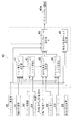
すなわち、前後駆動力配分制御部40は、図2に示すように、トランスミッション出力トルク演算部41、トルク感応トルク設定部42、差回転感応トルク設定部43、ヨーレートフィードバックトルク設定部44、制動力制御時トルク設定部45、トランスファクラッチトルク設定部46から構成されている。
【0033】
トランスミッション出力トルク演算部41は、エンジン回転数Ne、エンジン出力トルクTe、タービン回転数Nt、ギヤ比iが入力され、以下(1)式によりトランスミッション出力トルクToを演算し、このトランスミッション出力トルクToをトルク感応トルク設定部42と差回転感応トルク設定部43に出力する。
To=Te・t・i …(1)
ここで、tはトルクコンバータのトルク比であり、予め設定されている、トルクコンバータの回転速度比e(=Nt/Ne)とトルクコンバータのトルク比tとのマップを参照することにより求められる。
【0034】
トルク感応トルク設定部42は、各車輪速度ωfl,ωfr,ωrl,ωrr、ハンドル角θH、ギヤ比i、路面μ推定値μe、トラクション制御作動中か否かのON−OFF信号、制動力制御のアンダーステア傾向抑止中、オーバーステア傾向抑止中、或いは非作動中の信号及びトランスミッション出力トルクToが入力され、トルク感応トルクTtを演算してトランスファクラッチトルク設定部46に出力する。
【0035】
具体的には、まず、トルク感応トルク設定部42では、ギヤ比i毎、トラクション制御作動時、制動力制御の作動時(アンダーステア傾向抑止中、オーバーステア傾向抑止中)のそれぞれの場合毎における、予め設定しておいた後輪の駆動力配分率Aiを選択し、この後輪駆動力配分率Aiとトランスミッション出力トルクToとからトルク感応トルクTtを演算する。
Tt=Ai・To …(2)
【0036】
そして、このトルク感応トルクTtを、操舵による引きづりトルクの影響を少なくするため、操舵角δf(=θH/n:nはステアリングギヤ比)に応じたトルクの減少補正と、車速V(例えば車輪速度ωfl,ωfr,ωrl,ωrrの平均)に応じた補正を行う。
Tt=f(δf)・g(V)・Tt …(3)
【0037】
更に、(3)式で補正したトルク感応トルクTtを、予め設定しておいた路面μ毎の下限値より下回らないように制限し設定して、トランスファクラッチトルク設定部46に出力する。このように、トルク感応トルク設定部42は、トルク感応トルク設定手段として設けられている。
【0038】
差回転感応トルク設定部43は、各車輪速度ωfl,ωfr,ωrl,ωrr、ハンドル角θH、及びトランスミッション出力トルクToが入力され、以下(4)式にて差回転感応トルクTsを演算し、トランスファクラッチトルク設定部46に出力する。すなわち、差回転感応トルク設定部43は、差回転感応トルク設定手段として設けられている。
Ts=KT0・(ΔN−ΔN0) …(4)
ここで、ΔNは、前軸の実際の回転速(実回転速)ωf(=(ωfl+ωfr)/2)と後軸の実際の回転速(実回転速)ωr(=(ωrl+ωrr)/2)との差(実差回転)、すなわち、ΔN=ωr−ωfである。
【0039】
また、ΔN0は、ステアリングの操舵角δfと車速Vにより必然的に発生する差回転(基本差回転)で、例えば、車両運動モデルを用いて以下のように演算する。
車両重心点の旋回半径ρcg=(1+A・V2)・(L/(θH/n))…(5)
車両重心点のすべり角βcg=((1−(m/(2・L))・(Lf/(Lr・Kr))・V2)/(1+A・V2))・(Lr/L)・(θH/n) …(6)
ここで、Aはスタビリティファクタ、mは車両質量、Lはホイールベース、Lfは前軸−重心間距離、Lrは後軸−重心間距離である。
(5)、(6)式より、
前軸の旋回半径ρf=ρcg+Lf・(sin (βcg)) …(7)
後軸の旋回半径ρr=ρcg−Lr・(sin (βcg)) …(8)
従って、
前軸の基準回転速ωf0=V・(ρf/ρcg) …(9)
後軸の基準回転速ωr0=V・(ρr/ρcg) …(10)
以上から、基本差回転ΔN0、すなわち、ΔN0=ωr0−ωf0が演算される。このため、(ΔN−ΔN0)は、実際に生じているスリップ量を示している。
【0040】
また、KT0は、トランスミッション出力トルクToによって予め設定した比例係数であり、トランスミッション出力トルクToが大きいほど大きい値に設定され、差回転を減少させるようになっている。
【0041】
ヨーレートフィードバックトルク設定部44は、各車輪速度ωfl,ωfr,ωrl,ωrr、ハンドル角θH、ヨーレートγが入力され、車速V及び操舵角δfによって定めた車体の目標ヨーレートγ' と実際のヨーレートを比較し、その値が一致するように増減すべきヨーレートフィードバックトルクTyを演算し、このヨーレートフィードバックトルクTyをトランスファクラッチトルク設定部46に出力する。すなわち、このヨーレートフィードバックトルク設定部44は、ヨーレートフィードバックトルク設定手段として設けられている。
【0042】
具体的には、目標ヨーレートγ' は、以下の(11)式で演算する。
γ' =(1/(1+T・s))・(1/(1+A・V2))・(V/L)・δf …(11)
ここで、Tは時定数、sはラプラス演算子である。
【0043】
そして、この目標ヨーレートγ' と実際のヨーレートγとからヨーレート偏差Δγ(=γ−γ' )を演算し、このヨーレート偏差Δγが0になるようにヨーレートフィードバックトルクTyを設定する。
【0044】
制動力制御時トルク設定部45は、各車輪速度ωfl,ωfr,ωrl,ωrr、路面μ推定値μe、制動力制御のアンダーステア傾向抑止中、オーバーステア傾向抑止中、或いは非作動中の各信号が入力され、制動力制御部31がアンダーステア傾向抑止中、或いはオーバーステア傾向抑止中における、トランスファクラッチトルクTtrの補正量Ttryhを演算し、この補正量Ttryhをトランスファクラッチトルク設定部46に出力する。
【0045】
補正量Ttryhは、例えば、次のように演算する。
まず、制動力制御部31がアンダーステア傾向抑止中の場合は、予め定めておいた微少トルクΔTに対して、定数Kusを乗算することで補正量Ttryhを演算する。
Ttryh=Kus・ΔT …(12)
ここで、定数Kusは、車速Vと路面μ推定値μeにより可変に設定するもので、車速Vが高いほど大きく、路面μ推定値μeが小さいほど小さくする。すなわち、車速Vが高いほど大きく補正して速やかに車両挙動を安定させる。また、路面μ推定値μeが小さい場合は、車両特性が急に変化することを防止するため、補正量Ttryhの増減を微少なものとする。そして、アンダーステア傾向が強いほど、前後50:50の4輪駆動の方向に、すなわち、トランスファクラッチトルクTtrを増加する方向に補正する。
【0046】
一方、制動力制御部31がオーバーステア傾向抑止中の場合は、予め定めておいた微少トルクΔTに対して、定数Kosを乗算することで補正量Ttryhを演算する。
Ttryh=Kos・ΔT …(13)
ここで、定数Kosは、定数Kusと同様に、車速Vと路面μ推定値μeにより可変に設定するもので、車速Vが高いほど大きく、路面μ推定値μeが小さいほど小さくする。そして、オーバーステア傾向が強いほど、前後100:0の2輪駆動の方向に、すなわち、トランスファクラッチトルクTtrを減少する方向に補正する。
【0047】
尚、本実施の形態では、FFベースの4輪駆動車であるため、トランスファクラッチトルクTtrの増減は上述のようになるが、フロントエンジン・リヤドライブ車ベース(FRベース)の4輪駆動車の場合は、トランスファクラッチトルクの締結は、上述と逆になることは云うまでもない。
【0048】
トランスファクラッチトルク設定部46は、エンジン制御部32にトラクション制御によるトルクダウン指令を出力中か否かのON−OFF信号、制動力制御のアンダーステア傾向抑止中、オーバーステア傾向抑止中、或いは非作動中の各信号、及び、トルク感応トルクTt、差回転感応トルクTs、ヨーレートフィードバックトルクTyが入力され、必要に応じて補正量Ttryhを読み込む。
【0049】
そして、これらに基づき、トランスファクラッチトルク設定部46は、トランスファクラッチトルクTtrを以下の各場合のように設定してトランスファクラッチ駆動部40aに出力する。すなわち、トランスファクラッチトルク設定部46は、作動トルク設定手段として設けられている。
【0050】
、エンジン制御部32にトラクション制御によるトルクダウン指令なし、制動力制御の非作動の場合は、トランスファクラッチトルクTtrを以下のように設定する。
Ttr=Tt+Ts+Ty …(14)
【0051】
また、エンジン制御部32にトラクション制御によるトルクダウン指令出力中、制動力制御の非作動の場合は、トランスファクラッチトルクTtrを以下のように設定する。
Ttr=Tt …(15)
【0052】
また、制動力制御の作動の場合(トラクション制御によるトルクダウン指令は出力中であっても出力されていなくても)には、トランスファクラッチトルクTtrは、制動力制御がアンダーステア傾向抑止中、或いはオーバーステア傾向抑止中によって可変して設定される補正量Ttryhを用いて以下のように設定される。
Ttr=Tt+Ttryh …(16)
【0053】
このように、たとえ制動力制御部31、トラクション制御部33が作動しても、これらの制御量と干渉する虞のあるトルク部分のみが除かれてトランスファクラッチトルクTtrが設定され動力配分制御されるので、制動力制御部31、トラクション制御部33と必要以上に干渉することなく最適な動力配分制御を継続して行い、ドライバに違和感を与えることなく優れた走行性を維持することができるようになっている。
【0054】
また、トランスファクラッチトルク設定部46は、制動力制御部31、トラクション制御部33の作動・非作動によりトランスファクラッチトルクTtrを可変する際、例えば、図3に示すように、トランスファクラッチトルクTtrの変化に時間遅れを設けて行う。
【0055】
これは、例えば、以下のように前回のトランスファクラッチトルクTtrに対する今回演算したトランスファクラッチトルクTtrの割合を次第に増加させ設定していくことにより行われる。すなわち、最終的にトランスファクラッチ駆動部40aに出力するトランスファクラッチトルクをTtrs 、前回のトランスファクラッチトルクをTtrn-1 、今回のトランスファクラッチトルクをTtrn として、
Ttrs =(1−kts)・Ttrn-1 +kts・Ttrn …(17)
ここで、定数ktsは、0<kts<1であり、操舵角δf、車速V、路面μ推定値μeにより可変に設定される。例えば、操舵角δfが大きく、車速Vが高く、路面μ推定値μeが高いほど定数ktsを大きく設定して、トランスファクラッチトルクTtrの変化速度を大きくする。このように運転状態と走行環境に応じて制動力制御部31、トラクション制御部33の作動・非作動によるトランスファクラッチトルクTtrの変化の仕方を変えることで、トランスファクラッチトルクTtrの急激な変化が防止でき、自然に最適な制御に移行することができるようになっている。
【0056】
次に、本実施の形態による前後駆動力配分制御を、図4のフローチャートで説明する。このプログラムは、所定時間毎に繰り返し実行されるもので、まず、ステップ(以下「S」と略称)101で必要なパラメータを読み込む。
【0057】
次いで、S102に進み、トランスミッション出力トルク演算部41で(1)式によりトランスミッション出力トルクToを演算し、S103に進んで、トルク感応トルク設定部42で(3)式と路面μ毎の下限値による制限を加えてトルク感応トルクTtを設定する。
【0058】
更に、S104に進み、差回転感応トルク設定部43で(4)式により差回転感応トルクTsを演算し、S105に進み、ヨーレートフィードバックトルク設定部44でヨーレートフィードバックトルクTyを設定する。
【0059】
その後、S106に進み、制動力制御部31における制動力制御のアンダーステア傾向抑止中、オーバーステア傾向抑止中、或いは非作動中の各信号を判定し、制動力制御がアンダーステア傾向抑止中又はオーバーステア傾向抑止中の作動中の場合はS107に、制動力制御が非作動中の場合はS111に進む。
【0060】
そしてまず、制動力制御が作動中でS107に進むと、アンダーステア傾向抑止中か否か判定し、アンダーステア傾向抑止中の場合はS108に進み、制動力制御時トルク設定部45にて(12)式により補正量Ttryhを演算する。その後、S109に進み、トランスファクラッチトルク設定部46でトランスファクラッチトルクTtrを(16)式、すなわち、Ttr=Tt+Ttryhで設定する。
【0061】
また、S107でアンダーステア傾向抑止中ではない、すなわち、オーバーステア傾向抑止中の場合はS110に進み、制動力制御時トルク設定部45にて(13)式により補正量Ttryhを演算する。その後、S109に進み、トランスファクラッチトルク設定部46でトランスファクラッチトルクTtrを(16)式で設定する。
【0062】
一方、S106にて制動力制御が非作動中と判定してS111に進むと、エンジン制御部32にトラクション制御によるトルクダウン指令を出力中か否か判定する。
【0063】
そして、エンジン制御部32にトラクション制御によるトルクダウン指令を出力中の場合はS112に進み、トランスファクラッチトルク設定部46でトランスファクラッチトルクTtrを(15)式、すなわち、Ttr=Ttで設定する。
【0064】
また、エンジン制御部32にトラクション制御によるトルクダウン指令を出力していない場合はS113に進み、トランスファクラッチトルク設定部46でトランスファクラッチトルクTtrを(14)式、すなわち、Ttr=Tt+Ts+Tyで設定する。
【0065】
上記S109、S112、或いはS113でトランスファクラッチトルクTtrの設定を終えると、S114に進み、トランスファクラッチトルク設定部46では、S109、S112、或いはS113を初回に通過してきた場合にのみ、(17)式で示す初回変化処理を行って最終的なトランスファクラッチトルクをTtrs を設定し、トランスファクラッチ駆動部40aに出力する。
【0066】
このように本発明の実施の形態では、たとえ制動力制御部31、トラクション制御部33が作動しても、これらの制御量と干渉する虞のあるトルク部分のみが除かれてトランスファクラッチトルクTtrが設定され動力配分制御されるので、制動力制御部31、トラクション制御部33と必要以上に干渉することなく最適な動力配分制御を継続して行い、ドライバに違和感を与えることなく優れた走行性を維持することができる。
【0067】
すなわち、4輪駆動本来の最適な動力配分を維持しつつ、過度の車輪スリップは、制動力制御やトラクション制御により防止できるので、常に理想的な走行性能を発揮することができる。また、前後駆動力配分制御のみを変更することで、制動制御やトラクション制御を変更することなく簡単に制御の向上が達成できる。更に、制動力制御、トラクション制御の作動、非作動でトランスファクラッチトルクTtrを可変する際、所定に緩やかに変化するようにしたので、前後動力配分の変化に伴う車両特性の変化も緩やかで、自然で扱いやすい制御となっている。また、制御対象となる4輪駆動の形式は、本実施形態のFFベースの差動機構無しのものに限ることなく、FRベースの差動機構無しのもの、或いは、FF(FR)ベースの差動機構付きのもの等、他の形式のものであっても良く、汎用性が極めて広い。そして、このような他の4輪駆動形式に適用する場合も、制御特性のみを変更することで容易に適用できる。また、本実施の形態では、車両挙動制御を制動力制御とトラクション制御の2種類を例に説明したが、どちらかのみでも適用でき、また、後輪操舵制御や左右駆動力配分制御等の他の車両挙動制御であっても略同様に対応できる。
【0068】
【発明の効果】
以上、説明したように本発明によれば、車両挙動制御装置が作動して車両挙動制御が行われる場合であっても、この車両挙動制御と必要以上に干渉することなく最適な動力配分制御を継続して行い、ドライバに違和感を与えることなく優れた走行性を維持することが可能になる。
【図面の簡単な説明】
【図1】車両全体の概略構成を示す説明図
【図2】前後駆動力配分制御部の機能ブロック図
【図3】トラクション制御が作動した際のトランスファクラッチトルクの変化の一例を示す説明図
【図4】前後駆動力配分制御のフローチャート
【符号の説明】
2a トランスミッション出力軸
3 トランスファー
4 リヤドライブ軸
10 フロントドライブ軸
15 トランスファクラッチ(トルク伝達容量可変型クラッチ手段)
21fl,21fr,21rl,21rr 車輪速度センサ
25 路面μ推定装置
31 制動力制御部(車両挙動制御手段)
33 トラクション制御部(車両挙動制御手段)
40 前後駆動力配分制御部(動力配分制御手段)
41 トランスミッション出力トルク演算部
42 トルク感応トルク設定部(トルク感応トルク設定手段)
43 差回転感応トルク設定部(差回転感応トルク設定手段)
44 ヨーレートフィードバックトルク設定部(ヨーレートフィードバックトルク設定手段)
45 制動力制御時トルク設定部
46 トランスファクラッチトルク設定部(作動トルク設定手段)[0001]
BACKGROUND OF THE INVENTION
The present invention relates to a power distribution control device for a four-wheel drive vehicle that performs appropriate control when a traction control device, a braking force control device, or the like that controls vehicle behavior is operated.
[0002]
[Prior art]
In recent years, in automobiles, the traction control device for suppressing the idling of the drive wheels and ensuring the acceleration performance and steering stability at the time of starting, and the stability of the vehicle behavior, or the vehicle behavior at the time of turning the vehicle has been selected. A vehicle behavior control device such as a braking force control device that applies a braking force to wheels and appropriately controls the vehicle is mounted.
[0003]
When such a vehicle behavior control device is mounted on a four-wheel drive vehicle, the control by the vehicle behavior control device interferes with the control by the power distribution control device for the four-wheel drive vehicle, which may be undesirable for the vehicle. For this reason, for example, Japanese Patent Laid-Open No. 61-37541 discloses a four-wheel drive vehicle that forcibly switches to two-wheel drive at the time of slip control operation.
[0004]
[Problems to be solved by the invention]
However, in the above-described prior art, the four-wheel drive is switched to the two-wheel drive at the same time as the slip control operation, and there is a possibility that the traveling performance is remarkably deteriorated. In addition, there is a problem that the driver feels a sense of incongruity due to a sudden change in vehicle characteristics caused by switching from four-wheel drive to two-wheel drive.
[0005]
The present invention has been made in view of the above circumstances, and even when the vehicle behavior control device is activated and the vehicle behavior control is performed, the optimum power distribution control is performed without excessively interfering with the vehicle behavior control. The object of the present invention is to provide a power distribution control device for a four-wheel drive vehicle capable of maintaining excellent running performance without causing the driver to feel uncomfortable.
[0006]
[Means for Solving the Problems]
In order to achieve the above object, a power distribution control device for a four-wheel drive vehicle according to the present invention as set forth in claim 1 includes vehicle behavior control means for controlling the behavior of the vehicle to a predetermined value, and an operation set by the power distribution control means. In the power distribution control device for a four-wheel drive vehicle that operates the torque transmission capacity variable type clutch means with torque and distributes the power in the front and rear, the power distribution control means has a torque corresponding to the input torque from the drive source to be distributed in the front and rear. Torque sensitive torque setting means for calculating the sensitive torque, differential rotation sensitive torque setting means for calculating the differential rotation sensitive torque according to the rotational difference between the front and rear shafts, and at least the operation from the torque sensitive torque and the differential rotation sensitive torque. Actuating torque setting means for calculating torque and calculating the operating torque excluding the differential rotation sensitive torque when the vehicle behavior control means is operated Characterized by comprising a.
[0007]
According to a second aspect of the present invention, there is provided a power distribution control device for a four-wheel drive vehicle, comprising vehicle behavior control means for controlling the behavior of the vehicle to a predetermined value, and transmitting torque with an operating torque set by the power distribution control means. In a power distribution control device for a four-wheel drive vehicle that operates a capacity variable clutch means to distribute power in the front and rear, the power distribution control means calculates a torque sensitive torque according to an input torque from a drive source that is distributed in the front and rear. Torque sensitive torque setting means, differential rotation sensitive torque setting means for calculating differential rotation sensitive torque according to the rotational difference between the front and rear axes, yaw rate feedback torque setting means for calculating yaw rate feedback torque based on the yawing state of the vehicle, At least the torque sensitive torque, the differential rotation sensitive torque, and the yaw rate feedback torque And an operating torque setting means for calculating the operating torque excluding the differential rotation sensitive torque and the yaw rate feedback torque when the vehicle behavior control means is operated. .
[0008]
Furthermore, a power distribution control device for a four-wheel drive vehicle according to the present invention described in
[0009]
According to a fourth aspect of the present invention, there is provided a power distribution control device for a four-wheel drive vehicle according to the present invention, wherein the correction amount is at least one of a vehicle speed and a road surface friction coefficient. It is characterized by being variably set according to the above.
[0010]
Further, a power distribution control device for a four-wheel drive vehicle according to the present invention described in
[0011]
That is, in the power distribution control device for a four-wheel drive vehicle according to claim 1, the power distribution control means calculates a torque sensitive torque according to the input torque from the drive source distributed back and forth by the torque sensitive torque setting means, The differential rotation sensitive torque setting means calculates a differential rotation sensitive torque corresponding to the rotational difference between the front and rear axes, and the operating torque setting means calculates an operating torque from at least the torque sensitive torque and the differential rotation sensitive torque. Then, the torque transmission capacity variable clutch means is operated with this operating torque to distribute power before and after. Here, when the vehicle behavior control means operates to control the behavior of the vehicle to a predetermined value, the operating torque setting means of the power distribution control means calculates the operating torque excluding the differential rotation sensitive torque, and the torque is calculated using this operating torque. The variable transmission capacity clutch means is controlled. For this reason, even when the vehicle behavior control means is activated and the vehicle behavior control is performed, the optimal power distribution control is continuously performed without interfering with the vehicle behavior control, and the driver feels uncomfortable. Excellent running performance is maintained.
[0012]
Further, in the power distribution control device for a four-wheel drive vehicle according to
[0013]
Furthermore, the power distribution control device for a four-wheel drive vehicle according to
[0014]
The power distribution control device for a four-wheel drive vehicle according to claim 4 is the power distribution control device for a four-wheel drive vehicle according to
[0015]
Furthermore, the power distribution control device for a four-wheel drive vehicle according to
[0016]
DETAILED DESCRIPTION OF THE INVENTION
Hereinafter, embodiments of the present invention will be described with reference to the drawings.
1 to 4 show an embodiment of the present invention, FIG. 1 is an explanatory diagram showing a schematic configuration of the entire vehicle, FIG. 2 is a functional block diagram of a front / rear driving force distribution control unit, and FIG. FIG. 4 is a flowchart of front / rear driving force distribution control.
[0017]
In FIG. 1, reference numeral 1 denotes an engine disposed in the front part of the vehicle, and the driving force of the engine 1 is transmitted from an automatic transmission device (including a torque converter and the like) 2 behind the engine 1 through a transmission output shaft 2a. It is transmitted to the
[0018]
Further, the driving force transmitted to the
[0019]
The driving force input to the rear wheel final reduction gear 7 is transmitted to the left rear wheel 14rl via the rear wheel left drive shaft 13rl and to the right rear wheel 14rr via the rear wheel right drive shaft 13rr. The driving force input to the front wheel final reduction gear 11 is transmitted to the left front wheel 14fl via the front wheel left drive shaft 13fl and to the right front wheel 14fr via the front wheel right drive shaft 13fr.
[0020]
The
[0021]
Further, the pressing force of the
[0022]
On the other hand, reference numeral 31a represents a brake drive unit of the vehicle, and a master cylinder (not shown) connected to a brake pedal operated by a driver is connected to the brake drive unit 31a. When the driver operates the brake pedal, the wheel cylinders of the four wheels 14fl, 14fr, 14rl, 14rr (the left front wheel cylinder 17fl, the right front wheel wheel cylinder 17fr, the left rear wheel wheel cylinder) are driven by the master cylinder through the brake drive unit 31a. 17 rl, the right rear wheel wheel cylinder 17 rr) is introduced with a brake pressure, which brakes the four wheels.
[0023]
The brake drive unit 31a is a hydraulic unit including a pressurizing source, a pressure reducing valve, a pressure increasing valve, and the like, and in addition to the brake operation by the driver described above, A brake pressure can be independently introduced into each of the wheel cylinders 17fl, 17fr, 17rl, and 17rr.
[0024]
Further, an output signal from a
[0025]
The braking
[0026]
The vehicle is provided with sensors and the like for detecting parameters necessary for control by the
[0027]
Further, the vehicle is provided with a road surface μ
[0028]
The braking
[0029]
The
[0030]
The front / rear driving force
[0031]
Based on these input signals, torque sensitive torque Tt, differential rotation sensitive torque Ts and yaw rate feedback torque Ty are calculated, and transfer clutch torque Ttr is calculated from these torques.
[0032]
That is, as shown in FIG. 2, the front / rear driving force
[0033]
The transmission output
To = Te · t · i (1)
Here, t is a torque ratio of the torque converter, and is obtained by referring to a map of a preset rotation speed ratio e (= Nt / Ne) of the torque converter and a torque ratio t of the torque converter.
[0034]
The torque sensitive
[0035]
Specifically, first, in the torque sensitive
Tt = Ai · To (2)
[0036]
In order to reduce the influence of the drag torque due to the steering, the torque sensitive torque Tt is corrected to reduce the torque according to the steering angle δf (= θH / n: n is a steering gear ratio) and the vehicle speed V (for example, the wheel). Correction according to the average of the speeds ωfl, ωfr, ωrl, and ωrr.
Tt = f (δf) · g (V) · Tt (3)
[0037]
Further, the torque sensitive torque Tt corrected by the equation (3) is set so as not to be lower than a preset lower limit value for each road surface μ, and is output to the transfer clutch
[0038]
The differential rotation sensitive
Ts = KT0 · (ΔN−ΔN0) (4)
Here, ΔN is the actual rotational speed (actual rotational speed) ωf (= (ωfl + ωfr) / 2) of the front shaft and the actual rotational speed (actual rotational speed) ωr (= (ωrl + ωrr) / 2) of the rear shaft. Difference (actual difference rotation), that is, ΔN = ωr−ωf.
[0039]
ΔN0 is a differential rotation (basic differential rotation) that inevitably occurs due to the steering angle δf of the steering and the vehicle speed V, and is calculated as follows using, for example, a vehicle motion model.
Turning radius ρcg = (1 + A ・ V) 2 ) · (L / (θH / n)) (5)
Slip angle βcg = ((1− (m / (2 · L)) · (Lf / (Lr · Kr)) · V 2 ) / (1 + A · V 2 )) · (Lr / L) · (θH / n) (6)
Here, A is the stability factor, m is the vehicle mass, L is the wheel base, Lf is the distance between the front axis and the center of gravity, and Lr is the distance between the rear axis and the center of gravity.
From equations (5) and (6)
The turning radius of the front shaft ρf = ρcg + Lf · (sin (βcg)) (7)
Rear axis turning radius ρr = ρcg−Lr · (sin (βcg)) (8)
Therefore,
Front shaft reference rotational speed ωf0 = V · (ρf / ρcg) (9)
Rear shaft reference rotational speed ωr0 = V · (ρr / ρcg) (10)
From the above, the basic differential rotation ΔN0, that is, ΔN0 = ωr0−ωf0 is calculated. For this reason, (ΔN−ΔN0) indicates the slip amount actually generated.
[0040]
Further, KT0 is a proportional coefficient set in advance by the transmission output torque To, and is set to a larger value as the transmission output torque To is larger, so that the differential rotation is reduced.
[0041]
The yaw rate feedback
[0042]
Specifically, the target yaw rate γ ′ is calculated by the following equation (11).
γ ′ = (1 / (1 + T · s)) · (1 / (1 + A · V 2 )) · (V / L) · δf (11)
Here, T is a time constant, and s is a Laplace operator.
[0043]
Then, a yaw rate deviation Δγ (= γ−γ ′) is calculated from the target yaw rate γ ′ and the actual yaw rate γ, and the yaw rate feedback torque Ty is set so that the yaw rate deviation Δγ becomes zero.
[0044]
The braking force control
[0045]
The correction amount Ttryh is calculated as follows, for example.
First, when the braking
Ttryh = Kus · ΔT (12)
Here, the constant Kus is variably set according to the vehicle speed V and the road surface μ estimated value μe, and increases as the vehicle speed V increases and decreases as the road surface μ estimated value μe decreases. That is, as the vehicle speed V is higher, the vehicle behavior is quickly stabilized by making a larger correction. Further, when the road surface μ estimated value μe is small, the correction amount Ttryh is increased or decreased to prevent the vehicle characteristics from changing suddenly. Then, the stronger the understeer tendency, the more in the direction of front and rear 50:50 four-wheel drive, that is, in the direction of increasing the transfer clutch torque Ttr.
[0046]
On the other hand, when the braking
Ttryh = Kos · ΔT (13)
Here, like the constant Kus, the constant Kos is variably set by the vehicle speed V and the road surface μ estimated value μe. The constant Kos increases as the vehicle speed V increases and decreases as the road surface μ estimated value μe decreases. Then, the stronger the oversteer tendency, the more the correction is made in the direction of two-wheel drive of 100: 0 front and rear, that is, the direction of decreasing the transfer clutch torque Ttr.
[0047]
In the present embodiment, since it is an FF-based four-wheel drive vehicle, the increase / decrease in the transfer clutch torque Ttr is as described above, but the front engine / rear drive vehicle base (FR base) four-wheel drive vehicle In this case, it goes without saying that the engagement of the transfer clutch torque is opposite to that described above.
[0048]
The transfer clutch
[0049]
Based on these, the transfer clutch
[0050]
When there is no torque down command by the traction control to the
Ttr = Tt + Ts + Ty (14)
[0051]
When the torque control command is being output to the
Ttr = Tt (15)
[0052]
In addition, in the case of braking force control operation (whether the torque reduction command by traction control is being output or not), the transfer clutch torque Ttr is determined when the braking force control is understeer tendency suppression or overshooting. Using the correction amount Ttryh that is variably set according to the suppression of the steering tendency, the following is set.
Ttr = Tt + Ttryh (16)
[0053]
In this way, even if the braking
[0054]
Further, when the transfer clutch
[0055]
This is performed, for example, by gradually increasing and setting the ratio of the transfer clutch torque Ttr calculated this time to the previous transfer clutch torque Ttr as follows. That is, the transfer clutch torque finally output to the transfer
Ttrs = (1−kts) · Ttrn−1 + kts · Ttrn (17)
Here, the constant kts is 0 <kts <1, and is variably set according to the steering angle δf, the vehicle speed V, and the road surface μ estimated value μe. For example, the constant kts is set larger as the steering angle δf is larger, the vehicle speed V is higher, and the road surface μ estimated value μe is higher, so that the changing speed of the transfer clutch torque Ttr is increased. In this way, a sudden change in the transfer clutch torque Ttr is prevented by changing the manner in which the transfer clutch torque Ttr changes due to the operation / non-operation of the braking
[0056]
Next, front and rear driving force distribution control according to the present embodiment will be described with reference to the flowchart of FIG. This program is repeatedly executed at predetermined time intervals. First, in step (hereinafter abbreviated as “S”) 101, necessary parameters are read.
[0057]
Next, the process proceeds to S102, where the transmission output
[0058]
Further, in S104, the differential rotation sensitive
[0059]
Thereafter, the process proceeds to S106, in which each signal indicating whether the braking
[0060]
First, when the braking force control is operating and the process proceeds to S107, it is determined whether or not the understeer tendency is being suppressed. If the understeer tendency is being suppressed, the process proceeds to S108, and the braking force control
[0061]
If the understeer tendency is not being suppressed in S107, that is, if the oversteer tendency is being suppressed, the process proceeds to S110, and the braking force control
[0062]
On the other hand, when it is determined in S106 that the braking force control is not in operation and the process proceeds to S111, it is determined whether or not a torque down command by traction control is being output to the
[0063]
If a torque down command by traction control is being output to the
[0064]
When the torque reduction command by the traction control is not output to the
[0065]
When the setting of the transfer clutch torque Ttr is completed in S109, S112, or S113, the process proceeds to S114, and the transfer clutch
[0066]
As described above, in the embodiment of the present invention, even if the braking
[0067]
That is, excessive wheel slip can be prevented by braking force control or traction control while maintaining the optimal power distribution inherent in the four-wheel drive, and therefore, ideal driving performance can always be exhibited. Further, by changing only the front / rear driving force distribution control, the control can be easily improved without changing the braking control or the traction control. In addition, when changing the transfer clutch torque Ttr with or without braking force control or traction control, it changes gently to a predetermined level. The control is easy to handle. Also, the four-wheel drive type to be controlled is not limited to the one without the FF-based differential mechanism of the present embodiment, but the difference without the FR-based differential mechanism or the difference between the FF (FR) bases. Other types such as those with a moving mechanism may be used, and the versatility is extremely wide. And also when applying to such other 4 wheel drive types, it can apply easily by changing only a control characteristic. In the present embodiment, the vehicle behavior control has been described using two types of braking force control and traction control as examples. However, only one of them can be applied, and other functions such as rear wheel steering control and left / right driving force distribution control can be applied. This vehicle behavior control can be handled in substantially the same manner.
[0068]
【The invention's effect】
As described above, according to the present invention, even when the vehicle behavior control device is operated and the vehicle behavior control is performed, the optimum power distribution control is performed without interfering with the vehicle behavior control more than necessary. This is done continuously, and it becomes possible to maintain excellent running performance without giving the driver a sense of incongruity.
[Brief description of the drawings]
FIG. 1 is an explanatory diagram showing a schematic configuration of an entire vehicle
FIG. 2 is a functional block diagram of a front / rear driving force distribution control unit.
FIG. 3 is an explanatory diagram showing an example of a change in transfer clutch torque when traction control is activated.
FIG. 4 is a flowchart of front / rear driving force distribution control.
[Explanation of symbols]
2a Transmission output shaft
3 Transfer
4 Rear drive shaft
10 Front drive shaft
15 Transfer clutch (torque transmission capacity variable type clutch means)
21fl, 21fr, 21rl, 21rr Wheel speed sensor
25 Road surface μ estimation device
31 Braking force control unit (vehicle behavior control means)
33 Traction control unit (vehicle behavior control means)
40 Front / rear driving force distribution control unit (power distribution control means)
41 Transmission output torque calculator
42 Torque sensitive torque setting section (torque sensitive torque setting means)
43 Differential rotation sensitive torque setting section (Differential rotation sensitive torque setting means)
44 Yaw rate feedback torque setting unit (yaw rate feedback torque setting means)
45 Torque setting section for braking force control
46 Transfer clutch torque setting section (operation torque setting means)
Claims (5)
上記動力配分制御手段は、
前後に配分する駆動源からの入力トルクに応じたトルク感応トルクを演算するトルク感応トルク設定手段と、
前後軸の回転差に応じた差回転感応トルクを演算する差回転感応トルク設定手段と、
少なくとも上記トルク感応トルクと上記差回転感応トルクとから上記作動トルクを演算し、上記車両挙動制御手段が作動した場合には上記差回転感応トルクを除いて上記作動トルクを演算する作動トルク設定手段と、
を備えたことを特徴とする4輪駆動車の動力配分制御装置。Power distribution for a four-wheel drive vehicle that includes vehicle behavior control means for controlling the behavior of the vehicle to a predetermined level and that operates the torque transmission capacity variable type clutch means with the operating torque set by the power distribution control means to distribute power before and after. In the control device,
The power distribution control means includes
A torque sensitive torque setting means for calculating a torque sensitive torque according to an input torque from a drive source distributed in the front-rear direction;
Differential rotation sensitive torque setting means for calculating a differential rotation sensitive torque according to the rotational difference between the front and rear axes;
An operating torque setting means for calculating the operating torque from at least the torque sensitive torque and the differential rotation sensitive torque and calculating the operating torque excluding the differential rotational sensitive torque when the vehicle behavior control means is activated; ,
A power distribution control device for a four-wheel drive vehicle.
上記動力配分制御手段は、
前後に配分する駆動源からの入力トルクに応じたトルク感応トルクを演算するトルク感応トルク設定手段と、
前後軸の回転差に応じた差回転感応トルクを演算する差回転感応トルク設定手段と、
車両のヨーイング状態に基づくヨーレートフィードバックトルクを演算するヨーレートフィードバックトルク設定手段と、
少なくとも上記トルク感応トルクと上記差回転感応トルクと上記ヨーレートフィードバックトルクから上記作動トルクを演算し、上記車両挙動制御手段が作動した場合には上記差回転感応トルクと上記ヨーレートフィードバックトルクとを除いて上記作動トルクを演算する作動トルク設定手段と、
を備えたことを特徴とする4輪駆動車の動力配分制御装置。Power distribution for a four-wheel drive vehicle that includes vehicle behavior control means for controlling the behavior of the vehicle to a predetermined level and that operates the torque transmission capacity variable type clutch means with the operating torque set by the power distribution control means to distribute power before and after. In the control device,
The power distribution control means includes
A torque sensitive torque setting means for calculating a torque sensitive torque according to an input torque from a drive source distributed in the front-rear direction;
Differential rotation sensitive torque setting means for calculating a differential rotation sensitive torque according to the rotational difference between the front and rear axes;
A yaw rate feedback torque setting means for calculating a yaw rate feedback torque based on the yawing state of the vehicle;
The operating torque is calculated from at least the torque sensitive torque, the differential rotation sensitive torque, and the yaw rate feedback torque. When the vehicle behavior control means is operated, the differential rotational sensitive torque and the yaw rate feedback torque are excluded. An operating torque setting means for calculating the operating torque;
A power distribution control device for a four-wheel drive vehicle.
上記作動トルク設定手段は、上記車両挙動制御手段が作動した場合には車両のオーバーステア傾向とアンダーステア傾向とに応じた補正量を加えて上記作動トルクを演算することを特徴とする請求項1又は請求項2に記載の4輪駆動車の動力配分制御装置。The vehicle behavior control means detects the oversteer tendency and the understeer tendency of the vehicle and controls them in a predetermined manner,
The operation torque setting means, when the vehicle behavior control means is operated, calculates the operation torque by adding a correction amount according to an oversteer tendency and an understeer tendency of the vehicle. The power distribution control device for a four-wheel drive vehicle according to claim 2.
Priority Applications (4)
| Application Number | Priority Date | Filing Date | Title |
|---|---|---|---|
| JP2000329348A JP4456748B2 (en) | 2000-10-27 | 2000-10-27 | Power distribution control device for four-wheel drive vehicles |
| DE60139668T DE60139668D1 (en) | 2000-10-27 | 2001-10-26 | Driving force distribution system of a vehicle |
| EP01309114A EP1203688B1 (en) | 2000-10-27 | 2001-10-26 | Power distribution control system for a vehicle |
| US09/984,149 US6634451B2 (en) | 2000-10-27 | 2001-10-29 | Power distribution control system for a vehicle |
Applications Claiming Priority (1)
| Application Number | Priority Date | Filing Date | Title |
|---|---|---|---|
| JP2000329348A JP4456748B2 (en) | 2000-10-27 | 2000-10-27 | Power distribution control device for four-wheel drive vehicles |
Publications (2)
| Publication Number | Publication Date |
|---|---|
| JP2002127772A JP2002127772A (en) | 2002-05-08 |
| JP4456748B2 true JP4456748B2 (en) | 2010-04-28 |
Family
ID=18806030
Family Applications (1)
| Application Number | Title | Priority Date | Filing Date |
|---|---|---|---|
| JP2000329348A Expired - Fee Related JP4456748B2 (en) | 2000-10-27 | 2000-10-27 | Power distribution control device for four-wheel drive vehicles |
Country Status (4)
| Country | Link |
|---|---|
| US (1) | US6634451B2 (en) |
| EP (1) | EP1203688B1 (en) |
| JP (1) | JP4456748B2 (en) |
| DE (1) | DE60139668D1 (en) |
Families Citing this family (44)
| Publication number | Priority date | Publication date | Assignee | Title |
|---|---|---|---|---|
| JP4456748B2 (en) * | 2000-10-27 | 2010-04-28 | 富士重工業株式会社 | Power distribution control device for four-wheel drive vehicles |
| JP2003312289A (en) * | 2002-04-23 | 2003-11-06 | Toyoda Mach Works Ltd | Four-wheeled-drive vehicle |
| JP4265891B2 (en) * | 2002-08-06 | 2009-05-20 | 富士重工業株式会社 | Vehicle driving force transmission control device |
| JP4263441B2 (en) * | 2002-08-07 | 2009-05-13 | 富士重工業株式会社 | Control device for four-wheel drive vehicle |
| JP2004106649A (en) * | 2002-09-17 | 2004-04-08 | Fuji Heavy Ind Ltd | Power distribution controller of four-wheel drive vehicle |
| JP4263448B2 (en) * | 2002-09-24 | 2009-05-13 | 富士重工業株式会社 | Vehicle differential limiting control device |
| JP4386171B2 (en) | 2003-12-04 | 2009-12-16 | 三菱自動車工業株式会社 | Power transmission device for four-wheel drive vehicles |
| JP4554252B2 (en) * | 2004-03-31 | 2010-09-29 | 本田技研工業株式会社 | Control method for four-wheel drive vehicle |
| JP4500126B2 (en) * | 2004-08-02 | 2010-07-14 | 富士重工業株式会社 | Fault diagnosis device for yaw rate sensor |
| US7634342B2 (en) * | 2005-03-18 | 2009-12-15 | Honda Motor Co., Ltd. | Method for deploying a torque reduction and torque limitation command through per wheel torque control of a controllable 4-wheel-drive system |
| JP4600126B2 (en) * | 2005-04-05 | 2010-12-15 | 株式会社アドヴィックス | Vehicle attitude control device |
| EP2241470B1 (en) | 2005-06-10 | 2012-03-14 | Fuji Jukogyo Kabushiki Kaisha | Front and rear drive power distribution control device for vehicle |
| JP4823577B2 (en) * | 2005-06-10 | 2011-11-24 | 富士重工業株式会社 | Front / rear driving force distribution control device for vehicle |
| JP4684755B2 (en) * | 2005-06-10 | 2011-05-18 | 富士重工業株式会社 | Front / rear driving force distribution control device for vehicle |
| JP2006341825A (en) * | 2005-06-10 | 2006-12-21 | Fuji Heavy Ind Ltd | Driving force distribution control device of vehicle |
| US7966113B2 (en) * | 2005-08-25 | 2011-06-21 | Robert Bosch Gmbh | Vehicle stability control system |
| US7614470B2 (en) * | 2005-10-11 | 2009-11-10 | Borgwarner, Inc. | Torque proportioning control system |
| JP4969833B2 (en) * | 2005-11-08 | 2012-07-04 | 富士重工業株式会社 | Vehicle behavior control device |
| US7455142B2 (en) * | 2005-12-05 | 2008-11-25 | Honda Motor Co., Ltd. | Scaling of side-to-side torque bias to improve cornering in a programmable four wheel drive system |
| US8321110B2 (en) * | 2005-12-06 | 2012-11-27 | Honda Motor Co., Ltd. | Detection of hill grade and feed-forward distribution of 4WD torque bias to improve traction on a low MU surfaces during climbing of such hill grade |
| DE102006027834B4 (en) * | 2006-06-16 | 2014-02-13 | Engineering Center Steyr Gmbh & Co. Kg | Method for determining a torque |
| JP4980168B2 (en) * | 2007-08-01 | 2012-07-18 | 富士重工業株式会社 | Vehicle behavior control device |
| JP4955482B2 (en) * | 2007-08-07 | 2012-06-20 | 日産自動車株式会社 | Driving force distribution control device for four-wheel drive vehicles |
| JP5083526B2 (en) * | 2007-08-31 | 2012-11-28 | 三菱自動車工業株式会社 | Vehicle driving force control device |
| JP4964333B2 (en) * | 2009-12-07 | 2012-06-27 | 本田技研工業株式会社 | Control device for four-wheel drive vehicle |
| US8532890B2 (en) * | 2011-11-10 | 2013-09-10 | GM Global Technology Operations LLC | Driven wheel torque estimation systems and methods |
| JP5483770B2 (en) * | 2012-09-21 | 2014-05-07 | 富士重工業株式会社 | Control device for four-wheel drive vehicle |
| US8918263B2 (en) | 2013-03-14 | 2014-12-23 | Clark Equipment Company | Traction control for power machine |
| US9194484B2 (en) | 2013-04-11 | 2015-11-24 | GM Global Technology Operations LLC | System and method for detecting lash in a transmission and controlling an engine and/or a motor based on lash detections |
| US9080619B2 (en) | 2013-04-11 | 2015-07-14 | GM Global Technology Operations LLC | Clutch slip identification systems and methods |
| US10184295B2 (en) * | 2014-10-02 | 2019-01-22 | Caterpillar Inc. | Machine leveling assembly and method |
| US11399995B2 (en) | 2016-02-23 | 2022-08-02 | Deka Products Limited Partnership | Mobility device |
| US10908045B2 (en) | 2016-02-23 | 2021-02-02 | Deka Products Limited Partnership | Mobility device |
| US10926756B2 (en) | 2016-02-23 | 2021-02-23 | Deka Products Limited Partnership | Mobility device |
| MX2021007862A (en) | 2016-02-23 | 2022-09-22 | Deka Products Lp | Mobility device control system. |
| US9758167B1 (en) * | 2016-03-08 | 2017-09-12 | Gkn Driveline North America, Inc. | Hill detection and grade percent estimation logic for an all-wheel drive system |
| CA3210026A1 (en) | 2016-04-14 | 2017-10-19 | Deka Products Limited Partnership | User control device for a transporter |
| JP6743637B2 (en) * | 2016-10-04 | 2020-08-19 | 株式会社ジェイテクト | Control device for driving force transmission device |
| JP6412192B2 (en) | 2017-03-17 | 2018-10-24 | 株式会社Subaru | Vehicle control device |
| CN108860137B (en) * | 2017-05-16 | 2020-06-26 | 华为技术有限公司 | Control method and device for unstable vehicle and intelligent vehicle |
| USD829612S1 (en) | 2017-05-20 | 2018-10-02 | Deka Products Limited Partnership | Set of toggles |
| USD846452S1 (en) | 2017-05-20 | 2019-04-23 | Deka Products Limited Partnership | Display housing |
| US11681293B2 (en) | 2018-06-07 | 2023-06-20 | Deka Products Limited Partnership | System and method for distributed utility service execution |
| JP6814192B2 (en) * | 2018-11-26 | 2021-01-13 | 本田技研工業株式会社 | Vehicle control devices, vehicle control methods, and programs |
Family Cites Families (21)
| Publication number | Priority date | Publication date | Assignee | Title |
|---|---|---|---|---|
| DE3426747A1 (en) * | 1984-07-20 | 1986-01-30 | Alfred Teves Gmbh, 6000 Frankfurt | SLIP-CONTROLLED BRAKE SYSTEM FOR MOTOR VEHICLES WITH ALL-WHEEL DRIVE |
| JPS6259126A (en) * | 1985-09-09 | 1987-03-14 | Mazda Motor Corp | Transmission torque controller for four-wheel drive car |
| JP2534732B2 (en) * | 1987-10-05 | 1996-09-18 | 日産自動車株式会社 | Drive force distribution controller for four-wheel drive vehicle |
| JPH01114523A (en) * | 1987-10-27 | 1989-05-08 | Fuji Heavy Ind Ltd | Drive power controller for four-wheel-drive vehicle |
| US5224044A (en) * | 1988-02-05 | 1993-06-29 | Nissan Motor Company, Limited | System for controlling driving condition of automotive device associated with vehicle slip control system |
| US5041978A (en) * | 1989-01-17 | 1991-08-20 | Mazda Motor Corporation | Power train control apparatus |
| JPH02290737A (en) * | 1989-04-28 | 1990-11-30 | Fuji Heavy Ind Ltd | Driving power distribution control device of four-wheel drive vehicle |
| JP2760865B2 (en) * | 1989-10-09 | 1998-06-04 | 日産自動車株式会社 | Traction control device for four-wheel drive vehicles |
| US5270930A (en) * | 1990-11-30 | 1993-12-14 | Mitsubishi Jidosha Kogyo Kabushiki Kaisha | Four wheel driving vehicle of a front/rear wheel differential operation limiting type |
| JPH06137541A (en) | 1992-10-23 | 1994-05-17 | Mitsubishi Heavy Ind Ltd | Slag discharger for burning apparatus |
| JP3033416B2 (en) * | 1993-12-28 | 2000-04-17 | 日産自動車株式会社 | Driving force distribution control device between front and rear wheels of vehicle |
| JP3268124B2 (en) * | 1994-06-27 | 2002-03-25 | 富士重工業株式会社 | Vehicle torque distribution control device |
| JP3207328B2 (en) * | 1994-12-16 | 2001-09-10 | 三菱電機株式会社 | Shaft torque detector for vehicle control |
| US5671144A (en) * | 1995-05-01 | 1997-09-23 | Zexel Torsen Inc. | Combined power limiting and power distributing traction control system for improving vehicle performance in turns |
| DE19706720A1 (en) * | 1996-04-06 | 1997-10-09 | Volkswagen Ag | Controlling coupling between front and rear axles of motor vehicle with four wheel drive |
| JPH1159216A (en) * | 1997-08-26 | 1999-03-02 | Fuji Heavy Ind Ltd | Power distributing control device for four-wheel drive vehicle |
| DE69935090T2 (en) * | 1998-06-09 | 2007-11-15 | Fuji Jukogyo K.K. | Torque distribution control system for a four-wheel drive vehicle |
| JP2002046509A (en) * | 2000-08-03 | 2002-02-12 | Fuji Heavy Ind Ltd | Movement control device for vehicle |
| JP4456748B2 (en) * | 2000-10-27 | 2010-04-28 | 富士重工業株式会社 | Power distribution control device for four-wheel drive vehicles |
| JP4638065B2 (en) * | 2001-02-08 | 2011-02-23 | 富士重工業株式会社 | Control device for four-wheel drive vehicle |
| JP3857568B2 (en) * | 2001-10-31 | 2006-12-13 | 株式会社ジェイテクト | Driving force distribution control device for four-wheel drive vehicle |
-
2000
- 2000-10-27 JP JP2000329348A patent/JP4456748B2/en not_active Expired - Fee Related
-
2001
- 2001-10-26 EP EP01309114A patent/EP1203688B1/en not_active Expired - Lifetime
- 2001-10-26 DE DE60139668T patent/DE60139668D1/en not_active Expired - Lifetime
- 2001-10-29 US US09/984,149 patent/US6634451B2/en not_active Expired - Lifetime
Also Published As
| Publication number | Publication date |
|---|---|
| JP2002127772A (en) | 2002-05-08 |
| EP1203688A3 (en) | 2005-10-05 |
| US20020055416A1 (en) | 2002-05-09 |
| DE60139668D1 (en) | 2009-10-08 |
| EP1203688A2 (en) | 2002-05-08 |
| US6634451B2 (en) | 2003-10-21 |
| EP1203688B1 (en) | 2009-08-26 |
Similar Documents
| Publication | Publication Date | Title |
|---|---|---|
| JP4456748B2 (en) | Power distribution control device for four-wheel drive vehicles | |
| JP4638065B2 (en) | Control device for four-wheel drive vehicle | |
| JP3937524B2 (en) | Vehicle braking / driving force control device | |
| JP3589202B2 (en) | Driving force control device for four-wheel drive vehicle | |
| JPH1159216A (en) | Power distributing control device for four-wheel drive vehicle | |
| US7784577B2 (en) | Vehicle tack-in prevention control device | |
| EP0844129B1 (en) | Yaw moment control system in vehicle | |
| JP3272617B2 (en) | Vehicle yaw moment control device | |
| JP2004106649A (en) | Power distribution controller of four-wheel drive vehicle | |
| EP2055599B1 (en) | Vehicle behavior control apparatus | |
| US20080234911A1 (en) | Vehicle driving force control device | |
| JP4215861B2 (en) | Power distribution control device for four-wheel drive vehicles | |
| JP3840061B2 (en) | Four-wheel drive vehicle | |
| JP4114065B2 (en) | Four-wheel drive vehicle behavior control device | |
| JP5663368B2 (en) | Vehicle driving support control device | |
| JP5256130B2 (en) | Tire force control device for four-wheel drive vehicles | |
| JP3997923B2 (en) | Regenerative braking control device for vehicle | |
| JP2004017721A (en) | Controller for four-wheel-drive vehicle | |
| JP2004231004A (en) | Wheel state estimating device for vehicle | |
| JP3612194B2 (en) | Road surface friction coefficient detector | |
| JP5125669B2 (en) | Vehicle speed estimation device for four-wheel drive vehicles | |
| JP4661450B2 (en) | Vehicle drive torque control device | |
| JP4055225B2 (en) | Vehicle braking / driving force control device | |
| JPH10138783A (en) | Yaw moment control device of vehicle | |
| JPH04146819A (en) | Drive force controller |
Legal Events
| Date | Code | Title | Description |
|---|---|---|---|
| A621 | Written request for application examination |
Free format text: JAPANESE INTERMEDIATE CODE: A621 Effective date: 20070926 |
|
| A977 | Report on retrieval |
Free format text: JAPANESE INTERMEDIATE CODE: A971007 Effective date: 20090626 |
|
| A131 | Notification of reasons for refusal |
Free format text: JAPANESE INTERMEDIATE CODE: A131 Effective date: 20090804 |
|
| A521 | Written amendment |
Free format text: JAPANESE INTERMEDIATE CODE: A523 Effective date: 20090917 |
|
| TRDD | Decision of grant or rejection written | ||
| A01 | Written decision to grant a patent or to grant a registration (utility model) |
Free format text: JAPANESE INTERMEDIATE CODE: A01 Effective date: 20100202 |
|
| A01 | Written decision to grant a patent or to grant a registration (utility model) |
Free format text: JAPANESE INTERMEDIATE CODE: A01 |
|
| A61 | First payment of annual fees (during grant procedure) |
Free format text: JAPANESE INTERMEDIATE CODE: A61 Effective date: 20100208 |
|
| FPAY | Renewal fee payment (event date is renewal date of database) |
Free format text: PAYMENT UNTIL: 20130212 Year of fee payment: 3 |
|
| R150 | Certificate of patent or registration of utility model |
Ref document number: 4456748 Country of ref document: JP Free format text: JAPANESE INTERMEDIATE CODE: R150 Free format text: JAPANESE INTERMEDIATE CODE: R150 |
|
| FPAY | Renewal fee payment (event date is renewal date of database) |
Free format text: PAYMENT UNTIL: 20140212 Year of fee payment: 4 |
|
| R250 | Receipt of annual fees |
Free format text: JAPANESE INTERMEDIATE CODE: R250 |
|
| R250 | Receipt of annual fees |
Free format text: JAPANESE INTERMEDIATE CODE: R250 |
|
| S531 | Written request for registration of change of domicile |
Free format text: JAPANESE INTERMEDIATE CODE: R313531 |
|
| R350 | Written notification of registration of transfer |
Free format text: JAPANESE INTERMEDIATE CODE: R350 |
|
| R250 | Receipt of annual fees |
Free format text: JAPANESE INTERMEDIATE CODE: R250 |
|
| R250 | Receipt of annual fees |
Free format text: JAPANESE INTERMEDIATE CODE: R250 |
|
| R250 | Receipt of annual fees |
Free format text: JAPANESE INTERMEDIATE CODE: R250 |
|
| S533 | Written request for registration of change of name |
Free format text: JAPANESE INTERMEDIATE CODE: R313533 |
|
| R350 | Written notification of registration of transfer |
Free format text: JAPANESE INTERMEDIATE CODE: R350 |
|
| R250 | Receipt of annual fees |
Free format text: JAPANESE INTERMEDIATE CODE: R250 |
|
| R250 | Receipt of annual fees |
Free format text: JAPANESE INTERMEDIATE CODE: R250 |
|
| LAPS | Cancellation because of no payment of annual fees |