JP3997923B2 - Regenerative braking control device for vehicle - Google Patents
Regenerative braking control device for vehicle Download PDFInfo
- Publication number
- JP3997923B2 JP3997923B2 JP2003030699A JP2003030699A JP3997923B2 JP 3997923 B2 JP3997923 B2 JP 3997923B2 JP 2003030699 A JP2003030699 A JP 2003030699A JP 2003030699 A JP2003030699 A JP 2003030699A JP 3997923 B2 JP3997923 B2 JP 3997923B2
- Authority
- JP
- Japan
- Prior art keywords
- vehicle
- braking force
- regenerative braking
- wheel
- target
- Prior art date
- Legal status (The legal status is an assumption and is not a legal conclusion. Google has not performed a legal analysis and makes no representation as to the accuracy of the status listed.)
- Expired - Fee Related
Links
Images


Description
【0001】
【発明の属する技術分野】
本発明は、自動車等の車輌の制動制御装置に係り、更に詳細には各車輪に個別に摩擦制動力を付与する摩擦制動装置と、複数の車輪に回生制動力を付与する回生制動装置とを有する回生式の制動制御装置に係る。
【0002】
【従来の技術】
自動車等の車輌の回生式制動制御装置の一つとして、例えば本願出願人の出願にかかる下記の特許文献1に記載されている如く、車輌の運転状況に基づき各車輪の目標制動力を演算し、左右輪のうち目標制動力が小さい方の車輪の目標制動力に基づき回生制動力を決定し、目標制動力が大きい方の車輪については摩擦制動力と回生制動力との和により目標制動力を達成するよう構成された回生式制動制御装置が従来より知られており、また本願出願人の出願にかかる下記の特許文献5に記載されている如く、制動力の前後配分比を目標通りに維持しつつ回生効率を最大にする技術も既に知られている。
【0003】
尚本願出願人の出願にかかる下記の特許文献2には、前輪及び後輪に回生制動装置を備えた四輪駆動車に於いて車輌の安定性及び回生効率を最適にする技術が記載されており、また本願出願人の出願にかかる下記の特許文献3及び4には、制動力の前後配分比を考慮して回生制動力を制御する回生式制動制御装置が記載されている。
【特許文献1】
特開2002−104156号公報
【特許文献2】
特開2001−169405号公報
【特許文献3】
特開平9−104333号公報
【特許文献4】
特開平7−203602号公報
【特許文献5】
特開2002−95108号公報
【0004】
【発明が解決しようとする課題】
上述の如き従来の回生式制動制御装置によれば、車輌の走行安定性や旋回性能を悪化させることなく回生制動力を高くすることができるが、目標摩擦制動力及び目標回生制動力の比率や制動力の前後配分比により回生制動力が一義的に決定されるため、回生制動力が付与される車輪のタイヤに制動力発生の余裕がある場合にもその余裕を有効に利用して回生制動力を増大せることができず、従って車輌全体の燃費を向上させる上でこの点に於いて改善の余地がある。
【0005】
本発明は、前後配分比等に応じて回生制動力を制御するよう構成された従来の回生式制動制御装置に於ける上述の如き問題に鑑みてなされたものであり、本発明の主要な課題は、回生制動力が付与される車輪のタイヤ負荷率、即ちタイヤが発生可能な力に対するタイヤが発生している力の比が小さく、タイヤに制動力発生の余裕がある場合には当該車輪の回生制動力を増大させることにより、従来の回生式制動制御装置の場合に比して回生制動力を高くすることである。
【0006】
【課題を解決するための手段】
上述の主要な課題は、本発明によれば、各車輪に個別に摩擦制動力を付与する摩擦制動装置と、複数の車輪に回生制動力を付与する回生制動装置とを有する車輌用回生式制動制御装置に於いて、車輌の運転状況に基づき車輌の安定な走行状態を維持しつつ制動するための各車輪の目標制動力を演算し、前記目標制動力に基づき目標摩擦制動力及び目標回生制動力を演算し、回生制動力が付与される車輪のタイヤ負荷率の指標値を演算し、タイヤ負荷率の指標値が小さいときにはそれが大きいときに比して車輌全体の目標摩擦制動力及び目標回生制動力の総和を変更することなく当該車輪の前記目標回生制動力を増加補正することにより車輌全体の制動力及び車輌の走行安定性を維持しつつ当該車輪の回生制動力を増加させることを特徴とする車輌用回生式制動制御装置(請求項1の構成)、又は各車輪に個別に摩擦制動力を付与する摩擦制動装置と、複数の車輪に回生制動力を付与する回生制動装置とを有する車輌用回生式制動制御装置に於いて、前輪のタイヤ負荷率の指標値を演算し、前輪のタイヤ負荷率の指標値に応じて回生制動力を変更することにより制動力の前後配分比を変更することを特徴とする車輌用回生式制動制御装置(請求項7の構成)によって達成される。
【0007】
また本発明によれば、上述の主要な課題を効果的に達成すべく、上記請求項1の構成に於いて、目標摩擦制動力及び目標回生制動力の総和が変化しないよう且つ車輌のヨーレートが変化しないようタイヤ負荷率の指標値が小さい車輪の回生制動力を増加させることにより、車輌全体の制動力及び車輌の走行安定性を維持するよう構成される(請求項2の構成)。
【0008】
また本発明によれば、上述の主要な課題を効果的に達成すべく、上記請求項1及び2の構成に於いて、各車輪のタイヤ前後力及び横力、各車輪の接地荷重、路面の摩擦係数を推定し、これらに基づき各車輪のタイヤ負荷率の指標値を演算するよう構成される(請求項3の構成)。
【0009】
また本発明によれば、上述の主要な課題を効果的に達成すべく、上記請求項1及び2の構成に於いて、車輌の運転状況に基づき車輌モデルの車輌状態量を推定し、車輌モデルの車輌状態量と実際の車輌状態量との偏差に基づき車輌全体の車輪のタイヤ負荷率の指標値を演算するよう構成される(請求項4の構成)。
【0010】
また本発明によれば、上述の主要な課題を効果的に達成すべく、上記請求項1乃至4の何れかの構成に於いて、車輌の旋回度合を判定し、車輌の旋回度合が高いときにはそれが低いときに比して前記目標回生制動力の増加補正量を低減するよう構成される(請求項5の構成)。
【0011】
また本発明によれば、上述の主要な課題を効果的に達成すべく、上記請求項5の構成に於いて、車輌の旋回度合が高いほど前記目標回生制動力の増加補正量の低減量を大きくし前記目標回生制動力の増加補正量を小さくするよう構成される(請求項6の構成)。
【0013】
また本発明によれば、上述の主要な課題を効果的に達成すべく、上記請求項7の構成に於いて、前輪の回生可能量は後輪の回生可能量よりも大きく、前輪のタイヤ負荷率の指標値が小さいときにはそれが大きいときに比して前輪の制動力配分が大きくなるよう前輪のタイヤ負荷率の指標値に応じて回生制動力を変更するよう構成される(請求項8の構成)。
【0014】
【発明の作用及び効果】
上記請求項1の構成によれば、車輌の運転状況に基づき車輌の安定な走行状態を維持しつつ制動するための各車輪の目標制動力が演算され、目標制動力に基づき目標摩擦制動力及び目標回生制動力が演算されると共に、回生制動力が付与される車輪のタイヤ負荷率の指標値が演算され、タイヤ負荷率の指標値が小さいときにはそれが大きいときに比して車輌全体の目標摩擦制動力及び目標回生制動力の総和を変更することなく当該車輪の目標回生制動力を増加補正することにより車輌全体の制動力及び車輌の走行安定性を維持しつつ当該車輪の回生制動力が増加されるので、タイヤ負荷率が小さい車輪についてはそのタイヤの力発生能力を有効に利用して回生制動力を増大させることができ、これにより車輌全体の制動力を変更したり車輌の走行安定性を損なうことなく回生制動量を増大させて車輌全体の燃費を向上させることができる。
【0015】
また上記請求項2の構成によれば、目標摩擦制動力及び目標回生制動力の総和が変化しないよう且つ車輌のヨーレートが変化しないようタイヤ負荷率の指標値が小さい車輪の回生制動力を増加させることにより、車輌全体の制動力及び車輌の走行安定性が維持されるので、車輌全体の制動力及び車輌の走行安定性を確実に維持しつつ、回生制動量を増大させて車輌全体の燃費を向上させることができる。
【0016】
また上記請求項3の構成によれば、各車輪のタイヤ前後力及び横力、各車輪の接地荷重、路面の摩擦係数が推定され、これらに基づき各車輪のタイヤ負荷率の指標値が演算されるので、各車輪のタイヤ前後力及び横力に基づき各車輪のタイヤが発生している力を推定し、各車輪の接地荷重及び路面の摩擦係数に基づき各車輪のタイヤが発生可能な力を推定することができ、これにより各車輪のタイヤ負荷率の指標値を正確に演算することができる。
【0017】
また上記請求項4の構成によれば、車輌の運転状況に基づき車輌モデルの車輌状態量が推定され、車輌モデルの車輌状態量と実際の車輌状態量との偏差に基づき車輌全体の車輪のタイヤ負荷率の指標値が演算されるが、車輌モデルの車輌状態量と実際の車輌状態量との偏差は車輌全体としての車輪のタイヤ負荷率に対応しており、前記偏差の大きさが大きいほど車輌全体としての車輪のタイヤ負荷率が大きいので、車輌全体の車輪のタイヤ負荷率の指標値を簡便に演算することができる。
【0018】
また上記請求項5の構成によれば、車輌の旋回度合が判定され、車輌の旋回度合が高いときにはそれが低いときに比して目標回生制動力の増加補正量が低減されるので、目標回生制動力の増加補正に伴い制動力の移動が行われる場合にも、車輌の旋回度合が高く車輌の走行安定性が低下し易い状況に於いて目標回生制動力の増加補正及び制動力の移動に起因して車輌の走行安定性が低下する虞れを確実に低減することができる。
【0019】
また上記請求項6の構成によれば、車輌の旋回度合が高いほど目標回生制動力の増加補正量の低減量が大きくされ目標回生制動力の増加補正量が小さくされるので、車輌の走行安定性が低下し易いほど目標回生制動力の増加補正量が小さくすることができ、これにより目標回生制動力の増加補正及びこれに伴う制動力の配分比の変動に起因して車輌の旋回時の走行安定性が低下することを効果的に防止することができる。
【0021】
また上記請求項7の構成によれば、前輪のタイヤ負荷率の指標値が演算され、前輪のタイヤ負荷率の指標値に応じて制動力の前後配分比が変更されることにより回生制動力が増大されるので、前輪タイヤの力発生の余裕に応じて制動力の前後配分比を変更することにより回生制動力を増大させ、これにより車輌の走行安定性の低下を防止しつつ回生制動力を増大させることができる。
【0022】
また上記請求項8の構成によれば、前輪の回生可能量は後輪の回生可能量よりも大きく、前輪のタイヤ負荷率の指標値が小さいときにはそれが大きいときに比して前輪の制動力配分が大きくなるよう前輪のタイヤ負荷率の指標値に応じて回生制動力が変更されるので、前輪タイヤの力発生の余裕が高いほど制動力の前後配分比を前輪寄りにして車輌の走行安定性の低下を確実に防止すると共に前輪の回生制動力を増大させて車輌全体の回生制動量を増大させることができる。
【0023】
【課題解決手段の好ましい態様】
本発明の一つの好ましい態様によれば、上記請求項1乃至6の何れかの構成に於いて、タイヤ負荷率の指標値が小さいほど当該車輪の回生制動力の増加量が大きくなるようタイヤ負荷率の指標値に応じて回生制動力の増加量を可変制御するよう構成される(好ましい態様1)。
【0025】
本発明の他の一つの好ましい態様によれば、上記請求項7又は8の構成に於いて、車輌の運転状況に基づき車輌の安定な走行状態を維持しつつ制動するための各車輪の目標制動力を演算し、各車輪の目標制動力に基づき目標摩擦制動力及び目標回生制動力を演算するよう構成される(好ましい態様2)。
【0026】
本発明の他の一つの好ましい態様によれば、上記好ましい態様2の構成に於いて、車輌の運転状況に基づき車輌の目標前後力、目標横力、目標ヨーモーメントを演算し、車輌の走行安定性を維持しつつ車輌の目標前後力、目標横力、目標ヨーモーメントを達成する各車輪の目標制動力を演算するよう構成される(好ましい態様3)。
【0027】
本発明の他の一つの好ましい態様によれば、上記好ましい態様3の構成に於いて、前輪のタイヤ負荷率の指標値が小さいときにはそれが大きいときに比して前輪の制動力配分が大きくなるよう各車輪の目標制動力を演算するよう構成される(好ましい態様4)。
【0028】
本発明の他の一つの好ましい態様によれば、上記請求項1乃至8の何れかの構成に於いて、車輌は前輪に回生制動装置を有する前輪駆動車であるよう構成される(好ましい態様5)。
【0029】
本発明の他の一つの好ましい態様によれば、上記好ましい態様5の構成に於いて、回生制動装置は左右前輪に共通の回生制動装置であるよう構成される(好ましい態様6)。
【0030】
本発明の他の一つの好ましい態様によれば、上記請求項1乃至8の何れかの構成に於いて、車輌は前輪及び後輪に回生制動装置を有する四輪駆動車であるよう構成される(好ましい態様7)。
【0031】
本発明の他の一つの好ましい態様によれば、上記好ましい態様7の構成に於いて、前輪の回生制動装置は左右前輪に共通の回生制動装置であり、後輪の回生制動装置は左右前輪に共通の回生制動装置であるよう構成される(好ましい態様8)。
【0032】
本発明の他の一つの好ましい態様によれば、上記請求項1乃至8何れかの構成に於いて、車輌は各車輪に回生制動装置を有する四輪駆動車であるよう構成される(好ましい態様9)。
【0033】
以下に添付の図を参照しつつ、本発明を幾つかの好ましい実施の形態(以下単に実施形態という)について詳細に説明する。
【0034】
第一の実施形態
図1はハイブリッドエンジンが搭載された前輪駆動式の車輌に適用された本発明による回生式制動制御装置の第一の実施形態を示す概略構成図である。
【0035】
図1に於いて、10は前輪を駆動するハイブリッドエンジンを示しており、ハイブリッドエンジン10はガソリンエンジン12と電動発電機14とを含んでいる。ガソリンエンジン12の出力軸16はクラッチを内蔵する無段変速機18の入力軸に連結されており、無段変速機18の入力軸は電動発電機14の出力軸20にも連結されている。無段変速機18の出力軸19の回転はフロントディファレンシャル22を介して左右前輪用車軸24FL及び24FRへ伝達され、これにより左右の前輪24FL及び24FRが回転駆動される。
【0036】
ハイブリッドエンジン10のガソリンエンジン12及び電動発電機14はエンジン制御装置28により運転者による図には示されていないアクセルペダルの踏み込み量及び車輌の走行状況に応じて制御される。また電動発電機14は前輪用回生制動装置30の発電機としても機能し、回生発電機としての機能(回生制動)もエンジン制御装置28により制御される。
【0037】
特に図示の実施形態に於いては、ハイブリッドエンジン10は図には示されていないシフトレバーがDレンジにある通常走行時にはガソリンエンジン12又はガソリンエンジン12と電動発電機14とにより駆動力又はエンジンブレーキ力を発生し(通常運転モード)、シフトレバーがDレンジにあるが負荷が低いときには電動発電機14のみにより駆動力を発生し(電気自動車モード)、シフトレバーがBレンジにあるときにもガソリンエンジン12と電動発電機14とにより駆動力又はエンジンブレーキ力を発生するが、その場合のエンジンブレーキ力はDレンジの場合よりも高く(エンジンブレーキモード)、シフトレバーがDレンジにあり運転者によりブレーキペダル32が踏み込まれたときにも電動発電機14は回生発電機として機能する。
【0038】
左右の前輪26FL、26FR及び左右の後輪34RL、34RRの摩擦制動力は摩擦制動装置44の油圧回路46により対応するホイールシリンダ48FL、48FR、48RL、48RRの制動圧が制御されることによって制御される。図には示されていないが、油圧回路46はリザーバ、オイルポンプ、種々の弁装置等を含み、各ホイールシリンダの制動圧力は通常時には運転者によるブレーキペダル32の踏み込み量及びブレーキペダル32の踏み込みに応じて駆動されるマスタシリンダ50の圧力に応じて摩擦制動装置用制御装置としての制動制御装置52により制御される。
【0039】
エンジン制御装置28にはアクセルペダルセンサ54よりアクセルペダルの踏み込み量を示す信号、シフトポジション(SP)センサ56より無段変速機18のシフト位置を示す信号、制動制御装置52より前輪の目標回生制動力Frgftを示す信号がそれぞれ入力される。
【0040】
車輪10FR〜10RLに近接した位置にはそれぞれ各車輪のホイールシリンダ48FR、48FL、48RR、48RL内の圧力Pi(i=fr、fl、rr、rl)を検出する圧力センサ58FR、58FL、58RR、58RLが設けられ、図には示されていないがステアリングホイールが連結されたステアリングコラムには操舵角φを検出する操舵角センサ60が設けられている。
【0041】
また車輌12にはそれぞれ車輌のヨーレートγを検出するヨーレートセンサ62、前後加速度Gxを検出する前後加速度センサ64、横加速度Gyを検出する横加速度センサ66、車速Vを検出する車速センサ68が設けられている。尚操舵角センサ60、ヨーレートセンサ62及び横加速度センサ66は車輌の左旋回方向を正としてそれぞれ操舵角、ヨーレート及び横加速度を検出する。
【0042】
図示の如く、圧力センサ58FR〜58RLにより検出されたホイールシリンダ内圧力Piを示す信号、操舵角センサ60により検出された操舵角φを示す信号、ヨーレートセンサ62により検出されたヨーレートγを示す信号、前後加速度センサ64により検出された前後加速度Gxを示す信号、横加速度センサ66により検出された横加速度Gyを示す信号、車速センサ68により検出された車速Vを示す信号は制動制御装置52に入力される。
【0043】
尚エンジン制御装置28及び制動制御装置52は実際にはそれぞれ例えばCPU、ROM、RAM、入出力装置を含むマイクロコンピュータと駆動回路とを含む一般的な構成のものであってよい。
【0044】
後に詳細に説明する如く、制動制御装置52は、後述の如く図2に示されたルーチンに従って車輌の運転状態に基づき車輌の安定な走行状態を維持しつつ制動するための各車輪の目標制動力Fxti(i=fr、fl、rr、rl)を演算し、目標制動力Fxtiに基づき前輪の基本回生制動力Fbbrgft及び後輪の基本回生制動力Fbbrgrtを演算する。
【0045】
また制動制御装置52は、前輪のタイヤ負荷率Ltrfを演算し、前輪のタイヤ負荷率Ltrfが小さいほど大きくなるよう前輪のタイヤ負荷率Ltrfに基づきタイヤ負荷率に基づく調整係数Rtrを演算し、車輌の旋回度合を示す車輌のヨーレートγの絶対値が大きいほど小さくなるよう車輌のヨーレートγの絶対値に基づき旋回度合に基づく調整係数Rstrを演算し、タイヤ負荷に基づく調整係数Rtrと旋回度合に基づく調整係数Rstrとの積として回生量調整係数Rを演算し、回生量調整係数Rと後輪の基本回生制動力Fbbrgrtとの積として後輪より前輪への回生制動力の移行量ΔFbrgを演算する。
【0046】
そして制動制御装置52は、前輪の基本回生制動力Fbbrgftと回生制動力の移行量ΔFbrgとの和として前輪の目標回生制動力Fbrgftを演算し、各車輪の目標制動力Fxtiより前輪の目標回生制動力Fbrgftの2分の1又は後輪より前輪への移行量ΔFbrgの2分の1が減算された値として各車輪の目標摩擦制動力Fbpti(i=fr、fl、rr、rl)を演算し、エンジン制御装置28と共働して前輪の目標回生制動力Fbrgft及び各車輪の目標摩擦制動力Fbptiが達成されるよう各車輪の制動力を制御する。
【0047】
特に制動制御装置52は、後述の如く図3乃至図7に示されたフローチャートに従い、各輪のスリップ率Siが0であるときの車輌の前後力Fxso、横力Fyso、モーメントMsoと車輌の挙動を安定化させるための目標前後力Fxt及び目標モーメントMtとの和として車輌の目標前後力Fxa、横力Fya、モーメントMaを演算し、各輪のスリップ率の微小な変化dSiに対する車輌の前後力、横力、モーメントの変化dFx、dFy、dMを示す微係数∂Fxi/∂Si、∂Fyi/∂Si、∂Mi/∂Siを演算する。
【0048】
また制動制御装置52は、目標前後力Fxaと実際の前後力Fxとの差、目標横力Fyaと実際の横力Fyとの差、目標モーメントMaと実際のモーメントMとの差及び微係数∂Fxi/∂Si、∂Fyi/∂Si、∂Mi/∂Siに基づき収束演算により前後力の修正量δFx、横力の修正量δFy、モーメントの修正量δMを演算し、前後力、横力、モーメントの修正量を達成するための各輪のスリップ率の修正量δSiを演算し、前回演算された目標スリップ率をスリップ率修正量δSiにて修正することにより今回の目標スリップ率Saiを演算し、必要に応じて目標スリップ率Saiを補正し、目標スリップ率Saiに基づき各車輪の目標制動力Fxtiを演算する。
【0049】
尚エンジン制御装置28によるハイブリッドエンジン10の運転モードの制御及びガソリンエンジン12の制御は本発明の要旨をなすものではなく、これらの制御は当技術分野に於いて公知の任意の要領にて実施されてよい。
【0050】
次に図示の第一の実施形態に於ける各車輪の目標制動力の演算の基本原理について説明する。尚目標制動力の演算の基本原理は後述の他の実施形態についても同様である。
【0051】
まず制動時の横力の低下、荷重移動、タイヤスリップ角、路面の摩擦係数が考慮されるブラッシュタイヤモデルに基づき、各輪のタイヤが発生する前後力Ftxi及び横力Ftyi(i=fr、fl、rr、rl)を求め、また微小なスリップ率の変化によるタイヤ前後力変化及び横力変化を求める。
【0052】
図9に示されている如く、各輪のタイヤ100の発生力Fti、即ち前後力Ftxi 及び横力Ftyiの合力がタイヤの縦方向に対しなす角度をθiとし、タイヤのスリップ角をβiとし、タイヤのスリップ率をSi(制動時が正、−∞<Si<1.0)とし、路面の摩擦係数をμとし、タイヤの接地荷重をWiとし、Ks及びKbを係数(正の定数)とすると、タイヤがロック状態にはない場合(ξi≧0の場合)の前後力Ftxi及び横力Ftyiはそれぞれ下記の式1及び2にて表され、タイヤがロック状態にある場合(ξi<0の場合)の前後力Ftxi及び横力Ftyiはそれぞれ下記の式3及び4にて表される。
【数1】

尚係数Kbは図10に示されている如く、スリップ率Siが0であるときのタイヤのスリップ角βiに対する横力Ftyiのグラフの原点に於ける傾きであり、係数Ksは図11に示されている如く、スリップ角βiが0であるときのタイヤのスリップ率Siに対する前後力Ftxiのグラフの原点に於ける傾きである。またcosθ、sinθ、λ、ξはそれぞれ下記の式5〜8にて表される。
【数2】
上記式1〜4をスリップ率Siにて偏微分することにより、微小なスリップ率の変化に対する前後力変化及び横力変化(タイヤ座標系)を演算する(下記の式9及び10)。
【数3】
次に下記の式11〜18に従って右前輪(fr)、左前輪(fl)、右後輪(rr)、左後輪(rl)の各タイヤの前後力及び横力(タイヤ座標系)を車輌座標系に変換して車輌の重心に作用する前後力Fxi及び横力Fyiを演算すると共に、モーメントMiを演算する。尚下記の各式に於いて、φf及びφrはそれぞれ前輪及び後輪の舵角であり、Trは車輌のトレッド幅であり、Lf及びLrはそれぞれ車輌の重心から前輪車軸及び後輪車軸までの距離であり、T(φf)及びT(φr)はそれぞれ下記の式19及び20にて表される値である。
【0056】
【数4】
同様に、下記の式21〜28に従って右前輪(fr)、左前輪(fl)、右後輪(rr)、左後輪(rl)の各タイヤの前後力及び横力の偏微分値(タイヤ座標系)を車輌座標系に変換して車輌に作用する前後力及び横力の偏微分値(微係数)を演算すると共に、モーメントの偏微分値(微係数)を演算する。
【0058】
【数9】
次に各輪のスリップ率が目標スリップ率Siであるときに発生する車輌の前後力Fx、横力Fy、モーメントMをそれぞれ各輪による前後力Fxi、横力Fyi、モーメントMiの和として下記の式29に従って推定演算する。
【数13】
次に下記の(A)及び(B)の考え方に基づき、下記の式30及び31に従って目標前後力Fxa、目標横力Fya、目標モーメントMaを演算する。尚下記の式30の右辺はスリップ率が0であるときに各輪により発生される前後力、横力、モーメントを表している。
【0061】
(A)車輌の運動制御により車輌の挙動を安定化させるための目標前後力Fxt及び目標モーメントMtは運動制御していないとき(スリップ率Siが0であるとき)に発生する前後力Fxso 及びモーメントMsoに対する上乗せ量であると見なす。
【0062】
(B)運動制御していないときの横力Fyso を目標横力Fyaとすることにより、運動制御時の横力の低下を極力減らす。
【数14】
被制御4輪のスリップ率の微小な変化dSi による車体に作用する前後力の変化dFx、横力の変化dFy、モーメントの変化dMは下記の式32により表される。尚下記の式32に於いて、dSfr、dSfl、dSrr、dSrlはそれぞれ右前輪、左前輪、右後輪、左後輪のスリップ率の微小変化量であり、Jはヤコビ行列である。
【数15】
次に目標前後力Fxa、目標横力Fya、目標モーメントMaを実現するスリップ率Siを演算する。ただしこのスリップ率を解析的に解くことは困難であるため、以下の収束演算により求める。
【0065】
いま現在の前後力、横力、モーメントと目標前後力、目標横力、目標モーメントとの差をΔとすると、Δは下記の式33により表され、このΔを0にするスリップ率修正量のうち、Tをトランスポートとして下記の式34にて表される評価関数Lを最小化するスリップ率修正量δSを求める。
【0066】
【数16】
【0067】
尚上記式34の右辺第1項は目標スリップ率のスリップ率修正量δSを制限するための項であり、第2項は目標スリップ率を制限するための項であり、第3項は前後力、横力、モーメントがそれぞれ目標前後力、目標横力、目標モーメントに追従することを保証するための項である。
【0068】
式34の評価関数Lを最小化するスリップ率修正量δSは下記の式35の通りである。ただしFx、Fy、Mはそれぞれ現在の被制御輪のスリップ率で発生している前後力、横力、モーメント(式29)であり、Fxa、Fya、Maはそれぞれ目標前後力、目標横力、目標モーメント(式31)であり、S及びδSはそれぞれ各輪のスリップ率(下記の式36)及びスリップ率修正量(下記の式37)であり、EはΔとδSによる前後力、横力、モーメントの修正量との差(下記の式38)であり、Wdsはスリップ率修正量δSに対する重み(下記の式39)であり、Wsはスリップ率Sに対する重み(下記の式40)であり、Wfは各力に対する重み(下記の式41)であり、各重みは0又は正の値である。
【0069】
δS=(Wds+Ws+JTWfJ)-1(−WsS+JTWfΔ)……(35)
【数17】
従って前回の目標スリップ率Saiをスリップ率修正量δSiにて修正することにより、目標前後力Fxa、目標横力Fya、目標モーメントMaを達成する四輪の目標スリップ率Saiを演算することができ、目標スリップ率Saiに基づき各車輪の目標制動力Fxtiを演算することができる。
【0071】
次に図2に示されたフローチャートを参照して図示の第一の実施形態に於ける制動制御について説明する。尚図2に示されたフローチャートによる制御は図には示されていないイグニッションスイッチの閉成により開始され、所定の時間毎に繰返し実行される。
【0072】
まずステップ50に於いては各センサの検出値を示す信号の読み込みが行われ、ステップ100に於いては後に詳細に説明する如く図5乃至図10に示されたフローチャートに従って各車輪の目標制動力Fxti(i=fr、fl、rr、rl)が演算される。
【0073】
ステップ600に於いては左右前輪の目標制動力Fxtfl及びFxtfrのうち小さい方の値の2倍として前輪の基本回生制動力Fbbrgftが演算されると共に、左右後輪の目標制動力Fxtrr及びFxtrlのうち小さい方の値の2倍として後輪の基本回生制動力Fbbrgrtが演算される。
【0074】
ステップ650に於いては車輌の前後加速度Gx及び横加速度Gyに基づき当技術分野に於いて公知の要領にて各車輪の前後力Fxi、横力Fyi、及び各車輪の接地荷重Wi(i=fr、fl、rr、rl)が演算され、当技術分野に於いて公知の要領にて路面の摩擦係数μが演算され、下記の式42に従って左右前輪のタイヤ負荷率Ltri(i=fr、fl)が演算され、更に左右前輪のタイヤ負荷率Ltrfr及びLtrflのうち大きい方の値として前輪のタイヤ負荷率Ltrfが演算される。
【数23】
ステップ700に於いては前輪のタイヤ負荷率Ltrfに基づき図12に示されたグラフに対応するマップより前輪のタイヤ負荷率Ltrfが小さいほど大きくなるようタイヤ負荷率に基づく調整係数Rtrが演算され、ステップ750に於いては車輌の旋回度合を示す車輌のヨーレートγの絶対値に基づき図13に示されたグラフに対応するマップより車輌のヨーレートγの絶対値が大きいほど小さくなるよう旋回度合に基づく調整係数Rstrが演算される。
【0076】
ステップ800に於いてはタイヤ負荷率に基づく調整係数Rtrと旋回度合に基づく調整係数Rstrとの積として回生量調整係数Rが演算され、ステップ850に於いては下記の式43に従って回生量調整係数Rと後輪の基本回生制動力Fbbrgrtとの積として後輪より前輪への回生制動力の移行量ΔFbrgが演算される。
ΔFbrg=R・Fbbrgrt ……(43)
【0077】
ステップ900に於いては後述のステップ950に於いて演算される左右前輪の目標回生制動力Fbrgftの2分の1と後述のステップ1000に於いて演算される目標摩擦制動力Fbptiとの和を左右前輪の前後力として演算される左右前輪のタイヤ負荷率のうち大きい方の値がCa(1以下の1に近い正の定数)以下となるよう回生制動力の移行量ΔFbrgがガード処理される。
【0078】
ステップ950に於いては下記の式44に従って前輪の基本回生制動力Fbbrgftとガード処理後の回生制動力の移行量ΔFbrgとの和として前輪の目標回生制動力Fbrgftが演算される。
Fbrgft=Fbbrgft+ΔFbrg ……(44)
【0079】
ステップ1000に於いては下記の式45〜48に従って各車輪の目標摩擦制動力Fbpti(i=fr、fl、rr、rl)が演算される。
Fbptfr=Fxtfr−Fbrgft/2 ……(45)
Fbptfl=Fxtfl−Fbrgft/2 ……(46)
Fbptrr=Fxtrr−ΔFbrg/2 ……(47)
Fbptrl=Fxtrl−ΔFbrg/2 ……(48)
【0080】
ステップ1050に於いては前輪の目標回生制動力Fbrgftを示す信号がエンジン制御装置28へ出力され、エンジン制御装置28により前輪の目標回生制動力Fbrgftに基づき回生制動装置30が制御されることにより回生制動の制御が実行される。
【0081】
またステップ1050に於いては各車輪の目標摩擦制動力Fbptiに基づき各車輪の目標制動圧Pbptiが演算されると共に、各車輪の制動圧が目標制動圧Pbptiになるよう油圧回路46が制御されることによって各車輪の摩擦制動の制御が実行される。
【0082】
次に図3に示されたフローチャートを参照して上述のステップ100に於ける各車輪の目標制動力演算ルーチンについて説明する。
【0083】
まずステップ150に於いては図4に示されたルーチンに従って後輪のスリップ角βr が演算され、ステップ200に於いては図5に示されたルーチンに従って前回のステップ500に於いて演算された目標スリップ率での車輌の前後力Fx、横力Fy、モーメントM、即ち現在の前後力、横力、モーメントが演算され、ステップ250に於いては図6に示されたルーチンに従って車輌の目標前後力Fxa、目標横力Fya、目標モーメントMaが演算される。
【0084】
ステップ300に於いては上記式9及び10に従って微小なスリップ率の変化に対する各輪の前後力の変化及び横力の変化が演算されると共に、上記式21〜28及び式32に従って車輌の前後力の微係数∂Fxi/∂Si、横力の微係数∂Fyi/∂Si、モーメントの微係数∂Mi/∂Siが演算される。
【0085】
ステップ350に於いては上記式33に従ってそれぞれ前後力、横力、モーメントの目標値Fxa、Fya、Maと実際の値Fx、Fy、Mとの偏差として車輌の前後力の修正量δFx、横力の修正量δFy、モーメントの修正量δMが演算される。
【0086】
ステップ400に於いては現在の車輌の前後力、横力、モーメントと目標前後力、目標横力、目標モーメントとの差Δを0にするスリップ率修正量のうち、上記式34にて表される評価関数Lを最小化する各輪のスリップ率の修正量δSiが上記式35に従って演算される。
【0087】
ステップ450に於いては前回の目標スリップ率Saiとステップ400に於いて演算されたスリップ率の修正量δSaiとの和(Sai+δSi)として修正後の各輪の目標スリップ率Saiが演算される。
【0088】
ステップ500に於いては図7に示されたルーチンに従って各輪の目標スリップ率Saiが必要に応じて補正され、ステップ550に於いては目標スリップ率Saiに基づき図には示されていない車輌モデルに基づくマップより各輪の目標制動力Fxtiが演算される。
【0089】
図4に示された後輪のスリップ角βr演算ルーチンのステップ155に於いては、横加速度Gyと車速V及びヨーレートγの積Vγとの偏差Gy−Vγとして横加速度の偏差、即ち車輌の横すべり加速度Vydが演算され、横すべり加速度Vydが積分されることにより車体の横すべり速度Vyが演算され、車体の前後速度Vx(=車速V)に対する車体の横すべり速度Vyの比Vy/Vxとして車体のスリップ角βが演算される。
【0090】
ステップ160に於いてはLrを車輌の重心と後輪車軸との間の車輌前後方向の距離として下記の式49に従って後輪のスリップ角βr が演算される。尚後輪のスリップ角βrは後輪のころがり方向に対し後輪のすべり方向が反時計廻り方向にある場合が正である。
βr=β−Lrγ/V ……(49)
【0091】
ステップ165に於いては基準値βrcを正の定数として後輪のスリップ角βrが基準値βrcを越えているか否かの判別が行われ、否定判別が行われたときにはステップ175へ進み、肯定判別が行われたときにはステップ170に於いて後輪のスリップ角βrが基準値βrcに設定される。
【0092】
同様にステップ175に於いては後輪のスリップ角βrが−βrc未満であるか否かの判別が行われ、否定判別が行われたときにはそのままステップ200へ進み、肯定判別が行われたときにはステップ180に於いて後輪のスリップ角βrが−βrcに設定され、しかる後ステップ200へ進む。
【0093】
図5に示された目標スリップ率での車輌の前後力Fx、横力Fy、モーメントM演算ルーチンのステップ205に於いては、操舵角φに基づき前輪の実舵角φfが演算されると共に、Lfを車輌の重心と前輪車軸との間の車輌前後方向の距離として下記の式50に従って前輪のスリップ角βfが演算される。尚前輪のスリップ角βfも後輪のころがり方向に対し後輪のすべり方向が反時計廻り方向にある場合が正である。
βf=−φf+β+Lfγ/V ……(50)
【0094】
ステップ210に於いてはgを重力加速度として車体の前後加速度Gx及び横加速度Gyに基づき下記の式51に従ってタイヤに対する路面の摩擦係数μが推定演算される。
μ=(Gx2+Gy2)1/2/g ……(51)
【0095】
ステップ215に於いては車体の前後加速度Gx及び横加速度Gyに基づき当技術分野に於いて周知の要領にて各輪の荷重移動量ΔWiが演算されると共に、各輪の支持荷重Wiが各輪の静荷重Wsiと荷重移動量ΔWiとの和(Wsi+ΔWi)として演算される。
【0096】
ステップ220に於いては各輪のグリップ状態の判定値ξiが上記式8に従って演算され、ステップ225に於いては判定値ξiが正又は0であるか否かの判別、即ち車輪がグリップ状態にあるか否かの判別が行われ、肯定判別が行われたときにはそれぞれ上記式1及び2に従って各輪の前後力Ftxi及び横力Ftyiが演算され、否定判別が行われたときにはステップ235に於いてそれぞれ上記式3及び4に従って各輪の前後力Ftxi及び横力Ftyiが演算される。尚ステップ225〜235は各輪毎に実行される。
【0097】
ステップ240に於いては車輌の前後力Fx、横力Fy、モーメントMに対する各輪の成分が上記式11〜20に従って演算され、ステップ245に於いては上記式29に従って車輌の実際の前後力Fx、実際の横力Fy、実際のモーメントMが演算され、しかる後ステップ250へ進む。
【0098】
図6に示された車輌の目標前後力Fxa、目標横力Fya、目標モーメントMa演算ルーチンのステップ255に於いては、KhをスタビリティファクタとしHをホイールベースとして下記の式52に従って目標ヨーレートγcが演算されると共に、Tを時定数としsをラプラス演算子として下記の式53に従って基準ヨーレートγtが演算される。尚目標ヨーレートγcは動的なヨーレートを考慮すべく車輌の横加速度Gyを加味して演算されてもよい。
γc=Vφ/(1+KhV2)H ……(52)
γt=γc/(1+Ts) ……(53)
【0099】
ステップ260に於いては下記の式54に従ってドリフトアウト量DVが演算される。尚ドリフトアウト量DVはHをホイールベースとして下記の式55に従って演算されてもよい。
DV=(γt−γ) ……(54)
DV=H(γt−γ)/V ……(55)
【0100】
ステップ265に於いてはヨーレートγの符号に基づき車輌の旋回方向が判定され、ドリフトアウト状態量DSが車輌が左旋回のときにはDVとして、車輌が右旋回のときには−DVとして演算され、演算結果が負の値のときにはドリフトアウト状態量は0とされる。
【0101】
ステップ270に於いてはドリフトアウト状態量DSに基き図8に示されたグラフに対応するマップより係数Kgが演算され、ステップ275に於いてはKm1及びKm2をそれぞれ正の定数とし、βdを車輌のスリップ角βの微分値とし、βt及びβtdをそれぞれ車輌の目標スリップ角及び目標スリップ角の微分値として下記の式56に従って挙動制御の目標モーメントMtが演算される。尚目標スリップ角βt及び目標スリップ角の微分値βtdは何れも0であってもよい。
Mt=Km1(β−βt)+Km2(βd−βtd) ……(56)
【0102】
ステップ280に於いては下記の式57に従って係数Kgと車輌の質量Massと重力加速度gとの積として挙動制御の目標前後力Fxtが演算される。
Fxt=−KgMassg ……(57)
【0103】
ステップ285に於いては各輪のスリップ率Siが0であるときの車輌の前後力Fxso、横力Fyso、モーメントMsoが上記式30に従って演算され、ステップ290に於いては車輌の目標前後力Fxa、横力Fya、モーメントMaが上記式31に従って演算され、しかる後ステップ300へ進む。
【0104】
図7に示された目標スリップ率補正演算ルーチンのステップ505に於いては、目標モーメントMaが負であり且つ後輪のスリップ角βrが正であり且つ車輌のヨーレートγが正であるか否かの判別が行われ、否定判別が行われたときにはステップ510へ進み、肯定判別が行われたときにはステップ515に於いて後輪の目標スリップ率Srr及びSrlがそれぞれ0に設定され、しかる後ステップ550へ進む。
【0105】
ステップ510に於いては目標モーメントMaが正であり且つ後輪のスリップ角βrが負であり且つ車輌のヨーレートγが負であるか否かの判別が行われ、肯定判別が行われたときにはステップ515へ進み、否定判別が行われたときにはそのままステップ550へ進む。
【0106】
かくして図示の第一の実施形態によれば、ステップ100に於いて車輌の運転状態に基づき車輌の安定な走行状態を維持しつつ制動するための各車輪の目標制動力Fxtiが演算され、ステップ600に於いて左右前輪の目標制動力Fxtfl及びFxtfrに基づき前輪の基本回生制動力Fbbrgftが演算されると共に、左右後輪の目標制動力Fxtrr及びFxtrlに基づき後輪の基本回生制動力Fbbrgrtが演算される。
【0107】
またステップ650に於いて前輪のタイヤ負荷率Ltrfが演算され、ステップ700に於いて前輪のタイヤ負荷率Ltrfが小さいほど大きくなるよう前輪のタイヤ負荷率Ltrfに基づく調整係数Rtrが演算され、ステップ750に於いて車輌の旋回度合を示す車輌のヨーレートγの絶対値が大きいほど小さくなるよう車輌のヨーレートγの絶対値に基づき旋回度合に基づく調整係数Rstrが演算され、ステップ800に於いてタイヤ負荷率に基づく調整係数Rtrと旋回度合に基づく調整係数Rstrとの積として回生量調整係数Rが演算され、ステップ850に於いて回生量調整係数Rと後輪の基本回生制動力Fbbrgrtとの積として後輪より前輪への回生制動力の移行量ΔFbrgが演算される。
【0108】
そしてステップ950に於いて前輪の基本回生制動力Fbbrgftとガード処理後の回生制動力の移行量ΔFbrgとの和として前輪の目標回生制動力Fbrgftが演算され、ステップ1000に於いて左右前輪の目標制動力Fxtiより前輪の目標回生制動力Fbrgftの2分の1が減算された値として左右前輪の目標摩擦制動力Fbptiが演算されると共に、左右後輪の目標制動力Fxtiより前輪への移行量ΔFbrgの2分の1が減算された値として左右後輪の目標摩擦制動力Fbptiが演算され、ステップ1050に於いてエンジン制御装置28と共働して前輪の目標回生制動力Fbrgft及び各車輪の目標摩擦制動力Fbptiが達成されるよう前輪の回生制動力が制御されると共に各車輪の摩擦制動力が制御される。
【0109】
従って図示の第一の実施形態によれば、前輪のタイヤ負荷率Ltrfが小さく前輪が発生し得る力に余裕があるほど前輪のタイヤ負荷率Ltrfに基づく調整係数Rtrが大きい値に演算され、これにより後輪より前輪への回生制動力の移行量ΔFbrgが増大されるので、前輪タイヤの力発生能力を有効に利用して回生制動装置30による回生量を増大させ車輌全体としての燃費を向上させることができる。
【0110】
また図示の第一の実施形態によれば、左右前輪の回生制動力が同量増大され、左右前輪の回生制動力が増大される量と同量の左右後輪の摩擦制動力が低減され、これにより制動力の前後配分の変更に起因して車輌のヨーレートや車輌全体の制動力が変更されることがなく、また前輪を限界状態にもたらすことなく後輪の横力発生の余裕が増大されるので、車輌の走行安定性及び車輌の減速度を確実に維持しつつ回生量を増大させることができる。
【0111】
また図示の第一の実施形態によれば、ステップ150に於いて後輪のスリップ角βrが演算され、ステップ200に於いて現在の車輌の前後力Fx、横力Fy、モーメントMが演算され、ステップ250に於いて各輪のスリップ率Siが0であるときの車輌の前後力Fxso、横力Fyso、モーメントMsoと車輌の挙動を安定化させるための目標前後力Fxt及び目標モーメントMtとの和として車輌の目標前後力Fxa、横力Fya、モーメントMaが演算され、ステップ300に於いて各輪のスリップ率の微小な変化dSiに対する車輌の前後力、横力、モーメントの変化dFx、dFy、dMを示す微係数∂Fxi/∂Si、∂Fyi/∂Si、∂Mi/∂Siが演算される。
【0112】
またステップ350に於いて目標前後力Fxaと実際の前後力Fxとの差、目標横力Fyaと実際の横力Fyとの差、目標モーメントMaと実際のモーメントMとの差及び微係数∂Fxi/∂Si、∂Fyi/∂Si、∂Mi/∂Siに基づき収束演算により前後力の修正量δFx、横力の修正量δFy、モーメントの修正量δMが演算され、ステップ400に於いて前後力、横力、モーメントの修正量を達成するための各輪のスリップ率の修正量δSiが演算され、ステップ450に於いて前回演算された目標スリップ率がスリップ率修正量δSiにて修正されることにより今回の目標スリップ率Saiが演算され、ステップ500に於いて必要に応じて各車輪の目標スリップ率Saiが補正され、ステップ550に於いて目標スリップ率Saiに基づき各車輪の目標制動力Fxtiが演算される。
【0113】
従って図示の第一の実施形態によれば、車輌の前後力Fxが目標前後力Fxaになり、横力Fyが目標横力Fyaになり、モーメントMが目標モーメントMaになるよう各車輪の制動力が制御されるので、車輌の走行状態、特に旋回時の走行状態を確実に安定な状態に維持しつつ回生制動装置30による回生量を増大させることができ、この作用効果は後述の他の実施形態に於いても得られる。
【0114】
また図示の第一の実施形態によれば、各輪のスリップ率修正量δSiは現在の車輌の前後力、横力、モーメントと目標前後力、目標横力、目標モーメントとの差Δを0にするスリップ率修正量のうち、上記式34にて表される評価関数Lを最小化する各輪のスリップ率の修正量として上記式35に従って演算されるので、車輌や車輌の走行環境毎に各輪のスリップ率と車輌の運動を安定化させるための前後力、横力、モーメントとの間の対応関係を示す多数のマップを設定する必要がなく、これにより運動制御装置を簡便に構成することができ、また目標前後力、目標横力、目標モーメントを実現する各輪のスリップ率Siが解析により演算される場合に比して迅速に目標スリップ率を演算することができ、これにより車輌の走行状態を応答遅れなく安定な状態に維持することができ、この作用効果は後述の他の実施形態に於いても得られる。
【0115】
第二の実施形態
図14は前輪駆動用のハイブリッドエンジン及び後輪駆動用の電動発電機が搭載された四輪駆動式の車輌に適用された本発明による回生式制動制御装置の第二の実施形態を示す概略構成図である。尚図14に於いて、図1に示された部材に対応する部材には図1に於いて付された符号と同一の符号が付されている。
【0116】
この第二の実施形態に於いては、左右の後輪34RL及び34RRは車輌の駆動時に必要に応じて左右後輪用車軸36RL、36RR及び後輪用ディファレンシャル38を介して後輪用回生制動装置40の電動発電機42により駆動され、また車輌の制動時には必要に応じて左右の後輪34RL及び34RRの回転が後輪用回生制動装置40の電動発電機42へ伝達され、後輪についても回生制動が行われるようになっている。この電動発電機42による後輪の回生制動もエンジン制御装置28により制御される。尚図示の実施形態に於いては、電動発電機42は補助的な駆動源であり、従って後輪用回生制動装置40の回生定格は前輪用回生制動装置30の回生定格よりも小さい。
【0117】
図15は第二の実施形態に於ける制動制御ルーチンを示すゼネラルフローチャートであり、図16は図15に示されたフローチャートのステップ610に於いて実行される回生制動力の基本移行量演算ルーチンを示すフローチャートである。尚図15に於いて、図2に示されたステップに対応するステップには図2に於いて付されたステップ番号と同一のステップ番号が付されている。
【0118】
この実施形態に於いては、図15に示された制動制御ルーチンのステップ600の次に実行されるステップ610及びステップ850を除く他のステップは上述の第一の実施形態の場合と同様に実行され、ステップ610に於いては後述の如く図16に示されたフローチャートに従って回生制動力の基本移行量ΔFbbrgが演算され、しかる後ステップ650へ進む。
【0119】
またステップ850に於いては下記の式58に従って回生量調整係数Rと回生制動力の基本移行量ΔFbbrgとの積として後輪より前輪への回生制動力の移行量ΔFbrgが演算される。
ΔFbrg=R・ΔFbbrg ……(58)
【0120】
また図16に示されたフローチャートのステップ612に於いては後輪の目標回生制動力Fbrgrtが後輪の回生制動装置40の回生定格により決定される最大回生制動力Fbrgrlim(正の定数)よりも大きいか否かの判別、即ち回生定格の点から後輪より前輪への回生制動力の移行が必要であるか否かの判別が行われ、否定判別が行われたときにはステップ616へ進み、肯定判別が行われたときにはステップ614へ進む。
【0121】
ステップ614に於いては前輪の目標回生制動力Fbrgftが前輪の回生制動装置30の回生定格により決定される最大回生制動力Fbrgflim(正の定数)未満であるか否かの判別、即ち後輪より前輪への回生制動力の移行が可能であるか否かの判別が行われ、否定判別が行われたときにはステップ616に於いて回生制動力の基本移行量ΔFbbrgが0に設定され、肯定判別が行われたときにはステップ618へ進む。
【0122】
ステップ618に於いては後輪の超過回生制動力ΔFbrgrが下記の式59に従って演算され、また後輪より前輪への移行可能回生制動力ΔFbrgfが下記の式60に従って演算されると共に、超過回生制動力ΔFbrgrが移行可能回生制動力ΔFbrgf未満であるか否かの判別が行われ、肯定判別が行われたときにはステップ620へ進み、否定判別が行われたときにはステップ622へ進む。
ΔFbrgr=Fbrgrt−Fbrgrlim ……(59)
ΔFbrgf=Fbrgft−Fbrgflim ……(60)
【0123】
ステップ620に於いては回生制動力の基本移行量ΔFbbrgが超過回生制動力ΔFbrgrに設定され、ステップ622に於いては回生制動力の基本移行量ΔFbbrgが増加可能回生制動力ΔFbrgfに設定され、ステップ616、618又は620が完了するとステップ650へ進む。
【0124】
かくして図示の第二の実施形態によれば、ステップ610に於いて図16に示されたフローチャートに従って前輪用回生制動装置30及び後輪用回生制動装置40の回生定格の範囲内にて回生制動力の基本移行量ΔFbbrgが演算され、ステップ850に於いて回生量調整係数Rと回生制動力の基本移行量ΔFbbrgとの積として後輪より前輪への回生制動力の移行量ΔFbrgが演算されるので、前後輪に回生制動装置が設けられた車輌の場合にも回生定格の範囲を越えて後輪より前輪への回生制動力の移行が行われることを確実に防止しつつ、上述の第一の実施形態の場合と同様、前輪タイヤの力発生能力を有効に利用して回生制動装置30による回生量を増大させ車輌全体としての燃費を向上させることができると共に、車輌の走行安定性及び車輌の減速度を確実に維持しつつ回生量を増大させることができる。
【0125】
特に図示の第二の実施形態によれば、ステップ610に於いて図16に示されたフローチャートに従って、回生定格の点から後輪より前輪への回生制動力の移行が必要であり且つ後輪より前輪への回生制動力の移行が可能であり且つ後輪の超過回生制動力ΔFbrgrが後輪より前輪への移行可能回生制動力ΔFbrgf未満であると判定されると、ステップ620に於いて回生制動力の基本移行量ΔFbbrgが後輪の超過回生制動力ΔFbrgrに設定されるので、後輪の基本回生制動力Fbbrgrtが後輪用回生制動装置40の回生定格を越える状況に於いて、前輪用回生制動装置30の回生定格を越えるよう後輪より前輪へ回生制動力の移行が行われたり、後輪より前輪へ回生制動力の移行により後輪の回生制動力が後輪用回生制動装置40の回生定格よりも遥かに小さくなったりすることを確実に防止することができ、これにより前輪用回生制動装置30及び後輪用回生制動装置40の回生能力を最大限に活かすことができる。
【0126】
尚上述の第一及び第二の実施形態によれば、ステップ750に於いて車輌のヨーレートγの絶対値が大きいほど小さくなるよう車輌のヨーレートγの絶対値に基づき旋回度合に基づく調整係数Rstrが演算され、ステップ800に於いてタイヤ負荷率に基づく調整係数Rtrと旋回度合に基づく調整係数Rstrとの積として回生量調整係数Rが演算され、ステップ850に於いて回生量調整係数Rと後輪の基本回生制動力Fbbrgrtとの積として後輪より前輪への回生制動力の移行量ΔFbrgが演算されるので、車輌の旋回度合が高く制動力の前後配分の変更に起因して車輌の旋回性能や走行安定性が影響を受け易いほど後輪より前輪への回生制動力の移行量を小さくすることができ、従って調整係数Rstrによる回生制動力の移行量の調整が行われない場合に比して、確実に良好な車輌の旋回性能や走行安定性を確保することができる。
【0127】
また第一及び第二の実施形態によればステップ850に於いて演算された回生制動力の移行量ΔFbrgに基づいてステップ950及び1000に於いて演算される左右前輪の目標回生制動力Fbrgt及び目標摩擦制動力Fbptiにて左右前輪の回生制動力及び摩擦制動力が制御された場合に左右前輪のタイヤ負荷率のうち大きい方の値がCa(1以下の1に近い正の定数)を越えるときには、左右前輪のタイヤ負荷率のうち大きい方の値がCa以下になるよう、ステップ900に於いて回生制動力の移行量ΔFbrgがガード処理されるので、回生制動力の移行量ΔFbrgにて後輪より前輪へ回生制動力を移行することに起因して前輪の発生力が飽和すること、特に前輪の横力が飽和することにより車輌の安定性が悪化することを確実に防止することができる。
【0128】
また第一及び第二の実施形態によれば、ステップ650に於いて左右前輪のタイヤ負荷率Ltrfr及びLtrflが演算され、左右前輪のタイヤ負荷率Ltrfr及びLtrflのうち大きい方の値として前輪のタイヤ負荷率Ltrfが演算されるので、例えば前輪のタイヤ負荷率Ltrfが左右前輪のタイヤ負荷率Ltrfr及びLtrflの平均値や左右前輪のタイヤ負荷率Ltrfr及びLtrflのうち小さい方の値として演算される場合に比して、回生制動力の移行量ΔFbrgが過大な値に演算されること及び後輪より前輪へ過大な回生制動力が移行されることに起因して前輪の横力が飽和し車輌の安定性が悪化することを確実に防止することができる。
【0129】
第三の実施形態
図17は前輪駆動用のハイブリッドエンジンが搭載された前輪駆動式の車輌に適用された本発明による回生式制動制御装置の第三の実施形態に於ける制動制御ルーチンを示すゼネラルフローチャートであり、図18は前輪のタイヤ負荷率Ltrfと重みWsとの関係を示すグラフである。尚図17に於いて、図2に示されたステップに対応するステップには図2に於いて付されたステップ番号と同一のステップ番号が付されている。
【0130】
この実施形態に於いては、ステップ50の次に実行されるステップ60に於いて上述の第一の実施形態に於けるステップ650の場合と同様の要領にて前輪のタイヤ負荷率Ltrfが演算され、ステップ70に於いて前輪のタイヤ負荷率Ltrfが小さいほど前輪の重みWsfが大きくなり後輪の重みWsrが小さくなるよう前輪のタイヤ負荷率Ltrfに基づき図18に示されたグラフに対応するマップより重みWs(前輪の重みWsf及び後輪の重みWsr)が演算される。
【0131】
またこの実施形態に於いては、ステップ100は上述の第一の実施形態の場合と同様に実行されるが、図3のステップ400に於いて上記ステップ70により演算された重みWsを使用する式34にて表される評価関数Lを最小化する各輪のスリップ率の修正量δSiが上記式35に従って演算される。
【0132】
更にこの実施形態に於いては、ステップ950に於いて左右前輪の目標制動力Fxtfl及びFxtfrのうち小さい方の値の2倍として前輪の目標回生制動力Fbrgftが演算され、ステップ1000に於いて上記式45及び46に従って右前輪及び左前輪の目標摩擦制動力Fbptfr、Fbptflが演算される共に、右後輪及び左後輪の目標摩擦制動力Fbptrr、Fbptrlがそれぞれステップ100に於いて演算された右後輪及び左後輪の目標制動力Fxtrr、Fxtrlに設定される。
【0133】
かくして図示の第三の実施形態によれば、ステップ70に於いて前輪のタイヤ負荷率Ltrfが小さいほど前輪の重みWsfが大きく後輪の重みWsrが小さくなるよう前輪のタイヤ負荷率Ltrfに基づき前輪の重みWsf及び後輪の重みWsrが演算され、ステップ400に於いてこれらの重みWsf及びWsrを使用する式34にて表される評価関数Lを最小化する各輪のスリップ率の修正量δSiが演算されるので、前輪タイヤの力発生能力の余裕が高いほど車輌の安定な走行状態を維持しつつ制動力の前後配分が前輪寄りに制御され、従って上述の第一の実施形態の場合と同様、前輪タイヤの力発生能力を有効に利用して回生制動装置30による回生量を増大させ車輌全体としての燃費を向上させることができると共に、車輌の走行安定性及び車輌の減速度を確実に維持しつつ回生量を増大させることができる。
【0134】
また図示の第三の実施形態によれば、車輌の旋回度合に基づく調整係数Rstrの演算やこれに基づく後輪より前輪への回生制動力の移行量の調整は不要であるので、車輌の旋回性能に影響を与えることなく、また上述の第一及び第二の実施形態の場合に比して容易に、前輪のタイヤ負荷率に基づく制動力の前後配分の制御及び後輪より前輪への回生制動力の移行量の制御を行うことができる。
【0135】
第四の実施形態
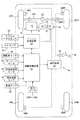
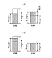
図19は前輪駆動用のハイブリッドエンジン及び後輪駆動用の電動発電機が搭載された四輪駆動式の車輌に適用された本発明による回生式制動制御装置の第四の実施形態に於ける制動制御ルーチンを示すゼネラルフローチャートであり、図20は前輪のタイヤ負荷率Ltrfが大きい場合(A)及び前輪のタイヤ負荷率Ltrfが小さい場合(B)について前輪及び後輪の回生定格と目標回生制動力(ハッチング部分)を示す説明図である。尚図19に於いて、図17に示されたステップに対応するステップには図17に於いて付されたステップ番号と同一のステップ番号が付されている。
【0136】
この実施形態に於いては、ステップ50〜70及びステップ100は上述の第三の実施形態の場合と同様に実行されるが、ステップ70に於いて演算される重みWs(前輪の重みWsf及び後輪の重みWsr)は、前輪のタイヤ負荷率Ltrfが小さいときには重みの比Wsf/Wsrが後輪用回生制動装置40の回生定格に対する前輪用回生制動装置30の回生定格の比又はこれに近い値であり、前輪のタイヤ負荷率Ltrfが大きいときには重みの比Wsf/Wsrが車輌の走行状態が効果的に安定な状態に維持し得る値になるよう、前輪のタイヤ負荷率Ltrfに基づき図18に示されている如きマップより演算される。
【0137】
またこの実施形態に於いては、ステップ950に於いて左右前輪の目標制動力Fxtfl及びFxtfrのうち小さい方の値の2倍として前輪の目標回生制動力Fbrgftが演算されると共に、左右後輪の目標制動力Fxtrl及びFxtrrのうち小さい方の値の2倍として後輪の目標回生制動力Fbrgrtが演算される。
【0138】
ステップ955に於いては前輪の目標回生制動力Fbrgftが前輪の回生制動装置30の回生定格により決定される最大回生制動力Fbrgflim(正の定数)よりも大きいか否かの判別、即ち前輪について回生制動に加えて摩擦制動が行われる必要があるか否かの判別が行われ、肯定判別が行われたときにはステップ960へ進み、否定判別が行われたときにはステップ965へ進む。
【0139】
ステップ960に於いては前輪の目標回生制動力Fbrgftが最大回生制動力Fbrgflimに修正されると共に、右前輪及び左前輪の目標摩擦制動力Fbptfr、Fbptflがそれぞれ下記の式61及び62に従って演算され、ステップ965に於いては前輪の目標回生制動力Fbrgftがステップ950に於いて演算された値に維持されると共に、右前輪及び左前輪の目標摩擦制動力Fbptfr、Fbptflが0に設定される。
Fbptfr=Fxtfr−Fbrgflim/2 ……(61)
Fbptfl=Fxtfl−Fbrgflim/2 ……(62)
【0140】
ステップ970に於いては後輪の目標回生制動力Fbrgrtが後輪の回生制動装置40の回生定格により決定される最大回生制動力Fbrgrlim(正の定数)よりも大きいか否かの判別、即ち後輪について回生制動に加えて摩擦制動が行われる必要があるか否かの判別が行われ、肯定判別が行われたときにはステップ975へ進み、否定判別が行われたときにはステップ980へ進む。
【0141】
ステップ975に於いては後輪の目標回生制動力Fbrgrtが最大回生制動力Fbrgrlimに修正されると共に、右後輪及び左後輪輪の目標摩擦制動力Fbptrr、Fbptrlがそれぞれ下記の式63及び64に従って演算され、ステップ980に於いては後輪の目標回生制動力Fbrgrtがステップ950に於いて演算された値に維持されると共に、右後輪及び左後輪の目標摩擦制動力Fbptrr、Fbptrlが0に設定される。
Fbptfr=Fxtfr−Fbrgflim/2 ……(63)
Fbptfl=Fxtfl−Fbrgflim/2 ……(64)
【0142】
かくして図示の第四の実施形態によれば、ステップ70に於いて演算される前輪の重みWsf及び後輪の重みWsrは、前輪のタイヤ負荷率Ltrfが小さいときには重みの比Wsf/Wsrが後輪用回生制動装置40の回生定格に対する前輪用回生制動装置30の回生定格の比又はこれに近い値であり、前輪のタイヤ負荷率Ltrfが大きいときには重みの比Wsf/Wsrが車輌の走行状態が効果的に安定な状態に維持し得る値になるよう、前輪のタイヤ負荷率Ltrfに応じて演算される。
【0143】
重みWsf及びWsrが車輌の走行状態が効果的に安定な状態に維持し得る一定の値に設定される場合には、例えば図20(A)に示されている如く、前輪の回生制動装置30の回生制動力に余裕があるが、後輪の目標制動力が後輪の回生制動装置の回生制動力を越えるような状況が生じ易く、かかる状況に於いては回生制動量が制限される。
【0144】
これに対し図示の第四の実施形態によれば、前輪のタイヤ負荷率Ltrfが小さいときには重みの比Wsf/Wsrが後輪用回生制動装置40の回生定格に対する前輪用回生制動装置30の回生定格の比又はこれに近い値であるので、図20(B)に示されている如く、前輪の回生制動装置30の回生制動力を増大させると共に後輪の目標制動力が後輪の回生制動装置の回生制動力を越えることを抑制することができ、これにより車輌全体としての回生制動量を増大させることができる。
【0145】
また図示の第四の実施形態によれば、前輪のタイヤ負荷率Ltrfが大きくなるにつれて重みの比Wsf/Wsrが車輌の走行状態が効果的に安定な状態に維持し得る値に漸次変化するので、前輪のタイヤ負荷率Ltrfが大きい領域に於いても重みの比Wsf/Wsrが後輪用回生制動装置40の回生定格に対する前輪用回生制動装置30の回生定格の比又はこれに近い値である場合に比して、確実に車輌の走行状態を安定な状態に制御することができる。
【0146】
更に図示の第四の実施形態によれば、前輪及び後輪の何れについても、目標回生制動力Fbrgtrl、Fbrgtrrがそれぞれ最大回生制動力Fbrgflim、Fbrgrlimを越える場合には、その超過分の制動力が摩擦制動力により補充され、これにより各車輪の制動力がステップ100に於いて演算された目標制動力になるよう制御されるので、前輪のタイヤ負荷率Ltrfに基づく重みの比Wsf、Wsrの可変制御及びこれに伴う回生制動力の制御に起因して車輌全体の制動力が変化すること及び車輌の走行状態の悪化を確実に防止することができる。
【0147】
第五の実施形態
図21はホイールインモータ式の四輪駆動車に適用された本発明による回生式制動制御装置の第五の実施形態を示す概略構成図である。尚図21に於いて、図1及び図14に示された部材に対応する部材にはこれらの図に於いて付された符号と同一の符号が付されている。
【0148】
この第五の実施形態に於いては、図21に示されている如く、左右の前輪26FL及び26FRはそれらの車輪に組み込まれたホイールインモータである電動発電機70FL及び70FRにより駆動され、電動発電機70FL及び70FRは駆動制御装置72により制御される。電動発電機70FL及び70FRはそれぞれ左右前輪の発電機としても機能し、回生発電機としての機能(回生制動)も駆動制御装置72により制御される。
【0149】
同様に、左右の後輪34RL及び34RRはそれらの車輪に組み込まれたホイールインモータである電動発電機70RL及び70RRにより駆動され、電動発電機70RL及び70RRも駆動制御装置72により制御される。また電動発電機70RL及び70RRもそれぞれ左右後輪の発電機として機能し、回生発電機としての機能(回生制動)も駆動制御装置72により制御される。
【0150】
尚図示の実施形態に於いては、電動発電機70FL及び70FRは互いに同一の回生定格を有し、電動発電機70RL及び70RRも互いに同一の回生定格を有し、電動発電機70FL及び70FRの回生定格は電動発電機70RL及び70RRの回生定格よりも大きい。
【0151】
図22は第五の実施形態に於ける制動制御ルーチンを示すゼネラルフローチャートである。尚図22に於いて、図17及び図19に示されたステップに対応するステップにはこれらの図に於いて付されたステップ番号と同一のステップ番号が付されている。
【0152】
この第五の実施形態に於いては、ステップ50〜70及びステップ100は上述の第四の実施形態の場合と同様に実行されるが、ステップ950に於いては各車輪の目標回生制動力Fbrgti(i=fr、fl、rr、rl)がそれぞれステップ100に於いて演算された目標制動力Fxtiに設定される。
【0153】
ステップ1005〜1015は例えば右前輪、左前輪、右後輪、左後輪の順に各車輪について実行され、ステップ1005に於いては目標回生制動力Fbrgtiが対応する電動発電機の回生定格により決定される最大回生制動力Fbrglimi(正の定数)(i=fr、fl、rr、rl)を越えているか否かの判別、即ち当該車輪について回生制動に加えて摩擦制動が行われる必要があるか否かの判別が行われ、肯定判別が行われたときにはステップ1010へ進み、否定判別が行われたときにはステップ1015へ進む。
【0154】
ステップ1010に於いては目標回生制動力Fbrgtiが最大回生制動力Fbrglimiに設定されると共に目標摩擦制動力Fbpiが目標制動力Fxtiより目標回生制動力Fbrgtiを減算した値に設定され、ステップ1015に於いては目標回生制動力Fbrgtiが目標制動力Fxtiに設定されると共に目標摩擦制動力Fbpiが0に設定される。
【0155】
かくして図示の第五の実施形態によれば、上述の第四の実施形態の場合と同様、ステップ70に於いて前輪の重みWsf及び後輪の重みWsrが前輪のタイヤ負荷率Ltrfに応じて可変設定され、前輪のタイヤ負荷率Ltrfが小さいほど、換言すれば車輪タイヤの力発生能力の余裕が大きいほど制動力の前後は配分が前輪寄りに制御され、重みの比Wsf/Wsrが後輪の電動発電機70RL及び70RRの回生定格に対する前輪の電動発電機70FL及び70FRの回生定格の比に近づけられるので、車輌がホイールインモータ式の四輪駆動車である場合に、前輪のタイヤ負荷率Ltrfが小さいときには車輌の走行状態を確実に安定な状態に維持しつつ車輌全体の回生量を増大させることができる。
【0156】
また図示の第五の実施形態によれば、上述の第四の実施形態の場合と同様、何れの車輪についても、目標回生制動力Fbrgtiが最大回生制動力Fbrglimiを越える場合には、その超過分の制動力が摩擦制動力により補充され、これにより各車輪の制動力がステップ100に於いて演算された目標制動力になるよう制御されるので、前輪のタイヤ負荷率Ltrfに基づく重みの比Wsf、Wsrの可変制御及びこれに伴う回生制動力の制御に起因して車輌全体の制動力が変化すること及び車輌の走行状態の悪化を確実に防止することができる。
【0157】
以上に於いては本発明を特定の実施形態について詳細に説明したが、本発明は上述の実施形態に限定されるものではなく、本発明の範囲内にて他の種々の実施形態が可能であることは当業者にとって明らかであろう。
【0158】
例えば上述の各実施形態に於いては、タイヤ負荷率は車輪タイヤの前後力Fxi、横力Fyi、路面の摩擦係数μ、車輪の接地荷重Wiに基づき上記式42に従ってタイヤが発生可能な力に対するタイヤが発生している力の比として演算され、タイヤ負荷率の指標値はタイヤ負荷率そのものであるが、例えばIを車輌のヨー慣性モーメントとし、Kf及びKrをそれぞれ前輪及び後輪のコーナリングパワーとし、Khをスタビリティファクタとし、Tcを時定数とし、sをラプラス演算子として下記の式65に従って演算される車輌モデルに基づく目標ヨーレートγrefと車輌の実際のヨーレートγとの偏差の大きさや、操舵角φ及び車速Vより演算される車輌モデルに基づく車輌の目標横加速度Gyrefと車輌の実際の横加速度Gyとの偏差の大きさの如く、タイヤ負荷率の指標値は車輌モデルに基づく車輌の目標状態量と車輌の実際の状態量との偏差の大きさであってもよい。
【数24】
尚この場合車輌モデルに基づく車輌の目標状態量と車輌の実際の状態量との偏差の大きさは車輌全体のタイヤ負荷率の指標値であるので、上述の各実施形態に於ける前輪のタイヤ負荷率Ltrfは上記偏差の大きさそのもの又はそれに比例する値に設定される。
【0160】
また上述の各実施形態に於いては、各車輪の目標制動力fxtiは車輌の運転状況に基づき車輌の目標前後力、目標横力、目標ヨーモーメントが演算され、車輌の走行安定性を維持しつつ車輌の目標前後力、目標横力、目標ヨーモーメントを達成するための制動力として演算されるようになっているが、各車輪の目標制動力fxtiは車輌の運転状況に基づき演算される限り、当技術分野に於いて公知の任意の態様にて演算されてよい。
【0161】
また上述の第一及び第二の実施形態に於いては、車輌の旋回度合として車輌のヨーレートγの絶対値が使用されるようになっているが、車輌の旋回度合は車輌の旋回の強さ乃至は程度を示すものであればよく、例えば上記目標ヨーレートγrefの絶対値、車輌の目標横加速度Gyrefの絶対値、車輌の実際の横加速度Gyの絶対値等であってもよい。
【0162】
また上述の第一及び第二の実施形態に於いては、タイヤ負荷率に基づく調整係数Rtrが前輪のタイヤ負荷率Ltrfに基づき図12に示されたグラフに対応するマップより演算されるようになっているが、前輪のタイヤ負荷率Ltrfが小さいときにはそれが大きいときに比してタイヤ負荷率に基づく調整係数Rtrが大きい値である限り、前輪のタイヤ負荷率Ltrfとタイヤ負荷率に基づく調整係数Rtrとの関係は図12に示された関係以外の関係であってもよい。
【0163】
同様に、上述の第三乃至第五の実施形態に於いては、前輪の重みWsf及び後輪の重みWsrが前輪のタイヤ負荷率Ltrfに基づき図18に示されたグラフに対応するマップより演算されるようになっているが、前輪のタイヤ負荷率Ltrfが小さいときにはそれが大きいときに比して前輪の重みWsfが大きい値であり若しくは後輪の重みWsrが小さい値である限り、前輪のタイヤ負荷率Ltrfと前輪の重みWsf及び後輪の重みWsrとの関係は図18に示された関係以外の関係であってもよい。
【図面の簡単な説明】
【図1】前輪駆動用のハイブリッドエンジンが搭載された前輪駆動式の車輌に適用された本発明による回生式制動制御装置の第一の実施形態を示す概略構成図である。
【図2】第一の実施形態に於ける制動制御ルーチンを示すゼネラルフローチャートである。
【図3】図2に示されたフローチャートのステップ100に於ける各車輪の目標制動力演算ルーチンを示すフローチャートである。
【図4】図3に示されたフローチャートのステップ150に於ける後輪スリップ角βr演算ルーチンを示すフローチャートである。
【図5】図3に示されたフローチャートのステップ200に於ける実際の前後力Fx、横力Fy、モーメントM演算ルーチンを示すフローチャートである。
【図6】図3に示されたフローチャートのステップ250に於ける目標前後力Fxa、横力Fya、モーメントMa演算ルーチンを示すフローチャートである。
【図7】図3に示されたフローチャートのステップ500に於ける目標スリップ率Si演算ルーチンを示すフローチャートである。
【図8】ドリフトアウト状態量DVと係数Kgとの間の関係を示すグラフである。
【図9】タイヤの発生力Ftiがタイヤの横方向に対しなす角度θi等を示す説明図である。
【図10】スリップ率が0であるときのタイヤのスリップ角βiに対する横力Ftyiの関係を示すグラフである。
【図11】スリップ角βiが0であるときのタイヤのスリップ率Siに対する前後力Ftxiの関係を示すグラフである。
【図12】前輪のタイヤ負荷率Ltrfとタイヤ負荷率に基づく調整係数Rtrとの間の関係を示すグラフである。
【図13】車輌のヨーレートγの絶対値と旋回度合に基づく調整係数Rstrとの間の関係を示すグラフである。
【図14】前輪駆動用のハイブリッドエンジン及び後輪駆動用の電動発電機が搭載された四輪駆動式の車輌に適用された本発明による回生式制動制御装置の第二の実施形態を示す概略構成図である。
【図15】第二の実施形態に於ける制動制御ルーチンを示すゼネラルフローチャートである。
【図16】図15に示されたフローチャートのステップ610に於いて実行される回生制動力の基本移行量演算ルーチンを示すフローチャートである。
【図17】前輪駆動用のハイブリッドエンジンが搭載された前輪駆動式の車輌に適用された本発明による回生式制動制御装置の第三の実施形態に於ける制動制御ルーチンを示すゼネラルフローチャートである。
【図18】前輪のタイヤ負荷率Ltrfと重みWsf、Wsrとの間の関係を示すグラフである。
【図19】前輪駆動用のハイブリッドエンジン及び後輪駆動用の電動発電機が搭載された四輪駆動式の車輌に適用された本発明による回生式制動制御装置の第四の実施形態に於ける制動制御ルーチンを示すゼネラルフローチャートである。
【図20】重みWsの補正前(A)及び重みWsの補正前(B)について前輪及び後輪の回生定格と目標回生制動力(ハッチング部分)を示す説明図である。
【図21】ホイールインモータ式の四輪駆動車に適用された本発明による回生式制動制御装置の第五の実施形態を示す概略構成図である。
【図22】第五の実施形態に於ける制動制御ルーチンを示すゼネラルフローチャートである。
【符号の説明】
10…ハイブリッドエンジン
12…ガソリンエンジン
14…電動発電機
28…エンジン制御装置
30…前輪の回生制動装置
32…ブレーキペダル
40…後輪用回生制動装置
42…電動発電機
44…摩擦制動装置
50…マスタシリンダ
52…制動制御装置
54…アクセルペダルセンサ
56…シフトポジションセンサ
58FR〜58RL…圧力センサ
60……操舵角センサ
62…ヨーレートセンサ
64…前後加速度センサ
66…横加速度センサ
68…車速センサ
70FL〜70RL…電動発電機
72…駆動制御装置[0001]
BACKGROUND OF THE INVENTION
The present invention relates to a braking control device for a vehicle such as an automobile, and more specifically, a friction braking device that individually applies a friction braking force to each wheel, and a regenerative braking device that applies a regenerative braking force to a plurality of wheels. The present invention relates to a regenerative braking control device.
[0002]
[Prior art]
As one of regenerative braking control devices for vehicles such as automobiles, the target braking force of each wheel is calculated based on the driving situation of the vehicle as described in, for example, the following
[0003]
The following
[Patent Document 1]
JP 2002-104156 A
[Patent Document 2]
JP 2001-169405 A
[Patent Document 3]
JP-A-9-104333
[Patent Document 4]
JP-A-7-203602
[Patent Document 5]
JP 2002-95108 A
[0004]
[Problems to be solved by the invention]
According to the conventional regenerative braking control device as described above, the regenerative braking force can be increased without deteriorating the running stability and turning performance of the vehicle, but the ratio between the target friction braking force and the target regenerative braking force Since the regenerative braking force is uniquely determined by the front-rear distribution ratio of the braking force, even if the wheel tire to which the regenerative braking force is applied has a margin for generating the braking force, the regenerative braking is effectively utilized. The power cannot be increased, so there is room for improvement in this respect in improving the fuel efficiency of the entire vehicle.
[0005]
The present invention has been made in view of the above-described problems in the conventional regenerative braking control device configured to control the regenerative braking force in accordance with the front-rear distribution ratio and the like. Is the tire load factor of the wheel to which the regenerative braking force is applied, i.e., the ratio of the force generated by the tire to the force that the tire can generate is small, and if the tire has a margin for generating the braking force, By increasing the regenerative braking force, the regenerative braking force is increased as compared with the case of the conventional regenerative braking control device.
[0006]
[Means for Solving the Problems]
According to the present invention, the main problem described above is a regenerative braking system for a vehicle having a friction braking device that individually applies a friction braking force to each wheel and a regenerative braking device that applies a regenerative braking force to a plurality of wheels. In the control device,Calculate the target braking force of each wheel for braking while maintaining a stable running state of the vehicle based on the driving situation of the vehicle, calculate the target friction braking force and the target regenerative braking force based on the target braking force,Calculate the tire load factor index value of the wheel to which the regenerative braking force is applied, and when the tire load factor index value is small compared to when it is largeBy increasing and correcting the target regenerative braking force of the wheel without changing the sum of the target friction braking force and the target regenerative braking force of the entire vehicleA regenerative braking control device for a vehicle (configuration of claim 1) characterized by increasing the regenerative braking force of the wheel while maintaining the braking force of the entire vehicle and the running stability of the vehicle, or individually for each wheel In a regenerative braking control device for a vehicle having a friction braking device that applies a friction braking force and a regenerative braking device that applies a regenerative braking force to a plurality of wheels, an index value of a tire load factor of a front wheel is calculated, Regenerative braking control device for a vehicle, wherein the front-rear distribution ratio of the braking force is changed by changing the regenerative braking force according to the index value of the tire load factor of the front wheels (claim)7To achieve this.
[0007]
According to the present invention, in order to effectively achieve the main problems described above, in the configuration of
[0008]
Further, according to the present invention, in order to effectively achieve the main problems described above, in the configurations of
[0009]
According to the present invention, in order to effectively achieve the main problems described above, the vehicle state quantity of the vehicle model is estimated on the basis of the driving state of the vehicle in the configuration of
[0010]
According to the present invention, in order to effectively achieve the main problems described above, the
[0011]
Further, according to the present invention, in order to effectively achieve the main problem described above, in the configuration of
[0013]
According to the present invention, in order to effectively achieve the main problems described above,7In this configuration, the front wheel regeneration capacity is larger than the rear wheel regeneration capacity, and when the index value of the tire load factor of the front wheels is small, the braking force distribution of the front wheels is larger than when it is large. It is comprised so that regenerative braking power may be changed according to the index value of the tire load factor of a front wheel.8Configuration).
[0014]
[Action and effect of the invention]
According to the configuration of
[0015]
According to the configuration of
[0016]
According to the configuration of claim 3, the tire longitudinal force and lateral force of each wheel, the ground contact load of each wheel, and the friction coefficient of the road surface are estimated, and based on these, the index value of the tire load factor of each wheel is calculated. Therefore, the force generated by each wheel tire is estimated based on the tire longitudinal force and lateral force of each wheel, and the force that can be generated by each wheel tire is calculated based on the ground load of each wheel and the friction coefficient of the road surface. Thus, the index value of the tire load factor of each wheel can be accurately calculated.
[0017]
According to the configuration of
[0018]
Moreover, according to the structure of the said
[0019]
Further, according to the configuration of the sixth aspect, as the turning degree of the vehicle is higher, the reduction amount of the increase correction amount of the target regenerative braking force is increased and the increase correction amount of the target regenerative braking force is reduced. The increase in the target regenerative braking force correction amount can be reduced as the performance decreases, and as a result, the increase in the target regenerative braking force and the resulting change in the distribution ratio of the braking force can cause a change in the turning of the vehicle. It can prevent effectively that driving stability falls.
[0021]
And the above claims7With this configuration, the index value of the tire load factor of the front wheels is calculated, and the regenerative braking force is increased by changing the front / rear distribution ratio of the braking force according to the index value of the tire load factor of the front wheels. The regenerative braking force can be increased by changing the front / rear distribution ratio of the braking force according to the force generation margin of the front wheel tire, thereby increasing the regenerative braking force while preventing a decrease in the running stability of the vehicle. .
[0022]
And the above claims8With this configuration, the front wheel regenerative amount is larger than the rear wheel regenerative amount, and when the index value of the tire load factor of the front wheels is small, the braking force distribution of the front wheels is larger than when the index value is large. Since the regenerative braking force is changed according to the index value of the tire load factor of the front wheels, the higher the front wheel tire force generation, the lower the running stability of the vehicle by making the front-rear braking force distribution ratio closer to the front wheels. In addition, the amount of regenerative braking of the entire vehicle can be increased by increasing the regenerative braking force of the front wheels.
[0023]
[Preferred embodiment of the problem solving means]
According to one preferred embodiment of the present invention, the
[0025]
According to another preferred embodiment of the invention, the above claims7Or8Based on the driving situation of the vehicleFor braking while maintaining a stable running state of the vehicleA target braking force of each wheel is calculated, and a target friction braking force and a target regenerative braking force are calculated based on the target braking force of each wheel (preferred aspect)2).
[0026]
According to another preferred embodiment of the present invention, the preferred embodiment described above.2In this configuration, the target longitudinal force, the target lateral force, and the target yaw moment of the vehicle are calculated based on the driving situation of the vehicle, and the target longitudinal force, the target lateral force, and the target yaw of the vehicle are maintained while maintaining the running stability of the vehicle. Configured to calculate a target braking force for each wheel to achieve the moment (preferred embodiment3).
[0027]
According to another preferred embodiment of the present invention, the preferred embodiment described above.3In the configuration, when the index value of the tire load factor of the front wheels is small, the target braking force of each wheel is calculated so that the braking force distribution of the front wheels is larger than when the index value is large (preferred mode)4).
[0028]
According to another preferred embodiment of the present invention, the
[0029]
According to another preferred embodiment of the present invention, the preferred embodiment described above.5In this configuration, the regenerative braking device is configured to be a common regenerative braking device for the left and right front wheels (preferred embodiment).6).
[0030]
According to another preferred embodiment of the present invention, the
[0031]
According to another preferred embodiment of the present invention, the preferred embodiment described above.7The regenerative braking device for the front wheels is a common regenerative braking device for the left and right front wheels, and the regenerative braking device for the rear wheels is a common regenerative braking device for the left and right front wheels.8).
[0032]
According to another preferred embodiment of the present invention, the
[0033]
The present invention will now be described in detail with reference to the accompanying drawings with respect to several preferred embodiments (hereinafter simply referred to as embodiments).
[0034]
First embodiment
FIG. 1 is a schematic configuration diagram showing a first embodiment of a regenerative braking control device according to the present invention applied to a front-wheel drive vehicle equipped with a hybrid engine.
[0035]
In FIG. 1,
[0036]
The
[0037]
In particular, in the illustrated embodiment, the
[0038]
The friction braking force of the left and right front wheels 26FL, 26FR and the left and right rear wheels 34RL, 34RR is controlled by controlling the braking pressures of the corresponding wheel cylinders 48FL, 48FR, 48RL, 48RR by the
[0039]
The
[0040]
Pressure sensors 58FR, 58FL, 58RR, 58RL for detecting the pressure Pi (i = fr, fl, rr, rl) in the wheel cylinders 48FR, 48FL, 48RR, 48RL of the respective wheels are located close to the wheels 10FR-10RL. Although not shown in the drawing, a
[0041]
Each
[0042]
As shown in the figure, a signal indicating the wheel cylinder pressure Pi detected by the pressure sensors 58FR to 58RL, a signal indicating the steering angle φ detected by the
[0043]
The
[0044]
As will be described in detail later, the
[0045]
The
[0046]
Then, the
[0047]
In particular, the
[0048]
The
[0049]
Note that the control of the operation mode of the
[0050]
Next, the basic principle of calculation of the target braking force of each wheel in the illustrated first embodiment will be described. The basic principle for calculating the target braking force is the same for other embodiments described later.
[0051]
First, the longitudinal force Ftxi and the lateral force Ftyi (i = fr, fl generated by the tires of each wheel) based on a brushed tire model that takes into account the reduction in lateral force during braking, load movement, tire slip angle, and road friction coefficient. , Rr, rl), and the tire longitudinal force change and lateral force change due to minute changes in the slip ratio.
[0052]
9, the generated force Fti of each
[Expression 1]
As shown in FIG. 10, the coefficient Kb is the slope at the origin of the graph of the lateral force Ftyi with respect to the tire slip angle βi when the slip ratio Si is 0, and the coefficient Ks is shown in FIG. As shown, the slope at the origin of the graph of the longitudinal force Ftxi with respect to the slip ratio Si of the tire when the slip angle βi is zero. Further, cos θ, sin θ, λ, and ξ are expressed by the following
[Expression 2]
The
[Equation 3]
Next, according to the following formulas 11-18, the front / rear force and lateral force (tire coordinate system) of each tire on the right front wheel (fr), left front wheel (fl), right rear wheel (rr), and left rear wheel (rl) are A longitudinal force Fxi and a lateral force Fyi acting on the center of gravity of the vehicle by being converted into a coordinate system are calculated, and a moment Mi is calculated. In the following equations, φf and φr are the steering angles of the front wheels and the rear wheels, Tr is the tread width of the vehicle, and Lf and Lr are respectively the center of gravity of the vehicle from the front wheel axle and the rear wheel axle. It is a distance, and T (φf) and T (φr) are values represented by the following
[0056]
[Expression 4]
Similarly, according to the following formulas 21 to 28, the front / rear force and lateral force partial differential values of the right front wheel (fr), left front wheel (fl), right rear wheel (rr), and left rear wheel (rl) (tires) A coordinate system is converted into a vehicle coordinate system to calculate partial differential values (derivatives) of longitudinal force and lateral force acting on the vehicle, and to calculate partial differential values (derivatives) of moments.
[0058]
[Equation 9]
Next, the longitudinal force Fx, lateral force Fy, and moment M of the vehicle generated when the slip rate of each wheel is the target slip rate Si are defined as the sum of the longitudinal force Fxi, lateral force Fyi, and moment Mi of each wheel as follows. An estimation operation is performed according to Equation 29.
[Formula 13]
Next, based on the following concepts (A) and (B), the target longitudinal force Fxa, the target lateral force Fya, and the target moment Ma are calculated according to the following
[0061]
(A) The target longitudinal force Fxt and the target moment Mt for stabilizing the vehicle behavior by the vehicle motion control are the longitudinal force Fxso and the moment generated when the motion control is not performed (when the slip ratio Si is 0). It is regarded as an additional amount with respect to Mso.
[0062]
(B) By reducing the lateral force Fyso when the motion is not controlled to the target lateral force Fya, the reduction of the lateral force during the motion control is reduced as much as possible.
[Expression 14]
The longitudinal force change dFx, lateral force change dFy, and moment change dM acting on the vehicle body due to the minute change dSi of the slip ratio of the four controlled wheels are expressed by the following
[Expression 15]
Next, the slip ratio Si for realizing the target longitudinal force Fxa, the target lateral force Fya, and the target moment Ma is calculated. However, since it is difficult to solve this slip rate analytically, it is obtained by the following convergence calculation.
[0065]
Assuming that the difference between the current longitudinal force, lateral force, moment and target longitudinal force, target lateral force, target moment is Δ, Δ is expressed by the following equation 33, and the slip rate correction amount that makes Δ equal to 0 Among them, the slip rate correction amount δS that minimizes the evaluation function L represented by the following equation 34 is obtained using T as a transport.
[0066]
[Expression 16]
[0067]
The first term on the right side of the above equation 34 is a term for limiting the slip rate correction amount δS of the target slip rate, the second term is a term for limiting the target slip rate, and the third term is the longitudinal force. This is a term for ensuring that the lateral force and the moment follow the target longitudinal force, the target lateral force and the target moment, respectively.
[0068]
The slip ratio correction amount δS that minimizes the evaluation function L of Expression 34 is expressed by Expression 35 below. Where Fx, Fy, and M are the longitudinal force, lateral force, and moment (Equation 29) generated at the current slip ratio of the controlled wheel, respectively, and Fxa, Fya, and Ma are the target longitudinal force, target lateral force, S is the target moment (formula 31), S and δS are the slip ratio (formula 36 below) and slip rate correction amount (formula 37 below) of each wheel, respectively, E is the longitudinal force and lateral force due to Δ and δS , The difference from the moment correction amount (
[0069]
δS = (Wds + Ws + JTWfJ)-1(-WsS + JTWfΔ) …… (35)
[Expression 17]
Therefore, by correcting the previous target slip ratio Sai with the slip ratio correction amount δSi, the target slip ratio Sai of the four wheels that achieves the target longitudinal force Fxa, the target lateral force Fya, and the target moment Ma can be calculated. Based on the target slip ratio Sai, the target braking force Fxti of each wheel can be calculated.
[0071]
Next, the braking control in the illustrated first embodiment will be described with reference to the flowchart shown in FIG. The control according to the flowchart shown in FIG. 2 is started by closing an ignition switch not shown in the figure, and is repeatedly executed at predetermined time intervals.
[0072]
First, in
[0073]
In
[0074]
In
[Expression 23]
In
[0076]
In
ΔFbrg = R · Fbbrgrt (43)
[0077]
In
[0078]
In
Fbrgft= Fbbrgft + ΔFbrg (44)
[0079]
In step 1000, the target friction braking force Fbpti (i = fr, fl, rr, rl) of each wheel is calculated according to the following equations 45-48.
Fbptfr = Fxtfr-Fbrgft / 2 (45)
Fbptfl = Fxtfl-Fbrgft / 2 (46)
Fbptrr = Fxtrr−ΔFbrg / 2 (47)
Fbptrl = Fxtrl−ΔFbrg / 2 (48)
[0080]
In step 1050, the front wheel target regenerative braking force FbrgftIs output to the
[0081]
In step 1050, the target braking pressure Pbpti of each wheel is calculated based on the target friction braking force Fbpti of each wheel, and the
[0082]
Next, the target braking force calculation routine for each wheel in
[0083]
First, at step 150, the slip angle βr of the rear wheel is calculated according to the routine shown in FIG. 4, and at step 200, the target calculated at the
[0084]
In step 300, the longitudinal force change and lateral force change of each wheel are calculated according to the above-described
[0085]
In step 350, the longitudinal force, lateral force, and moment target values Fxa, Fya, Ma and the actual values Fx, Fy, M are respectively deviated from the actual values Fx, Fy, M in accordance with the above equation 33. Correction amount δFy and moment correction amount δM.
[0086]
In
[0087]
In step 450, the corrected target slip ratio Sai of each wheel is calculated as the sum (Sai + δSi) of the previous target slip ratio Sai and the correction amount δSai of the slip ratio calculated in
[0088]
In
[0089]
In step 155 of the routine for calculating the slip angle βr of the rear wheel shown in FIG. 4, the deviation of the lateral acceleration, that is, the slip of the vehicle, is obtained as the deviation Gy−Vγ between the lateral acceleration Gy and the product Vγ of the vehicle speed V and the yaw rate γ. The acceleration Vyd is calculated and the side-slip acceleration Vyd is integrated to calculate the side-slip speed Vy of the vehicle body, and the slip angle of the vehicle body as the ratio Vy / Vx of the vehicle body side-slip velocity Vy to the vehicle body longitudinal speed Vx (= vehicle speed V) β is calculated.
[0090]
In step 160, the rear wheel slip angle βr is calculated according to the following equation 49, with Lr being the distance in the vehicle longitudinal direction between the center of gravity of the vehicle and the rear wheel axle. The slip angle βr of the rear wheel is positive when the slip direction of the rear wheel is counterclockwise with respect to the rolling direction of the rear wheel.
βr = β-Lrγ / V (49)
[0091]
In step 165, it is determined whether or not the slip angle βr of the rear wheel exceeds the reference value βrc with the reference value βrc as a positive constant. If a negative determination is made, the process proceeds to step 175, where an affirmative determination is made. In step 170, the slip angle βr of the rear wheel is set to the reference value βrc.
[0092]
Similarly, in step 175, it is determined whether or not the slip angle βr of the rear wheel is less than -βrc. If a negative determination is made, the process proceeds directly to step 200, and if an affirmative determination is made, the process proceeds to step 200. At 180, the slip angle βr of the rear wheel is set to -βrc, and then the routine proceeds to step 200.
[0093]
In step 205 of the vehicle longitudinal force Fx, lateral force Fy, and moment M calculation routine at the target slip ratio shown in FIG. 5, the actual steering angle φf of the front wheels is calculated based on the steering angle φ, and The front wheel slip angle βf is calculated according to the following
βf = −φf + β + Lfγ / V (50)
[0094]
In
μ = (Gx2+ Gy2)1/2/ G (51)
[0095]
In step 215, the load movement amount ΔWi of each wheel is calculated based on the longitudinal acceleration Gx and the lateral acceleration Gy of the vehicle body in a manner well known in the art, and the support load Wi of each wheel is calculated based on the wheel load. Is calculated as the sum (Wsi + ΔWi) of the static load Wsi and the load movement amount ΔWi.
[0096]
In step 220, the determination value ξi of the grip state of each wheel is calculated according to the
[0097]
In
[0098]
In step 255 of the vehicle target longitudinal force Fxa, target lateral force Fya, target moment Ma calculation routine shown in FIG. 6, the target yaw rate γc according to the following
γc = Vφ / (1 + KhV2) H ...... (52)
γt = γc / (1 + Ts) (53)
[0099]
In step 260, the drift-out amount DV is calculated according to the following
DV = (γt−γ) (54)
DV = H (γt−γ) / V (55)
[0100]
In
[0101]
In
Mt = Km1 (β−βt) + Km2 (βd−βtd) (56)
[0102]
In step 280, the target longitudinal force Fxt for behavior control is calculated as the product of the coefficient Kg, the vehicle mass Mass, and the gravitational acceleration g according to the following equation 57.
Fxt = -KgMassg (57)
[0103]
In step 285, the longitudinal force Fxso, lateral force Fyso, and moment Mso of the vehicle when the slip ratio Si of each wheel is 0 are calculated according to the
[0104]
In step 505 of the target slip ratio correction calculation routine shown in FIG. 7, it is determined whether the target moment Ma is negative, the rear wheel slip angle βr is positive, and the vehicle yaw rate γ is positive. When a negative determination is made, the process proceeds to step 510. When an affirmative determination is made, the target slip ratios Srr and Srl of the rear wheels are set to 0 in step 515, and then step 550 is performed. Proceed to
[0105]
In step 510, it is determined whether the target moment Ma is positive, the rear wheel slip angle βr is negative, and the vehicle yaw rate γ is negative. Proceed to 515, and if a negative determination is made, proceed directly to step 550.
[0106]
Thus, according to the first embodiment shown in the figure, in
[0107]
In
[0108]
In
[0109]
Therefore, according to the first embodiment shown in the figure, the adjustment factor Rtr based on the tire load factor Ltrf of the front wheel is calculated to a larger value as the tire load factor Ltrf of the front wheel is smaller and the force that can be generated by the front wheel is larger. As a result, the shift amount ΔFbrg of the regenerative braking force from the rear wheels to the front wheels is increased. Therefore, the
[0110]
According to the illustrated first embodiment, the regenerative braking force of the left and right front wheels is increased by the same amount, and the amount of friction braking force of the left and right rear wheels is reduced by the same amount as the amount of increase of the regenerative braking force of the left and right front wheels. As a result, the yaw rate of the vehicle and the braking force of the entire vehicle are not changed due to a change in the front-rear distribution of the braking force, and the margin for generating the lateral force of the rear wheel is increased without bringing the front wheel to the limit state. Therefore, the regeneration amount can be increased while reliably maintaining the running stability of the vehicle and the deceleration of the vehicle.
[0111]
Further, according to the first embodiment shown in the drawing, the slip angle βr of the rear wheel is calculated in step 150, and the current longitudinal force Fx, lateral force Fy, and moment M of the vehicle are calculated in step 200, The sum of the vehicle longitudinal force Fxso, lateral force Fyso, moment Mso and the target longitudinal force Fxt and target moment Mt for stabilizing the behavior of the vehicle when the slip ratio Si of each wheel is 0 in
[0112]
In step 350, the difference between the target longitudinal force Fxa and the actual longitudinal force Fx, the difference between the target lateral force Fya and the actual lateral force Fy, the difference between the target moment Ma and the actual moment M, and the derivative ∂Fxi / ∂Si, ∂Fyi / ∂Si, ∂Mi / ∂Si, the front-rear force correction amount δFx, the lateral force correction amount δFy, and the moment correction amount δM are calculated by convergence calculation. The slip rate correction amount δSi of each wheel to achieve the correction amount of the lateral force and moment is calculated, and the target slip rate previously calculated in step 450 is corrected with the slip rate correction amount δSi. Thus, the target slip ratio Sai of this time is calculated, and in
[0113]
Therefore, according to the illustrated first embodiment, the braking force of each wheel is set so that the longitudinal force Fx of the vehicle becomes the target longitudinal force Fxa, the lateral force Fy becomes the target lateral force Fya, and the moment M becomes the target moment Ma. Therefore, the amount of regeneration by the
[0114]
Further, according to the first embodiment shown in the figure, the slip ratio correction amount δSi of each wheel sets the difference Δ between the current vehicle longitudinal force, lateral force, moment and target longitudinal force, target lateral force, and target moment to zero. Of the slip rate correction amounts to be calculated, the slip rate correction amount of each wheel that minimizes the evaluation function L expressed by the above equation 34 is calculated according to the above equation 35. There is no need to set up many maps that show the correspondence between the wheel slip rate and the longitudinal force, lateral force, and moment to stabilize the vehicle movement, and this makes it easy to configure the motion control device. The slip ratio Si of each wheel that achieves the target longitudinal force, the target lateral force, and the target moment can be calculated more quickly than when the slip ratio Si is calculated by analysis. Response delay in running state Ku can be maintained in a stable state, the operational effects can be obtained also in other embodiments described later.
[0115]
Second embodiment
FIG. 14 is a schematic diagram showing a second embodiment of a regenerative braking control device according to the present invention applied to a four-wheel drive vehicle equipped with a front-wheel drive hybrid engine and a rear-wheel drive motor generator. FIG. In FIG. 14, members corresponding to those shown in FIG. 1 are denoted by the same reference numerals as those in FIG.
[0116]
In the second embodiment, the left and right rear wheels 34RL and 34RR are connected to the rear wheel regenerative braking device via the left and right rear wheel axles 36RL and 36RR and the rear wheel differential 38 as required when the vehicle is driven. 40, and the rotation of the left and right rear wheels 34RL and 34RR is transmitted to the
[0117]
FIG. 15 is a general flowchart showing a braking control routine in the second embodiment, and FIG. 16 is a basic transition amount calculation routine for the regenerative braking force executed in step 610 of the flowchart shown in FIG. It is a flowchart to show. In FIG. 15, steps corresponding to the steps shown in FIG. 2 are assigned the same step numbers as those shown in FIG.
[0118]
In this embodiment, the steps other than step 610 and step 850 executed after
[0119]
In
ΔFbrg = R · ΔFbbrg (58)
[0120]
In step 612 of the flowchart shown in FIG. 16, the rear wheel target regenerative braking force Fbrgrt is larger than the maximum regenerative braking force Fbrgrlim (a positive constant) determined by the regenerative rating of the rear wheel
[0121]
In step 614, it is determined whether or not the target regenerative braking force Fbrgft of the front wheels is less than the maximum regenerative braking force Fbrgflim (positive constant) determined by the regenerative rating of the
[0122]
In step 618, the excessive regenerative braking force ΔFbrgr of the rear wheel is calculated according to the following equation 59, and the regenerative braking force ΔFbrgf that can be transferred from the rear wheel to the front wheel is calculated according to the following
ΔFbrgr = Fbrgrt−Fbrgrlim (59)
ΔFbrgf = Fbrgft−Fbrgflim (60)
[0123]
In step 620, the basic transition amount ΔFbbrg of the regenerative braking force is set to the excess regenerative braking force ΔFbrgr, and in step 622, the basic transition amount ΔFbbrg of the regenerative braking force is set to the regenerative braking force ΔFbrgf that can be increased. When 616, 618 or 620 is completed, the process proceeds to step 650.
[0124]
Thus, according to the second embodiment shown in the figure, in step 610, the regenerative braking force is within the range of the regenerative rating of the front wheel
[0125]
In particular, according to the second embodiment shown in the drawing, it is necessary to transfer the regenerative braking force from the rear wheel to the front wheel from the point of regenerative rating in accordance with the flowchart shown in FIG. When it is determined that the regenerative braking force to the front wheels can be transferred and the excessive regenerative braking force ΔFbrgr of the rear wheels is less than the regenerative braking force ΔFbrgf that can be transferred from the rear wheels to the front wheels, the regenerative braking is performed in step 620. Since the power basic shift amount ΔFbbrg is set to the rear wheel excess regenerative braking force ΔFbrgr, the rear wheel basic regenerative braking force Fbbrgrt exceeds the regenerative rating of the rear wheel
[0126]
According to the first and second embodiments described above, in step 750, the adjustment coefficient Rstr based on the turning degree is based on the absolute value of the yaw rate γ of the vehicle so as to decrease as the absolute value of the yaw rate γ of the vehicle increases. In
[0127]
Further, according to the first and second embodiments, the target regenerative braking force Fbrgt and the target of the left and right front wheels calculated in
[0128]
Further, according to the first and second embodiments, the tire load factors Ltrfr and Ltrfl of the left and right front wheels are calculated in
[0129]
Third embodiment
FIG. 17 is a general flowchart showing a braking control routine in the third embodiment of the regenerative braking control device according to the present invention applied to a front wheel drive type vehicle equipped with a front wheel drive hybrid engine. 18 is a graph showing the relationship between the tire load factor Ltrf of the front wheels and the weight Ws. In FIG. 17, steps corresponding to the steps shown in FIG. 2 are given the same step numbers as the step numbers given in FIG. 2.
[0130]
In this embodiment, the tire load factor Ltrf of the front wheels is calculated in the same manner as in
[0131]
In this embodiment,
[0132]
Further, in this embodiment, the target regenerative braking force Fbrgft for the front wheels is calculated as twice the smaller one of the target braking forces Fxtfl and Fxtfr for the left and right front wheels in
[0133]
Thus, according to the third embodiment shown in the drawing, in
[0134]
Further, according to the third embodiment shown in the figure, the calculation of the adjustment coefficient Rstr based on the turning degree of the vehicle and the adjustment of the transfer amount of the regenerative braking force from the rear wheel to the front wheel based on this are unnecessary. Control of braking force front / rear distribution based on the tire load factor of the front wheels and regeneration from the rear wheels to the front wheels without affecting the performance and more easily than in the case of the first and second embodiments described above. The shift amount of the braking force can be controlled.
[0135]
Fourth embodiment
FIG. 19 shows the braking in the fourth embodiment of the regenerative braking control device according to the present invention applied to a four-wheel drive vehicle equipped with a hybrid engine for driving front wheels and a motor generator for driving rear wheels. FIG. 20 is a general flowchart showing a control routine. FIG. 20 shows a case where the front wheel tire load factor Ltrf is large (A) and a case where the front wheel tire load factor Ltrf is small (B). It is explanatory drawing which shows (hatching part). In FIG. 19, steps corresponding to the steps shown in FIG. 17 are assigned the same step numbers as the step numbers given in FIG.
[0136]
In this embodiment, steps 50 to 70 and step 100 are executed in the same manner as in the third embodiment described above. However, the weight Ws calculated in step 70 (the front wheel weight Wsf and the rear wheel weight Wsf) is calculated. The wheel weight Wsr) is a ratio of the weight ratio Wsf / Wsr to the regenerative rating of the
[0137]
In this embodiment, in
[0138]
In step 955, it is determined whether or not the front wheel target regenerative braking force Fbrgft is greater than the maximum regenerative braking force Fbrgflim (a positive constant) determined by the regenerative rating of the front wheel
[0139]
In
Fbptfr = Fxtfr-Fbrgflim / 2 (61)
Fbptfl = Fxtfl-Fbrgflim / 2 (62)
[0140]
In
[0141]
In
Fbptfr = Fxtfr-Fbrgflim / 2 (63)
Fbptfl = Fxtfl-Fbrgflim / 2 (64)
[0142]
Thus, according to the illustrated fourth embodiment, the front wheel weight Wsf and the rear wheel weight Wsr calculated in
[0143]
When the weights Wsf and Wsr are set to constant values that can maintain the vehicle running state effectively in a stable state, for example, as shown in FIG. However, there is a tendency that the rear brake target braking force exceeds the regenerative braking force of the rear wheel regenerative braking device, and the regenerative braking amount is limited in this situation.
[0144]
On the other hand, according to the fourth embodiment shown in the figure, when the tire load factor Ltrf of the front wheels is small, the weight ratio Wsf / Wsr is such that the regenerative rating of the
[0145]
Further, according to the fourth embodiment shown in the figure, as the tire load factor Ltrf of the front wheels increases, the weight ratio Wsf / Wsr gradually changes to a value at which the running state of the vehicle can be effectively maintained. Even in the region where the tire load factor Ltrf of the front wheels is large, the weight ratio Wsf / Wsr is the ratio of the regenerative rating of the
[0146]
Further, according to the fourth embodiment shown in the figure, when the target regenerative braking forces Fbrgtrl and Fbrgtrr exceed the maximum regenerative braking forces Fbrgflim and Fbrgrlim for both the front wheels and the rear wheels, the excess braking force is obtained. Since the braking force of each wheel is controlled so as to become the target braking force calculated in
[0147]
Fifth embodiment
FIG. 21 is a schematic diagram showing a fifth embodiment of a regenerative braking control device according to the present invention applied to a wheel-in-motor four-wheel drive vehicle. In FIG. 21, the members corresponding to those shown in FIGS. 1 and 14 are denoted by the same reference numerals as those shown in these drawings.
[0148]
In the fifth embodiment, as shown in FIG. 21, the left and right front wheels 26FL and 26FR are driven by motor generators 70FL and 70FR, which are wheel-in motors incorporated in these wheels. The generators 70FL and 70FR are controlled by a
[0149]
Similarly, the left and right rear wheels 34RL and 34RR are driven by motor generators 70RL and 70RR which are wheel-in motors incorporated in these wheels, and the motor generators 70RL and 70RR are also controlled by the
[0150]
In the illustrated embodiment, the motor generators 70FL and 70FR have the same regenerative rating, the motor generators 70RL and 70RR have the same regenerative rating, and the motor generators 70FL and 70FR are regenerated. The rating is larger than the regenerative rating of the motor generators 70RL and 70RR.
[0151]
FIG. 22 is a general flowchart showing a braking control routine in the fifth embodiment. In FIG. 22, steps corresponding to the steps shown in FIGS. 17 and 19 are given the same step numbers as those shown in these drawings.
[0152]
In the fifth embodiment, steps 50 to 70 and step 100 are executed in the same manner as in the fourth embodiment described above. However, in
[0153]
Steps 1005 to 1015 are executed for each wheel in the order of, for example, the right front wheel, the left front wheel, the right rear wheel, and the left rear wheel. In step 1005, the target regenerative braking force Fbrgti is determined by the regenerative rating of the corresponding motor generator. The maximum regenerative braking force Fbrglimi (positive constant) (i = fr, fl, rr, rl) is exceeded, that is, whether or not the wheel needs to be subjected to friction braking in addition to regenerative braking. When a positive determination is made, the process proceeds to step 1010. When a negative determination is made, the process proceeds to step 1015.
[0154]
In step 1010, the target regenerative braking force Fbrgti is set to the maximum regenerative braking force Fbrglimi, and the target friction braking force Fbpi is set to a value obtained by subtracting the target regenerative braking force Fbrgti from the target braking force Fxti. In this case, the target regenerative braking force Fbrgti is set to the target braking force Fxti and the target friction braking force Fbpi is set to 0.
[0155]
Thus, according to the fifth embodiment shown in the figure, as in the case of the fourth embodiment described above, in
[0156]
Further, according to the fifth embodiment shown in the figure, as in the case of the fourth embodiment described above, if the target regenerative braking force Fbrgti exceeds the maximum regenerative braking force Fbrglimi for any wheel, the excess amount is exceeded. Since the braking force of each wheel is supplemented by the friction braking force, and the braking force of each wheel is controlled to become the target braking force calculated in
[0157]
Although the present invention has been described in detail with respect to specific embodiments, the present invention is not limited to the above-described embodiments, and various other embodiments are possible within the scope of the present invention. It will be apparent to those skilled in the art.
[0158]
For example, in each of the above-described embodiments, the tire load factor is based on the force that the tire can generate according to the
[Expression 24]
In this case, since the magnitude of the deviation between the target state quantity of the vehicle based on the vehicle model and the actual state quantity of the vehicle is an index value of the tire load factor of the entire vehicle, the front wheel tire in each of the above embodiments The load factor Ltrf is set to the magnitude of the deviation itself or a value proportional thereto.
[0160]
In each of the above-described embodiments, the target braking force fxti of each wheel is calculated based on the vehicle driving conditions such as the target longitudinal force, the target lateral force, and the target yaw moment to maintain the vehicle running stability. However, although it is calculated as a braking force for achieving the target longitudinal force, target lateral force, and target yaw moment of the vehicle, the target braking force fxti of each wheel is calculated as long as it is calculated based on the driving situation of the vehicle. It may be computed in any manner known in the art.
[0161]
In the first and second embodiments described above, the absolute value of the yaw rate γ of the vehicle is used as the turning degree of the vehicle, but the turning degree of the vehicle is the strength of turning of the vehicle. The absolute value of the target yaw rate γref, the absolute value of the target lateral acceleration Gyref of the vehicle, the absolute value of the actual lateral acceleration Gy of the vehicle, or the like may be used.
[0162]
In the first and second embodiments described above, the adjustment coefficient Rtr based on the tire load factor is calculated from the map corresponding to the graph shown in FIG. 12 based on the tire load factor Ltrf of the front wheels. However, when the tire load factor Ltrf for the front wheels is small, the adjustment based on the tire load factor Ltrf for the front wheels and the tire load factor as long as the adjustment factor Rtr based on the tire load factor is larger than when the tire load factor Ltrf is large. The relationship with the coefficient Rtr may be a relationship other than the relationship shown in FIG.
[0163]
Similarly, in the third to fifth embodiments described above, the front wheel weight Wsf and the rear wheel weight Wsr are calculated from the map corresponding to the graph shown in FIG. 18 based on the front wheel tire load factor Ltrf. However, as long as the tire load factor Ltrf of the front wheel is small, the front wheel weight Wsf is larger than that when it is large, or as long as the rear wheel weight Wsr is small, the front wheel weight The relationship between the tire load factor Ltrf, the front wheel weight Wsf, and the rear wheel weight Wsr may be other than the relationship shown in FIG.
[Brief description of the drawings]
FIG. 1 is a schematic configuration diagram showing a first embodiment of a regenerative braking control device according to the present invention applied to a front-wheel drive type vehicle equipped with a front-wheel drive hybrid engine.
FIG. 2 is a general flowchart showing a braking control routine in the first embodiment.
FIG. 3 is a flowchart showing a target braking force calculation routine for each wheel in
FIG. 4 is a flowchart showing a rear wheel slip angle βr calculation routine in step 150 of the flowchart shown in FIG. 3;
FIG. 5 is a flowchart showing an actual longitudinal force Fx, lateral force Fy, and moment M calculation routine in step 200 of the flowchart shown in FIG. 3;
6 is a flowchart showing a routine for calculating a target longitudinal force Fxa, a lateral force Fya, and a moment Ma in
7 is a flowchart showing a target slip ratio Si calculation routine in
FIG. 8 is a graph showing a relationship between a drift-out state quantity DV and a coefficient Kg.
FIG. 9 is an explanatory diagram showing an angle θi formed by a tire generation force Fti with respect to the tire lateral direction, and the like.
FIG. 10 is a graph showing the relationship of the lateral force Ftyi to the tire slip angle βi when the slip ratio is zero.
FIG. 11 is a graph showing the relationship between the longitudinal force Ftxi and the tire slip ratio Si when the slip angle βi is zero.
FIG. 12 is a graph showing a relationship between a tire load factor Ltrf of a front wheel and an adjustment coefficient Rtr based on the tire load factor.
FIG. 13 is a graph showing the relationship between the absolute value of the yaw rate γ of the vehicle and the adjustment coefficient Rstr based on the turning degree.
FIG. 14 is a schematic diagram showing a second embodiment of a regenerative braking control device according to the present invention applied to a four-wheel drive vehicle equipped with a front-wheel drive hybrid engine and a rear-wheel drive motor generator. It is a block diagram.
FIG. 15 is a general flowchart showing a braking control routine in the second embodiment.
FIG. 16 is a flowchart showing a regenerative braking force basic shift amount calculation routine executed in step 610 of the flowchart shown in FIG. 15;
FIG. 17 is a general flowchart showing a braking control routine in a third embodiment of the regenerative braking control device according to the present invention applied to a front wheel drive type vehicle equipped with a front wheel drive hybrid engine.
FIG. 18 is a graph showing a relationship between a tire load factor Ltrf of front wheels and weights Wsf and Wsr.
FIG. 19 shows a regenerative braking control apparatus according to a fourth embodiment of the present invention applied to a four-wheel drive vehicle equipped with a front-wheel drive hybrid engine and a rear-wheel drive motor generator. It is a general flowchart which shows a braking control routine.
FIG. 20 is an explanatory diagram showing regenerative ratings and target regenerative braking force (hatched portion) of the front wheels and rear wheels before correction of weight Ws (A) and before correction of weight Ws (B).
FIG. 21 is a schematic configuration diagram showing a fifth embodiment of a regenerative braking control device according to the present invention applied to a wheel-in-motor four-wheel drive vehicle.
FIG. 22 is a general flowchart showing a braking control routine in a fifth embodiment.
[Explanation of symbols]
10 ... Hybrid engine
12 ... gasoline engine
14 ... Motor generator
28. Engine control device
30 ... Regenerative braking device for front wheels
32 ... Brake pedal
40. Regenerative braking device for rear wheels
42 ... Motor generator
44. Friction braking device
50 ... Master cylinder
52. Braking control device
54 ... Accelerator pedal sensor
56 ... Shift position sensor
58FR to 58RL ... Pressure sensor
60 …… Steering angle sensor
62 ... Yaw rate sensor
64. Longitudinal acceleration sensor
66 ... Lateral acceleration sensor
68 ... Vehicle speed sensor
70FL ~ 70RL ... Motor generator
72. Drive control device
Claims (8)
Priority Applications (1)
| Application Number | Priority Date | Filing Date | Title |
|---|---|---|---|
| JP2003030699A JP3997923B2 (en) | 2003-02-07 | 2003-02-07 | Regenerative braking control device for vehicle |
Applications Claiming Priority (1)
| Application Number | Priority Date | Filing Date | Title |
|---|---|---|---|
| JP2003030699A JP3997923B2 (en) | 2003-02-07 | 2003-02-07 | Regenerative braking control device for vehicle |
Publications (2)
| Publication Number | Publication Date |
|---|---|
| JP2004242460A JP2004242460A (en) | 2004-08-26 |
| JP3997923B2 true JP3997923B2 (en) | 2007-10-24 |
Family
ID=32957510
Family Applications (1)
| Application Number | Title | Priority Date | Filing Date |
|---|---|---|---|
| JP2003030699A Expired - Fee Related JP3997923B2 (en) | 2003-02-07 | 2003-02-07 | Regenerative braking control device for vehicle |
Country Status (1)
| Country | Link |
|---|---|
| JP (1) | JP3997923B2 (en) |
Families Citing this family (8)
| Publication number | Priority date | Publication date | Assignee | Title |
|---|---|---|---|---|
| US7409280B2 (en) * | 2004-01-15 | 2008-08-05 | Nissan Motor Co., Ltd. | Vehicle braking control apparatus |
| JP4346089B2 (en) * | 2005-01-13 | 2009-10-14 | 本田技研工業株式会社 | Vehicle motion state control device |
| JP2006306163A (en) * | 2005-04-26 | 2006-11-09 | Fuji Heavy Ind Ltd | Vehicle behavior controlling device |
| JP4735058B2 (en) * | 2005-05-31 | 2011-07-27 | 日産自動車株式会社 | Vehicle weight estimation device |
| JP5908779B2 (en) | 2012-05-01 | 2016-04-26 | 日立オートモティブシステムズ株式会社 | Brake control device and brake control method |
| JP2017077753A (en) * | 2015-10-19 | 2017-04-27 | トヨタ自動車株式会社 | Vehicle control device |
| GB2562308B (en) * | 2017-05-12 | 2022-10-26 | Arrival Ltd | Regenerative braking control system |
| JP6847492B2 (en) * | 2017-06-02 | 2021-03-24 | 日立Astemo株式会社 | Electric vehicle control device, electric vehicle control system, and electric vehicle control method |
-
2003
- 2003-02-07 JP JP2003030699A patent/JP3997923B2/en not_active Expired - Fee Related
Also Published As
| Publication number | Publication date |
|---|---|
| JP2004242460A (en) | 2004-08-26 |
Similar Documents
| Publication | Publication Date | Title |
|---|---|---|
| JP3937524B2 (en) | Vehicle braking / driving force control device | |
| JP3458734B2 (en) | Vehicle motion control device | |
| JP3623456B2 (en) | Vehicle travel control device | |
| US8655563B2 (en) | Braking/driving force controller of vehicle | |
| JP4131268B2 (en) | Vehicle braking / driving force control device | |
| KR101697809B1 (en) | Method and braking system for influencing driving dynamics by means of braking and driving operations | |
| US20090012686A1 (en) | Braking-Driving Force Control Device of Vehicle | |
| JP2006335171A (en) | Driving/braking force control device for vehicle | |
| EP1521146A2 (en) | Integrated control apparatus for vehicle | |
| JP3878840B2 (en) | Vehicle travel control device | |
| JP3621842B2 (en) | Vehicle motion control device | |
| JP2006264628A (en) | Vehicular braking/driving force control system | |
| US8315774B2 (en) | Vehicle driving-force control device | |
| US8135524B2 (en) | Vehicle driving force control device | |
| JP2020050024A (en) | Vehicular turn behavior control apparatus | |
| JP3997923B2 (en) | Regenerative braking control device for vehicle | |
| JP6329105B2 (en) | Driving force control device for four-wheel drive vehicle | |
| JP3827837B2 (en) | Vehicle motion control device | |
| JP5256130B2 (en) | Tire force control device for four-wheel drive vehicles | |
| JP4114065B2 (en) | Four-wheel drive vehicle behavior control device | |
| JP4055225B2 (en) | Vehicle braking / driving force control device | |
| JP3948076B2 (en) | Estimation method of friction circle radius of wheel | |
| JP2004025996A (en) | Motion control device for vehicle | |
| JP3827265B2 (en) | Brake control device for vehicle | |
| JP2009046091A (en) | Braking force control device, driving force control device, and braking and driving force control device |
Legal Events
| Date | Code | Title | Description |
|---|---|---|---|
| A621 | Written request for application examination |
Free format text: JAPANESE INTERMEDIATE CODE: A621 Effective date: 20051220 |
|
| RD02 | Notification of acceptance of power of attorney |
Free format text: JAPANESE INTERMEDIATE CODE: A7422 Effective date: 20051226 |
|
| RD04 | Notification of resignation of power of attorney |
Free format text: JAPANESE INTERMEDIATE CODE: A7424 Effective date: 20051227 |
|
| A977 | Report on retrieval |
Free format text: JAPANESE INTERMEDIATE CODE: A971007 Effective date: 20061013 |
|
| A131 | Notification of reasons for refusal |
Free format text: JAPANESE INTERMEDIATE CODE: A131 Effective date: 20061121 |
|
| A521 | Written amendment |
Free format text: JAPANESE INTERMEDIATE CODE: A523 Effective date: 20070119 |
|
| TRDD | Decision of grant or rejection written | ||
| A01 | Written decision to grant a patent or to grant a registration (utility model) |
Free format text: JAPANESE INTERMEDIATE CODE: A01 Effective date: 20070717 |
|
| A61 | First payment of annual fees (during grant procedure) |
Free format text: JAPANESE INTERMEDIATE CODE: A61 Effective date: 20070730 |
|
| R151 | Written notification of patent or utility model registration |
Ref document number: 3997923 Country of ref document: JP Free format text: JAPANESE INTERMEDIATE CODE: R151 |
|
| FPAY | Renewal fee payment (event date is renewal date of database) |
Free format text: PAYMENT UNTIL: 20100817 Year of fee payment: 3 |
|
| FPAY | Renewal fee payment (event date is renewal date of database) |
Free format text: PAYMENT UNTIL: 20100817 Year of fee payment: 3 |
|
| FPAY | Renewal fee payment (event date is renewal date of database) |
Free format text: PAYMENT UNTIL: 20110817 Year of fee payment: 4 |
|
| FPAY | Renewal fee payment (event date is renewal date of database) |
Free format text: PAYMENT UNTIL: 20110817 Year of fee payment: 4 |
|
| FPAY | Renewal fee payment (event date is renewal date of database) |
Free format text: PAYMENT UNTIL: 20120817 Year of fee payment: 5 |
|
| FPAY | Renewal fee payment (event date is renewal date of database) |
Free format text: PAYMENT UNTIL: 20130817 Year of fee payment: 6 |
|
| LAPS | Cancellation because of no payment of annual fees |