JP4056497B2 - Game machine - Google Patents
Game machine Download PDFInfo
- Publication number
- JP4056497B2 JP4056497B2 JP2004139240A JP2004139240A JP4056497B2 JP 4056497 B2 JP4056497 B2 JP 4056497B2 JP 2004139240 A JP2004139240 A JP 2004139240A JP 2004139240 A JP2004139240 A JP 2004139240A JP 4056497 B2 JP4056497 B2 JP 4056497B2
- Authority
- JP
- Japan
- Prior art keywords
- signal
- output
- latch
- clock signal
- random number
- Prior art date
- Legal status (The legal status is an assumption and is not a legal conclusion. Google has not performed a legal analysis and makes no representation as to the accuracy of the status listed.)
- Expired - Fee Related
Links
Images


Landscapes
- Pinball Game Machines (AREA)
- Slot Machines And Peripheral Devices (AREA)
Description
本発明は、パチンコ遊技機等の遊技機に係り、詳しくは、可変表示の実行条件が成立した後に可変表示の開始条件が成立したことに基づいて、各々が識別可能な複数種類の識別情報を可変表示する可変表示装置を備え、識別情報の表示結果が特定表示結果となったときに遊技者にとって有利な特定遊技状態とする遊技機に関する。 The present invention relates to a gaming machine such as a pachinko machine, and more specifically, based on the fact that a variable display start condition is satisfied after a variable display execution condition is satisfied, a plurality of types of identification information that can be individually identified The present invention relates to a gaming machine that includes a variable display device that variably displays, and that is in a specific gaming state that is advantageous for a player when a display result of identification information becomes a specific display result.
パチンコ遊技機等の遊技機においては、液晶表示装置(以下、LCD:Liquid Crystal Display)等の表示装置上に所定の識別情報(以下、表示図柄)を更新表示させることで可変表示を行い、その組合せ結果である表示結果により所定の遊技価値を付与するか否かを決定する、いわゆる可変表示ゲームによって遊技興趣を高めたものが数多く提供されている。 In gaming machines such as pachinko machines, variable display is performed by updating and displaying predetermined identification information (hereinafter referred to as display symbols) on a display device such as a liquid crystal display (hereinafter referred to as LCD). There are provided a number of games that are enhanced by a so-called variable display game that determines whether or not to give a predetermined game value based on a display result that is a combination result.
可変表示ゲームには、前述した表示装置を画像表示装置として用いることにより行うもの(以下、特図ゲーム)がある。特図ゲームは、始動入賞口を通過する遊技球の検出(可変表示の始動条件が成立したこと)に基づいて、表示図柄の更新表示を行い、表示図柄の更新表示が完全に停止した際の停止図柄態様が予め定められた特定表示態様となっている場合を「大当り」とするゲームである。特図ゲームにおいて「大当り」となるか否かは、ランダムカウンタ等から読み出された乱数の値が所定の大当り判定値と一致するか否かによって決定され、「大当り」となると、大入賞口またはアタッカと呼ばれる特別電動役物を開放状態とし、遊技者に対して遊技球の入賞が極めて容易となる状態を一定時間継続的に提供する。 Some variable display games are played by using the above-described display device as an image display device (hereinafter referred to as a special game). The special figure game is based on the detection of the game ball passing through the start winning opening (the start condition of the variable display is established), and the display design is updated and the display design update display is completely stopped. A game in which the case where the stop symbol form is a predetermined specific display form is “big hit”. Whether or not it is a “big hit” in the special game is determined by whether or not the random number value read from the random counter or the like matches a predetermined big hit judgment value. Alternatively, a special electric accessory called an attacker is opened, and a state in which winning of a game ball is extremely easy for a player is continuously provided for a certain period of time.
現在、遊技機において、「大当り」とするか否かを判定するために用いられる乱数(大当り判定用乱数)は、CPUが所定のアプリケーションプログラムを実行することにより生成されている。しかしながらこのような乱数生成方法は、生成の際におけるCPUの処理負担が増大してしまうといった問題点を有している。 Currently, in game machines, a random number used to determine whether or not to make a “big hit” (a big hit determination random number) is generated by the CPU executing a predetermined application program. However, such a random number generation method has a problem that the processing load on the CPU at the time of generation increases.
かかる問題点を解消するものとして、乱数回路を用いて大当り判定用乱数を生成する遊技機、例えば、クロックパルスから所定の範囲内で循環的に更新されたカウント値からなるカウント値列を生成し、所定のタイミング信号に基づいてサンプリングした後、乱数として出力する遊技機等、が開示されている(例えば、特許文献1参照)。
その他、クロックパルス(又はこのクロックパルスを反転させた反転クロックパルス)の立ち上がりエッジに応答して更新したカウント値を、反転クロックパルス(又はクロックパルス)の立ち上がりエッジに同期したラッチ信号に基づいて、乱数値として記憶する遊技機等も開示されている(例えば、特許文献2参照)。
しかしながら、特許文献1に記載された遊技機では、クロックパルスとタイミング信号とをそれぞれ別の構成物から出力しているため、タイミング信号の出力タイミングによっては、更新中のカウント値が乱数値として出力される可能性があり、乱数値の取得を確実且つ安定的に行うことができないおそれがあった。
However, in the gaming machine described in
また、特許文献2に記載された遊技機では、クロックパルスの立ち下がりエッジが緩やかな場合、反転クロックパルスの立ち上がりエッジも緩やかになるため、この反転クロックパルスの立ち上がりエッジに同期するラッチ信号の出力タイミングが不安定になり、乱数値の取得を確実且つ安定的に行うことができないおそれがあった。
Further, in the gaming machine described in
さらに、特許文献1及び特許文献2のいずれに記載された遊技機も、例えば電源電圧の低下を検知したことなどによりリセットが発生した場合の動作については、何ら考慮されていない。従って、遊技機においてリセットが発生したときでも、ラッチ信号の出力動作や乱数値の取得動作は、リセットが発生していないときと同様にして行われることになる。このため、例えば電源電圧の低下などに起因するノイズの影響等により、誤ったカウント値が乱数値として記憶されたり、記憶されている乱数値が誤って読み出されたりするなどの誤動作が発生することがあった。
Furthermore, the gaming machine described in any of
この発明は上記実状に鑑みてなされたものであり、乱数値の取得を確実且つ安定的に行うとともに、リセットが発生した場合の乱数値の生成や取得における誤動作を防止できる遊技機を提供することを目的とする。 The present invention has been made in view of the above circumstances, and provides a gaming machine that can reliably and stably acquire a random value and prevent malfunction in generation and acquisition of a random value when a reset occurs. With the goal.
上記目的を達成するため、本願の請求項1に記載の遊技機は、可変表示の実行条件(例えば普通可変入賞球装置6への入賞)が成立した後に可変表示の開始条件(例えば可変表示装置4における前回の可変表示及び大当り遊技状態の終了)が成立したことに基づいて、各々が識別可能な複数種類の識別情報(例えば特別図柄)を可変表示する可変表示装置(例えば可変表示装置4)を備え、識別情報の表示結果が特定表示結果となったときに遊技者にとって有利な特定遊技状態(例えば大当り遊技状態)とする遊技機(例えばパチンコ遊技機1)であって、遊技の進行を制御する遊技制御手段(例えば主基板11に搭載された遊技制御用マイクロコンピュータ100)と、乱数(例えばランダムR)を発生する乱数発生手段(例えば乱数発生回路17など)と、システムリセット信号(例えばシステムリセット信号SRST)を前記遊技制御手段に出力するシステムリセット信号出力手段(例えば電源監視用IC301が電源断の発生の検出したことを示す電源低下信号(電源断信号)をシステムリセット信号SRSTとして出力端子RESTから出力して主基板11に供給する部分)と、を備え、前記乱数発生手段は、所定の周期の基準クロック信号(例えば基準クロック信号S0)を出力する基準クロック信号出力手段(例えば基準クロック信号出力回路171)と、前記基準クロック信号に基づき、第1のクロック信号と第2のクロック信号とを生成するクロック信号生成手段(例えばクロック信号生成回路172)と、を含み、前記クロック信号生成手段は、前記第1のクロック信号として、前記基準クロック信号が前記所定の周期毎に変化するタイミング(例えば基準クロック信号S0がローレベルからハイレベルへと立ち上がるタイミングT10,T11,T12,…など)に同期して、信号状態が変化する信号を出力する第1の出力端子(例えばクロック信号生成回路172の正相出力端子Q)と、前記第2のクロック信号として、前記第1のクロック信号と周期が同一で位相が180度異なる信号を出力する第2の出力端子(例えばクロック信号生成回路172の逆相出力端子Q(バー))と、を含み、前記乱数発生手段は、前記第1のクロック信号における信号状態が所定の態様で変化する第1のタイミング(例えばカウント用クロック信号S1がローレベルからハイレベルへと立ち上がるタイミングT10,T12,T14,…など)において、数値データの出力値を更新する数値データ更新手段(例えばカウンタ173)と、前記第2のクロック信号における信号状態が前記所定の態様と同一態様で変化する第2のタイミング(例えばラッチ用クロック信号S2がローレベルからハイレベルへと立ち上がるタイミングT11,T13,T15,…など)において、ラッチ信号を出力するラッチ信号出力手段(例えばラッチ信号出力回路174)と、前記ラッチ信号出力手段から入力されるラッチ信号に応答して、前記数値データ更新手段により更新された数値データの出力値を乱数値として記憶する乱数値記憶手段(例えば乱数値記憶回路175)と、を含み、前記遊技制御手段は、前記実行条件が成立したことに基づいて、前記乱数値記憶手段から乱数値を読み出して、該読み出した乱数値が所定の判定値データ(例えば「2001〜2184」や「2001〜3104」など)と合致するか否かを判定することにより、該可変表示における表示結果を特定表示結果とするか否かを決定する表示結果決定手段(例えばCPU103がステップS102の入賞処理及びステップS111の大当り判定処理を実行する部分)と、前記表示結果決定手段が前記乱数値記憶手段から乱数値を読み出す前に、該乱数値記憶手段に出力制御信号(例えば出力制御信号SC)を出力して該乱数値記憶手段を読出可能状態に制御し、該表示結果決定手段が乱数値記憶手段から乱数値を読み出した後、該乱数値記憶手段への出力制御信号の出力を停止して該乱数値記憶手段を読出不能状態に制御する読出制御手段(例えばCPU103がステップS131及びステップS134の処理を実行する部分)と、前記システムリセット信号出力手段から入力されるシステムリセット信号に応答して、ラッチ出力リセット信号(例えばリセット信号RST)を前記ラッチ信号出力手段に出力することにより、前記ラッチ信号出力手段のリセットを行うラッチ出力リセット手段(例えばリセット制御回路105にてシステムリセット延長回路311の出力信号及びAND回路314を介して出力されるリセット制御信号RCがハイレベルからローレベルへと立ち下がるときに、CPU103がステップS53の処理を実行したことに応じてラッチ信号出力回路174にリセット信号RSTが送出される部分など)と、を含み、前記乱数値記憶手段は、前記ラッチ信号出力手段からラッチ信号が入力されているとき、前記読出制御手段から出力制御信号が出力されても読出不能状態を維持するラッチ優先手段(例えばAND回路203など)を含む。
In order to achieve the above object, a gaming machine according to
請求項2に記載の遊技機は、可変表示の実行条件(例えば普通可変入賞球装置6への入賞)が成立した後に可変表示の開始条件(例えば可変表示装置4における前回の可変表示及び大当り遊技状態の終了)が成立したことに基づいて、各々が識別可能な複数種類の識別情報(例えば特別図柄)を可変表示する可変表示装置(例えば可変表示装置4)を備え、識別情報の表示結果が特定表示結果となったときに遊技者にとって有利な特定遊技状態(例えば大当り遊技状態)とする遊技機(例えばパチンコ遊技機1)であって、遊技の進行を制御する遊技制御手段(例えば主基板11に搭載された遊技制御用マイクロコンピュータ100)と、乱数(例えばランダムR)を発生する乱数発生手段(例えば乱数発生回路17など)と、システムリセット信号(例えばシステムリセット信号SRST)を前記遊技制御手段に出力するシステムリセット信号出力手段(例えば電源監視用IC301が電源断の発生の検出したことを示す電源低下信号(電源断信号)をシステムリセット信号SRSTとして出力端子RESTから出力して主基板11に供給する部分)と、を備え、前記乱数発生手段は、所定の周期の基準クロック信号(例えば基準クロック信号S0)を出力する基準クロック信号出力手段(例えば基準クロック信号出力回路171)と、前記基準クロック信号に基づき、第1のクロック信号と第2のクロック信号とを生成するクロック信号生成手段(例えばクロック信号生成回路172)と、を含み、前記クロック信号生成手段は、前記第1のクロック信号として、前記基準クロック信号が前記所定の周期毎に変化するタイミング(例えば基準クロック信号S0がローレベルからハイレベルへと立ち上がるタイミングT10,T11,T12,…など)に同期して、信号状態が変化する信号を出力する第1の出力端子(例えばクロック信号生成回路172の正相出力端子Q)と、前記第2のクロック信号として、前記第1のクロック信号と周期が同一で位相が180度異なる信号を出力する第2の出力端子(例えばクロック信号生成回路172の逆相出力端子Q(バー))と、を含み、前記乱数発生手段は、前記第1のクロック信号における信号状態が所定の態様で変化する第1のタイミング(例えばカウント用クロック信号S1がローレベルからハイレベルへと立ち上がるタイミングT10,T12,T14,…など)において、数値データの出力値を更新する数値データ更新手段(例えばカウンタ173)と、前記第2のクロック信号における信号状態が前記所定の態様と同一態様で変化する第2のタイミング(例えばラッチ用クロック信号S2がローレベルからハイレベルへと立ち上がるタイミングT11,T13,T15,…など)において、ラッチ信号を出力するラッチ信号出力手段(例えばラッチ信号出力回路174)と、前記ラッチ信号出力手段から入力されるラッチ信号に応答して、前記数値データ更新手段により更新された数値データの出力値を乱数値として記憶する乱数値記憶手段(例えば乱数値記憶回路175)と、を含み、前記遊技制御手段は、前記実行条件が成立したことに基づいて、前記乱数値記憶手段から乱数値を読み出して、該読み出した乱数値が所定の判定値データ(例えば「2001〜2184」や「2001〜3104」など)と合致するか否かを判定することにより、該可変表示における表示結果を特定表示結果とするか否かを決定する表示結果決定手段(例えばCPU103がステップS102の入賞処理及びステップS111の大当り判定処理を実行する部分)と、前記表示結果決定手段が前記乱数値記憶手段から乱数値を読み出す前に、該乱数値記憶手段に出力制御信号(例えば出力制御信号SC)を出力して該乱数値記憶手段を読出可能状態に制御し、該表示結果決定手段が乱数値記憶手段から乱数値を読み出した後、該乱数値記憶手段への出力制御信号の出力を停止して該乱数値記憶手段を読出不能状態に制御する読出制御手段(例えばCPU103がステップS131及びステップS134の処理を実行する部分)と、前記システムリセット信号出力手段から入力されるシステムリセット信号に応答して、ラッチ出力リセット信号(例えばリセット信号RST)を前記ラッチ信号出力手段に出力することにより、前記ラッチ信号出力手段のリセットを行うラッチ出力リセット手段(例えばリセット制御回路105にてシステムリセット延長回路311の出力信号及びAND回路314を介して出力されるリセット制御信号RCがハイレベルからローレベルへと立ち下がるときに、CPU103がステップS53の処理を実行したことに応じてラッチ信号出力回路174にリセット信号RSTが送出される部分など)と、を含み、前記乱数値記憶手段は、前記読出制御手段から出力制御信号が入力されているとき、前記ラッチ信号出力手段からラッチ信号が出力されても記憶している乱数値の更新を禁止する読出優先手段(例えばAND回路201など)を含む。
The gaming machine according to
請求項3に記載の遊技機において、前記クロック信号生成手段は、前記基準クロック信号が入力されるクロック端子(例えばクロック信号生成回路172のクロック端子CK)と、前記第2の出力端子と接続された入力端子(例えばクロック信号生成回路172の入
力端子D)とを含む。
4. The gaming machine according to
Power terminal D).
請求項4に記載の遊技機において、前記遊技制御手段は、遊技制御処理を実行する遊技制御用マイクロコンピュータ(例えば遊技制御用マイクロコンピュータ100)と、前記遊技制御用マイクロコンピュータが所定の異常処理を行ったこと(例えばリセットスイッチの押圧、指定エリア外におけるユーザプログラムの実行、ウォッチドッグタイマ(WDT)におけるタイムアウトなどによるユーザリセット信号URSTの立ち下がり、IWT信号の立ち上がり、WDTタイムアウト信号の立ち上がりなど)を検知する異常処理検知手段(例えばリセット制御回路105におけるAND回路313,314及びユーザリセット延長回路312など)を含み、前記ラッチ出力リセット手段は、前記異常処理検知手段によって前記所定の異常処理が行われたことを検知したときに、ラッチ出力リセット信号を前記ラッチ信号出力手段に出力することにより、前記ラッチ信号出力手段のリセットを行う異常処理時ラッチ出力リセット手段(例えばリセット制御回路105にてユーザリセット延長回路312及びAND回路313,314を介して出力されるリセット制御信号RCがハイレベルからローレベルへと立下がるときに、CPU103がステップS53の処理を実行したことに応じてラッチ信号出力回路174にリセット信号RSTが出力される部分など)を含む。
5. The gaming machine according to
請求項5に記載の遊技機においては、前記実行条件が成立したことに基づいて、始動信号(例えば始動入賞信号SS)を前記乱数発生手段に出力する始動信号出力手段(例えば始動入賞口スイッチ70)を備え、前記ラッチ信号出力手段は、前記始動信号出力手段から入力される始動信号を前記第2のクロック信号における信号状態が前記所定の態様と同一態様で変化する第2のタイミングにおいて前記ラッチ信号として出力する。
In the gaming machine according to claim 5, a start signal output means (for example, a start prize port switch 70) that outputs a start signal (for example, a start prize signal SS) to the random number generation means based on the execution condition being satisfied. And the latch signal output means latches the start signal input from the start signal output means at a second timing at which the signal state of the second clock signal changes in the same manner as the predetermined manner. Output as a signal.
請求項6に記載の遊技機において、前記乱数発生手段は、前記始動信号出力手段から始動信号が入力されている時間を計測し、該計測した時間が前記第1のクロック信号と前記第2のクロック信号の周期より長い所定の時間(例えば3ms)になったとき、該始動信号を前記ラッチ信号出力手段に出力するタイマ手段(例えばタイマ回路176)を含む。
7. The gaming machine according to claim 6 , wherein the random number generation unit measures a time during which a start signal is input from the start signal output unit, and the measured time includes the first clock signal and the second clock signal. Timer means (for example, a timer circuit 176) is provided for outputting the start signal to the latch signal output means when a predetermined time (for example, 3 ms) longer than the cycle of the clock signal is reached.
請求項7に記載の遊技機において、前記始動信号出力手段は、始動信号を前記遊技制御手段に出力し、前記遊技制御手段は、定期的(例えば2ms毎)に入力される割込要求信号に応答して、タイマ割込処理を実行するタイマ割込処理実行手段(例えばCPU103が遊技制御割込処理を実行する部分)を含み、前記表示結果決定手段は、前記タイマ割込処理実行手段により所定回(例えば2回)のタイマ割込処理が実行されている間(例えば4ms間)、前記始動信号出力手段から始動信号が継続して入力されたことに基づいて、前記乱数値記憶手段から乱数値を読み出し、前記タイマ手段は、前記タイマ割込処理実行手段により所定回のタイマ割込処理が実行される時間よりも短い時間を前記所定の時間として設定する設定手段(例えばタイマ回路176が2回のタイマ割込処理の実行時間である4msよりも短い時間として3msを設定する部分など)を含み、前記計測した時間が前記設定手段により所定の時間として設定された時間になったとき、前記始動信号を前記ラッチ信号出力手段に出力する。
8. The gaming machine according to
請求項8に記載の遊技機においては、前記実行条件が成立したことに基づいて、始動信号を前記遊技制御手段に出力する始動信号出力手段(例えば始動入賞口スイッチ70)を備え、前記遊技制御手段は、前記始動信号出力手段から始動信号が入力されたことに基づいて、ラッチ用始動信号(例えばラッチ用始動入賞信号SN)を生成して前記乱数発生手段に出力するラッチ用始動信号出力手段(例えばCPU103がステップS103の入賞処理を実行する部分など)を含み、前記ラッチ信号出力手段は、前記ラッチ用始動信号出力手段から入力されるラッチ用始動信号を前記第2のクロック信号における信号状態が前記所定の態様と同一態様で変化する第2のタイミングにおいて前記ラッチ信号を出力する。
9. The gaming machine according to claim 8, further comprising start signal output means (for example, a start prize opening switch 70) for outputting a start signal to the game control means on the basis that the execution condition is satisfied, And means for generating a latch start signal (for example, a latch start prize signal SN) based on the input of the start signal from the start signal output means and outputting the latch start signal output means to the random number generating means. (For example, the portion where the
請求項9に記載の遊技機において、前記遊技制御手段は、定期的(例えば2ms毎)に入力される割込要求信号に応答して、タイマ割込処理を実行するタイマ割込処理実行手段(例えばCPU103が遊技制御割込処理を実行する部分)と、前記タイマ割込処理実行手段により所定回(例えば2回)のタイマ割込処理が実行されている間(例えば4ms間)、前記始動信号出力手段から始動信号が継続して入力されたか否かを判定する始動信号判定手段(例えばCPU103がステップS102の処理を実行する部分)と、を含み、前記ラッチ用始動信号出力手段は、前記始動信号判定手段によって前記始動信号が継続して入力された旨の判定がされたとき(例えばCPU103がステップS102の処理にてYesと判別したとき)、前記乱数発生手段にラッチ用始動信号を出力し、前記表示結果決定手段は、前記ラッチ用始動信号出力手段によって前記ラッチ用始動信号を出力した後、タイマ割込処理において前記乱数値記憶手段から乱数値を読み出す。
10. The gaming machine according to
本発明は、以下に示す効果を有する。 The present invention has the following effects.
請求項1に記載の構成によれば、前記乱数発生手段は、前記基準クロック信号出力手段から出力される基準クロック信号を反転させることなく、周期が同一で位相が180度異なる第1のクロック信号と第2のクロック信号とを生成し、該第1のクロック信号が所定の態様で変化する第1のタイミングにおいて、前記数値データの出力値を更新し、該第2のクロック信号が所定の態様と同一態様で変化する第2のタイミングにおいて、ラッチ信号を出力する。このように、前記乱数発生手段は、前記数値データの出力値の更新タイミングと、該数値データの出力値のラッチタイミングと、を確実に異ならせることができるため、前記遊技制御手段は、前記乱数値の取得を確実且つ安定的に行うことができる。また、この構成によれば、前記遊技制御手段は、前記実行条件が成立したときのみ、前記乱数値記憶手段から乱数値を読み出すため、無駄な処理を省略することができる。さらに、前記ラッチ出力リセット手段は、システムリセット信号出力手段から入力されたシステムリセット信号に応答して、ラッチ出力リセット信号を前記ラッチ信号出力手段に出力して前記ラッチ信号出力手段のリセットを行うので、例えばノイズの影響等によって誤って前記ラッチ信号出力手段から前記乱数値記憶手段にラッチ信号が出力されて記憶された乱数値を前記表示結果決定手段が読み出してしまうなどの誤動作を防ぐことができる。加えて、前記遊技制御手段は、前記表示結果決定手段が乱数値を読み出すときのみ、前記乱数値記憶手段を読出可能状態にすることができるため、前記乱数値の取得を確実且つ安定的に行うことができる。前記乱数値記憶手段は、前記ラッチ信号出力手段からラッチ信号が入力されることで記憶されている乱数値が更新されるときに、出力制御信号が出力されてもラッチ優先手段によって読出不能状態に維持されることで、前記表示結果決定手段により前記乱数値記憶手段から乱数値が読み出されることを防止することができるため、前記乱数値の更新を確実且つ安定的に行うことができる。
According to the configuration of
請求項2に記載の構成によれば、前記乱数発生手段は、前記基準クロック信号出力手段から出力される基準クロック信号を反転させることなく、周期が同一で位相が180度異なる第1のクロック信号と第2のクロック信号とを生成し、該第1のクロック信号が所定の態様で変化する第1のタイミングにおいて、前記数値データの出力値を更新し、該第2のクロック信号が所定の態様と同一態様で変化する第2のタイミングにおいて、ラッチ信号を出力する。このように、前記乱数発生手段は、前記数値データの出力値の更新タイミングと、該数値データの出力値のラッチタイミングと、を確実に異ならせることができるため、前記遊技制御手段は、前記乱数値の取得を確実且つ安定的に行うことができる。また、この構成によれば、前記遊技制御手段は、前記実行条件が成立したときのみ、前記乱数値記憶手段から乱数値を読み出すため、無駄な処理を省略することができる。さらに、前記ラッチ出力リセット手段は、システムリセット信号出力手段から入力されたシステムリセット信号に応答して、ラッチ出力リセット信号を前記ラッチ信号出力手段に出力して前記ラッチ信号出力手段のリセットを行うので、例えばノイズの影響等によって誤って前記ラッチ信号出力手段から前記乱数値記憶手段にラッチ信号が出力されて記憶された乱数値を前記表示結果決定手段が読み出してしまうなどの誤動作を防ぐことができる。加えて、前記遊技制御手段は、前記表示結果決定手段が乱数値を読み出すときのみ、前記乱数値記憶手段を読出可能状態にすることができるため、前記乱数値の取得を確実且つ安定的に行うことができる。前記乱数値記憶手段は、前記読出制御手段から出力制御信号が入力されることで前記表示結果決定手段により前記乱数値記憶手段から乱数値が読み出されるときに、ラッチ信号が出力されても記憶している乱数値の更新が読出優先手段によって禁止されることで、前記乱数値の取得を確実且つ安定的に行うことができる。
According to the configuration of
請求項3に記載の構成によれば、前記クロック信号生成手段は、前記基準クロック信号が入力されるクロック端子と、前記第2の出力端子と接続された入力端子とを含むことで、基準クロック信号を反転させることなく、周期が同一で位相が180度異なる第1のクロック信号と第2のクロック信号とを生成して、前記数値データの出力値の更新タイミングと、該数値データの出力値のラッチタイミングと、を確実に異ならせることができ、前記乱数値の取得を確実且つ安定的に行うことができる。
According to the configuration of
請求項4に記載の構成によれば、前記ラッチ出力リセット手段は、前記異常処理検知手段によって前記遊技制御用マイクロコンピュータが所定の異常処理を行ったことを検知したときに、ラッチ出力リセット信号を前記ラッチ信号出力手段に出力して前記ラッチ信号出力手段のリセットを行うので、前記遊技制御用マイクロコンピュータが所定の異常処理を行ったときにも、例えばノイズの影響等によって前記ラッチ信号出力手段から前記乱数値記憶手段に誤ってラッチ信号が出力されることにより前記乱数値記憶手段が誤ったタイミングで前記数値データ更新手段により更新された数値データの出力値を乱数値として記憶してしまうなどの誤動作を防ぐことができる。
According to the configuration of
請求項5に記載の構成によれば、前記ラッチ信号出力手段は、第2のタイミングにおいて、前記始動信号出力手段から入力される始動信号をラッチ信号として出力することができる。このため、前記乱数値の取得を確実且つ安定的に行うことができる。また、前記始動信号出力手段からの始動信号がそのまま前記ラッチ信号出力手段に入力されるので、始動入賞信号の出力タイミングとラッチ信号の出力タイミングとの差異を小さくすることができ、遊技者に不信感を与えることがない。
According to the configuration of the fifth aspect, the latch signal output means can output the start signal input from the start signal output means as a latch signal at the second timing. For this reason, acquisition of the random number value can be performed reliably and stably. Further, since the start signal from the start signal output means is directly input to the latch signal output means, the difference between the output timing of the start winning signal and the output timing of the latch signal can be reduced, and the player is distrusted. There is no feeling.
請求項6に記載の構成によれば、前記乱数発生手段は、前記始動信号出力手段から入力される始動信号を前記ラッチ信号出力手段に直接出力するのではなく、該始動信号の入力時間を前記タイマ手段により計測し、該計測時間が第1のクロック信号や第2のクロック信号の周期より長い所定の時間になったときに、該始動信号を該ラッチ信号出力手段に出力する。このため、前記ラッチ信号出力手段がノイズの影響等により誤って前記乱数値記憶手段にラッチ信号を出力することを防止することができる。
According to the configuration of claim 6, the random number generation unit does not directly output the start signal input from the start signal output unit to the latch signal output unit, but the input time of the start signal is Measurement is performed by the timer means, and when the measurement time reaches a predetermined time longer than the period of the first clock signal or the second clock signal, the start signal is output to the latch signal output means. Therefore, it is possible to prevent the latch signal output means from erroneously outputting a latch signal to the random value storage means due to the influence of noise or the like.
請求項7に記載の構成によれば、前記タイマ手段には、前記タイマ割込処理実行手段による所定回のタイマ割込処理の実行時間よりも短い時間が前記所定の時間として設定されているため、前記表示結果決定手段が前記乱数値記憶手段から読み出した乱数値が前回読み出した乱数値と同じ値になることを防止することができる。
According to the configuration of
請求項8に記載の構成によれば、前記ラッチ信号出力手段は、第2のタイミングにおいて、前記遊技制御手段から入力されるラッチ用始動信号をラッチ信号として出力することができる。このため、前記乱数値の取得を確実且つ安定的に行うことができる。また、前記ラッチ用始動信号出力手段は、前記始動信号出力手段から始動信号が入力されたことに基づいて、前記ラッチ信号出力手段にラッチ用始動信号を出力するため、該始動信号出力手段から前記乱数発生手段へ該始動信号を供給するための経路を設ける必要が無い。このため、遊技機のハードウェア構成を簡素化することができる。
According to the configuration of the eighth aspect, the latch signal output means can output the latch start signal input from the game control means as a latch signal at the second timing. For this reason, acquisition of the random number value can be performed reliably and stably. The latch start signal output means outputs the latch start signal to the latch signal output means based on the input of the start signal from the start signal output means. There is no need to provide a path for supplying the start signal to the random number generating means. For this reason, the hardware configuration of the gaming machine can be simplified.
請求項9に記載の構成によれば、前記タイマ割込処理実行手段により所定回のタイマ割込処理が実行されている間、前記始動信号が継続して入力された旨の判定が、前記始動信号判定手段によってなされたとき、前記乱数発生手段にラッチ用始動信号を出力する。このため、前記ラッチ用始動信号出力手段がノイズの影響等により誤って前記乱数発生手段にラッチ用始動信号を出力することを防止することができる。また、前記表示結果決定手段は、前記ラッチ用始動信号出力手段によって前記ラッチ用始動信号を出力した後、タイマ割込処理において前記乱数値記憶手段から乱数値を読み出すため、該乱数値記憶手段から読み出した乱数値が前回読み出した乱数値と同じ値になることを防止することができる。
According to the configuration of
以下、図面を参照しつつ、本発明の一実施形態を詳細に説明する。なお、以下の説明においてリーチ表示状態とは、表示結果として導出表示した図柄(リーチ図柄という)が大当り図柄の一部を構成しているときに未だ導出表示していない図柄(リーチ可変図柄という)については可変表示が行われている状態、あるいは、全て又は一部の図柄が大当り図柄の全て又は一部を構成しながら同期して可変表示している状態のことである。具体的には、予め定められた複数の表示領域に、予め定められた図柄が停止することで大当りとなる有効ラインが定められ、その有効ライン上の一部の表示領域に予め定められた図柄が停止しているときに未だ停止していない有効ライン上の表示領域において可変表示が行われている状態(例えば、左、中、右の表示領域のうち左、右の表示領域には大当り図柄の一部となる(例えば「7」)が停止表示されている状態で中の表示領域は未だ可変表示が行われている状態)、あるいは、有効ライン上の表示領域の全て又は一部の図柄が大当り図柄の全て又は一部を構成しながら同期して可変表示している状態(例えば、左、中、右の表示領域の全てで可変表示が行われてどの状態が表示されても同一の図柄が揃っている態様で可変表示が行われている状態)である。 Hereinafter, an embodiment of the present invention will be described in detail with reference to the drawings. In the following description, the reach display state means a symbol that is derived and displayed as a display result (referred to as a reach symbol) and is not yet derived and displayed when the symbol is a part of the jackpot symbol (referred to as a reach variable symbol). Is a state in which variable display is being performed, or a state in which all or some of the symbols are variably displayed synchronously while constituting all or part of the jackpot symbol. Specifically, an effective line that becomes a big hit is determined in a plurality of predetermined display areas by stopping predetermined symbols, and predetermined symbols are displayed in some display areas on the effective lines. A state in which variable display is being performed in the display area on the active line that has not been stopped when the is stopped (for example, the left, right, and right display areas are jackpot symbols in the left, middle, and right display areas) (For example, “7”) is stopped and displayed, and the display area inside is still in variable display), or all or part of the display area on the active line Is a variable display that is synchronously displayed while constituting all or part of the jackpot symbol (for example, variable display is performed in all of the left, middle, and right display areas, and any state is displayed. Variable display is performed with the pattern being arranged. And is that state).
本実施例における遊技機は、LCD等からなる画像表示装置により特図ゲームを行う遊技機であり、プリペイドカードによって球貸しを行うカードリーダ(CR:Card Reader)式のパチンコ遊技機や、LCDを搭載したスロットマシン等の遊技機である。 The gaming machine in the present embodiment is a gaming machine that performs a special game with an image display device such as an LCD, and a card reader (CR: Pachinko) gaming machine that lends a ball with a prepaid card, or an LCD. It is a gaming machine such as a slot machine installed.
図1は、本実施例におけるパチンコ遊技機の正面図であり、主要部材の配置レイアウトを示す。パチンコ遊技機(遊技機)1は、大別して、遊技盤面を構成する遊技盤(ゲージ盤)2と、遊技盤2を支持固定する遊技機用枠(台枠)3と、から構成されている。遊技盤2にはガイドレールによって囲まれた、ほぼ円形状の遊技領域が形成されている。この遊技領域のほぼ中央位置には、各々が識別可能な識別情報として特別図柄を可変表示可能に表示する可変表示装置4が設けられている。この可変表示装置4の下側には、普通可変入賞球装置(始動入賞口)6が配置されている。普通可変入賞球装置6の下側には、特別可変入賞球装置(大入賞口)7が配置されている。また、特別可変入賞球装置7の右側には、普通図柄表示器40が設けられている。
FIG. 1 is a front view of a pachinko gaming machine according to the present embodiment and shows an arrangement layout of main members. A pachinko gaming machine (gaming machine) 1 is roughly divided into a gaming board (gauge board) 2 constituting a gaming board surface and a gaming machine frame (base frame) 3 for supporting and fixing the
可変表示装置4は、複数の変動表示部により識別情報としての図柄を変動表示するLCD(Liquid Crystal Display)モジュール等を備えて構成され、例えば、普通可変入賞球装置6に遊技球が入賞することが実行条件となる特図ゲームにおいて、数字、文字、図柄等から構成される3つの表示図柄(特別図柄)の変動表示を開始し、一定時間が経過すると、左、右、中の順で表示図柄を確定する。可変表示装置4には、普通可変入賞球装置6に入った有効入賞球数すなわち始動記憶数を表示する4つの始動記憶表示エリアが設けられていてもよい。
The
この実施の形態では、図柄番号が偶数である特別図柄を通常大当り図柄とし、図柄番号が奇数である特別図柄を確変大当り図柄とする。すなわち、可変表示装置4による特図ゲームにおいて、特別図柄の可変表示を開始した後、左・中・右の表示領域にて同一の特別図柄が表示結果として導出表示されて確定したときには、パチンコ遊技機1は、大当り遊技状態となる。また、可変表示装置4による特図ゲームにおいて、特別図柄の可変表示を開始した後、左・中・右の表示領域にて同一の確変大当り図柄が表示結果として導出表示されて確定したときには、パチンコ遊技機1は大当り遊技状態の終了に続いて特別遊技状態(確率向上状態)となり、以後、所定条件が成立するまで特図ゲームにおける表示結果が大当り組合せとなる確率が向上する。また、確率向上状態では、普通可変入賞球装置6の開放時間が通常遊技状態よりも長くなるとともに、その開放回数が通常遊技状態のときよりも増加するなど、大当り遊技状態とは異なる遊技者にとって有利な状態となる。なお、通常遊技状態とは、大当り遊技状態や確率向上状態以外の遊技状態のことである。
In this embodiment, a special symbol with an even symbol number is a normal jackpot symbol, and a special symbol with an odd symbol number is an odd jackpot symbol. In other words, in the special game with the
普通図柄表示器40は、発光ダイオード(LED)等を備えて構成され、遊技領域に設けられた通過ゲートを遊技球が通過することを始動条件とする普通図ゲームにおいて、点灯、点滅、発色などが制御される。この普通図ゲームにおいて所定の当りパターンで表示が行われると、普通図ゲームにおける表示結果が「当り」となり、普通可変入賞球装置6を構成する電動チューリップの可動翼片を所定時間が経過するまで傾動制御する。
The
普通可変入賞球装置6は、ソレノイド21(図4)によって垂直(通常開放)位置と傾動(拡大開放)位置との間で可動制御される一対の可動翼片を有するチューリップ型役物(普通電動役物)を備えて構成される。普通可変入賞球装置6への遊技球の入賞に基づく特別図柄の可変表示は、所定回数(本実施形態では、4回)まで後述する特図保留メモリ110(図4)に記憶される。 The normal variable winning ball apparatus 6 is a tulip-type accessory (ordinary electric motor) having a pair of movable wing pieces that are movable and controlled between a vertical (normally open) position and a tilt (enlarged open) position by a solenoid 21 (FIG. 4). (Community). The special symbol variable display based on the winning of the game ball on the normal variable winning ball apparatus 6 is stored in the special figure holding memory 110 (FIG. 4) described later up to a predetermined number of times (in this embodiment, four times).
特別可変入賞球装置7は、ソレノイド22(図4)によって入賞領域を開成・閉成制御する開閉板を備える。この開閉板は、通常時には閉成し、普通可変入賞球装置6への遊技球の入賞に基づいて可変表示装置4による特図ゲームが行われた結果、大当り遊技状態となった場合に、ソレノイド22によって入賞領域を所定期間(例えば、29秒)あるいは所定個数(例えば、10個)の入賞球が発生するまで開成(開成サイクル)する状態となるように設定され、その開成している間に遊技領域を落下する遊技球を受け止める。そして、この開成サイクルを例えば最高16回繰り返すことができるようになっている。特別可変入賞球装置7に入賞した遊技球は、所定の検出部により検出される。入賞球の検出に応答し、後述する主基板11と払出制御基板15(図2)とにより、所定数の賞球の払い出しが行われる。
The special variable winning
また、遊技盤2の表面には、上記した構成以外にも、ランプを内蔵した風車、アウト口等が設けられている。また、パチンコ遊技機1には、点灯又は点滅する遊技効果ランプ9や効果音を発生するスピーカ8L、8Rが設けられている。
In addition to the above-described configuration, the surface of the
図2は、パチンコ遊技機1の背面図であり、主要基板の配置レイアウトを示す。本実施例におけるパチンコ遊技機1は、主として、電源基板10と、主基板11と、表示制御基板12と、音声制御基板13と、ランプ制御基板14と、払出制御基板15と、情報端子基板16と、を備え、それぞれ適所に配設されている。なお、表示制御基板12、音声制御基板13及びランプ制御基板14は、それぞれ独立した基板として、例えば、パチンコ遊技機1の裏面において、1つのボックスに収容された状態で配置されてもよい。さらに、表示制御基板12、音声制御基板13及びランプ制御基板14を、まとめて1つの基板として構成してもよい。
FIG. 2 is a rear view of the
電源基板10は、主基板11、表示制御基板12、音声制御基板13、ランプ制御基板14、払出制御基板15及び情報端子基板16等の制御基板(電気部品制御基板)と独立して設置され、パチンコ遊技機1内の各制御基板及び構成部品に所定の電源電圧を供給するものである。電源基板10は、例えば交流電源からの交流電圧を所定の電圧値(例えばAC24V)に変換するトランスや、交流電圧から直流電圧を生成する整流回路、整流回路からの出力電圧を受けて複数種類の直流電圧を生成するDC−DCコンバータ等を備えている。また、電源基板10は、整流回路にて生成された電源電圧を監視する電源電圧監視回路18を備えている。図3は、電源電圧監視回路18の一構成例を示す回路図である。
The
電源電圧監視回路18には、例えば図3に示すように配線接続された電源監視用IC301が搭載されている。電源監視用IC301は、電源基板10内の整流回路にて、例えば整流素子でAC24Vを整流昇圧することによって生成されたVSL電源電圧(例えばDC+30V)を導入し、VSL電源電圧を監視することによって電源断の発生を検出する。具体的には、VSL電源電圧が所定値(例えば+22V)以下になったら、電源断が発生するとして電圧低下信号(電源断信号)を出力端子RSETから出力する。なお、監視対象の電源電圧は、各制御基板に搭載されている回路素子の電源電圧(例えば+5V)よりも高い電圧であることが好ましい。図3に示す例では、整流回路等を用いて交流から直流に変換された直後の電圧であるVSL電源電圧が用いられている。電源監視用ICからの電源断信号は、システムリセット信号SRSTとして主基板11等に供給される。
The power supply
電源監視用IC301が電源断を検知するための所定値は、通常時の電圧より低いが、各制御基板上のCPU(例えば主基板11上のCPU103など)が暫くの間動作しうる程度の電圧である。また、電源監視用IC301が、CPU等の回路素子を駆動するための電圧(例えば+5V)よりも高く、また、交流から直流に変換された直後の電圧を監視するように構成することで、CPUが必要とする電圧に対して監視範囲を広げることができる。従って、より精密な監視を行うことができる。さらに、監視電圧としてVSL(+30V)を用いる場合には、パチンコ遊技機1における始動入賞口スイッチ70等の各種スイッチに供給される電圧が+12Vであることから、電源瞬断時のスイッチオン誤検出の防止も期待できる。すなわち、+30V電源の電圧を監視すると、+30Vを作成した以後に生成される+12Vが落ち始める以前の段階で電圧の低下を検出できる。
The predetermined value for the
よって、+12V電源の電圧が低下するとスイッチ出力がオン状態を呈するようになるが、+12Vより早く低下する+30V電源電圧を監視して電源断を認識すれば、スイッチ出力がオン状態を呈する前に電源復旧待ちの状態に入ってスイッチ出力を検出しない状態となることができる。 Therefore, when the voltage of the + 12V power supply decreases, the switch output becomes in the on state. However, if the power supply interruption is recognized by monitoring the + 30V power supply voltage that decreases faster than + 12V, the power supply is turned on before the switch output shows the on state. It is possible to enter a state of waiting for recovery and not detect switch output.
また、電源監視用IC301は、主基板11等の制御基板とは別個の電源基板10に搭載されている。このため、電源監視用IC301から複数の制御基板に電源断信号を供給することができる。電源断信号を必要とする制御基板が複数あるときでも電源監視用の構成が1つ設けられていればよいので、各制御基板が復帰制御を行うようにしても、パチンコ遊技機1のコストはさほど上昇しない。
The
なお、電源監視用IC301からの検出出力となる電源断信号は、所定のバッファ回路を介して各制御基板に伝達されてもよい。あるいは、1つの検出出力を中継基板に伝達し、中継基板から各制御基板に同じ信号を分配する構成でもよい。さらに、電源断信号を必要とする基板数に応じたバッファ回路を設けてもよい。
Note that a power-off signal that is a detection output from the
主基板11は、メイン側の制御基板であり、パチンコ遊技機1における遊技の進行を制御するための各種回路が搭載されている。主基板11は、主として、所定位置に配設されたスイッチ等からの信号の入力を行う機能、表示制御基板12と音声制御基板13とランプ制御基板14と払出制御基板15となどからなるサブ側の制御基板に対して、それぞれ指令情報の一例となる制御データを出力して送信する機能、ホールの管理コンピュータに対して各種情報を出力する機能などを備えている。
The
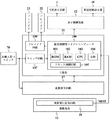
図4は、主基板11における回路構成等を示すブロック図である。主基板11には、図4に示すように、表示制御基板12と、乱数発生回路17と、から配線が接続されている。また、主基板11には、電源基板10に搭載された電源電圧監視回路18からの配線も接続されている。
FIG. 4 is a block diagram showing a circuit configuration and the like in the
始動入賞口スイッチ70は、始動入賞口である普通可変入賞球装置6への遊技球の入賞等を検出したことに基づいて、始動入賞信号(ハイレベルの信号)SSを主基板11と乱数発生回路17とに出力するものである。
The start winning
また、主基板11には、大入賞口である特別可変入賞球装置7、その他の入賞口への遊技球の入賞等を検出するための所定の入賞口スイッチからの配線も接続されている。さらに、主基板11には、普通可変入賞球装置6における可動翼片の可動制御や特別可変入賞球装置7における開成・閉成制御を行うためのソレノイド21、22への配線が接続されている。
The
主基板11は、遊技制御用マイクロコンピュータ100、スイッチ回路107と、ソレノイド回路108と、などを搭載して構成される。遊技制御用マイクロコンピュータ100は、例えば1チップマイクロコンピュータであり、ゲーム制御用のプログラム等を記憶するROM(Read Only Memory)101と、ワークメモリとして使用されるRAM(Random Access Memory)102と、制御動作を行うCPU(Central Processing Unit)103と、I/O(Input/Output)ポート104と、リセット制御回路105と、を内蔵している。
The
図5は、リセット制御回路105の一構成例を示す回路図である。図5に示すリセット制御回路105は、システムリセット延長回路311と、ユーザリセット延長回路312と、2個のAND回路313,314と、から構成されている。リセット制御回路105のシステムリセット端子XSRSTは、電源基板10に搭載された電源電圧監視回路18からの配線に接続に接続され、システムリセット信号SRSTの供給を受ける。また、リセット制御回路105のユーザリセット端子XURSTは、例えばパチンコ遊技機1内に設置されたリセットスイッチ(図示せず)に接続されるなどして、ユーザリセット信号URSTの供給を受ける。
FIG. 5 is a circuit diagram showing a configuration example of the
システムリセット延長回路311は、リセット制御回路105のシステムリセット端子XSRSTに供給されるシステムリセット信号SRSTを、所定時間延長してAND回路314の入力端子に供給する。ユーザリセット延長回路312は、AND回路313の出力端子から供給されるリセット信号を所定時間延長してAND回路314の入力端子に供給する。
The system reset
AND回路313の入力端子には、リセット制御回路105のユーザリセット端子XURSTに供給されるユーザリセット信号URSTと、遊技制御用マイクロコンピュータ100に内蔵された指定エリア外走行禁止(IAT)回路からの指定エリア外走行禁止(IAT)信号の反転信号と、遊技制御用マイクロコンピュータ100に内蔵されたウォッチドッグタイマ(WDT)からのタイムアウト信号の反転信号と、が供給される。こうした構成により、AND回路313の出力は、ユーザリセット信号URSTがハイレベルであり、指定エリア外走行禁止(IAT)信号がローレベルであり、ウォッチドッグタイマ(WDT)からのタイムアウト信号がローレベルであるときに、ハイレベルとなり、それ以外のときには、ローレベルとなる。
At the input terminal of the AND
リセット制御回路105のユーザリセット端子XURSTに供給されるユーザリセット信号URSTは、例えばパチンコ遊技機1内に設置されたリセットスイッチが押圧されるなどしてリセット操作が検出されたときに、ハイレベルからローレベルに立ち下がる。指定エリア外走行禁止(IAT)信号は、プログラム管理エリアに設定したアドレス範囲内でユーザプログラムが実行されているときにはローレベルとなっており、指定エリア外におけるユーザプログラムの実行が検出されると、ローレベルからハイレベルに立ち上がる。ウォッチドッグタイマ(WDT)からのタイムアウト信号は、予め定めたウォッチドッグタイマ(WDT)におけるタイムアウト時間が経過したときに、ローレベルからハイレベルに立ち上がる。このように、ユーザリセット信号URSTがハイレベルからローレベルに立ち下がったとき、または、指定エリア外走行禁止(IAT)信号がローレベルからハイレベルに立ち上がったとき、または、ウォッチドッグタイマ(WDT)からのタイムアウト信号がローレベルからハイレベルに立ち上がったときに、AND回路313の出力がハイレベルからローレベルに立ち下がることで、VSL電源電圧の低下とは異なる要因によるユーザリセットを発生させる。
The user reset signal URST supplied to the user reset terminal XURST of the
AND回路314の入力端子は、システムリセット延長回路311の出力端子と、ユーザリセット延長回路312の出力端子とに接続されている。従って、AND回路314の出力は、システムリセット延長回路311の出力と、ユーザリセット延長回路312の出力が共にハイレベルであるときに、ハイレベルとなり、それ以外のときには、ローレベルとなる。これにより、システムリセット及びユーザリセットのいずれかが発生したときには、リセット制御回路105から出力されるリセット制御信号RCがハイレベルからローレベルに立ち下がる。リセット制御回路105から出力されるリセット制御信号RCは、CPU103に供給される。
The input terminal of the AND
また、遊技制御用マイクロコンピュータ100は、図6に示すように、特図保留メモリ110と、大当り判定用テーブルメモリ111と、フラグメモリ112と、始動入賞口スイッチタイマメモリ113と、を備えている。
As shown in FIG. 6, the
特図保留メモリ110は、遊技球が普通可変入賞球装置6に入賞して特別図柄の可変表示(特図ゲーム)を実行するための条件(実行条件)が成立したが、従前の可変表示を実行中である等の理由のために可変表示を実際に開始するための条件(開始条件)が成立していない保留状態を記憶するためのメモリである。特図保留メモリ110は、4つのエントリを備え、各エントリには、普通可変入賞球装置6への入賞順に、保留番号と、その入賞に応じて乱数値記憶回路175から読み出した乱数値Rとが対応付けて格納される。主基板11から表示制御基板12へ特別図柄確定コマンドが送出されて特別図柄の可変表示が1回終了したり、大当り遊技状態が終了したりするごとに、最上位の情報に基づいた可変表示の開始条件が成立し、最上位の情報に基づいた可変表示が実行される。このとき、第2位以下の登録情報が1位ずつ繰り上がる。また、特別図柄の可変表示中等に遊技球が普通可変入賞球装置6に新たに入賞した場合には、その入賞に基づいて乱数値記憶回路175から読み出された乱数値Rが最上位の空エントリに登録される。
In the special
大当り判定用テーブルメモリ111は、CPU103が特図ゲームにおける表示結果を大当りとするか否かを判定するために設定される複数の大当り判定用テーブルを記憶する。具体的には、大当り判定用テーブルメモリ111は、図7(A)に示す通常時大当り判定用テーブル121と、図7(B)に示す確変時大当り判定用テーブル122と、を格納する。
The jackpot
図7(A)に示す通常時大当り判定用テーブル121と、図7(B)に示す確変時大当り判定用テーブル122と、は、可変表示装置4による特図ゲームの表示結果を大当りとするか否かを判定するためのテーブルである。各大当り判定用テーブル121及び122では、乱数値Rと特図ゲームの表示結果を示す設定データとが対応付けて格納されている。そして、確変時大当り判定用テーブル122では、通常時大当り判定用テーブル121に比べてより多くの乱数値Rが、「大当り」の表示結果と対応付けられている。すなわち、確変時大当り判定用テーブル122を用いて特図ゲームの表示結果を決定することで、通常遊技状態のときよりも大当り遊技状態となる確率が高い確率向上状態とすることができる。
Whether the normal big hit determination table 121 shown in FIG. 7 (A) and the probability variation big hit determination table 122 shown in FIG. 7 (B) use the display result of the special figure game by the
この実施の形態において、図7(A)に示す通常時大当り判定用テーブル121には、乱数発生回路17から発生する大当り判定用乱数R「0〜65335」のうち「2001〜2184」が「大当り」の表示結果と対応付けられている。一方、図7(B)に示す確変時大当り判定用テーブル121には、乱数発生回路17から発生する大当り判定用乱数R「0〜65335」のうち「2001〜3104」が「大当り」の表示結果と対応付けられている。
In this embodiment, in the normal big hit determination table 121 shown in FIG. 7A, among the big hit determination random numbers R “0 to 65335” generated from the random
図6に示すフラグメモリ112は、パチンコ遊技機1において遊技の進行を制御するために用いられる各種のフラグが設定される。例えば、フラグメモリ112には、特別図柄プロセスフラグと、普通図柄プロセスフラグと、大当り状態フラグと、入力状態フラグと、タイマ割込フラグと、などが設けられている。
In the
特別図柄プロセスフラグは、後述する特別図柄プロセス処理(図16)において、どの処理を選択・実行すべきかを指示する。普通図柄プロセスフラグは、普通図柄表示器40の表示状態を所定の順序で制御するために、所定の普通図柄プロセス処理においてどの処理を選択・実行すべきかを指示する。大当り状態フラグは、可変表示装置4による特図ゲームの表示結果が大当りとなるときにオン状態にセットされ、大当り遊技状態が終了するときにクリアされてオフ状態となる。
The special symbol process flag indicates which process should be selected / executed in the special symbol process (described later) (FIG. 16). The normal symbol process flag indicates which process should be selected and executed in a predetermined normal symbol process in order to control the display state of the
入力状態フラグは、I/Oポート104に入力される各種信号の状態等に応じて各々セットあるいはクリアさせる複数ビットからなるフラグである。タイマ割込フラグは、所定時間が経過してタイマ割込みが発生するごとにオン状態にセットされる。
The input status flag is a flag composed of a plurality of bits that are set or cleared according to the status of various signals input to the I /
始動入賞口スイッチタイマメモリ113は、始動入賞口スイッチ70から入力される始動入賞信号SSに応じて加算あるいはクリアされるタイマ値を記憶するためのものである。
The start winning port
図4に示すスイッチ回路107は、始動入賞口スイッチ70からの始動入賞信号SSを取り込んで、遊技制御用マイクロコンピュータ100に伝達する。ソレノイド回路108は、遊技制御用マイクロコンピュータ100からの指令に従って各ソレノイド21、22を駆動する。ソレノイド21は、リンク機構を介して普通可変入賞球装置6の可動翼片に連結されている。ソレノイド22は、リンク機構を介して特別可変入賞球装置7の開閉板に連結されている。
The
表示制御基板12は、主基板11とは独立して可変表示ゲームにおける画像処理のための表示制御を行うものである。表示制御基板12は、主基板11から出力される表示制御コマンドに基づいて、可変表示ゲームに用いられる画像を可変表示装置4上に表示させるとともに、普通図柄表示器40の点灯/消灯制御を行う。すなわち、表示制御基板12は、主基板11からの制御コマンドに基づいて可変表示装置4の表示動作を制御することによって、遊技の進行に関わる画像表示による演出を制御する。
The
音声制御基板13とランプ制御基板14とは、主基板11から送信される制御コマンドに基づいて、音声出力制御とランプ出力制御とを、それぞれ主基板11とは独立して実行するサブ側の制御基板である。すなわち、音声制御基板13は、主基板11からの制御コマンドに基づいてスピーカ8L、8Rによる音声出力動作を制御することによって、遊技の進行に関わる音声による演出を制御する。また、ランプ制御基板14は、主基板11からの制御コマンドに基づいて遊技効果ランプ9の点灯/消灯動作を制御することによって、遊技の進行に関わるランプの点灯、点滅あるいは消灯による演出を制御する。払出制御基板15は、遊技球の貸出や賞球等の払出制御を行うものである。情報端子基板16は、各種の遊技関連情報を外部に出力するためのものである。
The
図8は、乱数発生回路17の構成を示すブロック図である。乱数発生回路17は、図8に示すように、基準クロック信号出力回路171と、クロック信号生成回路172と、カウンタ173と、ラッチ信号出力回路174と、乱数値記憶回路175と、タイマ回路176と、から構成されている。乱数発生回路17は、大当りを発生させてパチンコ遊技機1を大当り遊技状態とするか否かを決定する大当り判定用の乱数を発生する。
FIG. 8 is a block diagram showing a configuration of the random
基準クロック信号出力回路171は、所定の周波数(例えば20MHz)の基準クロック信号S0を生成して、この生成した基準クロック信号S0をクロック信号生成回路172とタイマ回路176とに出力する。
The reference clock
クロック信号生成回路172は、D型フィリップフロップ回路などによって構成されている。クロック信号生成回路172のクロック端子CKは、基準クロック信号出力回路171の出力端子に接続され、正相出力端子Qは、カウンタ173に接続されている。また、クロック信号生成回路172の逆相出力端子(反転出力端子)Q(バー)は、その入力端子Dとラッチ信号出力回路174のクロック端子CKとに接続されている。
The clock
クロック信号生成回路172は、逆相出力端子Q(バー)から入力端子Dへとフィードバックされる信号を、基準クロック信号出力回路171からクロック端子CKへと入力される基準クロック信号S0が立ち上がるタイミングに同期させて、正相出力端子Qから出力すると共に、この正相出力端子Qから出力される信号の逆相信号(反転信号)を逆相出力端子Q(バー)から出力する。このようにして、クロック信号生成回路172は、周期が同一で位相が異なる2つのクロック信号(カウント用クロック信号S1及びラッチ用クロック信号S2)を生成して、カウント用クロック信号S1を正相出力端子Qから、ラッチ用クロック信号S2を逆相出力信号S2を逆相出力端子Q(バー)から出力することができる。
The clock
具体的には、正相出力端子Qからは、周波数10MHzのカウント用クロック信号S1が出力され、逆相出力端子Q(バー)からは、このカウント用クロック信号S1の逆相信号、即ち、カウント用クロック信号S1と同じく周波数が10MHzで、カウント用クロック信号S1とは位相がπ(=180°)だけ異なるラッチ用クロック信号S2が出力される。 Specifically, a count clock signal S1 having a frequency of 10 MHz is output from the positive phase output terminal Q, and a negative phase signal of the count clock signal S1, that is, a count is output from the negative phase output terminal Q (bar). Similarly to the clock signal S1, a latch clock signal S2 having a frequency of 10 MHz and having a phase different from that of the counting clock signal S1 by π (= 180 °) is output.
カウンタ173は、クロック信号生成回路172の正相出力端子Qから入力されるカウント用クロック信号S1の立ち上がりエッジに応答して、出力するカウント値Cを所定の初期値から所定の最終値まで循環的に更新する。
The
この実施の形態において、カウンタ173は、16ビットのバイナリカウンタであり、カウント用クロック信号S1の立ち上がりエッジが入力される毎に、カウント値Cを「0」から「65535」まで1ずつカウントアップして行く。そして、カウント値Cを「65535」までカウントアップすると、「0」に戻して、再び「65535」までカウントアップして行く。即ち、カウント値Cは、カウンタ173にカウント用クロック信号S1の立ち上がりエッジが入力される毎に、「0」→「1」→…→「65535」→「0」→…と循環的に更新される。
In this embodiment, the
ラッチ信号出力回路174は、D型フィリップフロップ回路などによって構成されている。ラッチ信号出力回路174の入力端子Dは、タイマ回路176の出力端子に接続され、クロック端子CKは、クロック信号生成回路172の逆相出力端子Q(バー)に接続されている。また、ラッチ信号出力回路174の出力端子Qは、乱数値記憶回路175に接続されている。さらに、ラッチ信号出力回路174の直接リセット(Direct Reset)端子DRは、遊技制御用マイクロコンピュータ100に内蔵されたCPU103に接続され、リセット信号RSTの供給を受ける。
The latch
ラッチ信号出力回路174は、入力端子Dから入力される始動入賞信号SSを、クロック端子CKから入力されるラッチ用クロック信号S2の立ち上がりエッジに同期させて、ラッチ信号SLを生成して出力端子Qから出力する。また、ラッチ信号出力回路174は、直接リセット端子DRから入力されるリセット信号RSTがハイレベルからローレベルに立ち下がると、クロック端子CKからの入力に非同期でクリアされる。即ち、直接リセット端子DRから入力されるリセット信号RSTがローレベルの場合、入力端子Dから始動入賞信号SSが入力されている状態で、クロック端子CKから入力されるラッチ用クロック信号S2がローレベルからハイレベルに立ち上がっても、出力端子Qから出力される信号は、常にローレベルとなる。
The latch
図8に示す乱数値記憶回路175は、16ビットレジスタであり、後述するステップS102の入賞処理において読み出される乱数値Rを記憶する。乱数値記憶回路175は、ラッチ信号出力回路174の出力端子Qから入力されるラッチ信号SLの立ち上がりエッジに応答して、カウンタ173から入力されるカウント値Cを、乱数値Rとしてラッチして記憶することにより、乱数発生回路17に始動入賞信号SSが入力される毎に、記憶する乱数値Rを順次更新する。
A random
図9は、乱数値記憶回路175の構成例を示す回路図である。乱数値記憶回路175は、図9に示すように、2個のAND回路201,203と、2個のNOT回路202,204と、16個のフィリップフロップ回路210〜225と、16個のOR回路230〜245と、から構成されている。
FIG. 9 is a circuit diagram showing a configuration example of the random
AND回路201の入力端子は、ラッチ信号出力回路174の出力端子QとNOT回路204の出力端子とに接続され、出力端子は、NOT回路202の入力端子とフィリップフロップ回路210〜225のクロック端子CK0〜CK15とに接続されている。NOT回路202の入力端子は、AND回路201の出力端子に接続され、出力端子は、AND回路203の一方の入力端子に接続されている。
The input terminal of the AND
AND回路203の入力端子は、NOT回路202の出力端子と遊技制御用マイクロコンピュータ100のI/Oポート104とに接続され、出力端子は、NOT回路204の入力端子に接続されている。NOT回路204の入力端子は、AND回路203の出力端子に接続され、出力端子は、AND回路201の一方の入力端子とOR回路230〜245の各々の一方の入力端子とに接続されている。
The input terminal of the AND
フィリップフロップ回路210〜225の入力端子D0〜D15は、カウンタ173の出力端子に接続されている。フィリップフロップ回路210〜225のクロック端子CK0〜CK15は、AND回路201の出力端子に接続され、出力端子Q0〜Q15は、OR回路230〜245の各々の他方の入力端子に接続されている。また、フィリップフロップ回路210〜225の直接リセット端子DRは、遊技制御用マイクロコンピュータ100に内蔵されたCPU103に接続され、リセット信号RSTの供給を受ける。
The input terminals D0 to D15 of the
OR回路230〜245の入力端子は、NOT回路204の出力端子とフィリップフロップ回路210〜225の出力端子の各々とに接続され、出力端子は、遊技制御用マイクロコンピュータ100のI/Oポート104に接続されている。
The input terminals of the
図10は、OR回路230〜245の出力端子と遊技制御用マイクロコンピュータ100のI/Oポート104との接続の詳細を説明するための図である。この実施の形態において、OR回路230〜245の出力端子と、I/Oポート104に含まれる大当り判定用乱数の入力ポートの各ビットと、は、図10に示すように、入れ替えて接続されている。これにより、遊技制御用マイクロコンピュータ100に入力される乱数のランダム性を高めることができる。
FIG. 10 is a diagram for explaining the details of the connection between the output terminals of the
上記構成を備える乱数値記憶回路175の動作を図11に示すタイミングチャートを参照して説明する。
The operation of the random
遊技制御用マイクロコンピュータ100から出力制御信号SC(ハイレベルの信号)が入力されていない場合に(AND回路203の一方の入力がローレベルの場合に)、ラッチ信号出力回路174の出力端子Qから入力されるラッチ信号SLがローレベルからハイレベルに立ち上がるタイミング(図11に示す例では、タイミングT1,T2,T7)に、AND回路201の入力は、共にハイレベルとなり、その出力端子から出力される信号SRは、ハイレベルとなる。そして、AND回路201から出力された信号SRは、フィリップフロップ回路210〜225のクロック端子CK0〜CK15に入力される。
When the output control signal SC (high level signal) is not input from the gaming control microcomputer 100 (when one input of the AND
フィリップフロップ回路210〜225は、クロック端子CK0〜CK15から入力される信号SRの立ち上がりエッジに応答して、カウンタ173から入力端子D0〜D15を介して入力されるカウント値CのビットデータC0〜C15を乱数値のビットデータR0〜R15としてラッチして格納し、格納した乱数値RのビットデータR0〜R15を出力端子Q0〜Q15から出力する。
The flip-
出力制御信号SCが入力されていない場合(図11に示す例では、タイミングT3までの期間、タイミングT6以降の期間)、AND回路203の一方の入力がローレベルとなるため、その出力端子から出力される信号SGは、ローレベルとなる。信号SGは、NOT回路204において反転され、OR回路230〜245の一方の入力端子には、ハイレベルの信号が入力される。
When the output control signal SC is not input (in the example shown in FIG. 11, in the period up to the timing T3, the period after the timing T6), one of the inputs of the AND
このようにOR回路230〜245の一方の入力がハイレベルとなるため、他方の入力端子に入力される信号がハイレベルであるかローレベルであるかに関わらず、即ち、入力される乱数値RのビットデータR0〜R15の値が「0」であるか「1」であるかに関わらず、OR回路230〜245から出力される信号SO0〜SO15は、全てハイレベル(「1」)となる。これにより、乱数値記憶回路175から出力される値は、常に「635535(=1111h)」となるため、乱数値記憶回路175から乱数値Rを読み出すことはできなくなる。即ち、出力制御信号SCが入力されていない場合、乱数値記憶回路175は、読出不能(ディセイブル)状態となる。
Thus, since one input of the
そして、ラッチ信号出力回路174から入力されるラッチ信号SLがローレベルのときに、遊技制御用マイクロコンピュータ100から出力制御信号SCが入力されると(図11に示す例では、タイミングT4からタイミングT6までの期間)、AND回路203の入力が共にハイレベルとなるため、その出力端子から出力される信号SGは、ハイレベルとなる。信号SGは、NOT回路204において反転され、OR回路230〜245の一方の入力端子には、ローレベルの信号が入力される。
When the output control signal SC is input from the
このようにOR回路230〜245の一方の入力がローレベルとなるため、他方の入力端子に入力される信号がハイレベルのときは、その出力端子からハイレベルの信号が出力され、ローレベルのときは、ローレベルの信号が出力される。即ち、OR回路230〜245の他方の入力端子に入力される乱数値RのビットデータR0〜R15の値は、OR回路230〜245の出力端子からそのまま(ビットデータR0〜R15の値が「1」のときは「1」が、「0」のときは「0」が、)出力される。これにより、乱数値記憶回路175からの乱数値Rの読出が可能となる。即ち、出力制御信号SCが入力されている場合、乱数値記憶回路175は、読出可能(イネイブル)状態となる。
Since one input of the
但し、遊技制御用マイクロコンピュータ100から出力制御信号SCが入力される前に、ラッチ信号出力回路174からラッチ信号SLが入力されている場合、AND回路203の一方の入力がローレベルとなるため、その後、ラッチ信号SLが入力されている状態のままの状態で、出力制御信号SCが入力されても(図11に示す例では、タイミングT3からタイミングT4の期間)、その出力端子から出力される信号SGは、ローレベルのままとなる。そして、信号SGは、NOT回路204において反転され、OR回路230〜245の一方の入力端子には、ハイレベルの信号が入力される。
However, if the latch signal SL is input from the latch
このようにOR回路230〜245の一方の入力がハイレベルとなるため、他方の入力端子に入力される信号がハイレベルであるかローレベルであるかに関わらず、OR回路230〜245から出力される信号SO0〜SO15は、全てハイレベルとなり、出力制御信号SCが入力されているにも関わらず、乱数値記憶回路175から乱数値Rを読み出すことができない状態のままとなる。即ち、ラッチ信号SLが入力されているとき、乱数値記憶回路175は、出力制御信号SCに対して受信不能状態となる。
Since one input of the
また、ラッチ信号出力回路174から入力されるラッチ信号SLがハイレベルになる前に、遊技制御用マイクロコンピュータ100から出力制御信号SCが入力されている場合、AND回路201の一方の入力がローレベルとなるため、その後、出力制御信号SCが入力されているままの状態で、入力されるラッチ信号SLがハイレベルになっても(図11に示す例では、タイミングT5)、その出力端子から出力される信号SRは、ローレベルのままとなる。このため、フィリップフロップ回路210〜225のクロック端子CK0〜CK15に入力される信号SRは、ローレベルからハイレベルに立ち上がらず、フィリップフロップ回路210〜225に格納されている乱数値RのビットデータR0〜R15は、ラッチ信号出力回路174から入力されるラッチ信号SLが立ち上がっても、更新されない。即ち、出力制御信号SCが入力されているとき、乱数値記憶回路175は、ラッチ信号SLに対して受信不能状態となる。
Further, when the output control signal SC is input from the
さらに、フィリップフロップ回路210〜225はそれぞれ、CPU103から直接リセット端子DR0〜DR15に入力されるリセット信号RSTがハイレベルからローレベルに立ち下がると、クロック端子CK0〜CK15に入力される信号SRに非同期でクリアされる。従って、CPU103から出力されたリセット信号RSTがハイレベルからローレベルに立ち下がることによって、乱数値記憶回路175のリセットが行われ、記憶されている乱数値Rが消去される。
Further, when the reset signal RST directly input from the
図8に示すタイマ回路176は、始動入賞口スイッチ70から始動入賞信号SSが入力されている時間を計測し、計測した時間が所定の時間(例えば3ms)になったとき、始動入賞信号SSをラッチ信号出力回路174に出力する。
The
この実施の形態において、タイマ回路176は、例えばアップカウンタ又はダウンカウンタによって構成され、ハイレベルの信号が入力されたことに応答して、起動する。タイマ回路176は、入力がハイレベルとなっている間、基準クロック信号出力回路171から基準クロック信号S0が入力される毎に、所定のタイマ値をアップカウント又はダウンカウントして行く。そして、アップカウント又はダウンカウントしたタイマ値が、3msに対応する値となったとき、タイマ回路176は、入力された信号を始動入賞信号SSであると判定して、始動入賞信号SSをラッチ信号出力回路174に出力する。
In this embodiment, the
図12は、乱数発生回路17の動作を説明するためのタイミングチャートである。
FIG. 12 is a timing chart for explaining the operation of the random
図12(A)に示すように、基準クロック信号出力回路171は、タイミングT10,T11,T12,…においてローレベルからハイレベルに立ち上がる周波数20MHzの基準クロック信号S0をクロック信号生成回路172のクロック端子CKに出力する。
As shown in FIG. 12A, the reference clock
クロック信号生成回路172は、逆相出力端子Q(バー)から入力端子Dへとフィードバックされるラッチ用クロック信号S2を、クロック端子CKから入力される基準クロック信号S0の立ち上がりエッジに応答して、ラッチして正相出力端子Qから出力する。これにより、正相出力端子Qからは、図12(B)に示すように、タイミングT10,T12,T14,…において、ローレベルからハイレベルへと立ち上がる周波数10MHzのカウント用クロック信号S1が出力される。
In response to the rising edge of the reference clock signal S0 input from the clock terminal CK, the clock
また、クロック信号生成回路172は、正相出力端子Qから出力するカウント用クロック信号S1を反転して逆相出力端子Q(バー)から出力する。これにより、逆相出力端子Q(バー)からは、図12(D)に示すように、タイミングT11,T13,T15,…において、ローレベルからハイレベルへと立ち上がる周波数10MHzのラッチ用クロック信号S2が出力される。
The clock
そして、カウンタ173は、図12(C)に示すように、クロック信号生成回路172の正相出力端子Qから入力されるカウント用クロック信号S1の立ち上がりエッジに応答して、カウント値Cを更新して出力する。一方、ラッチ信号出力回路174は、入力端子Dから入力される図12(E)に示す始動入賞信号SSを、クロック信号生成回路172の逆相出力端子Q(バー)からクロック端子CKへと入力されるラッチ用クロック信号S2の立ち上がりエッジに同期させて、図12(F)に示すラッチ信号SLを生成して出力端子Qから出力する。
Then, as shown in FIG. 12C, the
乱数値記憶回路175は、カウンタ173から入力端子Dへと入力されるカウント値Cを、ラッチ信号出力回路174の出力端子Qからクロック端子CKへと入力されるラッチ信号SLの立ち上がりエッジに応答して、乱数値Rとしてラッチして記憶することにより、図12(G)に示すように、記憶する乱数値Rを更新する。
The random
このようにして、乱数発生回路17は、カウント値Cの更新タイミングとカウント値Cのラッチタイミングとを確実に異ならせることができる。
In this way, the random
次に、本実施例におけるパチンコ遊技機1の動作(作用)を説明する。図13は、主基板11に搭載された遊技制御用マイクロコンピュータ100が実行する遊技制御メイン処理を示すフローチャートである。主基板11では、電源基板10からの電源電圧が供給されると、遊技制御用マイクロコンピュータ100が起動し、CPU103が、まず、図13のフローチャートに示す遊技制御メイン処理を実行する。遊技制御メイン処理を開始すると、CPU103は、割込禁止に設定した後(ステップS1)、必要な初期設定を行う(ステップS2)。この初期設定では、例えば、RAM102がクリアされる。また、遊技制御用マイクロコンピュータ100に内蔵されたCTC(カウンタ/タイマ回路)のレジスタ設定を行う。これにより、以後、所定時間(例えば、2ミリ秒ごと)ごとにCTCから割込要求信号がCPU103へ送出され、CPU103は定期的にタイマ割込処理を実行することができる。初期設定が終了すると、割込を許可した後(ステップS3)、ループ処理に入る。
Next, the operation (action) of the
図13に示す遊技制御メイン処理を実行したCPU103は、CTCからの割込要求信号を受信して割込要求を受け付けると、図14のフローチャートに示す遊技制御割込処理を実行する。 CPU103 which performed the game control main process shown in FIG. 13 will perform the game control interruption process shown in the flowchart of FIG. 14, if the interruption request signal from CTC is received and an interruption request | requirement is received.
遊技制御割込処理を開始すると、CPU103は、まず、所定のリセット処理を実行する(ステップS11)。リセット処理では、システムリセットやユーザリセットの発生を検知したことに応じて、主基板11により制御される各電気部品を適切な動作停止状態とするための各種設定が行われる。
When the game control interrupt process is started, the
リセット処理を実行した後には、所定のスイッチ処理を実行する(ステップS12)。スイッチ処理では、スイッチ回路107を介して始動入賞口スイッチ70から入力される始動入賞信号SSがオン状態となっているか否かを判別する。始動入賞信号SSがオン状態である場合には、タイマ値を「1」加算して始動入賞口スイッチタイマメモリ113に格納する。一方、始動入賞信号SSがオフ状態である場合には、タイマ値をクリアする。
After executing the reset process, a predetermined switch process is executed (step S12). In the switch process, it is determined whether or not the start winning signal SS input from the start winning
続いて、所定のエラー処理を実行することにより、パチンコ遊技機1の異常診断を行い、その診断結果に応じて必要ならば警告を発生可能とする(ステップS13)。この後、所定の判定用乱数を更新する判定用乱数更新処理(ステップS14)と、所定の表示用乱数を更新する表示用乱数更新処理(ステップS15)と、を順次実行する。
Subsequently, by executing predetermined error processing, abnormality diagnosis of the
次に、CPU103は、特別図柄プロセス処理を実行する(ステップS16)。特別図柄プロセス処理では、遊技状態に応じてパチンコ遊技機1を所定の順序で制御するために、フラグメモリ112に設けられた特別図柄プロセスフラグに従って該当する処理が選択されて実行される。特別図柄プロセス処理に続いて、CPU103は、普通図柄プロセス処理を実行する(ステップS17)。普通図柄プロセス処理では、普通図柄表示器40を所定の順序で制御するために、フラグメモリ112に設けられた普通図柄プロセスフラグに従って該当する処理が選択されて実行される。
Next, the
さらに、CPU103は、所定のコマンド制御処理を実行することにより、主基板11から表示制御基板12等のサブ側の制御基板に対して制御コマンドを送出し、遊技状態に合わせた演出動作等の動作制御を指示する(ステップS18)。例えば、CPU103が所定のコマンド送信テーブルに設定された制御データに基づいてI/Oポート104からの信号出力動作を制御することなどにより、表示制御基板12等のサブ側の制御基板に対して、遊技の進行を制御する制御信号を送信させる。このコマンド制御処理により主基板11から送出された表示制御コマンドを表示制御基板12のCPUが受け取り、その表示制御コマンドに従って可変表示装置4の表示制御や普通図柄表示器40の点灯制御などが行われる。
Furthermore, the
また、CPU103は、所定の情報出力処理を実行することにより、各種出力データの格納領域の内容をI/Oポート104に含まれる各出力ポートに出力する(ステップS19)。この情報出力処理では、主基板11から情報端子基板16に、大当り情報、始動情報、確率変動情報などをホール管理用コンピュータに対して出力する指令の送出も行われる。
Further, the
続いて、CPU103は、所定のソレノイド出力処理を実行することにより、所定の条件が成立したときに普通可変入賞球装置6における可動翼片の可動制御や特別可変入賞球装置7における開閉板の開閉駆動を行う(ステップS20)。この後、所定の賞球処理を実行することにより、始動入賞口スイッチ70から入力された始動入賞信号SSに基づく賞球数の設定などを行い、払出制御基板15に対して払出制御コマンドを出力可能とする(ステップS21)。
Subsequently, the
図15は、ステップS11にて実行されるリセット処理の一例を示すフローチャートである。リセット処理を開始すると、CPU103は、まず、パチンコ遊技機1にてシステムリセット及びユーザリセットのうちでいずれかのリセットが発生したか否かを、リセット制御回路105から入力されるリセット制御信号RCにおける信号レベルをチェックすることにより、判別する(ステップS51)。ステップS51において、CPU103は、リセット制御回路105から供給されているリセット信号がハイレベルとなっているときには、リセットが発生していないと判断して(ステップS51;No)、そのままリセット処理を終了する。
FIG. 15 is a flowchart illustrating an example of the reset process executed in step S11. When the reset process is started, the
これに対して、リセット制御回路105からのリセット信号がハイレベルからローレベルへと立ち下がったときには、リセットが発生したと判断して(ステップS51;Yes)、例えばバックアップRAM領域のデータについてパリティデータを生成してRAM102に格納したり、RAM102をアクセス禁止状態にしたりするなど、リセットの発生に応じた所定のリセット用設定処理を実行する(ステップS52)。この際、CPU103は、乱数発生回路17に搭載されたラッチ信号出力回路174及び乱数値記憶回路175に対して、ハイレベルからローレベルへと立ち下がるリセット信号RSTを送出する(ステップS53)。このリセット信号RSTに応答して、乱数発生回路17では、ラッチ信号出力回路174及び乱数値記憶回路175のリセットが行われる。
On the other hand, when the reset signal from the
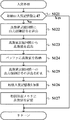
図16は、ステップS16にて実行される特別図柄プロセス処理を示すフローチャートである。特別図柄プロセス処理を開始すると、CPU103は、まず、遊技球が普通可変入賞球装置6に入賞したか否かを、始動入賞口スイッチタイマメモリ113に記憶されているタイマ値をチェックすることにより、判別する(ステップS101)。ステップS101において、CPU103は、始動入賞口スイッチタイマメモリ113に記憶されているタイマ値をロードし、ロードしたタイマ値を所定のスイッチオン判定値(例えば「2」)と比較する。ここで、スイッチオン判定値は、タイマ割込処理の実行回数(例えば「2」)に対応して予め定められている。これにより、CPU103は、所定回(例えば2回)のタイマ割込処理が実行されている間(例えば4ms)、始動入賞口スイッチ70から始動入賞信号SSが継続して入力されたが否かを判別することができる。
FIG. 16 is a flowchart showing the special symbol process executed in step S16. When the special symbol process is started, the
そして、この比較結果に基づいて、CPU103は、タイマ値がスイッチオン判定値「2」以上であるか否かを判別する。タイマ値がスイッチオン判定値「2」以上である場合には、遊技球が入賞しているものと判別して(ステップS101;Yes)、入賞処理を実行する(ステップS102)と共に、タイマ値をクリアする。一方、タイマ値がスイッチオン判定値「2」未満である場合には、遊技球が入賞していないものと判別して(ステップS101;No)、入賞処理をスキップする。
Based on the comparison result, the
図17は、ステップS102の入賞処理を示すフローチャートである。この入賞処理において、CPU103は、まず、特図保留メモリ110が記憶している始動入賞記憶数が最大値の「4」であるか否かを判別する(ステップS121)。ここで、特図保留メモリ110において、始動入賞記憶番号「4」に対応した乱数値Rが記憶されている場合には、始動入賞記憶数が「4」であると判別される。
FIG. 17 is a flowchart showing the winning process in step S102. In this winning process, the
始動入賞記憶数が「4」であるときには(ステップS121;Yes)、今回の入賞による始動検出は無効として、そのまま入賞処理が終了する。一方、始動入賞記憶数が「4」未満であるときには(ステップS121;No)、乱数値記憶回路175に出力制御信号SCを送出して、乱数値記憶回路175を読出可能(イネイブル)状態に制御する(ステップS122)。
When the start winning memory number is “4” (step S121; Yes), the start detection by the current winning is invalidated, and the winning process is ended as it is. On the other hand, when the start winning memory number is less than “4” (step S121; No), an output control signal SC is sent to the random
続いて、CPU103は、乱数値記憶回路175から乱数値Rを読み出し(ステップS123)、この読み出した乱数値Rを、例えばRAM102に設けられた所定のバッファ領域に格納した後(ステップS124)、乱数値記憶回路175への出力制御信号SCの送出を停止して、乱数値記憶回路175を読出不能(ディセイブル)状態に制御する(ステップS125)。そして、CPU103は、始動入賞記憶数を「1」加算し(ステップS126)、所定のバッファ領域に格納した乱数値Rを特図保留メモリ110の空エントリの先頭にセットする(ステップS127)。
Subsequently, the
この後、CPU103は、フラグメモリ112に格納されている特別図柄プロセスフラグの値に基づいて、図16に示すステップS110〜S118の9個の処理のいずれかを選択する。以下に、ステップS110〜S118の各処理について説明する。
Thereafter, the
ステップS110の特別図柄通常処理は、特別図柄プロセスフラグの値が初期値「0」のときに実行される処理である。この処理において、CPU103は、特図保留メモリ110が記憶している保留記憶数が「0」であるか否かを判別する。ここで、特図保留メモリ110において、保留番号「1」に対応した乱数値R等の各種データが記憶されていない場合には、保留記憶数が「0」であると判別される。保留記憶数が「0」であれば、表示制御基板12を介して可変表示装置4上にデモンストレーション画面を表示するなどして、特別図柄通常処理を終了する。一方、保留記憶数が「0」ではないと判別すると、特別図柄プロセスフラグの値を大当り判定処理に対応した値である「1」に更新する。
The special symbol normal process of step S110 is a process executed when the value of the special symbol process flag is the initial value “0”. In this process, the
ステップS111の大当り判定処理は、特別図柄プロセスフラグの値が「1」のときに実行される処理である。この処理において、CPU103は、図18に示すように、まず、特図保留メモリ110から保留番号「1」に対応して格納されている乱数値Rを読み出す(ステップS131)。この際、保留記憶数を「1」減算し、且つ、特図保留メモリ110の第2〜第4エントリ(保留番号「2」〜「4」)に格納された乱数値Rを1エントリずつ上位にシフトする(ステップS132)。
The jackpot determination process in step S111 is a process executed when the value of the special symbol process flag is “1”. In this process, as shown in FIG. 18, the
続いて、CPU103は、確率向上状態(確変中)であるか否かを判別し(ステップS133)、確変中ではなければ(ステップS133;No)、通常遊技状態であると判断し、特図ゲームの表示結果を大当りとするか否かを判定するためのテーブルとして、図7(A)に示すような通常時大当り判定用テーブル121を設定する(ステップS134)。これに対して、確変中であれば(ステップS133;Yes)、図7(B)に示すような確変時大当り判定用テーブル122を設定する(ステップS135)。
Subsequently, the
CPU103は、ステップS131にて読み出した乱数値Rに基づき、ステップS134又はS135にて設定した大当り判定用テーブル121又は122を用いて特図ゲームの表示結果を大当りとするか否かを判定する(ステップS136)。そして、大当りとすることに決定した場合には(ステップS136;Yes)、フラグメモリ112に設けられた大当り状態フラグをオン状態にセットし(ステップS137)、ハズレとすることに決定した場合には(ステップS136;No)、大当り状態フラグをクリアしてオフ状態とする(ステップS138)。この後、特別図柄プロセスフラグの値を確定図柄決定処理に対応した値である「2」に更新する(ステップS139)。
Based on the random number value R read out in step S131, the
図16に示すステップS112の確定図柄決定処理は、特別図柄プロセスフラグの値が「2」のときに実行される処理である。この処理において、CPU103は、フラグメモリ112に設けられた大当り状態フラグがオンとなっているか否かを判別するとともに、所定のリーチ判定用乱数を抽出した結果等に基づいて、リーチとするか否かを判別する。これらの判別結果に従って、可変表示装置4による特図ゲームにおける最終的な確定図柄が設定される。その後、特別図柄プロセスフラグの値を可変表示パターン設定処理に対応した値である「3」に更新する。
The confirmed symbol determination process in step S112 shown in FIG. 16 is a process executed when the value of the special symbol process flag is “2”. In this process, the
ステップS113の可変表示パターン設定処理は、特別図柄プロセスフラグの値が「3」のときに実行される処理である。この処理において、CPU103は、まず、フラグメモリ112に設けられた大当り状態フラグがオンとなっているか否かを判別するとともに、上記ステップS112の確定図柄決定処理にてリーチとすることが決定されたか否かを判別し、これらの判別結果に従って、所定の可変表示パターンテーブルを設定する。そして、所定の可変表示パターン決定用乱数を抽出した結果等に基づいて、設定した可変表示パターンテーブルのうちから、今回の特図ゲームで使用する可変表示パターンを決定する。こうして可変表示パターンを決定した後、CPU103は、特別図柄プロセスフラグの値を可変表示指令処理に対応した値である「4」に更新する。
The variable display pattern setting process of step S113 is a process executed when the value of the special symbol process flag is “3”. In this process, the
ステップS114の可変表示指令処理は、特別図柄プロセスフラグの値が「4」のときに実行される処理である。この処理において、CPU103は、可変表示装置4において特別図柄の全図柄が可変表示を開始するように制御する。具体的には、上述したステップS112の確定図柄決定処理にて決定した特別図柄の確定図柄に対応する制御データや、ステップS113の可変表示パターン設定処理にて決定した可変表示パターンに対応する制御データを、所定のコマンド送信テーブルに設定するなどして、可変表示開始コマンドと左・中・右の図柄指定コマンドを表示制御基板12に対して送出可能に設定する。そして、可変表示パターンに対応する総可変表示時間を所定の可変表示時間タイマに設定し、可変表示開始コマンドが送信されるとともにカウントダウンを開始する。この後、所定の可変表示時間タイマがタイムアウトすると、特別図柄プロセスフラグの値を可変表示停止時処理に対応した値である「5」に更新する。
The variable display command process of step S114 is a process executed when the value of the special symbol process flag is “4”. In this process, the
ステップS115の可変表示停止時処理は、特別図柄プロセスフラグの値が「5」のときに実行される処理である。この処理において、CPU103は、主基板11から表示制御基板12に対して特別図柄確定コマンドを送出するための設定を行う。具体的には、特別図柄確定コマンドに対応する制御データを、所定のコマンド送信テーブルに設定するなどして、特別図柄確定コマンドを表示制御基板12に対して送出可能に設定する。また、パチンコ遊技機1が確率向上状態となっているときには、確率向上状態から通常遊技状態に戻すか否かを判定し、戻すと判定すると、パチンコ遊技機1における遊技状態を確率向上状態から通常遊技状態に移行させる。そして、可変表示の表示結果が大当りになるときは、特別図柄プロセスフラグの値を大入賞口開放前処理に対応した値である「6」に更新し、ハズレとなるときには、特別図柄プロセスフラグの値を「0」に更新する。
The variable display stop process in step S115 is a process executed when the value of the special symbol process flag is “5”. In this process, the
ステップS116の大入賞口開放前処理は、特別図柄プロセスフラグの値が「6」のときに実行される処理である。この処理において、CPU103は、大入賞口としての特別可変入賞球装置7を開放する制御を開始するための設定を行う。そして、特別可変入賞球装置7を開放する制御を開始するとともに、特別図柄プロセスフラグの値を大入賞口開放中処理に対応した値である「7」に更新する。
The pre-opening process for the special winning opening in step S116 is a process executed when the value of the special symbol process flag is “6”. In this process, the
ステップS117の大入賞口開放中処理は、特別図柄プロセスフラグの値が「7」のときに実行される処理である。この処理において、CPU103は、開成された特別可変入賞球装置7への遊技球の入賞検出、賞球の払出指令、開成時間の計測、及び開成サイクルのラウンド数表示のための表示制御コマンド設定等を行う。そして、例えば、1回の大当りについて、特別可変入賞球装置7の開成回数をカウントし、開成回数が例えば16回に達していれば、特定遊技状態(大当り遊技状態)を終了する条件が終了したとして特別図柄プロセスフラグの値を大当り終了処理に対応した値である「8」に更新する。一方、開成回数が16回に達していなければ、特別可変入賞球装置7を一旦閉成した後、所定時間が経過するのを待って再度開成する。
The special winning opening opening process in step S117 is a process executed when the value of the special symbol process flag is “7”. In this process, the
ステップS118の大当り終了処理は、特別図柄プロセスフラグの値が「8」のときに実行される処理である。この処理において、CPU103は、表示制御基板12に対して所定の大当り終了コマンドを送出するための設定を行うなどして、大当り遊技状態を終了させる。また、CPU103は、フラグメモリ112に設けられた大当り状態フラグをクリアしてオフ状態とする。そして、特別図柄プロセスフラグの値を「0」に更新する。
The jackpot end process in step S118 is a process executed when the value of the special symbol process flag is “8”. In this process, the
以上説明したように、この実施の形態によれば、クロック信号生成回路172は、逆相出力端子Q(バー)から入力端子Dへとフィードバックされるラッチ用クロック信号S2を、クロック端子CKから入力される基準クロック信号S0の立ち上がりエッジに応答して、ラッチすることにより、カウント用クロック信号S1を生成して正相出力端子Qから出力する。また、クロック信号生成回路172は、生成したカウント用クロック信号S1を反転してラッチ用クロック信号S2を逆相出力端子Q(バー)から出力する。
As described above, according to this embodiment, the clock
カウンタ173は、クロック信号生成回路172の正相出力端子Qから入力されるカウント用クロック信号S1がローレベルからハイレベルへと立ち上がるタイミングT10,T12,T14,…において、カウント値Cを順次更新して行く。
The
そして、始動入賞口である普通可変入賞球装置6へ遊技球が入賞すると、始動入賞口スイッチ70は、始動入賞信号SSを主基板11と乱数発生回路17とに対して送出し、乱数発生回路17に対して送出された始動入賞信号SSは、タイマ回路176を介してラッチ信号出力回路174の入力端子Dへと入力される。ラッチ信号出力回路174は、この入力端子Dに入力される始動入賞信号SSを、クロック信号生成回路172の逆相出力端子Q(バー)からクロック端子CKへと入力されるラッチ用クロック信号S2がローレベルからハイレベルへと立ち上がるタイミングT11,T13,T15,…において、ラッチ信号SLとして出力端子Qから出力する。
When a game ball wins the normal variable winning ball apparatus 6 which is a starting winning opening, the starting winning
乱数値記憶回路175は、カウンタ173から入力端子Dへと入力されるカウント値Cを、ラッチ信号出力回路174の出力端子Qからクロック端子CKへと入力されるラッチ信号SLの立ち上がりエッジに応答して、乱数値Rとしてラッチして記憶する。
The random
このようにして、乱数発生回路17は、カウンタ173によるカウント値Cの更新タイミングと、ラッチ信号出力回路174によるラッチ信号SLの出力タイミング(ラッチタイミング)と、を確実に異ならせることができる。また、乱数発生回路17は、基準クロック信号S0を反転させることなく、カウント値Cの更新とラッチ信号SLの出力とを行っているため、基準クロック信号S0の立ち下がりが緩やかな場合でも、更新タイミングやラッチタイミングを安定させることができる。この結果、パチンコ遊技機1は、乱数値Rの取得を確実且つ安定的に行うことができる。
In this way, the random
一方、主基板11の側では、CPU103は、始動入賞口スイッチ70から始動入賞信号SSが、所定回(例えば2回)のタイマ割込処理が実行されている間(例えば4ms)、継続して入力されたことを検出すると、入賞処理を実行する。
On the other hand, on the
この入賞処理において、CPU103は、乱数値記憶回路175に出力制御信号SCを送出して乱数値記憶回路175を読出可能(イネイブル)状態に制御した後、乱数値記憶回路175から乱数値Rを読み出す。そして、CPU103は、乱数値記憶回路175への出力制御信号SCの送出を停止して乱数値記憶回路175を読出不能(ディセイブル)状態に制御した後、読み出した乱数値Rが所定の判定値「2001〜2184」などと一致するか否かを判定することにより、可変表示装置4による特図ゲームの表示結果を大当り遊技状態とするか否かを決定する。
In this winning process, the
このように、CPU103が乱数値Rを読み出すときのみ、乱数値記憶回路175を読出可能状態に制御することにより、パチンコ遊技機1は、乱数値の取得をより一層、確実且つ安定的に行うことができる。また、CPU103は、始動入賞口である普通可変入賞球装置6へ遊技球が入賞したときのみ、乱数値記憶回路175から乱数値Rを読み出すため、パチンコ遊技機1は、無駄な処理を省略することができる。
In this way, the
また、電源基板10が備える電源電圧監視回路18には、VSL電源電圧が所定値(例えば+22V)以下になると電源断信号をシステムリセット信号SRSTとして出力する電源監視用IC301が搭載されている。電源監視用IC301からのシステムリセット信号SRSTは、主基板11の遊技制御用マイクロコンピュータ100に入力される。このシステムリセット信号SRSTがハイレベルからローレベルへと立ち下がることに応答して、遊技制御用マイクロコンピュータ100に搭載されたリセット制御回路105により生成されるリセット制御信号RCが、ハイレベルからローレベルへと立ち下がる。遊技制御用マイクロコンピュータ100のCPU103は、リセット制御信号RCがハイレベルからローレベルへと立ち下がったときに、乱数発生回路17のラッチ信号出力回路174及び乱数値記憶回路175に対してリセット信号RSTを出力する。
The power supply
ここで、CPU103からのリセット信号RSTを伝送する配線は、ラッチ信号出力回路174の直接リセット端子DR、及び乱数値記憶回路175が備えるフィリップフロップ回路210〜225の直接リセット端子DR0〜DR15に接続されており、リセット信号RSTの信号レベルがハイレベルからローレベルへと立ち下がることによって、ラッチ信号出力回路174及び乱数値記憶回路175のリセットが行われる。
Here, the wiring for transmitting the reset signal RST from the
このように、システムリセットやユーザリセットが発生したときにラッチ信号出力回路174のリセットを行うようにしたことで、例えば電源電圧の低下に起因するノイズの影響等によってラッチ信号出力回路174から乱数値記憶回路175に誤ってラッチ信号SLが出力されることにより乱数値記憶回路175が誤ったタイミングでカウンタ173から入力端子Dへと入力されるカウント値Cを乱数値Rとしてラッチして記憶するのを防止し、誤って乱数値記憶回路175に記憶された乱数値Rが読み出されるなどの誤動作を防ぐことができる。
As described above, since the latch
また、システムリセットやユーザリセットが発生したときに乱数値記憶回路175のリセットを行うようにしたことで、例えばノイズの影響等によって乱数値記憶回路175が誤ってカウンタ173から入力端子Dへと入力されるカウント値Cを乱数値Rとしてラッチして記憶した場合でも、記憶されている乱数値Rを消去することができるので、誤って乱数値記憶回路175に記憶された乱数値Rが読み出されるなどの誤動作を防ぐことができる。
Further, since the random
なお、乱数発生回路17は、始動入賞口スイッチ70から出力された始動入賞信号SSをラッチ信号出力回路174に直接入力するのではなく、一旦タイマ回路176に入力して、始動入賞信号SSの入力時間を計測し、計測した時間が予め設定された時間(3ms)になったとき、始動入賞信号SSをラッチ信号出力回路174に入力する。このため、パチンコ遊技機1は、ラッチ信号出力回路174がノイズの影響等により誤って乱数値記憶回路175にラッチ信号SLを出力することを防止することができる。また、タイマ回路176には、2回のタイマ割込処理の実行間「4ms」よりも短い「3ms」が設定されているため、CPU103が乱数値記憶回路175から読み出した乱数値Rが前回の入賞時に読み出した乱数値Rの値と同じ値となることを防止することができる。
The random
また、乱数値記憶回路175は、ラッチ信号出力回路174からラッチ信号SLが入力されているとき、遊技制御用マイクロコンピュータ100から入力される出力制御信号(ハイレベルの信号)SCをローレベルの信号に変換することにより、出力制御信号SCに対して受信不能状態に制御する。これにより、乱数値記憶回路175に記憶されている乱数値Rが更新されているときに、CPU103により乱数値記憶回路175から乱数値Rが読み出されることを防止することができるため、パチンコ遊技機1は、乱数値Rの更新を確実且つ安定的に行うことができる。
In addition, when the latch signal SL is input from the latch
さらに、乱数値記憶回路175は、遊技制御用マイクロコンピュータ100から出力制御信号SCが入力されているとき、ラッチ信号出力回路174から入力されるラッチ信号(ハイレベルの信号)SLをローレベルの信号に変換することにより、ラッチ信号SLに対して受信不能状態に制御する。これにより、遊技制御用マイクロコンピュータ100が乱数値記憶回路175から乱数値Rを読み出しているときに、乱数値記憶回路175に記憶されている乱数値Rが更新されることを防止することができるため、パチンコ遊技機1は、乱数値Rの取得を確実且つ安定的に行うことができる。
Furthermore, when the output control signal SC is input from the
なお、この発明は、上記の実施の形態に限られず、種々の変形、応用が可能である。以下、この発明に適用可能な上記の実施の形態の変形態様について説明する。 In addition, this invention is not restricted to said embodiment, A various deformation | transformation and application are possible. Hereinafter, modifications of the above-described embodiment applicable to the present invention will be described.
上記実施の形態において、始動入賞口スイッチ70は、始動入賞口である普通可変入賞球装置6への遊技球の入賞等を検出したことに基づいて、始動入賞信号SSを主基板11と乱数発生回路17とに出力し、そして、乱数発生回路17は、タイマ回路176において、始動入賞口スイッチ70から始動入賞信号SSが入力されている時間を計測し、計測した時間が所定の時間(例えば3ms)になったとき、始動入賞信号SSをラッチ信号出力回路174に出力していた。
In the above-described embodiment, the start winning
しかしながら、本発明は、これに限定されず、始動入賞口スイッチ70は、始動入賞信号SSを主基板11に対してのみ出力し、主基板11に搭載されているCPU103は、所定回(例えば2回)のタイマ割込処理が実行されている間(例えば4ms間)、始動入賞口スイッチ70から始動入賞信号SSが継続して入力されたことに基づいて、ラッチ用始動入賞信号SNをラッチ信号出力回路174に送出してもよい。
However, the present invention is not limited to this, and the start winning
このような変形例に係る遊技機について、以下図面を参照して説明する。図19は、この変形例に係る主基板11における回路構成等を示すブロック図であり、図20は、この変形例に係る乱数発生回路27の構成を示すブロック図である。なお、乱数発生回路27において、上記実施の形態に係る乱数発生回路17と同一の構成については、同一の符号を付し、必要に応じてその説明を省略する。
A gaming machine according to such a modification will be described below with reference to the drawings. FIG. 19 is a block diagram showing a circuit configuration and the like in the
乱数発生回路27は、図20に示すように、基準クロック信号出力回路171と、クロック信号生成回路172と、カウンタ173と、ラッチ信号出力回路174と、乱数値記憶回路175と、から構成されている。
As shown in FIG. 20, the random
ラッチ信号出力回路174の入力端子Dは、I/Oポート104に接続され、クロック端子CKは、クロック信号生成回路172の逆相出力端子Q(バー)に接続されている。また、ラッチ信号出力回路174の出力端子Qは、乱数値記憶回路175に接続されている。さらに、ラッチ信号出力回路174の直接リセット端子DRは、遊技制御用マイクロコンピュータ100に内蔵されたCPU103に接続され、リセット信号RSTの供給を受ける。ラッチ信号出力回路174は、入力端子Dから入力されるラッチ用始動入賞信号SNを、クロック端子CKから入力されるラッチ用クロック信号S2の立ち上がりエッジに同期させて、ラッチ信号SLを生成して出力端子Qから出力する。また、ラッチ信号出力回路174は、直接リセット端子DRから入力されるリセット信号RSTがハイレベルからローレベルに立ち下がると、クロック端子CKからの入力に非同期でクリアされる。
The input terminal D of the latch
図21は、乱数発生回路27の動作を説明するためのタイミングチャートである。
FIG. 21 is a timing chart for explaining the operation of the random
図21(A)に示すように、基準クロック信号出力回路171は、タイミングT10,T11,T12,…においてローレベルからハイレベルに立ち上がる周波数20MHzの基準クロック信号S0をクロック信号生成回路172のクロック端子CKに出力する。
As shown in FIG. 21A, the reference clock
クロック信号生成回路172は、逆相出力端子Q(バー)から入力端子Dへとフィードバックされるラッチ用クロック信号S2を、クロック端子CKから入力される基準クロック信号S0の立ち上がりエッジに応答して、ラッチして正相出力端子Qから出力する。これにより、正相出力端子Qからは、図21(B)に示すように、タイミングT10,T12,T14,…において、ローレベルからハイレベルへと立ち上がる周波数10MHzのカウント用クロック信号S1が出力される。
In response to the rising edge of the reference clock signal S0 input from the clock terminal CK, the clock
また、クロック信号生成回路172は、正相出力端子Qから出力するカウント用クロック信号S1を反転して逆相出力端子Q(バー)から出力する。これにより、逆相出力端子Q(バー)からは、図21(D)に示すように、タイミングT11,T13,T15,…において、ローレベルからハイレベルへと立ち上がる周波数10MHzのラッチ用クロック信号S2が出力される。
The clock
そして、カウンタ173は、図21(C)に示すように、クロック信号生成回路172の正相出力端子Qから入力されるカウント用クロック信号S1の立ち上がりエッジに応答して、カウント値Cを更新して出力する。一方、ラッチ信号出力回路174は、入力端子Dから入力される図21(E)に示すラッチ用始動入賞信号SNを、クロック信号生成回路172の逆相出力端子Q(バー)からクロック端子CKへと入力されるラッチ用クロック信号S2の立ち上がりエッジに同期させて、図21(F)に示すラッチ信号SLを生成して出力端子Qから出力する。
Then, as shown in FIG. 21C, the
乱数値記憶回路175は、カウンタ173から入力端子Dへと入力されるカウント値Cを、ラッチ信号出力回路174の出力端子Qからクロック端子CKへと入力されるラッチ信号SLの立ち上がりエッジに応答して、乱数値Rとしてラッチして記憶することにより、図21(G)に示すように、記憶する乱数値Rを更新する。
The random
このようにして、乱数発生回路27は、カウント値Cの更新タイミングとカウント値Cのラッチタイミングとを確実に異ならせることができる。
In this way, the random
加えて、CPU103からのリセット信号RSTは、ラッチ信号出力回路174の他に、乱数値記憶回路175にも供給されており、リセット制御信号RCがハイレベルからローレベルに立ち下がることによって、乱数値記憶回路175のリセットが行われ、乱数値記憶回路175に記憶されている乱数値Rが消去される。
In addition, the reset signal RST from the
また、この変形例において、図6に示すフラグメモリ112には、上述したフラグに加えて、乱数値読出フラグが設けられている。この乱数値読出フラグは、ラッチ用始動入賞信号SNがラッチ信号出力回路174へ送出されたときにオン状態にセットされ、乱数値記憶回路175から乱数値Rが読み出されるとクリアされてオフ状態となる。
In this modification, the
図22は、この変形例において、ステップS16にて実行される特別図柄プロセス処理を示すフローチャートである。特別図柄プロセス処理を開始すると、CPU103は、まず、フラグメモリ112に設けられた乱数値読出フラグがオンとなっているか否かを判別する(ステップS201)。
FIG. 22 is a flowchart showing the special symbol process executed in step S16 in this modification. When the special symbol process is started, the
乱数値読出フラグがオフであるときには(ステップS201;No)、遊技球が普通可変入賞球装置6に入賞したか否かを、始動入賞口スイッチタイマメモリ113に記憶されているタイマ値をチェックすることにより、判別する(ステップS202)。ステップS202において、CPU103は、始動入賞口スイッチタイマメモリ113に記憶されているタイマ値をロードし、ロードしたタイマ値を所定のスイッチオン判定値(例えば「2」)と比較する。ここで、スイッチオン判定値は、タイマ割込処理の実行回数(例えば「2」)に対応して予め定められている。これにより、CPU103は、所定回(例えば2回)のタイマ割込処理が実行されている間(例えば4ms間)、始動入賞口スイッチ70から始動入賞信号SSが継続して入力されたが否かを判別することができる。
When the random number read flag is off (step S201; No), the timer value stored in the start winning mouth
そして、この比較結果に基づいて、CPU103は、タイマ値がスイッチオン判定値「2」以上であるか否かを判別する。タイマ値がスイッチオン判定値「2」以上である場合には、遊技球が入賞しているものと判別して(ステップS202;Yes)、入賞処理を実行する(ステップS203)と共に、タイマ値をクリアする。一方、タイマ値がスイッチオン判定値「2」未満である場合には、遊技球が入賞していないものと判別して(ステップS202;No)、入賞処理をスキップする。
Based on the comparison result, the
図23は、ステップS203の入賞処理を示すフローチャートである。この入賞処理において、CPU103は、まず、特図保留メモリ110が記憶している始動入賞記憶数が最大値の「4」であるか否かを判別する(ステップS221)。ここで、特図保留メモリ110において、始動入賞記憶番号「4」に対応した乱数値Rが記憶されている場合には、始動入賞記憶数が「4」であると判別される。
FIG. 23 is a flowchart showing the winning process in step S203. In this winning process, the
始動入賞記憶数が「4」であるときには(ステップS221;Yes)、今回の入賞による始動検出は無効として、そのまま入賞処理が終了する。一方、始動入賞記憶数が「4」未満であるときには(ステップS221;No)、ラッチ用始動入賞信号SNがラッチ信号出力回路174に送出し(ステップS222)、乱数値読出フラグをオン状態にセットする(ステップS223)。 When the start winning memory number is “4” (step S221; Yes), the start detection by the current winning is invalidated, and the winning process is ended as it is. On the other hand, when the start winning memory number is less than “4” (step S221; No), the latch start winning signal SN is sent to the latch signal output circuit 174 (step S222), and the random number read flag is set to the on state. (Step S223).
また、ステップS201にて乱数値読出フラグがオンであるときには(ステップS201;Yes)、乱数値読出処理を実行する(ステップS204)。 When the random value read flag is on in step S201 (step S201; Yes), random number read processing is executed (step S204).
図24は、ステップS204の乱数値読出処理を示すフローチャートである。この乱数値読出処理において、CPU103は、まず、乱数値記憶回路175に出力制御信号SCを送出して、乱数値記憶回路175を読出可能(イネイブル)状態に制御する(ステップS231)。続いて、CPU103は、乱数値記憶回路175から乱数値Rを読み出し(ステップS232)、この読み出した乱数値Rを、例えばRAM102に設けられた所定のバッファ領域に格納した後(ステップS233)、乱数値記憶回路175への出力制御信号SCの送出を停止して、乱数値記憶回路175を読出不能(ディセイブル)状態に制御する(ステップS234)。
FIG. 24 is a flowchart showing the random number value reading process in step S204. In this random value reading process, the
そして、CPU103は、始動入賞記憶数を「1」加算し(ステップS235)、所定のバッファ領域に格納した乱数値Rを特図保留メモリ110の空エントリの先頭にセットする(ステップS236)。この後、CPU103は、乱数値読出フラグをクリアしてオフ状態とする(ステップS237)。
Then, the
以上説明したように、この変形例によれば、クロック信号生成回路172は、逆相出力端子Q(バー)から入力端子Dへとフィードバックされるラッチ用クロック信号S2を、クロック端子CKから入力される基準クロック信号S0の立ち上がりエッジに応答して、ラッチすることにより、カウント用クロック信号S1を生成して正相出力端子Qから出力する。また、クロック信号生成回路172は、生成したカウント用クロック信号S1を反転してラッチ用クロック信号S2を逆相出力端子Q(バー)から出力する。
As described above, according to this modification, the clock
カウンタ173は、クロック信号生成回路172の正相出力端子Qから入力されるカウント用クロック信号S1がローレベルからハイレベルへと立ち上がるタイミングT10,T12,T14,…において、カウント値Cを順次更新して行く。
The
そして、始動入賞口である普通可変入賞球装置6へ遊技球が入賞すると、始動入賞口スイッチ70は、始動入賞信号SSを主基板11に対してのみ送出する。主基板11のCPU103は、始動入賞口スイッチ70から始動入賞信号SSが、所定回(例えば2回)のタイマ割込処理が実行されている間(例えば4ms)、継続して入力されたことに基づいて、普通可変入賞球装置6へ遊技球が入賞したものと判別して、乱数発生回路27に対してラッチ用始動入賞信号SNを送出する。
Then, when a game ball wins the normal variable winning ball apparatus 6 which is a starting winning port, the starting winning
乱数発生回路27に対して送出されたラッチ用始動入賞信号SNは、ラッチ信号出力回路174の入力端子Dへと入力される。ラッチ信号出力回路174は、この入力端子Dに入力されるラッチ用始動入賞信号SNを、クロック信号生成回路172の逆相出力端子Q(バー)からクロック端子CKへと入力されるラッチ用クロック信号S2がローレベルからハイレベルへと立ち上がるタイミングT11,T13,T15,…において、ラッチ信号SLとして出力端子Qから出力する。
The latch start winning signal SN sent to the random
乱数値記憶回路175は、カウンタ173から入力端子Dへと入力されるカウント値Cを、ラッチ信号出力回路174の出力端子Qからクロック端子CKへと入力されるラッチ信号SLの立ち上がりエッジに応答して、乱数値Rとしてラッチして記憶する。
The random
この後、最初に行われるタイマ割込処理において、CPU103は、乱数値記憶回路175から乱数値Rを読み出し、読み出した乱数値Rが所定の判定値「2001〜2184」などと一致するか否かを判定することにより、可変表示装置4による特図ゲームの表示結果を大当り遊技状態とするか否かを決定する。
Thereafter, in the first timer interruption process, the
このようにして、乱数発生回路27は、カウンタ173によるカウント値Cの更新タイミングと、ラッチ信号出力回路174によるラッチ信号SLの出力タイミング(ラッチタイミング)と、を確実に異ならせることができる。また、乱数発生回路27は、基準クロック信号S0を反転させることなく、カウント値Cの更新とラッチ信号SLの出力とを行っているため、基準クロック信号S0の立ち下がりが緩やかな場合でも、更新タイミングやラッチタイミングを安定させることができる。この結果、パチンコ遊技機1は、乱数値Rの取得を確実且つ安定的に行うことができる。
In this way, the random
また、CPU103は、普通可変入賞球装置6へ遊技球が入賞したものと判別したとき、乱数発生回路27のラッチ信号出力回路174にラッチ用始動入賞信号SNを出力するため、パチンコ遊技機1は、始動入賞口スイッチ70から乱数発生回路27へ始動入賞信号SSを供給するための経路を設ける必要がなく、そのハードウェア構成を簡素化することができる。
Further, when the
加えて、CPU103からのリセット信号RSTを伝送する配線が、ラッチ信号出力回路174の直接リセット端子DRに接続されており、乱数値記憶回路175にもCPU103からのリセット信号RSTが入力されるので、リセット信号RSTの信号レベルがハイレベルからローレベルへと立ち下がることによって、ラッチ信号出力回路174及び乱数値記憶回路175のリセットが行われる。これにより、システムリセットやユーザリセットが発生したときにラッチ信号出力回路174のリセットを行うことができるので、例えば電源電圧の低下に起因するノイズの影響等によってラッチ信号出力回路174から乱数値記憶回路175に誤ってラッチ信号SLが出力されることにより乱数値記憶回路175が誤ったタイミングでカウンタ173から入力端子Dへと入力されるカウント値Cを乱数値Rとしてラッチして記憶するのを防止し、誤って乱数値記憶回路175に記憶された乱数値Rが読み出されるなどの誤動作を防ぐことができる。また、システムリセットやユーザリセットが発生したときに乱数値記憶回路175のリセットを行うことができるので、例えば電源電圧の低下に起因するノイズの影響等によって乱数値記憶回路175が誤ってカウンタ173から入力端子Dへと入力されるカウント値Cを乱数値Rとしてラッチして記憶した場合でも、記憶されている乱数値Rを消去することができるので、誤って乱数値記憶回路175に記憶された乱数値Rが読み出されるなどの誤動作を防ぐことができる。
In addition, the wiring for transmitting the reset signal RST from the
さらに、CPU103は、2回のタイマ割込処理が実行されている間、始動入賞信号SSが継続して入力されたことに基づいて、普通可変入賞球装置6へ遊技球が入賞したものと判別するため、パチンコ遊技機1は、ノイズの影響等により誤って乱数発生回路27にラッチ用始動入賞信号SNが出力されることを防止することができる。
Further, the
また、CPU103は、普通可変入賞球装置6へ遊技球が入賞したものと判別したとき、この後、最初に行われるタイマ割込処理において、乱数値記憶回路175から乱数値Rを読み出すため、この読み出した乱数値Rが前回読み出した乱数値Rと同じ値になることを防止することができる。
In addition, when the
また、上記実施の形態において、クロック信号生成回路172の正相出力端子Qは、カウンタ173の入力端子に接続され、逆相出力端子Q(バー)は、ラッチ信号出力回路174の入力端子Dに接続されていた。しかしながら、本発明は、これに限定されず、クロック信号生成回路172の正相出力端子Qをラッチ信号出力回路174の入力端子Qに、逆相出力端子Q(バー)をカウンタ173の入力端子に、それぞれ接続してもよい。
In the above embodiment, the positive phase output terminal Q of the clock
上記実施の形態では、図14に示す遊技制御割込処理のステップS11にてリセット処理を実行することにより、システムリセットやユーザリセットのうちでいずれかのリセットが発生したか否かをCPU103が定期的に判別し、リセットが発生したときには、リセット信号RSTを送出するものとして説明した。しかしながら、本発明は、これに限定されず、リセット制御回路105から入力されるリセット制御信号RCがハイレベルからローレベルへと立ち下がったことをCPU103が検知したときに、遊技制御割込処理とは別個に予め設定された割込処理を実行することによって、図15に示すようなリセット処理を実行するようにしてもよい。これにより、システムリセットやユーザリセットなどのリセットが発生したときには、遊技制御割込処理が実行されるタイミングとは非同期にリセット信号RSTを生成して送出することができ、リセットの発生を検知して直ちにラッチ信号出力回路174や乱数値記憶回路175の記憶内容を消去することができる。
In the above embodiment, the
あるいは、図14に示す遊技制御割込処理のステップS11にて実行するリセット処理では、ユーザリセットが発生したか否かを判別してリセット信号RSTを送出可能とする一方で、VSL電源電圧の低下によるシステムリセットの発生を検知したときには、遊技制御割込処理とは別個に予め設定された割込処理を実行することによって、遊技制御割込処理が実行されるタイミングとは非同期にリセット信号RSTを生成して送出できるようにしてもよい。ここで、VSL電源電圧の低下によるシステムリセットの発生を検知したときに実行する割込処理の優先順位を、遊技制御割込処理の優先順位よりも高くなるように設定してもよい。例えば、CPU103では、リセット制御回路105にてシステムリセット延長回路311を介して出力されるシステムリセットの発生を通知するリセット制御信号RCを伝送する配線がマスク不能割込端子(NMI端子)に接続され、このリセット制御信号RCに応答したCPU103がマスク不能割込処理(NMI処理)を実行する。これに対して、CPU103は、遊技制御割込処理を、マスク可能な割込処理(INT処理)として実行するようにしてもよい。これにより、VSL電源電圧の低下などによりパチンコ遊技機1の動作が不安定になる場合には、CPU103が各電気部品等の動作を管理するために実行する遊技制御割込処理よりも優先的にラッチ信号出力回路174や乱数値記憶回路175のリセットを行うことができ、誤って乱数値記憶回路175に記憶されている乱数値Rが読み出されることを確実に防止できる。
Alternatively, in the reset process executed in step S11 of the game control interrupt process shown in FIG. 14, it is possible to determine whether a user reset has occurred and to send the reset signal RST, while reducing the VSL power supply voltage. When the occurrence of a system reset is detected, a preset interrupt process is executed separately from the game control interrupt process, thereby generating a reset signal RST asynchronously with the timing at which the game control interrupt process is executed. It may be generated and sent out. Here, the priority of the interrupt process executed when the occurrence of the system reset due to the decrease in the VSL power supply voltage is detected may be set to be higher than the priority of the game control interrupt process. For example, in the
上記実施の形態では、CPU103によって生成したリセット信号RSTを、乱数発生回路17が備えるラッチ信号出力回路174及び乱数値記憶回路175の双方に供給していたが、本発明は、これに限定されず、CPU103からのリセット信号RSTを、乱数発生回路17が備えるラッチ信号出力回路174及び乱数値記憶回路175のいずれか一方のみに供給してリセットを行うようにしてもよい。また、ラッチ信号出力回路174及び乱数値記憶回路175の他に、カウンタ173にもリセット信号RSTを供給して、カウンタ173におけるカウント値Cのカウント動作をリセットできるようにしてもよい。これにより、システムリセットやユーザリセットが発生したときにカウンタ173のカウント値Cが消去されるので、例えばノイズの影響等によってカウンタ173が誤ってカウントしたカウント値Cが乱数値記憶回路175の入力端子Dに入力されて乱数値Rとしてラッチして記憶されるのを防止し、誤って乱数値記憶回路175に記憶された乱数値Rが読み出されるなどの誤動作を防ぐことができる。
In the above embodiment, the reset signal RST generated by the
また、CPU103が図15に示すステップS53にてリセット信号RSTを送出した後には、リセット処理を終了して遊技制御割込処理にリターンするのではなく、所定のループ処理を実行してループ状態に入るようにしてもよい。この場合には、リセットの発生がCPU103によって検知されたときに、ループ状態において、リセット状態に入ることになる。すなわち、CPU103の動作が完全に停止する。これにより、CPU103は、例えばVSL電源電圧の低下などにより正常な動作が担保できなくなる(すなわち、動作の管理ができない状態が発生する)までに、リセット信号RSTを送出してラッチ信号出力回路174及び乱数値記憶回路175のリセットを終えることができ、その以後は各電気部品等の動作を管理するための処理(図14に示すステップS12〜S21の処理)を実行せずにリセット状態になるので、不定データに基づいて異常動作してしまうことを防止できる。
Further, after the
上記実施の形態では、電源電圧監視回路18が電源基板10に設置されるものとして説明したが、これに限定されず、主基板11、表示制御基板12、音声制御基板13、ランプ制御基板14、払出制御基板15等の各制御基板に、それぞれ独立して設置されていてもよい。また、リセット制御回路105は、遊技制御用マイクロコンピュータ100に内蔵されたものに限定されず、遊技制御用マイクロコンピュータ100の外部から遊技制御用マイクロコンピュータ100に内蔵されたCPU103に対してリセット制御信号RCを出力するものであってもよい。
In the above embodiment, the power supply
CPU103からラッチ信号出力回路174及び乱数値記憶回路175にリセット信号RSTを伝送するための配線は、乱数発生回路17における同一の入力端子からラッチ信号出力回路174及び乱数値記憶回路175へと分岐し、CPU103と乱数発生回路17との間は共通の配線を用いてリセット信号RSTを伝送するものであってもよい。あるいは、乱数発生回路17における別個の入力端子がそれぞれ、ラッチ信号出力回路174及び乱数値記憶回路175のいずれかに対応して設置され、CPU103と乱数発生回路17との間は別個の配線を用いてリセット信号RSTを伝送するものであってもよい。
The wiring for transmitting the reset signal RST from the
さらに、上記実施の形態において、カウンタ173は、アップカウンタであったが、本発明は、これに限定されず、ダウンカウンタであってもよい。さらに、数値更新手段は、カウンタ173に限定されず、疑似乱数発生回路であってもよい。また、カウンタ173のカウント値CのビットデータC0〜C15の出力端子と、乱数値記憶回路175のカウント値CのビットデータC0〜C15の入力端子と、の接続を替えてもよく、このようにすれば、乱数値記憶回路175に入力されるカウント値Cのランダム性を高めることができる。
Further, in the above embodiment, the
また、上記実施の形態において、乱数値記憶回路175は、AND回路201,203やOR回路230〜245などの論理回路を用いてラッチ信号SL及び出力制御信号SCの受信制御,乱数値Rの出力制御などのイネイブル/ディセイブル制御を行っていた。しかしながら、本発明は、これに限定されず、乱数値記憶回路175は、I/Oポート104やラッチ信号出力回路174との間にFET(Field Effect Transistor)などのスイッチング素子を設け、ラッチ信号SLや出力制御信号SCの入力に応答して、I/Oポート104やラッチ信号出力回路174との経路を導通、遮断することにより、ラッチ信号SLや出力制御信号SCのイネイブル/ディセイブル制御を行ってもよい。
In the above embodiment, the random
さらに、上記実施の形態において、タイマ回路176は、ハイレベルの信号が入力されたことに応答して起動し、入力がハイレベルとなっている間、基準クロック信号出力回路171からの基準クロック信号S0の入力に応答して、タイマ値をアップカウント又はダウンカウントして行き、タイマ値が所定の時間に対応する値となったとき、入力された信号をハイレベルの信号であると判定してラッチ信号出力回路174に出力するものであった。しかしながら、本発明は、これに限定されず、タイマ回路176は、始動入賞口スイッチ70から始動入賞信号SSが入力されている時間を計測し、計測した時間が所定の時間になったとき、始動入賞信号SSをラッチ信号出力回路174に出力するものであれば任意である。
Further, in the above embodiment, the
また、上記実施の形態において、タイマ回路176は、基準クロック信号出力回路171から順次入力される基準クロック信号S0を用いて信号の入力時間を計測していたが、本発明は、これに限定されず、タイマ回路176は、基準クロック信号S0を分周したクロック信号や、基準クロック信号出力回路171とは異なるクロック信号出力回路から出力されるクロック信号を用いてもよい。また、上記実施の形態において、タイマ回路176には、所定の時間として3msが設定されていたが、本発明は、これに限定されず、2回のタイマ割込処理の実行時間である4msよりも短い時間であれば任意に設定可能である。
In the above embodiment, the
さらに、上記実施の形態において、CPU103は、2回のタイマ割込処理が実行されている間、始動入賞信号SSが継続して入力されたことに基づいて、入賞処理を実行していた。しかしながら、本発明は、これに限定されず、上述したタイマ割込処理の実行回数は、任意であり、例えば、CPU103は、3回のタイマ割込処理が実行されている間、始動入賞信号SSが継続して入力されたことに基づいて、入賞処理を実行してもよい。この場合、タイマ回路176には、3回のタイマ割込処理の実行時間である6msよりも短い時間を設定すればよい。
Further, in the above embodiment, the
また、上記実施の形態において、遊技機は、可変表示の実行条件(例えば普通可変入賞球装置6への入賞)が成立した後に可変表示の開始条件(例えば可変表示装置4における前回の可変表示及び大当り遊技状態の終了)が成立したことに基づいて、各々が識別可能な複数種類の識別情報(例えば特別図柄)を可変表示する可変表示装置(例えば可変表示装置4)を備え、可変表示の表示結果が予め定められた特定表示結果となったときに、遊技者にとって有利な特定遊技状態(例えば大当り遊技状態)に制御するパチンコ遊技機であった。
Further, in the above-described embodiment, the gaming machine can perform the variable display start condition (for example, the previous variable display and the
しかしながら、本発明は、これに限定されず、遊技機は、遊技領域に設けられた始動領域にて遊技媒体を検出する始動検出手段(例えば始動玉検出器)の検出により、遊技者にとって不利な第2の状態から遊技者にとって有利な第1の状態となる始動動作(例えば開放動作)を行う可変入賞装置(例えば可変入賞球装置)を有し、可変入賞装置に設けられた特定領域にて遊技媒体を検出する特定検出手段(例えば特定玉検出器)の検出により、始動動作よりも遊技者にとってさらに有利な特定の態様で可変入賞装置を第1の状態に制御する特定遊技状態(例えば大当り遊技状態)を発生させるパチンコ遊技機であってもよい。 However, the present invention is not limited to this, and the gaming machine is disadvantageous for the player due to the detection of the start detection means (for example, the start ball detector) that detects the game medium in the start area provided in the game area. It has a variable winning device (for example, a variable winning ball device) that performs a starting operation (for example, an opening operation) that becomes a first state advantageous to the player from the second state, in a specific area provided in the variable winning device. A specific gaming state (for example, jackpot) that controls the variable winning device to the first state in a specific manner that is more advantageous for the player than the starting operation by detection of a specific detection means (for example, a specific ball detector) that detects the gaming medium It may be a pachinko gaming machine that generates a gaming state.
また、本発明の遊技機は、特別領域(例えば特別装置作動領域)に設けられた特別検出手段(例えば特定球検出スイッチや特別領域スイッチ)で遊技球が検出されたことを条件に権利発生状態となり、権利発生状態となっている期間中に、始動領域(例えば作動入賞口や始動入賞装置における始動口)に設けられた始動検出手段(例えば作動球検出スイッチや始動口スイッチ)により遊技球が検出されたことに基づいて、特別可変入賞装置(例えば大入賞口)を遊技者にとって不利な状態(例えば閉鎖状態)から遊技者にとって有利な状態(例えば開放状態)に変化させる制御を行うことが可能なパチンコ遊技機であってもよい。 In addition, the gaming machine of the present invention is in a state where a right is generated on condition that a game ball is detected by special detection means (for example, a specific ball detection switch or a special region switch) provided in a special region (for example, a special device operation region). During the period in which the right is generated, the game ball is moved by the start detection means (for example, the operation ball detection switch or the start port switch) provided in the start area (for example, the start port in the start winning device or the start winning device). Based on the detection, it is possible to perform control to change the special variable winning device (for example, the big prize opening) from a disadvantageous state (for example, a closed state) to the player (for example, a closed state) for the player (for example, an open state). Possible pachinko machines may be used.
さらに、本発明の遊技機は、図25に示す、1ゲームに対して賭け数を設定することによりゲームを開始させることが可能となり、可変表示装置(例えば可変表示装置1002)の表示結果が導出表示されることにより1ゲームが終了し、該可変表示装置の表示結果に応じて所定の入賞が発生可能であるスロットマシン(例えばスロットマシン1000)であってもよい。図25に示すスロットマシン1000は、本発明の始動入賞信号出力手段として、遊技者によりスタートレバー1011が操作されたことに基づいて所定の始動信号を遊技制御手段(例えば主基板)や乱数発生手段(例えば乱数発生回路)に出力する図示しないスタートスイッチを備えている。なお、図25に示す液晶表示器1001は、演出手段として機能するものである。
Furthermore, the gaming machine of the present invention can start a game by setting the number of bets for one game shown in FIG. 25, and the display result of a variable display device (for example, the variable display device 1002) is derived. It may be a slot machine (for example, slot machine 1000) in which one game is completed by being displayed and a predetermined winning can be generated according to the display result of the variable display device. The
また、本発明の遊技機は、パチンコ遊技機等の弾球遊技機であってもよく、画像表示装置を有するものであれば、例えば、一般電役機、又はパチコンと呼ばれる確率設定機能付き弾球遊技機等であっても構わない。さらには、プリペイドカードによって球貸しを行うCR式パチンコ遊技機だけではなく、現金によって球貸しを行うパチンコ遊技機にも適用可能である。すなわち、LCD等からなる画像表示装置を有し、識別情報としての図柄を可変表示することが可能な遊技機であれば、どのような形態のものであっても構わない。 Further, the gaming machine of the present invention may be a ball and ball game machine such as a pachinko game machine, and if it has an image display device, for example, a general electric machine or a bullet with a probability setting function called a pachikon. It may be a ball game machine or the like. Furthermore, it is applicable not only to a CR-type pachinko gaming machine that lends a ball with a prepaid card, but also to a pachinko gaming machine that lends a ball with cash. That is, any form of game machine may be used as long as it has an image display device such as an LCD and can variably display symbols as identification information.
さらに、図1,図2及び図25に示した装置構成、図4,図6,図8,図10,図19及び図20に示すブロック構成、図11,図12及び図21に示すタイミングチャート構成、図3,図5及び図9に示す回路構成、図7に示すテーブル構成や、図13〜図18及び図22〜図24に示すフローチャート構成は、発明の趣旨を逸脱しない範囲で任意に変更及び修正が可能である。 1, 2, and 25, the block configurations shown in FIGS. 4, 6, 8, 10, 19, and 20, and the timing charts shown in FIGS. 11, 12, and 21. The configuration shown in FIGS. 3, 5 and 9, the table shown in FIG. 7, and the flowchart shown in FIGS. 13 to 18 and FIGS. 22 to 24 are arbitrarily set within the scope of the invention. Changes and modifications are possible.
また、パチンコ遊技機1の動作をシミュレーションするゲーム機などにも本発明を適用することができる。本発明を実現するためのプログラム及びデータは、コンピュータ装置等に対して、着脱自在の記録媒体により配布・提供される形態に限定されるものではなく、予めコンピュータ装置等の有する記憶装置にプリインストールしておくことで配布される形態を採っても構わない。さらに、本発明を実現するためのプログラム及びデータは、通信処理部を設けておくことにより、通信回線等を介して接続されたネットワーク上の、他の機器からダウンロードすることによって配布する形態を採っても構わない。
The present invention can also be applied to a game machine that simulates the operation of the
そして、ゲームの実行形態も、着脱自在の記録媒体を装着することにより実行するものだけではなく、通信回線等を介してダウンロードしたプログラム及びデータを、内部メモリ等にいったん格納することにより実行可能とする形態、通信回線等を介して接続されたネットワーク上における、他の機器側のハードウェア資源を用いて直接実行する形態としてもよい。さらには、他のコンピュータ装置等とネットワークを介してデータの交換を行うことによりゲームを実行するような形態とすることもできる。 The game execution mode is not only executed by attaching a detachable recording medium, but can also be executed by temporarily storing the downloaded program and data via a communication line or the like in an internal memory or the like. It is also possible to execute directly using hardware resources on the other device side on a network connected via a communication line or the like. Furthermore, the game can be executed by exchanging data with other computer devices or the like via a network.
また、本発明は、入賞球の検出に応答して所定数の賞球を払い出す払出式遊技機に限定されるものではなく、遊技球を封入し入賞球の検出に応答して得点を付与する封入式遊技機にも適用することができる。 In addition, the present invention is not limited to a payout type gaming machine that pays out a predetermined number of prize balls in response to detection of a winning ball, but encloses a game ball and gives a score in response to detection of the winning ball It can also be applied to an enclosed game machine.
1 … パチンコ遊技機
2 … 遊技盤
3 … 遊技機用枠
4 … 可変表示装置
6 … 普通可変入賞球装置
7 … 特別可変入賞球装置
8L,8R … スピーカ
9 … 遊技効果ランプ
10 … 電源基板
11 … 主基板
12 … 表示制御基板
13 … 音声制御基板
14 … ランプ制御基板
15 … 払出制御基板
16 … 情報端子基板
17,27 … 乱数発生回路
18 … 電源電圧監視回路
21,22 … ソレノイド
40 … 普通図柄表示器
70 … 始動入賞口スイッチ
100 … 遊技制御用マイクロコンピュータ
101 … ROM
102 … RAM
103 … CPU
104 … I/Oポート
105 … リセット制御回路
107 … スイッチ回路
108 … ソレノイド回路
110 … 特図保留メモリ
111 … 大当り判定用テーブルメモリ
112 … フラグメモリ
113 … 始動入賞口スイッチタイマメモリ
121 … 通常時大当り判定用テーブル
122 … 確変時大当り判定用テーブル
171 … 基準クロック信号出力回路
172 … クロック信号生成回路
173 … カウンタ
174 … ラッチ信号出力回路
175 … 乱数値記憶回路
176 … タイマ回路
201,203,313,314 … AND回路
202,204 … NOT回路
210〜225 … フィリップフロップ回路
230〜245 … OR回路
301 … 電源監視用IC
311 … システムリセット延長回路
312 … ユーザリセット延長回路
1000 … スロットマシン
1001 … 液晶表示器
1002 … 可変表示装置
1011 … スタートレバー
1 ... Pachinko machine
2… Game board
3 ... Frame for gaming machines
4 ... Variable display device
6 ... Ordinary variable winning ball device
7 ... Special variable winning
9 ... Game effect lamp
10… Power supply board
11 ... Main board
12 ... Display control board
13 ... Voice control board
14 ... Lamp control board
15 ... Dispensing control board
16 ...
18 ... Power supply
40 ... Normal symbol display
70 ... Start
102 ... RAM
103 ... CPU
104 ... I /
311 ... System
Claims (9)
遊技の進行を制御する遊技制御手段と、
乱数を発生する乱数発生手段と、
システムリセット信号を前記遊技制御手段に出力するシステムリセット信号出力手段と、
を備え、
前記乱数発生手段は、
所定の周期の基準クロック信号を出力する基準クロック信号出力手段と、
前記基準クロック信号に基づき、第1のクロック信号と第2のクロック信号とを生成するクロック信号生成手段と、
を含み、
前記クロック信号生成手段は、
前記第1のクロック信号として、前記基準クロック信号が前記所定の周期毎に変化するタイミングに同期して、信号状態が変化する信号を出力する第1の出力端子と、
前記第2のクロック信号として、前記第1のクロック信号と周期が同一で位相が180度異なる信号を出力する第2の出力端子と、
を含み、
前記乱数発生手段は、
前記第1のクロック信号における信号状態が所定の態様で変化する第1のタイミングにおいて、数値データの出力値を更新する数値データ更新手段と、
前記第2のクロック信号における信号状態が前記所定の態様と同一態様で変化する第2のタイミングにおいて、ラッチ信号を出力するラッチ信号出力手段と、
前記ラッチ信号出力手段から入力されるラッチ信号に応答して、前記数値データ更新手段により更新された数値データの出力値を乱数値として記憶する乱数値記憶手段と、
を含み、
前記遊技制御手段は、
前記実行条件が成立したことに基づいて、前記乱数値記憶手段から乱数値を読み出して、該読み出した乱数値が所定の判定値データと合致するか否かを判定することにより、該可変表示における表示結果を特定表示結果とするか否かを決定する表示結果決定手段と、
前記表示結果決定手段が前記乱数値記憶手段から乱数値を読み出す前に、該乱数値記憶手段に出力制御信号を出力して該乱数値記憶手段を読出可能状態に制御し、該表示結果決定手段が乱数値記憶手段から乱数値を読み出した後、該乱数値記憶手段への出力制御信号の出力を停止して該乱数値記憶手段を読出不能状態に制御する読出制御手段と、
前記システムリセット信号出力手段から入力されるシステムリセット信号に応答して、ラッチ出力リセット信号を前記ラッチ信号出力手段に出力することにより、前記ラッチ信号出力手段のリセットを行うラッチ出力リセット手段と、
を含み、
前記乱数値記憶手段は、前記ラッチ信号出力手段からラッチ信号が入力されているとき、前記読出制御手段から出力制御信号が出力されても読出不能状態を維持するラッチ優先手段を含む、
ことを特徴とする遊技機。 Based on the fact that the variable display start condition is satisfied after the variable display execution condition is satisfied, a variable display device that variably displays each type of identification information that can be identified is provided, and the display result of the identification information is specified. A gaming machine that is in a specific gaming state advantageous to the player when the result is obtained,
Game control means for controlling the progress of the game;
Random number generating means for generating a random number;
System reset signal output means for outputting a system reset signal to the game control means;
With
The random number generating means includes
Reference clock signal output means for outputting a reference clock signal of a predetermined period;
Clock signal generating means for generating a first clock signal and a second clock signal based on the reference clock signal;
Including
The clock signal generation means includes
As the first clock signal, in synchronization with the timing of the reference clock signal is changed for each of the predetermined period, a first output terminal for outputting a signal signal state changes,
A second output terminal for outputting a signal having the same period as the first clock signal and a phase different by 180 degrees as the second clock signal ;
Including
The random number generating means includes
Numerical data updating means for updating an output value of numerical data at a first timing at which a signal state of the first clock signal changes in a predetermined manner;
Latch signal output means for outputting a latch signal at a second timing at which the signal state of the second clock signal changes in the same manner as the predetermined manner;
In response to a latch signal input from the latch signal output means, random number storage means for storing the output value of the numerical data updated by the numerical data update means as a random value;
Including
The game control means includes
Based on the fact that the execution condition is satisfied, the random number value is read from the random value storage means, and it is determined whether or not the read random number value matches predetermined determination value data. Display result determining means for determining whether or not the display result is a specific display result;
Before the display result determining means reads the random value from the random value storage means, an output control signal is output to the random value storage means to control the random value storage means to be readable, and the display result determination means Reads out the random number value from the random value storage means, and then stops the output of the output control signal to the random value storage means and controls the random value storage means to the unreadable state; and
In response to a system reset signal input from the system reset signal output means, a latch output reset means for resetting the latch signal output means by outputting a latch output reset signal to the latch signal output means;
Only including,
The random value storage means includes latch priority means for maintaining an unreadable state even when an output control signal is output from the read control means when a latch signal is input from the latch signal output means,
A gaming machine characterized by that.
遊技の進行を制御する遊技制御手段と、 Game control means for controlling the progress of the game;
乱数を発生する乱数発生手段と、 Random number generating means for generating a random number;
システムリセット信号を前記遊技制御手段に出力するシステムリセット信号出力手段と、 System reset signal output means for outputting a system reset signal to the game control means;
を備え、With
前記乱数発生手段は、 The random number generating means includes
所定の周期の基準クロック信号を出力する基準クロック信号出力手段と、 Reference clock signal output means for outputting a reference clock signal of a predetermined period;
前記基準クロック信号に基づき、第1のクロック信号と第2のクロック信号とを生成するクロック信号生成手段と、 Clock signal generating means for generating a first clock signal and a second clock signal based on the reference clock signal;
を含み、Including
前記クロック信号生成手段は、 The clock signal generation means includes
前記第1のクロック信号として、前記基準クロック信号が前記所定の周期毎に変化するタイミングに同期して、信号状態が変化する信号を出力する第1の出力端子と、 A first output terminal that outputs, as the first clock signal, a signal whose signal state changes in synchronization with a timing at which the reference clock signal changes every predetermined period;
前記第2のクロック信号として、前記第1のクロック信号と周期が同一で位相が180度異なる信号を出力する第2の出力端子と、 A second output terminal for outputting a signal having the same period as the first clock signal and a phase different by 180 degrees as the second clock signal;
を含み、Including
前記乱数発生手段は、 The random number generating means includes
前記第1のクロック信号における信号状態が所定の態様で変化する第1のタイミングにおいて、数値データの出力値を更新する数値データ更新手段と、 Numerical data updating means for updating an output value of numerical data at a first timing at which a signal state of the first clock signal changes in a predetermined manner;
前記第2のクロック信号における信号状態が前記所定の態様と同一態様で変化する第2のタイミングにおいて、ラッチ信号を出力するラッチ信号出力手段と、 Latch signal output means for outputting a latch signal at a second timing at which the signal state of the second clock signal changes in the same manner as the predetermined manner;
前記ラッチ信号出力手段から入力されるラッチ信号に応答して、前記数値データ更新手段により更新された数値データの出力値を乱数値として記憶する乱数値記憶手段と、 In response to a latch signal input from the latch signal output means, random number storage means for storing the output value of the numerical data updated by the numerical data update means as a random value;
を含み、Including
前記遊技制御手段は、 The game control means includes
前記実行条件が成立したことに基づいて、前記乱数値記憶手段から乱数値を読み出して、該読み出した乱数値が所定の判定値データと合致するか否かを判定することにより、該可変表示における表示結果を特定表示結果とするか否かを決定する表示結果決定手段と、 Based on the fact that the execution condition is satisfied, the random number value is read from the random value storage means, and it is determined whether the read random number value matches a predetermined determination value data. Display result determining means for determining whether or not the display result is a specific display result;
前記表示結果決定手段が前記乱数値記憶手段から乱数値を読み出す前に、該乱数値記憶手段に出力制御信号を出力して該乱数値記憶手段を読出可能状態に制御し、該表示結果決定手段が乱数値記憶手段から乱数値を読み出した後、該乱数値記憶手段への出力制御信号の出力を停止して該乱数値記憶手段を読出不能状態に制御する読出制御手段と、 Before the display result determining means reads the random value from the random value storage means, an output control signal is output to the random value storage means to control the random value storage means to be readable, and the display result determination means Reads out the random number value from the random value storage means, and then stops the output of the output control signal to the random value storage means and controls the random value storage means to the unreadable state; and
前記システムリセット信号出力手段から入力されるシステムリセット信号に応答して、ラッチ出力リセット信号を前記ラッチ信号出力手段に出力することにより、前記ラッチ信号出力手段のリセットを行うラッチ出力リセット手段と、 In response to a system reset signal input from the system reset signal output means, a latch output reset means for resetting the latch signal output means by outputting a latch output reset signal to the latch signal output means;
を含み、Including
前記乱数値記憶手段は、前記読出制御手段から出力制御信号が入力されているとき、前記ラッチ信号出力手段からラッチ信号が出力されても記憶している乱数値の更新を禁止する読出優先手段を含む、 The random number storage means includes a read priority means for prohibiting updating of the stored random number value even when a latch signal is output from the latch signal output means when an output control signal is input from the read control means. Including,
ことを特徴とする遊技機。A gaming machine characterized by that.
前記基準クロック信号が入力されるクロック端子と、
前記第2の出力端子と接続された入力端子とを含む、
ことを特徴とする請求項1又は2に記載の遊技機。 The clock signal generation means includes
A clock terminal to which the reference clock signal is input;
An input terminal connected to the second output terminal;
The gaming machine according to claim 1 or 2, characterized in that.
遊技制御処理を実行する遊技制御用マイクロコンピュータと、
前記遊技制御用マイクロコンピュータが所定の異常処理を行ったことを検知する異常処理検知手段を含み、
前記ラッチ出力リセット手段は、
前記異常処理検知手段によって前記所定の異常処理が行われたことを検知したときに、ラッチ出力リセット信号を前記ラッチ信号出力手段に出力することにより、前記ラッチ信号出力手段のリセットを行う異常処理時ラッチ出力リセット手段を含む、
ことを特徴とする請求項1,2又は3に記載の遊技機。 The game control means includes
A game control microcomputer for executing a game control process;
Including abnormality processing detection means for detecting that the gaming control microcomputer has performed predetermined abnormality processing;
The latch output reset means includes
At the time of abnormality processing in which the latch signal output means is reset by outputting a latch output reset signal to the latch signal output means when the abnormality processing detection means detects that the predetermined abnormality processing has been performed. Including latch output reset means,
The gaming machine according to claim 1, 2, or 3.
前記ラッチ信号出力手段は、前記始動信号出力手段から入力される始動信号を前記第2のクロック信号における信号状態が前記所定の態様と同一態様で変化する第2のタイミングにおいて前記ラッチ信号として出力する、
ことを特徴とする請求項1から4のいずれか1項に記載の遊技機。 A starting signal output means for outputting a starting signal to the random number generating means based on the execution condition being satisfied;
The latch signal output means outputs the start signal input from the start signal output means as the latch signal at a second timing when the signal state of the second clock signal changes in the same manner as the predetermined manner. ,
The gaming machine according to any one of claims 1 to 4, characterized in that:
ことを特徴とする請求項5に記載の遊技機。 The random number generation means measures a time during which a start signal is input from the start signal output means, and the measured time is a predetermined time longer than a cycle of the first clock signal and the second clock signal. Timer means for outputting the start signal to the latch signal output means when
The gaming machine according to claim 5 , wherein:
前記遊技制御手段は、定期的に入力される割込要求信号に応答して、タイマ割込処理を実行するタイマ割込処理実行手段を含み、
前記表示結果決定手段は、前記タイマ割込処理実行手段により所定回のタイマ割込処理が実行されている間、前記始動信号出力手段から始動信号が継続して入力されたことに基づいて、前記乱数値記憶手段から乱数値を読み出し、
前記タイマ手段は、
前記タイマ割込処理実行手段により前記所定回のタイマ割込処理が実行される時間よりも短い時間を前記所定の時間として設定する設定手段を含み、
前記計測した時間が前記設定手段により前記所定の時間として設定された時間になったとき、前記始動信号を前記ラッチ信号出力手段に出力する、
ことを特徴とする請求項6に記載の遊技機。 The start signal output means outputs a start signal to the game control means,
The game control means includes a timer interrupt process execution means for executing a timer interrupt process in response to an interrupt request signal input periodically.
The display result determining means is based on the fact that a start signal is continuously input from the start signal output means while the timer interrupt process execution means is executing a predetermined number of timer interrupt processes. Read the random value from the random value storage means,
The timer means includes
Including setting means for setting, as the predetermined time, a time shorter than a time during which the timer interruption processing is executed by the timer interruption processing execution means;
When the measured time reaches the time set as the predetermined time by the setting means, the start signal is output to the latch signal output means,
The gaming machine according to claim 6.
前記遊技制御手段は、
前記始動信号出力手段から始動信号が入力されたことに基づいて、ラッチ用始動信号を生成して前記乱数発生手段に出力するラッチ用始動信号出力手段を含み、
前記ラッチ信号出力手段は、前記ラッチ用始動信号出力手段から入力されるラッチ用始動信号を前記第2のクロック信号における信号状態が前記所定の態様と同一態様で変化する第2のタイミングにおいて前記ラッチ信号として出力する、
ことを特徴とする請求項1から4のいずれか1項に記載の遊技機。 A start signal output means for outputting a start signal to the game control means based on the execution condition being satisfied;
The game control means includes
A latch start signal output means for generating a latch start signal based on the input of the start signal from the start signal output means and outputting the latch start signal to the random number generating means;
The latch signal output means latches the latch start signal input from the latch start signal output means at a second timing at which the signal state of the second clock signal changes in the same manner as the predetermined manner. Output as a signal,
The gaming machine according to any one of claims 1 to 4 , characterized in that:
定期的に入力される割込要求信号に応答して、タイマ割込処理を実行するタイマ割込処理実行手段と、
前記タイマ割込処理実行手段により所定回のタイマ割込処理が実行されている間、前記始動信号出力手段から始動信号が継続して入力されたか否かを判定する始動信号判定手段と、
を含み、
前記ラッチ用始動信号出力手段は、前記始動信号判定手段によって前記始動信号が継続して入力された旨の判定がされたとき、前記乱数発生手段にラッチ用始動信号を出力し、
前記表示結果決定手段は、前記ラッチ用始動信号出力手段によって前記ラッチ用始動信号を出力した後、タイマ割込処理において前記乱数値記憶手段から乱数値を読み出す、
ことを特徴とする請求項8に記載の遊技機。 The game control means includes
Timer interrupt processing execution means for executing timer interrupt processing in response to an interrupt request signal periodically input;
Start signal determination means for determining whether or not a start signal is continuously input from the start signal output means while the timer interrupt process execution means is executing a predetermined number of timer interrupt processes;
Including
The latch start signal output means outputs a latch start signal to the random number generation means when it is determined by the start signal determination means that the start signal is continuously input,
The display result determining means outputs the latch start signal by the latch start signal output means, and then reads a random value from the random value storage means in a timer interrupt process.
The gaming machine according to claim 8, wherein:
Priority Applications (1)
| Application Number | Priority Date | Filing Date | Title |
|---|---|---|---|
| JP2004139240A JP4056497B2 (en) | 2004-05-07 | 2004-05-07 | Game machine |
Applications Claiming Priority (1)
| Application Number | Priority Date | Filing Date | Title |
|---|---|---|---|
| JP2004139240A JP4056497B2 (en) | 2004-05-07 | 2004-05-07 | Game machine |
Publications (3)
| Publication Number | Publication Date |
|---|---|
| JP2005319051A JP2005319051A (en) | 2005-11-17 |
| JP2005319051A5 JP2005319051A5 (en) | 2006-06-22 |
| JP4056497B2 true JP4056497B2 (en) | 2008-03-05 |
Family
ID=35466772
Family Applications (1)
| Application Number | Title | Priority Date | Filing Date |
|---|---|---|---|
| JP2004139240A Expired - Fee Related JP4056497B2 (en) | 2004-05-07 | 2004-05-07 | Game machine |
Country Status (1)
| Country | Link |
|---|---|
| JP (1) | JP4056497B2 (en) |
Families Citing this family (11)
| Publication number | Priority date | Publication date | Assignee | Title |
|---|---|---|---|---|
| JP5874090B2 (en) * | 2013-06-03 | 2016-03-02 | 株式会社ソフイア | Game machine |
| JP5874091B2 (en) * | 2013-06-03 | 2016-03-02 | 株式会社ソフイア | Game machine |
| JP5874089B2 (en) * | 2013-06-03 | 2016-03-02 | 株式会社ソフイア | Game machine |
| JP5876090B2 (en) * | 2014-03-04 | 2016-03-02 | 株式会社藤商事 | Game machine |
| JP6023747B2 (en) * | 2014-05-08 | 2016-11-09 | 株式会社三共 | Game machine |
| JP6023746B2 (en) * | 2014-05-08 | 2016-11-09 | 株式会社三共 | Game machine |
| JP6129112B2 (en) * | 2014-05-08 | 2017-05-17 | 株式会社三共 | Game machine |
| JP6023748B2 (en) * | 2014-05-08 | 2016-11-09 | 株式会社三共 | Game machine |
| JP5937638B2 (en) * | 2014-05-08 | 2016-06-22 | 株式会社三共 | Game machine |
| JP5937639B2 (en) * | 2014-05-08 | 2016-06-22 | 株式会社三共 | Game machine |
| JP6121363B2 (en) * | 2014-05-08 | 2017-04-26 | 株式会社三共 | Game machine |
-
2004
- 2004-05-07 JP JP2004139240A patent/JP4056497B2/en not_active Expired - Fee Related
Also Published As
| Publication number | Publication date |
|---|---|
| JP2005319051A (en) | 2005-11-17 |
Similar Documents
| Publication | Publication Date | Title |
|---|---|---|
| JP4264593B2 (en) | Game machine | |
| JP2010017337A (en) | Game machine | |
| JP4056497B2 (en) | Game machine | |
| JP7177506B2 (en) | game machine | |
| JP7177503B2 (en) | game machine | |
| JP7177504B2 (en) | game machine | |
| JP7177507B2 (en) | game machine | |
| JP2014117530A (en) | Slot machine | |
| JP4711674B2 (en) | Game machine | |
| JP4056496B2 (en) | Game machine | |
| JP2006263013A (en) | Game machine | |
| JP4056494B2 (en) | Game machine | |
| JP2005192715A (en) | Game machine | |
| JP2006025876A (en) | Game machine | |
| JP4711671B2 (en) | Game machine | |
| JP4711666B2 (en) | Game machine | |
| JP2005168636A (en) | Game machine | |
| JP2017153723A (en) | Game machine | |
| JP4562442B2 (en) | Game machine | |
| JP6278999B2 (en) | Slot machine | |
| JP4656878B2 (en) | Game machine | |
| JP6633289B2 (en) | Gaming equipment | |
| JP4365265B2 (en) | Game machine | |
| JP4056495B2 (en) | Game machine | |
| JP2005168805A (en) | Game machine |
Legal Events
| Date | Code | Title | Description |
|---|---|---|---|
| A521 | Written amendment |
Free format text: JAPANESE INTERMEDIATE CODE: A523 Effective date: 20060427 |
|
| A131 | Notification of reasons for refusal |
Free format text: JAPANESE INTERMEDIATE CODE: A131 Effective date: 20070501 |
|
| A521 | Written amendment |
Free format text: JAPANESE INTERMEDIATE CODE: A523 Effective date: 20070626 |
|
| TRDD | Decision of grant or rejection written | ||
| A01 | Written decision to grant a patent or to grant a registration (utility model) |
Free format text: JAPANESE INTERMEDIATE CODE: A01 Effective date: 20071204 |
|
| A61 | First payment of annual fees (during grant procedure) |
Free format text: JAPANESE INTERMEDIATE CODE: A61 Effective date: 20071211 |
|
| R150 | Certificate of patent or registration of utility model |
Ref document number: 4056497 Country of ref document: JP Free format text: JAPANESE INTERMEDIATE CODE: R150 Free format text: JAPANESE INTERMEDIATE CODE: R150 |
|
| FPAY | Renewal fee payment (event date is renewal date of database) |
Free format text: PAYMENT UNTIL: 20101221 Year of fee payment: 3 |
|
| S531 | Written request for registration of change of domicile |
Free format text: JAPANESE INTERMEDIATE CODE: R313531 |
|
| FPAY | Renewal fee payment (event date is renewal date of database) |
Free format text: PAYMENT UNTIL: 20101221 Year of fee payment: 3 |
|
| R350 | Written notification of registration of transfer |
Free format text: JAPANESE INTERMEDIATE CODE: R350 |
|
| FPAY | Renewal fee payment (event date is renewal date of database) |
Free format text: PAYMENT UNTIL: 20101221 Year of fee payment: 3 |
|
| FPAY | Renewal fee payment (event date is renewal date of database) |
Free format text: PAYMENT UNTIL: 20101221 Year of fee payment: 3 |
|
| FPAY | Renewal fee payment (event date is renewal date of database) |
Free format text: PAYMENT UNTIL: 20111221 Year of fee payment: 4 |
|
| R250 | Receipt of annual fees |
Free format text: JAPANESE INTERMEDIATE CODE: R250 |
|
| FPAY | Renewal fee payment (event date is renewal date of database) |
Free format text: PAYMENT UNTIL: 20111221 Year of fee payment: 4 |
|
| FPAY | Renewal fee payment (event date is renewal date of database) |
Free format text: PAYMENT UNTIL: 20121221 Year of fee payment: 5 |
|
| R250 | Receipt of annual fees |
Free format text: JAPANESE INTERMEDIATE CODE: R250 |
|
| FPAY | Renewal fee payment (event date is renewal date of database) |
Free format text: PAYMENT UNTIL: 20121221 Year of fee payment: 5 |
|
| FPAY | Renewal fee payment (event date is renewal date of database) |
Free format text: PAYMENT UNTIL: 20131221 Year of fee payment: 6 |
|
| R250 | Receipt of annual fees |
Free format text: JAPANESE INTERMEDIATE CODE: R250 |
|
| R250 | Receipt of annual fees |
Free format text: JAPANESE INTERMEDIATE CODE: R250 |
|
| R250 | Receipt of annual fees |
Free format text: JAPANESE INTERMEDIATE CODE: R250 |
|
| R250 | Receipt of annual fees |
Free format text: JAPANESE INTERMEDIATE CODE: R250 |
|
| R250 | Receipt of annual fees |
Free format text: JAPANESE INTERMEDIATE CODE: R250 |
|
| R250 | Receipt of annual fees |
Free format text: JAPANESE INTERMEDIATE CODE: R250 |
|
| R250 | Receipt of annual fees |
Free format text: JAPANESE INTERMEDIATE CODE: R250 |
|
| R250 | Receipt of annual fees |
Free format text: JAPANESE INTERMEDIATE CODE: R250 |
|
| LAPS | Cancellation because of no payment of annual fees |